Embed Size (px)
DESCRIPTION
ansys of spur gear
Citation preview
CONTACT STRESS ANALYSIS OF SPUR GEAR Mr. Bharat Gupta1, Mr. Abhishek Choubey2, Mr. Gautam V. Varde3
1HOD of Mechanical dept., OIST, Bhopal, MP 2Assistan Professor in Mechanical dept., OIST, Bhopal, MP 3Student of M.Tech.in Mechanical dept., OIST, Bhopal, MP
Abstract
Contact stress is generally the deciding factor for the
determination of the requisite dimensions of gears.
Research on gear action has confirmed fact that beside
contact pressure, sliding velocity, viscosity of lubricant
as well as other factors such as frictional forces,
contact stresses also influence the formation of pits on
the tooth surface. So thorough study of contact stress
developed between the different matting gears are
mostly important for the gear design. Gearing is one of
the most critical components in mechanical power
transmission systems. Current Analytical methods of
calculating gear contact stresses use Hertz’s equations,
which were originally derived for contact between two
cylinders. So for CONTACT STRESSES it’s necessary
to develop and to determine appropriate models of
contact elements, and to calculate contact stresses
using ANSYS and compare the results with Hertzian
theory.
2. Introduction Gearing is one of the most effective methods
for transmitting power and rotary motion from the
source to its application with or without change of
speed or direction. Gears will prevail as a critical
machine element for transmitting power in future
machines due to their high degree of reliability and
compactness. The rapid development of heavy
industries such as vehicle, shipbuilding and aircraft
industries require advanced application of gear
technology.
A gearbox consists of a set of gears, shafts and
bearings that are mounted in an enclosed lubricated
housing. They are available in a broad range of sizes,
capacities and speed ratios. Their function is to convert
the input provided by the prime mover into an output
with lower speed and corresponding higher torque. In
this thesis, contact stress analysis of Spur gear is
studied using finite element analysis.
The crucial requirement of effective power
transmission in various machines, automobiles,
elevators, generators, etc has created an increasing
demand for more accurate analysis of the
characteristics of gear systems. For instance, in
automobile industry highly reliable and lightweight
gears are essential. Furthermore the best way to
diminution of noise in engine requires the fabrication of
silence gear system. Noise reduction in gear pairs is
especially critical in the rapidly growing today’s
technology since the working environment is badly
influenced by noise. The most successful way of gear
noise reduction is attained by decreasing the vibration
related with them. The reduction of noise by vibration
control can be achieved through a research endeavour
by an expert in the field. The finite element method is proficient to
supply this information but the time required to
generate proper model is a large. Therefore to reduce
the modelling time a pre-processor method that builds
up the geometry required for finite element analysis
may be used, such as Pro/Engineer. Pro/Engineer can
generate three dimensional models of gears. In
Pro/Engineer the generated model geometry is opened
in ANSYS for analysis.
The major cause of vibration and noise in a
gear system is the transmission error between the
meshing gears. By definition transmission error is the
difference between the theoretical and the actual
position between driving gear and the driven gear. It
can be defined also as the amount by which the ratio at
a given point in a revolution departs from the correct
ratio. For this reason, with prior knowledge of the
operating conditions of the gear set it is possible to
design the gears with minimum vibration and noise.
International Journal of Engineering Research & Technology (IJERT)
Vol. 1 Issue 4, June - 2012
ISSN: 2278-0181
1www.ijert.org
Gear analysis can be performed using
analytical methods which required a number of
assumptions and simplifications which aim at getting
the maximum stress values only but gear analyses are
multidisciplinary including calculations related to the
tooth stresses and to failures like wear. In this thesis, an
attempt is made to analyze contact stress using Hertz
theory.
2. Hertz Contact Stress (Involutes Gear
Tooth Contact Stress Analysis) One of the main gear tooth failure is pitting
which is a surface fatigue failure due to many repetition
of high contact stresses occurring in the gear tooth
surface while a pair of teeth is transmitting power.
Contact failure in gears is currently predicted by
comparing the calculated Hertz contact stress to
experimentally determined allowable values for the
given material. The method of calculating gear contact
stress by Hertz’s equation originally derived for contact
between two cylinders. Contact stresses between
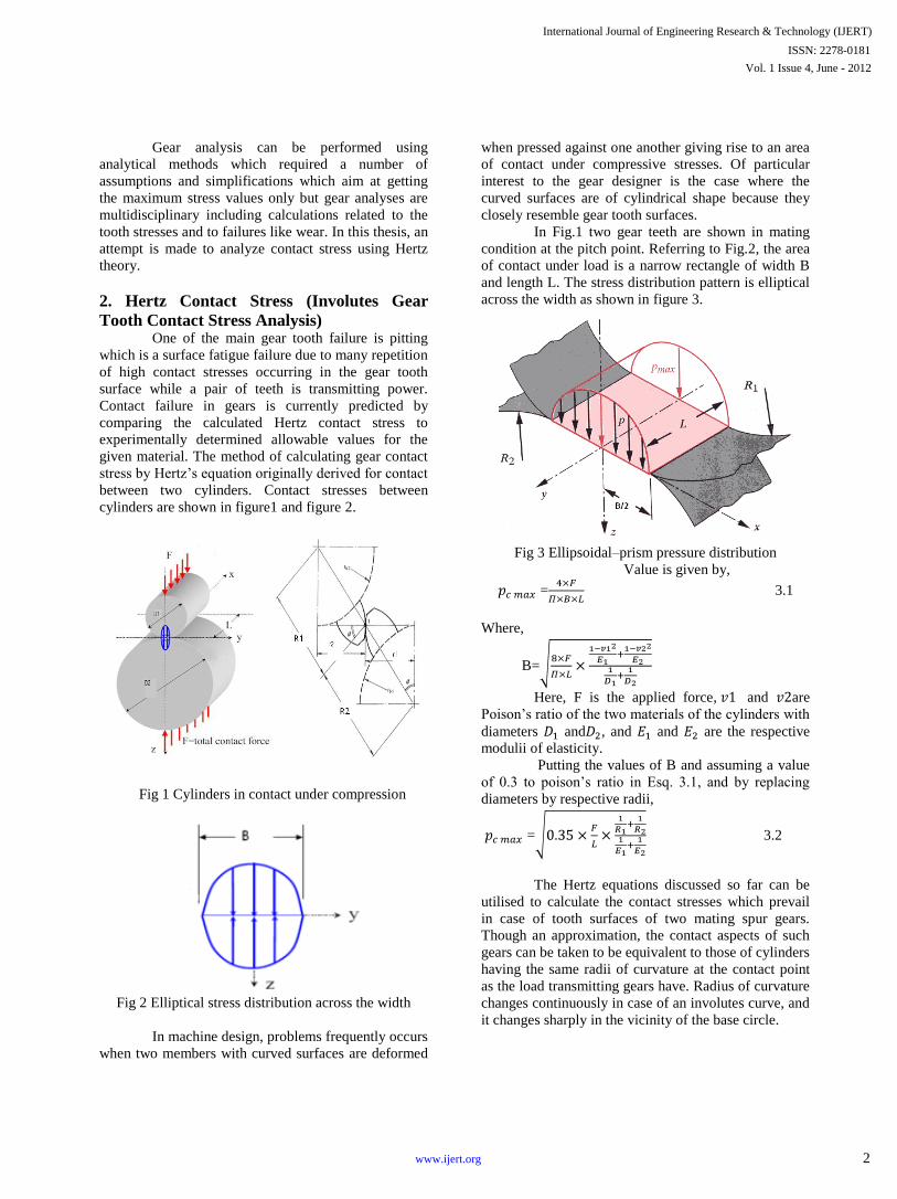
cylinders are shown in figure1 and figure 2.
Fig 1 Cylinders in contact under compression
Fig 2 Elliptical stress distribution across the width
In machine design, problems frequently occurs
when two members with curved surfaces are deformed
when pressed against one another giving rise to an area
of contact under compressive stresses. Of particular
interest to the gear designer is the case where the
curved surfaces are of cylindrical shape because they
closely resemble gear tooth surfaces.
In Fig.1 two gear teeth are shown in mating
condition at the pitch point. Referring to Fig.2, the area
of contact under load is a narrow rectangle of width B
and length L. The stress distribution pattern is elliptical
across the width as shown in figure 3.
Fig 3 Ellipsoidal–prism pressure distribution
Value is given by,
= 3.1
Where,
B=
Here, F is the applied force, and are
Poison’s ratio of the two materials of the cylinders with
diameters and , and and are the respective
modulii of elasticity.
Putting the values of B and assuming a value
of 0.3 to poison’s ratio in Esq. 3.1, and by replacing
diameters by respective radii,
= 3.2
The Hertz equations discussed so far can be
utilised to calculate the contact stresses which prevail
in case of tooth surfaces of two mating spur gears.
Though an approximation, the contact aspects of such
gears can be taken to be equivalent to those of cylinders
having the same radii of curvature at the contact point
as the load transmitting gears have. Radius of curvature
changes continuously in case of an involutes curve, and
it changes sharply in the vicinity of the base circle.
International Journal of Engineering Research & Technology (IJERT)
Vol. 1 Issue 4, June - 2012
ISSN: 2278-0181
2www.ijert.org
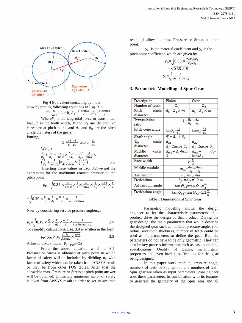
Fig 4 Equivalent contacting cylinder
Now by putting following equations in Esq. 3.1
F= , L = b, = , =
Where is the tangrntial force or transmitted
load, b is the tooth width, and are the radii of
curvature at pitch point, and and are the pitch
circle diameters of the gears.
Putting,
E= and u =
We get
=
= 3.3
Inserting these values in Esq. 3.2 we get the
expression for the maximum contact pressure at the
pitch point
=
=
Now by considering service pressure angle ,
= 3.4
To simplify calculations, Esq. 3.4 is written in the form
= 3.5
Allowable Maximum Pp = /FOS
From the above equation which is 3.5,
Pressure or Stress is obtained at pitch point in which
factor of safety will be included by dividing with
factor of safety which can be taken from ANSYS result
or may be from other FOS tables. After that the
allowable max. Pressure or Stress at pitch point answer
will be obtained. Ultimately minimum factor of safety
is taken from ANSYS result in order to get an accurate
result of allowable max. Pressure or Stress at pitch
point.
Is the material coefficient and is the
pitch point coefficient, which are given by
=
=
=
3. Parametric Modelling of Spur Gear
Table 1 Dimensions of Spur Gear
Parametric modeling allows the design
engineer to let the characteristic parameters of a
product drive the design of that product. During the
gear design, the main parameters that would describe
the designed gear such as module, pressure angle, root
radius, and tooth thickness, number of teeth could be
used as the parameters to define the gear. But, the
parameters do not have to be only geometric. They can
also be key process information such as case hardening
specifications, Quality of grades, metallurgical
properties and even load classifications for the gear
being designed.
In this paper work module, pressure angle,
numbers of teeth of Spur pinion and numbers of teeth
Spur gear are taken as input parameters. Pro/Engineer
uses these parameters, in combination with its features
to generate the geometry of the Spur gear and all
International Journal of Engineering Research & Technology (IJERT)
Vol. 1 Issue 4, June - 2012
ISSN: 2278-0181
3www.ijert.org
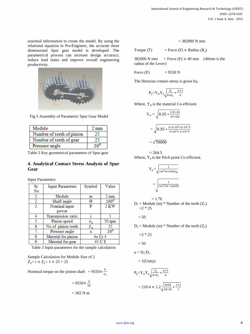
essential information to create the model. By using the
relational equation in Pro/Engineer, the accurate three
dimensional Spur gear model is developed. The
parametrical process can increase design accuracy,
reduce lead times and improve overall engineering
productivity.
Fig 5 Assembly of Parametric Spur Gear Model
Table 2 Key geometrical parameters of Spur gear
4. Analytical Contact Stress Analysis of Spur
Gear
Input Parameters
Table 3 Input parameters for the sample calculation
Sample Calculation for Module Size of 2
= i = 1 25 = 25
Nominal torque on the pinion shaft = 9550
= 9550
= 382 N m
= 382000 N mm
Torque (T) = Force (F) Radius (Ra)
382000 N mm = Force (F) 40 mm {40mm is the
radius of the Lever}
Force (F) = 9550 N
The Hertzian contact stress is given by,
Pp=YmYp
Where, Ym is the material Co-efficient
Ym =
=
=
= 264.5
Where, Yp is the Pitch point Co-efficient.
Yp =
=
= 1.76
D1 = Module (m) * Number of the teeth (Z1)
=2 * 25
= 50
D2 = Module (m) * Number of the teeth (Z2)
=2 * 25
= 50
u = D1/D2
= 1(Unity)
Pp=YmYp
= 210.4 1.2
International Journal of Engineering Research & Technology (IJERT)
Vol. 1 Issue 4, June - 2012
ISSN: 2278-0181
4www.ijert.org
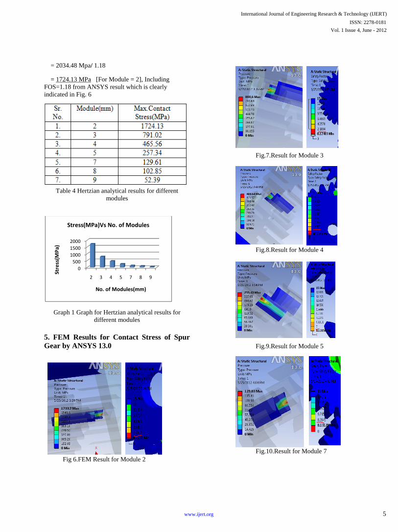
= 2034.48 Mpa/ 1.18
= 1724.13 MPa [For Module = 2], Including
FOS=1.18 from ANSYS result which is clearly
indicated in Fig. 6
Table 4 Hertzian analytical results for different
modules
Graph 1 Graph for Hertzian analytical results for
different modules
5. FEM Results for Contact Stress of Spur
Gear by ANSYS 13.0
Fig 6.FEM Result for Module 2
Fig.7.Result for Module 3
Fig.8.Result for Module 4
Fig.9.Result for Module 5
Fig.10.Result for Module 7
0
500
1000
1500
2000
2 3 4 5 7 8 9
Stre
ss(M
Pa)
No. of Modules(mm)
Stress(MPa)Vs No. of Modules
International Journal of Engineering Research & Technology (IJERT)
Vol. 1 Issue 4, June - 2012
ISSN: 2278-0181
5www.ijert.org
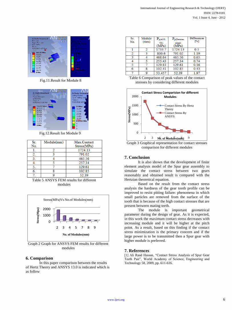
Fig.11.Result for Module 8
Fig.12.Result for Module 9
Table 5 ANSYS FEM results for different
modules
Graph 2 Graph for ANSYS FEM results for different
modules
6. Comparison In this paper comparison between the results
of Hertz Theory and ANSYS 13.0 is indicated which is
as follow
Table 6 Comparison of peak values of the contact
stresses by considering different modules
Graph 3 Graphical representation for contact stresses
comparison for different modules
7. Conclusion It is also shown that the development of finite
element analysis model of the Spur gear assembly to
simulate the contact stress between two gears
reasonably and obtained result is compared with the
Hertzian theoretical equation.
Based on the result from the contact stress
analysis the hardness of the gear tooth profile can be
improved to resist pitting failure: phenomena in which
small particles are removed from the surface of the
tooth that is because of the high contact stresses that are
present between mating teeth.
The module is important geometrical
parameter during the design of gear. As it is expected,
in this work the maximum contact stress decreases with
increasing module and it will be higher at the pitch
point. As a result, based on this finding if the contact
stress minimization is the primary concern and if the
large power is to be transmitted then a Spur gear with
higher module is preferred.
7. References [1] Ali Raad Hassan, “Contact Stress Analysis of Spur Gear
Teeth Pair”, World Academy of Science, Engineering and
Technology 58, 2009, pp. 611-616.
0
1000
2000
2 3 4 5 7 8 9
Str
ess
(Mp
a)
No. of Modules(mm)
Stress(MPa)Vs No.of Modules(mm)
0
500
1000
1500
2000
2 3 4 5 7 8 9
Str
ess
(MP
a)
No. of Modules(mm)
Contact Stress Comparision for different Modules
Contact Stress By Hertz
Theory
Contact Stress By
ANSYS
International Journal of Engineering Research & Technology (IJERT)
Vol. 1 Issue 4, June - 2012
ISSN: 2278-0181
6www.ijert.org

[2] Sorin Cananau, “3D Contact Stress Analysis For Spur
Gears”, University “Politehnica” of Bucharest, Romania, 24-
25 September 2003, pp. 349-351.
[3] Zeping Wei, “Determination and Development of
appropriate models of contact element”, University
“Politehnica” of Bucharest, Romania, October 2009
[4] Zhang Changming, Zhang Hui, “Straight-tooth Bevel
Gear Parametric Design and rapid Prototype manufacturing”,
Shaanxi University of Technology, Hanzhong City, China,
2010, pp. 480-483.
[5] Galina I. Sheveleva, Andrey E. Volkov, Vladimir I.
Medvedev, “Algorithms for analysis of meshing and contact
of spiral bevel gears”, Moscow State University of
Technology, Stankin, Russia,February , 2007, pp. 198-215.
[6] Ivana Atanasovska, Vera Nikolic-Stanojlovic, Dejan
Dimitrijevic, Dejan Momcilovic, “Finite Element Model for
Stress Analysis and Nonlinear Contact Analysis of Helical
Gears ”, Institute Kirilo Savic,Serbia, 5/3/2009, pp. 61-69.
[7] Mike Renfro, “Modelling Gear Teeth in Pro/ENGINEER
Wildfire 4.0” Macmillan”, National Kaohsiung University of
Applied Sciences, Taiwan, 27/5/2010, pp. 398-403.
[8] G. Mallesh, Venkatesh, Shankarmurthy H J, Shiva
Prasad,“ Parametric analysis of Asymmetric Spur Gear
Tooth”, NIT, Durgapur, India, December 17-18, 2009,
pp.398-403.
[9] Shuting Li,“ Finite element analyses for contact strength
and bending strength of a pair of spur gears with machining
errors, assembly errors and tooth modifications”, Heki-cho,
Japan, March 2006, pp. 88-114
[10] Wern-Kueir Jehng, “Computer solid modelling
technologies applied to develop and form mathematical
parametric tooth profiles of bevel gear and skew gear sets”,
National Kaohsiung University of Applied Sciences, Taiwan,
October 2000, pp.160-172.
[11] B.SubbaRao Rao, M.S.Shunmugam, V.Jayaprakash,
“Mathematical Model for Generation of Spiral Bevel Gears ”,
Indian Institute of Technology, Madras, India, 1994, pp. 327-
334.
[12] Faydor L. Litvin, Qi Fan, Robert F. Handschuh,
“Computerized design, simulation of meshing, and contact
and stress analysis of face-milled formate generated spiral
bevel gears ”, University of Illinois at Chicago, Chicago,
USA, December 2001, pp. 441-459.
[13] S. J. Nalluveetti, G. Muiiiuwxappan, “Finite Element
Modelling and Analysis of A Straight Bevel Gear Tooth”
Department of Mechanical Engineering, Indian Institute of
Technology, Madras, India, 1993, pp. 739-744
[14] Gitin M Maitra, Rourkela, Handbook of Gear Design, 2nd
Edn, Tata McGraw-Hill, 1989.
International Journal of Engineering Research & Technology (IJERT)
Vol. 1 Issue 4, June - 2012
ISSN: 2278-0181
7www.ijert.org