Embed Size (px)
Citation preview
CONTENTS
Description Page
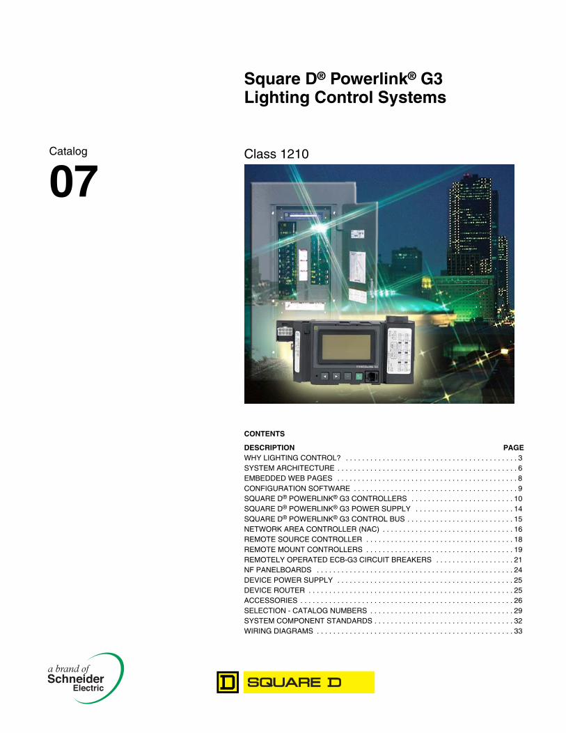
Square D® Powerlink® G3Lighting Control Systems
Class 1210
CONTENTS
DESCRIPTION PAGEWHY LIGHTING CONTROL? . . . . . . . . . . . . . . . . . . . . . . . . . . . . . . . . . . . . . . . . . . 3SYSTEM ARCHITECTURE . . . . . . . . . . . . . . . . . . . . . . . . . . . . . . . . . . . . . . . . . . . . 6EMBEDDED WEB PAGES . . . . . . . . . . . . . . . . . . . . . . . . . . . . . . . . . . . . . . . . . . . . 8CONFIGURATION SOFTWARE . . . . . . . . . . . . . . . . . . . . . . . . . . . . . . . . . . . . . . . . 9SQUARE D® POWERLINK® G3 CONTROLLERS . . . . . . . . . . . . . . . . . . . . . . . . . 10SQUARE D® POWERLINK® G3 POWER SUPPLY . . . . . . . . . . . . . . . . . . . . . . . . 14SQUARE D® POWERLINK® G3 CONTROL BUS . . . . . . . . . . . . . . . . . . . . . . . . . . 15NETWORK AREA CONTROLLER (NAC) . . . . . . . . . . . . . . . . . . . . . . . . . . . . . . . . 16REMOTE SOURCE CONTROLLER . . . . . . . . . . . . . . . . . . . . . . . . . . . . . . . . . . . . 18REMOTE MOUNT CONTROLLERS . . . . . . . . . . . . . . . . . . . . . . . . . . . . . . . . . . . . 19REMOTELY OPERATED ECB-G3 CIRCUIT BREAKERS . . . . . . . . . . . . . . . . . . . 21NF PANELBOARDS . . . . . . . . . . . . . . . . . . . . . . . . . . . . . . . . . . . . . . . . . . . . . . . . 24DEVICE POWER SUPPLY . . . . . . . . . . . . . . . . . . . . . . . . . . . . . . . . . . . . . . . . . . . 25DEVICE ROUTER . . . . . . . . . . . . . . . . . . . . . . . . . . . . . . . . . . . . . . . . . . . . . . . . . . 25ACCESSORIES . . . . . . . . . . . . . . . . . . . . . . . . . . . . . . . . . . . . . . . . . . . . . . . . . . . . 26SELECTION - CATALOG NUMBERS . . . . . . . . . . . . . . . . . . . . . . . . . . . . . . . . . . . 29SYSTEM COMPONENT STANDARDS . . . . . . . . . . . . . . . . . . . . . . . . . . . . . . . . . . 32WIRING DIAGRAMS . . . . . . . . . . . . . . . . . . . . . . . . . . . . . . . . . . . . . . . . . . . . . . . . 33
Catalog
07

Square D® Powerlink® G3 Lighting Control SystemsWhy Lighting Control?
01/07
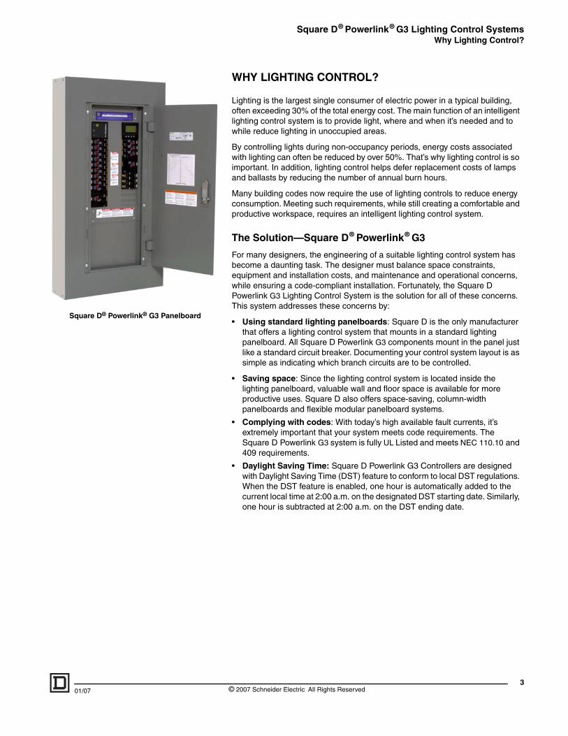
Square D® Powerlink® G3 Panelboard
WHY LIGHTING CONTROL?
Lighting is the largest single consumer of electric power in a typical building, often exceeding 30% of the total energy cost. The main function of an intelligent lighting control system is to provide light, where and when it’s needed and to while reduce lighting in unoccupied areas.
By controlling lights during non-occupancy periods, energy costs associated with lighting can often be reduced by over 50%. That’s why lighting control is so important. In addition, lighting control helps defer replacement costs of lamps and ballasts by reducing the number of annual burn hours.
Many building codes now require the use of lighting controls to reduce energy consumption. Meeting such requirements, while still creating a comfortable and productive workspace, requires an intelligent lighting control system.
The Solution—Square D® Powerlink® G3
For many designers, the engineering of a suitable lighting control system has become a daunting task. The designer must balance space constraints, equipment and installation costs, and maintenance and operational concerns, while ensuring a code-compliant installation. Fortunately, the Square D Powerlink G3 Lighting Control System is the solution for all of these concerns. This system addresses these concerns by:
• Using standard lighting panelboards: Square D is the only manufacturer that offers a lighting control system that mounts in a standard lighting panelboard. All Square D Powerlink G3 components mount in the panel just like a standard circuit breaker. Documenting your control system layout is as simple as indicating which branch circuits are to be controlled.
• Saving space: Since the lighting control system is located inside the lighting panelboard, valuable wall and floor space is available for more productive uses. Square D also offers space-saving, column-width panelboards and flexible modular panelboard systems.
• Complying with codes: With today’s high available fault currents, it’s extremely important that your system meets code requirements. The Square D Powerlink G3 system is fully UL Listed and meets NEC 110.10 and 409 requirements.
• Daylight Saving Time: Square D Powerlink G3 Controllers are designed with Daylight Saving Time (DST) feature to conform to local DST regulations. When the DST feature is enabled, one hour is automatically added to the current local time at 2:00 a.m. on the designated DST starting date. Similarly, one hour is subtracted at 2:00 a.m. on the DST ending date.
3© 2007 Schneider Electric All Rights Reserved
Square D® Powerlink® G3 Lighting Control SystemsWhy Lighting Control?
4
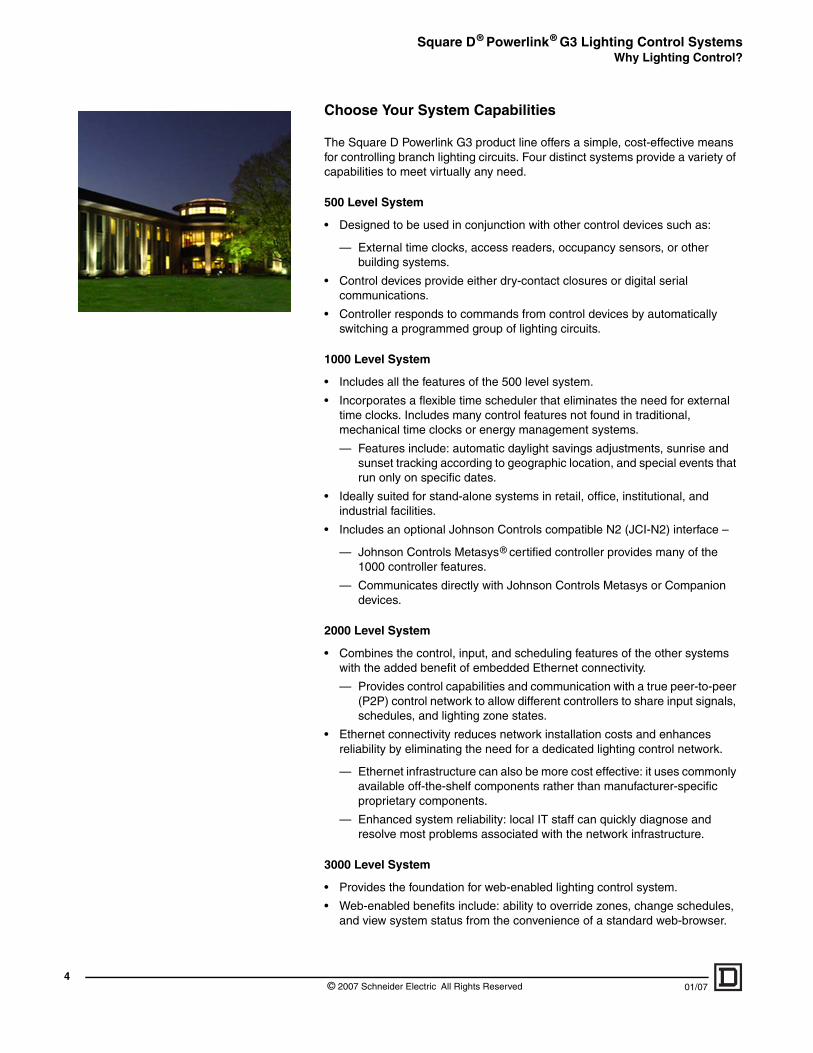
Choose Your System Capabilities
The Square D Powerlink G3 product line offers a simple, cost-effective means for controlling branch lighting circuits. Four distinct systems provide a variety of capabilities to meet virtually any need.
500 Level System
• Designed to be used in conjunction with other control devices such as:
— External time clocks, access readers, occupancy sensors, or other building systems.
• Control devices provide either dry-contact closures or digital serial communications.
• Controller responds to commands from control devices by automatically switching a programmed group of lighting circuits.
1000 Level System
• Includes all the features of the 500 level system.
• Incorporates a flexible time scheduler that eliminates the need for external time clocks. Includes many control features not found in traditional, mechanical time clocks or energy management systems.
— Features include: automatic daylight savings adjustments, sunrise and sunset tracking according to geographic location, and special events that run only on specific dates.
• Ideally suited for stand-alone systems in retail, office, institutional, and industrial facilities.
• Includes an optional Johnson Controls compatible N2 (JCI-N2) interface –
— Johnson Controls Metasys® certified controller provides many of the 1000 controller features.
— Communicates directly with Johnson Controls Metasys or Companion devices.
2000 Level System
• Combines the control, input, and scheduling features of the other systems with the added benefit of embedded Ethernet connectivity.
— Provides control capabilities and communication with a true peer-to-peer (P2P) control network to allow different controllers to share input signals, schedules, and lighting zone states.
• Ethernet connectivity reduces network installation costs and enhances reliability by eliminating the need for a dedicated lighting control network.
— Ethernet infrastructure can also be more cost effective: it uses commonly available off-the-shelf components rather than manufacturer-specific proprietary components.
— Enhanced system reliability: local IT staff can quickly diagnose and resolve most problems associated with the network infrastructure.
3000 Level System
• Provides the foundation for web-enabled lighting control system.
• Web-enabled benefits include: ability to override zones, change schedules, and view system status from the convenience of a standard web-browser.
© 2007 Schneider Electric All Rights Reserved 01/07
Square D® Powerlink® G3 Lighting Control SystemsWhy Lighting Control?
01/07
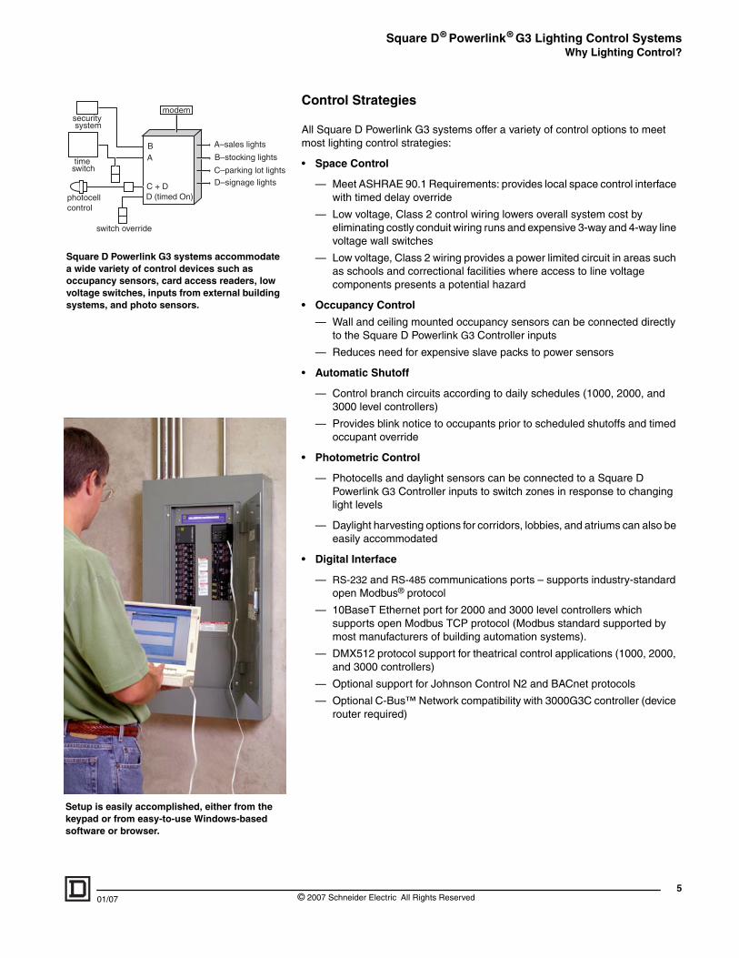
Square D Powerlink G3 systems accommodate a wide variety of control devices such as occupancy sensors, card access readers, low voltage switches, inputs from external building systems, and photo sensors.
Setup is easily accomplished, either from the keypad or from easy-to-use Windows-based software or browser.
Control Strategies
All Square D Powerlink G3 systems offer a variety of control options to meet most lighting control strategies:
• Space Control
— Meet ASHRAE 90.1 Requirements: provides local space control interface with timed delay override
— Low voltage, Class 2 control wiring lowers overall system cost by eliminating costly conduit wiring runs and expensive 3-way and 4-way line voltage wall switches
— Low voltage, Class 2 wiring provides a power limited circuit in areas such as schools and correctional facilities where access to line voltage components presents a potential hazard
• Occupancy Control
— Wall and ceiling mounted occupancy sensors can be connected directly to the Square D Powerlink G3 Controller inputs
— Reduces need for expensive slave packs to power sensors
• Automatic Shutoff
— Control branch circuits according to daily schedules (1000, 2000, and 3000 level controllers)
— Provides blink notice to occupants prior to scheduled shutoffs and timed occupant override
• Photometric Control
— Photocells and daylight sensors can be connected to a Square D Powerlink G3 Controller inputs to switch zones in response to changing light levels
— Daylight harvesting options for corridors, lobbies, and atriums can also be easily accommodated
• Digital Interface
— RS-232 and RS-485 communications ports – supports industry-standard open Modbus® protocol
— 10BaseT Ethernet port for 2000 and 3000 level controllers which supports open Modbus TCP protocol (Modbus standard supported by most manufacturers of building automation systems).
— DMX512 protocol support for theatrical control applications (1000, 2000, and 3000 controllers)
— Optional support for Johnson Control N2 and BACnet protocols
— Optional C-Bus™ Network compatibility with 3000G3C controller (device router required)
5© 2007 Schneider Electric All Rights Reserved
Square D® Powerlink® G3 Lighting Control SystemsSystem Architecture
6
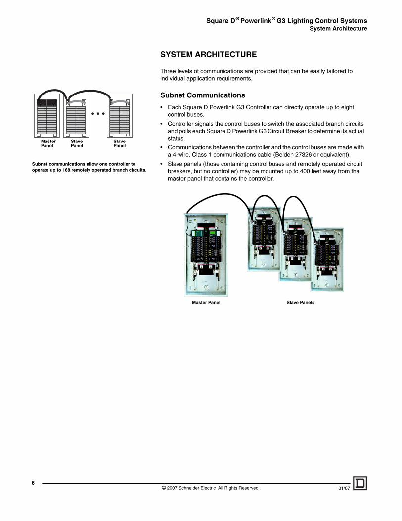
Subnet communications allow one controller to operate up to 168 remotely operated branch circuits.
Slave Panel
Slave Panel
Master Panel
SYSTEM ARCHITECTURE
Three levels of communications are provided that can be easily tailored to individual application requirements.
Subnet Communications
• Each Square D Powerlink G3 Controller can directly operate up to eight control buses.
• Controller signals the control buses to switch the associated branch circuits and polls each Square D Powerlink G3 Circuit Breaker to determine its actual status.
• Communications between the controller and the control buses are made with a 4-wire, Class 1 communications cable (Belden 27326 or equivalent).
• Slave panels (those containing control buses and remotely operated circuit breakers, but no controller) may be mounted up to 400 feet away from the master panel that contains the controller.
Master Panel Slave Panels
© 2007 Schneider Electric All Rights Reserved 01/07
Square D® Powerlink® G3 Lighting Control SystemsSystem Architecture
01/07
Automation networks provide remote access to the lighting control system over an RS-485 network. An RS-485 network consists of low cost, 2-wire, Class 2 communications cable, Belden 9841 or equivalent.
To the PC, Modem, or Building Management System
Slave
Master Slave
Slave
Master Slave
Slave
Master Slave
Automation Network
• Each controller provides both RS-485 and RS-232 serial ports. Provides access up to 247 controllers using an RS-485 multi-drop configuration.
• An automation level network can also be used to communicate with other building systems such as energy management systems and card access controllers. The automation network uses widely accepted and supported industrial-proven protocols used by many building automation manufacturers and systems integrators
— Modbus® ASCII/RTU open protocol in all Square D Powerlink G3 Controllers
— DMX512 protocol in automation level network for theatrical lighting applications in 1000, 2000, and 3000 level controllers
— Optional JCI-N2 protocol for 1000 level controllers
— Optional C-Bus™ Network capability with NF3000G3C controller and device router
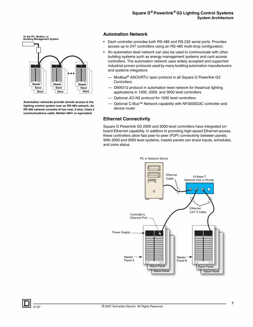
Ethernet Connectivity
Square D Powerlink G3 2000 and 3000 level controllers have integrated on-board Ethernet capability. In addition to providing high-speed Ethernet access, these controllers allow fast peer-to-peer (P2P) connectivity between panels. With 2000 and 3000 level systems, master panels can share inputs, schedules, and zone status.
Power Supply
Master Panel A
Master Panel B
Slave Panel
Slave Panel
Slave Panel
Slave Panel
PC or Network Server
10 Base-TNetwork Hub or Router
Controller’s Ethernet Port
EthernetCAT 5 Cable
Ethernet Cable
7© 2007 Schneider Electric All Rights Reserved
Square D® Powerlink® G3 Lighting Control SystemsEmbedded Web Pages
8
Setup page
Maintenance page
Diagnostics page
Control page
Monitoring page
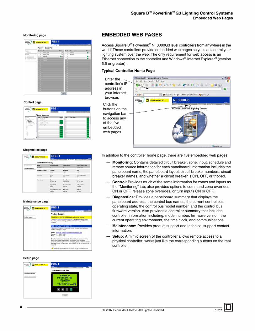
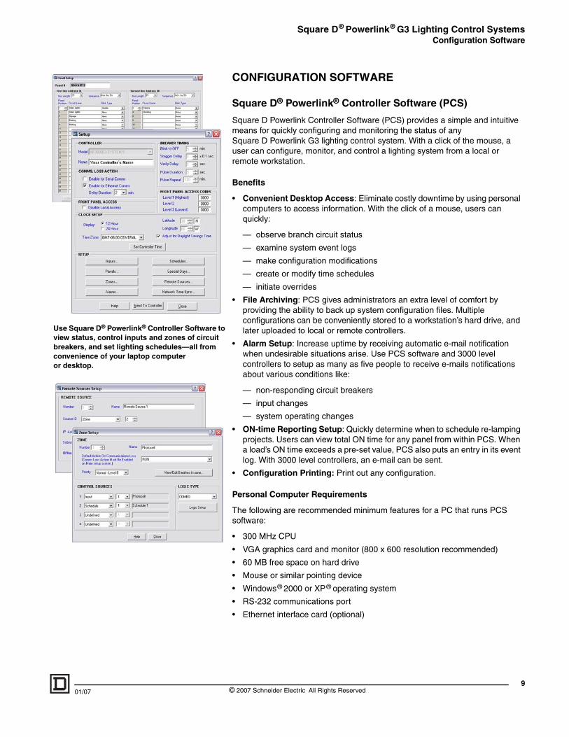
EMBEDDED WEB PAGESAccess Square D® Powerlink® NF3000G3 level controllers from anywhere in the world! These controllers provide embedded web pages so you can control your lighting system over the web. The only requirement for web access is an Ethernet connection to the controller and Windows® Internet Explorer® (version 5.5 or greater).
Typical Controller Home Page
In addition to the controller home page, there are five embedded web pages:
— Monitoring: Contains detailed circuit breaker, zone, input, schedule and remote source information for each panelboard; information includes the panelboard name, the panelboard layout, circuit breaker numbers, circuit breaker names, and whether a circuit breaker is ON, OFF, or tripped.
— Control: Provides much of the same information for zones and inputs as the “Monitoring” tab; also provides options to command zone overrides ON or OFF, release zone overrides, or turn inputs ON or OFF.
— Diagnostics: Provides a panelboard summary that displays the panelboard address, the control bus names, the current control bus operating state, the control bus model number, and the control bus firmware version. Also provides a controller summary that includes controller information including: model number, firmware version, the current operating environment, the time clock, and communications.
— Maintenance: Provides product support and technical support contact information.
— Setup: A mimic screen of the controller allows remote access to a physical controller; works just like the corresponding buttons on the real controller.
Click the buttons on the navigation bar to access any of the five embedded web pages.
Enter the controller’s IP address in your internet browser.
© 2007 Schneider Electric All Rights Reserved 01/07
Square D® Powerlink® G3 Lighting Control SystemsConfiguration Software
01/07
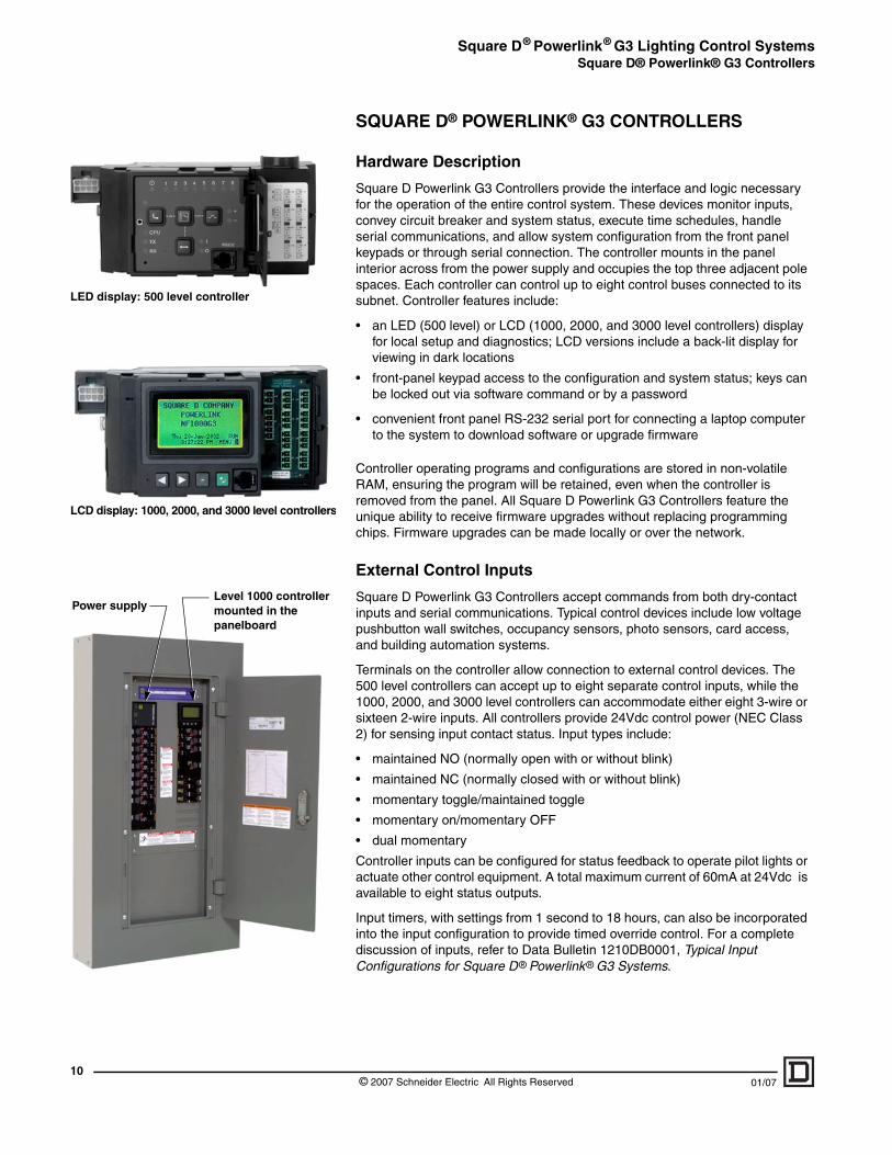
Use Square D® Powerlink® Controller Software toview status, control inputs and zones of circuit breakers, and set lighting schedules—all from convenience of your laptop computer or desktop.
CONFIGURATION SOFTWARE
Square D® Powerlink® Controller Software (PCS)
Square D Powerlink Controller Software (PCS) provides a simple and intuitive means for quickly configuring and monitoring the status of any Square D Powerlink G3 lighting control system. With a click of the mouse, a user can configure, monitor, and control a lighting system from a local or remote workstation.
Benefits
• Convenient Desktop Access: Eliminate costly downtime by using personal computers to access information. With the click of a mouse, users can quickly:
— observe branch circuit status
— examine system event logs
— make configuration modifications
— create or modify time schedules
— initiate overrides
• File Archiving: PCS gives administrators an extra level of comfort by providing the ability to back up system configuration files. Multiple configurations can be conveniently stored to a workstation’s hard drive, and later uploaded to local or remote controllers.
• Alarm Setup: Increase uptime by receiving automatic e-mail notification when undesirable situations arise. Use PCS software and 3000 level controllers to setup as many as five people to receive e-mails notifications about various conditions like:
— non-responding circuit breakers
— input changes
— system operating changes
• ON-time Reporting Setup: Quickly determine when to schedule re-lamping projects. Users can view total ON time for any panel from within PCS. When a load’s ON time exceeds a pre-set value, PCS also puts an entry in its event log. With 3000 level controllers, an e-mail can be sent.
• Configuration Printing: Print out any configuration.
Personal Computer Requirements
The following are recommended minimum features for a PC that runs PCS software:
• 300 MHz CPU
• VGA graphics card and monitor (800 x 600 resolution recommended)
• 60 MB free space on hard drive
• Mouse or similar pointing device
• Windows® 2000 or XP® operating system
• RS-232 communications port
• Ethernet interface card (optional)
9© 2007 Schneider Electric All Rights Reserved
Square D® Powerlink® G3 Lighting Control SystemsSquare D® Powerlink® G3 Controllers
10
LED display: 500 level controller
LCD display: 1000, 2000, and 3000 level controllers
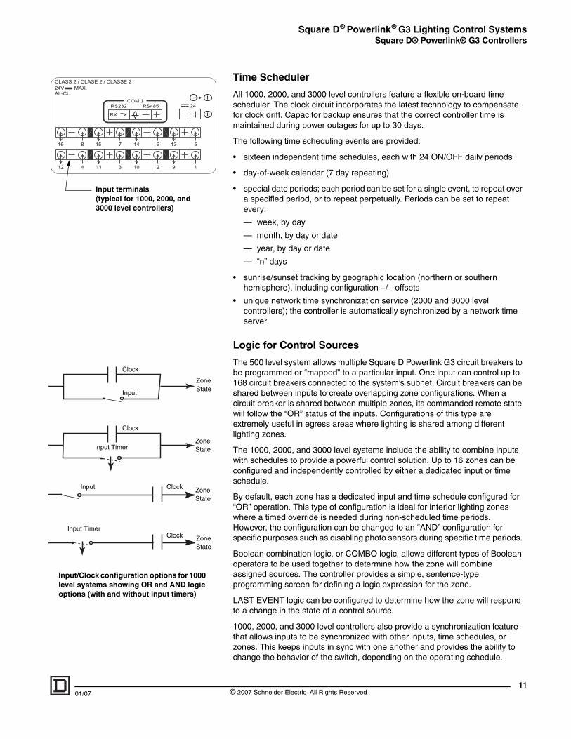
Level 1000 controller mounted in the panelboard
Power supply
SQUARE D® POWERLINK® G3 CONTROLLERS
Hardware Description
Square D Powerlink G3 Controllers provide the interface and logic necessary for the operation of the entire control system. These devices monitor inputs, convey circuit breaker and system status, execute time schedules, handle serial communications, and allow system configuration from the front panel keypads or through serial connection. The controller mounts in the panel interior across from the power supply and occupies the top three adjacent pole spaces. Each controller can control up to eight control buses connected to its subnet. Controller features include:
• an LED (500 level) or LCD (1000, 2000, and 3000 level controllers) display for local setup and diagnostics; LCD versions include a back-lit display for viewing in dark locations
• front-panel keypad access to the configuration and system status; keys can be locked out via software command or by a password
• convenient front panel RS-232 serial port for connecting a laptop computer to the system to download software or upgrade firmware
Controller operating programs and configurations are stored in non-volatile RAM, ensuring the program will be retained, even when the controller is removed from the panel. All Square D Powerlink G3 Controllers feature the unique ability to receive firmware upgrades without replacing programming chips. Firmware upgrades can be made locally or over the network.
External Control Inputs
Square D Powerlink G3 Controllers accept commands from both dry-contact inputs and serial communications. Typical control devices include low voltage pushbutton wall switches, occupancy sensors, photo sensors, card access, and building automation systems.
Terminals on the controller allow connection to external control devices. The 500 level controllers can accept up to eight separate control inputs, while the 1000, 2000, and 3000 level controllers can accommodate either eight 3-wire or sixteen 2-wire inputs. All controllers provide 24Vdc control power (NEC Class 2) for sensing input contact status. Input types include:
• maintained NO (normally open with or without blink)
• maintained NC (normally closed with or without blink)
• momentary toggle/maintained toggle
• momentary on/momentary OFF
• dual momentary
Controller inputs can be configured for status feedback to operate pilot lights or actuate other control equipment. A total maximum current of 60mA at 24Vdc is available to eight status outputs.
Input timers, with settings from 1 second to 18 hours, can also be incorporated into the input configuration to provide timed override control. For a complete discussion of inputs, refer to Data Bulletin 1210DB0001, Typical Input Configurations for Square D® Powerlink® G3 Systems.
© 2007 Schneider Electric All Rights Reserved 01/07
Square D® Powerlink® G3 Lighting Control SystemsSquare D® Powerlink® G3 Controllers
01/07
COM 1
Input terminals (typical for 1000, 2000, and 3000 level controllers)
Input/Clock configuration options for 1000 level systems showing OR and AND logic options (with and without input timers)
Clock
Input
Zone State
Zone State
Zone State
Zone State
Clock
Clock
Clock
Input Timer
Input
Input Timer
Time Scheduler
All 1000, 2000, and 3000 level controllers feature a flexible on-board time scheduler. The clock circuit incorporates the latest technology to compensate for clock drift. Capacitor backup ensures that the correct controller time is maintained during power outages for up to 30 days.
The following time scheduling events are provided:
• sixteen independent time schedules, each with 24 ON/OFF daily periods
• day-of-week calendar (7 day repeating)
• special date periods; each period can be set for a single event, to repeat over a specified period, or to repeat perpetually. Periods can be set to repeat every:
— week, by day
— month, by day or date
— year, by day or date
— “n” days
• sunrise/sunset tracking by geographic location (northern or southern hemisphere), including configuration +/– offsets
• unique network time synchronization service (2000 and 3000 level controllers); the controller is automatically synchronized by a network time server
Logic for Control Sources
The 500 level system allows multiple Square D Powerlink G3 circuit breakers to be programmed or “mapped” to a particular input. One input can control up to 168 circuit breakers connected to the system’s subnet. Circuit breakers can be shared between inputs to create overlapping zone configurations. When a circuit breaker is shared between multiple zones, its commanded remote state will follow the “OR” status of the inputs. Configurations of this type are extremely useful in egress areas where lighting is shared among different lighting zones.
The 1000, 2000, and 3000 level systems include the ability to combine inputs with schedules to provide a powerful control solution. Up to 16 zones can be configured and independently controlled by either a dedicated input or time schedule.
By default, each zone has a dedicated input and time schedule configured for “OR” operation. This type of configuration is ideal for interior lighting zones where a timed override is needed during non-scheduled time periods. However, the configuration can be changed to an “AND” configuration for specific purposes such as disabling photo sensors during specific time periods.
Boolean combination logic, or COMBO logic, allows different types of Boolean operators to be used together to determine how the zone will combine assigned sources. The controller provides a simple, sentence-type programming screen for defining a logic expression for the zone.
LAST EVENT logic can be configured to determine how the zone will respond to a change in the state of a control source.
1000, 2000, and 3000 level controllers also provide a synchronization feature that allows inputs to be synchronized with other inputs, time schedules, or zones. This keeps inputs in sync with one another and provides the ability to change the behavior of the switch, depending on the operating schedule.
11© 2007 Schneider Electric All Rights Reserved
Square D® Powerlink® G3 Lighting Control SystemsSquare D® Powerlink® G3 Controllers
12
CLASS 2 / CLASE 2 / CLASSE 224V MAX.AL-CU
24
5678
1234
COM 1RS232
RX TX
RS485
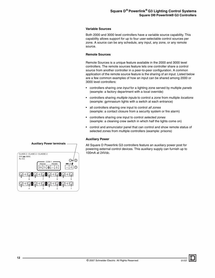
Auxiliary Power terminals
Variable Sources
Both 2000 and 3000 level controllers have a variable source capability. This capability allows support for up to four user-selectable control sources per zone. A source can be any schedule, any input, any zone, or any remote source.
Remote Sources
Remote Sources is a unique feature available in the 2000 and 3000 level controllers. The remote sources feature lets one controller share a control source from another controller in a peer-to-peer configuration. A common application of the remote source feature is the sharing of an input. Listed below are a few common examples of how an input can be shared among 2000 or 3000 level controllers:
• controllers sharing one input for a lighting zone served by multiple panels(example: a factory department with a local override)
• controllers sharing multiple inputs to control a zone from multiple locations (example: gymnasium lights with a switch at each entrance)
• all controllers sharing one input to control all zones (example: a contact closure from a security system or fire alarm)
• controllers sharing one input to control selected zones (example: a cleaning crew switch in which half the lights come on)
• control and annunciator panel that can control and show remote status of selected zones from multiple controllers (example: prisons)
Auxiliary Power
All Square D Powerlink G3 controllers feature an auxiliary power post for powering external control devices. This auxiliary supply can furnish up to 100mA at 24Vdc.
© 2007 Schneider Electric All Rights Reserved 01/07
Square D® Powerlink® G3 Lighting Control SystemsSquare D® Powerlink® G3 Controllers
01/07
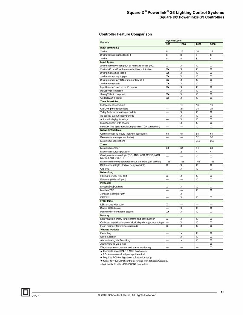
Controller Feature Comparison
FeatureSystem Level
500 1000 2000 3000
Input terminals▲
2-wire 8 16 16 16
2-wire with status feedback ▼ 8 8 8 8
3-wire 8 8 8 8
Input Types
2-wire normally open (NO) or normally closed (NC) X X X X
2-wire NO or NC, with automatic blink notification X◆ X X X
2-wire maintained toggle X◆ X X X
2-wire momentary toggle X◆ X X X
2-wire momentary ON or momentary OFF X◆ X X X
3-wire momentary X◆ X X X
Input timers (1 sec up to 18 hours) X◆ X X X
Input synchronization — X X X
Sentry® Switch support X◆ X X X
On Delay/OFF Delay X◆ X X X
Time Scheduler
Independent schedules — 16 16 16
ON-OFF periods/schedule — 24 24 24
7-day 24-hour repeating schedule — X X X
32 special event/holiday periods — X X X
Automatic daylight savings — X X X
Sunrise/sunset with offsets — X X X
Network time synchronization (requires TCP connection) — — X X
Network Variables
Communications inputs (network accessible) 64 64 64 64
Remote sources (per controller) — — 32 32
Maximum subscriptions — — 256 256
Zones
Maximum number 64 64 64 64
Maximum sources per zone 1 2 4 4
Configurable source logic (OR, AND, XOR, XNOR, NOR, NAND, LAST EVENT)
— — X X
Maximum remotely operated circuit breakers (per subnet) 168 168 168 168
Blink notice (single, double, delay no blink) X X X X
ON-time — X X X
Networking
RS-232 port/RS-485 port X X X X
Ethernet (10BaseT port) — — X X
Protocols
Modbus® ASCII/RTU X X X X
Modbus TCP — — X X
Johnson Controls N2★ — X — —
DMX512 — X X X
Front Panel
LED display with cover X — — —
Backlit LCD display — X X X
Password or front panel disable X◆ X X X
Memory
Non-volatile memory for programs and configuration X X X X
On-board capacitor to power clock chip during power outage — X X X
Flash memory for firmware upgrade X X X X
Viewing Options
Event Log — + X X
Strike Counter — X X X
Alarm viewing via Event Log — + X X
Alarm viewing via e-mail — — — X
Web-based setup, control and status monitoring — — — X
▲ Terminals accept 24–18 AWG conductors.▼ 7.5mA maximum load per input terminal.◆ Requires PCS configuration software for setup.★ Order NF1000G3N2 controller for use with Johnson Controls.+ Not available with NF1000G3N2 controllers.
13© 2007 Schneider Electric All Rights Reserved
Square D® Powerlink® G3 Lighting Control SystemsSquare D® Powerlink® G3 Power Supply
14
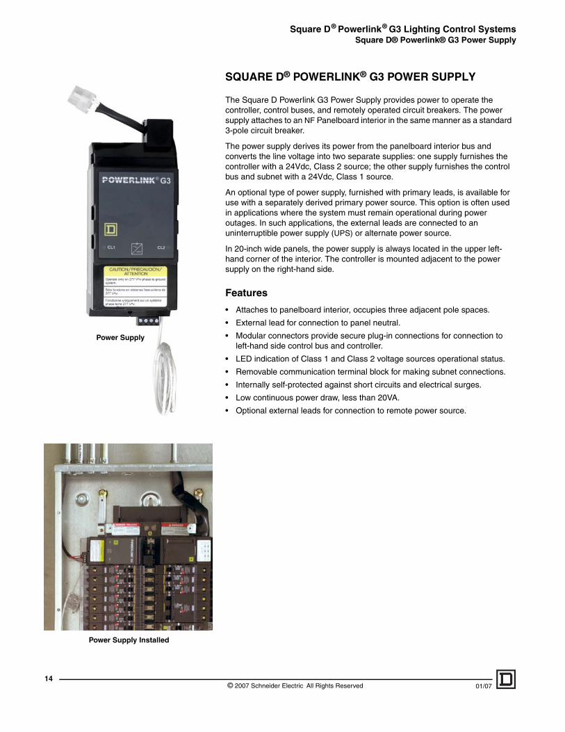
Power Supply Installed
Power Supply
SQUARE D® POWERLINK® G3 POWER SUPPLY
The Square D Powerlink G3 Power Supply provides power to operate the controller, control buses, and remotely operated circuit breakers. The power supply attaches to an NF Panelboard interior in the same manner as a standard 3-pole circuit breaker.
The power supply derives its power from the panelboard interior bus and converts the line voltage into two separate supplies: one supply furnishes the controller with a 24Vdc, Class 2 source; the other supply furnishes the control bus and subnet with a 24Vdc, Class 1 source.
An optional type of power supply, furnished with primary leads, is available for use with a separately derived primary power source. This option is often used in applications where the system must remain operational during power outages. In such applications, the external leads are connected to an uninterruptible power supply (UPS) or alternate power source.
In 20-inch wide panels, the power supply is always located in the upper left-hand corner of the interior. The controller is mounted adjacent to the power supply on the right-hand side.
Features
• Attaches to panelboard interior, occupies three adjacent pole spaces.
• External lead for connection to panel neutral.
• Modular connectors provide secure plug-in connections for connection to left-hand side control bus and controller.
• LED indication of Class 1 and Class 2 voltage sources operational status.
• Removable communication terminal block for making subnet connections.
• Internally self-protected against short circuits and electrical surges.
• Low continuous power draw, less than 20VA.
• Optional external leads for connection to remote power source.
© 2007 Schneider Electric All Rights Reserved 01/07
Square D® Powerlink® G3 Lighting Control SystemsSquare D® Powerlink® G3 Control Bus
01/07
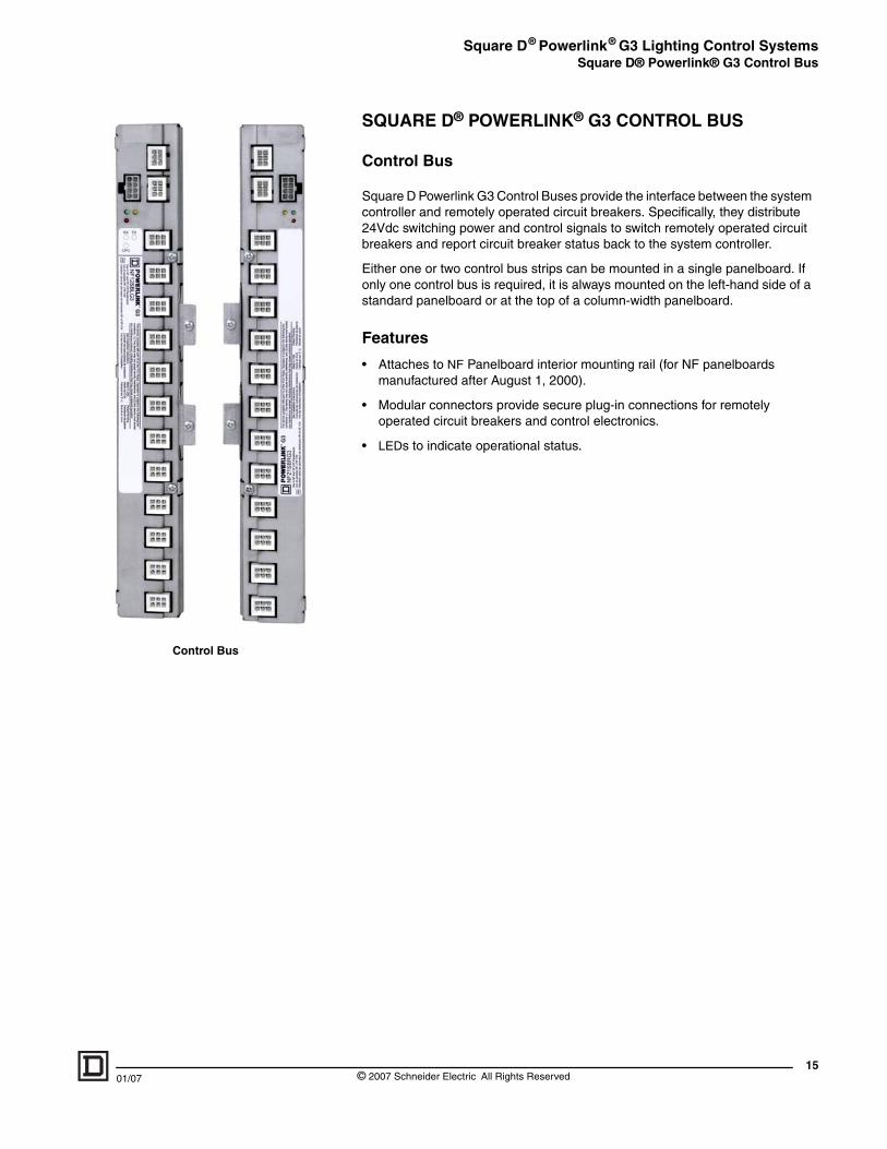
Control Bus
SQUARE D® POWERLINK® G3 CONTROL BUS
Control Bus
Square D Powerlink G3 Control Buses provide the interface between the system controller and remotely operated circuit breakers. Specifically, they distribute 24Vdc switching power and control signals to switch remotely operated circuit breakers and report circuit breaker status back to the system controller.
Either one or two control bus strips can be mounted in a single panelboard. If only one control bus is required, it is always mounted on the left-hand side of a standard panelboard or at the top of a column-width panelboard.
Features
• Attaches to NF Panelboard interior mounting rail (for NF panelboards manufactured after August 1, 2000).
• Modular connectors provide secure plug-in connections for remotely operated circuit breakers and control electronics.
• LEDs to indicate operational status.
15© 2007 Schneider Electric All Rights Reserved
Square D® Powerlink® G3 Lighting Control SystemsNetwork Area Controller (NAC)
16
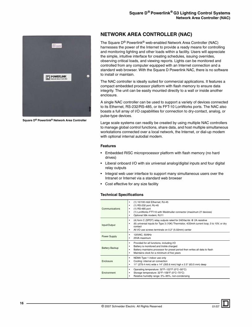
Square D® Powerlink® Network Area Controller
NETWORK AREA CONTROLLER (NAC)
The Square D® Powerlink® web-enabled Network Area Controller (NAC) harnesses the power of the Internet to provide a ready means for controlling and monitoring lighting and other loads within a facility. Users will appreciate the simple, intuitive interface for creating schedules, issuing overrides, observing critical loads, and viewing reports. Lights can be monitored and controlled from any computer equipped with an Internet connection and a standard web browser. With the Square D Powerlink NAC, there is no software to install or maintain.
The NAC controller is ideally suited for commercial applications. It features a compact embedded processor platform with flash memory to ensure data integrity. The unit can be easily mounted directly to a wall or inside another enclosure.
A single NAC controller can be used to support a variety of devices connected to its Ethernet, RS-232/RS-485, or its FFT-10 LonWorks ports. The NAC also boasts a full array of I/O capabilities for connection to dry-contact, analog, or pulse-type devices.
Large scale systems can readily be created by using multiple NAC controllers to manage global control functions, share data, and host multiple simultaneous workstations connected over a local network, the Internet, or dial-up modem with optional internal autodial modem.
Features
• Embedded RISC microprocessor platform with flash memory (no hard drives)
• Liberal onboard I/O with six universal analog/digital inputs and four digital relay outputs
• Integral web user interface to support many simultaneous users over the Intranet or Internet via a standard web browser
• Cost effective for any size facility
Technical Specifications
Communications
• (1) 10/100 mbit Ethernet; RJ-45• (1) RS-232 port; RJ-45• (1) RS-485 port• (1) LonWorks FTT-10 with Weidmuller connector (maximum 27 devices)• Optional 56k modem; RJ11
Input/Output
• (4) form C (SPDT) relay outputs rated for 240Vac/dc @ 2A resistive• (6) universal inputs for Type 3 (10K) Thermistor, 4/20mA current loop, 0 to 10V, or dry
contact• All I/O use screws terminals on 0.2" (5.02mm) center
Power Supply• 120VAC, 50/6Hz• 25VA maximum
Battery Backup
• Provided for all functions, including I/O• Battery is monitored and trickle charged• Battery maintains processor for preset period then writes all data to flash• Maintains clock for a minimum of five years
Enclosure• NEMA Type 1 indoor use only• Cooling: internal air convection• 11" (279.4 mm) wide x 14" (355.6 mm) high x 2.5" (63.5 mm) deep
Environment• Operating temperature: 32°F–122°F (0°C–50°C) • Storage temperature: 32°F–158°F (0°C–70°C)• Relative humidity range: 5%–95%, non-condensing
© 2007 Schneider Electric All Rights Reserved 01/07
Square D® Powerlink® G3 Lighting Control SystemsNetwork Area Controller (NAC)
01/07
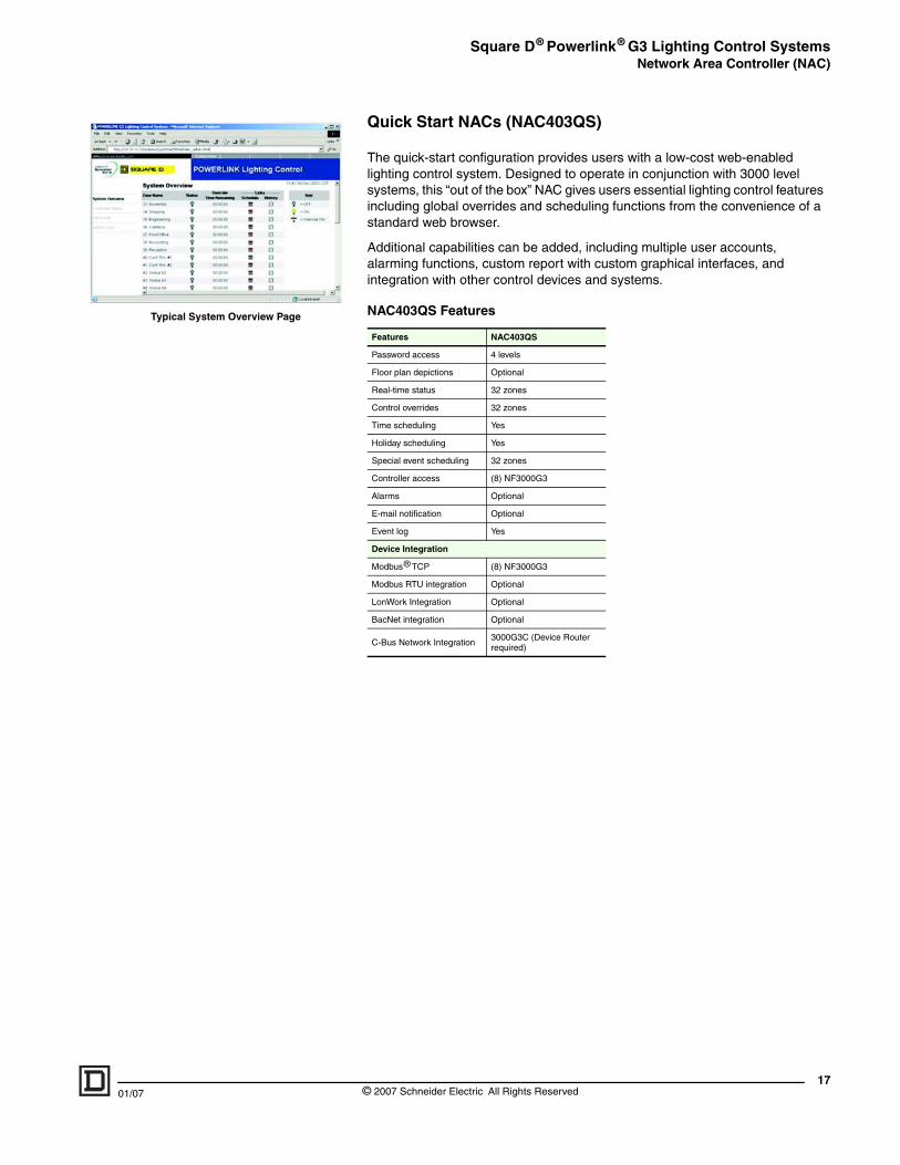
Typical System Overview Page
Quick Start NACs (NAC403QS)
The quick-start configuration provides users with a low-cost web-enabled lighting control system. Designed to operate in conjunction with 3000 level systems, this “out of the box” NAC gives users essential lighting control features including global overrides and scheduling functions from the convenience of a standard web browser.
Additional capabilities can be added, including multiple user accounts, alarming functions, custom report with custom graphical interfaces, and integration with other control devices and systems.
NAC403QS Features
Features NAC403QS
Password access 4 levels
Floor plan depictions Optional
Real-time status 32 zones
Control overrides 32 zones
Time scheduling Yes
Holiday scheduling Yes
Special event scheduling 32 zones
Controller access (8) NF3000G3
Alarms Optional
E-mail notification Optional
Event log Yes
Device Integration
Modbus® TCP (8) NF3000G3
Modbus RTU integration Optional
LonWork Integration Optional
BacNet integration Optional
C-Bus Network Integration3000G3C (Device Router required)
17© 2007 Schneider Electric All Rights Reserved
Square D® Powerlink® G3 Lighting Control SystemsRemote Source Controller
18
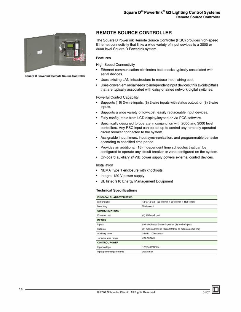
Square D Powerlink Remote Source Controller
REMOTE SOURCE CONTROLLER
The Square D Powerlink Remote Source Controller (RSC) provides high-speed Ethernet connectivity that links a wide variety of input devices to a 2000 or 3000 level Square D Powerlink system.
Features
High Speed Connectivity
• Ethernet communication eliminates bottlenecks typically associated with serial devices.
• Uses existing LAN infrastructure to reduce input wiring cost.
• Uses convenient radial feeds to independent input devices; this avoids pitfalls that are typically associated with daisy-chained network digital switches.
Powerful Control Capability• Supports (16) 2-wire inputs, (8) 2-wire inputs with status output, or (8) 3-wire
inputs.
• Supports a wide variety of low-cost, easily replaceable input devices.
• Fully configurable from LCD display/keypad or via PCS software.
• Specifically designed to operate in conjunction with 2000 and 3000 level controllers. Any RSC input can be set up to control any remotely operated circuit breaker connected to the system.
• Assignable input timers, input synchronization, and programmable behavior according to specified time period.
• Provides an additional (16) independent time schedules that can be configured to operate any circuit breaker or zone configured on the system.
• On-board auxiliary 24Vdc power supply powers external control devices.
Installation• NEMA Type 1 enclosure with knockouts
• Integral 120 V power supply
• UL listed 916 Energy Management Equipment
Technical Specifications
PHYSICAL CHARACTERISTICS
Dimensions 12" x 12" x 6" (304.8 mm x 304.8 mm x 152.4 mm)
Mounting Wall mount
COMMUNICATIONS
Ethernet port (1) 10BaseT port
INPUTS
Inputs (16) dedicated 2-wire inputs or (8) 3-wire inputs
Outputs (8) outputs (max of 60ma total for all outputs combined)
Auxiliary power 24Vdc (100ma max)
Terminal wire range #24-18AWG
CONTROL POWER
Input voltage 120/240/277Vac
Input power requirements 20VA max
© 2007 Schneider Electric All Rights Reserved 01/07
Square D® Powerlink® G3 Lighting Control SystemsRemote Mount Controllers
01/07
Maximum Sub-net Wiring Distance
Nominal Voltage Power Supply Max Cable Length
120 V 400 ft (122 m)
240 V 400 ft (122 m)
277 V 400 ft (122 m)
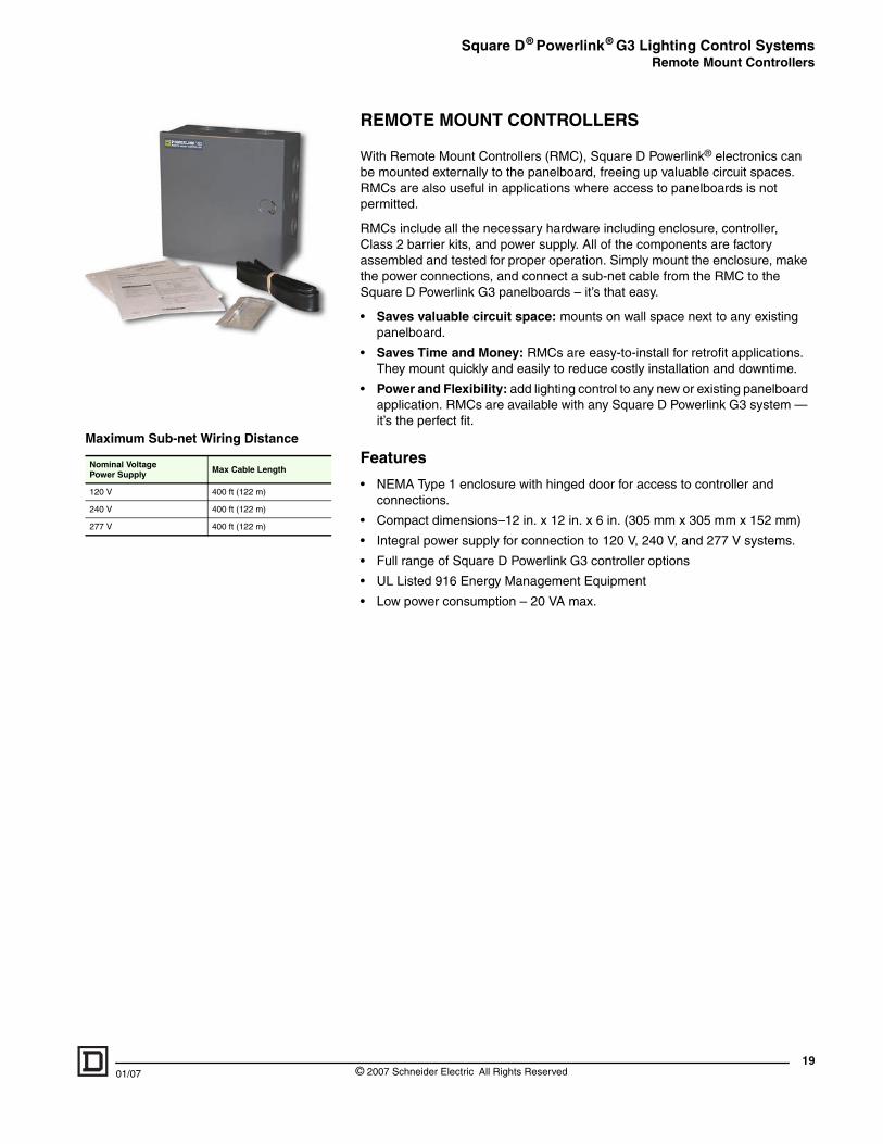
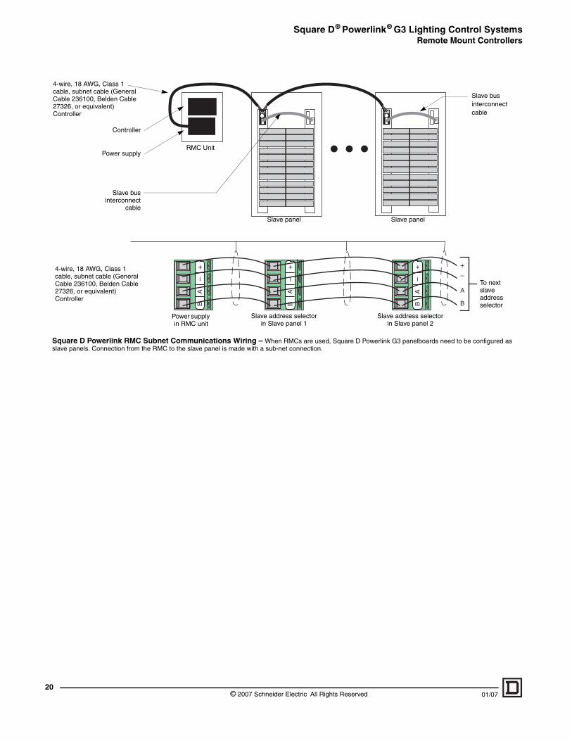
REMOTE MOUNT CONTROLLERS
With Remote Mount Controllers (RMC), Square D Powerlink® electronics can be mounted externally to the panelboard, freeing up valuable circuit spaces. RMCs are also useful in applications where access to panelboards is not permitted.
RMCs include all the necessary hardware including enclosure, controller, Class 2 barrier kits, and power supply. All of the components are factory assembled and tested for proper operation. Simply mount the enclosure, make the power connections, and connect a sub-net cable from the RMC to the Square D Powerlink G3 panelboards – it’s that easy.
• Saves valuable circuit space: mounts on wall space next to any existing panelboard.
• Saves Time and Money: RMCs are easy-to-install for retrofit applications. They mount quickly and easily to reduce costly installation and downtime.
• Power and Flexibility: add lighting control to any new or existing panelboard application. RMCs are available with any Square D Powerlink G3 system — it’s the perfect fit.
Features
• NEMA Type 1 enclosure with hinged door for access to controller and connections.
• Compact dimensions–12 in. x 12 in. x 6 in. (305 mm x 305 mm x 152 mm)
• Integral power supply for connection to 120 V, 240 V, and 277 V systems.
• Full range of Square D Powerlink G3 controller options
• UL Listed 916 Energy Management Equipment
• Low power consumption – 20 VA max.
19© 2007 Schneider Electric All Rights Reserved
Square D® Powerlink® G3 Lighting Control SystemsRemote Mount Controllers
20
AB
–+
Power supply
Controller
RMC Unit
4-wire, 18 AWG, Class 1 cable, subnet cable (General Cable 236100, Belden Cable 27326, or equivalent) Controller
Slave businterconnect
cable
Power supply in RMC unit
4-wire, 18 AWG, Class 1 cable, subnet cable (General Cable 236100, Belden Cable 27326, or equivalent) Controller
Square D Powerlink RMC Subnet Communicatioslave panels. Connection from the RMC to the slave panel
A
B
–+
AB
–+
AB
–+
Slave panelSlave panel
Slave bus interconnect cable
Slave address selector in Slave panel 2
Slave address selector in Slave panel 1
To next slave address selector
ns Wiring – When RMCs are used, Square D Powerlink G3 panelboards need to be configured as is made with a sub-net connection.
© 2007 Schneider Electric All Rights Reserved 01/07
Square D® Powerlink® G3 Lighting Control SystemsRemotely Operated ECB-G3 Circuit Breakers
01/07
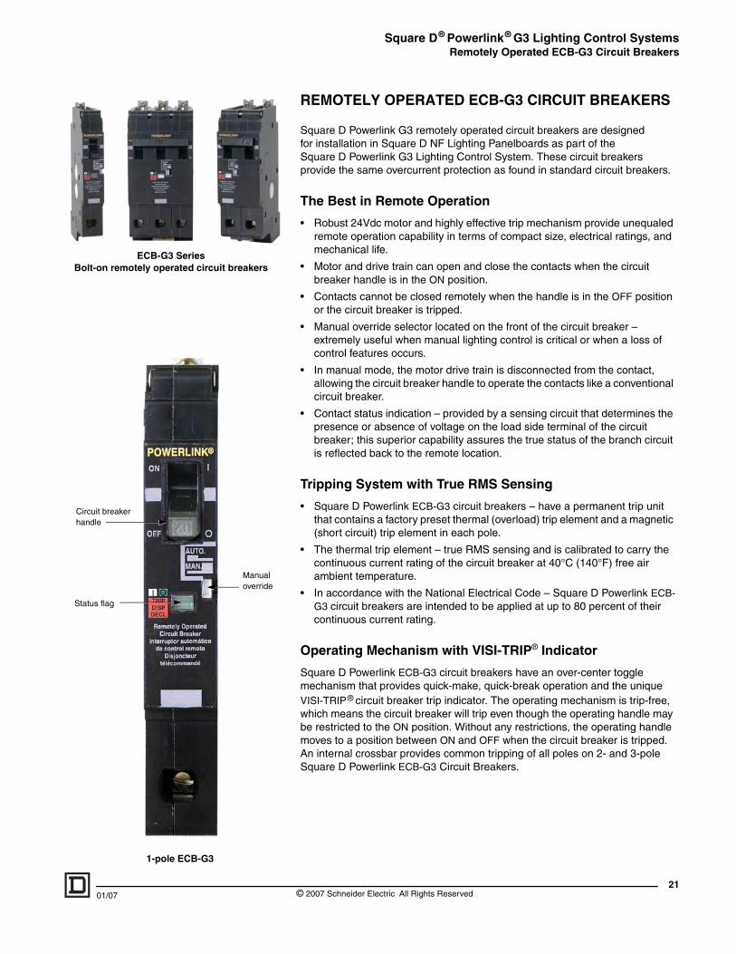
ECB-G3 SeriesBolt-on remotely operated circuit breakers
1-pole ECB-G3
Manual override
Status flag
Circuit breaker handle
REMOTELY OPERATED ECB-G3 CIRCUIT BREAKERS
Square D Powerlink G3 remotely operated circuit breakers are designed for installation in Square D NF Lighting Panelboards as part of the Square D Powerlink G3 Lighting Control System. These circuit breakers provide the same overcurrent protection as found in standard circuit breakers.
The Best in Remote Operation
• Robust 24Vdc motor and highly effective trip mechanism provide unequaled remote operation capability in terms of compact size, electrical ratings, and mechanical life.
• Motor and drive train can open and close the contacts when the circuit breaker handle is in the ON position.
• Contacts cannot be closed remotely when the handle is in the OFF position or the circuit breaker is tripped.
• Manual override selector located on the front of the circuit breaker – extremely useful when manual lighting control is critical or when a loss of control features occurs.
• In manual mode, the motor drive train is disconnected from the contact, allowing the circuit breaker handle to operate the contacts like a conventional circuit breaker.
• Contact status indication – provided by a sensing circuit that determines the presence or absence of voltage on the load side terminal of the circuit breaker; this superior capability assures the true status of the branch circuit is reflected back to the remote location.
Tripping System with True RMS Sensing
• Square D Powerlink ECB-G3 circuit breakers – have a permanent trip unit that contains a factory preset thermal (overload) trip element and a magnetic (short circuit) trip element in each pole.
• The thermal trip element – true RMS sensing and is calibrated to carry the continuous current rating of the circuit breaker at 40°C (140°F) free air ambient temperature.
• In accordance with the National Electrical Code – Square D Powerlink ECB-G3 circuit breakers are intended to be applied at up to 80 percent of their continuous current rating.
Operating Mechanism with VISI-TRIP® Indicator
Square D Powerlink ECB-G3 circuit breakers have an over-center toggle mechanism that provides quick-make, quick-break operation and the unique VISI-TRIP® circuit breaker trip indicator. The operating mechanism is trip-free, which means the circuit breaker will trip even though the operating handle may be restricted to the ON position. Without any restrictions, the operating handle moves to a position between ON and OFF when the circuit breaker is tripped. An internal crossbar provides common tripping of all poles on 2- and 3-pole Square D Powerlink ECB-G3 Circuit Breakers.
21© 2007 Schneider Electric All Rights Reserved
Square D® Powerlink® G3 Lighting Control SystemsRemotely Operated ECB-G3 Circuit Breakers
22
Features
• Overcurrent protection—UL Listed 489
• Series connected ratings up to 200,000 RMS symmetrical amperes
• Integral ON/OFF/trip status position indicator, visible without removing trim.
• Manual override
• Rated for a full 200,000 remote On/Off/On sequence of operations
• Bolt-on line connectors
• Oversized load lugs
• Modular control connectors
• UL Listed for high intensity discharge lighting (HID)
• UL Listed switch duty rated (SWD), and heating, air-conditioning, refrigeration rated (HACR)
• Special emergency lighting option for meeting NEC 700.12e
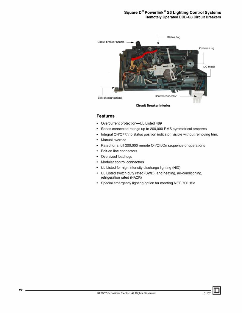
Oversize lug
DC motor
Bolt-on connectionsControl connector
Circuit Breaker Interior
Circuit breaker handle
Status flag
© 2007 Schneider Electric All Rights Reserved 01/07
Square D® Powerlink® G3 Lighting Control SystemsRemotely Operated ECB-G3 Circuit Breakers
01/07
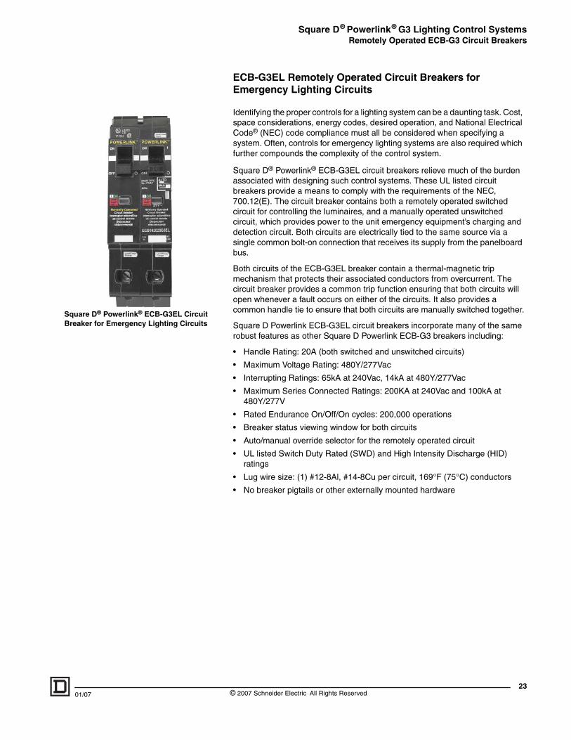
Square D® Powerlink® ECB-G3EL Circuit Breaker for Emergency Lighting Circuits
ECB-G3EL Remotely Operated Circuit Breakers for Emergency Lighting Circuits
Identifying the proper controls for a lighting system can be a daunting task. Cost, space considerations, energy codes, desired operation, and National Electrical Code® (NEC) code compliance must all be considered when specifying a system. Often, controls for emergency lighting systems are also required which further compounds the complexity of the control system.
Square D® Powerlink® ECB-G3EL circuit breakers relieve much of the burden associated with designing such control systems. These UL listed circuit breakers provide a means to comply with the requirements of the NEC, 700.12(E). The circuit breaker contains both a remotely operated switched circuit for controlling the luminaires, and a manually operated unswitched circuit, which provides power to the unit emergency equipment’s charging and detection circuit. Both circuits are electrically tied to the same source via a single common bolt-on connection that receives its supply from the panelboard bus.
Both circuits of the ECB-G3EL breaker contain a thermal-magnetic trip mechanism that protects their associated conductors from overcurrent. The circuit breaker provides a common trip function ensuring that both circuits will open whenever a fault occurs on either of the circuits. It also provides a common handle tie to ensure that both circuits are manually switched together.
Square D Powerlink ECB-G3EL circuit breakers incorporate many of the same robust features as other Square D Powerlink ECB-G3 breakers including:
• Handle Rating: 20A (both switched and unswitched circuits)
• Maximum Voltage Rating: 480Y/277Vac
• Interrupting Ratings: 65kA at 240Vac, 14kA at 480Y/277Vac
• Maximum Series Connected Ratings: 200KA at 240Vac and 100kA at 480Y/277V
• Rated Endurance On/Off/On cycles: 200,000 operations
• Breaker status viewing window for both circuits
• Auto/manual override selector for the remotely operated circuit
• UL listed Switch Duty Rated (SWD) and High Intensity Discharge (HID) ratings
• Lug wire size: (1) #12-8Al, #14-8Cu per circuit, 169°F (75°C) conductors
• No breaker pigtails or other externally mounted hardware
23© 2007 Schneider Electric All Rights Reserved
Square D® Powerlink® G3 Lighting Control SystemsNF Panelboards
24
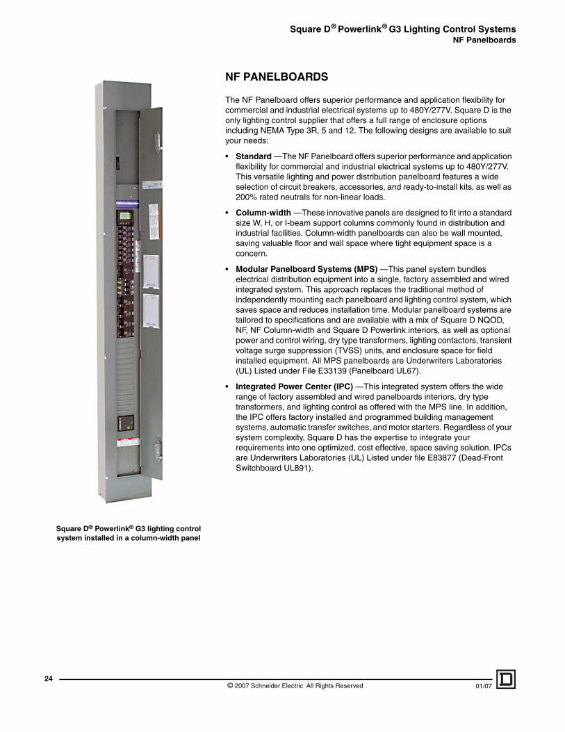
Square D® Powerlink® G3 lighting control system installed in a column-width panel
NF PANELBOARDS
The NF Panelboard offers superior performance and application flexibility for commercial and industrial electrical systems up to 480Y/277V. Square D is the only lighting control supplier that offers a full range of enclosure options including NEMA Type 3R, 5 and 12. The following designs are available to suit your needs:
• Standard —The NF Panelboard offers superior performance and application flexibility for commercial and industrial electrical systems up to 480Y/277V. This versatile lighting and power distribution panelboard features a wide selection of circuit breakers, accessories, and ready-to-install kits, as well as 200% rated neutrals for non-linear loads.
• Column-width —These innovative panels are designed to fit into a standard size W, H, or I-beam support columns commonly found in distribution and industrial facilities. Column-width panelboards can also be wall mounted, saving valuable floor and wall space where tight equipment space is a concern.
• Modular Panelboard Systems (MPS) —This panel system bundles electrical distribution equipment into a single, factory assembled and wired integrated system. This approach replaces the traditional method of independently mounting each panelboard and lighting control system, which saves space and reduces installation time. Modular panelboard systems are tailored to specifications and are available with a mix of Square D NQOD, NF, NF Column-width and Square D Powerlink interiors, as well as optional power and control wiring, dry type transformers, lighting contactors, transient voltage surge suppression (TVSS) units, and enclosure space for field installed equipment. All MPS panelboards are Underwriters Laboratories (UL) Listed under File E33139 (Panelboard UL67).
• Integrated Power Center (IPC) —This integrated system offers the wide range of factory assembled and wired panelboards interiors, dry type transformers, and lighting control as offered with the MPS line. In addition, the IPC offers factory installed and programmed building management systems, automatic transfer switches, and motor starters. Regardless of your system complexity, Square D has the expertise to integrate your requirements into one optimized, cost effective, space saving solution. IPCs are Underwriters Laboratories (UL) Listed under file E83877 (Dead-Front Switchboard UL891).
© 2007 Schneider Electric All Rights Reserved 01/07
Square D® Powerlink® G3 Lighting Control SystemsDevice Power Supply
01/07
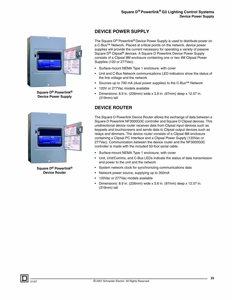
Square D® Powerlink® Device Power Supply
Square D® Powerlink® Device Router
DEVICE POWER SUPPLY
The Square D® Powerlink® Device Power Supply is used to distribute power on a C-Bus™ Network. Placed at critical points on the network, device power supplies will provide the current necessary for operating a variety of passive Square D® Clipsal® devices. A Square D Powerlink Device Power Supply consists of a Clipsal 8M enclosure containing one or two 4M Clipsal Power Supplies (120 or 277Vac).
• Surface-mount NEMA Type 1 enclosure, with cover
• Unit and C-Bus Network communications LED indicators show the status of the line voltage and the network
• Sources up to 700 mA (dual power supplies) to the C-Bus™ Network
• 120V or 277Vac models available
• Dimensions: 8.9 in. (226mm) wide x 3.8 in. (97mm) deep x 12.57 in. (319mm) tall
DEVICE ROUTER
The Square D Powerlink Device Router allows the exchange of data between a Square D Powerlink NF3000G3C controller and Square D Clipsal devices. This unidirectional device router receives data from Clipsal input devices such as keypads and touchscreens and sends data to Clipsal output devices such as relays and dimmers. The device router consists of a Clipsal 8M enclosure containing a Clipsal PC Interface and a Clipsal Power Supply (120Vac or 277Vac). Communication between the device router and the NF3000G3C controller is made with the included 50-foot serial cable.
• Surface-mount NEMA Type 1 enclosure, with cover
• Unit, Unit/Comms, and C-Bus LEDs indicate the status of data transmission and power to the unit and the network
• System network clock for synchronizing communications data
• Network power source, supplying up to 350mA
• 120Vac or 277Vac models available
• Dimensions: 8.9 in. (226mm) wide x 3.8 in. (97mm) deep x 12.57 in. (319mm) tall
25© 2007 Schneider Electric All Rights Reserved
Square D® Powerlink® G3 Lighting Control SystemsAccessories
26
Slave Address Selector
Slave Bus Connect Harness
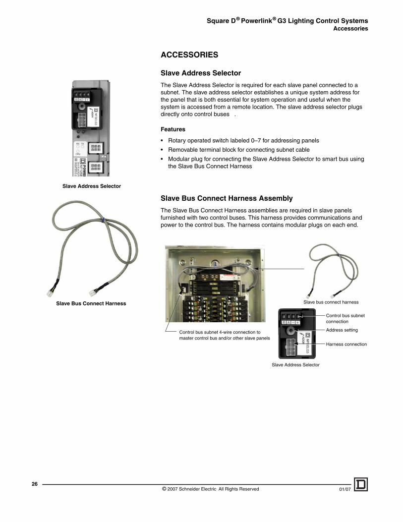
ACCESSORIES
Slave Address Selector
The Slave Address Selector is required for each slave panel connected to a subnet. The slave address selector establishes a unique system address for the panel that is both essential for system operation and useful when the system is accessed from a remote location. The slave address selector plugs directly onto control buses .
Features
• Rotary operated switch labeled 0–7 for addressing panels
• Removable terminal block for connecting subnet cable
• Modular plug for connecting the Slave Address Selector to smart bus using the Slave Bus Connect Harness
Slave Bus Connect Harness Assembly
The Slave Bus Connect Harness assemblies are required in slave panels furnished with two control buses. This harness provides communications and power to the control bus. The harness contains modular plugs on each end.
Slave bus connect harness
Control bus subnet 4-wire connection to master control bus and/or other slave panels
Control bus subnet connection
Address setting
Harness connection
Slave Address Selector
© 2007 Schneider Electric All Rights Reserved 01/07

Square D® Powerlink® G3 Lighting Control SystemsAccessories
01/07
Column-width Controller Cable
Remote Mounting Adapter
Serial Cable
Column-width Controller Cable
A Column-width Controller Cable is required to connect the power supply to the controller when used in an NF Column-width Panelboard.
Remote Mounting Adapter
The Remote Mounting Adapter provides a means for mounting the Square D Powerlink G3 panels with a controller and power supply in a separate enclosure. This bracket is ideal for retrofit applications where all 42 circuit spaces in the panelboard are required for branch circuit breakers.
If ordering the Remote Mounting Adapter, order power supplies with the (L) suffix. Communications to the Square D Powerlink G3 panels are made with a subnet connection.
NOTE: Every panel will require its own Slave Address Selector NFSELG3.
Controller Front Panel Serial Cable
The Controller Front Panel Serial Cable is used to make direct RS-232 connections from the controller to a PC or laptop computer.
27© 2007 Schneider Electric All Rights Reserved
Square D® Powerlink® G3 Lighting Control SystemsAccessories
28
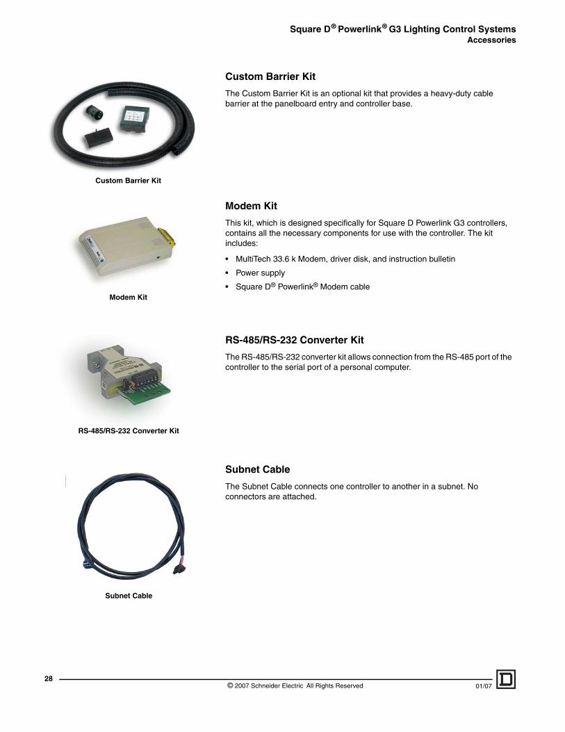
Custom Barrier Kit
Modem Kit
RS-485/RS-232 Converter Kit
Subnet Cable
Custom Barrier Kit
The Custom Barrier Kit is an optional kit that provides a heavy-duty cable barrier at the panelboard entry and controller base.
Modem Kit
This kit, which is designed specifically for Square D Powerlink G3 controllers, contains all the necessary components for use with the controller. The kit includes:
• MultiTech 33.6 k Modem, driver disk, and instruction bulletin
• Power supply
• Square D® Powerlink® Modem cable
RS-485/RS-232 Converter Kit
The RS-485/RS-232 converter kit allows connection from the RS-485 port of the controller to the serial port of a personal computer.
Subnet Cable
The Subnet Cable connects one controller to another in a subnet. No connectors are attached.
© 2007 Schneider Electric All Rights Reserved 01/07
Square D® Powerlink® G3 Lighting Control SystemsSelection - Catalog Numbers
01/07
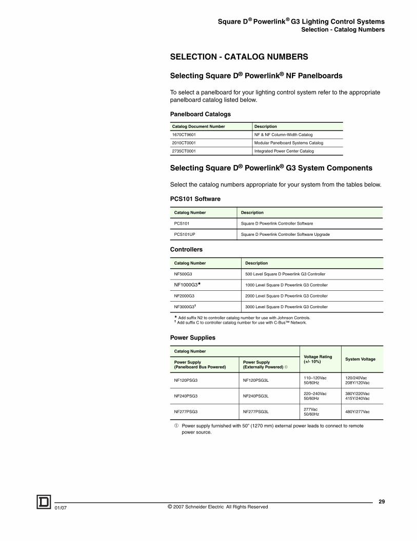
SELECTION - CATALOG NUMBERS
Selecting Square D® Powerlink® NF Panelboards
To select a panelboard for your lighting control system refer to the appropriate panelboard catalog listed below.
Selecting Square D® Powerlink® G3 System Components
Select the catalog numbers appropriate for your system from the tables below.
Panelboard Catalogs
Catalog Document Number Description
1670CT9601 NF & NF Column-Width Catalog
2010CT0001 Modular Panelboard Systems Catalog
2735CT0001 Integrated Power Center Catalog
PCS101 Software
Catalog Number Description
PCS101 Square D Powerlink Controller Software
PCS101UP Square D Powerlink Controller Software Upgrade
Controllers
Catalog Number Description
NF500G3 500 Level Square D Powerlink G3 Controller
NF1000G3★ 1000 Level Square D Powerlink G3 Controller
NF2000G3 2000 Level Square D Powerlink G3 Controller
NF3000G3✝ 3000 Level Square D Powerlink G3 Controller
★ Add suffix N2 to controller catalog number for use with Johnson Controls.✝ Add suffix C to controller catalog number for use with C-Bus™ Network.
Power Supplies
Catalog NumberVoltage Rating(+/- 10%) System Voltage
Power Supply(Panelboard Bus Powered)
Power Supply (Externally Powered) ➀
NF120PSG3 NF120PSG3L110–120Vac50/60Hz
120/240Vac208Y/120Vac
NF240PSG3 NF240PSG3L220–240Vac50/60Hz
380Y/220Vac415Y/240Vac
NF277PSG3 NF277PSG3L277Vac50/60Hz
480Y/277Vac
➀ Power supply furnished with 50” (1270 mm) external power leads to connect to remote power source.
29© 2007 Schneider Electric All Rights Reserved
Square D® Powerlink® G3 Lighting Control SystemsSelection - Catalog Numbers
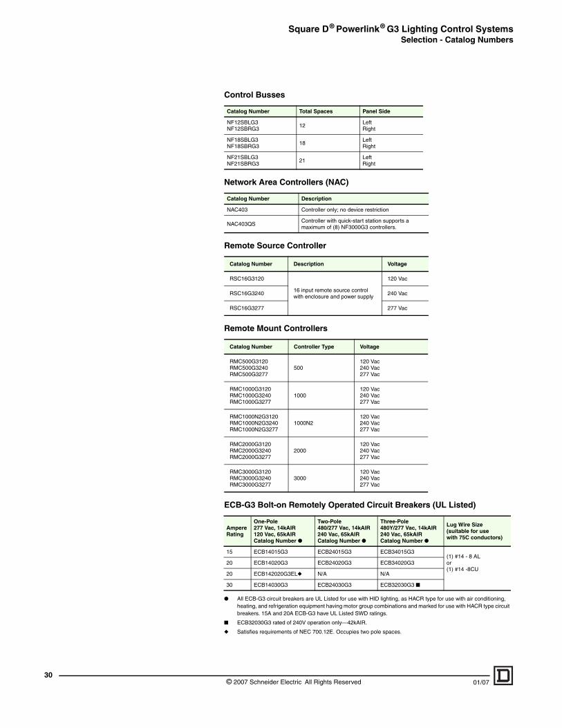
30
● All ECB-G3 circuit breakers are UL Listed for use with HID lighting, as HACR type for use with air conditioning, heating, and refrigeration equipment having motor group combinations and marked for use with HACR type circuit breakers. 15A and 20A ECB-G3 have UL Listed SWD ratings.
■ ECB32030G3 rated of 240V operation only—42kAIR.
◆ Satisfies requirements of NEC 700.12E. Occupies two pole spaces.
Control Busses
Catalog Number Total Spaces Panel Side
NF12SBLG3NF12SBRG3
12LeftRight
NF18SBLG3NF18SBRG3
18LeftRight
NF21SBLG3NF21SBRG3
21LeftRight
Network Area Controllers (NAC)
Catalog Number Description
NAC403 Controller only; no device restriction
NAC403QSController with quick-start station supports a maximum of (8) NF3000G3 controllers.
Remote Source Controller
Catalog Number Description Voltage
RSC16G3120
16 input remote source control with enclosure and power supply
120 Vac
RSC16G3240 240 Vac
RSC16G3277 277 Vac
Remote Mount Controllers
Catalog Number Controller Type Voltage
RMC500G3120RMC500G3240RMC500G3277
500120 Vac240 Vac277 Vac
RMC1000G3120RMC1000G3240RMC1000G3277
1000120 Vac240 Vac277 Vac
RMC1000N2G3120RMC1000N2G3240RMC1000N2G3277
1000N2120 Vac240 Vac277 Vac
RMC2000G3120RMC2000G3240RMC2000G3277
2000120 Vac240 Vac277 Vac
RMC3000G3120RMC3000G3240RMC3000G3277
3000120 Vac240 Vac277 Vac
ECB-G3 Bolt-on Remotely Operated Circuit Breakers (UL Listed)
Ampere Rating
One-Pole277 Vac, 14kAIR120 Vac, 65kAIRCatalog Number ●
Two-Pole480/277 Vac, 14kAIR240 Vac, 65kAIRCatalog Number ●
Three-Pole480Y/277 Vac, 14kAIR240 Vac, 65kAIRCatalog Number ●
Lug Wire Size(suitable for use with 75C conductors)
15 ECB14015G3 ECB24015G3 ECB34015G3(1) #14 - 8 ALor(1) #14 -8CU
20 ECB14020G3 ECB24020G3 ECB34020G3
20 ECB142020G3EL◆ N/A N/A
30 ECB14030G3 ECB24030G3 ECB32030G3 ■
© 2007 Schneider Electric All Rights Reserved 01/07
Square D® Powerlink® G3 Lighting Control SystemsSelection - Catalog Numbers
01/07
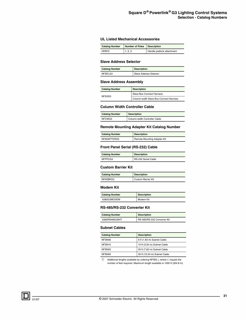
UL Listed Mechanical Accessories
Catalog Number Number of Poles Description
HPAFD 1, 2, 3 Handle padlock attachment
Slave Address Selector
Catalog Number Description
NFSELG3 Slave Address Selector
Slave Address Assembly
Catalog Number Description
NF2HG3Slave Bus Connect Harness
Column-width Slave Bus Connect Harness
Column Width Controller Cable
Catalog Number Description
NFCWG3 Column-width Controller Cable
Remote Mounting Adapter Kit Catalog Number
Catalog Number Description
NFADAPTERG3 Remote Mounting Adapter Kit
Front Panel Serial (RS-232) Cable
Catalog Number Description
NFFPCG3 RS-232 Serial Cable
Custom Barrier Kit
Catalog Number Description
NFASBKG3 Custom Barrier Kit
Modem Kit
Catalog Number Description
6382G3MODEM Modem Kit
RS-485/RS-232 Converter Kit
Catalog Number Description
6382RS485G3KIT RS-485/RS-232 Converter Kit
Subnet Cables
Catalog Number Description
NFSN06 6 ft (1.83 m) Subnet Cable
NFSN10 10 ft (3.05 m) Subnet Cable
NFSN25 25 ft (7.62 m) Subnet Cable
NFSN50 50 ft (15.24 m) Subnet Cable
➀ Additional lengths available by ordering NFSN( ), where ( ) equals the number of feet required. Maximum length available is 1000 ft (304.8 m).
31© 2007 Schneider Electric All Rights Reserved
Square D® Powerlink® G3 Lighting Control SystemsSystem Component Standards
32
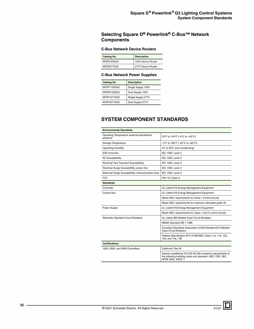
Selecting Square D® Powerlink® C-Bus™ Network Components
SYSTEM COMPONENT STANDARDS
C-Bus Network Device Routers
Catalog No. Description
NFDR120G3C 120V Device Router
NFDR277G3C 277V Device Router
C-Bus Network Power Supplies
Catalog No. Description
NFDP1120G3C Single Supply 120V
NFDP2120G3C Dual Supply 120V
NFDP1277G3C Single Supply 277V
NFDP2277G3C Dual Supply 277V
Environmental Standards
Operating Temperature (external panelboard ambient)
23°F to 104°F (–5°C to +40°C)
Storage Temperature –4°F to 185°F (–20°C to +85°C)
Operating Humidity 5% to 95% (non-condensing)
ESD Immunity IEC 1000, Level 4
RF Susceptibility IEC 1000, Level 3
Electrical Fast Transient Susceptibility IEC 1000, Level 3
Electrical Surge Susceptibility, power line IEC 1000, Level 4
Electrical Surge Susceptibility, interconnection lines IEC 1000, Level 3
FCC Part 15, Class A
Standards
Controller UL Listed 916 Energy Management Equipment
Control Bus UL Listed 916 Energy Management Equipment
Meets NEC requirements for Class 1 control circuits
Meets NEC requirements for maximum allowable gutter fill
Power Supply UL Listed 916 Energy Management Equipment
Meets NEC requirements for Class 1 and 2 control circuits
Remotely Operated Circuit Breakers UL Listed 489 Molded Case Circuit Breakers
NEMA Standard AB-1-1986
Canadian Standards Association (CSA) Standard 22.5 Molded Case Circuit Breakers
Federal Specification W-C-375B/GEN, Class 11a, 11b; 12a, 12b; and 13a, 13b
Certifications
1000, 2000, and 3000 Controllers California Title 24
Seismic qualified by ICC ES AC156 to seismic requirements of the following building codes and standard: UBC, CBC, IBC, NFPA 5000, ASCE 7
© 2007 Schneider Electric All Rights Reserved 01/07
Square D® Powerlink® G3 Lighting Control SystemsWiring Diagrams
01/07
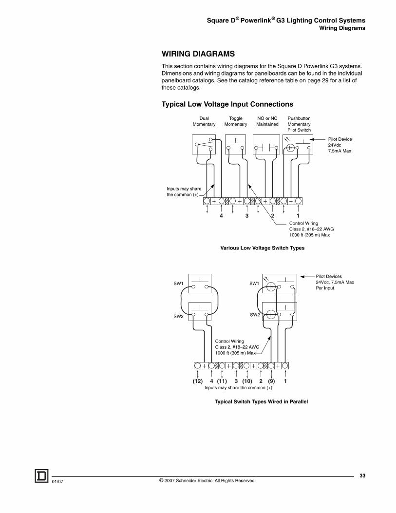
WIRING DIAGRAMS
This section contains wiring diagrams for the Square D Powerlink G3 systems. Dimensions and wiring diagrams for panelboards can be found in the individual panelboard catalogs. See the catalog reference table on page 29 for a list of these catalogs.
Typical Low Voltage Input Connections
1234
DualMomentary
Toggle Momentary
NO or NCMaintained
Pushbutton MomentaryPilot Switch
Pilot Device24Vdc 7.5mA Max
Inputs may share the common (+)
Control Wiring Class 2, #18–22 AWG1000 ft (305 m) Max
Various Low Voltage Switch Types
234(12) (11) (10) (9) 1
SW1
Inputs may share the common (+)
Control Wiring Class 2, #18–22 AWG1000 ft (305 m) Max
Typical Switch Types Wired in Parallel
SW2 SW2
SW1
Pilot Devices24Vdc, 7.5mA Max Per Input
33© 2007 Schneider Electric All Rights Reserved
Square D® Powerlink® G3 Lighting Control SystemsWiring Diagrams
34
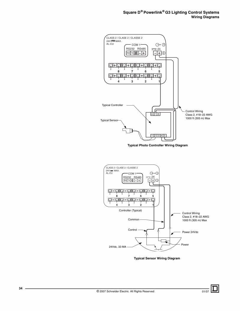
1234
5678
6 7 8
1 2 3 4 5
CLASS 2 / CLASE 2 / CLASSE 224V MAX.AL-CU COM 1
RS232
RX TX
RS485 24
Typical Photo Controller Wiring Diagram
Control Wiring Class 2, #18–22 AWG1000 ft (305 m) Max
Typical Controller
Typical Sensor
1234
5678
COM 1
RS232RX TX
RS485
CLASS 2 / CLASE 2 / CLASSE 224V MAX.AL-CU
24
Typical Sensor Wiring Diagram
Control Wiring Class 2, #18–22 AWG1000 ft (305 m) Max
Controller (Typical)
Power 24Vdc
Common
Control
24Vdc, 33 MAPower
© 2007 Schneider Electric All Rights Reserved 01/07
Square D® Powerlink® G3 Lighting Control SystemsWiring Diagrams
01/07
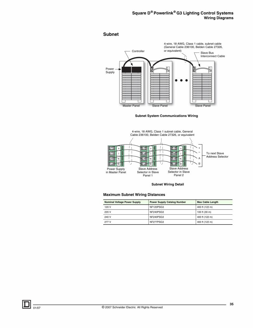
Subnet
Maximum Subnet Wiring Distances
Nominal Voltage Power Supply Power Supply Catalog Number Max Cable Length
120 V NF120PSG3 400 ft (122 m)
220 V NF240PSG3 100 ft (30 m)
240 V NF240PSG3 400 ft (122 m)
277 V NF277PSG3 400 ft (122 m)
4-wire, 18 AWG, Class 1 cable, subnet cable(General Cable 236100, Belden Cable 27326, or equivalent)
Master Panel Slave Panel Slave Panel
Controller
Power Supply
Slave Bus Interconnect Cable
Subnet System Communications WiringA
B–
+
A
B
–+
AB
–+
AB
–+
Power Supply in Master Panel
Slave Address Selector in Slave
Panel 1
Slave Address Selector in Slave
Panel 2
4-wire, 18 AWG, Class 1 subnet cable, General Cable 236100, Belden Cable 27326, or equivalent
To next Slave Address Selector
Subnet Wiring Detail
35© 2007 Schneider Electric All Rights Reserved
Square D® Powerlink® G3 Lighting Control SystemsWiring Diagrams
36
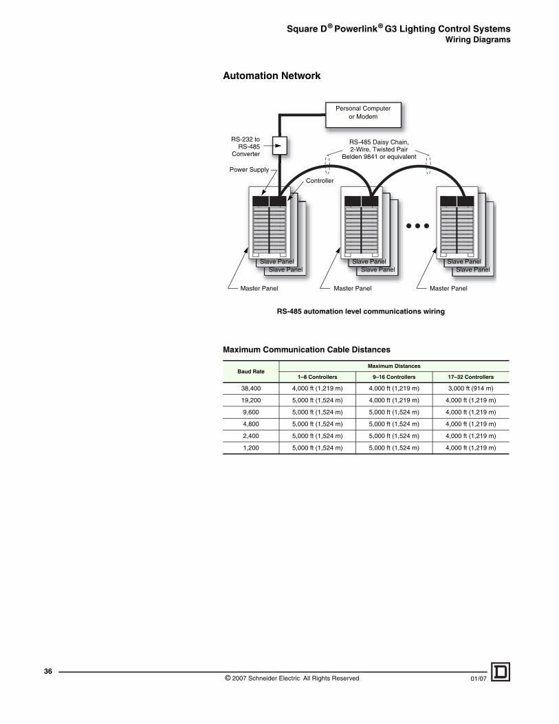
Automation Network
Maximum Communication Cable Distances
Baud RateMaximum Distances
1–8 Controllers 9–16 Controllers 17–32 Controllers
38,400 4,000 ft (1,219 m) 4,000 ft (1,219 m) 3,000 ft (914 m)
19,200 5,000 ft (1,524 m) 4,000 ft (1,219 m) 4,000 ft (1,219 m)
9,600 5,000 ft (1,524 m) 5,000 ft (1,524 m) 4,000 ft (1,219 m)
4,800 5,000 ft (1,524 m) 5,000 ft (1,524 m) 4,000 ft (1,219 m)
2,400 5,000 ft (1,524 m) 5,000 ft (1,524 m) 4,000 ft (1,219 m)
1,200 5,000 ft (1,524 m) 5,000 ft (1,524 m) 4,000 ft (1,219 m)
RS-232 toRS-485
Converter
Power Supply
Master Panel Master Panel Master Panel
Personal Computeror Modem
RS-485 Daisy Chain, 2-Wire, Twisted Pair
Belden 9841 or equivalent
Slave Panel Slave Panel Slave Panel Slave Panel Slave Panel Slave Panel
Controller
RS-485 automation level communications wiring
© 2007 Schneider Electric All Rights Reserved 01/07
Square D® Powerlink® G3 Lighting Control SystemsWiring Diagrams
01/07
RS-485 Converter
Ground shield in one place only.
RS-232 Female DB-9
Serial cable
RS-232 Female
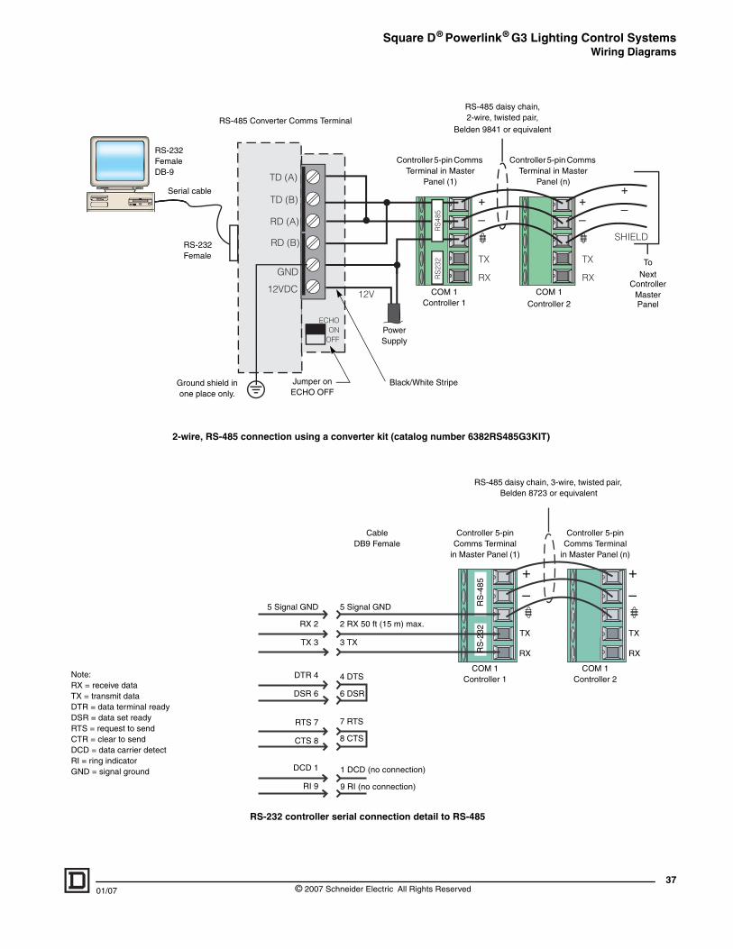
2-wire, RS-485 connection
RS-232 c
5 Sign
Note:RX = receive dataTX = transmit dataDTR = data terminal readyDSR = data set readyRTS = request to sendCTR = clear to sendDCD = data carrier detectRI = ring indicatorGND = signal ground
Black/White Stripe
Power Supply
RS-485 daisy chain, 2-wire, twisted pair,
Belden 9841 or equivalent
To Next
ControllerMaster Panel
Comms Terminal
Controller 5-pin Comms Terminal in Master
Panel (n)
Controller 5-pin Comms Terminal in Master
Panel (1)
Jumper on ECHO OFF
using a converter kit (catalog number 6382RS485G3KIT)
COM 1 Controller 1
COM 1Controller 2
ontroller serial connection detail to RS-485
RS-485 daisy chain, 3-wire, twisted pair, Belden 8723 or equivalent
Controller 5-pin Comms Terminal
in Master Panel (n)
Controller 5-pin Comms Terminal
in Master Panel (1)
COM 1Controller 2
COM 1 Controller 1
1 DCD (no connection)
9 RI (no connection)
7 RTS
8 CTS
4 DTS
6 DSR
5 Signal GND
2 RX 50 ft (15 m) max.
3 TX
al GND
RX 2
TX 3
DTR 4
DSR 6
RTS 7
CTS 8
DCD 1
RI 9
Cable DB9 Female
+
RX
TX
RX
+
– –
RS
-485
RS
-232 TX
37© 2007 Schneider Electric All Rights Reserved
Square D® Powerlink® G3 Lighting Control SystemsWiring Diagrams
38
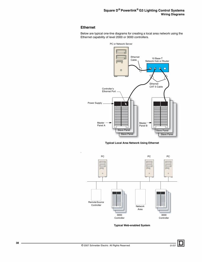
Ethernet
Below are typical one-line diagrams for creating a local area network using the Ethernet capability of level 2000 or 3000 controllers.
.
Power Supply
Master Panel A
Master Panel B
Slave Panel
Slave Panel
Slave Panel
Slave Panel
PC or Network Server
10 Base-TNetwork Hub or Router
Controller’s Ethernet Port
EthernetCAT 5 Cable
Ethernet Cable
Typical Local Area Network Using Ethernet
PC PC
3000 Controller
3000 Controller
Network Area
Remote Source Controller
PC
Typical Web-enabled System
© 2007 Schneider Electric All Rights Reserved 01/07
Square D® Powerlink® G3 Lighting Control SystemsWiring Diagrams
01/07
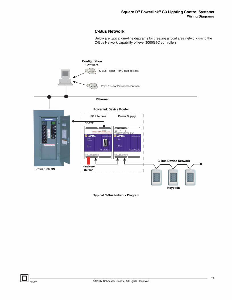
C-Bus CO
UnitComm
C-Bus
P
Powerlink G3
ConfigSoft
RS-23
HardwaBurde
C-Bus Network
Below are typical one-line diagrams for creating a local area network using the C-Bus Network capability of level 3000G3C controllers.
NUSE COPPER WIRE ONLY
Power Supply
Lighting Control
C-Bus CONNECTIONS
L
Unit
C-Bus
WARNING: DO NOT CONNECT C-BUS NETWORK TO PC COMM PORT (RS232)
PC Interface
Lighting Control
RS
-232
RS-232
NNECTIONS
s
Keypads
C-Bus Device Network
C Interface Power Supply
uration ware
2
Ethernet
Powerlink Device Router
C-Bus Toolkit—for C-Bus devices
PCS101—for Powerlink controller
re n
Typical C-Bus Network Diagram
39© 2007 Schneider Electric All Rights Reserved
Schneider Electric295 Tech Park DriveLaVergne, TN 37086 USA1-888-Square D (1-888-778-2738)1-615-287-3400 www.squaredlightingcontrol.com
1210CT0201R1/07
Square D® Powerlink® G3 Lighting Systems
Catalog
Listed products must be installed/connected by licensed professionals only and used in compliance with applicable industry standards and/or installation regulations.
As standards, specifications, and designs change from time to time, please ask for confirmation of the information given in this publication.
Publishing: Square D Company Lighting Control BusinessProduction: Square D Company Lighting Control Business
01/2007 © 2005 Schneider Electric All Rights ReservedCatalog No. 1210CT0201R1/07 Replaces 1210CT0001R4/05 and all previous versions