Embed Size (px)
Citation preview

File: Reeve_SquareLoopAntenna1.2m.doc, Page 1
Square VLF Loop Antenna, 1.2 m Diagonal~ Mechanical and Electrical Characteristics and Construction Details ~
Whitham D. Reeve
1. Dimensions
The loop antenna described here has a square shape with a diagonal length of 1.207 m. The loop is made fromfiberglass framework and marine plywood braces and consists of 64 ±1 turns of 18 AWG coated magnet wire.
The width of a square in terms of its diagonal length is
lW 2
2Eq. (1.1)
whereW = square widthl = diagonal length (1.207 m)
The perimeter length of a square is
Wp 4 Eq. (1.2)
wherep = perimeter length
Therefore, for the loop in question
21.207
2W 0.853 m = 85.3 cm
4 0.853p 3.412 m
The enclosed area of a square is
2WA (0.0.853)2 = 0.733 m2 Eq. (1.3)
whereA = enclosed area of square
The loop is wound with 18 AWG magnet wire, which has a coated nominal diameter of approximately 0.0424 in.= 1.077 mm = 0.1077 cm and uncoated nominal diameter of 0.0403 in. = 1.0236 mm = 0.1024 cm.
The total wire length is3.412 64 218.4Length p T m
whereT = Number of turns

File: Reeve_SquareLoopAntenna1.2m.doc, Page 2
File: Reeve_SquareLoopAntenna1.2m.doc, Page 3
2. Inductance
Four methods are investigated for calculating the loop inductance. All methods are estimates and none perfectlyfit the actual antenna construction but method 1 is the closest. The coil cross-section on the actual antenna ismore or less rectangular, but two of the methods assume a flat, single-layer cross-section. The formulas usedhere are based on a 1937 National Bureau of Standards document in which the CGS unit system is used. To avoidunits conversion errors, all calculations given here use the same units. Also included are actual measurementsfor comparison with calculations.
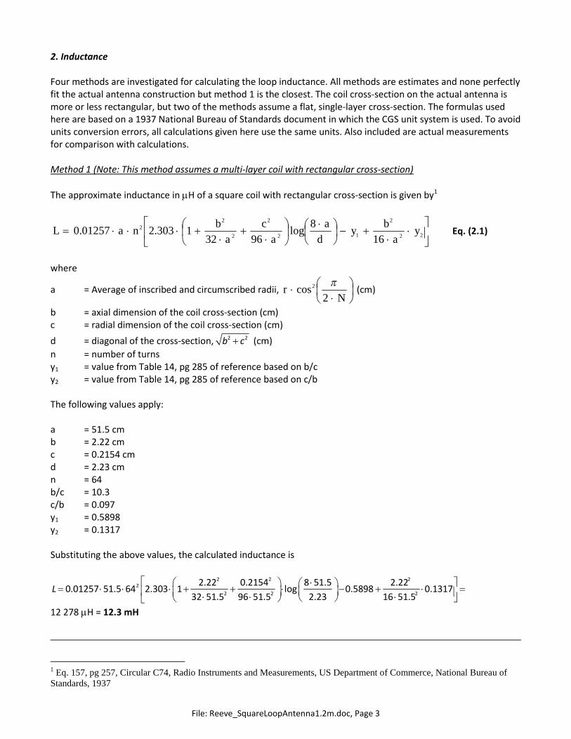
Method 1 (Note: This method assumes a multi-layer coil with rectangular cross-section)
The approximate inductance in H of a square coil with rectangular cross-section is given by1
22
2
12
2
2
2
2
16
8log
96321303.201257.0 y
a
by
d
a
a
c
a
bnaL Eq. (2.1)
where
a = Average of inscribed and circumscribed radii,
Nr
2cos2
(cm)
b = axial dimension of the coil cross-section (cm)c = radial dimension of the coil cross-section (cm)
d = diagonal of the cross-section, 2 2b c (cm)
n = number of turnsy1 = value from Table 14, pg 285 of reference based on b/cy2 = value from Table 14, pg 285 of reference based on c/b
The following values apply:
a = 51.5 cmb = 2.22 cmc = 0.2154 cmd = 2.23 cmn = 64b/c = 10.3c/b = 0.097y1 = 0.5898y2 = 0.1317
Substituting the above values, the calculated inductance is
2 2 22
2 2 2
2.22 0.2154 8 51.5 2.220.01257 51.5 64 2.303 1 log 0.5898 0.1317
32 51.5 96 51.5 2.23 16 51.5L
12 278 H = 12.3 mH
1 Eq. 157, pg 257, Circular C74, Radio Instruments and Measurements, US Department of Commerce, National Bureau ofStandards, 1937
File: Reeve_SquareLoopAntenna1.2m.doc, Page 4
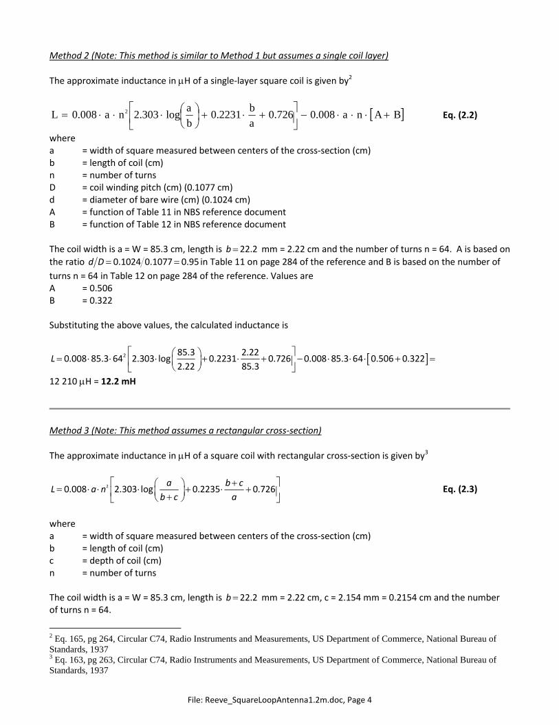
Method 2 (Note: This method is similar to Method 1 but assumes a single coil layer)
The approximate inductance in H of a single-layer square coil is given by2
BAnaa
b
b
anaL
008.0726.02231.0log303.2008.0 2 Eq. (2.2)
wherea = width of square measured between centers of the cross-section (cm)b = length of coil (cm)n = number of turnsD = coil winding pitch (cm) (0.1077 cm)d = diameter of bare wire (cm) (0.1024 cm)A = function of Table 11 in NBS reference documentB = function of Table 12 in NBS reference document
The coil width is a = W = 85.3 cm, length is 22.2b mm = 2.22 cm and the number of turns n = 64. A is based on
the ratio 0.1024 0.1077 0.95d D in Table 11 on page 284 of the reference and B is based on the number of
turns n = 64 in Table 12 on page 284 of the reference. Values areA = 0.506B = 0.322
Substituting the above values, the calculated inductance is
2 85.3 2.220.008 85.3 64 2.303 log 0.2231 0.726 0.008 85.3 64 0.506 0.322
2.22 85.3L
12 210 H = 12.2 mH
Method 3 (Note: This method assumes a rectangular cross-section)
The approximate inductance in H of a square coil with rectangular cross-section is given by3
20.008 2.303 log 0.2235 0.726a b c
L a nb c a
Eq. (2.3)
wherea = width of square measured between centers of the cross-section (cm)b = length of coil (cm)c = depth of coil (cm)n = number of turns
The coil width is a = W = 85.3 cm, length is 22.2b mm = 2.22 cm, c = 2.154 mm = 0.2154 cm and the numberof turns n = 64.
2 Eq. 165, pg 264, Circular C74, Radio Instruments and Measurements, US Department of Commerce, National Bureau ofStandards, 19373 Eq. 163, pg 263, Circular C74, Radio Instruments and Measurements, US Department of Commerce, National Bureau ofStandards, 1937

File: Reeve_SquareLoopAntenna1.2m.doc, Page 5
Substituting the above values, the calculated inductance is
2 85.3 2.22 0.21540.008 85.3 64 2.303 log 0.2231 0.726
2.22 0.2154 85.3L
= 11 990 H = 12.0 mH
Method 4 (Note: this method assumes a single-layer coil of length b of polygon shape)
The approximate inductance in H of a polygon is given by4
2 20.03948 a nL K
b
μH Eq. (2.4)
where
a = Average of inscribed and circumscribed radii, 2cos2
rN
(cm) Eq. (2.5)
r = radius of circumscribed circle (cm)N = number of sides (4 for a square)n = number of turns
b = length of coil, or dn (cm)d = distance between turn centers = wire diameter for close spacing (cm) (0.1077 cm for 18 AWG coated
wire)
K = function of ba /2 from table 10 in the reference NBS document
The radius of a circumscribed circle for a square is
1.207
2 22
W lr 0.6033 m = 60.33 cm Eq. (2.6)
and the average of the inscribed and circumscribed radii is
260.33 cos2 4
a
51.5 cm
The estimated coil length for single-layer flat winding is 62 0.1077 6.68b n d cm. K is based on2 / 2 51.5 / 6.68 15.42a b and is found in Table 10, page 283 of the reference NBS document by
interpolation, or
K = 0.1498.
Substituting the above values, the calculated inductance is
2 20.03948 51.5 640.1498
6.68L
9 618 H = 9.6 mH
4 Eq. 153, pg 252, Circular C74, Radio Instruments and Measurements, US Department of Commerce, National Bureau ofStandards, 1937
File: Reeve_SquareLoopAntenna1.2m.doc, Page 6
3. Measurements
Measurement date: 10 August 2018
Measured inductance at 15.5 °C:
DM4070: 12.29 mH
Peak LCR45: 12.24 mH at 1 kHz
Peak LCR45: 13.65 mH at 15 kHz
Peak LCR45: 680 uH at 200 kHz
Measurement date: 2 September 2018 (on-site)
Measured inductance at 15.0 °C:
Keysight U1733C: 12.270 mH, Q = 16.7 at 1 kHz
Keysight U1733C: 12.841 mH, Q = 69.1 at 10 kHz
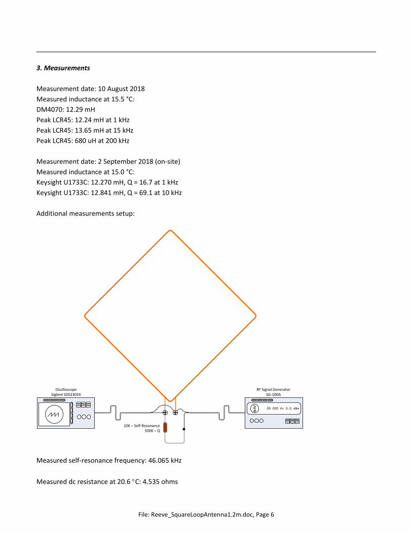
Additional measurements setup:
10K – Self-Resonance500K – Q
OscilloscopeSiglent SDS2302X
RF Signal GeneratorSG-100A
00 000 Hz 0.0 dBm
Measured self-resonance frequency: 46.065 kHz
Measured dc resistance at 20.6 C: 4.535 ohms

File: Reeve_SquareLoopAntenna1.2m.doc, Page 7
Calculated dc resistance: 6.386 ohms/1000 ft x 3.412 m x 64 / 0.3048 = 4.5751 ohms at 20 C
Calculated distributed capacitance, Cd , based on self-resonance: 1020 pF
Peak voltage at resonance: 0.4118 V, 6 dBV reduction: 0.4118 V x 0.707 = 0.2911 V
Frequencies at 6 dBV reduction (–3 dB power): 38 173 and 55 523 Hz, Frequency change = 3 dB power
bandwidth: 17 350 Hz
The loop originally was built in late 2009 using a 1200 ft spool of 18 AWG coated magnet wire resulting in 96 ±1
turns. The average individual winding length was approximately 11.25 ft (3.43 m). After construction I made a
series of inductance and self-resonant frequency measurements as follows:
Instrument: TH2811D, Temperature: 20.6 °C
Test Frequency (Hz) Inductance (μH) Q R (ohms)100 27.126 2.4942 6.8364120 27.117 2.9865 6.8438
1000 27.116 23.9 7.1410000 30.581 70 27.6Calculated 27.625 N/A 6.8627
I measured the self-resonant frequency at 28.4 kHz but this was much too low for applications as a tuned loop
for VLF and LF applications. I then removed one turn at a time and measured the inductance and self-resonant
frequency after each turn was removed. I removed 32 turns to achieve the desired self-resonant frequency of
45.6 kHz. See chart below.
y = 0.4506x + 31.312
y = -0.4638x + 26.348
0
5
10
15
20
25
30
35
40
45
50
0 5 10 15 20 25 30 35
Ind
uct
ance
(μH
)o
rR
eso
na
nt
Fre
qu
en
cy(k
Hz)
Number of Turns Removed
1.2 m Square Loop Measurements ~ Turns Removal
Resonant Frequency
Inductance
Linear (Resonant Frequency)
Linear (Inductance)
File: Reeve_SquareLoopAntenna1.2m.doc, Page 8
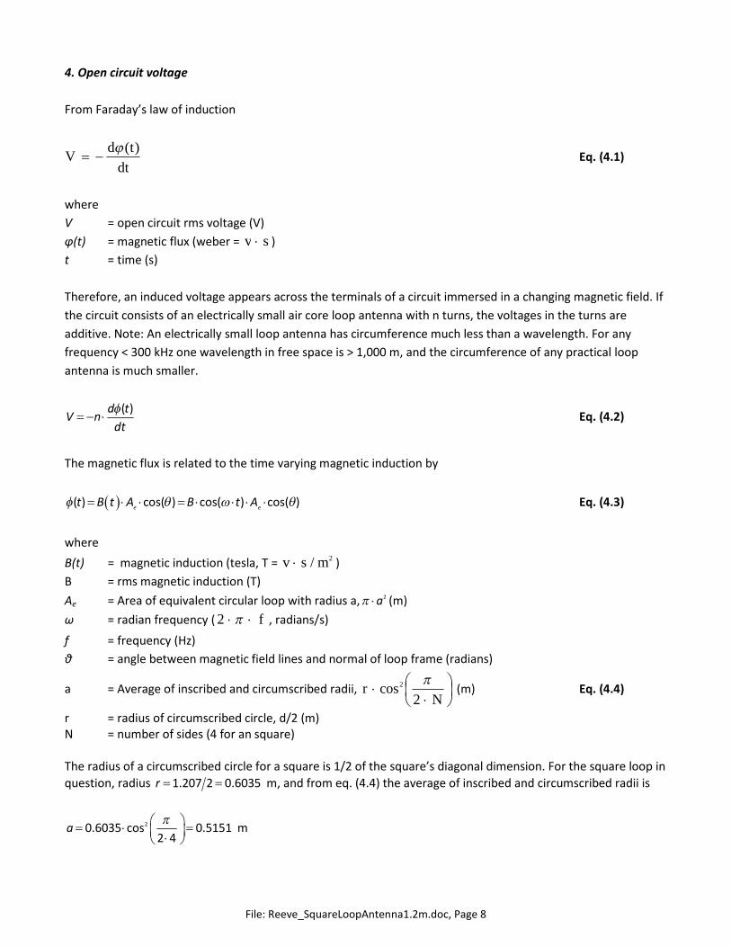
4. Open circuit voltage
From Faraday’s law of induction
dt
tdV
)( Eq. (4.1)
where
V = open circuit rms voltage (V)
φ(t) = magnetic flux (weber = sv )
t = time (s)
Therefore, an induced voltage appears across the terminals of a circuit immersed in a changing magnetic field. If
the circuit consists of an electrically small air core loop antenna with n turns, the voltages in the turns are
additive. Note: An electrically small loop antenna has circumference much less than a wavelength. For any
frequency < 300 kHz one wavelength in free space is > 1,000 m, and the circumference of any practical loop
antenna is much smaller.
( )d tV n
dt
Eq. (4.2)
The magnetic flux is related to the time varying magnetic induction by
( ) cos( ) cos( ) cos( )e e
t B t A B t A Eq. (4.3)
where
B(t) = magnetic induction (tesla, T = 2/ msv )
B = rms magnetic induction (T)
Ae = Area of equivalent circular loop with radius a, 2a (m)
ω = radian frequency ( f 2 , radians/s)
f = frequency (Hz)
θ = angle between magnetic field lines and normal of loop frame (radians)
a = Average of inscribed and circumscribed radii,
Nr
2cos2
(m) Eq. (4.4)
r = radius of circumscribed circle, d/2 (m)N = number of sides (4 for an square)
The radius of a circumscribed circle for a square is 1/2 of the square’s diagonal dimension. For the square loop in
question, radius 1.207 2 0.6035r m, and from eq. (4.4) the average of inscribed and circumscribed radii is
20.6035 cos 0.51512 4
a
m

File: Reeve_SquareLoopAntenna1.2m.doc, Page 9
Therefore, for the square loop in question, the equivalent area 2 20.5151 0.8336e
A a m2
Differentiating Eq. (4.3) gives
( ) ( ) cos( )
cos( ) cos( ) cos sine e e
d t dB t d tA B A B A t
dt dt dt
Eq. (4.5)
Substituting Eq. (4.5) in Eq. (4.1), the open circuit voltage across the loop terminal is
2 cos sine
V t f n A B t
and the open circuit rms voltage is
2 cose
V f n A B Eq. (4.6)
The above expression indicates the loop antenna responds to the magnetic field component (magnetic induction
or flux density, B) of a signal and converts it to a voltage at the antenna terminals.
The voltage at the terminals is related to the electric field strength, E, by
EhV e Eq. (4.7)
where
he = effective antenna height (m)
E = rms electric field strength (V/m)
The relationship between the electric field strength and magnetic induction is
BcE Eq. (4.8)
where
c = speed of light in free space ( 8103 m/s)
Substituting Eq. (4.6), (4.7) and (4.8), the effective height of an air-core loop is
cos2cos2
ee
e
An
c
Anfh Eq. (4.9)
where
λ = wavelength (m)
It is seen from eq. (4.7) that, for a given electric field strength, the rms voltage at the loop terminals is
proportional to the effective height. Equivalently, from eq. (4.9) it is proportional to the frequency, number of

File: Reeve_SquareLoopAntenna1.2m.doc, Page 10
turns and loop equivalent area. Note that the effective height is not related to the physical height of the loop –
it relates the field strength to open circuit voltage. For a given frequency the effective height can be increased
by increasing the number of turns or loop area.
For the case where the loop frame is parallel to the propagation direction and the magnetic field is normal to
the propagation direction, in which case θ = 0 deg. = 0 radians, eq. (4.9) becomes
2e
e
n A fh
c
Eq. (4.10)
If the frequency is 24 kHz, the effective height of the example antenna is
3
8
2 2 64 0.8336 24 100.0268
3 10e
e
n A fh
c
m
If the field strength is 500 v/m at 24 kHz, the open circuit (unloaded) loop terminal voltage for the example
loop is
0.0268 500 13.4e
V h E V
In air and free space, the magnetic field strength and magnetic induction are related by
0
BH Eq. (4.11)
where
H = rms magnetic field strength (a/m)
0 = permeability of air or free space (4π x 10-7 henry/m)
Therefore, when the loop frame is parallel to the line of signal propagation, the rms loop terminal voltage is
maximum and in term of the magnetic field strength is given by
max 02V n A f H Eq. (4.12)

File: Reeve_SquareLoopAntenna1.2m.doc, Page 11
5. Construction images
The loop was constructed between 28 November and 6 December 2009.
1” square fiberglass tube was used for theloop frame or cross-braces. The loopdimensions were determined by the length ofthe 8 ft tube I had on-hand; it was simply cutin half. The braces were cut on a table sawwith an abrasive blade used for cutting metal.The center of each brace was then notchedon the saw so they fit together at the center.
The ends of each brace were cut at 45 angleon the table saw and lightly sanded. Thenotched ends hold the wire in place.

File: Reeve_SquareLoopAntenna1.2m.doc, Page 12
The two braces fit together at their centers.
Reinforcements were cut from 1/4” marineplywood with a 6” hole saw on a drill pressand then cut into pieces on a table saw.
After sanding the reinforcements, they wereclamped to the braces to ensure alignmentand drilled with a 3/16 in brad point drill. Thefasteners are 18-8 stainless steel 10-32machine screws, washers and nuts. After thisimage was taken, the wood pieces wereremoved and painted with urethane sparvarnish.

File: Reeve_SquareLoopAntenna1.2m.doc, Page 13
After parts were permanently assembled, theloop frame was clamped to a wood plate witha mandrel on then placed on a shop table forwinding. The spool of magnet wire wasplaced on another mandrel clamped to anadjacent table.
The starting end of the 18 AWG coatedmagnet wire was clamped to the frame andthen the frame was slowly rotated.
Completed loop antenna with 96 turns andabout 1100 ft of wire. 32 turns were laterremoved as discussed in the measurementssection leaving about 720 ft on completedantenna.
File: Reeve_SquareLoopAntenna1.2m.doc, Page 14
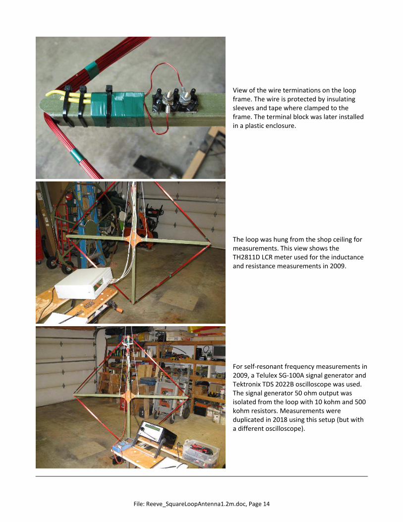
View of the wire terminations on the loopframe. The wire is protected by insulatingsleeves and tape where clamped to theframe. The terminal block was later installedin a plastic enclosure.
The loop was hung from the shop ceiling formeasurements. This view shows theTH2811D LCR meter used for the inductanceand resistance measurements in 2009.
For self-resonant frequency measurements in2009, a Telulex SG-100A signal generator andTektronix TDS 2022B oscilloscope was used.The signal generator 50 ohm output wasisolated from the loop with 10 kohm and 500kohm resistors. Measurements wereduplicated in 2018 using this setup (but witha different oscilloscope).

File: Reeve_SquareLoopAntenna1.2m.doc, Page 15
Author - Whitham Reeve is a contributing editor for the SARA journal, Radio Astronomy.He obtained B.S. and M.S. degrees in Electrical Engineering at University of AlaskaFairbanks, USA. He worked as a professional engineer and engineering firmowner/operator in the airline and telecommunications industries for more than 40 yearsand now manufactures electronic equipment used in radio astronomy. He has lived inAnchorage, Alaska his entire life. Email contact: [email protected]
File: Reeve_SquareLoopAntenna1.2m.doc, Page 16
Author: Whitham D. Reeve, Anchorage, Alaska USA
Copyright: © 2018 W. Reeve
Revision: 0.0 (Initial draft based on UKRAA loop write-up, 11 Jun 2018)
0.1 (Substituted actual values for calculations, 06 Aug 2018)
0.2 (Added measurements, 11 Aug 2018)
0.3 (Updated calculations, 15 Aug 2018)
0.4 (Completed 1st draft for distribution, 20 Aug 2018)
0.5 (Added original construction images and data, 21 Aug 2018)
0.6 (Added open circuit voltage calculations, 23 Aug 2018)
0.7 (Added U1733C on-site measurements, 04 Sep 2018)
0.8 (Minor updates to construction section, 07 Sep 2018)
0.9 (Added wire length, 12 Sep 2018)
Word count: 2355File size (bytes): 811520