Embed Size (px)
Citation preview
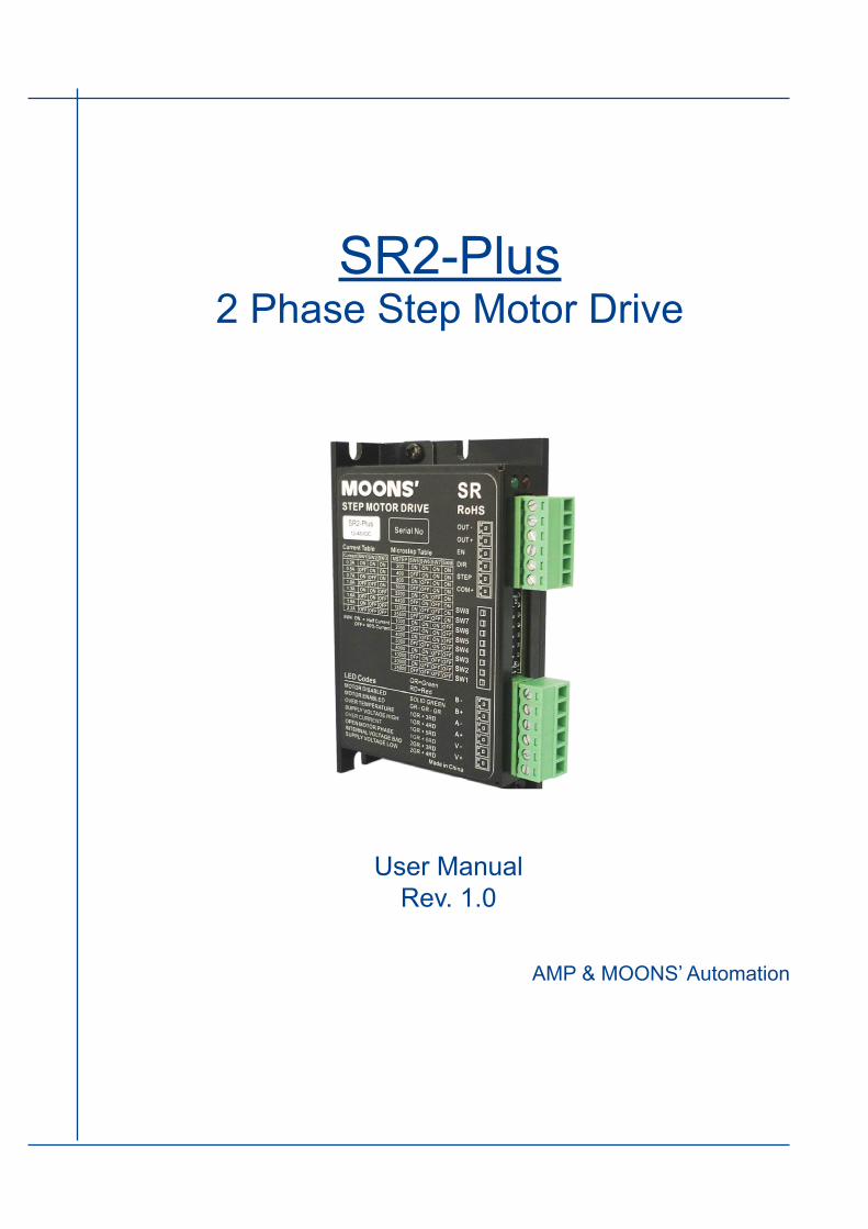
SR2-Plus2 Phase Step Motor Drive
User ManualRev. 1.0
AMP & MOONS’ Automation
Rev. 1.05/14/2012 2
SR2-Plus User Manual
Contents1 Introduction .................................................................................. 3
1.1 Overview ............................................................................................31.2 Features .............................................................................................31.3 Block diagram ....................................................................................4
2 Mounting the Drive ...................................................................... 43 Connections ................................................................................ 5
3.1 Connector Diagram ............................................................................53.2 Connecting to the Power Supply .......................................................53.3 Connecting to a Motor .......................................................................63.4 Connecting the I/O .............................................................................6
3.4.1 Step & Direction Inputs ................................................................................63.4.2 EN input .......................................................................................................63.4.3 Fault Output .................................................................................................7
4 Switch Selecting .......................................................................... 84.1 Running Current ................................................................................84.2 Idle Current ........................................................................................84.3 Microstepping ....................................................................................94.4 Self test ..............................................................................................94.5 Command Signal Smoothing ...........................................................104.6 Load Inertia ......................................................................................104.7 Digital Signal Filter ...........................................................................10
5 Motor Selection ......................................................................... 115.1 Recommended Motors .................................................................... 11
6 LED Error Codes ....................................................................... 137 Reference Materials .................................................................. 13
7.1 Mechanical Outline ..........................................................................137.2 Specifications ...................................................................................14
7.2.1 Electrical Specifications .............................................................................147.2.2 Environmental Specifications ....................................................................14
7.3 Torque Curves ..................................................................................158 Contacting MOONS’ ................................................................... 17
3 Rev:1.05/14/2012
SR2-Plus User Manual
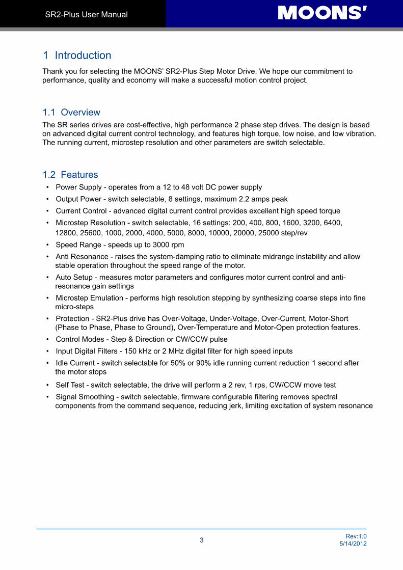
1 IntroductionThank you for selecting the MOONS’ SR2-Plus Step Motor Drive. We hope our commitment to performance, quality and economy will make a successful motion control project.
1.1 OverviewThe SR series drives are cost-effective, high performance 2 phase step drives. The design is based on advanced digital current control technology, and features high torque, low noise, and low vibration. The running current, microstep resolution and other parameters are switch selectable.
1.2 Features• Power Supply - operates from a 12 to 48 volt DC power supply• Output Power - switch selectable, 8 settings, maximum 2.2 amps peak• Current Control - advanced digital current control provides excellent high speed torque• Microstep Resolution - switch selectable, 16 settings: 200, 400, 800, 1600, 3200, 6400,
12800, 25600, 1000, 2000, 4000, 5000, 8000, 10000, 20000, 25000 step/rev • Speed Range - speeds up to 3000 rpm• Anti Resonance - raises the system-damping ratio to eliminate midrange instability and allow
stable operation throughout the speed range of the motor.• Auto Setup - measures motor parameters and configures motor current control and anti-
resonance gain settings• Microstep Emulation - performs high resolution stepping by synthesizing coarse steps into fine
micro-steps• Protection - SR2-Plus drive has Over-Voltage, Under-Voltage, Over-Current, Motor-Short
(Phase to Phase, Phase to Ground), Over-Temperature and Motor-Open protection features.• Control Modes - Step & Direction or CW/CCW pulse• Input Digital Filters - 150 kHz or 2 MHz digital filter for high speed inputs• Idle Current - switch selectable for 50% or 90% idle running current reduction 1 second after
the motor stops
• Self Test - switch selectable, the drive will perform a 2 rev, 1 rps, CW/CCW move test• Signal Smoothing - switch selectable, firmware configurable filtering removes spectral
components from the command sequence, reducing jerk, limiting excitation of system resonance
Rev. 1.05/14/2012 4
SR2-Plus User Manual
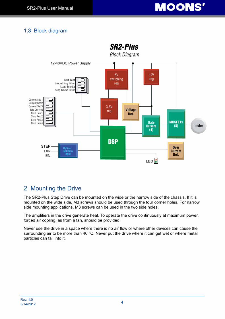
1.3 Block diagram
2 Mounting the DriveThe SR2-Plus Step Drive can be mounted on the wide or the narrow side of the chassis. If it is mounted on the wide side, M3 screws should be used through the four corner holes. For narrow side mounting applications, M3 screws can be used in the two side holes.
The amplifiers in the drive generate heat. To operate the drive continuously at maximum power, forced air cooling, as from a fan, should be provided.
Never use the drive in a space where there is no air flow or where other devices can cause the surrounding air to be more than 40 °C. Never put the drive where it can get wet or where metal particles can fall into it.
Block DiagramSR2-Plus
10Vreg
5Vswitching
reg
3.3Vreg Voltage
Det.
OverCurrent
Det.
motor
12-48VDC Power Supply
LED
STEPDIREN
Optical Isolation
Input
DSP
GateDrivers
(4)
MOSFETs(8)
Self TestSmoothing Filter
Load InertiaStep Noise Filter
Current Set 1Current Set 2Current Set 3
Idle CurrentStep Res 1Step Res 2Step Res 3Step Res 4
5 Rev:1.05/14/2012
SR2-Plus User Manual
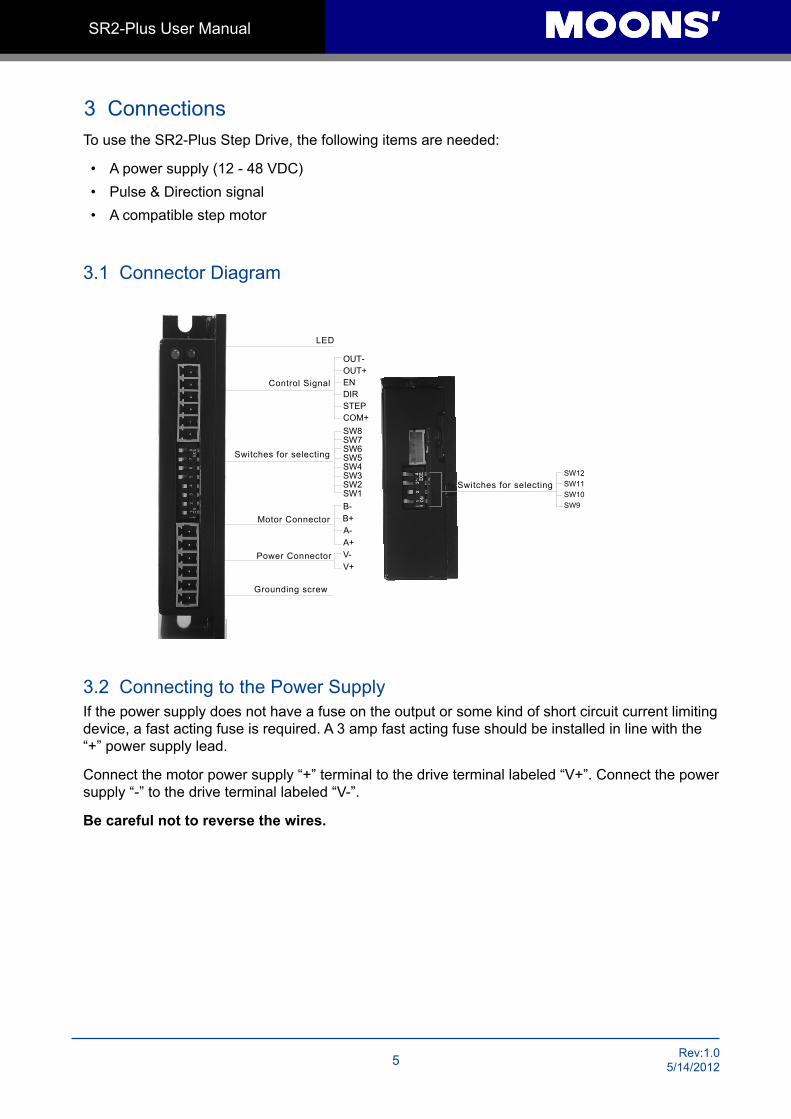
3 ConnectionsTo use the SR2-Plus Step Drive, the following items are needed:
• A power supply (12 - 48 VDC)• Pulse & Direction signal • A compatible step motor
3.1 Connector Diagram
3.2 Connecting to the Power SupplyIf the power supply does not have a fuse on the output or some kind of short circuit current limiting device, a fast acting fuse is required. A 3 amp fast acting fuse should be installed in line with the “+” power supply lead.
Connect the motor power supply “+” terminal to the drive terminal labeled “V+”. Connect the power supply “-” to the drive terminal labeled “V-”.
Be careful not to reverse the wires.
LED
Control Signal
Switches for selecting
Motor Connector
Power Connector
OUT-OUT+ENDIRSTEPCOM+
SW1 SW2 SW3 SW4 SW5 SW6 SW7 SW8
B- B+ A- A+ V- V+
Grounding screw
SW12SW11SW10SW9
Switches for selecting
Rev. 1.05/14/2012 6
SR2-Plus User Manual
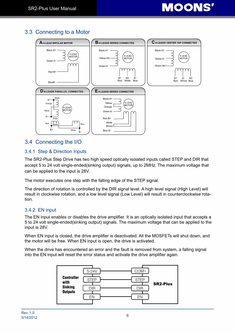
3.3 Connecting to a Motor
3.4 Connecting the I/O
3.4.1 Step & Direction InputsThe SR2-Plus Step Drive has two high speed optically isolated inputs called STEP and DIR that accept 5 to 24 volt single-ended(sinking output) signals, up to 2MHz. The maximum voltage that can be applied to the input is 28V.
The motor executes one step with the falling edge of the STEP signal.
The direction of rotation is controlled by the DIR signal level. A high level signal (High Level) will result in clockwise rotation, and a low level signal (Low Level) will result in counterclockwise rota-tion.
3.4.2 EN inputThe EN input enables or disables the drive amplifier. It is an optically isolated input that accepts a 5 to 24 volt single-ended(sinking output) signals. The maximum voltage that can be applied to the input is 28V.
When EN input is closed, the drive amplifier is deactivated. All the MOSFETs will shut down, and the motor will be free. When EN input is open, the drive is activated.
When the drive has encountered an error and the fault is removed from system, a falling signal into the EN input will reset the error status and activate the drive amplifier again.
EN
STEP
DIR
COM+
DIR
EN
5-24V
STEPSR2-Plus
ControllerwithSinkingOutputs
7 Rev:1.05/14/2012
SR2-Plus User Manual
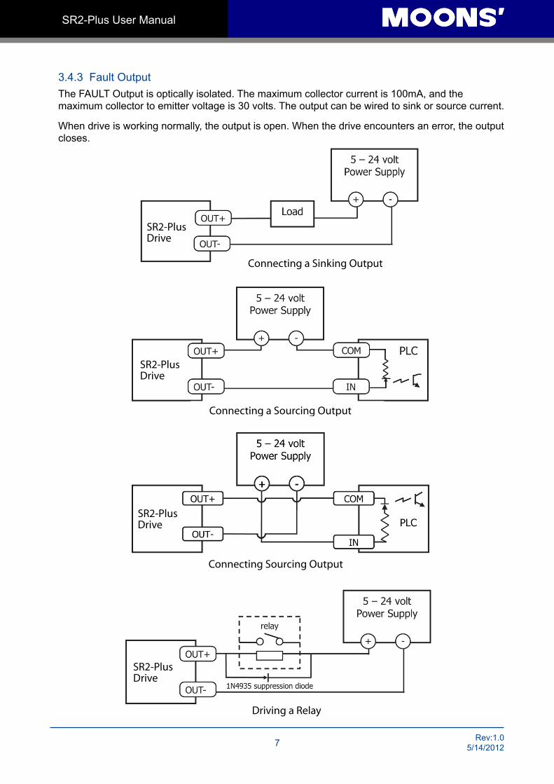
3.4.3 Fault OutputThe FAULT Output is optically isolated. The maximum collector current is 100mA, and the maximum collector to emitter voltage is 30 volts. The output can be wired to sink or source current.
When drive is working normally, the output is open. When the drive encounters an error, the output closes.
SR2-PlusDrive
Driving a Relay
SR2-PlusDrive
Connecting a Sinking Output
SR2-PlusDrive
Connecting a Sourcing Output
SR2-PlusDrive
Connecting Sourcing Output
Rev. 1.05/14/2012 8
SR2-Plus User Manual
4 Switch Selecting
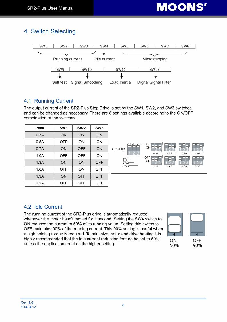
4.1 Running CurrentThe output current of the SR2-Plus Step Drive is set by the SW1, SW2, and SW3 switches and can be changed as necessary. There are 8 settings available according to the ON/OFF combination of the switches.
4.2 Idle CurrentThe running current of the SR2-Plus drive is automatically reduced whenever the motor hasn’t moved for 1 second. Setting the SW4 switch to ON reduces the current to 50% of its running value. Setting this switch to OFF maintains 90% of the running current. This 90% setting is useful when a high holding torque is required. To minimize motor and drive heating it is highly recommended that the idle current reduction feature be set to 50% unless the application requires the higher setting.
Peak SW1 SW2 SW3
0.3A ON ON ON
0.5A OFF ON ON
0.7A ON OFF ON
1.0A OFF OFF ON
1.3A ON ON OFF
1.6A OFF ON OFF
1.9A ON OFF OFF
2.2A OFF OFF OFF
SW1 SW2 SW3 SW4 SW5 SW6 SW7 SW8
Running current Idle current Microstepping
SW9 SW10 SW11 SW12
Self test Signal Smoothing Load Inertia Digital Signal Filter
ON50%
OFF90%
4 4
9 Rev:1.05/14/2012
SR2-Plus User Manual
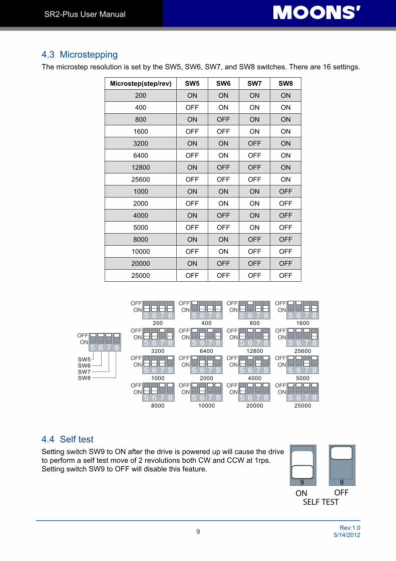
4.3 MicrosteppingThe microstep resolution is set by the SW5, SW6, SW7, and SW8 switches. There are 16 settings.
4.4 Self testSetting switch SW9 to ON after the drive is powered up will cause the drive to perform a self test move of 2 revolutions both CW and CCW at 1rps. Setting switch SW9 to OFF will disable this feature.
Microstep(step/rev) SW5 SW6 SW7 SW8
200 ON ON ON ON
400 OFF ON ON ON
800 ON OFF ON ON
1600 OFF OFF ON ON
3200 ON ON OFF ON
6400 OFF ON OFF ON
12800 ON OFF OFF ON
25600 OFF OFF OFF ON
1000 ON ON ON OFF
2000 OFF ON ON OFF
4000 ON OFF ON OFF
5000 OFF OFF ON OFF
8000 ON ON OFF OFF
10000 OFF ON OFF OFF
20000 ON OFF OFF OFF
25000 OFF OFF OFF OFF
ON SELF TEST
OFF9 9
Rev. 1.05/14/2012 10
SR2-Plus User Manual
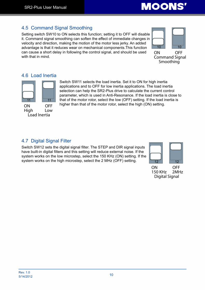
4.5 Command Signal SmoothingSetting switch SW10 to ON selects this function; setting it to OFF will disable it. Command signal smoothing can soften the effect of immediate changes in velocity and direction, making the motion of the motor less jerky. An added advantage is that it reduces wear on mechanical components.This function can cause a short delay in following the control signal, and should be used with that in mind.
4.6 Load InertiaSwitch SW11 selects the load inertia. Set it to ON for high inertia applications and to OFF for low inertia applications. The load inertia selection can help the SR2-Plus drive to calculate the current control parameter, which is used in Anti-Resonance. If the load inertia is close to that of the motor rotor, select the low (OFF) setting. If the load inertia is higher than that of the motor rotor, select the high (ON) setting.
4.7 Digital Signal FilterSwitch SW12 sets the digital signal filter. The STEP and DIR signal inputs have built-in digital filters and this setting will reduce external noise. If the system works on the low microstep, select the 150 KHz (ON) setting. If the system works on the high microstep, select the 2 MHz (OFF) setting.
ONCommand Signal Smoothing
OFF10 10
ONHigh Low Load Inertia
OFF11 11
ON150 KHz 2MHz Digital Signal
OFF12 12
11 Rev:1.05/14/2012
SR2-Plus User Manual
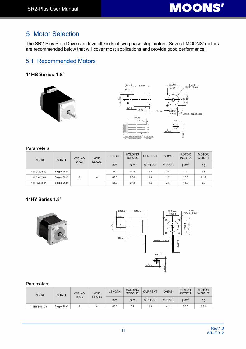
5 Motor SelectionThe SR2-Plus Step Drive can drive all kinds of two-phase step motors. Several MOONS’ motors are recommended below that will cover most applications and provide good performance.
5.1 Recommended Motors
11HS Series 1.8°
Parameters
PART# SHAFT WIRINGDIAG
#OF LEADS
LENGTH HOLDINGTORQUE CURRENT OHMS ROTOR
INERTIAMOTOR WEIGHT
mm N·m A/PHASE Ω/PHASE g·cm2 Kg
11HS1008-07 Single Shaft
A 4
31.0 0.05 1.6 2.5 9.0 0.1
11HS3007-02 Single Shaft 40.0 0.08 1.6 1.7 12.0 0.15
11HS5008-01 Single Shaft 51.0 0.12 1.6 3.5 18.0 0.2
14HY Series 1.8°
Parameters
PART# SHAFT WIRINGDIAG
#OF LEADS
LENGTH HOLDINGTORQUE CURRENT OHMS ROTOR
INERTIAMOTOR WEIGHT
mm N·m A/PHASE Ω/PHASE g·cm2 Kg
14HYB401-03 Single Shaft A 4 40.0 0.2 1.0 4.3 20.0 0.21
MOLEX 53253-0670(5)
23±0
.1
23±0.1
654321
28.3Max.
28.3
Max
.
(16.5)
L Max.
2±0.2
20 ±.5
0Ø
22-0
.052
(9.5)
A-A(2:1)
0Ø5-0.012
4.5±
0.1
15±.2
A
A
4-M2.5Depth 2.5Min.
PIN No.
300 ±10
5.5 ±0.5
UL3266MOLEX 51065-0600
MOLEX 50212-8000 AWG 26
A-A(2:1)
26±0.1
26±0
.1
300±
10
15±0.2
A
20±0.5
2±0.2AWG26 UL3266
A
4.5±
0.1
40Max. 35.3Max.
35.3
Max
.
4-M3Depth 2.5Min.
0Ø5-0.012
0Ø
22-0
.052
Rev. 1.05/14/2012 12
SR2-Plus User Manual
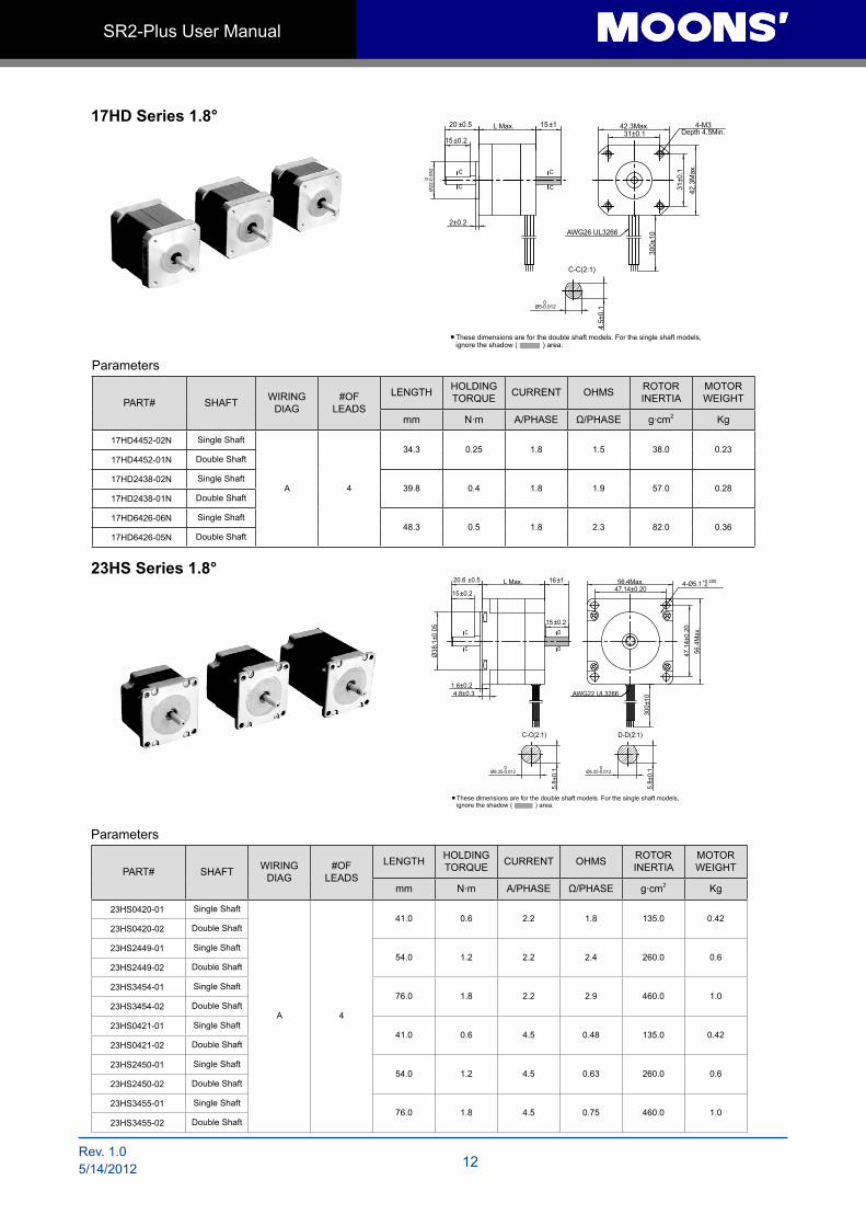
17HD Series 1.8°
Parameters
PART# SHAFT WIRINGDIAG
#OF LEADS
LENGTH HOLDINGTORQUE CURRENT OHMS ROTOR
INERTIAMOTOR WEIGHT
mm N·m A/PHASE Ω/PHASE g·cm2 Kg
17HD4452-02N Single Shaft
A 4
34.3 0.25 1.8 1.5 38.0 0.2317HD4452-01N Double Shaft
17HD2438-02N Single Shaft39.8 0.4 1.8 1.9 57.0 0.28
17HD2438-01N Double Shaft
17HD6426-06N Single Shaft48.3 0.5 1.8 2.3 82.0 0.36
17HD6426-05N Double Shaft
23HS Series 1.8°
Parameters
PART# SHAFT WIRINGDIAG
#OF LEADS
LENGTH HOLDINGTORQUE CURRENT OHMS ROTOR
INERTIAMOTOR WEIGHT
mm N·m A/PHASE Ω/PHASE g·cm2 Kg
23HS0420-01 Single Shaft
A 4
41.0 0.6 2.2 1.8 135.0 0.4223HS0420-02 Double Shaft
23HS2449-01 Single Shaft54.0 1.2 2.2 2.4 260.0 0.6
23HS2449-02 Double Shaft
23HS3454-01 Single Shaft76.0 1.8 2.2 2.9 460.0 1.0
23HS3454-02 Double Shaft
23HS0421-01 Single Shaft41.0 0.6 4.5 0.48 135.0 0.42
23HS0421-02 Double Shaft
23HS2450-01 Single Shaft54.0 1.2 4.5 0.63 260.0 0.6
23HS2450-02 Double Shaft
23HS3455-01 Single Shaft76.0 1.8 4.5 0.75 460.0 1.0
23HS3455-02 Double Shaft
C
4.5±
0.1
42.3Max.31±0.1
31±0
.1
42.3
Max
.
AWG26 UL3266
300±
10
2±0.2
20 ±0.5
15±0.2
C C
15±1L Max.
C
C-C(2:1)
4-M3Depth 4.5Min.
0Ø5-0.012
0Ø
22-0
.052
These dimensions are for the double shaft models. For the single shaft models, ignore the shadow ( ) area.
1.6±0.24.8±0.3
C
C-C(2:1) D-D(2:1)
D
5.8±
0.1
5.8±
0.1
15±0.2
20.6 ±0.5 16±1
15±0.2
L Max.
Ø38
.1±0
.05
C D
47.14±0.20
56.4
Max
.47
.14±
0.20
300±
10
AWG22 UL3266
4-Ø5.1+0.200-056.4Max.
0Ø6.35-0.012
0Ø6.35-0.012
These dimensions are for the double shaft models. For the single shaft models, ignore the shadow ( ) area.
13 Rev:1.05/14/2012
SR2-Plus User Manual
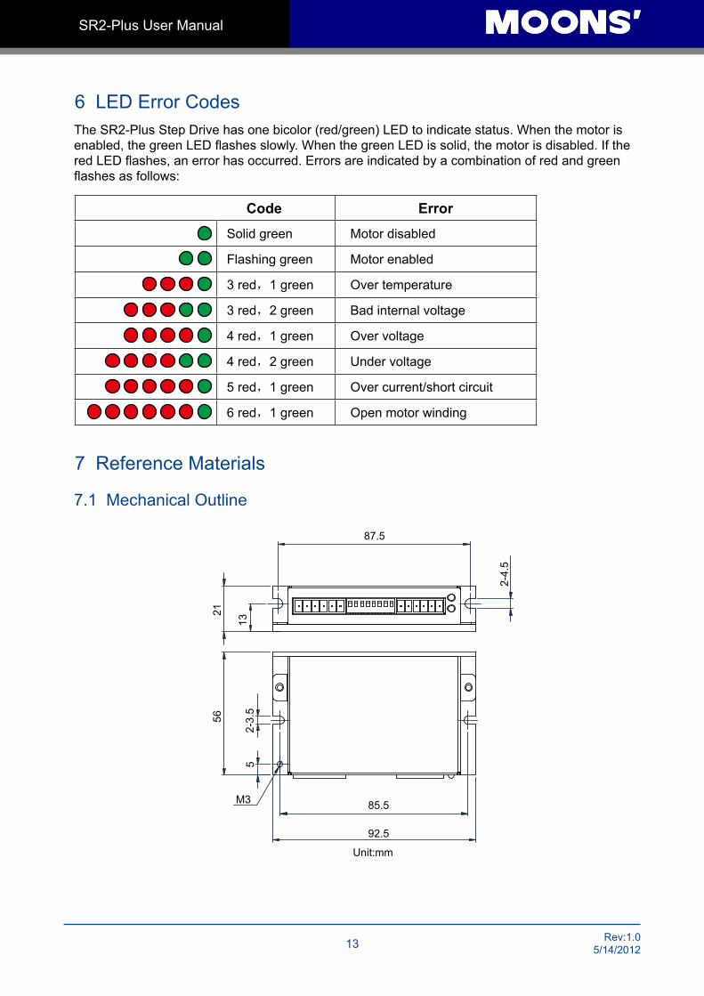
6 LED Error CodesThe SR2-Plus Step Drive has one bicolor (red/green) LED to indicate status. When the motor is enabled, the green LED flashes slowly. When the green LED is solid, the motor is disabled. If the red LED flashes, an error has occurred. Errors are indicated by a combination of red and green flashes as follows:
Code Error
Solid green Motor disabled
Flashing green Motor enabled
3 red,1 green Over temperature
3 red,2 green Bad internal voltage
4 red,1 green Over voltage
4 red,2 green Under voltage
5 red,1 green Over current/short circuit
6 red,1 green Open motor winding
7 Reference Materials
7.1 Mechanical Outline
2156
2-3.
55
13
2-4.
5
87.5
M3 85.5
92.5
Unit:mm
Rev. 1.05/14/2012 14
SR2-Plus User Manual
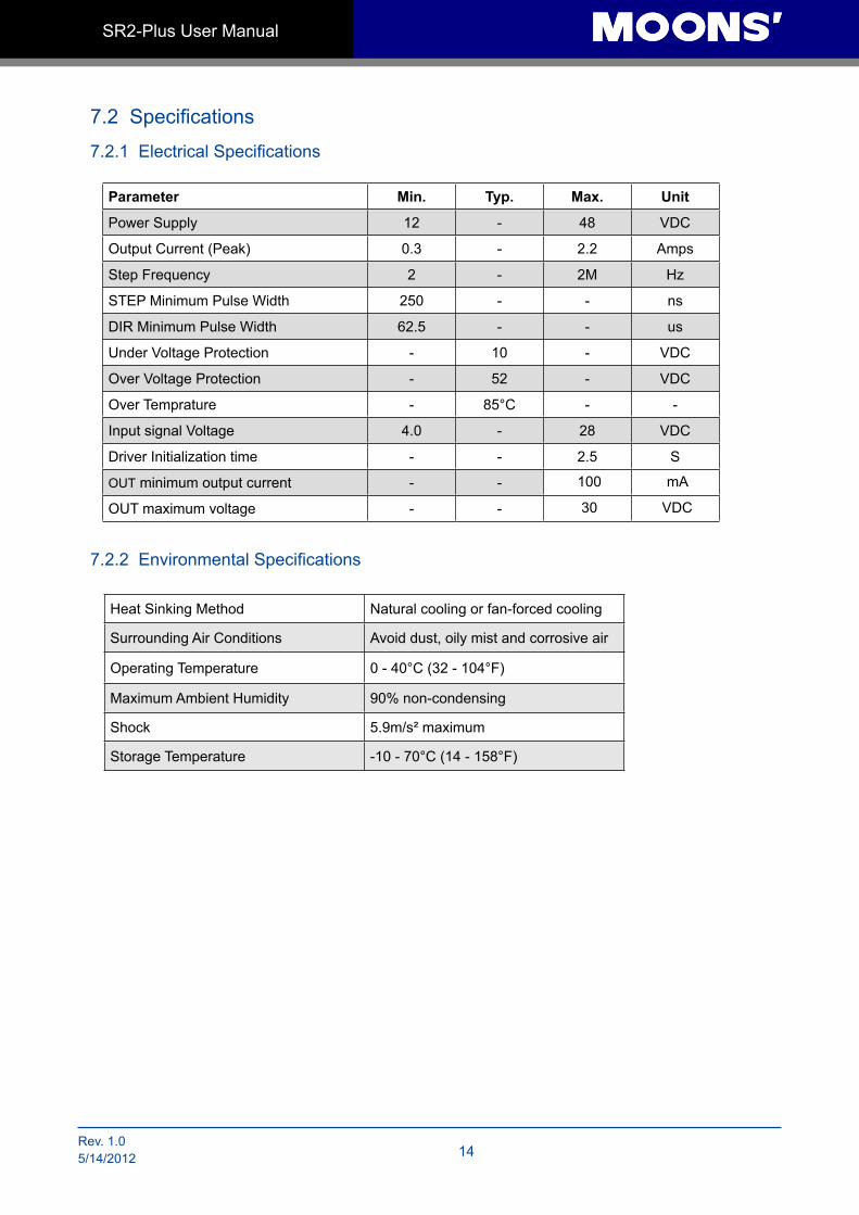
7.2 Specifications
7.2.1 Electrical Specifications
7.2.2 Environmental Specifications
Heat Sinking Method Natural cooling or fan-forced cooling
Surrounding Air Conditions Avoid dust, oily mist and corrosive air
Operating Temperature 0 - 40°C (32 - 104°F)
Maximum Ambient Humidity 90% non-condensing
Shock 5.9m/s² maximum
Storage Temperature -10 - 70°C (14 - 158°F)
Parameter Min. Typ. Max. Unit
Power Supply 12 - 48 VDC
Output Current (Peak) 0.3 - 2.2 Amps
Step Frequency 2 - 2M Hz
STEP Minimum Pulse Width 250 - - ns
DIR Minimum Pulse Width 62.5 - - us
Under Voltage Protection - 10 - VDC
Over Voltage Protection - 52 - VDC
Over Temprature - 85°C - -
Input signal Voltage 4.0 - 28 VDC
Driver Initialization time - - 2.5 S
OUT minimum output current - - 100 mA
OUT maximum voltage - - 30 VDC
15 Rev:1.05/14/2012
SR2-Plus User Manual
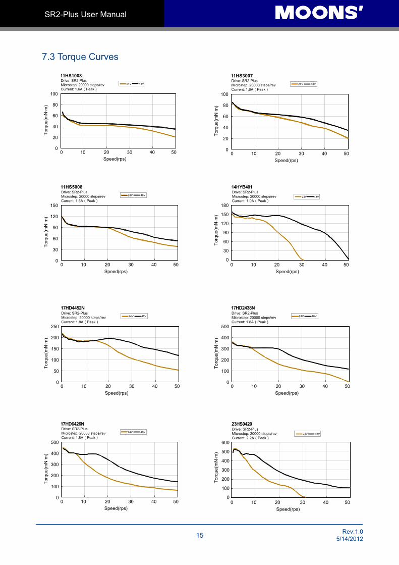
7.3 Torque Curves
11HS1008
Speed(rps)
Torq
ue(m
N m
)
100
80
60
40
20
0 0 10 20 30 40 50
.
Drive: SR2-PlusMicrostep: 20000 steps/revCurrent: 1.6A(Peak)
17HD4452N
Speed(rps)
Torq
ue(m
N m
)
250
200
150
100
50
00 10 20 30 40 50
.
Drive: SR2-PlusMicrostep: 20000 steps/revCurrent: 1.8A(Peak)
17HD2438N
Speed(rps)
Torq
ue(m
N m
)
500
400
300
200
100
00 10 20 30 40 50
.
Drive: SR2-PlusMicrostep: 20000 steps/revCurrent: 1.8A(Peak)
11HS5008
Speed(rps)
Torq
ue(m
N m
)
150
120
90
60
30
00 10 20 30 40 50
.
Drive: SR2-PlusMicrostep: 20000 steps/revCurrent: 1.6A(Peak)
11HS3007
Speed(rps)
Torq
ue(m
N m
)
100
80
60
40
20
00 10 20 30 40 50
.
Drive: SR2-PlusMicrostep: 20000 steps/revCurrent: 1.6A(Peak)
)m
Nm(euqroT
.
24V 48V
Speed(rps)
180
150
120
90
60
30
00 10 20 30 40 50
14HYB401Drive: SR2-PlusMicrostep: 20000 steps/revCurrent: 1.0A(Peak)
17HD6426N
Speed(rps)
Torq
ue(m
N m
)
500
400
300
200
100
00 10 20 30 40 50
.
Drive: SR2-PlusMicrostep: 20000 steps/revCurrent: 1.8A(Peak)
)m
Nm(euqroT
.
24V 48V
Speed(rps)
600
500
400
300
200
100
00 10 20 30 40 50
23HS0420Drive: SR2-PlusMicrostep: 20000 steps/revCurrent: 2.2A(Peak)
Rev. 1.05/14/2012 16
SR2-Plus User Manual
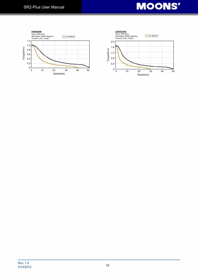
24V 48V
Speed(rps)
1.2
1.0
0.8
0.6
0.4
0.2
00 10 20 30 40 50
23HS2449
Torq
ue(N
m)
.
Drive: SR2-PlusMicrostep: 20000 steps/revCurrent: 2.2A(Peak)
23HS3454
Speed(rps)
2.0
1.6
1.2
0.8
0.4
00 10 20 30 40 50
Torq
ue(N
m)
.
Drive: SR2-PlusMicrostep: 20000 steps/revCurrent: 2.2A(Peak)
17 Rev:1.05/14/2012
SR2-Plus User Manual
8 Contacting MOONS’
HeadquartersNo. 168 Mingjia Road Industrial Park North Minhang District Shanghai 201107, P.R. China Tel: +86(0)21-52634688Fax: +86(0)21-62968682E-mail: [email protected]
MOONS' Industries (Europe) S.r.l. Via Torri Bianche n.1 20059 Vimercate(MB) ItalyTel: +39 039 62 60 521Fax: +39 039 96 31 409
MOONS' Industries (South-East Asia) Pte Ltd. 33 Ubi Avenue 3 #08-23 Vertex Singapore 408868Tel: +65 6634 1198Fax: +65 6634 1138
Shenzhen Branch OfficeRoom 2209, 22/F, Kerry Center,No. 2008 Renminnan Road Shenzhen 518001 P. R.ChinaTel: +86 (0)755 25472080Fax: +86 (0)755 25472081
Beijing Branch Office Room 202, Unit 2, 7th Building,Huilongsen International Science & Technology Industry Park, No.99, Kechuang 14th Street,Beijing 101111 P. R.ChinaTel: +86 (0)10 59755578Fax: +86 (0)10 59755579
Qingdao Branch Office Room 10E, No.73 Wangjiao Mansion, mid. Hongkong Road Qingdao 266071 P. R.ChinaTel: +86 (0)532 85879625Fax: +86 (0)532 85879512
Wuhan Branch Office Room 3001, World Trade Tower, No.686 Jiefang Avenue, Jianghan District, Wuhan 430022 P.R.ChinaTel: +86 (0)27-85448742Fax: +86 (0)27-85448355
Nanjing Branch Office Room 302, Building A, Tengfei Creation Center,55 Jiangjun Avenue, Jiangning District,Nanjing 211100 P. R.ChinaTel: +86 (0)25 52785841Fax: +86 (0)25 52785485
Chengdu Branch OfficeRoom 1917, Western Tower, No.19,4th Section of South People Road,Wuhou District,Chengdu 610041P.R.ChinaTel: +86 (0)28-85268102Fax: +86 (0)28-85268103
Service Center+86-400-820-9661