Embed Size (px)
Citation preview
SRIA’s Class L Mesh Elevated Slab Tests: Part 1A–Objectives, Design & Details
Scott Munter* and Mark Patrick**
* Steel Reinforcement Institute of Australia, PO Box 418, Roseville, New South Wales, 2069, Australia (E-mail: [email protected])
** MP Engineers Pty Limited, 6 Doowi Court, Greensborough, Victoria, 3088, Australia (E-mail: [email protected])
ABSTRACT Three series of slabs incorporating Ductility Class L mesh included specimens practically detailed and designed in accordance with AS 3600–2009. Test objectives, design and details are presented in Part 1A, and observations and results relating to ultimate strength in Part 1B. Slab test strengths are compared with design strengths in Part 2. Using a universal test rig, eight statically determinate, single-span one-way (SSOW-series) slabs with axially and rotationally unrestrained ends were tested to determine the bending strength of singly-reinforced cross-sections. Some included Class N bars acting in combination with Class L mesh as main tensile reinforcement. Four statically indeterminate slabs were also tested with fully restrained ends or edges, viz.: an SSOW-series slab; two double-span one-way (DSOW-series) slabs; and a two-way (TW-series) slab. Two statically indeterminate DSOW-series slabs with unrestrained ends were also studied. Two of the DSOW-series slabs were subjected to relative support settlement to increase ductility demand by moment redistribution, and the TW-series slab was initially proof tested to AS 3600. All of the indeterminate slabs tested had two continuous layers of Class L mesh fully anchored at their end, edge and/or interior supports, which enhanced load-carrying performance, particularly for slabs with fully restrained ends or edges due to membrane action.
KEYWORDS Low-Ductility Mesh; Membrane Action; One-Way Action; Two-Way Action; Structural Testing.
TEST OBJECTIVES AND DESIGN OF SLAB TEST SPECIMENS
Australian Research into the Behaviour of Members incorporating Class L Steel The SRIA Class L mesh slab tests were undertaken for SRIA to independently obtain detailed information about the behaviour and strength of elevated reinforced-concrete slabs incorporating Class L mesh designed in accordance with the current Concrete Structures Standard AS 3600-2009 (SA, 2009). The research project was overseen by a Peer Review Panel (PRP) comprising Australian academic and consulting structural engineering experts, who examined test procedures, witnessed critical tests and reviewed final research project documentation (Chandler and Lloyd, 2012; Curtin University and SRIA, 2011). Another role is to advise on possible future testing.
When the research project was developed early in 2007, a total of twenty-six full-scale structural tests had been reported in the literature, performed in Australia on concrete beams or one-way slabs incorporating low-ductility reinforcing steels, the earliest dating back more than a decade to before the official move to more ductile, grade 500 MPa Ductility Class L reinforcement in 2001 (Patrick and Keith, 2008). A number of shortcomings were identified with the design, scope and conduct of these tests (see explanation below), and neither had any two-way slab tests been conducted in recent times following those reported much earlier by Blakey (1963).
Design to AS 3600–2009 using Class L Mesh as Main Reinforcement Understanding the test objectives and design of the test series and specimens requires knowledge of
the rules in AS 3600–2009 for designing slabs incorporating Class L mesh as main reinforcement. Some of these rules are briefly explained below, while some are described in more detail in Part 2.
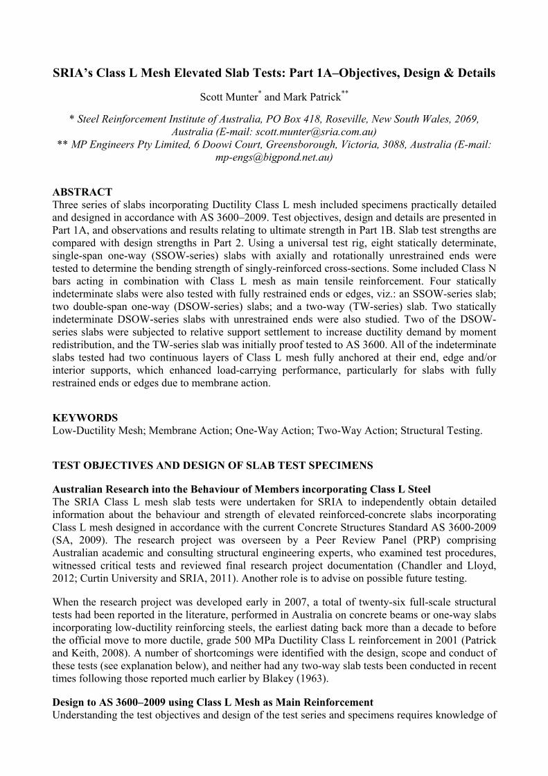
Limited Ductility of Reinforcing Steel (Clause 1.1.2 Application). In Clause 1.1.2 Application of AS 3600 it is stated that reinforcing steel of Ductility Class L "shall not be used in any situation where the reinforcement is required to undergo large plastic deformation under strength limit state conditions". Referring to the bilinear stress-strain curve in Fig. 1, in design this simply requires that Class L main bars are not assumed to be strained in tension more than the uniform strain su, which corresponds to the onset of necking. In accordance with Clause 3.2 Properties of Reinforcement of AS 3600, su has a lower characteristic value of 1.5% for Class L mesh. Steel tensile strains in excess of su ultimately result in bar fracture, with complete loss of cross-section strength local to where multiple bars fracture. In accordance with Steel Reinforcing Materials Standard AS/NZS 4671 (SA, 2001), for 500 MPa Class L bars the lower characteristic value of the tensile-to-yield-stress ratio, fsu/fsy equals 1.03, giving a corresponding design tensile strength of 515 MPa. A similar design curve to that shown in Fig. 1 for Class N bar has su =5.0% and fsu/fsy =1.08.
Figure 1. Class L mesh design tensile stress-strain curve (lower-chara. mechanical property limits).
Design for Robustness (Clause 2.1.3 Design for Robustness and Clause 9.1.3 Detailing of Tensile Reinforcement in Slabs). In accordance with Section 6 of AS/NZS 1170.0 (SA, 2002), "Structures shall be detailed such that all parts of the structure shall be tied together both in the horizontal and the vertical planes so that the structure can withstand an event without being damaged to an extent disproportionate to that event". Detailing reinforced-concrete slabs for robustness in accordance with Clause 9.1.3 Detailing of Tensile Reinforcement in Slabs of AS 3600–2009 also requires minimum specified amounts of the maximum bottom tensile reinforcement to be anchored past the inside face of edge and interior supports.
Distinction between Class N and L Reinforcement (Clause 2.2 Design for Strength) & Ductility Class of Main Reinforcement (Clause 3.2 Properties of Reinforcement). Nowhere in the Standard is there any specific mention of Class N and L reinforcing steels being used together as main reinforcement. As an example, in Table 2.2.2 Capacity Reduction Factor () the capacity reduction factor, , for bending without resultant axial tension or compression may be determined using either of the following equations as appropriate:
(i) for members with Class N reinforcement only: 0.6 (1.19 – 13kuo/12) 0.8 (1) (ii) for members with Class L reinforcement: 0.6 (1.19 – 13kuo/12) 0.64 (2)
where kuo is the neutral axis parameter (see formula under Eq. 3 below). Conservatively, Eq. 2 could be interpreted to mean that all of the main steel should be treated as Class L if Class L mesh and loose Class N bars are mixed together at a cross-section, e.g. if D500N (deformed) bars are tied to ribbed mesh, as commonly occurs. (A less conservative, alternative design approach is described in SRIA’s TN6 (SRIA, 2008).) Moreover, attempting to control widespread use of Class L reinforcing steel, Clause 3.2.1 Strength and ductility of AS 3600–2009 only addresses the use of Class L Grade 500 MPa welded-wire mesh (plain or deformed, i.e. ribbed) as main reinforcement, ignoring
0
100
200
300
400
500
600
0.0 1.0 2.0 3.0 4.0 5.0 6.0
Ten
sile
Str
ess
(MP
a)
Tensile Strain (%)
Uniform strain, su=1.5%
Tensile strength, fsu=515 MPa
Modulus ofelasticity,Es=200 GPa
Yield stress,fsy=500 MPa
Yield strain, sy=0.25%
Tensile strength reached at onsetof necking: steel fracture
assumed in design

deformed Class L Grade 500 MPa bars which in principle could be used as main reinforcement too.
Nominal moment capacity, Muo (Clause 8.1 Strength of Beams in Bending). Moment capacity calculation procedures, such as normal rectangular stress-block theory defined in Clause 8.1.3 Rectangular stress block theory, are based upon a fundamental assumption that the tensile steel has an elastic-plastic stress-strain relationship, with design yield stress fsy maintained at unlimited tensile strain, i.e. no limiting tensile strain (su) is specified to account for possible steel fracture. However, this is not an issue for singly-reinforced sections incorporating steel of only one ductility class. Therefore, nominal moment capacity, Muo, of a singly-reinforced, under-reinforced solid rectangular cross-section incorporating Class L mesh of nominal cross-sectional area, Ast, per width, b, is calculated normally as:
22 1 0.5uo c uo uoM f k k bd (3)
where 2=1.0 – 0.003 cf within the limits 0.6720.85, 20 cf 100 MPa, and =1.05 – 0.007 cf within the limits 0.670.85, and neutral axis parameter, kuo= / 0.85sy st cf A f bd 0.36. In
accordance with Clause 8.1.5 Design strength in bending, over-reinforced sections with kuo>0.36 (and M*>0.6Muo) require restrained compressive reinforcement. Further, in accordance with Clause 8.1.6 Minimum strength requirements, at critical cross-sections it is normally necessary to ensure that Muo (Muo)min (=1.2Mcr), where Mcr is the cracking moment based on the lower characteristic tensile strength of concrete, .ct ff . For rectangular, reinforced-concrete sections this is
achieved provided 2.[0.2( / ) / ]st ct f syA D d f f bd . Satisfying this requirement in regions of moment
gradient (like over interior supports) allows multiple flexural cracks to develop, which is further assisted by the strain-hardening ratio fsu/fsy exceeding unity (see Fig. 1 for example). Multiple flexural cracks in critical regions increase rotational capacity and therefore the overall deformation or ductility of reinforced-concrete flexural members.
Analysis Methods & Moment Redistribution (Section 6 Methods of Structural Analysis). All of the most commonly-used methods of analysis may be applied with Class L steel present, viz.:
(i) static analysis of determinate members or structures permitted by Clause 6.1.3 Methods of Analysis;
(ii) linear elastic analysis in accordance with Clause 6.2 Linear Elastic Analysis, but with no moment redistribution assumed to occur at the strength limit state;
(iii) finite element analysis, in accordance with Clause 6.4 Linear Elastic Stress Analysis; (iv) non-linear frame analysis accounting for non-linear geometric effects, including the effects of
compressive membrane action, in accordance with Clause 6.5 Non-Linear Frame Analysis; & (v) simplified flexural analysis in accordance with Clause 6.10 Simplified Methods of Flexural
Analysis, specifically 6.10.2 Simplified methods for reinforced continuous beams and one-way slabs or Clause 6.10.3 Simplified method for reinforced two-way slabs supported on four sides, in both cases using the rules for Class L steel designed to limit the amount of moment redistribution approaching the strength limit state, also beneficial for serviceability design.
Differential support settlement can cause additional moment redistribution, but is no longer specifically mentioned in AS 3600 as a design issue. Plastic methods of analysis defined in Clause 6.7 Plastic Methods of Analysis of AS 3600–2009, including yield-line theory, are restricted to the design of flexural members incorporating Class N main reinforcement.
Test Objectives The main technical reasons for undertaking the test program are described as follows with reference to the design rules in AS 3600–2009, and previous Australian tests involving Class L mesh.
(i) Slabs designed and detailed strictly in accordance with AS 3600–2009 – It was essential that
at least some slabs were designed and detailed strictly in accordance with all relevant aspects of AS 3600–2009. No previous test series had satisfied this criterion. The use of Class L mesh as main reinforcing steel had been questioned in the past, using narrow one-way slabs supported on rollers to exaggerate sudden failure when all the bars fractured at a single critical cross-section. While it was necessary to test some similar statically determinate slabs to these as part of the SRIA study, which do not satisfy the robustness criteria described above, they were otherwise designed in accordance with AS 3600 for serviceability and strength. All permissible methods of structural analysis were to be reviewed.
(ii) Slabs were to be representative of every-day construction – Flexural behaviour was of primary importance, with critical sections under-reinforced so that steel ductility was tested. In accordance with Table 2 of AS/NZS 4671, only Class L mesh with bar diameters, db5.0 mm satisfy Fig. 1. This is the case for square meshes SL62 and above, and rectangular meshes SL718 and above; so smaller meshes were not used. The minimum overall slab depth needed to accommodate two layers of mesh, i.e. top and bottom steel in both directions for a two-way slab, and for internal exposure conditions with minimum 20 mm cover and allowing for mesh overlaps, an overall slab depth, D=110 mm was chosen. No other Australian test series investigating the behaviour of slabs incorporating Class L mesh had modelled realistic support conditions with rigid translational and rotational restraint, and appropriate detailing of the main reinforcing steel anchorage to comply with AS 3600–2009 applicable to elevated slabs in normal buildings. Transverse shear reinforcement was excluded from all test slabs, including the two-way slab with point loads.
(iii) Typical Class L reinforcing steel was to be used – Steel with ductility properties exactly equal to or even close to the lower-characteristic values is literally impossible to source, particularly as multiple coils are normally used to manufacture each sheet of mesh. Instead, all mesh used to construct the test specimens was to be representative of normal production.
(iv) Structural strength was to be the paramount focus of the investigation – All of the slabs were to be tested to failure, including a proof test of a two-way slab in accordance with Paragraph B3 of Appendix B of AS 3600–2009, to investigate the level of safety typically associated with this common, long-standing form of construction.
(v) Potentially detrimental effects of moment redistribution were to be studied – differential support settlement was chosen as a means of imposing a large amount of moment redistribution at critical cross-sections prior to progressively vertically loading a slab through to failure. This had been performed earlier in Melbourne University tests, but the distribution of applied loads at failure was uncertain (Munter et al., 2010), limiting their value. More recently, the University of New South Wales has also tested several two-span slabs with initial support settlement (Munter et al., 2010).
(vi) Normal serviceability conditions were to be more realistically simulated – vertical deflections, steel strains and the development of flexural cracking were all recorded while simulating short-term loading events in a real structure using repeated loading. In previous studies, the slabs were only monotonically loaded in the serviceability range, and also through to failure (Patrick and Keith, 2008).
(vii) Two-way action was to be simulated for the first time – some members of the PRP and Standards Australia committee BD-002 had suggested that it would be important to test two-way slabs incorporating Class L mesh. Recently, the University of New South Wales has tested a number of two-way slabs with rotationally unrestrained edges (Sakka and Gilbert, 2008; Sakka and Gilbert, 2009). Membrane action was significant. In the SRIA study, water was to be used in the proof test in order to simulate uniformly-distributed design loads more accurately than in any previous tests.
(viii) Modelling realistic edge support conditions – it was considered very important to comply with the robustness design requirements of Australian Standards and the Building Code of Australia, including continuity of bottom tensile steel at supports, and to also allow
compressive membrane action to develop, including in one-way slabs. (ix) More accurately represent steel reinforcement mechanical properties – in particular, it was
planned to undertake much more extensive tensile testing than in any previous Australian study, to determine the variability of the mechanical properties, which are affected by the way the bars are processed and is normally different for transverse and longitudinal bars.
(x) Continuity of bottom reinforcing steel at mid-span and fixed edge supports for the first time – in no previous Australian test of a continuous one-way slab have two continuous layers of reinforcing mesh been detailed at critical sections adjacent to the interior support, i.e. doubly-reinforced cross-sections. Slabs with doubly-reinforced, built-in ends were to be tested for the first time in an Australian research project on Class L mesh reinforcement.
(xi) Mixing Class L and N reinforcing steels for the first time – cross-section bending strength was ascertained in statically-determinate slabs with their ends supported on rollers (thus not satisfying robustness design criteria), with zero to increasing numbers of Class N bars.
(xii) Vertical shear strength – the vertical shear strength of each critical section of each slab (all without any transverse shear reinforcement) was to be assessed, particularly in the continuous slabs, which support the greatest loads and therefore shear forces.
(xiii) Punching shear strength tested for the first time – the punching shear strength of a two-way slab incorporating two layers of Class L mesh but without vertical shear reinforcement was to be investigated for the first time in Australia.
Design of Slab Test Specimens A special tubular steel ringbeam (see below) was designed to repeatedly serve as a universal test rig for achieving all of the objectives described above using disposable single-span one-way (SSOW), double-span one-way (DSOW) or two-way (TW) slab test specimens supported off or attached to it. The ringbeam, made from high-strength tubular steel, was designed and detailed to resist the large torques that were predicted to develop in critical design cases with the slab edges fully built-in. Using a thick-walled RHS, the clear distances across the frame were 2140 mm and 4440 mm in the short and long directions, respectively. Designing the 110 mm deep SSOW, DSOW and TW-series slabs supporting typical design dead and live loads for both serviceability and strength in accordance with AS 3600–2009 gave rise to using SL92 and SL102 meshes, with N12 bars used to supplement the cross-sectional area of the mesh in some of the SSOW-series tests.
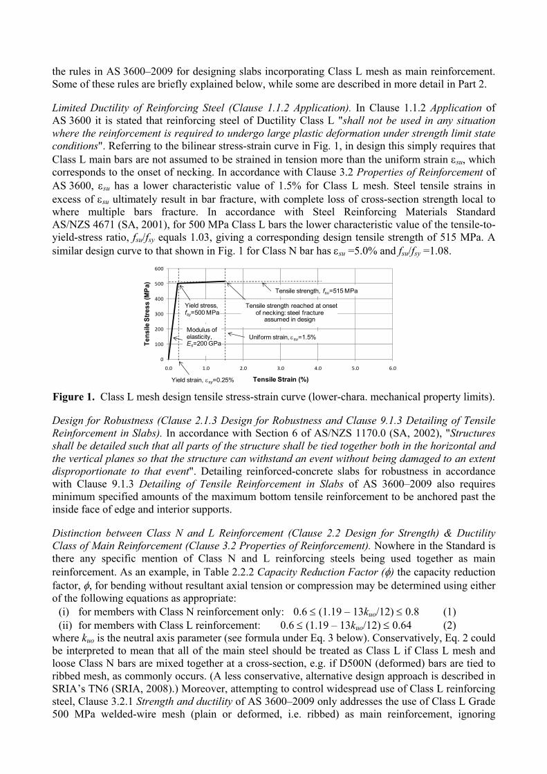
Specifically referring to Fig. 2, the graph shows the design relationship between nominal moment capacity, Muo, and neutral axis parameter, kuo, for a singly-reinforced slab cross-section of nominal overall depth D=110 mm, with cf =32 MPa and 20 mm concrete cover to the Class L tensile main
bars. Moment-curvature analysis was used to produce this relationship, using the design stress-strain curve in Fig. 1 for the steel bars of the mesh, and a standard non-linear stress-strain curve for the concrete to model softening (c>cu), and ignoring any concrete tensile stress after cracking in accordance with Clause 8.1.2 Basis of strength calculations of AS 3600–2009.
The lower limit, kuo.min, shown in Fig. 2 corresponds to Muo = (Muo)min, while to preferably avoid needing compressive reinforcement requires that kuo0.36: this explains the shaded region labelled "Preferred test specimen range". The square points in this region represent every critical section of all of the SRIA slab test specimens, conservatively treating them as singly-reinforced for the purpose of this discussion. There is significant overlap of the points due to identical nominal design situations. Many of the sections have kuo values of 0.1 or less, while the most heavily reinforced slab with the most N12 supplementary bars had a kuo value of slightly over 0.2, still well less than the upper limit of 0.36. A fault of some previous Australian Class L slab tests has been that, based on actual material properties, kuo << kuo.min due to excessively small amounts of steel being used, and higher-than-expected concrete compressive strengths, and as a result, ultimate failure occurred with only a single flexural crack forming, and therefore overall ductility was unrealistically low.
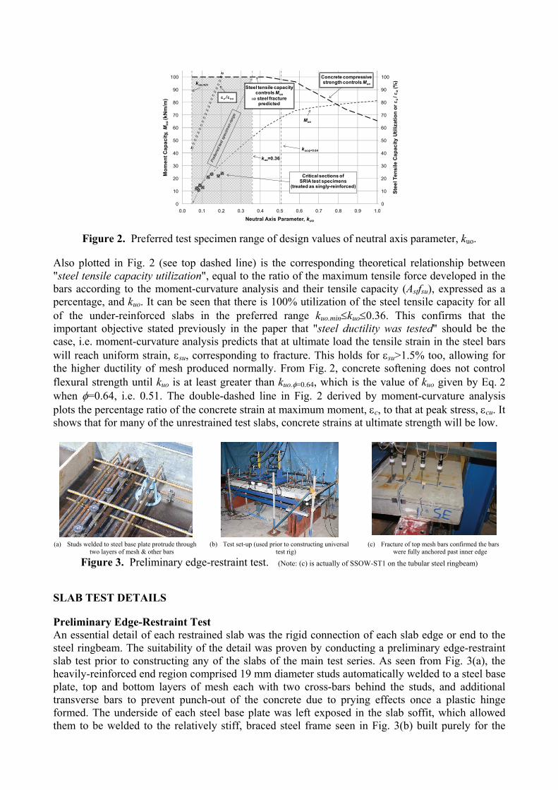
Figure 2. Preferred test specimen range of design values of neutral axis parameter, kuo.
Also plotted in Fig. 2 (see top dashed line) is the corresponding theoretical relationship between "steel tensile capacity utilization", equal to the ratio of the maximum tensile force developed in the bars according to the moment-curvature analysis and their tensile capacity (Astfsu), expressed as a percentage, and kuo. It can be seen that there is 100% utilization of the steel tensile capacity for all of the under-reinforced slabs in the preferred range kuo.minkuo0.36. This confirms that the important objective stated previously in the paper that "steel ductility was tested" should be the case, i.e. moment-curvature analysis predicts that at ultimate load the tensile strain in the steel bars will reach uniform strain, su, corresponding to fracture. This holds for su>1.5% too, allowing for the higher ductility of mesh produced normally. From Fig. 2, concrete softening does not control flexural strength until kuo is at least greater than kuo.=0.64, which is the value of kuo given by Eq. 2 when =0.64, i.e. 0.51. The double-dashed line in Fig. 2 derived by moment-curvature analysis plots the percentage ratio of the concrete strain at maximum moment, c, to that at peak stress, cu. It shows that for many of the unrestrained test slabs, concrete strains at ultimate strength will be low.
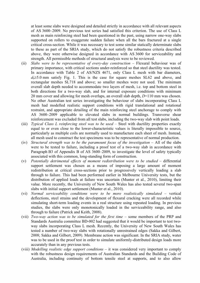
(a) Studs welded to steel base plate protrude through
two layers of mesh & other bars (b) Test set-up (used prior to constructing universal
test rig) (c) Fracture of top mesh bars confirmed the bars
were fully anchored past inner edge
Figure 3. Preliminary edge-restraint test. (Note: (c) is actually of SSOW-ST1 on the tubular steel ringbeam)
SLAB TEST DETAILS
Preliminary Edge-Restraint Test An essential detail of each restrained slab was the rigid connection of each slab edge or end to the steel ringbeam. The suitability of the detail was proven by conducting a preliminary edge-restraint slab test prior to constructing any of the slabs of the main test series. As seen from Fig. 3(a), the heavily-reinforced end region comprised 19 mm diameter studs automatically welded to a steel base plate, top and bottom layers of mesh each with two cross-bars behind the studs, and additional transverse bars to prevent punch-out of the concrete due to prying effects once a plastic hinge formed. The underside of each steel base plate was left exposed in the slab soffit, which allowed them to be welded to the relatively stiff, braced steel frame seen in Fig. 3(b) built purely for the
0
10
20
30
40
50
60
70
80
90
100
0
10
20
30
40
50
60
70
80
90
100
0.0 0.1 0.2 0.3 0.4 0.5 0.6 0.7 0.8 0.9 1.0
Ste
el T
en
sil
e C
ap
ac
ity
Uti
liza
tio
n o
r c
/ u
(%)
Mo
me
nt
Ca
pa
cit
y, M
uo
(kN
m/m
)
Neutral Axis Parameter, kuo
kuo.min
Muo
kuo=0.36
kuo.=0.64
Critical sections ofSRIA test specimens
(treated as singly-reinforced)
Concrete compressivestrength controls Muo
Steel tensile capacitycontrols Muo
steel fracturepredicted
c / cu
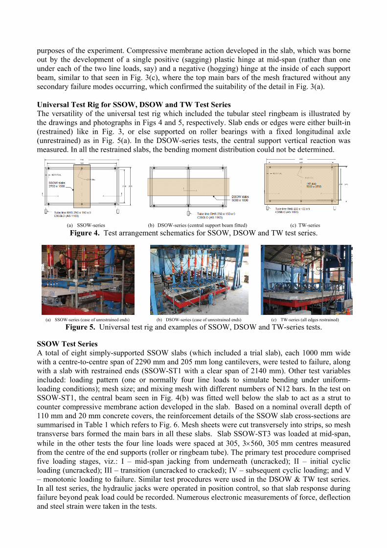
purposes of the experiment. Compressive membrane action developed in the slab, which was borne out by the development of a single positive (sagging) plastic hinge at mid-span (rather than one under each of the two line loads, say) and a negative (hogging) hinge at the inside of each support beam, similar to that seen in Fig. 3(c), where the top main bars of the mesh fractured without any secondary failure modes occurring, which confirmed the suitability of the detail in Fig. 3(a).
Universal Test Rig for SSOW, DSOW and TW Test Series The versatility of the universal test rig which included the tubular steel ringbeam is illustrated by the drawings and photographs in Figs 4 and 5, respectively. Slab ends or edges were either built-in (restrained) like in Fig. 3, or else supported on roller bearings with a fixed longitudinal axle (unrestrained) as in Fig. 5(a). In the DSOW-series tests, the central support vertical reaction was measured. In all the restrained slabs, the bending moment distribution could not be determined.
(a) SSOW-series (b) DSOW-series (central support beam fitted) (c) TW-series
Figure 4. Test arrangement schematics for SSOW, DSOW and TW test series.
(a) SSOW-series (case of unrestrained ends) (b) DSOW-series (case of unrestrained ends) (c) TW-series (all edges restrained)
Figure 5. Universal test rig and examples of SSOW, DSOW and TW-series tests.
SSOW Test Series A total of eight simply-supported SSOW slabs (which included a trial slab), each 1000 mm wide with a centre-to-centre span of 2290 mm and 205 mm long cantilevers, were tested to failure, along with a slab with restrained ends (SSOW-ST1 with a clear span of 2140 mm). Other test variables included: loading pattern (one or normally four line loads to simulate bending under uniform-loading conditions); mesh size; and mixing mesh with different numbers of N12 bars. In the test on SSOW-ST1, the central beam seen in Fig. 4(b) was fitted well below the slab to act as a strut to counter compressive membrane action developed in the slab. Based on a nominal overall depth of 110 mm and 20 mm concrete covers, the reinforcement details of the SSOW slab cross-sections are summarised in Table 1 which refers to Fig. 6. Mesh sheets were cut transversely into strips, so mesh transverse bars formed the main bars in all these slabs. Slab SSOW-ST3 was loaded at mid-span, while in the other tests the four line loads were spaced at 305, 3560, 305 mm centres measured from the centre of the end supports (roller or ringbeam tube). The primary test procedure comprised five loading stages, viz.: I – mid-span jacking from underneath (uncracked); II – initial cyclic loading (uncracked); III – transition (uncracked to cracked); IV – subsequent cyclic loading; and V – monotonic loading to failure. Similar test procedures were used in the DSOW & TW test series. In all test series, the hydraulic jacks were operated in position control, so that slab response during failure beyond peak load could be recorded. Numerous electronic measurements of force, deflection and steel strain were taken in the tests.
Table 1. Reinforcement details of SSOW, DSOW and TW test series slab cross-sections.
Test Series
Test Spec. No.
1000 mm wide slab strip – Units in millimetres for length, or mm2 for area
Bending: +ve Bending: -ve
Mesh b.L.cd
Ls
st.LA Ld
Ns st.NA
Nd Mesh
b.L.cd
Ls
st.LA Ld
Ns
st.NA
Nd
SSOW SSOW–ST1 SL102 9.5 200 354 85.3 - - - SL92 8.6 200 290 85.7 - - -
SSOW–ST2 SL92 8.6 200 290 85.7 - - - - - - - - - - - SSOW–ST3 SL92 8.6 200 290 85.7 - - - - - - - - - - - SSOW–ST4 SL102 9.5 200 354 85.3 - - - - - - - - - - - SSOW–ST5 SL102 9.5 200 354 85.3 500 226 86.5 - - - - - - - - SSOW–ST6 SL102 9.5 200 354 85.3 333 339 65.0 - - - - - - - - SSOW–ST7 SL92 8.6 200 290 85.7 500 226 87.4 - - - - - - - - SSOW–ST8 SL92 8.6 200 290 85.7 333 339 66.8 - - - - - - - -
SSOW–TRIAL
SL102 9.5 200 354 85.3 - - - - - - - - - - -
DSOW DSOW–ST1 SL92 8.6 200 290 85.7 - - - SL102 9.5 200 354 85.3 - - - DSOW–ST2 SL92 8.6 200 290 85.7 - - - SL102 9.5 200 354 85.3 - - - DSOW–ST3 SL92 8.6 200 290 85.7 - - - SL102 9.5 200 354 85.3 - - - DSOW–ST4 SL92 8.6 200 290 85.7 - - - SL102 9.5 200 354 85.3 - - -
TW TW-ST1 (Short)
SL102 9.5 200 354 85.3 - - - SL92 8.6 200 290 85.7 - - -
TW-ST1 (Long)
SL102 9.5 200 354 75.8 - - - SL92 8.6 200 290 77.1 - - -
(a) Positive bending (top steel, if any, omitted for clarity) (b) Negative bending (bottom steel always present)
Figure 6. Typical transverse cross-sections of SSOW, DSOW and TW series slabs.
DSOW Test Series The reinforcement details of the four nominally-identical DSOW slabs are summarised in Table 1 too. Sheets of mesh were cut longitudinally into strips, so mesh longitudinal bars formed the main bars in all the DSOW-series slabs. Slabs DSOW-ST1 and ST2 were restrained, and slabs DSOW-ST3 and ST4 were unrestrained. Only one of each of these pairs of slabs (DSOW-ST2 or DSOW-ST4) was subjected to relative support settlement (5 mm up at the centre support), so that its effects could be observed directly. Each slab was 1000 mm wide with two equal centre-to-centre spans of 2295 mm and 205 mm long cantilevers. The centre support comprised a 150 mm wide, rotationally-restrained steel plate supported on load cells, but the slabs were not connected to this plate. The four line loads in each span were spaced at 300, 3565, 300 mm centres measured from the centre of the end supports (roller or nominal 150 mm wide ringbeam tube), and both spans were loaded equally.
TW Test Series A two-way slab with restrained edges was tested with the central support beam in Fig. 4(b) absent, so the clear spans were 2140 and 4440 mm in the short and long directions, respectively. All cross-sections were doubly-reinforced according to Table 1. Water retained by a pool liner was initially used to uniformly load the slab as part of a proof-load test conducted in accordance with AS 3600–2009, firstly for serviceability (10.0 kPa) and then factored ultimate load (15.5 kPa) conditions. Next the slab was tested to failure using four hydraulic jacks, which each applied an equal vertical point load distributed over a 200200 mm patch area comprising a bedded steel plate symmetrically positioned about the slab centre: 300 and 900 mm each side of the short and long span centrelines, respectively. As in all three test series, the ringbeam was supported on load cells, three along each long side, which together measured the combined force due to self-weight and the applied load.
CONTINUED IN PART 1B.
st.LA
st.NA
Ld
Nd
Ls
Ns
D
c
b.Ld
b.Nd
st.LA
LdLs
D
c
b.Ld
c


![Disaster Resistant Designs 2013-08-12DJB [Read-Only]media.iccsafe.org/news/annual_conference/2013-AtlanticCity/... · “Voided” Elevated Slab • “Two-way reinforcement • Carries](https://img.pdfslide.net/doc/110x75/5aab8f2e7f8b9a693f8c107e/disaster-resistant-designs-2013-08-12djb-read-onlymedia-voided-elevated.jpg)