Embed Size (px)
Citation preview

GRUNDFOS DATA BOOKLET
Submersible recirculation pumpsSRP50 Hz

Ta
ble
of c
on
ten
ts
2
Submersible recirculation pumps
1. Introduction 3General description 3Applications 3Constructional features 3Operating mode 3
2. Identification 4Type key 4Nameplate 5
3. Product description 6Features 6Wiring diagrams 7Water-in-oil sensor 7Pumped liquids 8Sound pressure 8Motor range 8Explosion-proof variants 8
4. Selection of product 9Ordering a recirculation pump 9Selecting an SRP pump 9Selection curve charts, 50 Hz 13
5. Product range 18Standard versions, 400 V 50 Hz 18Standard versions, 415 V 50 Hz 18Explosion-proof versions, 400 V 50 Hz 19
6. Variants 20Variants 20
7. Construction 21Pump 21Installation drawing 21Material specification 22Sectional drawings 23Dimensions, accessories 29
8. Positioning 30General description 30
9. Technical data, 400 V, 50 Hz 31SRP.08.30.526.08.(Ex) 31SRP.10.30.606.08(.Ex) 32SRP.13.30.678.08(.Ex) 33SRP.16.30.745.08(.Ex) 34SRP.18.30.806.08(.Ex) 35SRP.30.30.517.25(.Ex) 36SRP.40.30.593.25 37SRP.50.30.684.25 38SRP.60.30.752.25(.Ex) 39SRP.70.30.814.25(.Ex) 40SRP.35.50.257.27(.Ex) 41SRP.50.50.291.27(.Ex) 42SRP.65.50.343.27(.Ex) 43SRP.80.50.378.27(.Ex) 44SRP.100.50.412.27 45SRP.70.80.263.11(.Ex) 46SRP.100.80.303.11 47SRP.120.80.323.11(.Ex) 48SRP.130.80.340.11(.Ex) 49SRP.160.80.355.11(.Ex) 50SRP.130.80.375.11(.Ex) 51SRP.200.80.388.11(.Ex) 52
SRP.180.80.387.11(.Ex) 53SRP.240.80.417.11 54SRP.180.80.417.11(.Ex) 55
10. Technical data, 415 V, 50 Hz 56SRP.08.30.526.08 56SRP.10.30.606.08 57SRP.13.30.678.08 58SRP.16.30.745.08 59SRP.18.30.517.25 60SRP.30.30.517.25 61SRP.40.30.593.25 62SRP.50.30.684.25 63SRP.60.30.752.25 64SRP.70.30.814.25 65SRP.35.50.257.27 66SRP.50.50.291.27 67SRP.65.50.343.27 68SRP.80.50.378.27 69SRP.100.50.412.27 70SRP.70.80.263.11 71SRP.100.80.303.11 72SRP.120.80.323.11 73SRP.130.80.340.11 74SRP.160.80.355.11 75SRP.130.80.375.11 76SRP.200.80.388.11 77SRP.180.80.387.11 78SRP.240.80.417.11 79SRP.180.80.417.11 80
11. Accessories 81Selection guide for accessories 82List of accessories 82
12. Further product information 85WebCAPS 85WinCAPS 86GO CAPS 87

Intr
od
uc
tio
n
Submersible recirculation pumps 1
1. Introduction
General descriptionThis data booklet describes Grundfos submersible recirculation pumps, type SRP.
Fig. 1 SRP
The Grundfos submersible recirculation pumps are designed for the transfer of liquids of low to medium viscosity.
The pumps are for DN 300, DN 500 and DN 800 pipe diameters and have motors of 0.8 to 24 kW.
The pumps incorporate a squirrel-case induction motor, a planetary gear and a cast stainless-steel impeller ensuring high resistance to wear and corrosion. The 3-dimensional optimised hydraulic design ensures high efficiency.
ApplicationsGrundfos SRP recirculation pumps are designed for the pumping of sludge from one tank to another in sewage treatment plants and for other pump applications involving a high flow rate and low head.
Constructional features• Strong axial gear in slim design for high hydro-
dynamic efficiency
• integrated overload and overheating protection
• integrated leak sensor
• cast stainless-steel impeller
• good self-cleaning capabilities.
Operating mode• Continuous operation when fully submerged
• intermittent operation with max. 20 starts per hour.
Gr9
42
2
3

Ide
ntific
atio
n
4
Submersible recirculation pumps2
2. Identification
Type key
Code Example SRP 70 30. 814. 25. Ex 5. 1A. A
SRPType rangeSubmersible recirculation pump
70
Motor output power, P2Code from type designation/10 [kW]7.0 kW
30Impeller diameter 30 cm
814Impeller speed814
25Blade pitch 25 degrees
[ ]Ex
Explosion protectionNon-explosion-proofExplosion-proof
56
Frequency50 Hz60 Hz
0A1A0B1B0V1V0Z1Z
Supply voltage and starting method400 V, DOL400 V, Y/D400-415 V, DOL400-415 V, Y/D415 V, DOL415 V, Y/DSpecial, DOLSpecial, Y/D
[ ]AB
GenerationFirst generationSecond generationThird generation

Ide
nti
fic
ati
on
Submersible recirculation pumps 2
NameplateThe nameplate is fitted to the motor housing. The details supplied on the nameplate are required for ordering spare parts.
Fig. 2 Nameplate, standard version
Key to nameplate
For reference purposes, the additional nameplate supplied with the recirculation pump should be fixed in a visible position at the installation site.
Fig. 3 Nameplate, explosion-proof version
Key to nameplateT
M0
3 0
31
5 3
31
0
Pos. Description
1 Type designation
2 Production code
3 Impeller diameter
4 Liquid temperature range
5 Product number
6 Enclosure class according to IEC
7 Serial number
8 Insulation class
9 Rated voltage
10 Rated speed (impeller)
11 Weight
12 Starting current
13 Frequency
14 Number of poles
15 Rated current
16 Power factor
17 Motor power, P1/P2
18 Model
19 Maximum installation depth
TypeP.c.
P1/P2
Cos.
Model
mm
AHz°c
ø
IN nN
PolT
Prod.No:
96257011
See MANUAL!CH-6105 Schachen
Insul.class:No:IPU VIstart
Weight kg/minA
15 1214 13
1 2 3 4 5 6 7
18
17
16
19
kW
m9
10
11
8
TM
04
90
93
33
10
Pos. Description
1 Type designation
2 Production code
3 Impeller diameter
4 Liquid temperature range
5 Product number
6 Enclosure class according to IEC
7 Serial number
8 Insulation class
9 Rated voltage
10 Rated speed (impeller)
11 Weight
12 Nominal response temperature (NRT)
13 Starting current
14 Frequency
15 Number of poles
16 Rated current
17 ATEX category
18 ATEX approval class
19 Power factor
20 Motor power, P1/P2
21 Model
22 Maximum installation depth
TypeP.c.
ModelP1/P2
Cos.Ex
1258 II 2G
kW
CH-6105 Schachen
SEV 06ATEX 0110 X 96257016
PolTø mm
°CHzA
Prod. No.No.
See MANUAL!
IP Insul. class:
IStart
WeightA nNIN
V/min
kgNAT130°C
89
10
11
1 2 3 4 5 6 7
121314151617
2221201918
5
Pro
du
ct d
es
crip
tion
6
Submersible recirculation pumps3
3. Product description
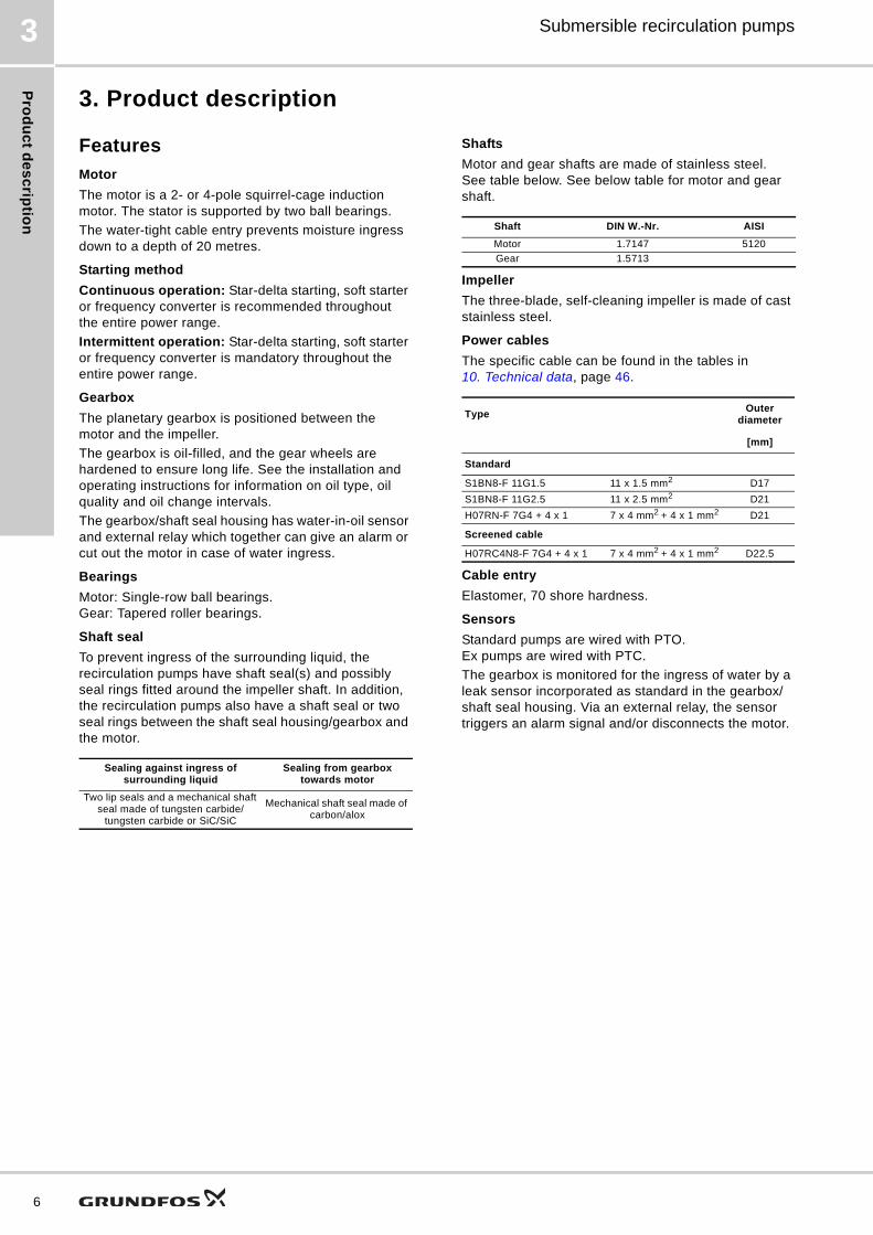
Features
Motor
The motor is a 2- or 4-pole squirrel-cage induction motor. The stator is supported by two ball bearings.
The water-tight cable entry prevents moisture ingress down to a depth of 20 metres.
Starting method
Continuous operation: Star-delta starting, soft starter or frequency converter is recommended throughout the entire power range.
Intermittent operation: Star-delta starting, soft starter or frequency converter is mandatory throughout the entire power range.
Gearbox
The planetary gearbox is positioned between the motor and the impeller.
The gearbox is oil-filled, and the gear wheels are hardened to ensure long life. See the installation and operating instructions for information on oil type, oil quality and oil change intervals.
The gearbox/shaft seal housing has water-in-oil sensor and external relay which together can give an alarm or cut out the motor in case of water ingress.
Bearings
Motor: Single-row ball bearings.Gear: Tapered roller bearings.
Shaft seal
To prevent ingress of the surrounding liquid, the recirculation pumps have shaft seal(s) and possibly seal rings fitted around the impeller shaft. In addition, the recirculation pumps also have a shaft seal or two seal rings between the shaft seal housing/gearbox and the motor.
Shafts
Motor and gear shafts are made of stainless steel. See table below. See below table for motor and gear shaft.
Impeller
The three-blade, self-cleaning impeller is made of cast stainless steel.
Power cables
The specific cable can be found in the tables in 10. Technical data, page 46.
Cable entry
Elastomer, 70 shore hardness.
Sensors
Standard pumps are wired with PTO. Ex pumps are wired with PTC.
The gearbox is monitored for the ingress of water by a leak sensor incorporated as standard in the gearbox/shaft seal housing. Via an external relay, the sensor triggers an alarm signal and/or disconnects the motor.
Sealing against ingress of surrounding liquid
Sealing from gearbox towards motor
Two lip seals and a mechanical shaft seal made of tungsten carbide/
tungsten carbide or SiC/SiC
Mechanical shaft seal made of carbon/alox
Shaft DIN W.-Nr. AISI
Motor 1.7147 5120
Gear 1.5713
TypeOuter
diameter
[mm]
Standard
S1BN8-F 11G1.5 11 x 1.5 mm2 D17
S1BN8-F 11G2.5 11 x 2.5 mm2 D21
H07RN-F 7G4 + 4 x 1 7 x 4 mm2 + 4 x 1 mm2 D21
Screened cable
H07RC4N8-F 7G4 + 4 x 1 7 x 4 mm2 + 4 x 1 mm2 D22.5

Pro
du
ct
de
sc
rip
tio
n
Submersible recirculation pumps 3
Wiring diagrams
Wiring diagram, three thermal switches (PTO)
Fig. 4 Wiring diagram, three thermal switches
Wiring diagram, three thermistors (PTC)
Fig. 5 Wiring diagram, three thermistors
Water-in-oil sensorThe gearbox is monitored for the ingress of water by a water-in-oil sensor incorporated as standard in the gearbox/shaft seal housing. Via an external relay, the sensor triggers an alarm signal and/or switches off the motor.
We recommend to connect the sensor to a relay. The relay used must be a Grundfos ALR-20/A-Ex type relay, supplied as an optional accessory. See 11. Accessories, page 81.
Note: Being an electronic component, the water-in-oil sensor must not be tested with an ohmmeter or other measuring instrument.
ALR-20/A relay
Fig. 6 ALR-20/A relay
Dimensional sketch, ALR-20/A relay
Fig. 7 Dimensions of ALR-20/A relay
TM
02
49
40
33
08
Terminals Description
1, 2, 3, 4, 5, 6Ends of the three stator windings (U1, U2, V1, V2, W1, W2)
11, 12 Thermal switches (F6)
21, 22 Leak sensor in gearbox (B) (water-in-oil sensor)
TM
02
49
32
33
08
Terminals Description
1, 2, 3, 4, 5, 6Ends of the three stator windings (U1, U2, V1, V2, W1, W2)
31, 32 Thermistors (according to DIN 44 081) (J1, J2, J3)
21, 22 Leak sensor in gearbox (water-in-oil sensor)
B
LSV2U2W2W1V1U1 PEPTO
LSV2U2V1U1 W2W1 PTC PE
TM
03
20
60
35
05
TM
02
88
67
09
04
2 10 4 1 3A1 A2
arnold agLecksonden RelaisNetz 230V 50-60Hz P3VA
II (2)G [EEx ib] IIC nur für den Anschluss von Arnold AGLecksonden Typ AL05 Ex
Schaltpunkt Storung
ALR 20/A ExSEV 05 ATEX 0131
12585 7Sonde
Rel.Netz
CH - 6105 SchachenA Grundfos Company
ab
ALR 20/A
48
35
42.5
96
485 7
Netz 230V 40-60Hz P3VARel. Ue 400V le 2.5A AC15
2 10 4 1 3A1 A2
NetzRel.
7

Pro
du
ct d
es
crip
tion
8
Submersible recirculation pumps3
Settings
The sensitivity of the ALR-20/A-Ex relay can be tested as follows:
1. Turn the adjusting screw a until the indicator light b of the relay is on. See fig. 6.
2. Turn the adjusting screw in the opposite direction until the indicator light is off.
3. Turn the adjusting screw another 60 ° (in the same direction as under step 2).
Note: The maximum cable length between the relay and the mixer/flowmaker is 50 metres. An external alarm indicator, if any, must be connected to the potential-free output, terminals 1 and 3 or 4.
For further information, see the data sheet for ALR 20/A Ex.
Pumped liquids
Sound pressureThe sound pressure level of the pump is lower than 70 dB (A)
Motor range
50 Hz
Explosion-proof variantsUse explosion-proof pumps in potentially explosive environments. The explosion classification is II 2G Ex e ck ib IIC T3
In each individual case, the installation must be approved by the local authorities.
Main supply, terminals 2 and 10
Rated operating voltage : 230 V AC
Permissible voltage tolerance : - 15 % to + 10 %
Frequency : 50-60 Hz
Power input : approx. 3 VA
Power transformer :According to VDE 0551, VDE and SEV mark of conformity.
Relay output, terminals 4, 1 and 3
Max. switching voltage : 250 VAC/24 V DC
Max. switching current : 5 A
Max. switching capacity : 100 VA/100 W
pH value : 4-10
Liquid temperature : 5 to +40 °C
Maximum density : 1060 kg/m3
Maximum dynamic viscosity : 500 mPas
Maximum sludge index : 125 ml/g
Chloride content : 200 mg/l(for stainless steel DIN W.-Nr. 1.4301)
Pump type Shaft power [kW]Number of
poles
SRP.08.30.526.08. 0.8
2
SRP.10.30.606.08. 1.0
SRP.13.30.678.08. 1.3
SRP.16.30.745.08. 1.6
SRP.18.30.806.08. 1.8
SRP.30.30.517.25. 3.0
SRP.40.30.593.25. 4.0
SRP.50.30.684.25. 5.0
SRP.60.30.752.25. 6.0
SRP.70.30.814.25. 7.0
SRP.35.50.257.27. 3.5
4
SRP.50.50.291.27. 5.0
SRP.65.50.343.27. 6.5
SRP.80.50.378.27. 8.0
SRP.100.50.412.27. 10.0
SRP.70.80.263.11. 7.0
SRP.100.80.303.11. 10.0
SRP.120.80.323.11. 12.0
SRP.130.80.340.11. 13.0
SRP.160.80.355.11. 16.0
SRP.130.80.375.11. 13.0
SRP.200.80.388.11. 20.0
SRP.180.80.387.11. 18.0
SRP.240.80.417.11. 24.0
SRP.180.80.417.11. 18.0

Se
lec
tio
n o
f p
rod
uc
t
Submersible recirculation pumps 4
4. Selection of product
Ordering a recirculation pumpFew product numbers need to be selected to make the order complete:
• SRP recirculation pump (standard)
• custom-built variants (option)
• mechanical installation accessories
• electrical accessories, leak detector relay and variable speed drive.
Standard pumpSee below example of what you get when you order a standard SRP pump:
• Recirculation pump
• 10 m cable
• paint, graphic grey, NCS8005-r-80b 350 m thickness
• three thermal switches (PTO), one in each motor winding
• or three thermal sensors (PTC), one in each motor winding for explosion-proof versions only
• one water-in-oil sensor incorporated in the gearbox.
Note: In WebCAPS you can find product specific data via the product number, e.g. 96569932.
VariantsIf a longer cable or an explosion-proof version is required, it is no longer a standard pump. A list of variants can be found in Variants, page 20.
AccessoriesFor selection of the correct accessories, see 11. Accessories, page 81.
Note: The accessories are not fitted from factory.
ControllerControl unit ALR-20/A Ex can be used in combination with SRP pumps.
Selecting an SRP pumpThe selection guide is for guidance only. For detailed information, please contact Arnold AG - A Grundfos Company, Switzerland. The selection curve charts for the Grundfos SRP pumps shown later in this section are based on the following:
• system description and layout
• flow rate, Q, in l/sec
• geometrical head, Hgeo, in m (Hgeo = H2 - H1).
Fig. 8 System layout
Head loss can be calculated on the basis of information in the system layout.
SymbolsThese symbols are used in the calculations on the following pages:
Equations
Cross-sectional area of pipes
SRP Product number
SRP.30.30.517.25 96569932
TM
03
05
71
34
08
A = Area
D = Internal pipe diameter
L = Length of pipe
g = Acceleration of gravity (9.81 m/sec2)
H = Total pump head
H1 = Liquid level in tank 1
H2 = Liquid level in tank 2
Hf = Head loss due to friction
Hgeo = Geodetic head
Hsystem = Head loss in system
HJ = Head loss in pipes
HJn = Head loss in fittings and system
Hvalve = Head loss in valves (supplier data - typically 0.05 to 0.5 m)
Q = Flow rate
V = Flow velocity
= Loss coefficient
Hf = Hgeo + Hsystem
Hsystem = Hvalve +HJn + HJ
DN Area [m2]
300 0.0707
400 0.1257
500 0.1963
600 0.2827
700 0.3848
800 0.5027
D
L
H2
H1
V = Q [m3/sec]
A [m2]
9

Se
lec
tion
of p
rod
uc
t
10
Submersible recirculation pumps4
Pipe loss nomogram
Fig. 9 Pipe loss nomogram
TM
03
05
85
03
05
Gu
ide
va
lue
s f
or
su
rfa
ce
ro
ug
hn
es
s (
k)
for
pip
es
Pip
e m
ate
ria
lN
ew
pip
e
k [
mm
]O
ld p
ipe
k
[mm
]
Pla
stic
0.0
10
.25
Dra
wn
ste
el
0.0
51
.0
We
lde
d s
tee
l0
.11
.0
Dra
wn
sta
inle
ss s
tee
l0
.05
0.2
5
We
lde
d s
tain
less
ste
el
0.1
0.2
5
Ca
st ir
on
0.2
51
.0
Ga
lva
nis
ed
ste
el
0.1
5
Bitu
min
ise
d c
ast
iro
n0
.12
Co
ncr
ete
0.3
...2
.0
Asb
est
os
cem
en
t0
.02
5
Pip
e lo
ss n
om
og
ram
fo
r cl
ea
n w
ate
r, 2
0 °
C
Q =
Flo
w [
l/s]
D =
In
tern
al p
ipe
dia
me
ter
[mm
]k
= S
urf
ace
ro
ug
hn
ess
[m
m]
HJ
= P
ipe
loss
es
[m/1
00
m]
Exa
mp
le:
Q =
12
l/s
D =
10
0 m
mk
= 0
.1 m
mH
J =
2.5
m/1
00
m

Se
lec
tio
n o
f p
rod
uc
t
Submersible recirculation pumps 4
Head loss in fittings and systems
Fig. 10 Head loss in elbow
Fig. 11 Head loss in expansion
Fig. 12 Head loss in reduction
Fig. 13 Head loss in outlet
TM
03
08
37
05
05
R/D 1 2 3 4 6
z 0.36 0.19 0.16 0.15 0.21
R/D 8 10 12 16 20
z 0.28 0.32 0.35 0.39 0.41T
M0
3 0
83
8 0
50
5
b° 5 10 15 20 30 40 45 50
k 0.13 0.17 0.26 0.41 0.71 0.90 0.93 1.05
° 60 70 80 90 100 120 140 160
k 1.12 1.13 1.10 1.07 1.06 1.05 1.04 1.02
D
R
90º
V1
A1
A2
V2
HJn V12g-------
2= k 1
A1A2-------–
2
=
TM
03
08
39
05
05
TM
03
08
40
05
05
HJn 0
V2<<V1
V1
HJn
V12
2g-------=
11

Se
lec
tion
of p
rod
uc
t
12
Submersible recirculation pumps4
ExampleCalculation of H [m]
Q = 325 l/sec
H = 0.49 m
On the basis of the above calculation, we can now determine that SRP.35.50.257.27.(Ex).5.1A.A is suitable for the application.
Fig. 14 Selection curves for SRP.xx.50.xxx.27(Ex)
Q = 325 l/sec
Hgeo = 0.35 m
Lpipe = 2 m
H = Hgeo + Hsystem
Hsystem = HJ + ΣHJn + Hvalve
HJ = 0 due to the short pipe length
HJn = limited to the outlet loss
HJn =
Hvalve = 0 as no valve is installed
Result:
Hsystem = 0 m + 0.14 m + 0 m = 0.14 m
H = 0.35 m + 0.14 m = 0.49 m
V12
=> V1 = (0.325 [m3/sec])
= 1.66 [m/sec] => HJn = 1.662 [m2/sec2]
= 0.14 [m]2g 0.1963 [m2] 2 x 9.81 [m/sec2]
TM
03
08
43
05
05
150 200 250 300 350 400 450 500 550 600 650 700 Q [l/s]
0.0
0.2
0.4
0.6
0.8
1.0
1.2
1.4
H[m]
600 800 1000 1200 1400 1600 1800 2000 2200 2400 Q [m³/h]
0
4
8
12
p[kPa]
SRP.XX.50.XXX.27(.Ex)
50 Hz
100.50.412
80.50.378(.Ex)
65.50.343(.Ex)
50.50.291(.Ex)
35.50.257(.Ex)

Se
lec
tio
n o
f p
rod
uc
t
Submersible recirculation pumps 4
Selection curve charts, 50 Hz
Fig. 15 Performance range, 50 Hz
TM
02
99
34
42
10
0 100 200 300 400 500 600 700 800 900 1000 1100 1200 1300 1400 Q [l/s]
0.0
0.2
0.4
0.6
0.8
1.0
1.2
1.4
1.6
1.8
2.0
2.2
H[m]
0 500 1000 1500 2000 2500 3000 3500 4000 4500 5000 Q [m³/h]
0
4
8
12
16
20
p[kPa]
SRP50 Hz
SRP.XX.30.XXX.08(.Ex)
SRP.XXX.80.XXX.11(.Ex)SRP.XX.50.XXX.27(.Ex)
SRP.XX.30.XXX.25(.Ex)
13

Se
lec
tion
of p
rod
uc
t
14
Submersible recirculation pumps4
Fig. 16 Selection curve charts for SRP.xx.30.xxx.08, 50 Hz
TM
04
30
54
42
10
10 20 30 40 50 60 70 80 90 100 Q [l/s]
0.0
0.2
0.4
0.6
0.8
1.0
1.2
1.4
1.6
H[m]
50 100 150 200 250 300 350 Q [m³/h]
0
4
8
12
16
p[kPa]
SRP.XX.30.XXX.08(.Ex)50 Hz
08.30.526.08(.Ex)
10.30.606.08(.Ex)
13.30.678.08(.Ex)
16.30.745.08(.Ex)
18.30.806.08(.Ex)
10 20 30 40 50 60 70 80 90 100 Q [l/s]
0.0
0.4
0.8
1.2
1.6
2.0
P2[kW]
08.30.526.08(.Ex)
10.30.606.08(.Ex)
13.30.678.08(.Ex)
16.30.745.08(.Ex)
18.30.806.08(.Ex)
10 20 30 40 50 60 70 80 90 100 Q [l/s]
0
5
10
15
20
25
30
35
[%]Eta
08.30.526.08(.Ex)
10.30.606.08(.Ex)13.30.678.08(.Ex)
16.30.745.08(.Ex)
18.30.806.08(.Ex)

Se
lec
tio
n o
f p
rod
uc
t
Submersible recirculation pumps 4
Fig. 17 Selection curve charts for SRP.xx.30.xxx.25, 50 Hz
TM
02
99
39
42
10
80 100 120 140 160 180 200 220 240 260 280 300 Q [l/s]
0.0
0.2
0.4
0.6
0.8
1.0
1.2
1.4
1.6
1.8
2.0
H[m]
300 400 500 600 700 800 900 1000 1100 Q [m³/h]
0
4
8
12
16
p[kPa]
SRP.XX.30.XXX.25(.Ex)50 Hz
70.30.814(.Ex)
60.30.752(.Ex)
50.30.684
40.30.593
30.30.517(.Ex)
80 100 120 140 160 180 200 220 240 260 280 300 Q [l/s]
0
1
2
3
4
5
6
7
P2[kW]
70.30.814(.Ex)
60.30.752(.Ex)
50.30.684
40.30.593
30.30.517(.Ex)
80 100 120 140 160 180 200 220 240 260 280 300 Q [l/s]
10
15
20
25
30
35
40
45
50
55[%]Eta
70.30.814(.Ex)
60.30.752(.Ex)
50.30.684
40.30.593
30.30.517(.Ex)
15

Se
lec
tion
of p
rod
uc
t
16
Submersible recirculation pumps4
Fig. 18 Selection curve charts for SRP.xx.50.xxx.27, 50 Hz
TM
02
99
40
42
10
150 200 250 300 350 400 450 500 550 600 650 700 750 Q [l/s]
0.0
0.2
0.4
0.6
0.8
1.0
1.2
1.4
H[m]
600 800 1000 1200 1400 1600 1800 2000 2200 2400 2600 Q [m³/h]
0
4
8
12
p[kPa]
SRP.XX.50.XXX.27(.Ex)50 Hz
100.50.412
80.50.378(.Ex)
65.50.343(.Ex)
50.50.291(.Ex)
35.50.257(.Ex)
150 200 250 300 350 400 450 500 550 600 650 700 750 Q [l/s]
0
1
2
3
4
5
6
7
8
9
10
P2[kW]
100.50.412
80.50.378(.Ex)
65.50.343(.Ex)
50.50.291(.Ex)
35.50.257(.Ex)
150 200 250 300 350 400 450 500 550 600 650 700 750 Q [l/s]
25
30
35
40
45
50
55
60
65
70[%]Eta
100.50.41280.50.378(.Ex)65.50.343(.Ex)50.50.291(.Ex)35.50.257(.Ex)

Se
lec
tio
n o
f p
rod
uc
t
Submersible recirculation pumps 4
Fig. 19 Selection curve charts for SRP.xx.80.xxx.11, 50 Hz
TM
02
99
41
42
10
200 300 400 500 600 700 800 900 1000 1100 1200 1300 1400 Q [l/s]
0.0
0.2
0.4
0.6
0.8
1.0
1.2
1.4
1.6
1.8
2.0
2.2
H[m]
1000 1500 2000 2500 3000 3500 4000 4500 5000 Q [m³/h]
0
4
8
12
16
20
p[kPa]
SRP.XXX.80.XXX.11(.Ex)50 Hz
100.80.303
120.80.323(.Ex)
130.80.340(.Ex)
130.80.375(.Ex)
160.80.355(.Ex)
180.80.387(.Ex)
180.80.417(.Ex)
200.80.388(.Ex)
240.80.417
70.80.263(.Ex)
200 300 400 500 600 700 800 900 1000 1100 1200 1300 1400 Q [l/s]
0
2
4
6
8
10
12
14
16
18
20
22
24
P2[kW]
100.80.303
120.80.323(.Ex)
130.80.340(.Ex)
130.80.375(.Ex)
160.80.355(.Ex)
180.80.387(.Ex)
180.80.417(.Ex)
200.80.388(.Ex)
240.80.417
70.80.263(.Ex)
200 300 400 500 600 700 800 900 1000 1100 1200 1300 1400 Q [l/s]
30
35
40
45
50
55
60
65
70
[%]Eta
100.80.303120.80.323(.Ex)
130.80.340(.Ex)
130.80.375(.Ex)
160.80.355(.Ex)
180.80.387(.Ex)
180.80.417(.Ex)
200.80.388(.Ex)
240.80.41770.80.263(.Ex)
17

Pro
du
ct ra
ng
e
18
Submersible recirculation pumps5
5. Product range
Standard versions, 400 V 50 Hz
Standard versions, 415 V 50 Hz
Type designation
Product numbers
10 m cable 15 m cable 25 m cable
Standard Screened Standard Screened Standard Screened
SRP.08.30.526.08. 96869296 96869301 96869303 96869304 96869306 96869322
SRP.10.30.606.08. 96869696 96869697 96869698 96869699 96869701 96869712
SRP.13.30.678.08. 96869713 96869714 96869715 96869716 96869717 96869718
SRP.16.30.745.08. 96869720 96869721 96869722 96869723 96869724 96869725
SRP.18.30.806.08. 96869726 96869728 96869729 96869730 96869731 96869732
SRP.30.30.517.25. 96569932 95100542 95908392 95908458 95908409 95908477
SRP.40.30.593.25. 96569933 95100543 95908393 95908459 95908410 95908478
SRP.50.30.684.25. 96569934 95100544 95908394 95908460 95908411 95908479
SRP.60.30.752.25. 96569935 95100545 95036335 95908461 95908412 95908480
SRP.70.30.814.25. 96569937 95100546 95908395 95908462 95908413 95908481
SRP.35.50.257.27. 96569938 95100547 96736698 95908463 95908414 95908482
SRP.50.50.291.27. 96569939 95100548 96735760 95908464 95908415 95908483
SRP.65.50.343.27. 96569970 95100549 95908396 95908465 95908416 95908484
SRP.80.50.378.27. 96569971 95100550 95908397 95908466 95908417 95908485
SRP.100.50.412.27. 96569972 95100551 95908398 95035820 95908418 95908486
SRP.70.80.263.11. 96569973 95100552 95908399 95908467 95908419 95908487
SRP.100.80.303.11. 96569976 95100553 95908400 95908468 95908420 95908488
SRP.120.80.323.11. 96569977 95100554 95908401 95908469 95908421 95908489
SRP.130.80.340.11. 96569978 95100555 95908402 95908470 95908422 95908490
SRP.130.80.375.11. 96569990 95100557 95908404 95908472 95908424 95908492
SRP.160.80.355.11. 96569979 95100556 95908403 95908471 95908423 95908491
SRP.180.80.387.11. 96569992 95100559 95908406 95908474 95908426 95908494
SRP.180.80.417.11. 96569994 95100561 95908408 95908476 95036309 95908496
SRP.200.80.388.11. 96569991 95100558 95908405 95908473 95908425 95908493
SRP.240.80.417.11. 96569993 95100560 95908407 95908475 95908427 95908495
Type designation
Product numbers
15 m cable 25 m cable
Standard Screened Standard Screened
SRP.08.30.526.08. 97754158 97754168 97754163 97754173
SRP.10.30.606.08. 97754159 97754169 97754164 97754174
SRP.13.30.678.08. 97754160 97754170 97754165 97754175
SRP.16.30.745.08. 97754161 97754171 97754166 97754176
SRP.18.30.806.08. 97754162 97754172 97754167 97754177
SRP.30.30.517.25. 95908542 95908612 95908562 95908632
SRP.40.30.593.25. 95908543 95908613 95908563 95908633
SRP.50.30.684.25. 95908544 95908614 95908564 95908634
SRP.60.30.752.25. 95908545 95908615 95908565 95908635
SRP.70.30.814.25. 95908546 95908616 95908566 95908636
SRP.35.50.257.27. 95908547 95908617 95908567 95908637
SRP.50.50.291.27. 95908548 95908618 95908568 95908638
SRP.65.50.343.27. 95908549 95908619 95908569 95908639
SRP.80.50.378.27. 95908550 95908620 95908570 95908640
SRP.100.50.412.27. 95908551 95908621 95908571 95908641
SRP.70.80.263.11. 95908552 95908622 95908572 95908642
SRP.100.80.303.11. 95908553 95908623 95908573 95908643
SRP.120.80.323.11. 95908554 95908624 95908574 95908644
SRP.130.80.340.11. 95908555 95908625 95908575 95908645
SRP.130.80.375.11. 95908557 95908627 95908577 95908647
SRP.160.80.355.11. 95908556 95908626 95908576 95908646
SRP.180.80.387.11. 95908559 95908629 95908579 95908649
SRP.180.80.417.11. 95908561 95908631 95908581 95908651
SRP.200.80.388.11. 95908558 95908628 95908578 95908648
SRP.240.80.417.11. 95908560 95908630 95908580 95908650

Pro
du
ct
ran
ge
Submersible recirculation pumps 5
Explosion-proof versions, 400 V 50 Hz
Type designation
Product numbers
10 m cable 15 m cable 25 m cable
Standard Screened Standard Screened Standard Screened
SRP.08.30.526.08.Ex. 97754178 97754193 97754183 97754198 97754188 97754203
SRP.10.30.606.08.Ex. 97754179 97754194 97754184 97754199 97754189 97754204
SRP.13.30.678.08.Ex. 97754180 97754195 97754185 97754200 97754190 97754205
SRP.16.30.745.08.Ex. 97754181 97754196 97754186 97754201 97754191 97754206
SRP.18.30.806.08.Ex. 97754182 97754197 97754187 97754202 97754192 97754207
SRP.30.30.517.25.Ex. 96616246 95908497 95908428 95908512 95908443 95908527
SRP.60.30.752.25.Ex. 96616247 95908498 95908429 95908513 95908444 95908528
SRP.70.30.814.25.Ex. 96616248 95908499 95908430 95908514 95908445 95908529
SRP.35.50.257.27.Ex. 96616249 95908500 95908431 95908515 95908446 95908530
SRP.50.50.291.27.Ex. 96616260 95908501 95908432 95908516 95908447 95908531
SRP.65.50.343.27.Ex. 96616261 95908502 95908433 95908517 95908448 95908532
SRP.80.50.378.27.Ex. 96616262 95908503 95908434 95908518 95908449 95908533
SRP.70.80.263.11.Ex. 96616263 95908504 95908435 95908519 95908450 95908534
SRP.120.80.323.11.Ex. 96616264 95908505 95908436 95908520 95908451 95908535
SRP.130.80.340.11.Ex. 96616265 95908506 95908437 95908521 95908452 95908536
SRP.130.80.375.11.Ex. 96616267 95908508 95908439 95908523 95908454 95908538
SRP.160.80.355.11.Ex. 96616266 95908507 95908438 95908522 95908453 95908537
SRP.180.80.387.11.Ex. 96616269 95908510 95908441 95908525 95908456 95908540
SRP.180.80.417.11.Ex. 96616270 95908511 95908442 95908526 95908457 95908541
SRP.200.80.388.11.Ex. 96616268 95908509 95908440 95908524 95908455 95908539
19

Va
rian
ts
20
Submersible recirculation pumps6
6. Variants
Variants
Motor
Power cable Standard cable longer than 25 m
7 x 4 mm2 + 4 x 1.0 mm2, D21 H07RN-F 7G4 + 4 x 135 m
Contact Grundfos.
50 m
11 x 1.5 mm2, D17 S1BN8-F 11G1.535 m
50 m
11 x 2.5 mm2, D21 S1BN8-F 11G2.535 m
50 m
Screened power cableScreened cable complete (cast in the cable entry)
7 x 4 mm2 + 4 x 1.0 mm2 D22.5 H07RC4N8-F 7G4 + 4 x 135 m
50 m
Thermal protection PTC sensor - one in each phase Contact Grundfos.
Coating
Product coating Motor/gear housingDifferent colours
450 micron epoxyThicker protection layer
Impeller coatingEpoxy or stainless-steel impellers
Different colours300 micron epoxy
Protection layer
Testing
Dry-testing motor certificate Electrical properties and tightness Contact Grundfos.
Production certificate Certificate of compliance to EN 10204-2-1 Contact Grundfos.
Factory test certificate Inspection and test certificate according to EN 10204-2-2 Contact Grundfos.
Other
For special packaging Batch packaging, hard/soft box, ex. Contact Grundfos.
For special nameplate Contact Grundfos.
For any other variants Contact Grundfos.

Co
ns
tru
cti
on
Submersible recirculation pumps 7
7. Construction
PumpThe position numbers in fig. 20 refer to Material specification, page 22.
Fig. 20 Construction, SRP
Installation drawingThe position numbers in fig. 21 refer to Material specification, page 22.
Fig. 21 Example of pump installation
For detailed drawings of each accessory, see List of accessories, page 82.
CraneIn order to select the right size of crane for a specific SRP, see Selection guide for accessories, page 82. The crane can easily be lifted off the crane foot, pos. 12, if it is needed in another installation.
Fig. 22 Crane
TM
03
03
74
50
04
TM
04
39
62
05
09
22 4 7 108
13
5
17
15
23
1
1
2
19
12
18
TM
04
38
73
03
09
Crane typeAmin.[mm]
Amax.[mm]
Bmin.[mm]
Bmax.[mm]
D[mm]
M 2838 3521 654 1474 2286
L 2838 3521 654 1474 2280
Crane type M L
Wire diameter ∅6 ∅7
Type of winch 8 AF 12 AF
Max. load 250 kg 500 kg
Total weight 61.2 kg 76.5 kg
B max.
B min.
D A m
in.
A m
ax.
13
12
5
21

Co
ns
truc
tion
22
Submersible recirculation pumps7
Material specificationThe position numbers refer to figures 20, 21 and 22.
Pos. Component MaterialDIN W.-Nr./
EN standardAISI/ASTM
1 Bottom fixation for connection flange Stainless steel 1.4301 304
2 Column profile Stainless steel 1.4301 304
4 Pump rack Stainless steel 1.4301 304
5 Top fixation bracket Stainless steel 1.4301 304
7 Motor housing Cast iron, grade 25 (EN-GJL-250) EN-JL1040
8 Gear box Cast iron, grade 25 (EN-GJL-250) EN-JL1040
10 Impeller Stainless steel 1.4581/1.4404 316
12 Crane foot Stainless steel 1.4301 304
13 Crane with winch and lifting wire Stainless steel 1.4301 304
15 Lifting wire, incl. wire clamp Stainless steel 316 L
17 Cable clamp Stainless steel 1.4301 304
18 Cable sock, incl. shackle. ∅10 Stainless steel/synthetic material 1.4404 316 L
19 Intermediate fixation bracket Stainless steel 304
22 Hydraulic inlet Stainless steel 1.4581/1.4404 304
23 Connection flange Steel 1.4301 304

Co
ns
tru
cti
on
Submersible recirculation pumps 7
Sectional drawings
Fig. 23 Sectional drawing, SRP.xx.30.xxx
TM
03
53
79
43
10
23

Co
ns
truc
tion
24
Submersible recirculation pumps7
Fig. 24 Sectional drawing, SRP.35.50.xxx, SRP.50.50.xxx
TM
03
53
80
04
10

Co
ns
tru
cti
on
Submersible recirculation pumps 7
Fig. 25 Sectional drawing, SRP.65.50.xxx, SRP.80.50.xxx and SRP.100.50.xxx
TM
03
53
81
43
10
25

Co
ns
truc
tion
26
Submersible recirculation pumps7
Fig. 26 Sectional drawing, SRP.70.80.xxx, SRP.100.80.xxx and SRP.130.80.xxx
TM
03
53
82
43
10

Co
ns
tru
cti
on
Submersible recirculation pumps 7
Fig. 27 Sectional drawing, SRP.120.80.xxx, SRP.160.80.xxx, SRP.180.80.xxx, SRP.200.80.xxx and SRP.240.80.xxx
TM
03
54
70
43
10
27

Co
ns
truc
tion
28
Submersible recirculation pumps7
Position numbers and material description
Pos. Description Material Pos. Description Material
1001 Cable CPE (rubber) 1052 Plug Brass (DIN 2.0220)
1002 Cable flange EN-GJL250 1053Connection for protective earthing
Nickel-plated brass
1003 Cable guide DIN 1.4301 1056 Seal washer Copper
1004 Cable sealing, large Elastomer (70 shore hardness) 1060 Sun wheel 34CrMo4V (DIN 1.7220)
1005 Thrust washer DIN 1.4301 1061 Circlip Spring steel (DIN 17222)
1006 Cable sealing small Elastomer (70 shore hardness) 1062 Ring gear 34CrMo4V (DIN 1.7220)
1007 O-ring NBR 1063 Planet gear 34CrMo4V (DIN 1.7220)
1008 Screw DIN 1.4301 1064 Screw Zinc-plated steel
1009 Cable relief Zinc-plated steel 1065 Roller Roller bearing steel
1017 Motor housing EN-GJL250 1066 Washer Ck45N (DIN 1.1191)
1018 Stator Treated sheet metal/copper 1067 Planet carrier Ck45N (DIN 1.1191)
1019 Rotor with shaft Treated sheet metal/aluminium 1068 Planet pin Ck45N (DIN 1.1191)
1020 Motor flange EN-GJL250 1069 Cover Ck45N (DIN 1.1191)
1021 Screw Zinc-plated steel 1088 Gear housing EN-GJL250
1022 O-ring NBR 1089 Circlip Spring steel (DIN 17222)
1023 Terminal box cover EN-GJL250 1090 Slotted nut Bright steel
1024 Screw DIN 1.4301 1091 Lock washer Bright steel
1025 O-ring NBR 1092 Tapered roller bearing
1026 Cable joint Tin-plated copper, PA-insulated 1093 Gear shaft 16CrNi4 (DIN 1.5713)
1027 Cable joint Tin-plated copper, PA-insulated 1094 Tapered roller bearing
1028 Screw Zinc-plated steel 1095 Intermediate ring DIN 1.0570
1029 Lock washer Zinc-plated spring steel 1096 Wear sleeve DIN 1.4300
1030 Cable shoe Tin-plated copper 1097 Wear ring DIN 1.4301
1031 PTC 1098 Mechanical shaft seal Tungsten carbide/SiC-SiC
1032 PTO/PTC 1099 Screw DIN 1.4301
1033 Screw Zinc-plated steel 1101 Drain plug with magnet Brass (DIN 2.0220)
1034 Cable clamp 1102 Plug Brass (DIN 2.0220)
1035 Bearing cover EN-GJL250 1103 Impeller DIN 1.4408/DIN 1.4581
1036 Screw DIN 1.4301 1104 Lip seal FKM
1037 O-ring NBR 1105 Fit-in key Ck45
1038 Compensation disc DIN 1.0605 1106 Slotted nut Bright steel
1039 Ball bearing 1107 Lock washer Bright steel
1040 U-washer Copper 1108 O-ring NBR
1041 Screw DIN 1.4301 1109 Hub cover DIN 1.4301
1042 Nameplate DIN 1.4301 1110 Washer Brass (DIN 2.0220)
1043 Rivet DIN 1.4301 (INOX/INOX) 1111 Screw DIN 1.4301
1044 Set screw Zinc-plated steel 1119 Tape PTFE
1046 Nut DIN 1.4301 1120 Screw sealing paste
1047 Ball bearing 1121 Sealing paste, Curil K2
1048 Mechanical shaft seal Carbon/alox/NBR 1122 Gear oil ISO VG 68
1049 Water-in-oil sensor Brass/epoxy resin 1156 Washer Ck45N (DIN 1.1191)
1050 Shim Bright steel 1173 Seal washer Copper
1051 Circlip Spring steel (DIN 17222)

Co
ns
tru
cti
on
Submersible recirculation pumps 7
Dimensions, accessories
Fig. 28 Top fixation bracket
Fig. 29 Intermediate fixation bracket
Fig. 30 Bottom fixation on connection flange
Fig. 31 Connection flange
Fig. 32 Claws for connection flange, SRP.xx.80.xx
Fig. 33 Vortex shield
Dimensional sketch of ALR-20/A relay
Fig. 34 ALR-20/A relay
All dimensions are in mm.
The dimensions also apply to the explosion-proof version of the relay.
TM
04
38
99
03
09
Column profile B [mm] C [mm] D [mm] E [mm] T [mm]
60 x 60
110 160 15
240
880 x 80 250
100 x 100 261
120 x 120 261T
M0
4 3
90
3 0
30
9
B [mm] C [mm] D [mm] T [mm]
110 160 15 8
TM
03
05
72
02
05
Pump type A [mm] B [mm] C [mm] D [mm]
All SRP pump types 15 64 156 220
TM
03
04
65
51
04
B
T
C
D
E
T
D
C
B
A
B
C
E
D
DiameterA
[mm]B
[mm]C
[mm]D
[mm]E
[mm]
DN 300 445 306.5 400 15 12 x ∅22
DN 500 670 508.5 620 25 20 x ∅26
DN 800 1015 816 950 25 24 x ∅33
TM
03
17
73
31
05
TM
03
05
63
05
02
Pump type A [mm] B [mm] Weight [kg]
SRP.xx.30.xx 300 174 3
SRP.xx.50.xx 420 256 6
SRP.xx.80.xx 500 399 15
TM
02
88
67
09
04
ALR 20/A
48
35
42.5
96
48
5 7
Netz 230V 40-60Hz P3VARel. Ue 400V le 2.5A AC15
2 10 4 1 3A1 A2
NetzRel.
29

Po
sitio
nin
g
30
Submersible recirculation pumps8
8. Positioning
General descriptionSubmersible recirculation pumps must be positioned properly in order to obtain efficient operation and prevent vibrations resulting in wear and/or reduced pump performance.
Submersible recirculation pumps are normally equipped with a hydraulic inlet connecting to the connection flange.
Fig. 35 Dimensions of connecting pipe
H/Emin = distance from bottom of tank to middle of connecting pipe.
If the pump is operating at low water levels, install a vortex shield in order to prevent the pump from sucking air into the impeller. A vortex shield is available as an accessory.
Fig. 36 Installation with vortex shield
HAbove = distance from top of pump rack to surface of liquid.
TM
03
04
61
51
04
Pump type DN FlangeA
[mm]B
[mm]C
[mm]Emin[mm]
SRP.xx.30 300
PN 10 2/3 270
15 445 300
SRP.xx.50 50025
670 500
SRP.xx.80 800 1015 800
H / E
min
= D
im
peller
A B
C
TM
03
05
73
02
05
Pump typeMin. HAbove
without vortex shield[mm]
Min. HAbovewith vortex shield
[mm]
SRP.xx.30 450 300
SRP.xx.50 750 500
SRP.xx.80 1200 800
HAbove
Tec
hn
ica
l d
ata
, 4
00
V,
50
Hz
9
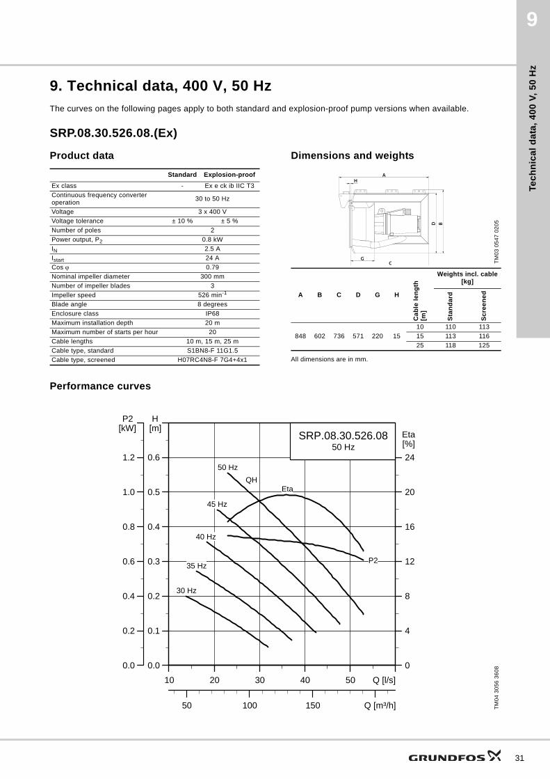
9. Technical data, 400 V, 50 Hz
The curves on the following pages apply to both standard and explosion-proof pump versions when available.
SRP.08.30.526.08.(Ex)
Product data Dimensions and weights
All dimensions are in mm.
Performance curves
Standard Explosion-proof
Ex class - Ex e ck ib IIC T3
Continuous frequency converter operation
30 to 50 Hz
Voltage 3 x 400 V
Voltage tolerance ± 10 % ± 5 %
Number of poles 2
Power output, P2 0.8 kW
IN 2.5 A
Istart 24 A
Cos 0.79
Nominal impeller diameter 300 mm
Number of impeller blades 3
Impeller speed 526 min-1
Blade angle 8 degrees
Enclosure class IP68
Maximum installation depth 20 m
Maximum number of starts per hour 20
Cable lengths 10 m, 15 m, 25 m
Cable type, standard S1BN8-F 11G1.5
Cable type, screened H07RC4N8-F 7G4+4x1
TM
03
05
47
02
05
A B C D G H
Ca
ble
le
ng
th[m
]
Weights incl. cable[kg]
Sta
nd
ard
Sc
ree
ne
d
848 602 736 571 220 15
10 110 113
15 113 116
25 118 125
AH
CG
BD
TM
04
30
56
36
08
10 20 30 40 50 Q [l/s]
0.0
0.1
0.2
0.3
0.4
0.5
0.6
[m]H
50 100 150 Q [m³/h]
0
4
8
12
16
20
24
[%]EtaSRP.08.30.526.08
50 Hz
50 Hz
30 Hz
35 Hz
40 Hz
45 Hz
Eta
P2
QH
10 20 30 40 50 Q [l/s]
0.0
0.2
0.4
0.6
0.8
1.0
1.2
[kW]P2
31

Tec
hn
ica
l da
ta, 4
00
V, 5
0 H
z
32
9
SRP.10.30.606.08(.Ex)
Product dataDimensions and weights
All dimensions are in mm.
Performance curves
Standard Explosion-proof
Ex class - Ex e ck ib IIC T3
Continuous frequency converter operation
30 to 50 Hz
Voltage 3 x 400 V
Voltage tolerance ± 10 % ± 5 %
Number of poles 2
Power output, P2 1 kW
IN 2.8 A
Istart 24 A
Cos 0.83
Nominal impeller diameter 300 mm
Number of impeller blades 3
Impeller speed 606 min-1
Blade angle 8 degrees
Enclosure class IP68
Maximum installation depth 20 m
Maximum number of starts per hour 20
Cable lengths 10 m, 15 m, 25 m
Cable type, standard S1BN8-F 11G1.5
Cable type, screened H07RC4N8-F 7G4+4x1
TM
03
05
47
02
05
A B C D G H
Ca
ble
le
ng
th[m
]
Weights incl. cable[kg]
Sta
nd
ard
Sc
ree
ne
d
848 602 736 571 220 15
10 110 113
15 113 116
25 118 125
AH
CG
BD
TM
04
30
57
36
08
10 20 30 40 50 60 70 Q [l/s]
0.0
0.1
0.2
0.3
0.4
0.5
0.6
0.7
0.8
[m]H
50 100 150 200 Q [m³/h]
0
4
8
12
16
20
24
28
[%]Eta
SRP.10.30.606.0850 Hz
Eta
50 Hz
30 Hz
35 Hz
40 Hz
45 Hz
P2
QH
10 20 30 40 50 60 70 Q [l/s]
0.0
0.2
0.4
0.6
0.8
1.0
1.2
1.4
1.6
[kW]P2

Tec
hn
ica
l d
ata
, 4
00
V,
50
Hz
9
SRP.13.30.678.08(.Ex)
Product dataDimensions and weights
Performance curves
Standard Explosion-proof
Ex class - Ex e ck ib IIC T3
Continuous frequency converter operation
30 to 50 Hz
Voltage 3 x 400 V
Voltage tolerance ± 10 % ± 5 %
Number of poles 2
Power output, P2 1.3 kW
IN 3.2 A
Istart 24 A
Cos 0.87
Nominal impeller diameter 300 mm
Number of impeller blades 3
Impeller speed 678 min-1
Blade angle 8 degrees
Enclosure class IP68
Maximum installation depth 20 m
Maximum number of starts per hour 20
Cable lengths 10 m, 15 m, 25 m
Cable type, standard S1BN8-F 11G1.5
Cable type, screened H07RC4N8-F 7G4+4x1
TM
03
05
47
02
05
A B C D G H
Ca
ble
le
ng
th[m
]
Weights incl. cable[kg]
Sta
nd
ard
Sc
ree
ne
d
848 602 736 571 220 15
10 110 113
15 113 116
25 118 125
AH
CG
BD
TM
04
30
58
36
0810 20 30 40 50 60 70 Q [l/s]
0.0
0.1
0.2
0.3
0.4
0.5
0.6
0.7
0.8
0.9
1.0
[m]H
50 100 150 200 250 Q [m³/h]
0
4
8
12
16
20
24
28
32
36
[%]Eta
SRP.13.30.678.0850 Hz
50 Hz
30 Hz
35 Hz
45 Hz
40 HzEta
P2
QH
10 20 30 40 50 60 70 80Q [l/s]
0.0
0.2
0.4
0.6
0.8
1.0
1.2
1.4
1.6
1.8
2.0
[kW]P2
33

Tec
hn
ica
l da
ta, 4
00
V, 5
0 H
z
34
9
SRP.16.30.745.08(.Ex)
Product dataDimensions and weights
Performance curves
Standard Explosion-proof
Ex class - Ex e ck ib IIC T3
Continuous frequency converter operation
30 to 50 Hz
Voltage 3 x 400 V
Voltage tolerance ± 10 % ± 5 %
Number of poles 2
Power output, P2 1.6 kW
IN 3.8 A
Istart 24 A
Cos 0.89
Nominal impeller diameter 300 mm
Number of impeller blades 3
Impeller speed 745 min-1
Blade angle 8 degrees
Enclosure class IP68
Maximum installation depth 20 m
Maximum number of starts per hour 20
Cable lengths 10 m, 15 m, 25 m
Cable type, standard S1BN8-F 11G1.5
Cable type, screened H07RC4N8-F 7G4+4x1
TM
03
05
47
02
05
A B C D G H
Ca
ble
le
ng
th[m
]
Weights incl. cable[kg]
Sta
nd
ard
Sc
ree
ne
d
848 602 736 571 220 15
10 110 113
15 113 116
25 118 125
AH
CG
BD
TM
04
30
59
36
08
10 20 30 40 50 60 70 80 Q [l/s]
0.0
0.1
0.2
0.3
0.4
0.5
0.6
0.7
0.8
0.9
1.0
1.1
1.2
1.3[m]H
50 100 150 200 250 300 Q [m³/h]
0
4
8
12
16
20
24
28
32
36
[%]Eta
SRP.16.30.745.0850 Hz
50 Hz
30 Hz
35 Hz
40 Hz
45 Hz
Eta
P2
QH
10 20 30 40 50 60 70 80 Q [l/s]
0.0
0.2
0.4
0.6
0.8
1.0
1.2
1.4
1.6
1.8
2.0
2.2
2.4
2.6[kW]P2

Tec
hn
ica
l d
ata
, 4
00
V,
50
Hz
9
SRP.18.30.806.08(.Ex)
Product data Dimensions and weights
All dimensions are in mm.
Performance curves
Standard Explosion-proof
Ex class - Ex e ck ib IIC T3
Continuous frequency converter operation
30 to 50 Hz
Voltage 3 x 400 V
Voltage tolerance ± 10 % ± 5 %
Number of poles 2
Power output, P2 1.8 kW
IN 4.2 A
Istart 24 A
Cos 0.90
Nominal impeller diameter 300 mm
Number of impeller blades 3
Impeller speed 806 min-1
Blade angle 8 degrees
Enclosure class IP68
Maximum installation depth 20 m
Maximum number of starts per hour 20
Cable lengths 10 m, 15 m, 25 m
Cable type, standard S1BN8-F 11G1.5
Cable type, screened H07RC4N8-F 7G4+4x1
TM
03
05
47
02
05
A B C D G H
Ca
ble
le
ng
th[m
]
Weights incl. cable[kg]
Sta
nd
ard
Sc
ree
ne
d
848 602 736 571 220 15
10 110 113
15 113 116
25 118 125
AH
CG
BD
TM
04
30
60
36
08
10 20 30 40 50 60 70 80 Q [l/s]
0.0
0.2
0.4
0.6
0.8
1.0
1.2
1.4
1.6
[m]H
50 100 150 200 250 300 Q [m³/h]
0
5
10
15
20
25
30
35
[%]Eta
SRP.18.30.806.0850 Hz
50 Hz
30 Hz
35 Hz
40 Hz
45 Hz
Eta
P2
QH
10 20 30 40 50 60 70 80 Q [l/s]
0.0
0.4
0.8
1.2
1.6
2.0
2.4
2.8
3.2
[kW]P2
35

Tec
hn
ica
l da
ta, 4
00
V, 5
0 H
z
36
9
SRP.30.30.517.25(.Ex)
Product dataDimensions and weights
Performance curves
Standard Explosion-proof
Ex class - Ex e ck ib IIC T3
Continuous frequency converter operation
30 to 50 Hz
Voltage 3 x 400 V
Voltage tolerance ± 10 % ± 5 %
Number of poles 2
Power output, P2 3.0 kW
IN 6.7 A
Istart 56 A
Cos 0.83
Nominal impeller diameter 300 mm
Number of impeller blades 3
Impeller speed 517 min-1
Blade angle 25 degrees
Enclosure class IP68
Maximum installation depth 20 m
Maximum number of starts per hour 20
Cable lengths 10 m, 15 m, 25 m
Cable type, standard S1BN8-F 11G1.5
Cable type, screened H07RC4N8-F 7G4+4x1
TM
03
05
47
02
05
A B C D G H
Ca
ble
le
ng
th[m
]
Weights incl. cable[kg]
Sta
nd
ard
Sc
ree
ne
d
848 602 736 571 220 15
10 110 113
15 113 116
25 118 125
AH
CG
BD
TM
02
98
41
51
04
60 80 100 120 140 160 180 Q [l/s]
0.0
0.1
0.2
0.3
0.4
0.5
0.6
0.7
0.8
0.9
[m]H
300 400 500 600 Q [m³/h]
0
5
10
15
20
25
30
35
[%]Eta
SRP.30.30.517.2550 Hz
Eta
QH
45 Hz40 Hz
35 Hz30 Hz
P2
50 Hz
60 80 100 120 140 160 180 Q [l/s]
0.0
0.4
0.8
1.2
1.6
2.0
2.4
2.8
3.2
3.6
[kW]P2

Tec
hn
ica
l d
ata
, 4
00
V,
50
Hz
9
SRP.40.30.593.25
Product data Dimensions and weights
All dimensions are in mm.
Performance curves
Standard
Ex class
Continuous frequency converter operation
30 to 50 Hz
Voltage 3 x 400 V
Voltage tolerance ± 10 %
Number of poles 2
Power output, P2 4 kW
IN 8.2 A
Istart 56 A
Cos 0.87
Nominal impeller diameter 300 mm
Number of impeller blades 3
Impeller speed 593 min-1
Blade angle 25 degrees
Enclosure class IP68
Maximum installation depth 20 m
Maximum number of starts per hour 20
Cable lengths 10 m, 15 m, 25 m
Cable type, standard S1BN8-F 11G1.5
Cable type, screened H07RC4N8-F 7G4+4x1
TM
03
05
47
02
05
A B C D G H
Ca
ble
le
ng
th[m
]
Weights incl. cable[kg]
Sta
nd
ard
Sc
ree
ne
d
848 602 736 571 220 15
10 110 113
15 113 116
25 118 125
AH
CG
BD
TM
02
98
42
51
04
60 80 100 120 140 160 180 200 220 Q [l/s]
0.0
0.1
0.2
0.3
0.4
0.5
0.6
0.7
0.8
0.9
1.0
1.1
[m]H
300 400 500 600 700 800 Q [m³/h]
0
5
10
15
20
25
30
35
40
45
[%]Eta
SRP.40.30.593.2550 Hz
Eta
QH
45 Hz40 Hz
35 Hz30 Hz
P2
50 Hz
60 80 100 120 140 160 180 200 220 Q [l/s]
0.0
0.5
1.0
1.5
2.0
2.5
3.0
3.5
4.0
4.5
5.0
5.5
[kW]P2
37
Tec
hn
ica
l da
ta, 4
00
V, 5
0 H
z
38
9
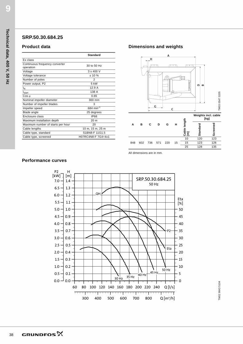
SRP.50.30.684.25
Product data Dimensions and weights
All dimensions are in mm.
Performance curves
Standard
Ex class
Continuous frequency converter operation
30 to 50 Hz
Voltage 3 x 400 V
Voltage tolerance ± 10 %
Number of poles 2
Power output, P2 5 kW
IN 12.9 A
Istart 138 A
Cos 0.65
Nominal impeller diameter 300 mm
Number of impeller blades 3
Impeller speed 684 min-1
Blade angle 25 degrees
Enclosure class IP68
Maximum installation depth 20 m
Maximum number of starts per hour 20
Cable lengths 10 m, 15 m, 25 m
Cable type, standard S1BN8-F 11G1.5
Cable type, screened H07RC4N8-F 7G4+4x1
TM
03
05
47
02
05
A B C D G H
Ca
ble
le
ng
th[m
]
Weights incl. cable[kg]
Sta
nd
ard
Sc
ree
ne
d
848 602 736 571 220 15
10 120 123
15 123 126
25 128 135
AH
CG
BD
TM
02
98
43
51
04
60 80 100 120 140 160 180 200 220 240 Q [l/s]
0.0
0.1
0.2
0.3
0.4
0.5
0.6
0.7
0.8
0.9
1.0
1.1
1.2
1.3
1.4[m]H
300 400 500 600 700 800 Q [m³/h]
0
5
10
15
20
25
30
35
40
45
50
[%]Eta
SRP.50.30.684.2550 Hz
Eta
QH
45 Hz40 Hz
35 Hz30 Hz
P2
50 Hz
60 80 100 120 140 160 180 200 220 240 Q [l/s]
0.0
0.5
1.0
1.5
2.0
2.5
3.0
3.5
4.0
4.5
5.0
5.5
6.0
6.5
7.0[kW]
P2
Tec
hn
ica
l d
ata
, 4
00
V,
50
Hz
9
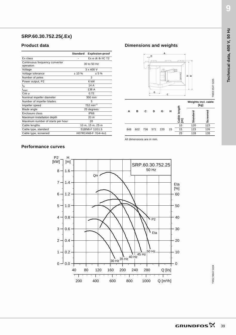
SRP.60.30.752.25(.Ex)
Product data Dimensions and weights
All dimensions are in mm.
Performance curves
Standard Explosion-proof
Ex class - Ex e ck ib IIC T2
Continuous frequency converter operation
30 to 50 Hz
Voltage 3 x 400 V
Voltage tolerance ± 10 % ± 5 %
Number of poles 2
Power output, P2 6 kW
IN 14 A
Istart 138 A
Cos 0.72
Nominal impeller diameter 300 mm
Number of impeller blades 3
Impeller speed 752 min-1
Blade angle 25 degrees
Enclosure class IP68
Maximum installation depth 20 m
Maximum number of starts per hour 20
Cable lengths 10 m, 15 m, 25 m
Cable type, standard S1BN8-F 11G1.5
Cable type, screened H07RC4N8-F 7G4+4x1
TM
03
05
47
02
05
A B C D G H
Ca
ble
le
ng
th[m
]
Weights incl. cable[kg]
Sta
nd
ard
Sc
ree
ne
d
848 602 736 571 220 15
10 120 123
15 123 126
25 128 135
AH
CG
BD
TM
02
98
44
51
04
40 80 120 160 200 240 280 Q [l/s]
0.0
0.2
0.4
0.6
0.8
1.0
1.2
1.4
1.6
[m]H
200 400 600 800 1000 Q [m³/h]
0
10
20
30
40
50
60
[%]Eta
SRP.60.30.752.2550 Hz
Eta
QH
45 Hz40 Hz
35 Hz30 Hz
P2
50 Hz
40 80 120 160 200 240 280 Q [l/s]
0
1
2
3
4
5
6
7
8
[kW]P2
39

Tec
hn
ica
l da
ta, 4
00
V, 5
0 H
z
40
9
SRP.70.30.814.25(.Ex)
Product data Dimensions and weights
All dimensions are in mm.
Performance curves
Standard Explosion-proof
Ex class - Ex e ck ib IIC T2
Continuous frequency converter operation
30 to 50 Hz
Voltage 3 x 400 V
Voltage tolerance ± 10 % ± 5 %
Number of poles 2
Power output, P2 7 kW
IN 15.4 A
Istart 138 A
Cos 0.77
Nominal impeller diameter 300 mm
Number of impeller blades 3
Impeller speed 814 min-1
Blade angle 25 degrees
Enclosure class IP68
Maximum installation depth 20 m
Maximum number of starts per hour 20
Cable lengths 10 m, 15 m, 25 m
Cable type, standard S1BN8-F 11G1.5
Cable type, screened H07RC4N8-F 7G4+4x1
TM
03
05
47
02
05
A B C D G H
Ca
ble
le
ng
th[m
]
Weights incl. cable[kg]
Sta
nd
ard
Sc
ree
ne
d
848 602 736 571 220 15
10 120 123
15 123 126
25 128 135
AH
CG
BD
TM
02
98
45
51
04
40 80 120 160 200 240 280 Q [l/s]
0.0
0.2
0.4
0.6
0.8
1.0
1.2
1.4
1.6
1.8
2.0
[m]H
200 400 600 800 1000 Q [m³/h]
0
10
20
30
40
50
60
[%]Eta
SRP.70.30.814.2550 Hz
Eta
QH
45 Hz40 Hz
35 Hz30 Hz
P2
50 Hz
40 80 120 160 200 240 280 Q [l/s]
0
1
2
3
4
5
6
7
8
9
10
[kW]P2

Tec
hn
ica
l d
ata
, 4
00
V,
50
Hz
9
SRP.35.50.257.27(.Ex)
Product data Dimensions and weights
All dimensions are in mm.
Performance curves
Standard Explosion-proof
Ex class - Ex e ck ib IIC T3
Continuous frequency converter operation
30 to 50 Hz
Voltage 3 x 400 V
Voltage tolerance ± 10 % ± 5 %
Number of poles 4
Power output, P2 3.5 kW
IN 11.6 A
Istart 76 A
Cos 0.60
Nominal impeller diameter 500 mm
Number of impeller blades 3
Impeller speed 257 min-1
Blade angle 27 degrees
Enclosure class IP68
Maximum installation depth 20 m
Maximum number of starts per hour 20
Cable lengths 10 m, 15 m, 25 m
Cable type, standard S1BN8-F 11G1.5
Cable type, screened H07RC4N8-F 7G4+4x1
TM
03
05
47
02
05
A B C D G H
Ca
ble
le
ng
th[m
]
Weights incl. cable[kg]
Sta
nd
ard
Sc
ree
ne
d
910 835 787 824 230 25
10 200 203
15 203 206
25 208 215
AH
CG
BD
TM
02
98
46
51
04
120 160 200 240 280 320 360 400 440 Q [l/s]
0.00
0.05
0.10
0.15
0.20
0.25
0.30
0.35
0.40
0.45
0.50
0.55
0.60
[m]H
600 800 1000 1200 1400 1600 Q [m³/h]
0
5
10
15
20
25
30
35
40
45
50
55
[%]EtaSRP.35.50.257.27
50 Hz
Eta
QH
45 Hz40 Hz
35 Hz30 Hz
P2
50 Hz
120 160 200 240 280 320 360 400 440 Q [l/s]
0.0
0.5
1.0
1.5
2.0
2.5
3.0
3.5
4.0
4.5
5.0
5.5
6.0
[kW]P2
41

Tec
hn
ica
l da
ta, 4
00
V, 5
0 H
z
42
9
SRP.50.50.291.27(.Ex)
Product data Dimensions and weights
All dimensions are in mm.
Performance curves
Standard Explosion-proof
Ex class - Ex e ck ib IIC T3
Continuous frequency converter operation
30 to 50 Hz
Voltage 3 x 400 V
Voltage tolerance ± 10 % ± 5 %
Number of poles 4
Power output, P2 5 kW
IN 13.6 A
Istart 76 A
Cos 0.73
Nominal impeller diameter 500 mm
Number of impeller blades 3
Impeller speed 291 min-1
Blade angle 27 degrees
Enclosure class IP68
Maximum installation depth 20 m
Maximum number of starts per hour 20
Cable lengths 10 m, 15 m, 25 m
Cable type, standard S1BN8-F 11G1.5
Cable type, screened H07RC4N8-F 7G4+4x1
TM
03
05
47
02
05
A B C D G H
Ca
ble
le
ng
th[m
]
Weights incl. cable[kg]
Sta
nd
ard
Sc
ree
ne
d
910 835 787 824 230 25
10 200 203
15 203 206
25 208 215
AH
CG
BD
TM
02
98
47
51
04
100 150 200 250 300 350 400 450 500 Q [l/s]
0.0
0.1
0.2
0.3
0.4
0.5
0.6
0.7
0.8
[m]H
400 800 1200 1600 Q [m³/h]
0
10
20
30
40
50
60
[%]Eta
SRP.50.50.291.2750 Hz
Eta
QH
45 Hz40 Hz35 Hz30 Hz
P2
50 Hz
100 150 200 250 300 350 400 450 500 Q [l/s]
0
1
2
3
4
5
6
7
8
[kW]P2
Tec
hn
ica
l d
ata
, 4
00
V,
50
Hz
9
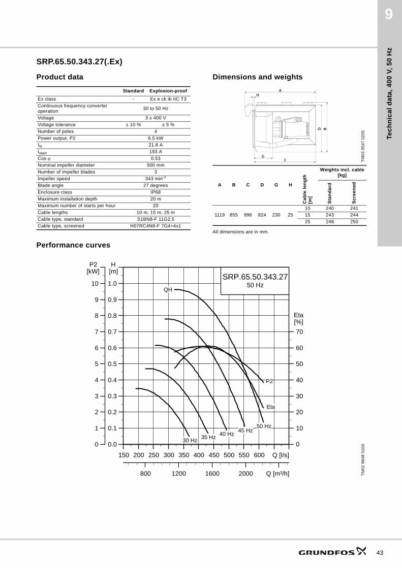
SRP.65.50.343.27(.Ex)
Product data Dimensions and weights
All dimensions are in mm.
Performance curves
Standard Explosion-proof
Ex class - Ex e ck ib IIC T3
Continuous frequency converter operation
30 to 50 Hz
Voltage 3 x 400 V
Voltage tolerance ± 10 % ± 5 %
Number of poles 4
Power output, P2 6.5 kW
IN 21.8 A
Istart 193 A
Cos 0.53
Nominal impeller diameter 500 mm
Number of impeller blades 3
Impeller speed 343 min-1
Blade angle 27 degrees
Enclosure class IP68
Maximum installation depth 20 m
Maximum number of starts per hour 20
Cable lengths 10 m, 15 m, 25 m
Cable type, standard S1BN8-F 11G2.5
Cable type, screened H07RC4N8-F 7G4+4x1
TM
03
05
47
02
05
A B C D G H
Ca
ble
le
ng
th[m
]
Weights incl. cable[kg]
Sta
nd
ard
Sc
ree
ne
d
1119 855 996 824 230 25
10 240 241
15 243 244
25 248 250
AH
CG
BD
TM
02
98
48
51
04
150 200 250 300 350 400 450 500 550 600 Q [l/s]
0.0
0.1
0.2
0.3
0.4
0.5
0.6
0.7
0.8
0.9
1.0
[m]H
800 1200 1600 2000 Q [m³/h]
0
10
20
30
40
50
60
70
[%]Eta
SRP.65.50.343.2750 Hz
Eta
QH
45 Hz40 Hz
35 Hz30 Hz
P2
50 Hz
150 200 250 300 350 400 450 500 550 600 Q [l/s]
0
1
2
3
4
5
6
7
8
9
10
[kW]P2
43

Tec
hn
ica
l da
ta, 4
00
V, 5
0 H
z
44
9
SRP.80.50.378.27(.Ex)
Product data Dimensions and weights
All dimensions are in mm.
Performance curves
Standard Explosion-proof
Ex class - Ex e ck ib IIC T3
Continuous frequency converter operation
30 to 50 Hz
Voltage 3 x 400 V
Voltage tolerance ± 10 % ± 5 %
Number of poles 4
Power output, P2 8 kW
IN 23.2 A
Istart 193 A
Cos 0.61
Nominal impeller diameter 500 mm
Number of impeller blades 3
Impeller speed 378 min-1
Blade angle 27 degrees
Enclosure class IP68
Maximum installation depth 20 m
Maximum number of starts per hour 20
Cable lengths 10 m, 15 m, 25 m
Cable type, standard S1BN8-F 11G2.5
Cable type, screened H07RC4N8-F 7G4+4x1
TM
03
05
47
02
05
A B C D G H
Ca
ble
le
ng
th[m
]
Weights incl. cable[kg]
Sta
nd
ard
Sc
ree
ne
d
1119 855 996 824 230 25
10 240 241
15 243 244
25 248 250
AH
CG
BD
TM
02
98
49
51
04
200 250 300 350 400 450 500 550 600 650 Q [l/s]
0.0
0.1
0.2
0.3
0.4
0.5
0.6
0.7
0.8
0.9
1.0
1.1
[m]H
800 1200 1600 2000 Q [m³/h]
0
10
20
30
40
50
60
70
[%]Eta
SRP.80.50.378.2750 Hz
Eta
QH
45 Hz40 Hz
35 Hz30 Hz
P2
50 Hz
200 250 300 350 400 450 500 550 600 650 Q [l/s]
0
1
2
3
4
5
6
7
8
9
10
11
[kW]P2

Tec
hn
ica
l d
ata
, 4
00
V,
50
Hz
9
SRP.100.50.412.27
Product data Dimensions and weights
All dimensions are in mm.
Performance curves
Standard
Ex class
Continuous frequency converter operation
30 to 50 Hz
Voltage 3 x 400 V
Voltage tolerance ± 10 %
Number of poles 4
Power output, P2 10 kW
IN 24.4 A
Istart 259 A
Cos 0.68
Nominal impeller diameter 500 mm
Number of impeller blades 3
Impeller speed 412 min-1
Blade angle 27 degrees
Enclosure class IP68
Maximum installation depth 20 m
Maximum number of starts per hour 20
Cable lengths 10 m, 15 m, 25 m
Cable type, standard S1BN8-F 11G2.5
Cable type, screened H07RC4N8-F 7G4+4x1
TM
03
05
47
02
05
A B C D G H
Ca
ble
le
ng
th[m
]
Weights incl. cable[kg]
Sta
nd
ard
Sc
ree
ne
d
1119 855 996 824 230 25
10 250 251
15 253 254
25 258 260
AH
CG
BD
TM
02
98
50
51
04
200 250 300 350 400 450 500 550 600 650 700 750 Q [l/s]
0.0
0.2
0.4
0.6
0.8
1.0
1.2
1.4
1.6
[m]H
800 1200 1600 2000 2400 Q [m³/h]
0
10
20
30
40
50
60
70
[%]Eta
SRP.100.50.412.2750 Hz
Eta
QH
45 Hz40 Hz
35 Hz30 Hz
P2
50 Hz
200 250 300 350 400 450 500 550 600 650 700 750 Q [l/s]
0
2
4
6
8
10
12
14
16
[kW]P2
45
Tec
hn
ica
l da
ta, 4
00
V, 5
0 H
z
46
9
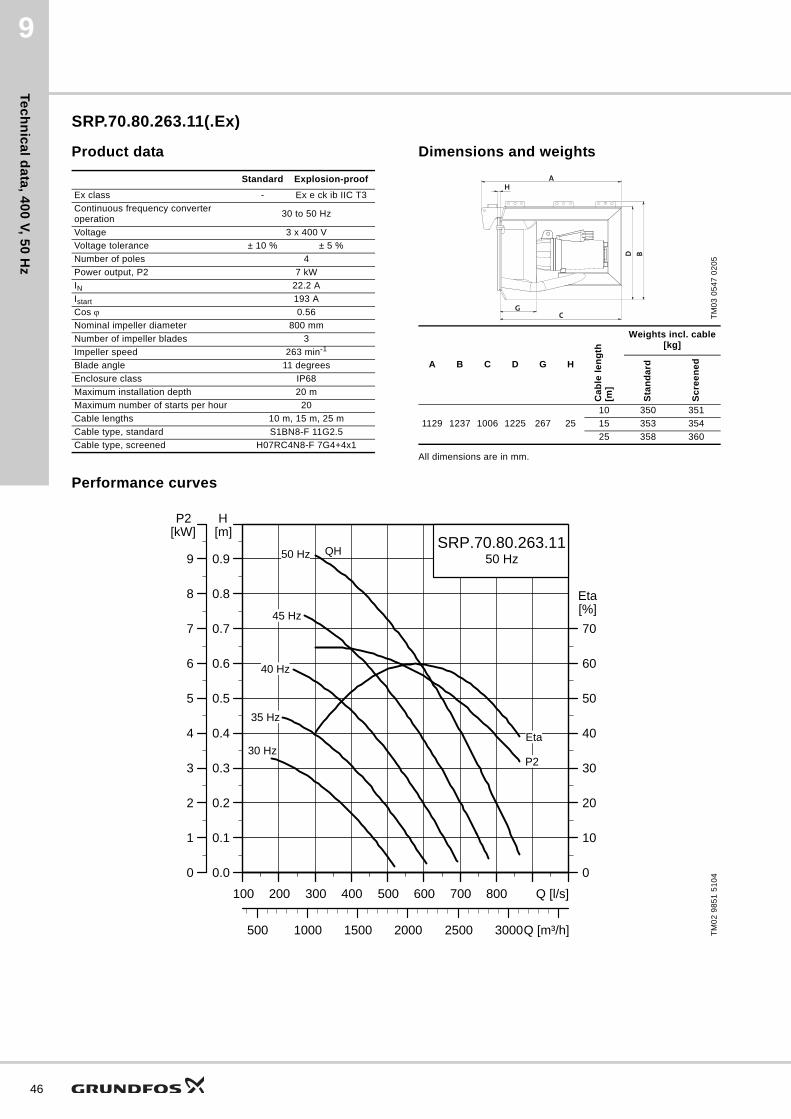
SRP.70.80.263.11(.Ex)
Product data Dimensions and weights
All dimensions are in mm.
Performance curves
Standard Explosion-proof
Ex class - Ex e ck ib IIC T3
Continuous frequency converter operation
30 to 50 Hz
Voltage 3 x 400 V
Voltage tolerance ± 10 % ± 5 %
Number of poles 4
Power output, P2 7 kW
IN 22.2 A
Istart 193 A
Cos 0.56
Nominal impeller diameter 800 mm
Number of impeller blades 3
Impeller speed 263 min-1
Blade angle 11 degrees
Enclosure class IP68
Maximum installation depth 20 m
Maximum number of starts per hour 20
Cable lengths 10 m, 15 m, 25 m
Cable type, standard S1BN8-F 11G2.5
Cable type, screened H07RC4N8-F 7G4+4x1
TM
03
05
47
02
05
A B C D G H
Ca
ble
le
ng
th[m
]
Weights incl. cable[kg]
Sta
nd
ard
Sc
ree
ne
d
1129 1237 1006 1225 267 25
10 350 351
15 353 354
25 358 360
AH
CG
BD
TM
02
98
51
51
04
100 200 300 400 500 600 700 800 Q [l/s]
0.0
0.1
0.2
0.3
0.4
0.5
0.6
0.7
0.8
0.9
[m]H
500 1000 1500 2000 2500 3000Q [m³/h]
0
10
20
30
40
50
60
70
[%]Eta
SRP.70.80.263.1150 Hz
Eta
QH
45 Hz
40 Hz
35 Hz
30 HzP2
50 Hz
100 200 300 400 500 600 700 800 Q [l/s]
0
1
2
3
4
5
6
7
8
9
[kW]P2

Tec
hn
ica
l d
ata
, 4
00
V,
50
Hz
9
SRP.100.80.303.11
Product data Dimensions and weights
All dimensions are in mm.
Performance curves
Standard
Ex class
Continuous frequency converter operation
30 to 50 Hz
Voltage 3 x 400 V
Voltage tolerance ± 10 %
Number of poles 4
Power output, P2 10 kW
IN 24.4 A
Istart 259 A
Cos 0.68
Nominal impeller diameter 800 mm
Number of impeller blades 3
Impeller speed 303 min-1
Blade angle 11 degrees
Enclosure class IP68
Maximum installation depth 20 m
Maximum number of starts per hour 20
Cable lengths 10 m, 15 m, 25 m
Cable type, standard S1BN8-F 11G2.5
Cable type, screened H07RC4N8-F 7G4+4x1
TM
03
05
47
02
05
A B C D G H
Ca
ble
le
ng
th[m
]
Weights incl. cable[kg]
Sta
nd
ard
Sc
ree
ne
d
1129 1237 1006 1225 267 25
10 360 361
15 363 364
25 368 370
AH
CG
BD
TM
02
98
52
51
04
100 200 300 400 500 600 700 800 900 1000 Q [l/s]
0.0
0.1
0.2
0.3
0.4
0.5
0.6
0.7
0.8
0.9
1.0
1.1
1.2
1.3
[m]H
500 1000 1500 2000 2500 3000 3500 Q [m³/h]
0
10
20
30
40
50
60
70
[%]Eta
SRP.100.80.303.1150 Hz
Eta
QH
45 Hz
40 Hz
35 Hz
30 HzP2
50 Hz
100 200 300 400 500 600 700 800 900 1000 Q [l/s]
0
1
2
3
4
5
6
7
8
9
10
11
12
13
[kW]P2
47

Tec
hn
ica
l da
ta, 4
00
V, 5
0 H
z
48
9
SRP.120.80.323.11(.Ex)
Product data Dimensions and weights
All dimensions are in mm.
Performance curves
Standard Explosion-proof
Ex class - Ex e ck ib IIC T3
Continuous frequency converter operation
30 to 50 Hz
Voltage 3 x 400 V
Voltage tolerance ± 10 % ± 5 %
Number of poles 4
Power output, P2 12 kW
IN 30.3 A
Istart 284 A
Cos 0.64
Nominal impeller diameter 800 mm
Number of impeller blades 3
Impeller speed 323 min-1
Blade angle 11 degrees
Enclosure class IP68
Maximum installation depth 20 m
Maximum number of starts per hour 20
Cable lengths 10 m, 15 m, 25 m
Cable type, standard H07RN-F 7G4+4x1
Cable type, screened H07RC4N8-F 7G4+4x1
TM
03
05
47
02
05
A B C D G H
Ca
ble
le
ng
th[m
]
Weights incl. cable[kg]
Sta
nd
ard
Sc
ree
ne
d
1181 1257 1058 1225 267 25
10 405 406
15 408 409
25 413 415
AH
CG
BD
TM
02
98
53
51
04
150 200 250 300 350 400 450 500 550 600 Q [l/s]
0.0
0.1
0.2
0.3
0.4
0.5
0.6
0.7
0.8
0.9
1.0
1.1
1.2
1.3
1.4
1.5[m]H
600 800 1000 1200 1400 1600 1800 2000 Q [m³/h]
0
5
10
15
20
25
30
35
40
45
50
55
60
65
[%]Eta
SRP.120.80.323.1150 Hz
Eta
QH
45 Hz
40 Hz
35 Hz
30 HzP2
50 Hz
150 200 250 300 350 400 450 500 550 600 Q [l/s]
0
2
4
6
8
10
12
14
16
18
20
22
24
26
28
30[kW]P2

Tec
hn
ica
l d
ata
, 4
00
V,
50
Hz
9
SRP.130.80.340.11(.Ex)
Product data Dimensions and weights
All dimensions are in mm.
Performance curves
Standard Explosion-proof
Ex class - Ex e ck ib IIC T3
Continuous frequency converter operation
30 to 50 Hz
Voltage 3 x 400 V
Voltage tolerance ± 10 % ± 5 %
Number of poles 4
Power output, P2 13 kW
IN 27.8 A
Istart 259 A
Cos 0.77
Nominal impeller diameter 800 mm
Number of impeller blades 3
Impeller speed 340 min-1
Blade angle 11 degrees
Enclosure class IP68
Maximum installation depth 20 m
Maximum number of starts per hour 20
Cable lengths 10 m, 15 m, 25 m
Cable type, standard S1BN8-F 11G2.5
Cable type, screened H07RC4N8-F 7G4+4x1
TM
03
05
47
02
05
A B C D G H
Ca
ble
le
ng
th[m
]
Weights incl. cable[kg]
Sta
nd
ard
Sc
ree
ne
d
1129 1237 1006 1225 267 25
10 360 361
15 363 364
25 368 370
AH
CG
BD
TM
02
98
54
51
04
200 300 400 500 600 700 800 900 1000 1100 Q [l/s]
0.0
0.1
0.2
0.3
0.4
0.5
0.6
0.7
0.8
0.9
1.0
1.1
1.2
1.3
1.4
1.5[m]H
1000 1500 2000 2500 3000 3500 Q [m³/h]
0
5
10
15
20
25
30
35
40
45
50
55
60
65
[%]Eta
SRP.130.80.340.1150 Hz
Eta
QH
45 Hz
40 Hz
35 Hz
30 Hz
P2
50 Hz
200 300 400 500 600 700 800 900 1000 1100 Q [l/s]
0
2
4
6
8
10
12
14
16
18
20
22
24
26
28
30[kW]P2
49
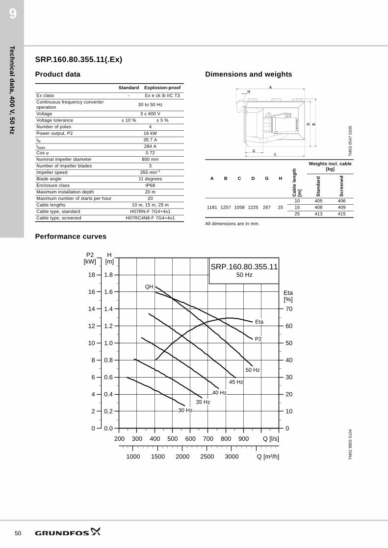
Tec
hn
ica
l da
ta, 4
00
V, 5
0 H
z
50
9
SRP.160.80.355.11(.Ex)
Product data Dimensions and weights
All dimensions are in mm.
Performance curves
Standard Explosion-proof
Ex class - Ex e ck ib IIC T3
Continuous frequency converter operation
30 to 50 Hz
Voltage 3 x 400 V
Voltage tolerance ± 10 % ± 5 %
Number of poles 4
Power output, P2 16 kW
IN 35.7 A
Istart 284 A
Cos 0.72
Nominal impeller diameter 800 mm
Number of impeller blades 3
Impeller speed 355 min-1
Blade angle 11 degrees
Enclosure class IP68
Maximum installation depth 20 m
Maximum number of starts per hour 20
Cable lengths 10 m, 15 m, 25 m
Cable type, standard H07RN-F 7G4+4x1
Cable type, screened H07RC4N8-F 7G4+4x1
TM
03
05
47
02
05
A B C D G H
Ca
ble
le
ng
th[m
]
Weights incl. cable[kg]
Sta
nd
ard
Sc
ree
ne
d
1181 1257 1058 1225 267 25
10 405 406
15 408 409
25 413 415
AH
CG
BD
TM
02
98
55
51
04
200 300 400 500 600 700 800 900 Q [l/s]
0.0
0.2
0.4
0.6
0.8
1.0
1.2
1.4
1.6
1.8
[m]H
1000 1500 2000 2500 3000 Q [m³/h]
0
10
20
30
40
50
60
70
[%]Eta
SRP.160.80.355.1150 Hz
Eta
QH
45 Hz
40 Hz
35 Hz
30 Hz
P2
50 Hz
200 300 400 500 600 700 800 900 Q [l/s]
0
2
4
6
8
10
12
14
16
18
[kW]P2

Tec
hn
ica
l d
ata
, 4
00
V,
50
Hz
9
SRP.130.80.375.11(.Ex)
Product data Dimensions and weights
All dimensions are in mm.
Performance curves
Standard Explosion-proof
Ex class - Ex e ck ib IIC T3
Continuous frequency converter operation
30 to 50 Hz
Voltage 3 x 400 V
Voltage tolerance ± 10 % ± 5 %
Number of poles 4
Power output, P2 13 kW
IN 27.8 A
Istart 259 A
Cos 0.77
Nominal impeller diameter 800 mm
Number of impeller blades 3
Impeller speed 375 min-1
Blade angle 11 degrees
Enclosure class IP68
Maximum installation depth 20 m
Maximum number of starts per hour 20
Cable lengths 10 m, 15 m, 25 m
Cable type, standard S1BN8-F 11G2.5
Cable type, screened H07RC4N8-F 7G4+4x1
TM
03
05
47
02
05
A B C D G H
Ca
ble
le
ng
th[m
]
Weights incl. cable[kg]
Sta
nd
ard
Sc
ree
ne
d
1129 1237 1006 1225 267 25
10 360 361
15 363 364
25 368 370
AH
CG
BD
TM
02
98
56
51
04
500 600 700 800 900 1000 1100 1200 Q [l/s]
0.0
0.1
0.2
0.3
0.4
0.5
0.6
0.7
0.8
0.9
1.0
[m]H
2000 2500 3000 3500 4000 Q [m³/h]
0
10
20
30
40
50
60
70
[%]Eta
SRP.130.80.375.1150 Hz
Eta
QH
45 Hz40 Hz35 Hz30 Hz
P2
50 Hz
500 600 700 800 900 1000 1100 1200 Q [l/s]
0
2
4
6
8
10
12
14
16
18
20
[kW]P2
51

Tec
hn
ica
l da
ta, 4
00
V, 5
0 H
z
52
9
SRP.200.80.388.11(.Ex)
Product data Dimensions and weights
All dimensions are in mm.
Performance curves
Standard Explosion-proof
Ex class - Ex e ck ib IIC T3
Continuous frequency converter operation
30 to 50 Hz
Voltage 3 x 400 V
Voltage tolerance ± 10 % ± 5 %
Number of poles 4
Power output, P2 20 kW
IN 50.3 A
Istart 423 A
Cos 0.64
Nominal impeller diameter 800 mm
Number of impeller blades 3
Impeller speed 388 min-1
Blade angle 11 degrees
Enclosure class IP68
Maximum installation depth 20 m
Maximum number of starts per hour 20
Cable lengths 10 m, 15 m, 25 m
Cable type, standard H07RN-F 7G4+4x1
Cable type, screened H07RC4N8-F 7G4+4x1
TM
03
05
47
02
05
A B C D G H
Ca
ble
le
ng
th[m
]
Weights incl. cable[kg]
Sta
nd
ard
Sc
ree
ne
d
1181 1257 1058 1225 267 25
10 430 431
15 433 434
25 438 440
AH
CG
BD
TM
02
98
57
51
04
200 250 300 350 400 450 500 550 600 650 Q [l/s]
0.0
0.2
0.4
0.6
0.8
1.0
1.2
1.4
1.6
1.8
2.0
2.2
[m]H
800 1200 1600 2000 Q [m³/h]
0
10
20
30
40
50
60
70
[%]Eta
SRP.200.80.388.1150 Hz
Eta
QH
45 Hz
40 Hz
35 Hz
30 Hz
P2
50 Hz
200 250 300 350 400 450 500 550 600 650 Q [l/s]
0
4
8
12
16
20
24
28
32
36
40
44
[kW]P2

Tec
hn
ica
l d
ata
, 4
00
V,
50
Hz
9
SRP.180.80.387.11(.Ex)
Product data Dimensions and weights
All dimensions are in mm.
Performance curves
Standard Explosion-proof
Ex class - Ex e ck ib IIC T3
Continuous frequency converter operation
30 to 50 Hz
Voltage 3 x 400 V
Voltage tolerance ± 10 % ± 5 %
Number of poles 4
Power output, P2 18 kW
IN 38 A
Istart 284 A
Cos 0.76
Nominal impeller diameter 800 mm
Number of impeller blades 3
Impeller speed 387 min-1
Blade angle 11 degrees
Enclosure class IP68
Maximum installation depth 20 m
Maximum number of starts per hour 20
Cable lengths 10 m, 15 m, 25 m
Cable type, standard H07RN-F 7G4+4x1
Cable type, screened H07RC4N8-F 7G4+4x1
TM
03
05
47
02
05
A B C D G H
Ca
ble
le
ng
th[m
]
Weights incl. cable[kg]
Sta
nd
ard
Sc
ree
ne
d
1181 1257 1058 1225 267 25
10 405 406
15 408 409
25 413 415
AH
CG
BD
TM
02
98
58
51
04
300 400 500 600 700 800 900 10001100 1200 Q [l/s]
0.0
0.2
0.4
0.6
0.8
1.0
1.2
1.4
1.6
[m]H
1500 2000 2500 3000 3500 4000 Q [m³/h]
0
10
20
30
40
50
60
70
[%]Eta
SRP.180.80.387.1150 Hz
Eta
QH
45 Hz
40 Hz
35 Hz
30 Hz
P2
50 Hz
300 400 500 600 700 800 900 10001100 1200 Q [l/s]
0
4
8
12
16
20
24
28
32
[kW]P2
53

Tec
hn
ica
l da
ta, 4
00
V, 5
0 H
z
54
9
SRP.240.80.417.11
Product data Dimensions and weights
All dimensions are in mm.
Performance curves
Standard
Ex class
Continuous frequency converter operation
30 to 50 Hz
Voltage 3 x 400 V
Voltage tolerance ± 10 %
Number of poles 4
Power output, P2 24 kW
IN 55.4 A
Istart 423 A
Cos 0.70
Nominal impeller diameter 800 mm
Number of impeller blades 3
Impeller speed 417 min-1
Blade angle 11 degrees
Enclosure class IP68
Maximum installation depth 20 m
Maximum number of starts per hour 20
Cable lengths 10 m, 15 m, 25 m
Cable type, standard H07RN-F 7G4+4x1
Cable type, screened H07RC4N8-F 7G4+4x1
TM
03
05
47
02
05
A B C D G H
Ca
ble
le
ng
th[m
]
Weights incl. cable[kg]
Sta
nd
ard
Sc
ree
ne
d
1181 1257 1058 1225 267 25
10 430 341
15 433 434
25 438 440
AH
CG
BD
TM
02
98
59
51
04
200 300 400 500 600 700 800 900 1000 Q [l/s]
0.0
0.2
0.4
0.6
0.8
1.0
1.2
1.4
1.6
1.8
2.0
2.2
[m]H
1000 1500 2000 2500 3000 3500 Q [m³/h]
0
10
20
30
40
50
60
70
[%]Eta
SRP.240.80.417.1150 Hz
Eta
QH
45 Hz
40 Hz
35 Hz
30 HzP2
50 Hz
200 300 400 500 600 700 800 900 1000 Q [l/s]
0
4
8
12
16
20
24
28
32
36
40
44
[kW]P2

Tec
hn
ica
l d
ata
, 4
00
V,
50
Hz
9
SRP.180.80.417.11(.Ex)
Product data Dimensions and weights
All dimensions are in mm.
Performance curves
Standard Explosion-proof
Ex class - Ex e ck ib IIC T3
Continuous frequency converter operation
30 to 50 Hz
Voltage 3 x 400 V
Voltage tolerance ± 10 % ± 5 %
Number of poles 4
Power output, P2 18 kW
IN 38 A
Istart 284 A
Cos 0.76
Nominal impeller diameter 800 mm
Number of impeller blades 3
Impeller speed 417 min-1
Blade angle 11 degrees
Enclosure class IP68
Maximum installation depth 20 m
Maximum number of starts per hour 20
Cable lengths 10 m, 15 m, 25 m
Cable type, standard H07RN-F 7G4+4x1
Cable type, screened H07RC4N8-F 7G4+4x1
TM
03
05
47
02
05
A B C D G H
Ca
ble
le
ng
th[m
]
Weights incl. cable[kg]
Sta
nd
ard
Sc
ree
ne
d
1181 1257 1058 1225 267 25
10 405 406
15 408 409
25 413 415
AH
CG
BD
TM
02
98
60
51
04
500 600 700 800 900 1000 110012001300 1400 Q [l/s]
0.0
0.1
0.2
0.3
0.4
0.5
0.6
0.7
0.8
0.9
1.0
1.1
[m]H
2000 2500 3000 3500 4000 4500 5000 Q [m³/h]
0
10
20
30
40
50
60
70
[%]Eta
SRP.180.80.417.1150 Hz
Eta
QH
45 Hz
40 Hz
35 Hz
30 Hz
P2
50 Hz
500 600 700 800 900 1000 110012001300 1400 Q [l/s]
0
4
8
12
16
20
24
28
32
36
40
44
[kW]P2
55

Tec
hn
ica
l da
ta, 4
15
V, 5
0 H
z
56
10
10. Technical data, 415 V, 50 Hz
SRP.08.30.526.08
Product dataDimensions and weights
Performance curves
Standard
Ex class
Continuous frequency converter operation
30 to 50 Hz
Voltage 3 x 415 V
Voltage tolerance ± 10 %
Number of poles 2
Power output, P2 0.8 kW
IN 2.5 A
Istart 24 A
Cos 0.79
Nominal impeller diameter 300 mm
Number of impeller blades 3
Impeller speed 526 min-1
Blade angle 8 degrees
Enclosure class IP68
Maximum installation depth 20 m
Maximum number of starts per hour 20
Cable lengths 15 m, 25 m
Cable type, standard S1BN8-F 11G1.5
Cable type, screened H07RC4N8-F 7G4+4x1
TM
03
05
47
02
05
A B C D G H
Ca
ble
le
ng
th[m
]
Weights incl. cable[kg]
Sta
nd
ard
Sc
ree
ne
d
848 602 736 571 220 1515 113 116
25 118 125
AH
CG
BD
TM
04
30
56
36
08
10 20 30 40 50 Q [l/s]
0.0
0.1
0.2
0.3
0.4
0.5
0.6
[m]H
50 100 150 Q [m³/h]
0
4
8
12
16
20
24
[%]EtaSRP.08.30.526.08
50 Hz
50 Hz
30 Hz
35 Hz
40 Hz
45 Hz
Eta
P2
QH
10 20 30 40 50 Q [l/s]
0.0
0.2
0.4
0.6
0.8
1.0
1.2
[kW]P2

Tec
hn
ica
l d
ata
, 4
15
V,
50
Hz
10
SRP.10.30.606.08
Product data Dimensions and weights
All dimensions are in mm.
Performance curves
Standard
Ex class
Continuous frequency converter operation
30 to 50 Hz
Voltage 3 x 415 V
Voltage tolerance ± 10 %
Number of poles 2
Power output, P2 1.0 kW
IN 2.8 A
Istart 24 A
Cos 0.83
Nominal impeller diameter 300 mm
Number of impeller blades 3
Impeller speed 606 min-1
Blade angle 8 degrees
Enclosure class IP68
Maximum installation depth 20 m
Maximum number of starts per hour 20
Cable lengths 15 m, 25 m
Cable type, standard S1BN8-F 11G1.5
Cable type, screened H07RC4N8-F 7G4+4x1
TM
03
05
47
02
05
A B C D G H
Ca
ble
le
ng
th[m
]
Weights incl. cable[kg]
Sta
nd
ard
Sc
ree
ne
d
848 602 736 571 220 1515 113 116
25 118 125
AH
CG
BD
TM
04
30
57
36
08
10 20 30 40 50 60 70 Q [l/s]
0.0
0.1
0.2
0.3
0.4
0.5
0.6
0.7
0.8
[m]H
50 100 150 200 Q [m³/h]
0
4
8
12
16
20
24
28
[%]Eta
SRP.10.30.606.0850 Hz
Eta
50 Hz
30 Hz
35 Hz
40 Hz
45 Hz
P2
QH
10 20 30 40 50 60 70 Q [l/s]
0.0
0.2
0.4
0.6
0.8
1.0
1.2
1.4
1.6
[kW]P2
57

Tec
hn
ica
l da
ta, 4
15
V, 5
0 H
z
58
10
SRP.13.30.678.08
Product dataDimensions and weights
Performance curves
Standard
Ex class
Continuous frequency converter operation
30 to 50 Hz
Voltage 3 x 415 V
Voltage tolerance ± 10 %
Number of poles 2
Power output, P2 1.3 kW
IN 3.2 A
Istart 24 A
Cos 0.87
Nominal impeller diameter 300 mm
Number of impeller blades 3
Impeller speed 678 min-1
Blade angle 8 degrees
Enclosure class IP68
Maximum installation depth 20 m
Maximum number of starts per hour 20
Cable lengths 15 m, 25 m
Cable type, standard S1BN8-F 11G1.5
Cable type, screened H07RC4N8-F 7G4+4x1
TM
03
05
47
02
05
A B C D G H
Ca
ble
le
ng
th[m
]
Weights incl. cable[kg]
Sta
nd
ard
Sc
ree
ne
d
848 602 736 571 220 1515 113 116
25 118 125
AH
CG
BD
TM
04
30
58
36
08
10 20 30 40 50 60 70 Q [l/s]
0.0
0.1
0.2
0.3
0.4
0.5
0.6
0.7
0.8
0.9
1.0
[m]H
50 100 150 200 250 Q [m³/h]
0
4
8
12
16
20
24
28
32
36
[%]Eta
SRP.13.30.678.0850 Hz
50 Hz
30 Hz
35 Hz
45 Hz
40 HzEta
P2
QH
10 20 30 40 50 60 70 80Q [l/s]
0.0
0.2
0.4
0.6
0.8
1.0
1.2
1.4
1.6
1.8
2.0
[kW]P2

Tec
hn
ica
l d
ata
, 4
15
V,
50
Hz
10
SRP.16.30.745.08
Product data Dimensions and weights
All dimensions are in mm.
Performance curves
Standard
Ex class
Continuous frequency converter operation
30 to 50 Hz
Voltage 3 x 415 V
Voltage tolerance ± 10 %
Number of poles 2
Power output, P2 1.6 kW
IN 3.8 A
Istart 24 A
Cos 0.89
Nominal impeller diameter 300 mm
Number of impeller blades 3
Impeller speed 745 min-1
Blade angle 8 degrees
Enclosure class IP68
Maximum installation depth 20 m
Maximum number of starts per hour 20
Cable lengths 15 m, 25 m
Cable type, standard S1BN8-F 11G1.5
Cable type, screened H07RC4N8-F 7G4+4x1
TM
03
05
47
02
05
A B C D G H
Ca
ble
le
ng
th[m
]
Weights incl. cable[kg]
Sta
nd
ard
Sc
ree
ne
d
848 602 736 571 220 1515 113 116
25 118 125
AH
CG
BD
TM
04
30
59
36
08
10 20 30 40 50 60 70 80 Q [l/s]
0.0
0.1
0.2
0.3
0.4
0.5
0.6
0.7
0.8
0.9
1.0
1.1
1.2
1.3[m]H
50 100 150 200 250 300 Q [m³/h]
0
4
8
12
16
20
24
28
32
36
[%]Eta
SRP.16.30.745.0850 Hz
50 Hz
30 Hz
35 Hz
40 Hz
45 Hz
Eta
P2
QH
10 20 30 40 50 60 70 80 Q [l/s]
0.0
0.2
0.4
0.6
0.8
1.0
1.2
1.4
1.6
1.8
2.0
2.2
2.4
2.6[kW]P2
59

Tec
hn
ica
l da
ta, 4
15
V, 5
0 H
z
60
10
SRP.18.30.517.25
Product data Dimensions and weights
All dimensions are in mm.
Performance curves
Standard
Ex class
Continuous frequency converter operation
30 to 50 Hz
Voltage 3 x 415 V
Voltage tolerance ± 10 %
Number of poles 2
Power output, P2 1.8 kW
IN 4.2 A
Istart 24 A
Cos 0.90
Nominal impeller diameter 300 mm
Number of impeller blades 3
Impeller speed 806 min-1
Blade angle 8 degrees
Enclosure class IP68
Maximum installation depth 20 m
Maximum number of starts per hour 20
Cable lengths 15 m, 25 m
Cable type, standard S1BN8-F 11G1.5
Cable type, screened H07RC4N8-F 7G4+4x1
TM
03
05
47
02
05
A B C D G H
Ca
ble
le
ng
th[m
]
Weights incl. cable[kg]
Sta
nd
ard
Sc
ree
ne
d
848 602 736 571 220 1515 113 116
25 118 125
AH
CG
BD
TM
04
30
60
36
08
10 20 30 40 50 60 70 80 Q [l/s]
0.0
0.2
0.4
0.6
0.8
1.0
1.2
1.4
1.6
[m]H
50 100 150 200 250 300 Q [m³/h]
0
5
10
15
20
25
30
35
[%]Eta
SRP.18.30.806.0850 Hz
50 Hz
30 Hz
35 Hz
40 Hz
45 Hz
Eta
P2
QH
10 20 30 40 50 60 70 80 Q [l/s]
0.0
0.4
0.8
1.2
1.6
2.0
2.4
2.8
3.2
[kW]P2

Tec
hn
ica
l d
ata
, 4
15
V,
50
Hz
10
SRP.30.30.517.25
Product data Dimensions and weights
All dimensions are in mm.
Performance curves
Standard
Ex class
Continuous frequency converter operation
30 to 50 Hz
Voltage 3 x 415 V
Voltage tolerance ± 10 %
Number of poles 2
Power output, P2 3.0 kW
IN 6.6 A
Istart 56 A
Cos 0.83
Nominal impeller diameter 300 mm
Number of impeller blades 3
Impeller speed 517 min-1
Blade angle 25 degrees
Enclosure class IP68
Maximum installation depth 20 m
Maximum number of starts per hour 20
Cable lengths 15 m, 25 m
Cable type, standard S1BN8-F 11G1.5
Cable type, screened H07RC4N8-F 7G4+4x1
TM
03
05
47
02
05
A B C D G H
Ca
ble
le
ng
th[m
]
Weights incl. cable[kg]
Sta
nd
ard
Sc
ree
ne
d
848 602 736 571 220 1515 113 116
25 118 125
AH
CG
BD
TM
02
98
41
51
04
60 80 100 120 140 160 180 Q [l/s]
0.0
0.1
0.2
0.3
0.4
0.5
0.6
0.7
0.8
0.9
[m]H
300 400 500 600 Q [m³/h]
0
5
10
15
20
25
30
35
[%]Eta
SRP.30.30.517.2550 Hz
Eta
QH
45 Hz40 Hz
35 Hz30 Hz
P2
50 Hz
60 80 100 120 140 160 180 Q [l/s]
0.0
0.4
0.8
1.2
1.6
2.0
2.4
2.8
3.2
3.6
[kW]P2
61

Tec
hn
ica
l da
ta, 4
15
V, 5
0 H
z
62
10
SRP.40.30.593.25
Product dataDimensions and weights
Performance curves
Standard
Ex class
Continuous frequency converter operation
30 to 50 Hz
Voltage 3 x 415 V
Voltage tolerance ± 10 %
Number of poles 2
Power output, P2 4.0 kW
IN 8.1 A
Istart 56 A
Cos 0.87
Nominal impeller diameter 300 mm
Number of impeller blades 3
Impeller speed 593 min-1
Blade angle 25 degrees
Enclosure class IP68
Maximum installation depth 20 m
Maximum number of starts per hour 20
Cable lengths 15 m, 25 m
Cable type, standard S1BN8-F 11G1.5
Cable type, screened H07RC4N8-F 7G4+4x1
TM
03
05
47
02
05
A B C D G H
Ca
ble
le
ng
th[m
]
Weights incl. cable[kg]
Sta
nd
ard
Sc
ree
ne
d
848 602 736 571 220 1515 113 116
25 118 125
AH
CG
BD
TM
02
98
42
51
04
60 80 100 120 140 160 180 200 220 Q [l/s]
0.0
0.1
0.2
0.3
0.4
0.5
0.6
0.7
0.8
0.9
1.0
1.1
[m]H
300 400 500 600 700 800 Q [m³/h]
0
5
10
15
20
25
30
35
40
45
[%]Eta
SRP.40.30.593.2550 Hz
Eta
QH
45 Hz40 Hz
35 Hz30 Hz
P2
50 Hz
60 80 100 120 140 160 180 200 220 Q [l/s]
0.0
0.5
1.0
1.5
2.0
2.5
3.0
3.5
4.0
4.5
5.0
5.5
[kW]P2

Tec
hn
ica
l d
ata
, 4
15
V,
50
Hz
10
SRP.50.30.684.25
Product dataDimensions and weights
Performance curves
Standard
Ex class
Continuous frequency converter operation
30 to 50 Hz
Voltage 3 x 415 V
Voltage tolerance ± 10 %
Number of poles 2
Power output, P2 5.0 kW
IN 12.1 A
Istart 116 A
Cos 0.73
Nominal impeller diameter 300 mm
Number of impeller blades 3
Impeller speed 684 min-1
Blade angle 25 degrees
Enclosure class IP68
Maximum installation depth 20 m
Maximum number of starts per hour 20
Cable lengths 15 m, 25 m
Cable type, standard S1BN8-F 11G1.5
Cable type, screened H07RC4N8-F 7G4+4x1
TM
03
05
47
02
05
A B C D G H
Ca
ble
le
ng
th[m
]
Weights incl. cable[kg]
Sta
nd
ard
Sc
ree
ne
d
848 602 736 571 220 1515 123 126
25 128 135
AH
CG
BD
TM
02
98
43
51
04
60 80 100 120 140 160 180 200 220 240 Q [l/s]
0.0
0.1
0.2
0.3
0.4
0.5
0.6
0.7
0.8
0.9
1.0
1.1
1.2
1.3
1.4[m]H
300 400 500 600 700 800 Q [m³/h]
0
5
10
15
20
25
30
35
40
45
50
[%]Eta
SRP.50.30.684.2550 Hz
Eta
QH
45 Hz40 Hz
35 Hz30 Hz
P2
50 Hz
60 80 100 120 140 160 180 200 220 240 Q [l/s]
0.0
0.5
1.0
1.5
2.0
2.5
3.0
3.5
4.0
4.5
5.0
5.5
6.0
6.5
7.0[kW]
P2
63

Tec
hn
ica
l da
ta, 4
15
V, 5
0 H
z
64
10
SRP.60.30.752.25
Product dataDimensions and weights
Performance curves
Standard
Ex class
Continuous frequency converter operation
30 to 50 Hz
Voltage 3 x 415 V
Voltage tolerance ± 10 %
Number of poles 2
Power output, P2 6.0 kW
IN 13.2 A
Istart 116 A
Cos 0.79
Nominal impeller diameter 300 mm
Number of impeller blades 3
Impeller speed 752 min-1
Blade angle 25 degrees
Enclosure class IP68
Maximum installation depth 20 m
Maximum number of starts per hour 20
Cable lengths 15 m, 25 m
Cable type, standard S1BN8-F 11G1.5
Cable type, screened H07RC4N8-F 7G4+4x1
TM
03
05
47
02
05
A B C D G H
Ca
ble
le
ng
th[m
]
Weights incl. cable[kg]
Sta
nd
ard
Sc
ree
ne
d
848 602 736 571 220 1515 123 126
25 128 135
AH
CG
BD
TM
02
98
44
51
04
40 80 120 160 200 240 280 Q [l/s]
0.0
0.2
0.4
0.6
0.8
1.0
1.2
1.4
1.6
[m]H
200 400 600 800 1000 Q [m³/h]
0
10
20
30
40
50
60
[%]Eta
SRP.60.30.752.2550 Hz
Eta
QH
45 Hz40 Hz
35 Hz30 Hz
P2
50 Hz
40 80 120 160 200 240 280 Q [l/s]
0
1
2
3
4
5
6
7
8
[kW]P2

Tec
hn
ica
l d
ata
, 4
15
V,
50
Hz
10
SRP.70.30.814.25
Product dataDimensions and weights
Performance curves
Standard
Ex class
Continuous frequency converter operation
30 to 50 Hz
Voltage 3 x 415 V
Voltage tolerance ± 10 %
Number of poles 2
Power output, P2 7.0 kW
IN 14.5 A
Istart 116 A
Cos 0.83
Nominal impeller diameter 300 mm
Number of impeller blades 3
Impeller speed 814 min-1
Blade angle 25 degrees
Enclosure class IP68
Maximum installation depth 20 m
Maximum number of starts per hour 20
Cable lengths 15 m, 25 m
Cable type, standard S1BN8-F 11G1.5
Cable type, screened H07RC4N8-F 7G4+4x1
TM
03
05
47
02
05
A B C D G H
Ca
ble
le
ng
th[m
]
Weights incl. cable[kg]
Sta
nd
ard
Sc
ree
ne
d
848 602 736 571 220 1515 123 126
25 128 135
AH
CG
BD
TM
02
98
45
51
04
40 80 120 160 200 240 280 Q [l/s]
0.0
0.2
0.4
0.6
0.8
1.0
1.2
1.4
1.6
1.8
2.0
[m]H
200 400 600 800 1000 Q [m³/h]
0
10
20
30
40
50
60
[%]Eta
SRP.70.30.814.2550 Hz
Eta
QH
45 Hz40 Hz
35 Hz30 Hz
P2
50 Hz
40 80 120 160 200 240 280 Q [l/s]
0
1
2
3
4
5
6
7
8
9
10
[kW]P2
65

Tec
hn
ica
l da
ta, 4
15
V, 5
0 H
z
66
10
SRP.35.50.257.27
Product dataDimensions and weights
Performance curves
Standard
Ex class
Continuous frequency converter operation
30 to 50 Hz
Voltage 3 x 415 V
Voltage tolerance ± 10 %
Number of poles 4
Power output, P2 3.5 kW
IN 9.2 A
Istart 68 A
Cos 0.73
Nominal impeller diameter 500 mm
Number of impeller blades 3
Impeller speed 257 min-1
Blade angle 27 degrees
Enclosure class IP68
Maximum installation depth 20 m
Maximum number of starts per hour 20
Cable lengths 15 m, 25 m
Cable type, standard S1BN8-F 11G1.5
Cable type, screened H07RC4N8-F 7G4+4x1
TM
03
05
47
02
05
A B C D G H
Ca
ble
le
ng
th[m
]
Weights incl. cable[kg]
Sta
nd
ard
Sc
ree
ne
d
910 835 757 824 230 2515 203 206
25 208 215
AH
CG
BD
TM
02
98
46
51
04
120 160 200 240 280 320 360 400 440 Q [l/s]
0.00
0.05
0.10
0.15
0.20
0.25
0.30
0.35
0.40
0.45
0.50
0.55
0.60
[m]H
600 800 1000 1200 1400 1600 Q [m³/h]
0
5
10
15
20
25
30
35
40
45
50
55
[%]EtaSRP.35.50.257.27
50 Hz
Eta
QH
45 Hz40 Hz
35 Hz30 Hz
P2
50 Hz
120 160 200 240 280 320 360 400 440 Q [l/s]
0.0
0.5
1.0
1.5
2.0
2.5
3.0
3.5
4.0
4.5
5.0
5.5
6.0
[kW]P2

Tec
hn
ica
l d
ata
, 4
15
V,
50
Hz
10
SRP.50.50.291.27
Product dataDimensions and weights
Performance curves
Standard
Ex class
Continuous frequency converter operation
30 to 50 Hz
Voltage 3 x 415 V
Voltage tolerance ± 10 %
Number of poles 4
Power output, P2 5.0 kW
IN 11.6 A
Istart 68 A
Cos 0.83
Nominal impeller diameter 500 mm
Number of impeller blades 3
Impeller speed 294 min-1
Blade angle 27 degrees
Enclosure class IP68
Maximum installation depth 20 m
Maximum number of starts per hour 20
Cable lengths 15 m, 25 m
Cable type, standard S1BN8-F 11G1.5
Cable type, screened H07RC4N8-F 7G4+4x1
TM
03
05
47
02
05
A B C D G H
Ca
ble
le
ng
th[m
]
Weights incl. cable[kg]
Sta
nd
ard
Sc
ree
ne
d
910 835 757 824 230 2515 203 206
25 208 215
AH
CG
BD
TM
02
98
47
51
04
100 150 200 250 300 350 400 450 500 Q [l/s]
0.0
0.1
0.2
0.3
0.4
0.5
0.6
0.7
0.8
[m]H
400 800 1200 1600 Q [m³/h]
0
10
20
30
40
50
60
[%]Eta
SRP.50.50.291.2750 Hz
Eta
QH
45 Hz40 Hz35 Hz30 Hz
P2
50 Hz
100 150 200 250 300 350 400 450 500 Q [l/s]
0
1
2
3
4
5
6
7
8
[kW]P2
67

Tec
hn
ica
l da
ta, 4
15
V, 5
0 H
z
68
10
SRP.65.50.343.27
Product dataDimensions and weights
Performance curves
Standard
Ex class
Continuous frequency converter operation
30 to 50 Hz
Voltage 3 x 415 V
Voltage tolerance ± 10 %
Number of poles 4
Power output, P2 6.5 kW
IN 16.5 A
Istart 165 A
Cos 0.73
Nominal impeller diameter 500 mm
Number of impeller blades 3
Impeller speed 343 min-1
Blade angle 27 degrees
Enclosure class IP68
Maximum installation depth 20 m
Maximum number of starts per hour 20
Cable lengths 15 m, 25 m
Cable type, standard S1BN8-F 11G2.5
Cable type, screened H07RC4N8-F 7G4+4x1
TM
03
05
47
02
05
A B C D G H
Ca
ble
le
ng
th[m
]
Weights incl. cable[kg]
Sta
nd
ard
Sc
ree
ne
d
1119 855 996 824 230 2515 243 244
25 248 250
AH
CG
BD
TM
02
98
48
51
04
150 200 250 300 350 400 450 500 550 600 Q [l/s]
0.0
0.1
0.2
0.3
0.4
0.5
0.6
0.7
0.8
0.9
1.0
[m]H
800 1200 1600 2000 Q [m³/h]
0
10
20
30
40
50
60
70
[%]Eta
SRP.65.50.343.2750 Hz
Eta
QH
45 Hz40 Hz
35 Hz30 Hz
P2
50 Hz
150 200 250 300 350 400 450 500 550 600 Q [l/s]
0
1
2
3
4
5
6
7
8
9
10
[kW]P2

Tec
hn
ica
l d
ata
, 4
15
V,
50
Hz
10
SRP.80.50.378.27
Product dataDimensions and weights
Performance curves
Standard
Ex class
Continuous frequency converter operation
30 to 50 Hz
Voltage 3 x 415 V
Voltage tolerance ± 10 %
Number of poles 4
Power output, P2 8.0 kW
IN 18.8 A
Istart 165 A
Cos 0.78
Nominal impeller diameter 500 mm
Number of impeller blades 3
Impeller speed 378 min-1
Blade angle 27 degrees
Enclosure class IP68
Maximum installation depth 20 m
Maximum number of starts per hour 20
Cable lengths 15 m, 25 m
Cable type, standard S1BN8-F 11G2.5
Cable type, screened H07RC4N8-F 7G4+4x1
TM
03
05
47
02
05
A B C D G H
Ca
ble
le
ng
th[m
]
Weights incl. cable[kg]
Sta
nd
ard
Sc
ree
ne
d
1119 855 996 824 230 2515 243 244
25 248 250
AH
CG
BD
TM
02
98
49
51
04
200 250 300 350 400 450 500 550 600 650 Q [l/s]
0.0
0.1
0.2
0.3
0.4
0.5
0.6
0.7
0.8
0.9
1.0
1.1
[m]H
800 1200 1600 2000 Q [m³/h]
0
10
20
30
40
50
60
70
[%]Eta
SRP.80.50.378.2750 Hz
Eta
QH
45 Hz40 Hz
35 Hz30 Hz
P2
50 Hz
200 250 300 350 400 450 500 550 600 650 Q [l/s]
0
1
2
3
4
5
6
7
8
9
10
11
[kW]P2
69
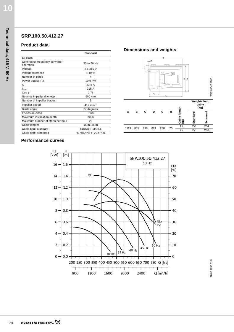
Tec
hn
ica
l da
ta, 4
15
V, 5
0 H
z
70
10
SRP.100.50.412.27
Product dataDimensions and weights
Performance curves
Standard
Ex class
Continuous frequency converter operation
30 to 50 Hz
Voltage 3 x 415 V
Voltage tolerance ± 10 %
Number of poles 4
Power output, P2 10.0 kW
IN 22.5 A
Istart 215 A
Cos 0.76
Nominal impeller diameter 500 mm
Number of impeller blades 3
Impeller speed 412 min-1
Blade angle 27 degrees
Enclosure class IP68
Maximum installation depth 20 m
Maximum number of starts per hour 20
Cable lengths 15 m, 25 m
Cable type, standard S1BN8-F 11G2.5
Cable type, screened H07RC4N8-F 7G4+4x1
TM
03
05
47
02
05
A B C D G H
Ca
ble
le
ng
th[m
]
Weights incl. cable[kg]
Sta
nd
ard
Sc
ree
ne
d
1119 855 996 824 230 2515 253 254
25 258 260
AH
CG
BD
TM
02
98
50
51
04
200 250 300 350 400 450 500 550 600 650 700 750 Q [l/s]
0.0
0.2
0.4
0.6
0.8
1.0
1.2
1.4
1.6
[m]H
800 1200 1600 2000 2400 Q [m³/h]
0
10
20
30
40
50
60
70
[%]Eta
SRP.100.50.412.2750 Hz
Eta
QH
45 Hz40 Hz
35 Hz30 Hz
P2
50 Hz
200 250 300 350 400 450 500 550 600 650 700 750 Q [l/s]
0
2
4
6
8
10
12
14
16
[kW]P2

Tec
hn
ica
l d
ata
, 4
15
V,
50
Hz
10
SRP.70.80.263.11
Product dataDimensions and weights
Performance curves
Standard
Ex class
Continuous frequency converter operation
30 to 50 Hz
Voltage 3 x 415 V
Voltage tolerance ± 10 %
Number of poles 4
Power output, P2 7.0 kW
IN 17.2 A
Istart 165 A
Cos 0.75
Nominal impeller diameter 800 mm
Number of impeller blades 3
Impeller speed 263 min-1
Blade angle 11 degrees
Enclosure class IP68
Maximum installation depth 20 m
Maximum number of starts per hour 20
Cable lengths 15 m, 25 m
Cable type, standard S1BN8-F 11G2.5
Cable type, screened H07RC4N8-F 7G4+4x1
TM
03
05
47
02
05
A B C D G H
Ca
ble
le
ng
th[m
]
Weights incl. cable[kg]
Sta
nd
ard
Sc
ree
ne
d
1129 1237 1006 1225 267 2515 353 354
25 358 360
AH
CG
BD
TM
02
98
51
51
04
100 200 300 400 500 600 700 800 Q [l/s]
0.0
0.1
0.2
0.3
0.4
0.5
0.6
0.7
0.8
0.9
[m]H
500 1000 1500 2000 2500 3000Q [m³/h]
0
10
20
30
40
50
60
70
[%]Eta
SRP.70.80.263.1150 Hz
Eta
QH
45 Hz
40 Hz
35 Hz
30 HzP2
50 Hz
100 200 300 400 500 600 700 800 Q [l/s]
0
1
2
3
4
5
6
7
8
9
[kW]P2
71

Tec
hn
ica
l da
ta, 4
15
V, 5
0 H
z
72
10
SRP.100.80.303.11
Product dataDimensions and weights
Performance curves
Standard
Ex class
Continuous frequency converter operation
30 to 50 Hz
Voltage 3 x 415 V
Voltage tolerance ± 10 %
Number of poles 4
Power output, P2 10.0 kW
IN 22.5 A
Istart 215 A
Cos 0.76
Nominal impeller diameter 800 mm
Number of impeller blades 3
Impeller speed 303 min-1
Blade angle 11 degrees
Enclosure class IP68
Maximum installation depth 20 m
Maximum number of starts per hour 20
Cable lengths 15 m, 25 m
Cable type, standard S1BN8-F 11G2.5
Cable type, screened H07RC4N8-F 7G4+4x1
TM
03
05
47
02
05
A B C D G H
Ca
ble
le
ng
th[m
]
Weights incl. cable[kg]
Sta
nd
ard
Sc
ree
ne
d
1129 1237 1006 1225 267 2515 363 364
25 368 370
AH
CG
BD
TM
02
98
52
51
04
100 200 300 400 500 600 700 800 900 1000 Q [l/s]
0.0
0.1
0.2
0.3
0.4
0.5
0.6
0.7
0.8
0.9
1.0
1.1
1.2
1.3
[m]H
500 1000 1500 2000 2500 3000 3500 Q [m³/h]
0
10
20
30
40
50
60
70
[%]Eta
SRP.100.80.303.1150 Hz
Eta
QH
45 Hz
40 Hz
35 Hz
30 HzP2
50 Hz
100 200 300 400 500 600 700 800 900 1000 Q [l/s]
0
1
2
3
4
5
6
7
8
9
10
11
12
13
[kW]P2

Tec
hn
ica
l d
ata
, 4
15
V,
50
Hz
10
SRP.120.80.323.11
Product dataDimensions and weights
Performance curves
Standard
Ex class
Continuous frequency converter operation
30 to 50 Hz
Voltage 3 x 415 V
Voltage tolerance ± 10 %
Number of poles 4
Power output, P2 12.0 kW
IN 29.3 A
Istart 252 A
Cos 0.68
Nominal impeller diameter 800 mm
Number of impeller blades 3
Impeller speed 323 min-1
Blade angle 11 degrees
Enclosure class IP68
Maximum installation depth 20 m
Maximum number of starts per hour 20
Cable lengths 15 m, 25 m
Cable type, standard H07RN-F 7G4+4x1
Cable type, screened H07RC4N8-F 7G4+4x1
TM
03
05
47
02
05
A B C D G H
Ca
ble
le
ng
th[m
]
Weights incl. cable[kg]
Sta
nd
ard
Sc
ree
ne
d
1181 1257 1058 1225 267 2515 408 409
25 413 415
AH
CG
BD
TM
02
98
53
51
04
150 200 250 300 350 400 450 500 550 600 Q [l/s]
0.0
0.1
0.2
0.3
0.4
0.5
0.6
0.7
0.8
0.9
1.0
1.1
1.2
1.3
1.4
1.5[m]H
600 800 1000 1200 1400 1600 1800 2000 Q [m³/h]
0
5
10
15
20
25
30
35
40
45
50
55
60
65
[%]Eta
SRP.120.80.323.1150 Hz
Eta
QH
45 Hz
40 Hz
35 Hz
30 HzP2
50 Hz
150 200 250 300 350 400 450 500 550 600 Q [l/s]
0
2
4
6
8
10
12
14
16
18
20
22
24
26
28
30[kW]P2
73

Tec
hn
ica
l da
ta, 4
15
V, 5
0 H
z
74
10
SRP.130.80.340.11
Product dataDimensions and weights
Performance curves
Standard
Ex class
Continuous frequency converter operation
30 to 50 Hz
Voltage 3 x 415 V
Voltage tolerance ± 10 %
Number of poles 4
Power output, P2 13.0 kW
IN 27 A
Istart 215 A
Cos 0.82
Nominal impeller diameter 800 mm
Number of impeller blades 3
Impeller speed 340 min-1
Blade angle 11 degrees
Enclosure class IP68
Maximum installation depth 20 m
Maximum number of starts per hour 20
Cable lengths 15 m, 25 m
Cable type, standard S1BN8-F 11G2.5
Cable type, screened H07RC4N8-F 7G4+4x1
TM
03
05
47
02
05
A B C D G H
Ca
ble
le
ng
th[m
]
Weights incl. cable[kg]
Sta
nd
ard
Sc
ree
ne
d
1129 1237 1006 1225 267 2515 363 364
25 368 370
AH
CG
BD
TM
02
98
54
51
04
200 300 400 500 600 700 800 900 1000 1100 Q [l/s]
0.0
0.1
0.2
0.3
0.4
0.5
0.6
0.7
0.8
0.9
1.0
1.1
1.2
1.3
1.4
1.5[m]H
1000 1500 2000 2500 3000 3500 Q [m³/h]
0
5
10
15
20
25
30
35
40
45
50
55
60
65
[%]Eta
SRP.130.80.340.1150 Hz
Eta
QH
45 Hz
40 Hz
35 Hz
30 Hz
P2
50 Hz
200 300 400 500 600 700 800 900 1000 1100 Q [l/s]
0
2
4
6
8
10
12
14
16
18
20
22
24
26
28
30[kW]P2

Tec
hn
ica
l d
ata
, 4
15
V,
50
Hz
10
SRP.160.80.355.11
Product dataDimensions and weights
Performance curves
Standard
Ex class
Continuous frequency converter operation
30 to 50 Hz
Voltage 3 x 415 V
Voltage tolerance ± 10 %
Number of poles 4
Power output, P2 16.0 kW
IN 34.9 A
Istart 252 A
Cos 0.75
Nominal impeller diameter 800 mm
Number of impeller blades 3
Impeller speed 355 min-1
Blade angle 11 degrees
Enclosure class IP68
Maximum installation depth 20 m
Maximum number of starts per hour 20
Cable lengths 15 m, 25 m
Cable type, standard H07RN-F 7G4+4x1
Cable type, screened H07RC4N8-F 7G4+4x1
TM
03
05
47
02
05
A B C D G H
Ca
ble
le
ng
th[m
]
Weights incl. cable[kg]
Sta
nd
ard
Sc
ree
ne
d
1181 1257 1058 1225 267 2515 408 409
25 413 415
AH
CG
BD
TM
02
98
55
51
04
200 300 400 500 600 700 800 900 Q [l/s]
0.0
0.2
0.4
0.6
0.8
1.0
1.2
1.4
1.6
1.8
[m]H
1000 1500 2000 2500 3000 Q [m³/h]
0
10
20
30
40
50
60
70
[%]Eta
SRP.160.80.355.1150 Hz
Eta
QH
45 Hz
40 Hz
35 Hz
30 Hz
P2
50 Hz
200 300 400 500 600 700 800 900 Q [l/s]
0
2
4
6
8
10
12
14
16
18
[kW]P2
75

Tec
hn
ica
l da
ta, 4
15
V, 5
0 H
z
76
10
SRP.130.80.375.11
Product data Dimensions and weights
All dimensions are in mm.
Performance curves
Standard
Ex class
Continuous frequency converter operation
30 to 50 Hz
Voltage 3 x 415 V
Voltage tolerance ± 10 %
Number of poles 4
Power output, P2 13.0 kW
IN 27 A
Istart 215 A
Cos 0.82
Nominal impeller diameter 800 mm
Number of impeller blades 3
Impeller speed 375 min-1
Blade angle 11 degrees
Enclosure class IP68
Maximum installation depth 20 m
Maximum number of starts per hour 20
Cable lengths 15 m, 25 m
Cable type, standard S1BN8-F 11G2.5
Cable type, screened H07RC4N8-F 7G4+4x1
TM
03
05
47
02
05
A B C D G H
Ca
ble
le
ng
th[m
]
Weights incl. cable[kg]
Sta
nd
ard
Sc
ree
ne
d
1129 1237 1006 1225 267 2515 363 364
25 368 370
AH
CG
BD
TM
02
98
56
51
04
500 600 700 800 900 1000 1100 1200 Q [l/s]
0.0
0.1
0.2
0.3
0.4
0.5
0.6
0.7
0.8
0.9
1.0
[m]H
2000 2500 3000 3500 4000 Q [m³/h]
0
10
20
30
40
50
60
70
[%]Eta
SRP.130.80.375.1150 Hz
Eta
QH
45 Hz40 Hz35 Hz30 Hz
P2
50 Hz
500 600 700 800 900 1000 1100 1200 Q [l/s]
0
2
4
6
8
10
12
14
16
18
20
[kW]P2

Tec
hn
ica
l d
ata
, 4
15
V,
50
Hz
10
SRP.200.80.388.11
Product dataDimensions and weights
Performance curves169
Standard
Ex class
Continuous frequency converter operation
30 to 50 Hz
Voltage 3 x 415 V
Voltage tolerance ± 10 %
Number of poles 4
Power output, P2 20.0 kW
IN 45.5 A
Istart 384 A
Cos 0.74
Nominal impeller diameter 800 mm
Number of impeller blades 3
Impeller speed 388 min-1
Blade angle 11 degrees
Enclosure class IP68
Maximum installation depth 20 m
Maximum number of starts per hour 20
Cable lengths 15 m, 25 m
Cable type, standard H07RN-F 7G4+4x1
Cable type, screened H07RC4N8-F 7G4+4x1
TM
03
05
47
02
05
A B C D G H
Ca
ble
le
ng
th[m
]
Weights incl. cable[kg]
Sta
nd
ard
Sc
ree
ne
d
1181 1257 1058 1225 267 2515 433 434
25 438 440
AH
CG
BD
TM
02
98
57
51
04
200 250 300 350 400 450 500 550 600 650 Q [l/s]
0.0
0.2
0.4
0.6
0.8
1.0
1.2
1.4
1.6
1.8
2.0
2.2
[m]H
800 1200 1600 2000 Q [m³/h]
0
10
20
30
40
50
60
70
[%]Eta
SRP.200.80.388.1150 Hz
Eta
QH
45 Hz
40 Hz
35 Hz
30 Hz
P2
50 Hz
200 250 300 350 400 450 500 550 600 650 Q [l/s]
0
4
8
12
16
20
24
28
32
36
40
44
[kW]P2
77

Tec
hn
ica
l da
ta, 4
15
V, 5
0 H
z
78
10
SRP.180.80.387.11
Product dataDimensions and weights
Performance curves
Standard
Ex class
Continuous frequency converter operation
30 to 50 Hz
Voltage 3 x 415 V
Voltage tolerance ± 10 %
Number of poles 4
Power output, P2 18.0 kW
IN 37.5 A
Istart 252 A
Cos 0.78
Nominal impeller diameter 800 mm
Number of impeller blades 3
Impeller speed 387 min-1
Blade angle 11 degrees
Enclosure class IP68
Maximum installation depth 20 m
Maximum number of starts per hour 20
Cable lengths 15 m, 25 m
Cable type, standard H07RN-F 7G4+4x1
Cable type, screened H07RC4N8-F 7G4+4x1
TM
03
05
47
02
05
A B C D G H
Ca
ble
le
ng
th[m
]
Weights incl. cable[kg]
Sta
nd
ard
Sc
ree
ne
d
1181 1257 1058 1225 267 2515 408 409
25 413 415
AH
CG
BD
TM
02
98
58
51
04
300 400 500 600 700 800 900 10001100 1200 Q [l/s]
0.0
0.2
0.4
0.6
0.8
1.0
1.2
1.4
1.6
[m]H
1500 2000 2500 3000 3500 4000 Q [m³/h]
0
10
20
30
40
50
60
70
[%]Eta
SRP.180.80.387.1150 Hz
Eta
QH
45 Hz
40 Hz
35 Hz
30 Hz
P2
50 Hz
300 400 500 600 700 800 900 10001100 1200 Q [l/s]
0
4
8
12
16
20
24
28
32
[kW]P2

Tec
hn
ica
l d
ata
, 4
15
V,
50
Hz
10
SRP.240.80.417.11
Product dataDimensions and weights
Performance curves
Standard
Ex class
Continuous frequency converter operation
30 to 50 Hz
Voltage 3 x 415 V
Voltage tolerance ± 10 %
Number of poles 4
Power output, P2 24.0 kW
IN 49.5 A
Istart 384 A
Cos 0.78
Nominal impeller diameter 800 mm
Number of impeller blades 3
Impeller speed 417 min-1
Blade angle 11 degrees
Enclosure class IP68
Maximum installation depth 20 m
Maximum number of starts per hour 20
Cable lengths 15 m, 25 m
Cable type, standard H07RN-F 7G4+4x1
Cable type, screened H07RC4N8-F 7G4+4x1
TM
03
05
47
02
05
A B C D G H
Ca
ble
le
ng
th[m
]
Weights incl. cable[kg]
Sta
nd
ard
Sc
ree
ne
d
1181 1257 1058 1225 267 2515 433 434
25 438 440
AH
CG
BD
TM
02
98
59
51
04
200 300 400 500 600 700 800 900 1000 Q [l/s]
0.0
0.2
0.4
0.6
0.8
1.0
1.2
1.4
1.6
1.8
2.0
2.2
[m]H
1000 1500 2000 2500 3000 3500 Q [m³/h]
0
10
20
30
40
50
60
70
[%]Eta
SRP.240.80.417.1150 Hz
Eta
QH
45 Hz
40 Hz
35 Hz
30 HzP2
50 Hz
200 300 400 500 600 700 800 900 1000 Q [l/s]
0
4
8
12
16
20
24
28
32
36
40
44
[kW]P2
79

Tec
hn
ica
l da
ta, 4
15
V, 5
0 H
z
80
10
SRP.180.80.417.11
Product dataDimensions and weights
Performance curves
Standard
Ex class
Continuous frequency converter operation
30 to 50 Hz
Voltage 3 x 415 V
Voltage tolerance ± 10 %
Number of poles 4
Power output, P2 18.0 kW
IN 37.5 A
Istart 252 A
Cos 0.78
Nominal impeller diameter 800 mm
Number of impeller blades 3
Impeller speed 417 min-1
Blade angle 11 degrees
Enclosure class IP68
Maximum installation depth 20 m
Maximum number of starts per hour 20
Cable lengths 15 m, 25 m
Cable type, standard H07RN-F 7G4+4x1
Cable type, screened H07RC4N8-F 7G4+4x1
TM
03
05
47
02
05
A B C D G H
Ca
ble
le
ng
th[m
]
Weights incl. cable[kg]
Sta
nd
ard
Sc
ree
ne
d
1181 1257 1058 1225 267 2515 408 409
25 413 415
AH
CG
BD
TM
02
98
60
51
04
500 600 700 800 900 1000 110012001300 1400 Q [l/s]
0.0
0.1
0.2
0.3
0.4
0.5
0.6
0.7
0.8
0.9
1.0
1.1
[m]H
2000 2500 3000 3500 4000 4500 5000 Q [m³/h]
0
10
20
30
40
50
60
70
[%]Eta
SRP.180.80.417.1150 Hz
Eta
QH
45 Hz
40 Hz
35 Hz
30 Hz
P2
50 Hz
500 600 700 800 900 1000 110012001300 1400 Q [l/s]
0
4
8
12
16
20
24
28
32
36
40
44
[kW]P2

Ac
ce
ss
ori
es
Submersible recirculation pumps 11
11. Accessories
Grundfos offers the following equipment for installation, inspection and service of submersible recirculation pumps.
The position numbers in fig. 37 refer to the List of accessories.
Fig. 37 SRP installation drawing
TM
04
39
62
05
09
13
5
17
15
23
1
1
2
19
12
18
81

Ac
ce
ss
orie
s
82
Submersible recirculation pumps11
Selection guide for accessories
List of accessoriesThe position numbers refer to fig. 37.
Products Column profile1) Crane type Wire size Cable clamp type
SRP.xx.30 60 x 60 x 3 M D6 mm D17
SRP.35.50 - SRP.50.50 60 x 60 x 3 M D6 mm D17
SRP.65.50 - SRP.100.50 60 x 60 x 3 L D7 mm D20
SRP.xx.80 60 x 60 x 3 L D7 mm D20
1) If the installation height exceeds 6 m, use an intermediate fixation bracket. If this is not possible, please contact Grundfos.
Drawing Pos. ItemMaterial
DIN W.-Nr./AISIProduct number
1 Bottom fixation for SRP.xx.30.xxx and SRP.xx.50.xxx
1.4301/304 96564825
1.4404/316 L 95037581
1 Bottom fixation for SRP.xx.80.xxx
1.4301/304 96585482
1.4404/316 L 95037600
2
Column profile, 60 x 60 x 3 mm, 1 m*
1.4301/304 96489420
1.4404/316 L 96489421
* The product numbers cover 1 m column profile. When ordering, please state the desired length.
Connection piece for column 60 x 60 x 3 mm, 0.20 m
1.4301/304 95037960
1.4404/3116 L 95037962
5 Top fixation bracket complete incl. safety wire, for 60 x 60 mm column profile
1.4301/304 95037090
1.4404/316 L 95037091
Support for top fixation 1.4301/304 95037404

Ac
ce
ss
ori
es
Submersible recirculation pumps 11
12 Crane foot, for 100 kg crane 1.4301/304 95036937
12 Crane foot, for 100 kg crane 1.4404/316 L 95037665
12 Crane foot, for 100 kg craneGalvanised
steel95036948
12 Crane foot, for 250 and 500 kg crane 1.4301/304 95036908
12 Crane foot, for 250 and 500 kg crane 1.4404/316 L 95037685
12 Crane foot, for 250 and 500 kg craneGalvanised
steel95036894
13 Crane with winch 6AF, 100 kg 1.4301/304 95036845
13 Crane with winch 6AF, 100 kg 1.4404/316 L 95037640
13 Crane with winch 6AF, 100 kgGalvanised
steel95036930
13 Crane with winch 8AF, 250 kg 1.4301/304 95036900
13 Crane with winch 8AF, 250 kg 1.4404/316 L 95037670
13 Crane with winch 8AF, 250 kgGalvanised
steel95036874
13 Crane with winch 12AF, 500 kg 1.4301/304 95036950
13 Crane with winch 12AF, 500 kg 1.4404/316 L 95037700
13 Crane with winch 12AF, 500 kgGalvanised
steel95036975
14 Crane foot for vertical installation, for 100 kg crane 1.4301/304 95036979
14 Crane foot for vertical installation, for 100 kg crane 1.4404/316 L 95037695
14 Crane foot for vertical installation, for 100 kg craneGalvanised
steel95036995
14 Crane foot for vertical installation, for 250 and 500 kg crane 1.4301/304 95036980
14 Crane foot for vertical installation, for 250 and 500 kg crane 1.4404/316 L 95037710
14 Crane foot for vertical installation, for 250 and 500 kg craneGalvanised
steel95037000
15
Lifting wire, ∅6, 10 m, easy mounting, incl. ∅8 shackle and wire clamp 1.4404/316 L 95037144
Lifting wire, ∅6, 15 m, easy mounting, incl. ∅8 shackle and wire clamp 1.4404/316 L 95037145
Lifting wire, ∅7, 10 m, easy mounting, incl. ∅10 shackle and wire clamp 1.4404/316 L 95037146
Lifting wire, ∅7, 15 m, easy mounting, incl. ∅10 shackle and wire clamp 1.4404/316 L 95037147
17
Cable clamp, D17 1.4404/316 L 96494352
Cable clamp, D20 1.4404/316 L 96494354
Drawing Pos. ItemMaterial
DIN W.-Nr./AISIProduct number
83

Ac
ce
ss
orie
s
84
Submersible recirculation pumps11
18 Cable sock, incl. shackle, ∅10Synthetic material,
1.4404/316 L95037141
19 Intermediate fixation bracket complete, for all profile sizes longer than 6 m
1.4301/304 95037148
1.4404/316 L 95037149
23
Connection flange, DN 300
1.4301/304 96564826
1.4404/316 L 95011105
Connection flange, DN 500
1.4301/304 96564827
1.4404/316 L 95011106
Connection flange, DN 800
1.4301/304 96564828
1.4404/316 L 95011107
ALR-20/A relay for leak sensor, 230 V 96489569
Anchor bolt, M12 x 160(1 x anchor, 1 x nut, 1 x washer, 1 x spring washer, 1 x glue cartridge)
1.4404/316 L 95036113
Anchor bolt, M16 x 190 (1 x anchor, 1 x nut, 1 x washer, 1 x spring washer, 1 x glue cartridge)
1.4404/316 L 95037179
Vortex shield for SRP.xx.30.1.4301/304 96564832
1.4404/316 L 95037601
Vortex shield for SRP.xx.50.1.4301/304 96564833
1.4404/316 L 95037602
Vortex shield for SRP.xx.80. 1.4301/304 96564834
1.4404/316 L 95037603
Drawing Pos. ItemMaterial
DIN W.-Nr./AISIProduct number
2 10 4 1 3A1 A2
arnold agLecksonden RelaisNetz 230V 50-60Hz P3VA
II (2)G [EEx ib] IIC nur für den Anschluss von Arnold AGLecksonden Typ AL05 Ex
Schaltpunkt Storung
ALR 20/A ExSEV 05 ATEX 0131
12585 7Sonde
Rel.Netz
CH - 6105 SchachenA Grundfos Company

Fu
rth
er
pro
du
ct
info
rma
tio
n
Submersible recirculation pumps 12
12. Further product information
WebCAPS
WebCAPS is a Web-based Computer Aided Product Selection program available on www.grundfos.com.
WebCAPS contains detailed information on more than 220,000 Grundfos products in more than 30 languages.
Information in WebCAPS is divided into six sections:
• Catalogue
• Literature
• Service
• Sizing
• Replacement
• CAD drawings.
Catalogue
Based on fields of application and pump types, this section contains the following:• technical data• curves (QH, Eta, P1, P2, etc.) which can be adapted to the
density and viscosity of the pumped liquid and show the number of pumps in operation
• product photos• dimensional drawings• wiring diagrams• quotation texts, etc.
Literature
This section contains all the latest documents of a given pump, such as• data booklets• installation and operating instructions• service documentation, such as Service kit catalogue and
Service kit instructions• quick guides• product brochures.
Service
This section contains an easy-to-use interactive service catalogue. Here you can find and identify service parts of both existing and discontinued Grundfos pumps.Furthermore, the section contains service videos showing you how to replace service parts.
85

Fu
rthe
r pro
du
ct in
form
atio
n
86
Submersible recirculation pumps12
WinCAPS
Fig. 38 WinCAPS DVD
Sizing
This section is based on different fields of application and installation examples and gives easy step-by-step instructions in how to size a product:• Select the most suitable and efficient pump for your
installation.• Carry out advanced calculations based on energy,
consumption, payback periods, load profiles, life cycle costs, etc.
• Analyse your selected pump via the built-in life cycle cost tool.• Determine the flow velocity in wastewater applications, etc.
Replacement
In this section you find a guide to selecting and comparing replacement data of an installed pump in order to replace the pump with a more efficient Grundfos pump. The section contains replacement data of a wide range of pumps produced by other manufacturers than Grundfos.
Based on an easy step-by-step guide, you can compare Grundfos pumps with the one you have installed on your site. When you have specified the installed pump, the guide will suggest a number of Grundfos pumps which can improve both comfort and efficiency.
CAD drawings
In this section, it is possible to download 2-dimensional (2D) and 3-dimensional (3D) CAD drawings of most Grundfos pumps.
These formats are available in WebCAPS:
2-dimensional drawings:• .dxf, wireframe drawings• .dwg, wireframe drawings.
3-dimensional drawings:• .dwg, wireframe drawings (without surfaces)• .stp, solid drawings (with surfaces)• .eprt, E-drawings.
WinCAPS is a Windows-based Computer Aided Product Selection program containing detailed information on more than 220,000 Grundfos products in more than 30 languages.
The program contains the same features and functions as WebCAPS, but is an ideal solution if no internet connection is available.
WinCAPS is available on DVD and updated once a year.
0 1

Fu
rth
er
pro
du
ct
info
rma
tio
n
Submersible recirculation pumps 12
GO CAPS
Mobile solution for professionals on the GO!
CAPS functionality on the mobile workplace.
Subject to alterations.
87

GRUNDFOS A/S DK-8850 Bjerringbro . DenmarkTelephone: +45 87 50 14 00www.grundfos.com
96870002 0514
ECM: 1135974 Th
e n
am
e G
run
dfo
s, t
he
Gru
nd
fos
log
o,
an
d b
e t
hin
k i
nn
ov
ate
are
re
gis
tere
d t
rad
em
ark
s o
wn
ed
by
Gru
nd
fos
Ho
ldin
g A
/S o
r G
run
dfo
s A
/S,
De
nm
ark
. A
ll ri
gh
ts r
ese
rve
d w
orl
dw
ide
.©
Co
pyr
igh
t G
run
dfo
s H
old
ing
A/S
![Compact ink recirculation system CC1 - Toshiba Tec Top Page...Compact ink recirculation system Example: Mounting of ink recirculation system [CC1] with ink recirculation head Up to](https://img.pdfslide.net/doc/110x75/5f0f72527e708231d4443441/compact-ink-recirculation-system-cc1-toshiba-tec-top-page-compact-ink-recirculation.jpg)