Embed Size (px)
Citation preview
SRS/STD-TR90-89
TELEROBOTIC ON-ORBIT REMOTE
FLUID RESUPPLY SYSTEM
FINAL REPORT
September 17, 1990
PREPARED FOR
Mr. Thomas C. BryanInformation & Electronics Systems LaboratoryGuidance Control and Optical Systems Division
George C. Marshall Space Flight CenterMarshall Space Flight Center, AL 35812
CONTRACT NO.: NAS8-37743
Approved by.Jay H.Director
AerospaceSystems Directorate
ApprovedC. W. MeadSenior Vice PresidentGeneral Manager
TECHNOLOGIES
SYSTEMS TECHNOLOGY DIVISION
990 EXPLORER BLVD. N.W.CUMMINGS RESEARCH PARK WESTHUNTSVILLE, ALABAMA 35806
(2O5)895-7OOO
https://ntrs.nasa.gov/search.jsp?R=19910004161 2018-07-02T02:42:54+00:00Z
FOREWORD
TR90-89
This final report was prepared by SRS Technologies under Contract No. NAS8-37743, entitled
"Telerobotic On-Orbit Remote Fluid Resupply System", for the George C. Marshall Space Flight Center
of the National Aeronautics and Space Administration. The work was administered under the
technical direction of the Information and Electronics Systems Laboratory Guidance Control and
Optical Systems Division with Ms. Pamela Nelson as Project Manager.
This report describes the work performed on the subject contract, during the May 1989 - July 1989
period by the Aerospace Systems Directorate in the SRS Systems Technology Group. The key project
personnel included:
SRS Technologiesv
John D. Carroll
Joseph C. Cody
Paul A. Gierow
Jim Morrison.
_PARTA Inc,
Richard Matthews
United Applied Technologies
Rodney Bradford
Larry Bradford
ii
SECTION
CONTENTS
TR90-89
PAGE
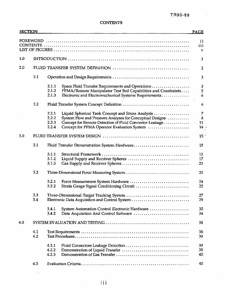
FOREWORD .........................................................................CONTENTS ..........................................................................LIST OF FIGURES .....................................................................
1.0 INTRODUCTION ..............................................................
2.0 FLUID TRANSFER SYSTEM DEFINITION .......................................
2.1 Operation and Design Requirements .......................................
2.1.12.1.22.1.3
Space Fluid Transfer Requirements and OperationsPFMA/Remote Manipulator Test Bed Capabilities and Constraints ....Electronic and Electromechanical Systems Requirements ..............
2.2 Fluid Transfer System Concept Definition ..................................
2.2.12.2.22.2.32.2.4
Liquid Spherical Tank Concept and Stress Analysis ..................System Flow and Pressure Analyses for Conceptual Designs ...........Concept for Remote Detection of Fluid Connector Leakage .............Concept for PFMA Operator Evaluation System .....................
3.0 FLUID TRANSFER SYSTEM DESIGN ............................................
3.1 Fluid Transfer Demonstration System Hardware ............................
3.1.13.1.23.1.3
Structural Framework ............................................
Liquid Supply and Receiver Spheres ...............................Gas Supply and Receiver Spheres ..................................
3.2 Three-Dimensional Force Measuring System ................................
Force Measurement System Hardware ..............................Strain Gauge Signal Conditioning Circuit ...........................
3.33.4
Three-Dimensional Target Tracking System ................................Electronic Data Acquisition and Control System .............................
4.0
3.4,1 System Automation Control Electronic Hardware ....................3.4.2 Data Acquisition And Control Software ............................
SYSTEM EVALUATION AND TESTING ..........................................
4.14.2
Test Requirements .......................................................Test Procedures ..........................................................
4.2.14.2.24.2.3
Fluid Connectors Leakage Detection ................................Demonstration of Liquid Transfer ..................................Demonstration of Gas Transfer .....................................
4.3 Evaluation Criteria ......................................................
iiiii
V
1
2
3
356
6
78
1114 ;-
15
15
151723
23
2425
2729
3O34
38
3839
393940
40
iii
SECTION
CONTENTS
TR90-89
PAGE
5.0
6.0
CONCEPT DEFINITION OF IN-VACUUM TEST BED ..............................
5.1
5.25.3
Facility Interfaces .......................................................In-Vacuum Demonstration System Concept Definition .......................In-Vacuum Fluid Connectors Leak Check ...................................
REFERENCES ..................................................................
APPENDIX A ..................................................................APPENDIX B ..................................................................APPENDIX C ..................................................................
49
494951
52
535569
iv
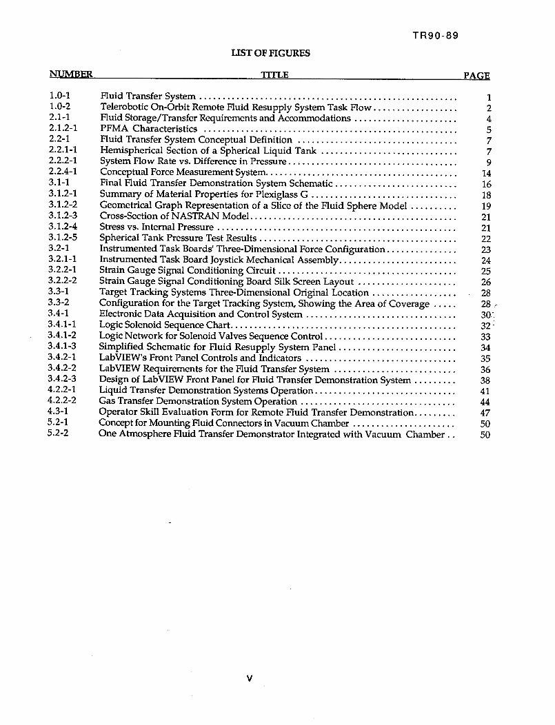
NUMBER
LIST OF FIGURES
TITLE
TR90-89
PAGE
1.0-11.0-2
2.1-1
2.1.2-1
2.2-12.2.1-1
2.2.2-1
2.2.4-1
3.1-1
3.1.2-1
3.1.2-2
3.1.2-3
3.1.2-4
3.1.2-5
3.2-1
3.2.1-13.2.2-1
3.2.2-2
3.3-1
3.3-2
3.4-1
3.4.1-1
3.4.1-2
3.4.1-33.4.2-1
3.4.2-2
3.4.2-3
4.2.2-1
4.2.2-2
4.3-15.2-1
5.2-2
Fluid Transfer System ....................................................... 1
Telerobotic On-Orbit Remote Fluid Resupply System Task Flow .................. 2
Fluid Storage/Transfer Requirements and Accommodations ...................... 4PFMA Characteristics ...................................................... 5
Fluid Transfer System Conceptual Definition .................................. 7
Hemispherical Section of a Spherical Liquid Tank ............................. 7System Flow Rate vs. Difference in Pressure .................................... 9
Conceptual Force Measurement System ......................................... 14
Final Fluid Transfer Demonstration System Schematic .......................... 16
Summary of Material Properties for Plexiglass G ............................... 18
Geometrical Graph Representation of a Slice of the Fluid Sphere Model .......... 19Cross-Section of NASTRAN Model ............................................ 21
Stress vs. Internal Pressure ................................................... 21
Spherical Tank Pressure Test Results .......................................... 22
Instrumented Task Boards' Three-Dimensional Force Configuration ............... 23Instrumented Task Board Joystick Mechanical Assembly ......................... 24
Strain Gauge Signal Conditioning Circuit ...................................... 25
Strain Gauge Signal Conditioning Board Silk Screen Layout ..................... 26
Target Tracking Systems Three-Dimensional Original Location ................... 28
Configuration for the Target Tracking System, Showing the Area of Coverage ..... 28
Electronic Data Acquisition and Control System ................................ 30_
Logic Solenoid Sequence Chart ................................................ 32
Logic Network for Solenoid Valves Sequence Control ............................ 33
Simplified Schematic for Fluid Resupply System Panel ........................ . 34LabVIEW's Front Panel Controls and Indicators ................................ 35
LabVIEW Requirements for the Fluid Transfer System .......................... 36
Design of LabVIEW Front Panel for Fluid Transfer Demonstration System ......... 38Liquid Transfer Demonstration Systems Operation .............................. 41
Gas Transfer Demonstration System Operation ................................. 44Operator Skill Evaluation Form for Remote Fluid Transfer Demonstration ......... 47
Concept for Mounting Fluid Connectors in Vacuum Chamber ...................... 50
One Atmosphere Fluid Transfer Demonstrator Integrated with Vacuum Chamber.. 50
V
1.0 INTRODUCTION
TR90-89
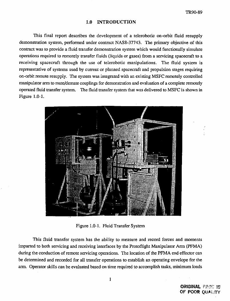
This final report describes the development of a telerobotic on-orbit fluid resupply
demonstration system, performed under contract NAS8-37743. The primary objective of this
contract was to provide a fluid transfer demonstration system which would functionally simulate
operations required to remotely transfer fluids (liquids or gases) from a servicing spacecraft to a
receiving spacecraft through the use of telerobotic manipulations. The fluid system is
representative of systems used by current or planned spacecraft and propulsion stages requiring
on-orbit remote resupply. The system was integrated with an existing MSFC remotely controlled
manipulator arm to mate/demate couplings for demonstration and evaluation of a complete remotely
operated fluid transfer system. The fluid transfer system that was delivered to MSFC is shown in
Figure 1.0-1.
Figure 1.0-1. Fluid Transfer System
This fluid transfer system has the ability to measure and record forces and moments
imparted to both servicing and receiving interfaces by the Protoflight Manipulator Arm (PFMA)
during the conduction of remote servicing operations. The location of the PFMA end effector can
be determined and recorded for all transfer operations to establish an operating envelope for the
arm. Operator skills can be evaluated based on time required to accomplish tasks, minimum loads
ORIGINAL ,_ _
OF POOR QUALITY
TR90-89
generated, the operational envelope required, and the minimizing of operational errors. This data
can be used to evaluate the capability of a telerobotic system in the performance of typical tasks
required for on-orbit fluid transfer.
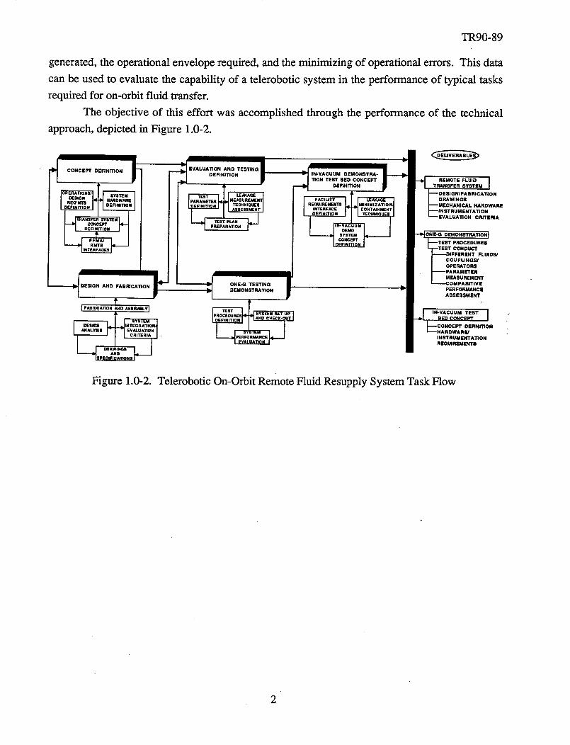
The objective of this effort was accomplished through the performance of the technical
approach, depicted in Figure 1.0-2.
CONCEPT DEFINITION i
-_ DESIGN AND FABRICATION t
t[ F_amCArmN _O ASSSaVaLVl
INTEGI ItTION/IEVALI kTION
RIA
__1
_ EvA,uA,_ONAN*TESTI.G|DEFINITION
ONE-G TESTING
DEMONSTRATION
SYSTEM met UP ]
I
_1 IN-VACUUM DEMONSTRA-
/ _ONTESTsEOCONCEPTI _ .EMOTEFLUID IDE.too. F • t TRANS_E_s*_r_ I
_ f--DESIGN/FABRICATION
" FACILITY DRAWING
REQUIREMENTS _MECHANICAL HARDWARE
INTERFACE _INSTRUMENTATION
--EVALUATION CRITERIA
DEMONSTRA'rlONJ
CONDUCT
FLUIDS/
COU PI.INGS,'
OPERATORS
MEASUREMENT
IITIVE
PERFORMANCE
ASSESSMENT
N
Figure 1.0-2. Telerobotic On-Orbit Remote Fluid Resupply System Task Flow
2.0 FLUID TRANSFER SYSTEM DEFINITION
TR90-89
The following sections describe requirements that governed the operation, design and
concept definition of the Telerobotic On-Orbit Remote Fluid Transfer Demonstration System.
Information regarding space fluid transfer, PFMA test bed capabilities and constraints, and data
acquisition and control requirements were synthesized in order to define the fluid transfer system's
baseline requirements. These baseline requirements were used to develop analytical computer
models for forming the system concept definition and performing analysis of system hardware.
2.1 Operation and Design Requirements
The fluid system is representative of actual systems used by current or planned spacecraft
and space-based propulsion systems and utilizes the existing PFMA/Remote Manipulator Test Bed
(RMTB) at MSFC for demonstrating mating and demating of some specially designed fluid
coupling end effector tools. The system incorporates a means for PFMA operational task
performance evaluation through the measurement of forces and moments imparted on the
instrumented task panel by the PFMA and the tracking of the PFMA's end effector tool used, ;
during fluid transfer operations. The objectives were accomplished by defining and evaluating !
fluid servicing requirements, defining and specifying fluid system hardware requirements
consistentwith PFMA capabilities, and providing specifications, operations and data requirements
to completely define a fluid transfer demonstration system. The information was used to fully
characterize viable on-orbit fluid transfer systems to provide an understanding and data base for
concept definition of a ground-based remotely operated fluid transfer demonstration. Although
primary emphasis was placed on characterizing remotely operated systems, those planned for
manned operation were evaluated for their potential application to remote operations.
2.1.1 Space Fluid Transfer Requirements and Operations
With the recent identification of Space Station Area Traffic Control restrictions, the
importance of Orbital Maneuvering Vehicle (OMV) and Orbit Transfer Vehicle (OTV) operations
has greatly increased. Remote fluid resupply operations in conjunction with these telerobotic space
vehicles will be numerous. In addition to the fluids resupply requirements, the OMV, OTV, and
other upper stage propellant requirements alone show the criticality of this technology in the future.
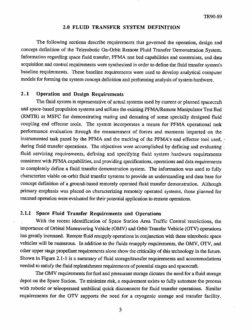
Shown in Figure 2.1-1 is a summary of fluid storage/transfer requirements and accommodations
needed to satisfy the fluid replenishment requirements of potential stages and spacecraft.
The OMV requirements for fuel and pressurant storage dictates the need for a fluid storage
depot on the Space Station. To minimize risk, a requirement exists to fully automate the process
with robotic or teleoperated umbilical quick disconnects for fluid transfer operations. Similar
requirements for the OTV supports the need for a cryogenic storage and transfer facility.
3
TR90-89
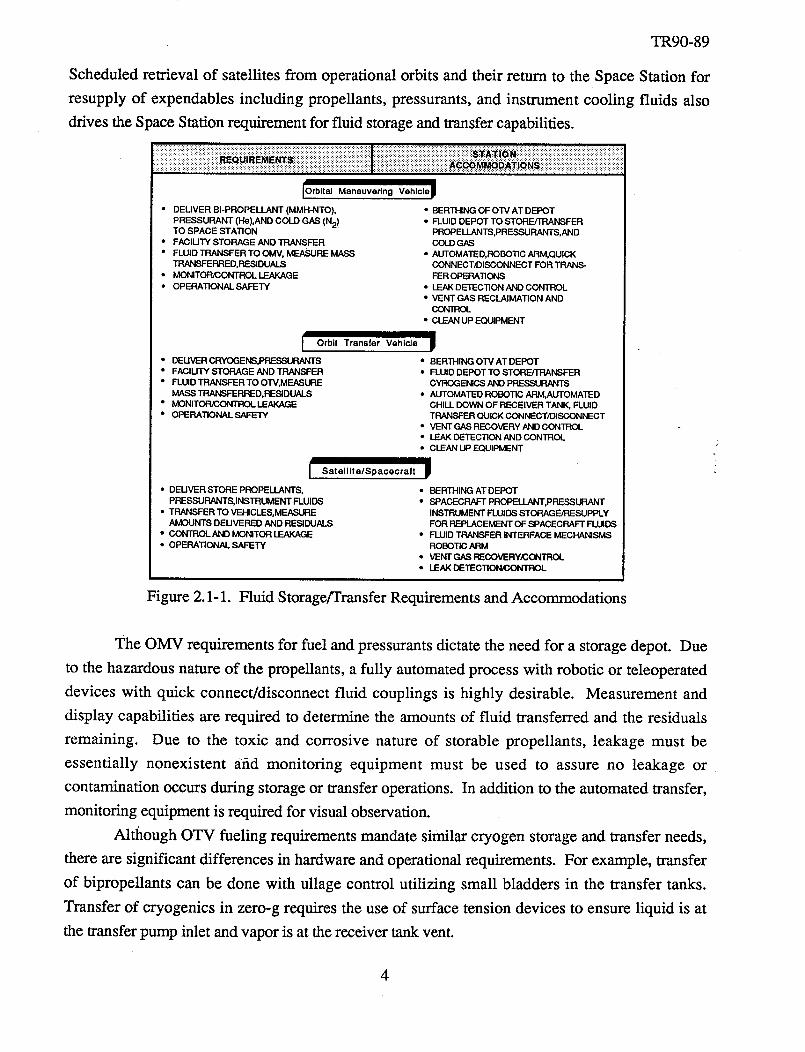
Scheduledretrieval of satellitesfrom operationalorbits and their return to the SpaceStation for
resupply of expendablesincluding propellants,pressurants,and instrument cooling fluids also
drivestheSpaceStationrequirementfor fluid storageandtransfercapabilities.
[Orbital Maneuvering Vehlclep
• DEUVER BI-PROPELLANT (MMH-NTO), • BERTHING OF OTV AT DEPOT
PRESSURANT (He),AND COLD GAS (N2)TO SPACE STATION
• FAClUTY STORAGE AND TRANSFER
• FLUID TRANSFER TO OMV, MEASURE MASSIRANSFERRED, RESIDUALS
• MONITOR/CONTROl_LEAKAGE• OPERATIONAL SAFETY
I Orbit Transfer Vehicle
• DEU VER CRYOG E NS,PRESSt.P,.NqTS• FACIHTY STORAGE AND TRANSFER
• FLUID TRANSFER TO OTV,MEASUREMASS TRANSFERRED,RESIDLIALS
• MONITOR/CONTROL LEAKAGE
• OPERATIONAL SAFETY
I• DEUVER STORE PROPELLANTS,
PRESSURANTS, INSTRUMENT FLUIDS
• TRANSFER TO VEHICLES,MEASUFIEAMOUNTS DEUVERED AND RESIDUALS
• CON/ROLAND MONITOR LEAKAGE
• OPERATIONaL.SAFETY
• FLUID DEPOT TO STORE,qRANSFER
PROPELLANTS,PRESSURANTS, ANDCOLD GAS
• AUTOMATED,ROBOTIC ARM,QUICKCONNECTJOISCONNECT FOR TRANS-FER OPERATIONS
• LEAKDETECTION ANO CONTROL• VENT GAS RECLAIMATION AND
CON'iROL
• CLEAN UP EQUIPMENT
!" BERTHING OTV AT DEPOT" FLUID DEPOT TO STORE/TRANSFER
CYROGENICS AND PRE_S
• AUTOMATED ROBOTIC ARM,AUTOMATEDCHILL DOWN OF RECEIVER TANK, FLUIDTRANSFER QUICK CONNECT/DISCONNECT
• VENT GAS RECOVERY AND CONTROL• LEAK DETECTION AND CONTROL• CLEAN LIPEQUIPMENT
Satellite/Spacecraft p
• BERTHING AT DEPOT
• SPACECRAFT PROPELLANT,PRESSLP, ANTINSTRUMENT FLUIDS STORAGE/RESUPPLYFOR REPLACEMENT OF SPACECRAFT FLUIDS
• FLUID TRANSFER INTERFACE MECHANISMSROBOTIC ARM
• VENT GAS F_-COVERY_OL• LEAK DETECTI_L
Figure 2.1-1. Fluid Storage/Transfer Requirements and Accommodations
The OMV requirements for fuel and pressurants dictate the need for a storage depot. Due
to the hazardous nature of the propellants, a fully automated process with robotic or teleoperated
devices with quick connect/disconnect fluid couplings is highly desirable. Measurement and
display capabilities are required to determine the amounts of fluid transferred and the residuals
remaining. Due to the toxic and corrosive nature of storable propellants, leakage must be
essentially nonexistent arid monitoring equipment must be used to assure no leakage or
contamination occurs during storage or transfer operations. In addition to the automated transfer,
monitoring equipment is required for visual observation.
Although OTV fueling requirements mandate similar cryogen storage and transfer needs,
there are significant differences in hardware and operational requirements. For example, transfer
of bipropellants can be done with ullage control utilizing small bladders in the transfer tanks.
Transfer of cryogenics in zero-g requires the use of surface tension devices to ensure liquid is at
the transfer pump inlet and vapor is at the receiver tank vent.
4
TR90-89
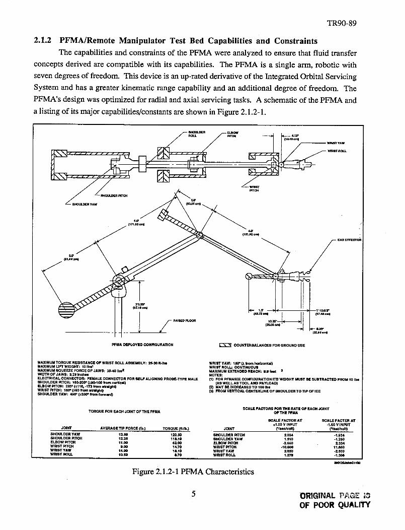
2.1.2 PFMA/Remote Manipulator Test Bed Capabilities and Constraints
The capabilities and constraints of the PFMA were analyzed to ensure that fluid transfer
concepts derived arc compatible with its capabilities. The PFMA is a single arm, robotic with
seven degrees of freedom. This device is an up-rated derivative of the Integrated Orbital Servicing
System and has a greater kinematic range capability and an additional degree of freedom. The
PFMA's design was optimized for radial and axial servicing tasks. A schematic of the PFMA and
a listing of its major capabilities/constants are shown in Figure 2.1.2-1.
4,O'
(lZl&2ornD
END EFFEOTOR
(irt.,Is ore)
I /---PFMA DEPLOYED CONFIGURATION COUNTERBALANCES FOR GROUND USE
MAXIMUM TORQUE RESISTANCE OF WRIST ROLL ASSEMBLY: 25-30 ftJl_
MAXIMUM UFTWBGHT: 10 Ibsl
MAXIMUM SQUEEZE FORCEOF JAWS: 35-40 Ibs 1'WIDTH OF JAWS: 3.25 Inches
ELECTRICAL CONNECTOR: FEMALE CONNECTOR FOR SELF ALIGNING PROBE-TYPE MALE
S_OULDER PITCH: 180-200e (i9_100 fTOm verffcM)
ELBOW PITCH: 2_" (_11_ -173 from strMghtl)
WRIST PITCH: 180" (_-90 fl'om _:alght)
SHOULDER YAW: 400_(¢200" from forwlrd)
TORQUE FOR EACH JOINT OF 11tE PFMA
JOINT AVERAGE TIP FORCE (lb.) TORQUE (ft-lb.)
SHOULDER YAW 12-50 120.50
SHOULDER PITCH 12-23 113.10
ELBOW PITCH 11.00 62.00
WRIST PITCH 9.00 14.70
WRIST YAW 14.00 18,10
WRINT ROLl,. 10.SO L70
WRIST YAW: 180° _ from hodzontM)WRIST ROLL: CONTINUOUS
MAXIMUM EXTENDED REACH: 9.9 feet :s
NOTES:
(1) FOR PFMA/IEE CONFIGURATION ITB WEIGHT MUST BE SUBTRACTED FROM 10 Ibs
(AS WELL AS TOOL AND PAYLOAD)
(2) MAY BE INCREASEDTO 100 Ris
(3) FROM VERTICAL CENTERUNE OF SHOULDER TO TIP OF lEE
JOINT
SCALE FACTORS FOR THE RATE OF EACH JOINTOFTHE PFMA
SCALE FACTOR AT SCALE FACTER AT
+1.00 V INPUT -1.00 1/INPUT
(°/serJvolt) ('/serJvolt)
SHOULDER PITCH 2.034 -1.934
SHOULDER YAW 1.510 -1.280
ELBOW PITCH .2-660 2-334
WRIST PITCH -10.000 11.660
WRIST YAW 2,850 -2.500
WRIST ROLL 1.271 -1.306
Figure 2.1.2-1 PFMA Characteristics
5 ORIGINAL PPoGE i,_
OF POOR QUALWY
TR90-89
2.1.3 Electronic and Electromechanical System Requirements
In order to evaluate the capability of the telerobotic system in the performance of the typical
tasks required for on-orbit fluid transfer, the fluid transfer system incorporates various sensors and
a data acquisition and control system. The electronic/electromechanical system was required to
include a three-dimensional target tracking system, a three-dimensional force and moment
measuring system, and required electronic and electromechanical equipment needed to monitor and
control fluid flow throughout the system.
The three-dimensional target tracking system is used to define the location of the PFMA
end effector in reference to a chosen origin. The three-dimensional force and moment measuring
system was required in order to determine the forces and moments imparted on the instrumented
task boards in which the fluid transfer connectors are mounted, during telerobotic fluid transfer
operations. Actual fluid system tank pressures, transfer rates, transfer times, etc. were evaluated
to estimate the required line sizes, stiffness, lengths, and tanks size/configuration for the fluid
transfer system. Flow rates for the demonstration transfer system are within the flow/pressure loss
capability of the fluid connectors used.
2.2 Fluid Transfer System Concept Definition
This task provided the analysis, design, and systems integration required to develop a
concept definition for a remotely operated fluid transfer system demonstration in one-g. The basic
components and subsystems were defined to provide a viable representation/simulation of a fluid
transfer operation representative of planned propulsion and/or spacecraft on-orbit remote fluid
transfer systems. The results of synthesis and evaluation of requirements and actual system
hardware characterization were utilized in the definition of system design, operations, test, and data
requirements. PFMA/RMTB capabilities and constraints were applied in the concept definition to
assure compatibility with the fluid system definition, available end effectors, and connectors.
In order to eliminate the hazards of transferal of actual propellants and gases used for
powering satellites and various other orbiting vehicles, water was selected as the best
representative fluid for liquid propellant and air was selected as best candidate for the gas
pressurant. Also, a measurement system for determining the three-dimensional forces placed on
the test article and the three-dimensional position of the PFMA end effector relative to the test
article was defined.
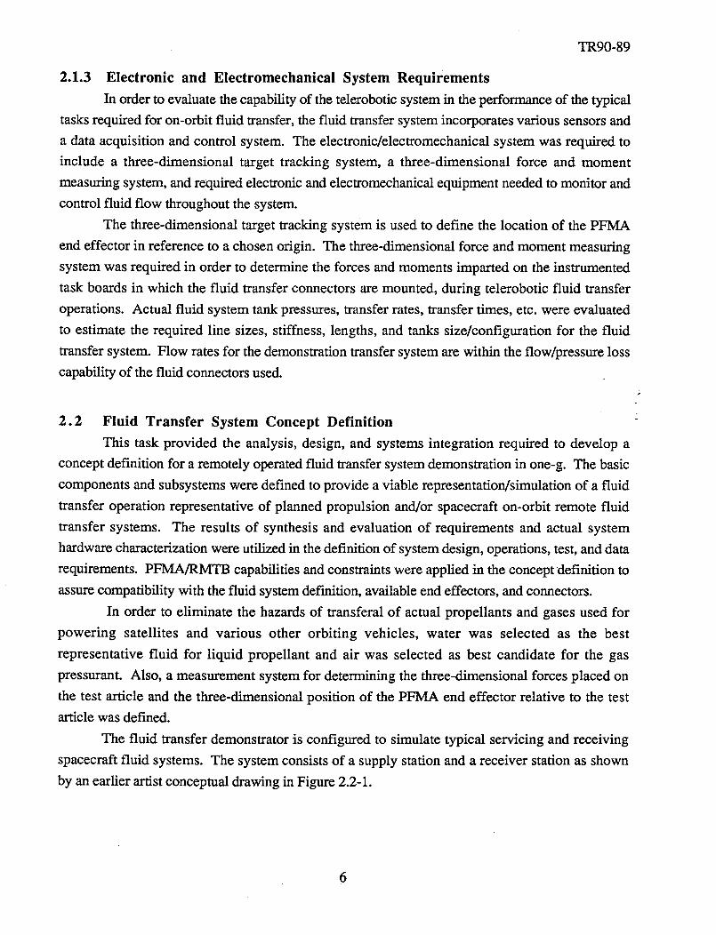
The fluid transfer demonstrator is configured to simulate typical servicing and receiving
spacecraft fluid systems. The system consists of a supply station and a receiver station as shown
by an earlier artist conceptual drawing in Figure 2.2-1.
6
TR90-89
Figure2.2-1. Fluid TransferSystemConceptualDefinition
k
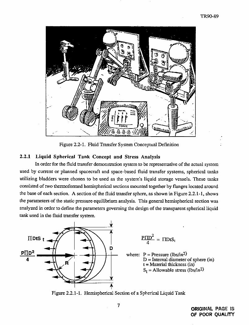
2.2.1 Liquid Spherical Tank Concept and Stress Analysis
In order for the fluid transfer demonstration system to be representative of the actual system
used by current or planned spacecraft and space-based fluid transfer systems, spherical tanks
utilizing bladders were chosen to be used as the system's liquid storage vessels. These tanks
consisted of two thermoformed hemispherical sections mounted together by flanges located around
the base of each section. A section of the fluid transfer sphere, as shown in Figure 2.2.1-1, shows
the parameters of the static pressure equilibrium analysis. This general hemispherical section was
analyzed in order to define the parameters governing the design of the transparent spherical liquid
tank used in the fluid transfer system.
iPI-ID2 = IIDtSt
4
where: P = Pressure (lbs/in 2)
D = Internal diameter of sphere (in)t = Material thickness (in)
S t = Allowable stress (lbs/in 2)
I +Figure 2.2.1-1. Hemispherical Section of a Spherical Liquid Tank
7ORIGINAL PAGE IS
OF POOR QUALITY
TR90-89
The material selected for fluid spheres was clear acrylic because of its transparent property,
for viewing fluid transfer operations, and its good mechanical properties. The spheres were
therrnoformed in two halves with mating flanges. The mechanical properties of acrylics are high
for relatively short-term loading. High stresses can be sustained safely for short periods, since the
relatively low modulus causes a redistribution of stresses. For long-term service, however, tensile
stresses must be limited to avoid crazing or surface cracking.
The computational analysis was based upon a stress level that would insure a factor-of-
safety (FS) of 2. With this FS the material thickness (t) could be sized for operating pressure
levels (P). Design pressure of 10 to 15 psi was specified for the water tanks. A fluid storage of
approximately 5 gallons of water was chosen as the capacity of the storage sphere, to provide one
minutes of transfer time at 5 gal/min. In order to determine the required diameter and wall
thickness, the following equation for the volume of a sphere was used.
V = ¼ I-IR 3 = 1155 in 3 where: V = (5 gallons) (_)gallon
From this equation, the radius of the sphere (R) is 7.9 inches and the diameter (D) of the sphere is -
15.8 inches. A 16 inch diameter spherical tank was chosen for the design due to its availability.
Therefore, with a 16 inch diameter spherical acrylic tank and the allowable stress (St) set at 600 psi
(1500/2.5 [where FS = 2.5]), the wall thickness (t) was calculated from the equation for static
equilibrium, shown in Figure 2.2.1-1, and found to be 0.333 inches.
2.2.2 System Flow and Pressure Analyses for Conceptual Designs
The following analyses provided estimates of transfer flow rates and operating pressures
for the air and water tanks used in the fluid transfer demonstration system. Pressure (flow)
regulators are provided in the lines between the storage and transfer tanks. These pressure
regulators allow the flow and transfer times to be adjusted to the required settings. Flow analyses
provide upper values for operating pressures, and estimates of line pressure losses to assure that
the system will provide a sufficient flow range. The actual transfer time can be adjusted with the
pressure regulator.
The Purolator fluid connector used has a liquid (water) transfer rate of 5 gallons/minute,
which is considered sufficient for a demonstration of fluid transfer. The coupling is sized for a
nominal 1/2 inch fluid line. The fluid transfer line from the fluid supply tank to the fluid receiver
tank is a flexible hose assembly 25 ft. in length with pipe threaded end fittings. The hose is a
general purpose type, rated at 250 psi working pressure and 1000 psi minimum burst pressure.
The hose has a nominal inside diameter of 1/2 inch and an outside diameter of 3/4 inch. The hose
has an inner tube of neoprene, a fiber band over this, and a cover of neoprene overall. Weight of
TR90-89
the hoseis 13 lbs per 100 ft. Hose ends are brass, straight pipe threads (1/2 - 14) with a fluid
passage opening of 0.391 inches.
According to manufacturer's literature, for a 25 ft. length of this hose, at a flow rate of 6
gpm of water, the pressure loss is 8.75 psi. The flow circuit between the fluid supply and storage
tank contains a Purolator connector, hose, and four solenoid valves. The solenoid valve pressure
losses are assumed to be 0.2 velocity head each. The liquid transfer system K factor is calculated
as shown below.
K - AP _ AP
P
The total K factor was calculated as follows:
where: Ke is the K factor for the hoseKv is the K factor for the valves
Kp is the K factor for the Purolator connector ;-
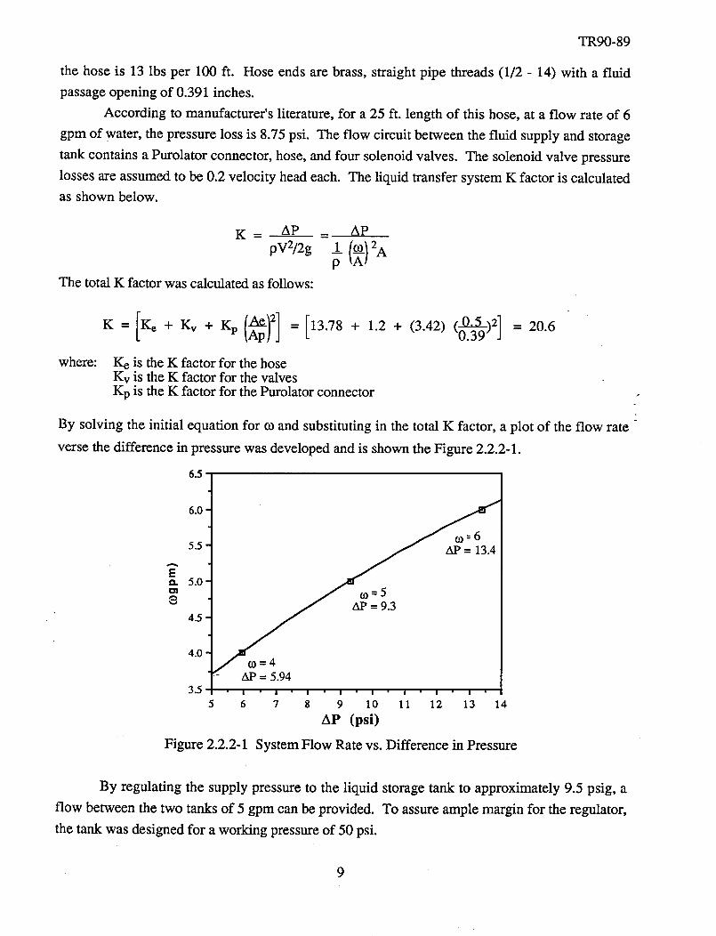
By solving the initial equation for co and substituting in the total K factor, a plot of the flow rate "
verse the difference in pressure was developed and is shown the Figure 2.2.2-1.
6.5
Ee_
6.0 '
5.5
5.0'
4.5
4.0'
3.5
Figure 2.2.2-1
c0--6
(0=5
C0=4- AP = 5.94
• I " ! " | " I I I I i
5 6 7 8 9 10 11 12 13 14
AP (psi)
System Flow Rate vs. Difference in Pressure
By regulating the supply pressure to the liquid storage tank to approximately 9.5 psig, a
flow between the two tanks of 5 gpm can be provided. To assure ample margin for the regulator,
the tank was designed for a working pressure of 50 psi.
.
TR90-89
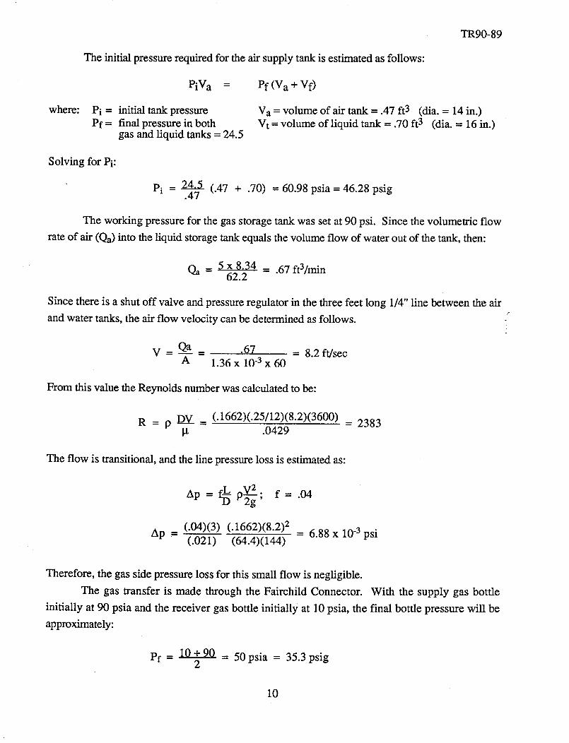
The initial pressure required for the air supply tank is estimated as follows:
PiV a = Pf (V a + Vf)
where: Pi =
Pf=
initial tank pressure
final pressure in bothgas and liquid tanks = 24.5
Va = volume of air tank = .47 ft 3 (dia. = 14 in.)
Vt = volume of liquid tank = .70 ft 3 (dia. = 16 in.)
Solving for Pi:
Pi = 24.5 (.47 + .70) = 60.98 psia = 46.28 psig.47
The working pressure for the gas storage tank was set at 90 psi. Since the volumetric flow
rate of air (Qa) into the liquid storage tank equals the volume flow of water out of the tank, then:
Qa - 5 x 8.34 = .67 ft3/min62.2
Since there is a shut off valve and pressure regulator in the three feet long 1/4" line between the air
and water tanks, the air flow velocity can be determined as follows.
V - Qa _ .67 = 8.2 ft/secA 1.36 x 10 -3 x 60
From this value the Reynolds number was calculated to be:
R = p DV = (.1662)(.25/12)(8.2)(3600) = 2383l.t .0429
The flow is transitional, and the line pressure loss is estimated as:
Ap -
f_ V2"Ap = p-2-_-, f = .04
(.04)(3) (.1662)(8.2) 2 = 6.88 x 10 -3 psi(.021) (54.4)(144)
Therefore, the gas side pressure loss for this small flow is negligible.
The gas transfer is made through the Fairchild Connector. With the supply gas bottle
initially at 90 psia and the receiver gas bottle initially at 10 psia, the final bottle pressure will be
approximately:
pf = 10 +90 = 50psia = 35.3 psig2
10
TR90-89
Thepressureloss for a25 feet, 1/4 inch innerdiameterpipe wascalculatedto be0.15psi,
andthe additionalpressurelossdueto theFairchild valve is small. Consequentlya flow controlvalve in theline allows theflow to besetto thepropervalueto obtaina oneminute transfer. Other
transfertimescanbeobtainedby adjustingthesevalves.
The preliminary designof the liquid tank is shownin Figure B-1, in Appendix B. This
conceptualdesignwasupdateddueto computermodelanalysis,asdescribedlater in the systemdesignsection,andlimitation of availablemanufacturedacrylicsphericaltanks.
2.2.3 Concept for Remote Detection of Fluid Connector Leakage
Prior to initiating an on-orbit fluid transfer operation, it is necessary to verify that the fluid
transfer connectors are capable of accommodating the transfer without excessive leakage. The
concept for verifying the integrity of the remotely operational connectors is described in this
section. The purpose of this system is to identify and quantify leaks that are large enough to
preclude transfer operations. The purpose is not to verify specification leakage for the connectors.
Leaks large enough to preclude transfer are dependent on the fluid to be transferred and the
sensitivity of the surroundings to contamination or other undesirable effects. This system relies on
the measurement of helium leakage and the correlation of this leakage to the leak rate of the fluid !
being transferred. Although the precise relation between helium and transfer fluid leakage must be
determined by testing each connector, an approximation can be made using orifice flow
correlations. Depending on the fluid being transferred, considerable helium may leak before
appreciable transfer fluid leaks. The magnitude of helium leakage that signifies the inception of
transfer fluid leakage was determined by testing each connector with helium and the candidate
transfer fluid. The system described here is to provide a concept demonstration and is not intended
to meet flight requirements specifically in the areas of single point failures, redundancy, etc.
Solenoid valves are used to isolate each connector to allow pressurization of the connectors
with helium. The basic approach is to isolate a volume of helium and measure the pressure decay
to determine the leakage rate. The volume to be isolated contains the connector, line and isolation
values. This volume was determined by the actual measurement of each components volume.
This approach relies on sealing all leak paths except the connector. In a flight system, redundant
isolation valves would be employed to accommodate this, and to eliminate single point failures.
The fluid transfer demonstration system relies on the measurement of helium leakage and
correlation of air and water leak rates with helium leakage. Assuming the leakage through the
connector to be similar to that through an orifice, the mass flow can be related to mass density and
the pressure loss through the orifice.
1) _, = kfpl(P1 - P2)
11
where:
TR90-89
9: fluid densityif: mass flow rate
P: pressure where: (Subscripts 1 & 2 are upstream and downstream conditions.)k: is dependent on the geometry of the leak and to a lesser extent the properties of the
fluid.
Rearranging Equation 1,
2) P1 - P2 = AP -_¢2 _ Pl Q2
K2pl K 2
Using Equation 2 for equivalent pressure loss and k values the volumetric leakage of air can be
related to helium.
3) Qa = f'_[ PH___&QHeV Pa
If both gases are at the same temperature and pressure:
where:
4) Qa A/-M-He QHe-- "V-fiF
MHe = Molecular weight of the helium = 4Ma = Molecular weight of the air = 28.96
Qa = 2_8.96 QHe = 0.372 QHe
Therefore, about three times more helium will leak through an opening than air at equivalent
pressures and temperatures. Since water is an incompressible fluid, and helium is compressible,
the compressibility effects are introduced as follows:
5) @He = K YHe g PIle (P1 - P2)
AP = PIle Q20
(K YHe) 2
where: YHe = Compressibility effect for Helium = 0.8
For water, the change in pressure is
PHzO 2
AP- _-_ QH20
where the compressibility factor for water is 1.
12
TR90-89
Therelationbetweenwaterandheliumleakageis:
f PH_ QHo7) QHzO = "_/
Prig) 0.8¥
For helium at 15 psia and 80°F
8) PIle = 15 x 144 = .01(386.33)(540)
The leakage rate of water compared to helium is therefore:
9) (_-IzO = _ 1 QHe = .0159QHe0.8
The helium leak is about 63 times as great as water for these conditions. This difference in the
leakage rates allowed for f'mer adjustment and calibration of the leakage detection system.
The concept for leak checking the fluid transfer connectors is to pressurize the connector
with low pressure helium in a known volume, monitor the pressure decay rate, and evaluate the
information. Assuming the temperature is constant and the ideal gas law is applicable.
10) w =__V_dPRT dt
where: P, T, V, and R are pressure, temperature, volume, and gas constant, respectively.
R_T °11) fv = pQ = Q
12) Q = v dPP dt
For a constant volumetric leak rate "Q" Equation 12 can be integrated, as shown below.
13) Q = __v_ In V__fAt Pi
The time required to monitor a given leak rate for a given pressure ratio is determined by:
14) Q = _V In PfQ P_
This shows that small volumes and large leaks give the largest pressure differences for a given
time.
For a given leak rate of air or water, helium leaks considerably more. The use of helium
gas has the advantage of reducing the time required for the pressure to decay for a reasonable
pressure measurement. If helium were used with a volume of 3 in 3 and 10% change in pressure
with an air leak of 10 -3 ccs, the observation time would be as follows:
13
TR90-89
At = (4) (2.45) 3 (.372) In (27/30) = 32.25 min60 x 10 -3
The same case for a water leak of 10 -3 ccs would give
At = (3)(2.53) 3 (.021) In (27/30) = 1.82rnin60 x 10 -3
Since the purpose of the remote leak detection system is to detect leaks large enough to
preclude transfer of fluid, and not to verify spec.'s leakage, the time required to detect larger leaks
with this design is considered acceptable.
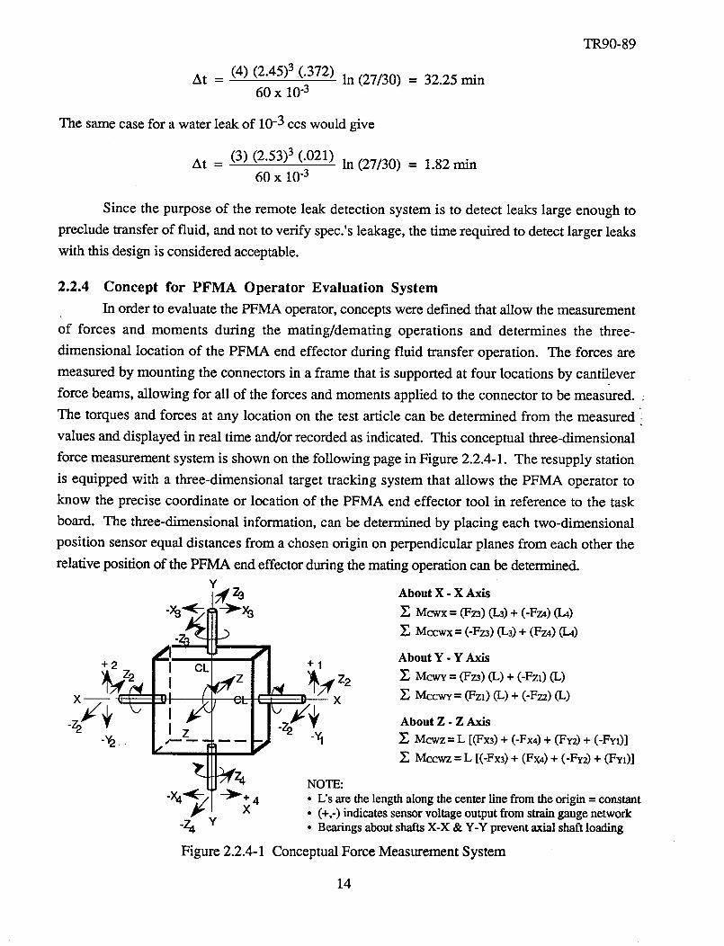
2.2.4 Concept for PFMA Operator Evaluation System
In order to evaluate the PFMA operator, concepts were deemed that allow the measurement
of forces and moments during the mating/demating operations and determines the three-
dimensional location of the PFMA end effector during fluid transfer operation. The forces are
measured by mounting the connectors in a frame that is supported at four locations by cantilever
force beams, allowing for all of the forces and moments applied to the connector to be measured.
The torques and forces at any location on the test article can be determined from the measured
values and displayed in real time and/or recorded as indicated. This conceptual three-dimensional
force measurement system is shown on the following page in Figure 2.2.4-1. The resupply station
is equipped with a three-dimensional target tracking system that allows the PFMA operator to
know the precise coordinate or location of the PFMA end effector tool in reference to the task
board. The three-dimensional information, can be determined by placing each two-dimensional
position sensor equal distances from a chosen origin on perpendicular planes from each other the
relative position of the PFMA end effector during the mating operation can be determined.
Y4Z3
L,"z2 I CL
x r"
,, ?
.)
--_"+ 4X
Y
Figure 2.2.4-1
About X - X Axis
Z Mcwx = (Fz3) (L3) + (-Fz4) (1-4)
Mccwx = (-Fz3) (L3) + (Fz4) (I-4)
About Y - Y Axis
]_ McwY = (Fz3) (L) + (-Fz:) (L)
MccwY = (Fzl) (L) + (-Fza) (L)
About Z - Z Axis
Z Mcwz = L [(Fx3) + (-Fx4) + (Wy2) + (-Fy,)]
Mccwz = L [(-Fx3) + (Fx4) + (-Fy2) + (FYx)]
NOTE:
• L's are the length along the center line from the origin = constant• (+,-) indicates sensor voltage output from swain gauge network• Bearings about shafts X-X & Y-Y prevent axial shaft loading
Conceptual Force Measurement System
14
3.0 FLUID TRANSFER SYSTEM DESIGN
TR90-89
The fluid transfer demonstrator is configured to simulate typical servicing and receiving of
spacecraft fluid systems. The system consists basically of two identical stations: a supply station
and a receiver station. Liquid or gas is transferred from supply to receiver station. In the reverse
mode, the liquid may be transferred bi-directionally from the receiver to the supply tank by
pressurizing the gas receiver tank and valving off the gas supply tank. To facilitate the flow, the
Purolator coupling is used for liquid transfer and the Fairchild connector is used for gas transfer.
Each station will facilitate operation of the coupling (mate/demate) from a square task panel. The
supply station is provided with a Purolator and a Fairchild storage receptacle for storing the male
halves of the coupling devices. The receiver station is provided with both female halves of each
coupling. Both the supply and receiver panels are instrumented to measure forces and torques
exerted upon the panel by the PFMA, through the application of "joy stick" type strain gauge
instrumented beams. These instrumented beams provide an analog output, measuring forces in the
X, Y, Z axis of the panel. Also, a measurement system for determining the three-dimensional
position of the PFMA end effector relative to the test article was designed.
3.1 Fluid Transfer Demonstration System Hardware
The basic items of hardware at each station are a spherical liquid tank, a spherical gas
pressurant tank, an instrumented task panel with coupling storage (or receptacle) devices attached,
flexible fluid and gas transfer lines, and system valves. To provide portability, each station consist
of a structural framework with a soft-mount cradle to support the pressurant and fluid tanks. The
liquid and gas couplings are mounted on a task panel with an outer and inner frame to facilitate the
"joy stick" force sensors, and an A-frame type structure.
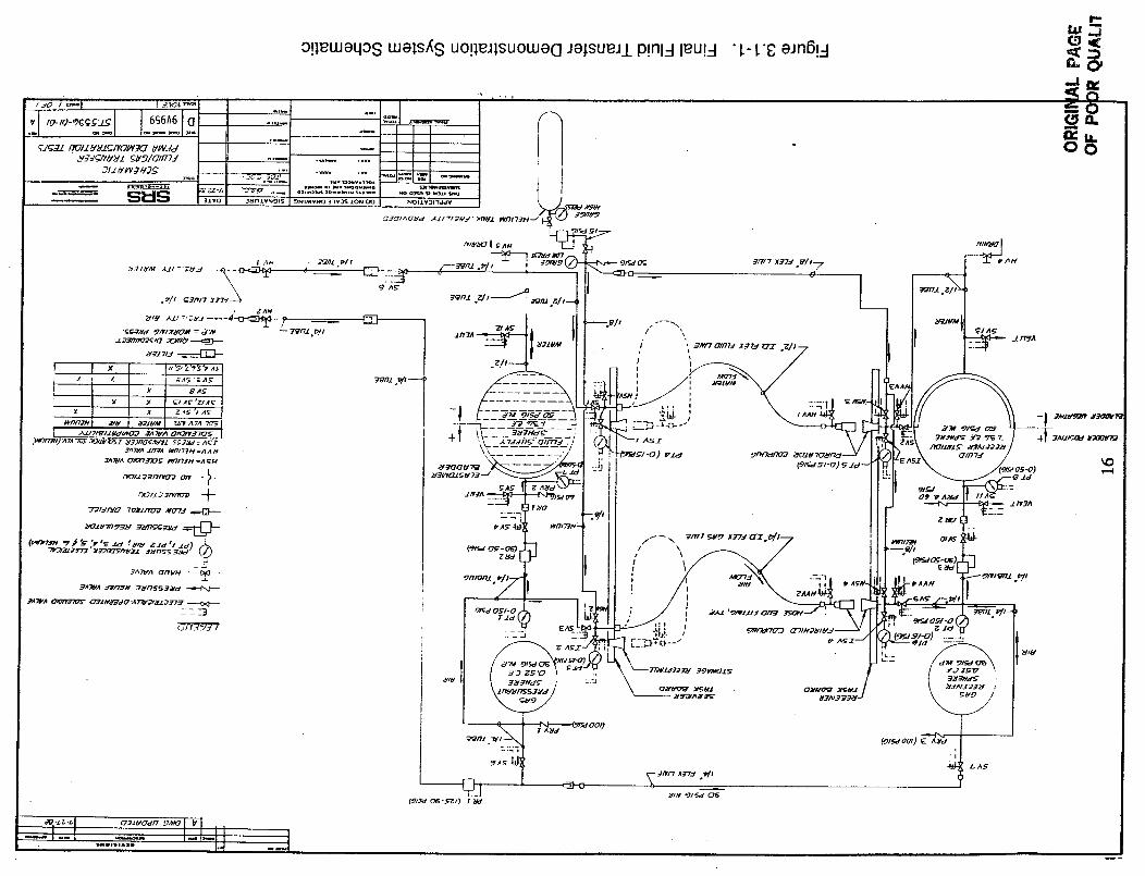
The schematic of the gas and liquid flow circuit for the fluid transfer demonstration system
is shown in Figure 3.1-1. This system provides for the simulation of transfer of both gas and
liquid. A capability for remote leak checking of the fluid connectors in both the demated and mated
configurations is provided. The liquid lines can be remotely purged of liquid after liquid transfer
and prior to storage of the servicer half on the fluid connector.
3.1.1 Structural Framework
The fluid transfer system consists of two free-standing support frameworks, one frame for
the servicer task panel (supply side) and one frame for the receiver task panel (resupply side). The
frameworks are identical in dimensions, but are of opposite hand orientation. Figure B-2, in
Appendix B, is a mechanical assembly drawing (Drawing No. ST5396-01) defining the frame at
the receiver task panel. The structural framework consists of a 1.50 inch square tubular
framework of steel, welded construction, with two valve panels and one electronic equipment
mounting panel bolted to the frame. Not shown on this drawing is the structural cradle support for
15
:1'_'o--o" °_1.'.U_dgJ'VIIY_/ _/.t.91GII77J
21.l _I@_H2_
SI::IS ....
,, o_
_P"_'_ .o _
: _,i-,z-_ _*'o,_n "_,_t v l- -- ...,.=- --l.J--I
o!leLuaqos Luels_s uo!ieJlsuowe(] Ja)tsueJJ. P!nl-I leUL-I "l-l'g eJn6!-!
TR90-89
the gas and fluid spheres. Flexible fluid, gas and helium lines interface the two systems through
either liquid/gas couplings or via quick-disconnects such that each system framework is
independent for portability. Each frame assembly has independent main valve panel assemblies
consisting of pressure regulators, pressure relief valves, pressure transducers, solenoid control
valves, hand valves and quick-disconnect coupling for fluid, gas, and helium supply sources. The
valve sub-panels are located in close proximity of their respective task panel to facilitate the helium
leak check operation.
The receiver task panel is the standard inner and outer frame assemblies with strain gauge
joy-stick load sensors, such as provided previously under contract NAS8-3607, Modification 9,
and described in section 3.2.2. The receiver panel, mounted to the inner frame of the task panel
assembly, contains the Purolator and Fairchild female coupling tool, while the servicer task panel
(same configuration as the receiver task panel) has mounted storage receptacles for both couplers.
To determine the force exerted upon the servicer task panel by the fluid and gas transfer lines, a
bulkhead connector for each line (gas and fluid) was installed on the panel center lines to facilitate
the interface fluid lines connection between the two stations. Storage receptacles are located
immediately above the bulkhead connectors. These instrumented task panel connections for the
supply side are shown in Figure B-3 (Drawing No. ST5396-01-02), in Appendix B.
3.1.2 Liquid Supply and Receiver Spheres
The PFMA fluid transfer system being designed for MSFC contains a clear acrylic
thermoplastic sphere used to hold water with a working pressure of 10 psig. The sphere is made
in two halves and joined with a bolted flange. An elastomer bladder is held in place by the
clamping force between the two halves of the fluid sphere. The sphere has ahole on the top for the
pressurant access and the bottom to allow the transfer water.
The design of the fluid sphere is described in more detail in Figure B-4 (Drawing No.
ST5396-001B, page 1 & 2). This drawing of the acrylic sphere was investigated by computer
aided stress modeling. This design effort was deemed necessary to eliminate inboard loading and
distortion of the sphere at the hemispherical mating flanges, introducing excessive loading that
might be caused by the V-band coupler torque. This third design iteration eliminates the V-band
tightening arrangement and substitutes bolted connections around the mating flanges. At the same
time, the flanges were thickened and are sandwiched between metallic annular rings to provide
good bearing surfaces for the through bolt connections as well as the acrylic substrate. The
spheres were pressure tested to proof pressures >4 x operating pressure to verify their structural
integrity prior to integration into the system.
It is to be noted that for a clear acrylic sphere of this size and pressure requirements, stress
analysis is more complex because this rather flexible material does not behave like standard metallic
pressure vessels, and true stress-strain relationships are unlike metallic materials. Due to the
17
TR90-89
pressurizationof the sphere,a stressanalysiswasneededto ensurethat therewere no principal
stressesto exceedacceptablelimits. Thestressanalysiswasperformedusingthe 1988versionofCOSMIC/NASTRAN. To ensurethat the fluid transfer tank would not be over pressurized,a
pressurerelief valvewasinstalledandsetto 15psig.
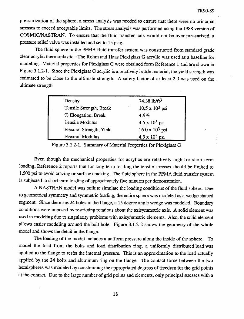
The fluid spherein thePFMA fluid transfersystemwasconstructedfrom standardgradeclear acrylic thermoplastic.-The Rohm andHaasPlexiglassG acrylic wasusedasa baselinefor
modeling. Material propertiesfor PlexiglassG wereobtainedform Reference1andareshownin
Figure 3.1.2-1. SincethePlexiglassG acrylic is arelatively brittle material,theyield strengthwas
estimatedto be close to the ultimate strength. A safety factor of at least2.0 wasused on theultimatestrength.
Density
TensileStrength,Break
% Elongation,BreakTensileModulus
FlexuralStrength,YieldFlexuralModulus
Figure 3.1.2-1.
74.38lb/ft 3
10.5x 10³psi4.9%
4.5x 10⁵psi
16.0x 10³psi
4.5 x 10⁵psi
Summaryof MaterialPropertiesfor PlexiglassG
Even though the mechanicalproperties for acrylics are relatively high for short termloading, Reference2 reports that for long term loading the tensile stressesshouldbe limited to
1,500psi to avoidcrazingor surfacecracking. The fluid spherein thePFMA fluid transfersystem
is subjectedto shorttermloadingof approximatelyfive minutesperdemonstration.
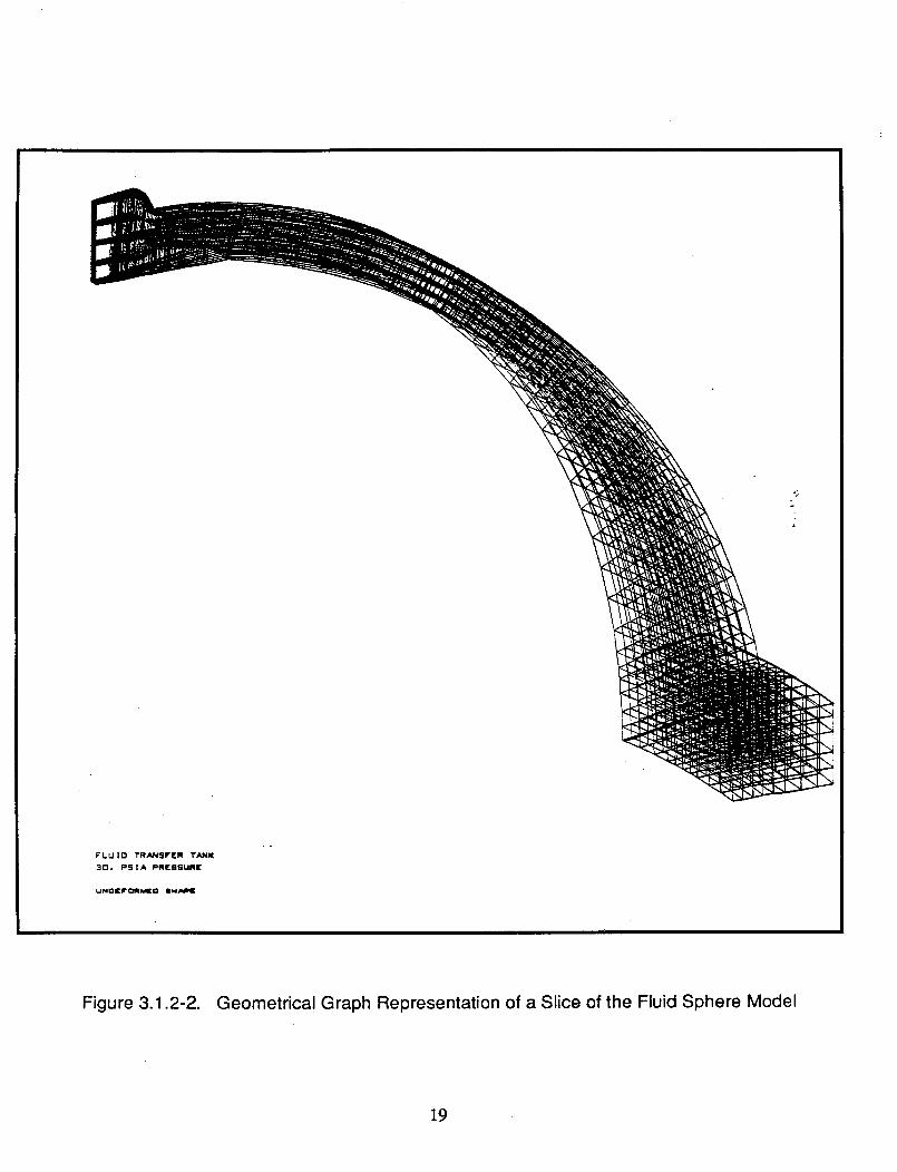
A NASTRAN modelwasbuilt to simulatethe loadingconditionsof thefluid sphere.Due
to geometricalsymmetryandsymmetricloading,theentirespherewasmodeledasawedgeshaped
segment.Sincethereare24holesin theflange,a 15degreeanglewedgewasmodeled.Boundary
conditionswereimposedby restrictingrotationsabouttheaxisymmetricaxis. A solidelementwasusedin modelingdueto singularityproblemswith axisymmetricelements.Also, thesolid element
allows easiermodeling around the bolt hole. Figure 3.1.2-2 showsthe geometryof the wholemodelandshowsthedetailin theflange.
The loading of the model includesa uniform pressurealong theinside of the sphere. To
model the load from the bolts and load distribution ring, a uniformly distributedload was
appliedto the flangeto resist the internalpressure.This is an approximationto the load actually
applied by the 24 bolts and aluminum ring on the flange. The contact force between the two
hemisphereswasmodeledby constrainingtheappropriateddegreesof freedomfor the grid points
at thecontact. Due to thelargenumberof grid points andelements,only principal stresseswith a
18
FI.UIO TRN#SF([R I"AN_
30. PStA PRrssuRK
UNOI_f_N_O S_AImE
Figure 3.1.2-2. Geometrical Graph Representation of a Slice of the Fluid Sphere Model
19
TR90-89
magnitude greater than 1000 psi were used. This allowed a much easier analysis of the locations
of stress concentrations.
The analysis of the fluid sphere is not as straight forward as it might seem because the
Thisequation for the stresses in a thin walled sphere do not hold true near the hole or flange.
equation is as follows:
s = Pr/(2t) (1)
where: s = Principal Stress r = Mean Radius
P = Pressure t = Wall Thickness
The primary area of concern in the fluid sphere is the stress around the flange because the
bending, shearing and normal forces on the flange produce the highest stresses in the fluid sphere.
The stresses in the walls away from the flange or the hole are approximately equal to those
calculated from equation (1). From this equation, the principal stresses in the wall away from the
hole and flange are 255 psi for an internal pressure of 30 psi. For an internal pressure of 70 psi,
the principal stresses in the walls rise to 595 psi. These stresses are well under the ultimate stress
of 10,500 psi.
Because of the complex state of stress around the flange, a finite element model was Used _:
to predict the maximum principal stresses. For an internal pressure of 30 psi, the maximum :
principal stress estimated was 1718 psi. This stress would give a safety factor of 6.11. When the
internal pressure was increased to 70 psi, the maximum estimated principal stress was 5194 psi.
An internal pressure of 70 psi gives a minimum safety factor of 2.02. Since all principal stresses
exceeded a safety factor of 2.0 and the safety factor at the normal operating pressure of 30 psi was
6.11, the fluid sphere meets safety requirements for the system.
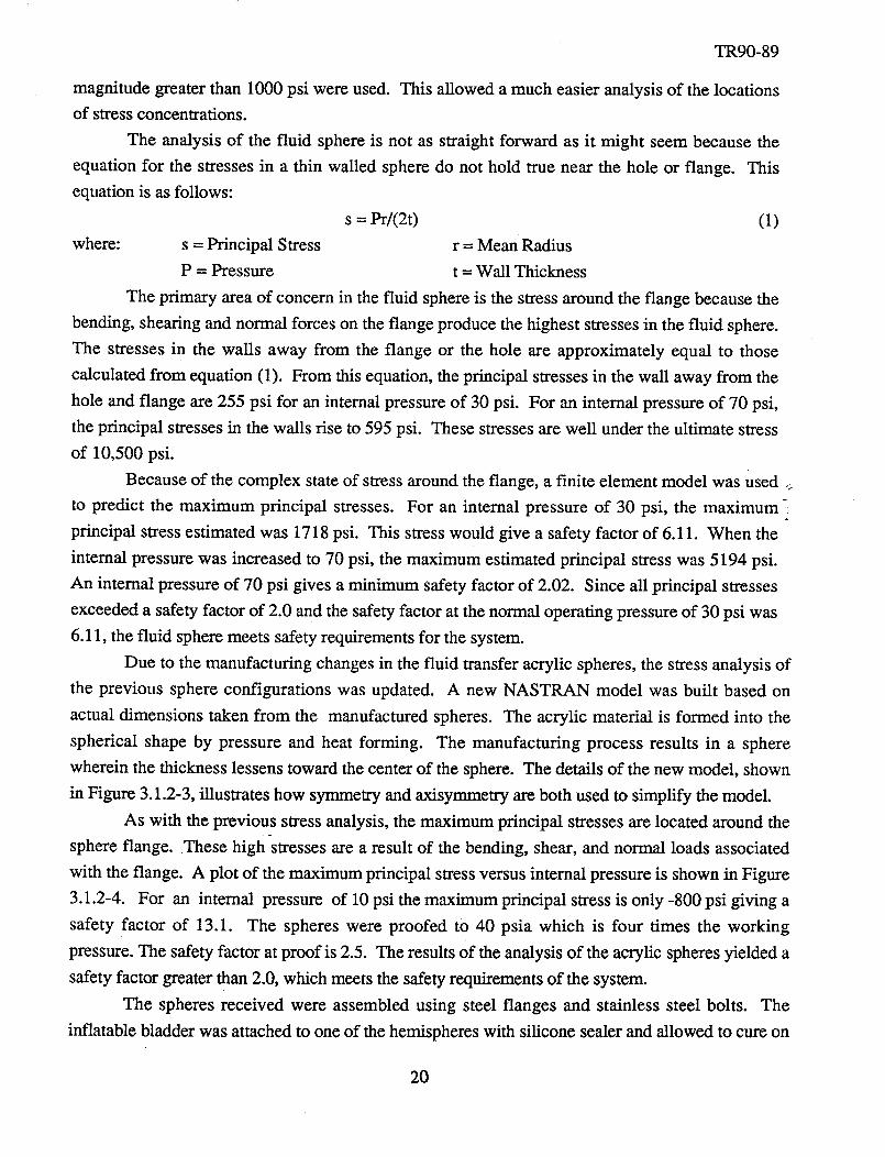
Due to the manufacturing changes in the fluid transfer acrylic spheres, the stress analysis of
the previous sphere configurations was updated. A new NASTRAN model was built based on
actual dimensions taken from the manufactured spheres. The acrylic material is formed into the
spherical shape by pressure and heat forming. The manufacturing process results in a sphere
wherein the thickness lessens toward the center of the sphere. The details of the new model, shown
in Figure 3.1.2-3, illustrates how symmetry and axisymmetry are both used to simplify the model.
As with the previous stress analysis, the maximum principal stresses are located around the
sphere flange. These highstresses are a result of the bending, shear, and normal loads associated
with the flange. A plot of the maximum principal stress versus internal pressure is shown in Figure
3.1.2-4. For an internal pressure of 10 psi the maximum principal stress is only -800 psi giving a
safety factor of 13.1. The spheres were proofed to 40 psia which is four times the working
pressure. The safety factor at proof is 2.5. The results Of the analysis of the acrylic spheres yielded a
safety factor greater than 2.0, which meets the safety requirements of the system.
The spheres received were assembled using steel flanges and stainless steel bolts. The
inflatable bladder was attached to one of the hemispheres with silicone sealer and allowed to cure on
20
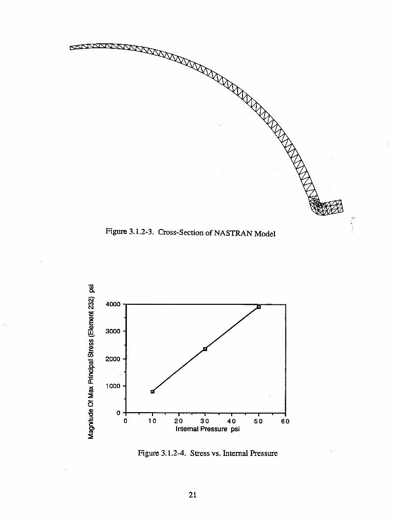
Figure 3.1.2-3. Cross-Section of NASTRAN Model
o.A
t_Od
E
tUv
tt_
t_
t-.t-tl.
O
"O
¢-
t_
4000
3000
2000
. =
1000
0
0I l ' I I ' I
10 20 30 40 50
IntemalPmssure psi
Figure 3.1.2-4. Stress vs. Internal Pressure
60
21
TR90-89
the sphere flange. Following a 24 hour cure time, the other hemisphere was mated to the bladder
and first hemisphere with silicone sealer and stainless steel bolts, with the steel flanges mounted
outside of the acrylic flanges. The spheres were pressure tested using water and a regulated air
pressure. The spheres were initially filled with water and then the regulated air pressurant was
applied to the sphere to provide for a more accurate pressure control. The pressurization procedure
used for the tests are shown below.
1. Fill Tanks with Water
2. Close Water Valve
3. Pressurize to 20 psi with Air as Pressurant
4. Investigate Seals and Bladder for Leaks or Tears
5. Continue Pressurization at 0.5 psi/second until 40 psi is Reached
6. Hold at 40 psi for Three Minutes
7. Inspect for Leaks and Failure
8. Depressurize the Tank
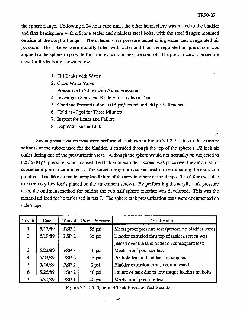
Seven pressurization tests were performed as shown in Figure 3.1.2-5. Due to the extreme
softness of the rubber used for the bladder, it extruded through the top of the sphere's 1/2 inch air
outlet during one of the pressurization test. Although the sphere would not normally be subjected to
the 35-40 psi pressure, which caused the bladder to extrude, a screen was place over the air outlet for
subsequent pressurization tests. The screen design proved successful in eliminating the extrusion
problem. Test #6 resulted in complete failure of the acrylic sphere at the flange. The failure was due
to extremely low loads placed on the attachment screws. By performing the acrylic tank pressure
tests, the optimum method for bolting the two half sphere together was developed. This was the
method utilized for he tank used in test 7. The sphere tank pressurization tests were documented on
video tape.
Test # Date
1 5/17/89
2 5/19/89
3
4
5
6
7
5/22/89
5/23/89
5/24/89
5/26/89
5/30/89
Tank #
PSP 1
PSP 2
Proof Pressure
55 psi
35 psi
PSP 3
PSP 2
PSP 2
PSP 2
PSP 1
Figure 3.1.2-5
40 psi
15 psi
0 psi
40 psi
40 psi
Test Results
Meets proof pressure test (pretest, no bladder used)
Bladder extruded thru top of tank (a screen was
placed over the tank outlet on subsequent test)
Meets proof pressure test
Pin hole leak in bladder, test stopped
Bladder extrusion thru side, not tested
Failure of tank due to low torque loading on bolts
Meets proof pressure test
Spherical Tank Pressure Test Results
22
TR90-89
3.1.3 Gas Supply and Receiver Spheres
The gas transfer spheres selected have a 14 inch diameter, pressurized to 90 psig internal
pressure, storing about 0.81 cubic feet of gas (air). The gas sphere is a vendor-furnished item
fabricated from 304 stainless steel with a wail thickness of 0.083 inch. The sphere has a port on
one end with a one-quarter inch standard pipe threat that interfaces with the system tubing
arrangement. The gas spheres have a pressure rating of 350 psig and were pressure tested and
certified to this pressure at the factory. At 350 psig, a conservative safety factor of 4 x operating
pressure can be expected. A copy of the certification is included in the appendix of this report.
3.2 Three-Dimensional Force Measuring System
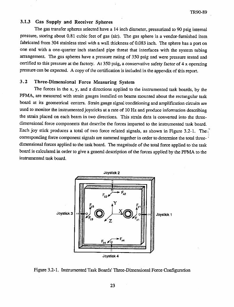
The forces in the x, y, and z directions applied to the instrumented task boards, by the
PFMA, are measured with strain gauges installed on beams mounted about the rectangular task
board at its geometrical centers. Strain gauge signal conditioning and amplification circuits are
used to monitor the instrumented joysticks at a rate of 10 Hz and produce information describing
the strain placed on each beam in two directions. This strain data is converted into the three-
dimensional force components that describe the forces imparted to the instrumented task board.
Each joy stick produces a total of two force related signals, as shown in Figure 3.2-1. The _'_
corresponding force component signals are summed together in order to determine the total three-"
dimensional forces applied to the task board. The magnitude of the total force applied to the task
board is calculated in order to give a general description of the forces applied by the PFMA to the
instrumented task board.
Joystick 3
Joystick 2
Joystick 4
Joystick 1
Figure 3.2-1. Instrumented Task Boards' Three-Dimensional Force Configuration
23
TR90-89
Convertingthe straindatainto forcedataandthecalculationof thethree-dimensionalforce
appliedto thetaskboardis accomplishedthroughuseof aLabVIEW control software.This datais
stored and displayed on the computer monitor in real time graphic plots. This enables thecontroller'soperationsandactionsto bemonitoredandevaluated.
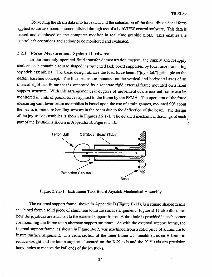
3.2.1 Force Measurement System Hardware
In the remotely operated fluid transfer demonstration system, the supply and resupply
stations each contain a square shaped instrumented task board supported by four force measuring
joy stick assemblies. The basic design utilizes the load force beam ("joy stick") principle as the
design baseline concept. The four beams are mounted on the vertical and horizontal axes of an
internal rigid test frame that is supported by a separate rigid external frame mounted on a fixed
support structure. With this arrangement, six degrees of movement of the internal frame can be
monitored in units of pound forces applied to the frame by the PFMA. The operation of the force
measuring cantilever beam assemblies is based upon the use of strain gauges, mounted 90 ° about
the beam, to measure bending stresses in the beam due to the deflection of the beam. The design
of the joy stick assemblies is shown in Figures 3.2.1-1. The detailed mechanical drawings of each _
part of the joystick is shown in Appendix B, Figures 5-10.
Teflon Ball Cantilever Beam (Tube)
•.:.:.:.:_:.:.:.:.:.:;:;" ..
Protection Canister
Base
Figure 3.2.1-1. Instrument Task Board Joystick Mechanical Assembly
The external support frame, shown in Appendix B (Figure B-11), is a square shaped frame
machined from a solid piece of aluminum to insure surface alignment. Figure B- 11 also illustrates
how the joysticks are attached to the external support frame. A thru hole is provided in each comer
for mounting the frame to an alternate support structure. As with the external support frame, the
internal support frame, as shown in Figure B-12, was machined from a solid piece of aluminum to
insure surface alignment. The cross section of the inner frame was machined as an H-beam to
reduce weight and maintain support. Located on the X-X axis and the Y-Y axis are precision
bored holes to receive the ball ends of the joysticks.
24
TR90-89
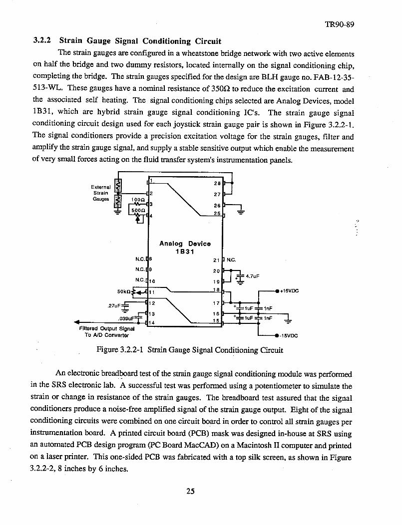
3.2.2 Strain Gauge Signal Conditioning Circuit
The strain gauges are configured in a wheatstone bridge network with two active elements
on half the bridge and two dummy resistors, located internally on the signal conditioning chip,
completing the bridge. The strain gauges specified for the design are BLH gauge no. FAB-12-35-
513-WL. These gauges have a nominal resistance of 350f_ to reduce the excitation current and
the associated self heating. The signal conditioning chips selected are Analog Devices, model
1B31, which are hybrid strain gauge signal conditioning IC's. The strain gauge signal
conditioning circuit design used for each joystick strain gauge pair is shown in Figure 3.2.2-1.
The signal conditioners provide a precision excitation voltage for the strain gauges, filter and
amplify the strain gauge signal, and supply a stable sensitive output which enable the measurement
of very small forces acting on the fluid transfer system's instrumentation panels.
External
Strain
Gauges 100_4
N.C.I
N.C.
N.C.
Filtered Output Signal
To AJD Converter
27
3 26
4
Analog Device1B31
21
9 20
10 19
11 _ 18
12 _ 1713 16
14 15
q+ = ,_ +15VDC- I" luF_lnF
"1- -_.
C
Figure 3.2.2-1 Strain Gauge Signal Conditioning Circuit
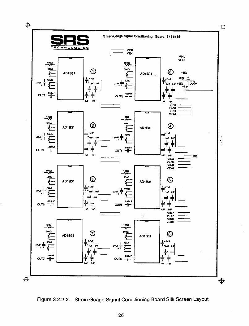
An electronic breadboard test of the strain gauge signal conditioning module was performed
in the SRS electronic lab. A successful test was performed using a potentiometer to simulate the
strain or change in resistance of the strain gauges. The breadboard test assured that the signal
conditioners produce a noise-free amplified signal of the strain gauge output. Eight of the signal
conditioning circuits were combined on one circuit board in order to control all strain gauges per
instrumentation board. A printed circuit board (PCB) mask was designed in-house at SRS using
an automated PCB design program (PC Board MacCAD) on a Macintosh II computer and printed
on a laser printer. This one-sided PCB was fabricated with a top silk screen, as shown in Figure
3.2.2-2, 8 inches by 6 inches.
25
÷ ÷
÷
StrahGauge Si:jnal Condlioning Board 8/16/88
TECHNOLOGIES
1oo0
5OOG
AD1 B31
VIN1
VEX1
100Q
E
T_T+T .03gu F,.F ,_ OUT2 "11"
100Q
S0¢Q
E
.03guF
ouT3 -tl-
AD1 B31
IOOQ
(_) _E-L 4.7uF
_6T]_ T -- .o3*FT T 0UT4 ,-Ira--luF InF
100Q
50_
E
.03guF
ou_ -tl--
AD1B31
10_Q
4,TulF
IT,.L T -- .o3_,FTT OUTS _l--
100Q
50_
10_Q
.L 4.TuF
ITJ.. T -- 0_*.FTT 0UT8 "IPluF tel=
ADIB31
VIN2
VEX2
O -15V
_L,.TuF g_O J"
T-,._ ,._ ÷l__l"__61
h.T1 T --TTIuF lnF
VIN3VEX3
VIN4
VEX4_
®
_6T_L TI --TT
'IuF lnF _VIN5
VEX5VIN6
VEX8
©
_6T/TI --TTI_F INF
VIN7VEX'/VIN8VEXB
©
÷
Figure 3.2.2-2. Strain Guage Signal Conditioning Board Silk Screen Layout
26
TR90-89
3.3 Three-Dimensional Target Tracking System
The resupply station is equipped with a three-dimensional target tracking system that allows
the controller to know the precise coordinates of the PFMA end effector relative to the instrumented
task board. This system is comprised of two Hamamatus (C2399-00) two-dimensional position
sensor systems. The C2399-00 Position Sensor is an opto-electric position sensing unit designed
to take advantage of the Position Sensitive Detector (PSD), and measures the two-dimensional
position of a infrared target. The PSD is a light detecting element which makes use of a photo-
diode. These functions enable the user to provide continuous position measuring and high-
accuracy measuring for a moving infrared target at high speed because it is a non-discrete type, and
able to obtain a quick response because it does not require scanning.
The C2399-00 lights the infrared target, corresponding to a pulse output from the control
unit, and measures the position data by means of 312.5 Hz frequencies. An infrared filter and a
built-in background-light eliminating circuit is provided in the sensor head. Therefore, no light
intensity other than the infrared target can affect measuring. An accurate position measurement is
performed optically with the target fitted on the object to be measured. This prevents position
detection errors due to noise conduction from other objects, as may be encountered with ordinary _.
vibrometers or accelerometers. Upon examination of the position sensor controller, it was noted :-
that the manufacturer had modified their advertised position sensor system in order to eliminate
cross talk between systems, when using the two systems together to obtain a three-dimensional
location of an object. This modification was verified in SRS's laboratory through the testing of
each position sensor system as a separate unit in a three-dimensional position detection system.
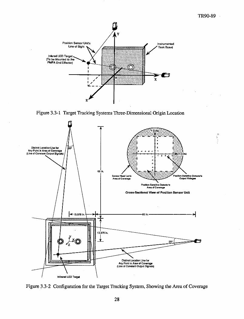
The position of the target, which is mounted on the PFMA's end effector tool, is recorded
by the sensor head and the two-dimensional reference voltages transmitted as an analog input to the
position controller. The sensor heads are mounted 78.375 inches along the X and Y axis from the
center point of the resupply station's instrumentation board and 3 inches in the positive Z direction,
as shown in Figure 3.3-1. By placing the sensor head 3 inches in the positive Z direction, a larger
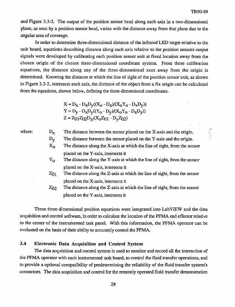
area of coverage in front of the instrumentation board is obtained. The area of coverage of the
sensor heads is a 20 ° cone shape. This two-dimensional X-Y view of the area of coverage is
shown in Figure 3.3-2. By placing the sensors heads 90 ° apart, the three-dimensional envelope of
coverage resembles an odd shaped box. This arrangement will provide a three-dimensional
location of the PFMA end effector tool in reference to the resupply station instrumentation board's
center.
Each position sensor unit, or sensor head, sees a two-dimensional plane. The output of the
position sensor control unit is in the range of +_5 volts, for each of the two-dimensions seen,
corresponding to the location in which the fight from the infrared target is projected onto the screen
of the sensor head. Therefore, the output of the position sensor control unit describes a unique line
in space, originating from the center of the position sensor head's lens, as shown in Figure 3.3-1
27
Position Sensor Unit's /t y
Line of Sight _/ ======================
Infared LED Target _
('ro be Mounted to the _ /_PMFA End Effector)
I
' iNI .
I ¢
I/, S
I
I
/'
::::::::::::::::::::::::::::::::::::::::::::::::::::::::
!'0iiiiiiiiiiiiiiiiiiiiiiiiiiiiiiiiiiiiiiiiiiiiiiiiiiiiiiiiiiiiii
r
lnstrumented
Task Board
TR90-89
Figure 3.3-1 Target Tracking Systems Three-Dimensional Origin Location
DistinctLocation LineforAny Point InArea of Coverage
(Lineof ConstantOutput SI
65 In.
Po_tion-,Sen_tveDetectodsAreaofCoverage
Cross-Sectlonal View of Position Sensor Unit
65 in.
13.375 In.
DistinctLocationLInefor
Any Point in Area of Coverage(Line ofConstant Output Signals)
Infrared LED Targe(
Figure 3.3-2 Configuration for the Target Tracking System, Showing the Area of Coverage
28
TR90-89
and Figure 3.3-2. The output of the position sensor head along each axis in a two-dimensional
plane, as seen by a position sensor head, varies with the distance away from that plane due to the
angular area of coverage.
In order to determine three-dimensional distance of the infrared LED target relative to the
task board, equations describing distance along each axis relative to the position sensors output
signals were developed by calibrating each position sensor unit at fixed location away from the
chosen origin of the chosen three-dimensional coordinate system. From these calibration
equations, the distance along any of the three-dimensional axes away from the origin is
determined. Knowing the distance at which the line of sight of the position sensor unit, as shown
in Figure 3.3-2, intersects each axis, the distance of the object from a fix origin can be calculated
from the equations, shown below, def'ming the three-dimensional coordinates.
X = D x - DxDy((X o - Dx)/(XoY o - DxDy))
Y = Dy - DxDy((Y o - Dy)/(XoY o - DxDy))
Z = Z01Z02Dy/(XoZ01 - DyZ02 )
where: Dx
Dy
Xo
Yo
Z01
Z02
The distance between the sensor placed on the X-axis and the origin.
The distance between the sensor placed on the Y-axis and the origin.
The distance along the X-axis at which the line of sight, from the sensor
placed on the Y-axis, intersects it
The distance along the Y-axis at which the line of sight, from the sensor
placed on the X-axis, intersects it
The distance along the Z-axis at which the line of sight, from the sensor
placed on the X-axis, intersects it
The distance along the Z-axis at which the line of sight, from the sensor
placed on the Y-axis, intersects it
These three-dimensional position equations were integrated into LabVIEW and the data
acquisition and control software, in order to calculate the location of the PFMA end effector relative
to the center of the instrumented task panel. With this information, the PFMA operator can be
evaluated on the basis of their ability to accurately control the PFMA.
3.4 Electronic Data Acquisition and Control System
The data acquisition and control system is used to monitor and record all the interaction of
the PFMA operator with each instrumented task board, to control the fluid transfer operations, and
to provide a optional compatibility of predetermining the reliability of the fluid transfer system's
connectors. The data acquisition and control for the remotely operated fluid transfer demonstration
29
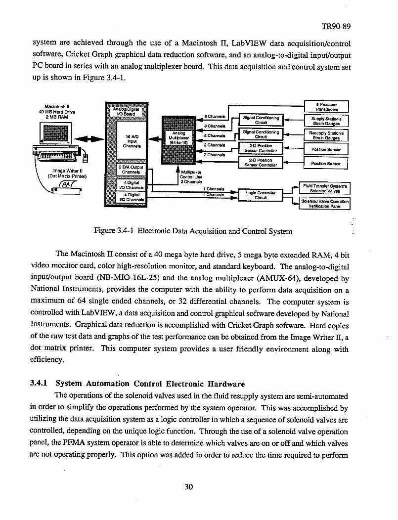
TR90-89
system are achieved through the use of a Macintosh II, LabVIEW data acquisition/control
software,CricketGraph graphicaldatareduction software,andananalog-to-digital input/output
PC boardin serieswith an analogmultiplexer board. This dataacquisitionandcontrol systemsetup is shownin Figure 3.4-1.
Figure3.4-1
1I
AnalogMultiplexer
(64oto- 16) 2 Channels
2 Channels
lexe"_
I Line
I 2 Channels
1 Channels
4 Channels
I 8 Pressure I
Transducers
Signal Conditioning
Circuit _ Supply Station's8 Channels Strain Gauges i
Signal Conditioning8 Channels Circuit H ResupplYStrainGaut_esStati°n'sI
d 2-D PositionSensor Controller _ Position Sensor i
I 2"O P°sitl°n I'_" i JJ Sensor Controilsr Pesition Sensor
,,,..iLogic Controller
._ CircuitFluid Transfer System's
SelenJod Valves i
8olenlod Valve Operation IVeritlcatlon Panel I
Electronic Data Acquisition and Control System
"2
2
The Macintosh IT consist of a 40 mega byte hard drive, 5 mega byte extended RAM, 4 bit
video monitor card, color high-resolution monitor, and standard keyboard. The analog-to-digital
input/output board (NB-MIO-16L-25) and the analog multiplexer (AMUX-64), developed by
National Instruments, provides the computer with the ability to perform data acquisition on a
maximum of 64 single ended channels, or 32 differential channels. The computer system is
controlled with LabVIEW, a data acquisition and control graphical software developed by National
Instruments. Graphical data reduction is accomplished with Cricket Graph software. Hard copies
of the raw test data and graphs of the test performance can be obtained from the Image Writer II, a
dot matrix printer. This computer system provides a user friendly environment along with
efficiency.
k
3.4.1 System Automation Control Electronic Hardware
The operations of the solenoid valves used in the fluid resupply system are semi-automated
in order to simplify the operations performed by the system operator. This was accomplished by
utilizing the data acquisition system as a logic controller in which a sequence of solenoid valves are
controlled, depending on the unique logic function. Through the use of a solenoid valve operation
panel, the PFMA system operator is able to determine which valves are on or off and which valves
are not operating properly. This option was added in order to reduce the time required to perform
30
TR90-89
maintenanceno thesystem,suchastroubleshootingtheelectronicscircuits and computer errors in
the controlling of the solenoid valves.
In order to control the fluid resupply system's solenoid valves, a sequence of valve
operations were determined and a unique logic function for each sequence was developed. Figures
4.2.2-1 and 4.2.2-2, in section 4.2.2, lists each system function, operation, valve sequence order,
logic function code, and verification of the operation for liquid and gas transfer. A total of 39
solenoid valve sequences were defined in order for the system to be able to preform required
operations. From this list, it was determined that a maximum of 26 logic functions (0-25) are
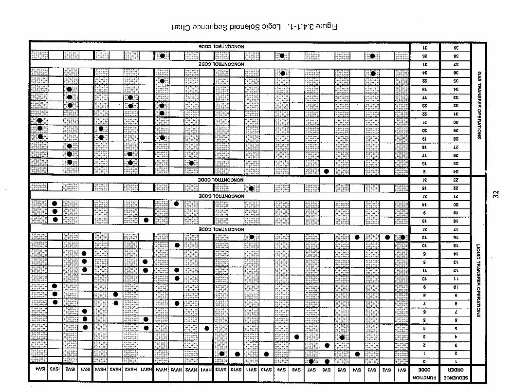
needed to control the fluid resupply system, along with one noncontrol function (31). A chart
showing the valve sequence order corresponding to the logic function code and solenoid valve
openings is shown in Figure 3.4.1-1.
The solenoid valves are controlled by outputting a logic function code from the computer to
a logic circuit that turns on a set of relays and activate the desired valves. LabVIEW is used to
write a binary word to a four bit digital output port and one analog output ports of the A/D board.
These outputs are connected to four 3 x 8 decoders, with three enable lines, which will provide the
possibility of 32 logic operations. These outputs are connected to a series of logic gates which
control each solenoid valve relay. The logic circuit is shown in Figure 3.4.1-2. A logic control -2
circuit was designed to activate the relays controlling the solenoid valves. The logic circuit was
constructed by using the wire wrapping method in order to accommodate any future change
requirements and to reduce the circuit board size, as compared to the required printed circuit board
size.
The solenoid valve sequences were semi-automated in order to activate each sequence
separately. Initially, this was done in order to fine tune the system, determining the time required
to verify the completion of each function. The fluid transfer system that was delivered could be
further automated through LabVIEW software. Related chronological operations can be controlled
by selecting a single switch located on the LabVIEW panel on the computer screen.
In order to verify that each relay is activating the appropriate solenoid valve when required,
a valve operation verification panel was designed. The system's operator is able to determine
which valves are not operating properly, through the use of the fluid transfer solenoid valve
operation verification panel. A neon light was connected in parallel with each solenoid valve, at the
corresponding relay that activates that solenoid valve, to verify whether the solenoid is receiving
current. The panel, which is placed near the system operator, consists of a simplified version of
the fluid transfer system's hardware schematic, with each solenoid valve's representative neon
light illuminated when activated. The panels simplified schematic is shown in Figure 3.4.1-3.
During the demonstration, the output of the 9 pressure transducers are displayed on the
computer screen as digital readouts. Four of these pressure transducers along with some additional
software can be utilized in order to determine the helium leakage rate of the system prior to the
31
_eqo aouenbes p!ouelos o!6o-1 "L- L'#8 eJn6!4
aO00 Io&LNbONON
::1OOO"IOH,LNOONON
]:]:]:i:i:i:_:i:]:i:i:i:i :::::::::::::::::::::: :::::::::::::::::::: _'""''" "" .....,..,-...-..... -----...., ............ .-.---...'.'.'. ........... .,,-...,,....-...- -...,,..,......... ..... .-..................
:i:]:]:!:!:]:[:i:i:i:i:i:] :::::::::::::::::::::: .................... :::::::::::::::::::::: ..................... "::""'::" ..... ::':':':':':'::: ::i:]::::::::::::::: ...................... ...................... "...................
:::i:i:i:!:!:]:i:i:i:i:i:i ,'.'. ".-.... ::::::::::::::::::::: :::::::::::::::::::::: :.:.:.:.:.:.:]:]:]:]:! :.:.:.:.:.:.:.:.:.:+ _.:-.-:.:.:.:......, ::::::::::::::::::::: .,................ [[]:]:]:[:[:]:[:[[ ':':':'::" : •................!iiiiiiiii]!i!!!!iiiiiiiii :::::::::::::::::::::: '::i:i;i:i:i:i:i:i:i:i: iliiii_iiiiliiiiiiiiii :::::::::::::::::::::: :::::::::::::::::::::: !:!!!i!!!_i_!i}ililili: ::::::::::::::::::::: :::::::::::::::::::: :::::::::::::::::::::: :iiiiiiiiiiiiiiiiiiii:: i!ii!ii!ii!ii_ii!i!!!i ::::::::::::::::::::
.,, ...... ".......... '::]:i:i:i'_:ii:_:i.: :::::::::::'::: '""'''"'' "::':':':':':+:: ::::::::::::::::::::::: :i:!::2::!:::::!:! i:!:!:i:!:!:_:]:i:i!i! :iiii!iii!iii:i:i:i:_:i :::::::::::::::::::::: i!!!!!!!!!!!!i!:!!!iiiiiiiii!!!!_iiiiii_iiii iiiO}:::i}:i::i !:i:i:i:!:i:i:i:i:!:i: ii::::[O]]]i]i]] i:i:i:i:i:i:i:!:i:_::' :..................... _i_iiiiiiiiiiii!iiil iiiiiiii![ii[i!!ii!i!i! :i:!:i:!:i:i:!:i:i:i :i:i:i:i:!:i:!:_:i:_:! i:i:i:i:i:i:i:i:i:i;i: ::!:i:_:_:i:i:i:i:i:i; :i:!:i:!:!:i:!:i:!:!:::::::::::::::::::::::: ......... :::::::::::::::::::::: i!!iiiiii!iiiiiiiiii _i_]_i_iiiiiiii!i!i :::::::::::::::::::::: ,:-:-:.:.:-:.:.:-:-:.:. iiiililiiiiiiiiiiiii iiiiiii!i!]!i!i!i!i!i! !iiiiiiiiii_i!}!i!!!!i !!!i![!ii!ii_iiiiil]!! iii[i]iiiii!iiiiiiii
:::::::::::::::::::::::: "'""'" "" """ ' ''" ' " '""" '"" "'"'"" '"''''" :"::':::::: ........... iiiiii][iii!iii]iiii
:':':':':':':':'::':':':" :::::::::::::::::::: ======================::::::::::::::::::::: :::::::::::::::::::::: ::::::::::::::::::::: ...................... '"'''"" ::::::::::::::::::::: :::::::::::::::::::::: ::::+:::'::':" :!:i:i:!:!:!:!:!:!:i
i::i::ii{::i_i::!il .................................................................................................................................•............................................................................................ ,.,....... !:!:!............. i:::::::::::!:....... _:!:_:_:_:_:_:_:_:_:::_:_:_::::::::::::: :::::::::::::::::::::::::::::::::::::::::::: :_ ..................... _!!_!_ !:i:i:i:i:i:i:!:i:i:i: !_i_i_i_i_i_i_:._i_{_
...................:.; _:]!i!!!i!!i!:ii:::- .:.:.:.....:.:... i:i:]:i:i:i:i:i:i:]:!: :::::::::::::::::::: ::::::::::::::::::::::: [:]:]:i:i:i:i:i:]:]:i: ::!:!:]:!:!:i:!:!:!:............... .... i!:.!i!:.!]!!i:.!ii!:::: i:i!i_iii_i!i!i!_]i_ :::::::::::::::::::::::i]:.!:.!:.!i!:.![[:.!:.!:.!.=
.......---........... :]:]]]]]]:::!]!]]]]:]] .......•........... :::::::::::::::::::::: ;.;............ ::::::::::::::::::::: ======================:::::::::::::::::::::: ;:::::;::::::::::::: i]i!!!i!iiiii!]:::::: iiiiiiil]i]i_i[]]i]ii! iii]i!i!ii!![ii!!!i;! _!!iiiiiiil]]!_[i_i_iliiiiiiiii;iii!ililiiiiii ....................................................................................................................................................................................................................:::::::::::::::::::::: _iiiiiiiiiiiiiii:ii!:: ...................................................................................................................................................................................... i!!i!!iiiiiiiiiiiiii............. :':::+:::: :::::::::::::::::::::: ':':':'::::::: :::::::::::::::::::: :::::::::::::::::::::: :::::::::::::::::::::: :::::::::::::::::::: ::::::::::::::::::::: :::::::::::::::::::::: ::::::::::::::::::::::: :!:i:!:!:i:!:]:]:!:]
;_i_i_ i::i::iO::i::i::i::....................:::::::::::::::::::::........................................._!_!_!_!!!!i!i!ili_......................................................................................_::_::_::_i_::!::_i_i_}:;::__!_ii!!!!ii!i!i;!!!;:::::::::::::::::::::::::: :::::::::::::::::::: ::::;::::::::::::::: :::::::::::::::::::: :::::::::::::::::::::: :::::::::::::::::::: ::::::::::::::::::::: :::::::::::::::::::::: ,.,. r'T ::::::::::::::::::::::.i_ii.iii_i_iiii_I ' T'''; ":';':';':':':":': ...... ;':':':" :::::::::::::::::::::: ======================:::::::::::::::::::: :':'i'?i':':':'i+: :':':':':':':':':':':" " ........... . ...... "
........................ :...................iiiii_iiiiiii ....................}iiiiiiii :_iiiiiiiiiiiiiiiiiii_iiii_:_ii::i::iiiii::i::iii:!i!i!!ii!i!i!iiiiii::_:_:i:i:i:i:i:i:i:i;i:i:i:i:i:i:i:!:!:i:i:::::::::::::::::::::::::i:i:i:i:i:i:i:i:i:i]]]]]]]]i!]]]]]]]]]]]]]]]]]]]0]]]]]][ ::::::::::::::::::::: ] _]]]]_]]]i]i]i]]i_: ............................................ .................................................• " • "-'.. ...... ''"'''-""-'- ?::i:i:!:i:::i:i:i:i:i: ii!i!i!i!!!i!!!!!!!! """'''' ''""'"'"" ::::::::::::::::::::
::::::::::::::::::::: ::::::::::::::::::::::: :.:.:.:.:+:.:.:.:. ;::::::::::::::::::: :.:.:.:.:.:.:........ ;.:.:.:.:.:+:+:.:. ............ ............... ................. .................... ..........
......I]] ' "'"""'"" " """'""I" '"""""""" ".......... " '""'[" """"''"' :::::::::::::::::::::::"" :i.....
=IOOO "IOI:IINOONON
=laoo "IOI:IINOONON
iiiiiiiiiiiiiiiiiiiiiiiii ............................•................. ::::::::::::::::::::: ...................... ................... ..................
,'-.'.'.'-'.'-'- ".'.'.'.'.'.'.'.'-'-" ::::::::::::::::::::: :::::::::::::::::::: :::::::::::::::::::::: :::::::::::::::::::::: ::::::::::::::::::::: !!i!!!i!i!!!i!i!_!!!ii ............ !!i!!ii!ii!!i!i!!!i!
.............. -.-.,....-......... ::::::::::::::::::::: :::::::::::::::::::::: .:.:.:.:.:+:.:.:.:._ iii_ii_ii_iiiii]iiii .:_:i:i:i:i:i:i:!:i:i: }}!iiiiii!i_iii_iiii!i :i:i:i:i:i:i:!:!:i:!:! :ii!iii!i!_i_iiii_ii :::::::::::::::::::::: ::::::::::::::::::::::: :':':':::':':':':
•-'-'.-----...'. ............. ...-.-..-.-..-............. :::::::::::::::::::::: :::::::::::::::::::::: _}ii_iiiiiiiiiiiiii: !i!i!i!i!i!]!!]i!!!! ili!ii_ii!iiiiiii_iii_ iii[ii!iiii}ii!i!i!i}i: """'""
'=1OOO"IOI=IJ.NOONON
:!:!:!:i:i:i:i:i:i:i:i:i:!:i:i:_:i:i:i:i:i:i:i_!i!i_i_iiiiiiiiiiii...........................................tliiiiiiiiiiiiiiiii}ii :!!_iii_!i_iii_iiiiii::i::i::ii::i::i::i.........._.............................................................................:::::::::::::::::::::::::: :::::::::::::::::::::: :::::::::::::::::::: :::::::::::::::::::::: ..-.......-........ .................... .:.:.:+:.:+:.:.:.: .:.:.:.:.:+:.:.;.: .................... .:.:.:.:.:.:.:.:+:.: • .........
........... i:'_ii_i'iiii'ii ........... ::::::::::::::::::::::: :::::::::::::::::::::: :iiiiiiii_iiii!i!iiiii :!!!!i!i!!!i!i!i!!!i! :::::::::::::::::::::: i:i:i:i:i:i:i:i:i:i:i: :!!!;!:!;i_!_!_!_i
:':':':+::::':':':" i:i:i:i:_:_:i:i;i:i:i ::::::::::::::::::::: :::::::::::::::::::::: .'..'.'.'.'-.... .'...'.'.'.'.'.'.'. -----..-... ...'.'..'.'.'.'." ---'---------... ............ .'.'.'.'.'.'.-.-.-.
.......... ::::::::::::::::::::: :::::::::::::::::::: :::::::::::::::::::::: ::::::::::::::::::::: :i:i:i:i:!:!:!:]:i:!: i!]!!!!!!!!!!!!!!i!i !ii[i!i!i!i!i!!!i!i!!i :::::::::::::::::::::: iiii!i!i!i!i!!!i!i!i iii!iiii:iiiiiiil]:ii[ iiii_i_i!]iiiili!iiiiii iii!iiiiiiii[![!!!i!
::}::_i!i!]ii_}iiiii_i_}.....................• ..........................................• _:_i_!_i!!_i_i:• i::i::}ii]i::iii]}]i::i::]............................................................................................................:::::::::::::::::::::::i;iiiii;i;i;i':i;iiii::::::::::::::::::::::::: .:.:.:+:+:.:.:.:. :::::::::::::::::::: -.....-.....-......... ............... ................... ...................... :::::::::::::::::::::: .................... .:+:.:.:.:.:.:.:+: .:.:.:.:.:.:.:.:.:.:.:............. . ........... -...,.....- :::::::::::::::::::::: .:.:.:.:.:.:.:.:+: ................... ::::::::::::::::::::: ::::::::::::::::::::::: ======================:ii!i!i!i!i!!!i!i!!!! "-""'-'-"'-'-'- :::::::::::::::::::::: i!!i!i!i!i!!!!!i!!i:
::::::::::::::::::::::::::: ::::::::::::::::::::: :i:_:i:i:}:i:i:i:i:i :!:}:!:]:}:]:i:}:}:}:! :::::::::::::::::::: [}!!}}!!!]!!}i!iii!i.. }}!]i]!!!}!i!!}}}}}!}i: iii!i]iiiii}i!i}iii!] }}i!i}}!}!}!!!!!!i!} iiiili!iiiiiiii!i}_}ii iii!}!}i}!i}_}i}iii!}! ::!::i::!::!::}::!::ii!::!::!
]]]]]]!]]]]][]]]]]][]]]]]]]• ............................................................................................................................................................................................................................................ _:_:_:::_:_:_:_:_:_
.............. ........... ...-............... .............. ...................... :::::::::::::::::::: .....-.-.............- ...................... ::::::::::::::::::::•..'.'.'-'.'-'.'-'.'.-. ::::::::::::::::::::: :::::::::::::::::::: :::::::::::::::::::: ::-:'::':'::':':' :::::::::::::::::::::: :i_iiiiiililiiiiii!: !i!iii!i!iii!ii_!i!ili: :::::::::::::::::::::: :::::::::::::::::::: !iiiiiii!i!i!i!i!i!i!i ii!i!i!i!i!i!!ii!i]i!i ::::::::::::::::::::
i;i ............................................................ ............. .................... ................ ................. .................. ................... ...................... . ................ :.:.:.;.:.:.:.:.:.:.i ii::i!iii::i!i::iiil}ili• _:_:_:i:_:_:_:_:_:_:_..................... • ..........................................• ......................:.....................................................................................................................................................ii!i!i!]!!:]:]:i:]:i:: :i:i:i:i:i:[:i:!:i:] .................... !il]!!!!ilil]i!i!i!] !]!]!]i!iii_iiiii}]] ......_:::::::i:i:!: i]]!]ii!]i!!:.!]!!..... _!i]il]!_!i!i:]iii]i] :i:!:::!:!:::!:i.... :...............................................................
i!ilili!i!iiiiiiiiiiiiii! .....................• i:i:i:i:i:!:!:i:i:!: :_:_:i:i:iiiii:i:i:i:_ :........................................ :................... _...................... _i:i:ii_:i:i_i:i_:ii_ .......................................... :iiiiiiiii:i:iiiiiii:i ::::::::::::::::::::::::
......... ::+:':':+::': ::::::::::::::::::::::: i:i:i:i:i:i:i:i:i:_::iii::!::i::i::i::i::iiiiiii::iii:::::::::::::::::::::::::::::::::::• :::::::::::::::::::::::::::::::::::::::::::::::::::::::::::::::::::• :::::::::::::::::::::::::::::::::::::iiiii::iiii::ii::iiii}::::::::::::::::::::::::::::::::::::::::::::::::::::::::::::::::::::::::::::::::::::::::::::::::::::::i}:::i}:iiiiiiii::iii..............................................:.......................................... "......... :':::":::::: ":+:+:':':':':': :::::::::::::::::::: ::::::::::::::::::::::: i:!:i:i:!:i:i:i:i:_:::::::::::::::::::::: :::::::::::::::::::: :::::::::::::::::::: '""" "" :::::::::::::::::::::: i_iiiiii!iii_iiiiiii :iiii:iil]iii!i}[!i!ii! :::::::::::::::::::::: :::::::::::::::::::: ::::::::::::::::::::: ::::::::::::::::::::::: :::::::::::::::::::::
.-.-.-...-.-.-.-....-.., :::::::;::::::::::: ::::::::::::::::;::: :::::::::::::.:::::: :::::::::::::::::::: ..................... ................. ............... :::::::::::::::::::::: ............ ............ ::::::::::::::::::::::: :::::::;::::::::::::}:}:i:!:!:i:!:i:i:!:!:i: ::::::.:.:.::::::::: :::::::::::::::::::: iiiiiiiiiiiiiiiiiii! :::::::::::::::::::::: :::::::::::::::::::: :::::::::::::::::::::: :::::::::::::::::::::: i:i:i:i:i:!:!:!:i:!:!: ..,,,..,..,......
========================.'.'.-'-'--..'.'.'. -.......-. .:::.:::::.:.:.:.:.: ..................... :'.:i:i:]:'.:!:'.:!:!:!i '" ' "'""' ' i i:i:i:i:i:i:ii:i:i .'.'..w.'/.'. .......... :':':':'::;_:i: :::::::::::::::::::::
:::::::::::::::::::::::: ''"'''" [ii[iiiiiiiiiiiii!il :::::::::::::::::::: :.:.:.:.:.:.:.:.:.:.:. ..................... :::::::::::::::::::: :::::::::::::::::::::: :::::::::::::::::::::: .i:]:i:i:i:i:i:i:i:i:i • !:!:!:i:!:i:i:i:i:i: :i:i:i:!:i:i:i:i:i:i:i :i:i:iii:iiiiiiiiiii:_:_:::::_:_:"''" .:-:.:.:.:.:.:.:.:-:-: :::::::::::::::::::: :::::::::::::::::::: ::::::::::::::::::::: ]i!!i!i!ii_iii_iiiiiii :::::::::::::::::::: i:i:!:i:i:!:!:i:!:i:i: _iii_!_il]]ii]iii_iiii ::::::::::::::::::::: ::::::::::::::::::::: :i!!!!!!i[i!i!i!i!!i!!i iiiiiiiiiiiiiiiiiiii
:i:_:i:i:_:_:i:i:i:i:i:iii!i!ili_iiiiiiiiiiii_i!i!!i_]:i_;_i_iii.....................iiiiii!iiiii!iiiii!i! iiiililil]_i_iiiiiiii]]ii]j[]]::i• ]ili]i]i]i]i]i]i]i]i]i• :::::::::::::::::::::::::::::::::::.......................................................................................!:.::.:.::.:.:.:![!]!:!!:.:.:.:.!!.......................................... _ii_ii_i_ ............................................ ...................... ..................... ii_:._i_ • ...................... _
t,ASI £ASI ;_ASI LASI I_ASH £ASH{ _ASH I.A£H I_AAH £AAH _:AAH LAAH £1.AS !;_LAS LLAS 0LAS 6AS 8AS /.AS 9AS SAS t:'AS £AS ;_AS LAS
L£ 6£
S'_ 9£
I.£ L£
t,_ 9£ 5")
2]81. t,£ _,
zLL ££ t_
=11f11
OL£ "_
m
Z
6L 6_
9L SZ
L£ £Z
L£ i,_
t'l. O_
6 6L
£L 81,
L£ LL
_1. 9L
OL SL
9 t,L
LL _L
OL LL
6 OL
B 6
L 6
9 L
G 9
L
0 L
gO00 1:1301:tO
NOI/ONn=! gON=lrIOgS
r-DC:
_3
-I
zt/)"11m'11
0
111m
"4
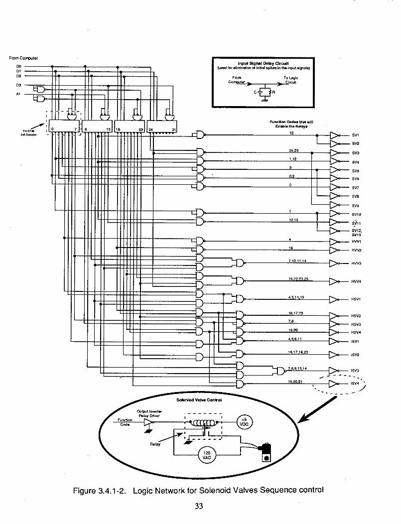
From Computer
DO
D1
D2
D3
AI
Input Signal Delay Circuit
(used for eiminadon of ini_al spikes in the input signals)
From To LogicComputer .,_ .,._ Circuit
15 16 24 31
©©©©
Function Codes that will
Enable the Relays
12
24,25
1,12
3
0,2
0
1
12_15
4
16
7,10_11_14
19122,23,25
_,,_ sVlSV2
_ SV3
SV4
SV5
SV6
SV7.
SV8
_._:>o_ SV9
_ SVI0
SVl 2,
SV13
HWlHW2
HW3
HW4
16'17123 _ HSV2
7,8 _O_ HSV3
19120 _ HSV4
ISV1
16j17j18a23 _ tSV2
Soleniod Valve Control _ /
f _ qrrTcrn_--_(,,*2^ _ "_JP"
Figure 3.4.1-2. Logic Network for Solenoid Valves Sequence control
33
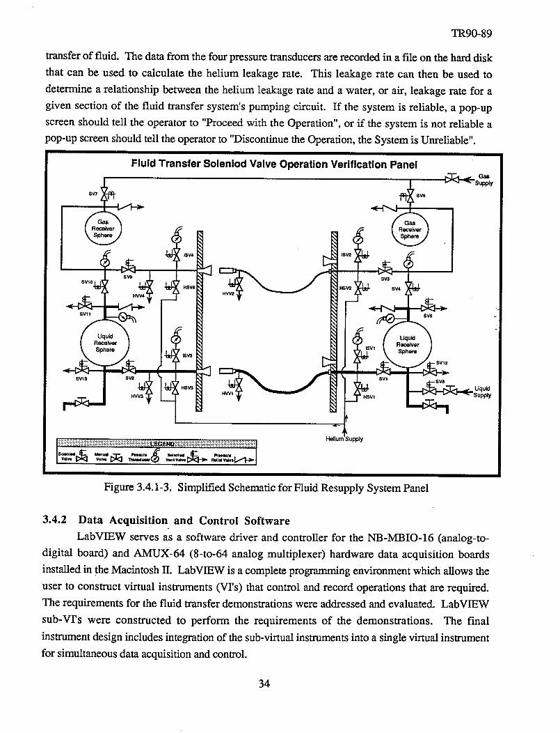
TR90-89
transfer of fluid. The data from the four pressure transducers are recorded in a file on the hard disk
that can be used to calculate the helium leakage rate. This leakage rate can then be used to
determine a relationship between the helium leakage rate and a water, or air, leakage rate for a
given section of the fluid transfer system's pumping circuit. If the system is reliable, a pop-up
screen should tell the operator to "Proceed with the Operation", or if the system is not reliable a
pop-up screen should tell the operator to "Discontinue the Operation, the System is Unreliable".
Fluid Transfer Soleniod Valve Operation Verification Panel
sv,
sv,o_
SV! 1
SV13 SV2 (
SV3
SV4
Liquid
Receiver
Sphere
sv1
I:>T<:l-_s_ v
. Liquid
Supply
Figure 3.4.1-3. Simplified Schematic for Fluid Resupply System Panel
3.4.2 Data Acquisition and Control Software
LabVIEW serves as a software driver and controller for the NB-MBIO-16 (analog-to-
digital board) and AMUX-64 (8-to-64 analog multiplexer) hardware data acquisition boards
installed in the Macintosh II. LabVIEW is a complete programming environment which allows the
user to construct virtual instruments (VI's) that control and record operations that are required.
The requirements for the fluid transfer demonstrations were addressed and evaluated. LabVIEW
sub-VI's were constructed to perform the requirements of the demonstrations. The final
instrument design includes integration of the sub-virtual instruments into a single virtual instrument
for simultaneous data acquisition and control.
34
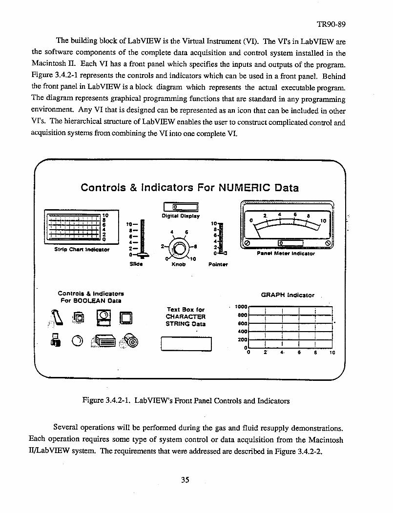
TR90-89
The building block of LabVIEW is the Virtual Instrument(VI). The Vrs in LabVIEW are
the software componentsof the complete dataacquisition and control systeminstalled in the
MacintoshII. EachVI hasa front panelwhich specifiesthe inputs and outputsof the program.
Figure 3.4.2-1representsthecontrols andindicatorswhich canbeusedin a front panel. Behind
thefront panelin LabVIEW is ablock diagram which representsthe actual executableprogram.
The diagramrepresentsgraphicalprogrammingfunctions that are standardin anyprogrammingenvironment. Any VI thatis designedcanbe representedasan icon that canbe includedin other
Vrs. The hierarchicalstructureof LabVIEW enablestheuserto constructcomplicatedcontrol and
acquisitionsystemsfrom combiningtheVI intoonecompleteVI.
Controls & Indicators For NUMERIC Data
Strip Chart In¢licatolr
I l0 IIOigita! Olsplay
:_- , 62 8
Slide Knot3
11[ _]'!°".........................................
0 Psnet Meter Indicator
Pointer
Controls & Indicators
For BOOLEAN Oata
Text Box for
CHARACTER
STRING Oata
GRAPH Indicator
1001I
60OI
i 200 I0
I
0 2 4. 6 8 10
Figure 3.4.2-1. LabVIEW's Front Panel Controls and Indicators
Several operations will be performed during the gas and fluid resupply demonstrations.
Each operation requires some type of system control or data acquisition from the Macintosh
/J/LabVIEW system. The requirements that were addressed are described in Figure 3.4.2-2.
35
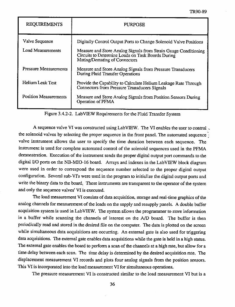
REQUIREMENTS
ValveSequence
Load Measurements
Pressure Measurements
Helium Leak Test
Position Measurements
Figure 3.4.2-2.
PURPOSE
TR90-89
Digitally Control Output Ports to Change Solenoid Valve Positions
Measure and Store Analog Signals from Strain Gauge ConditioningCircuits to Determine Loads on Task Boards DuringMating/Demating of Connectors
Measure and Store Analog Signals from Pressure TransducersDuring Fluid Transfer Operations
Provide the Capability to Calculate Helium Leakage Rate ThroughConnectors from Pressure Transducers Signals
Measure and Store Analog Signals from Position Sensors DuringOperation of PFMA
LabVIEW Requirements for the Fluid Transfer System
A sequence valve VI was constructed using LabVIEW. The VI enables the user to control _.
the solenoid valves by selecting the proper sequence in the front panel. The automated sequence
valve instrument allows the user to specify the time duration between each sequence. The
instrument is used for complete automated control of the solenoid sequences used in the PFMA
demonstration. Execution of the instrument sends the proper digital output port commands to the
digital I/O ports on the NB-MIO-16 board. Arrays and indexes in the LabVIEW block diagram
were used in order to correspond the sequence number selected to the proper digital output
configuration. Several sub-VI's were used in the program to initialize the digital output ports and
write the binary data to the board. These instruments are transparent to the operator of the system
and only the sequence valves' VI is executed.
The load measurement VI consists of data acquisition, storage and real-time graphics of the
analog channels for measurement of the loads on the supply and resupply panels. A double buffer
acquisition system is used in LabVIEW. The system allows the programmer to store information
in a buffer while scanning the channels of interest on the A/D board. The buffer is then
periodically read and stored in the desired file on the computer. The data is plotted on the screen
while simultaneous data acquisitions are occurring. An external gate is also used for triggering
data acquisitions. The external gate enables data acquisitions while the gate is held in a high status.
The external gate enables the board to perform a scan of the channels at a high rate, but allow for a
time delay between each scan. The time delay is determined by the desired acquisition rate. The
displacement measurement VI records and plots four analog signals from the position sensors.
This VI is incorporated into the load measurement VI for simultaneous operations.
The pressure measurement VI is constructed similar to the load measurement VI but is a
36
TR90-89
standaloneinstrument. This VI scansthechannelsselectedandstoresthe informationondisk for
postprocessingandin memory for real time displayof thepressuretransducersof interest. The
leakrateVI will calculatethehelium leakrateof thepressuretransducerselectedon thefront panelof theFluid TransferInstrument.
The main Fluid Transfer VI consists of a combination of all the virtual instruments
describedpreviously. The front paneldesignof the main VI is shown in Figure 3.4.2-3. The
panel allows the user of the system to perform all task requirements of the fluid transfer
demonstration.The front panel consistsof binary switches,numeric input controls and numeric
output controls. Thenumeric input controlsenablethe userof thesystemto changethe sequence
of the solenoidvalves andselecttheproperpressuretransducersfor leak checks. A binary slideswitchis usedin thefront panelto selectthetaskto beperformed. Oncethetaskis completed,the
user can continue with another task selection. Numeric output controls consist of the
supply/resupplypanelforces, pressuretransducerindicatorsandposition sensorindicators. Thebinary switcheson thefront panelareusedto initiate andsuspendtaskoperationsduring the fluidtransferdemonstration.
37
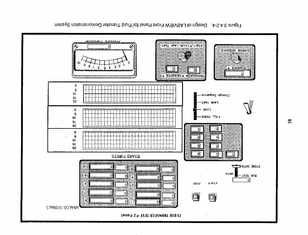
welsX S uo!leJ]suoweG JejsueJ/P!nl_ JOl leUed _uoJ3 AABIASV7 jo u6!seo "#-8"#'8 eJn6!4
deonpsuoJ l eJnsseJ d
"---LOI 6
_....,......,.........,......,.....,°...,,........................+.....................,.....,
i
lliliiiiiiiiiiliiiiiNiiiiiiiiiiiiiiiiiilii_ iiiiiili_iiliI_i_+ +m_....._ _+:_:_+_:,+,+_i_i_!_iw_I@IIIi.... i!,,_o_3nmsii!iiiiilil
0
c
Ol
£I
OZ
0
£
OI
£I
OZ
° +++++++++++++iO_ .........
SIVNglS 907_N_
7___7::'_]:::i i
0
C
_i t
0
---eouenbe$ e6uoq3
POOl
I-'-S_N_I 7719
+++++++.......................++I+.................L+i+i+ii++++i+++++m +++_i+_+ _!+++i !if+if
: :: : :i:_
iliili iiiiii! q[ _]
UlUO _01S
I, ol
laUed _# IS]1 H]JSNYSI OIAIJ
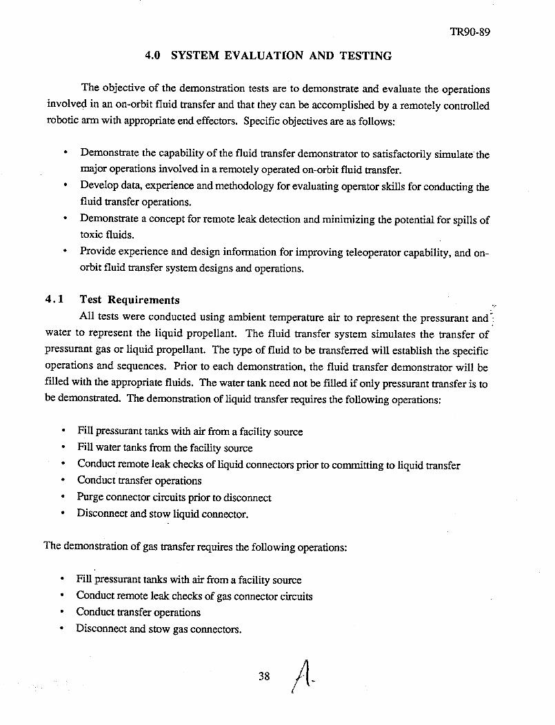
4.0 SYSTEM EVALUATION AND TESTING
TR90-89
The objective of the demonstration tests are to demonstrate and evaluate the operations
involved in an on-orbit fluid transfer and that they can be accomplished by a remotely controlled
robotic arm with appropriate end effectors. Specific objectives are as follows:
• Demonstrate the capability of the fluid transfer demonstrator to satisfactorily simulate the
major operations involved in a remotely operated on-orbit fluid transfer.
• Develop data, experience and methodology for evaluating operator skills for conducting the
fluid transfer operations.
• Demonstrate a concept for remote leak detection and minimizing the potential for spills of
toxic fluids.
• Provide experience and design information for improving teleoperator capability, and on-
orbit fluid transfer system designs and operations.
4.1 Test Requirements _
All tests were conducted using ambient temperature air to represent the pressurant andS:
water to represent the liquid propellant. The fluid transfer system simulates the transfer of
pressurant gas or liquid propellant. The type of fluid to be transferred will establish the specific
operations and sequences. Prior to each demonstration, the fluid transfer demonstrator will be
filled with the appropriate fluids. The water tank need not be filled if only pressurant transfer is to
be demonstrated. The demonstration of liquid transfer requires the following operations:
• Fill pressurant tanks with air from a facility source
• Fill water tanks from the facility source
• Conduct remote leak checks of liquid connectors prior to committing to liquid transfer
• Conduct transfer operations
• Purge connector circuits prior to disconnect
• Disconnect and stow liquid connector.
The demonstration of gas transfer requires the following operations:
• Fill pressurant tanks with air from a facility source
• Conduct remote leak checks of gas connector circuits
• Conduct transfer operations
• Disconnect and stow gas connectors.
15
38
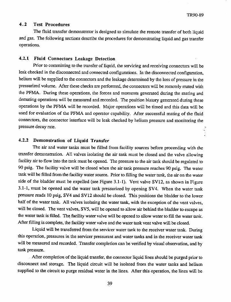
TR90-89
4.2 Test Procedures
The fluid transfer demonstrator is designed to simulate the remote transfer of both liquid
and gas. The following sections describe the procedures for demonstrating liquid and gas transfer
operations.
4.2.1 Fluid Connectors Leakage Detection
Prior to committing to the transfer of liquid, the servicing and receiving connectors will be
leak checked in the disconnected and connected configurations. In the disconnected configuration,
helium will be supplied to the connectors and the leakage determined by the loss of pressure in the
pressurized volume. After these checks are performed, the connectors will be remotely mated with
the PFMA. During these operations, the forces and moments generated during the mating and
demating operations will be measured and recorded. The position history generated during these
operations by the PFMA will be recorded. Major operations will be timed and this data will be
used for evaluation of the PFMA and operator capability. After successful mating of the fluid
connectors, the connector interface will be leak checked by helium pressure and monitoring the
pressure decay rate. -:
4.2.2 Demonstration of Liquid Transfer
The air and water tanks must be filled from facility sources before proceeding with the
transfer demonstration. All valves isolating the air tank must be closed and the valve allowing
facility air to flow into the tank must be opened. The pressure to the air tank should be regulated to
90 psig. The facility valve will be closed when the air tank pressure reaches 90 psig. The water
tank will be filled from the facility water source. Prior to filling the water tank, the air on the water
side of the bladder must be expelled (see Figure 3.1-1). Vent valve SV12, as shown in Figure
3.1-1, must be opened and the water tank pressurized by opening SV4. When the water tank
pressure reads 10 psig, SV4 and SV12 should be closed. This positions the bladder to the lower
half of the water tank. All valves isolating the water tank, with the exception of the vent valves,
will be closed. The vent valves, SV5, will be opened to allow air behind the bladder to escape as
the water tank is filled. The facility water valve will be opened to allow water to fill the water tank.
After filling is complete, the facility water valve and the water tank vent valve will be closed.
Liquid will be transferred from the servicer water tank to the receiver water tank. During
this operation, pressures in the servicer pressurant and water tanks and in the receiver water tank
will be measured and recorded. Transfer completion can be verified by visual observation, and by
tank pressure.
After completion of the liquid transfer, the connector liquid lines should be purged prior to
disconnect and storage. The liquid circuit will be isolated from the water tanks and helium
supplied to the circuit to purge residual water in the lines. After this operation, the lines will be
39
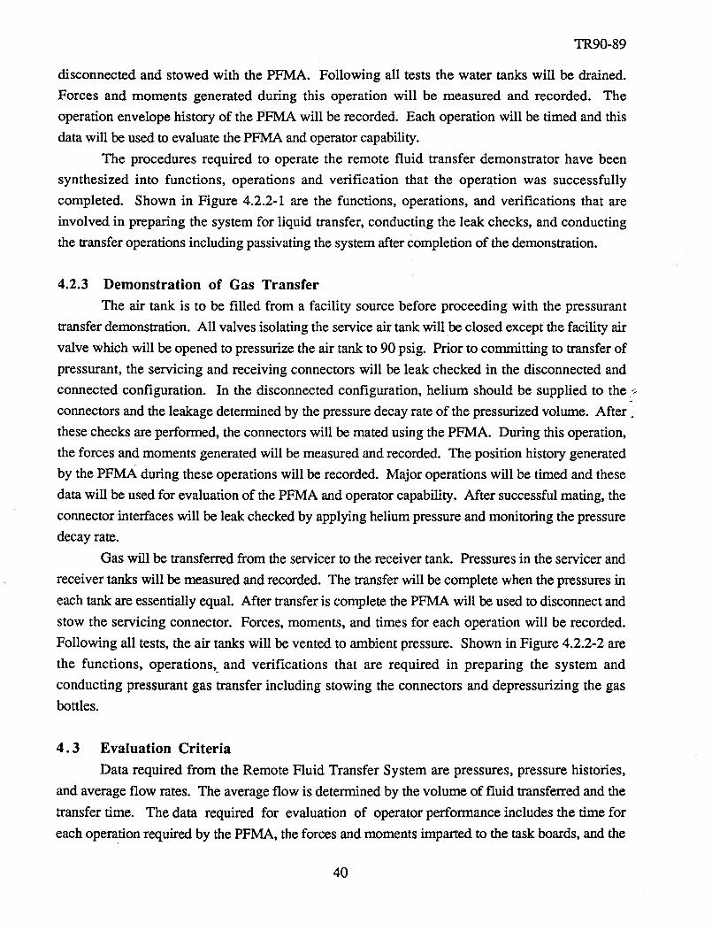
TR90-89
disconnectedand stowed with the PFMA. Following all teststhe water tanks will be drained.Forces and moments generatedduring this operation will be measuredand recorded. The
operationenvelopehistory of thePFMA will be recorded.Eachoperationwill be timed andthis
datawill beusedto evaluatethePFMA andoperatorcapability.
The proceduresrequired to operatethe remote fluid transfer demonstratorhave been
synthesized into functions, operations and verification that the operation was successfully
completed. Shown in Figure 4.2.2-1 are the functions, operations,and verifications that are
involved in preparingthe systemfor liquid transfer,conductingthe leak checks,and conductingthetransferoperationsincludingpassivatingthesystemaftercompletionof thedemonstration.
4.2.3 Demonstration of Gas Transfer
The air tank is to be filled from a facility source before proceeding with the pressurant
transfer demonstration. All valves isolating the service air tank will be closed except the facility air
valve which will be opened to pressurize the air tank to 90 psig. Prior to committing to transfer of
pressurant, the servicing and receiving connectors will be leak checked in the disconnected and
connected configuration. In the disconnected configuration, helium should be supplied to the -:=
connectors and the leakage determined by the pressure decay rate of the pressurized volume. After
these checks are performed, the connectors will be mated using the PFMA. During this operation,
the forces and moments generated will be measured and recorded. The position history generated
by the PFMA during these operations will be recorded. Major operations will be timed and these
data will be used for evaluation of the PFMA and operator capability. After successful mating, the
connector interfaces will be leak checked by applying helium pressure and monitoring the pressure
decay rate.
Gas will be transferred from the servicer to the receiver tank. Pressures in the servicer and
receiver tanks will be measured and recorded. The transfer will be complete when the pressures in
each tank are essentially equal. After transfer is complete the PFMA will be used to disconnect and
stow the servicing connector. Forces, moments, and times for each operation will be recorded.
Following all tests, the air tanks will be vented to ambient pressure. Shown in Figure 4.2.2-2 are
the functions, operations, and verifications that are required in preparing the system and
conducting pressurant gas transfer including stowing the connectors and depressurizing the gas
bottles.
4.3 Evaluation Criteria
Data required from the Remote Fluid Transfer System are pressures, pressure histories,
and average flow rates. The average flow is determined by the volume of fluid transferred and the
transfer time. The data required for evaluation of operator performance includes the time for
each operation required by the PFMA, the forces and moments imparted to the task boards, and the
40
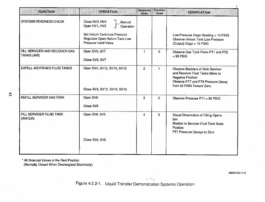
_iiiiiii]]iiiiiiiiiii[ii_iiiii]ii_i!_!!!H_i_ii!i_iii!i!iii!!_!iii_i_i!;i;_iiiiiiiiiiiiii]]]iii]]iiiii!ii_i_!ii_i_!_]]_]_i_i;i_i;_;_!]iiiiii_i]!_i!i!_ii!iiiii!i_iii_iiiiiiiiiii]iii_iiiiiii_!_i_;;!ii_;ii_i!i!i;_i_%_!_iiiii!i_!_ii_i_i_i_i iiii_¢_i_i iiiii]iiii_i_ii]iiiiiiii]iiiiii_i_;ii!_i_i_i_i_i_i_i_i!i_i_i_i_i_!ii_iiiiiiiiiiiiiiiiii_!_!_i_i;i_i_i_i_i_i_i!ii_!iii!!_iiii!iii_i_i_!_!iii!iii_ii!i!i_!iii_i_UN_|_iiiiiii!!_!i_!_i!_iii!i_iiii_i_iii_!_iiiiiiii!iiii!iiiii!!_!_! .... .._TlONiiii!iiii_!_i!iiiii!_i_iili::::i_:::!_!::::i:!i ............:::::::::::::::::::::::::::::::::::::::::::::::::::::::::::::::::::::::::::::::::::_................................................... E_|_|_T|_N:: ............................................................:::::::::::::::::::::::::::::::::::::::::::::::::::::::::::::::::::::::::::::::::::::::::::::::::::::::::::::::::::::::::::::::::::::::::::::::::::::::::::::::::::::::::::::-:-:-- - .:,:........... :................ :i :::::: ............................ ::"' :' : : :: : :: :: :: : : ::::::::::::::::::: : : ::: : :::::::: _ ::::: ura_::: : -:: :. _+:+:. :+:+:+:+:- <.................................................... .- ...+:: :+:+:+:+x x :+:+:+:+: ...................
SYSTEMS READINESS CHECK Close HV3, HV4 - __ Manual
Open HV1, HV2 __ Operation
Set Helium Tank Low Pressure
Regulator Open Helium Tank LowPressure Hand Valve
.... ............... ...............................................................................................TANKS (AIR)
,; Close SV6, SV7
EXPELL AIR FROM 2 FLUID TANKS Open SV4, SV12, SVl0, SV13 .
Low Pressure Gage Reading = 15 PSIGObserve Helium Tank Low Pressure
(Output) Gage = 15 PSIG
REFILL SERVICER GAS TANK
FILL SERVICER FLUID TANK
(WATER)
1 0
2 1
Close SV4, SV12, SVl0, SV13
Open SV6
Close SV6
Open SV8, SV5 4
Close SV8, SV5
3 2
Observe Gas Tank Press PT1 and PT2
= 9O PSIG
Observe Bladders of Both Servicer
and Receiver Fluid Tanks Move to
Negative Position
Observe PT7 and PT8 Pressure Decayfrom 50 PSIG Toward Zero.
Observe Pressure PT1 = 90 PSIG
3 Visual Observation of Filling Opera-tion
Bladder in Servicer Fluid Tank GoesPositive
PT7 Pressure Decays to Zero
* All Soleniod Valves in the Rest Position
(Normally Closed When Deenergized Electrically)
Figure 4.2.2-1. Liquid Transfer Demonstration Systems Operation
880801GC 1115
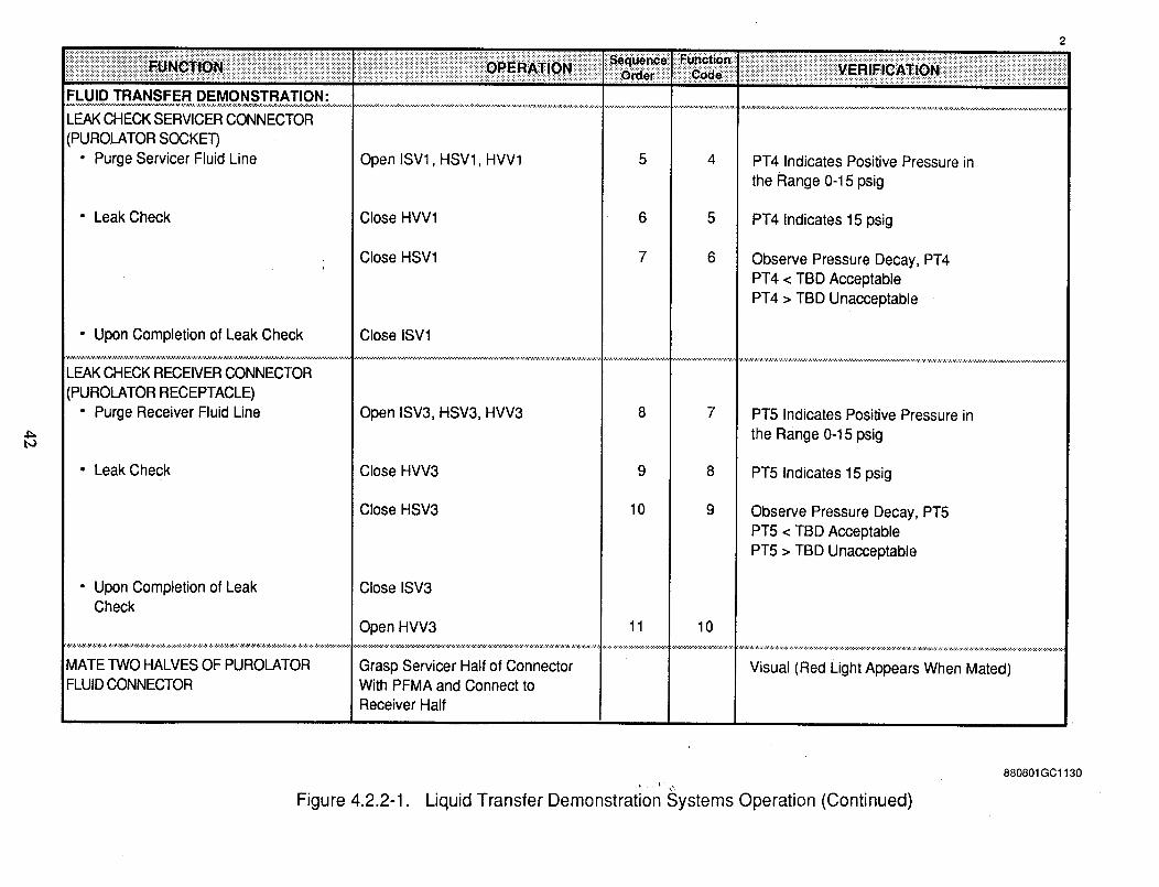
2
_iiiiiiiiiiiiiiiiiiiiiiiiiiiiiiiiiiiiiiiiiiiiiiiiiiiiiiiiiiiiiii!!i!!i_i_!i_iiiiiiiiii!_!_i_i_ii_ii i iiii ii!i! i!i!ii!i iil i ii iiiiiiiiiiiiiii!iiiiii!iiiili_!_ii!i!iii!iiii_i!i!i!ili!ii_i_i_i_iiiii!iiii_n_ Jilil_u_ib_iii iiiiii!_ii!!i!_!i_i!i_i_ii_iii_!iii!!ii!_!_!!!!!_!_!_!_iiiiii!i!_i_!_iiiii_i_i_iii_!iiiiiiii_ i
FLUID TRANSFER DEMONSTRATION:
LEAK CHECK SERVICER CONNECTOR
(PUROLATOR SOCKET)• Purge Servicer Fluid Line
• Leak Check
• Upon Completion of Leak Check
LEAK CHECK RECEIVER CONNECTOR
(PUROLATOR RECEPTACLE)• Purge Receiver Fluid Line
• Leak Check
• Upon Completion of LeakCheck
MATE TWO HALVES OF PUROLATORFLUID CONNECTOR
Open ISVl, HSV1, HVV1
Close HVV1
Close HSV1
Close ISVl
Open ISV3, HSV3, HVV3
Close HVV3
Close HSV3
Close ISV3
Open HVV3
Grasp Servicer Half of ConnectorWith PFMA and Connect toReceiver Half
4
5
6
PT4 Indicates Positive Pressure in
the Range 0-15 psig
PT4 Indicates 15 psig
Observe Pressure Decay, PT4PT4 < TBD Acceptable
PT4 > TBD Unacceptable
78
9
10
1011
PT5 Indicates Positive Pressure in
the Range 0-15 psig
PT5 Indicates 15 psig
Observe Pressure Decay, PT5PT5 < TBD AcceptablePT5 > TBD Unacceptable
Visual (Red Light Appears When Mated)
880801GC1130
Figure 4.2.2-1 Liquid Transfer Demonstration Systems Operation (Continued)
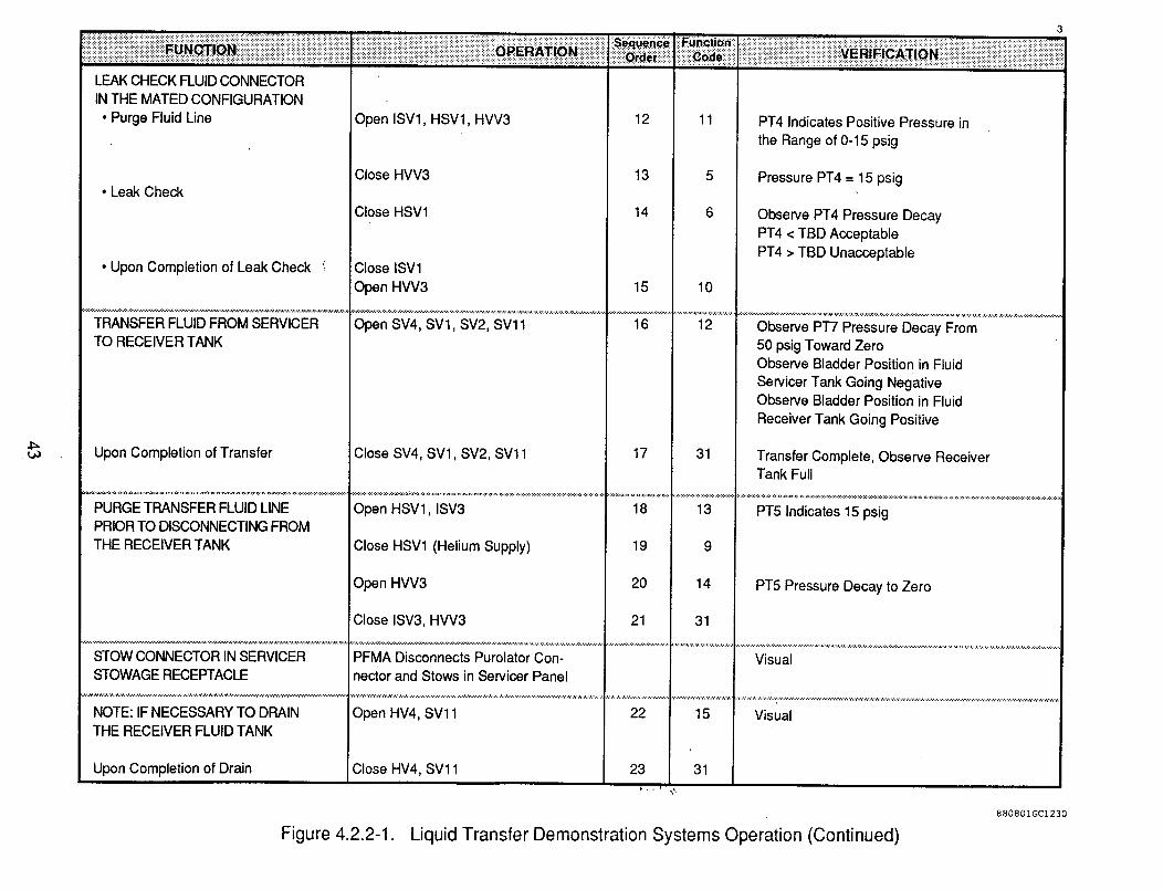
4_
! !! i!!! !! ! i i ii!ii iiiiiiiiiiiiiiiiiiiii!i!i!i i iiiiiiiiiiiiiiiiiiiiiiii!! i!iiiiiiiiiiiiiiiiiiiiiiii!iiiiiiiliiiiiiiiiiiiiiiiiiiiiii!ili!iliiiiiiiiiiiiiiii E i iiiiiiiiii
LEAKCHECK FLUIDCONNECTORINTHE MATED CONFIGURATION
• Purge Fluid Line Open ISVl, HSVl, HVV3 12
• Leak Check
• Upon Completion of Leak Check i
TRANSFER FLUID FROM SERVICERTO RECEIVER TANK
Upon Completion of Transfer
PURGETRANSFER FLUID LINEPRIORTO DISCONNECTINGFROMTHE RECEIVER TANK
STOWCONNECTOR INSERVICERSTOWAGERECEPTACLE
NOTE: IF NECESSARY TO DRAINTHE RECEIVER FLUID TANK
Upon Completion of Drain
Close HVV3
Close HSV1
Close ISV1
Open HVV3
Open SV4, SVl, SV2, SV11
Close SV4, SVl, SV2, SVl 1
Open HSV1, ISV3
Close HSV1 (Helium Supply)
13
14
15
16
17
18
19
Open HVV3
Close ISV3, HVV3
20
21
ii!iiiiiiiiiiiiiiii!iiii!!ii! iiiiiiiiii!iiiiiiiiiiiiiiiiii E! i i iiii iiiiiiiiiiiiii ii i!iiiiiiiiiiiiii!iiiiiiiiiiiiiiiiiiiiii iii iiiiiiiiii i
11
10
12
31
PT4 Indicates Positive Pressure in
the Range of 0-15 psig
Pressure PT4 = 15 psig
Observe PT4 Pressure DecayPT4 < TBD AcceptablePT4 > TBD Unacceptable
Observe PT7 Pressure Decay From50 psig Toward ZeroObserve Bladder Position in Fluid
Servicer Tank Going NegativeObserve Bladder Position in Fluid
Receiver Tank Going Positive
Transfer Complete, Observe ReceiverTank Full
13
9
14
31
PT5 Indicates 15 psig
PT5 Pressure Decay to Zero
PFMA Disconnects Purolator Con- Visualnector and Stows in Servicer Panel
Open HV4, SV11 22 15 Visual
Close HV4, SV11 23 31
880801GC1230
Figure 422-1 Liquid Transfer Demonstration Systems Operation (Continued)
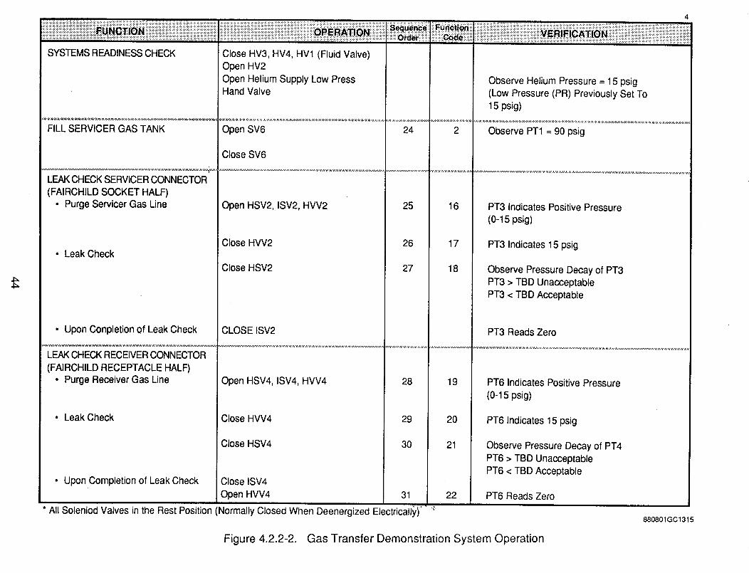
4
!_i_i:i_i:i_ili_i_i_i_i_i!i_i_i!i!i!i!i!i!i:i!i!i!!..................:_:i_i_i_i_i:i:!:!i!:_:_:iii_i_i:i_i:i:i:!:i_i:_:i_!i_:!:_:_:_:_:!:i:i:i:i:!:i:i_i:i:!:!:!:_!_!_!_!_:_:_:_:_:_:_:_:_:_:_i_:_:i:i:i:_:i:iii:i:i:i:i:i:i:!:i:i:i:i:!:_:_:_:_:_:_:_i_:_:i:i:i:i:!:!:_:_:_:_:i:_:i_i_i:i:i:_:_:_:_:_:_:_:i:_:_:i:i:i:i:!:i:i:!:i_i:!:!:_:!:_:_:_:_:_:i:i:i:_:_.: ::i:i:i:i:i:i:_:_i:!:!:i__i...........i:i:i:i:!:: :: i : _:i:_:_:i:i:!:i_:i:!:i_i:i:!:_i:!:::::i:i:i:::::::_:::::::::::::::::::::::::::: :::_::_ili!ii!i!:!:i:ii_ii!!i_ii_!i!i!!_i i
SYSTEMS READINESS CHECK
FILL SERVICER GAS TANK
Close HV3, HV4, HV1 (Fluid Valve)Open HV2Open Helium Supply Low PressHand Valve
Open SV6
Close SV6
24 2
LEAK CHECK SERVICER CONNECTOR
(FAIRCHILD SOCKET HALF)
• Purge Servicer Gas Line Open HSV2, ISV2, HVV2 25 16
Close HVV2 26 17• Leak Check
Close HSV2 27 18
• Upon Conpletion of Leak Check
LEAK CHECK RECEIVER CONNECTOR
(FAIRCHILD RECEPTACLE HALF)• Purge Receiver Gas Line Open HSV4, ISV4, HVV4 28
• Leak Check Close HVV4 29 20
Close HSV4 30 21
• Upon Completion of Leak Check Close ISV4
Open HVV4 31 22
* All Soleniod Valves in the Rest Position (Normally Closed When Deenergized Electricall_,i' '"
Observe Helium Pressure = 15 psig(Low Pressure (PR) Previously Set To15 psig)
Observe PT1 = 90 psig
PT3 Indicates Positive Pressure
(0-15 psig)
PT3 Indicates 15 psig
Observe Pressure Decay of PT3PT3 > TBD Unacceptable
PT3 < TBD Acceptable
CLOSE ISV2 PT3 Reads Zero
19 PT6 Indicates Positive Pressure
(0-15 psig)
PT6 Indicates 15 psig
Observe Pressure Decay of PT4
PT6 > TBD UnacceptablePT6 < TBD Acceptable
PT6 Reads Zero
880801GC1315
Figure 4.2.2-2. Gas Transfer Demonstration System Operation
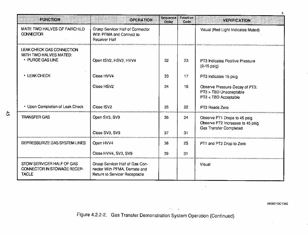
L_
MATE TWO HALVES OF FAIRCHILDCONNECTOR
LEAK CHECK GAS CONNECTION
WITH TWO HALVES MATED:• PURGE GAS LINE
• LEAK CHECK
• Upon Completion of Leak Check
TRANSFER GAS
Grasp Servicer Half of ConnectorWith PFMA and Connect toReceiver Half
Open ISV2, HSV2, HVV4
Close HVV4
Close HSV2
Close ISV2
Open SV3, SV9
Close SV3, SV9
32
33
34
35
36
37
23
17
18
22
24
31
5
i i i iii i i iiiiiiiiiiiiiiiiiiii iiiiiii i i i iii i iii i i E ! i iiiiiiiiiii i iiiiiiiiiiiiiiiiii iiiiiiiiiiiiiiiiiiiii i i iii i i i i i i iiiiii
Visual (Red Light Indicates Mated)
PT3 Indicates Positive Pressure
(0-15 psig)
PT3 Indicates 15 psig
Observe Pressure Decay of PT3:PT3 > TBD UnacceptablePT3 < TBD Acceptable
PT3 Reads Zero
Observe PT1 Drops to 45 psigObserve PT2 Increases to 45 psigGas Transfer Completed
DEPRESSURIZE GAS SYSTEM LINES
STOW SERVICER HALF OF GASCONNECTOR IN STOWAGE RECEP-
TACLE
Open HVV4
Close HVV4, SV3, SV9
Grasp Servicer Half of Gas Con-nector With PFMA, Demate and
Return to Servicer Receptacle
38 25 PT1 and PT2 Drop to Zero
39 31
Visual
Figure 4.2.2-2. Gas Transfer Demonstration System Operation (Continued)
8808O1GC 1340
TR90-89
position coordinates of the PFMA's end effort relative to the receiving connectors. Figure 4.3-1
shows the format for providing operator skill evaluation data related to performing tasks, with the
PFMA, which are required to conduct a fluid transfer operation with the remote fluid transfer
demonstrator. Operator tasks not requiring the PFMA such as loading the fluid transfer tanks,
initial leak checks etc., are not included in the task evaluations because they do not require skill in
operating the PFMA.
Following each test series, the data will be reduced to allow completing the skill evaluation
forms, as shown in Figure 4.3-1. Additional tabular or graphical data that is needed to identify
anomalies and/or problems that may influence subsequent runs can be provided. A test report can
be prepared at the completion of the test program to document the significant overall results and
conclusions.
_k
46
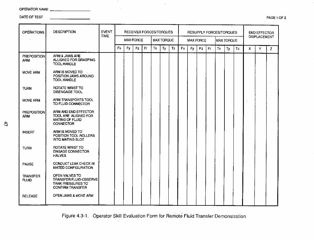
OPERATOR NAME
DATE OF TEST PAGE 1 OF 2
4_
OPERATIONS
PREPOSITIONARM
MOVE ARM
TURN
MOVE ARM
PREPOSITIONARM
INSERT
TURN
PAUSE
TRANSFERFLUID
RELEASE
DESCRIPTION
ARM & JAWS AREALLIGNED FOR GRASPINGTOOL HANDLE
ARM IS MOVED TOPOSITION JAWS AROUNDTOOL HANDLE
ROTATE WRIST TODISENGAGE TOOL
ARM TRANSPORTS TOOLTO FLUID CONNECTOR
ARM AND END EFFECTORTOOL ARE ALIGNED FORMATING OF FLUIDCONNECTOR
ARM IS MOVED TOPOSITION TOOL ROLLERSINTO MATING SLOT
ROTATE WRISTTOENGAGECONNECTORHALVES
CONDUCT LEAK CHECK INMATED CONFIGURATION
OPEN VALVESTOTRANSFER FLUID-OBSERVETANK PRESSURESTOCONFIRM TRANSFER
OPEN JAWS & MOVE ARM
EVENTTIME
RECEIVER FORCESFI'ORQUES RESUPPLY FORCES,q-ORQUES
MAX FORCE MAXTORQUE MAX FORCE MAX TORQUE
Fx Fy Fz Fr Tx Ty Tz Fx Fy Fz Fr Tx Ty Tz
END EFFECTORDISPLACEMENT
X Y Z
Figure 4.3-1. Operator Skill Evaluation Form for Remote Fluid Transfer Demonstration
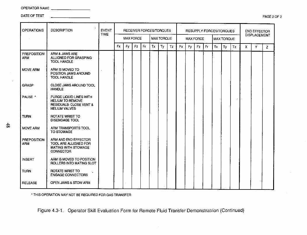
OPERATOR NAME
DATE OF TEST PAGE 2 OF 2
oo
OPERATIONS
PREPOSITIONARM
MOVE ARM
GRASP
PAUSE *
TURN
MOVE ARM
PREPOSITIONARM
INSERT
TURN
RELEASE
DESCRIPTION
ARM & JAWS AREALLIGNED FOR GRASPINGTOOL HANDLE
ARM IS MOVED TOPOSITION JAWS AROUNDTOOL HANDLE
CLOSE JAWS AROUND TOOLHANDLE
PURGE LIQUID LINES WITHHELIUM TO REMOVERESIDUALS- CLOSE VENT &HELIUM VALVES
ROTATE WRIST TODISENGAGE TOOL
ARM TRANSPORTS TOOLTO STOWAGE
ARM AND END EFFECTORTOOLAREALLIGNED FORMATING W_H STOWAGECONNECTOR
ARM IS MOVED TO POSITIONROLLERS INTO MATING SLOT
ROTATE WRISTTOENGAGECONNECTORS
OPEN JAWS & STOW ARM
EVENT.TIME
RECEIVER FORCES/TORQUES
MAX FORCE MAXTORQUE
Fx Fy Fz Fr Tx Ty Tz Fx
RESUPPLY FORCES/TORQUES
MAX FORCE MAX TORQUE
Fy Fz Fr Tx Ty Tz
END EFFECTORDISPLACEMENT
X Y Z
* THIS OPERATION MAY NOT BE REQUIRED FOR GAS TRANSFER
Figure 4.3-1. Operator Skill Evaluation Form for Remote Fluid Transfer Demonstratrion (Continued)
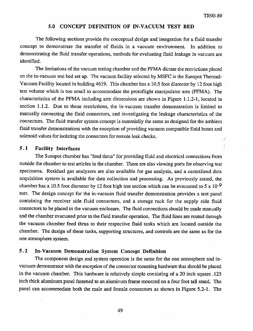
5.0 CONCEPT DEFINITION OF IN-VACUUM TEST BED
TR90-89
The following sections provide the conceptual design and integration for a fluid transfer
concept to demonstrate the transfer of fluids in a vacuum environment. In addition to
demonstrating the fluid transfer operations, methods for evaluating fluid leakage in vacuum are
identified.
The limitations of the vacuum testing chamber and the PFMA dictate the restrictions placed
on the in-vacuum test bed set up. The vacuum facility selected by MSFC is the Sunspot Thermal-
Vacuum Facility located in building 4619. This chamber has a 10.5 foot diameter by 12 foot high
test volume which is too small to accommodate the protoflight manipulator arm (PFMA). The
characteristics of the PFMA including arm dimensions are shown in Figure 1.1.2-1, located in
section 1.1.2. Due to these restrictions, the in-vacuum transfer demonstration is limited to
manually connecting the fluid connectors, and invesiigating the leakage characteristics of the
connectors. The fluid transfer system concept is essentially the same as designed for the ambient
fluid transfer demonstrations with the exception of providing vacuum compatible fluid hoses and
solenoid values for isolating the connectors for remote leak checks.
5.1 Facility Interfaces
The Sunspot chamber has "feed thrus" for providing fluid and electrical connections from
outside the chamber to test articles in the chamber. There are also viewing ports for observing test
specimens. Residual gas analyzers are also available for gas analysis, and a centralized data
acquisition system is available for data collection and processing. As previously stated, the
chamber has a 10.5 foot diameter by 12 foot high test section which can be evacuated to 5 x 10 -9
torr. The design concept for the in-vacuum fluid transfer demonstration provides a test panel
containing the receiver side fluid connectors, and a storage rack for the supply side fluid
connectors to be placed in the vacuum enclosure. The fluid connections should be made manually
and the chamber evacuated prior to the fluid transfer operation. The fluid lines are routed through
the vacuum chamber feed thrus to their respective fluid tanks which are located outside the
chamber. The design of these tanks, supporting structures, and controls are the same as for the
one atmosphere system.
5.2 In-Vacuum Demonstration System Concept Definition
The component design and system operation is the same for the one atmosphere and in-
vacuum demonstrator with the exception of the connector mounting hardware that should be placed
in the vacuum chamber. This hardware is relatively simple consisting of a 20 inch square .125
inch thick aluminum panel fastened to an aluminum frame mounted on a four foot tall stand. The
panel can accommodate both the male and female connectors as shown in Figure 5.2-1. The
49
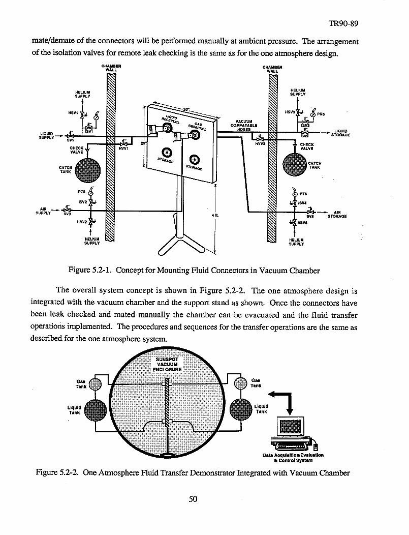
TR90-89
mate/demateof theconnectorswill beperformedmanuallyat ambientpressure.The arrangement
of the isolationvalvesfor remoteleakcheckingis thesameasfor theoneatmospheredesign.
CHAMBER CHAMBERWALL WALL
HELIUMHELIUM SUPPLYSUPPLY
1 ;HSVI
LIQUIDSUPPLY
SVl
CHECK,VALVE
CATCHTANK
HWl
VACUUMCOMPATABLE
HOSES
HVV3 CHECKVALVE
CATCH
STOR4QE TANK
PR8
UQUID
AIRSUPPLY
PT3
SV3
HSV2
tHELIUMSUPPLY
PT6
ISV4
AIR4 ft. SV9 STORAGE
HSV4
HELIUMSUPPLY
Figure 5.2-1. Concept for Mounting Fluid Connectors in Vacuum Chamber
The overall system concept is shown in Figure 5.2-2. The one atmosphere design is
integrated with the vacuum chamber and the support stand as shown. Once the connectors have
been leak checked and mated manually the chamber can be evacuated and the fluid transfer
operations implemented. The procedures and sequences for the transfer operations are the same as
described for the one atmosphere system.
.... )iiiiiiiii ,....
T )!!!)!!!)))) !))))!)) I,U.IDita Aequlsttlon/EvMustlon
& Control System
Figure 5.2-2. One Atmosphere Fluid Transfer Demonstrator Integrated with Vacuum Chamber
50
TR90-89
5.3 In-Vacuum Fluid Connectors Leak Check
The minimization of leaks or spills is accomplished by leak checks of both the fluid supply
and receiving connectors in the demated and mated configuration prior to the transfer of fluid.
Subsequent to fluid transfer the liquid lines are purged with hefium before disconnecting to prevent
potential liquid spills. In demonstrating this approach in vacuum, the connectors should first be
leak checked in the disconnected configuration with the chamber evacuated. After this check the
chamber should be brought to one atmosphere and the connectors manually connected. The
chamber should be evacuated and, in this configuration, the connector volumes isolated and
pressurized with helium. Leakage can be determined by the pressure decay rate, as described in
Section 2.2.3. After verification of the leak checks the fluid should be transferred as in the one
atmosphere fluid transfer demonstrator.
To eliminate possible spills at disconnect, the connector and line should be purged before
demating with helium. The residuals should be collected in a container outside the vacuum
chamber. After this operation the chamber should be brought up to atmospheric pressure and the
fluid lines manually disconnected and stowed. Any significant leakage that might occur during
fluid transfer can be detected by the facility gas analyzer.
51
6.0 REFERENCES
TR90-89
.
o
3.
"1978 Extruding and Molding Grades", The International Plastics Selector, Inc., CorduraPublications, Inc.
Machine Design, March 17, 1977, pp. 112-113.
Ugural, A. C., S. K. Fenster, "Advanced Strength and Applied Elasticity", ElsevierScience Publishing, 1987.
52
TR90-89
APPENDIX A
Certification Documentation for the Air Tank Spheres
53
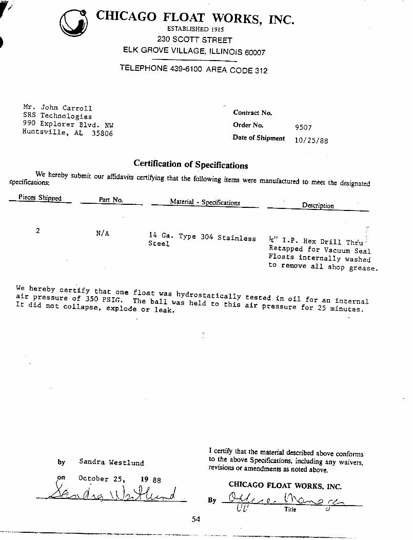
CHICAGO FLOAT WORKS, INC.ESTABLISHED 1915
230 SCOTT STREET
ELK GROVE VILLAGE, ILLINOIS 60007
TELEPHONE 439-6100 AREA CODE 312
Hr. John Carroll
SRS Technologies Contract No.
990 Explorer Blvd. NW Order No. 9507
Huntsville, AL 35806 DateofShipment 10/25/88
Certification of Specifications
We hereby submit our affidavits certifying that the following items were manufactured to meet the designated_pec/fications:
PiecesShipped PartNo.Material - Specifications
Description
2 N/A14 Ga. Type 304 StainlessSteel ¼" I.P. Hex Drill Thfu_
Retapped for Vacuum Seal
Floats internally washed
to remove all shop grease.
We hereby certify that one float was hydrostatically tested in oil for an internal
air pressure of 350 PSIG. The ball was held to this air pressure for 25 minutes.It did not collapse, explode or leak.
by Sandra Westlund
on October 25, 19 88
I
.54
I certify that the material described above conforms
to the above Specifications, including any waivers,revisions or amendments as noted above.
By
CHICAGO FLOAT WORKS, INC.
UU / .... Title :-) "

TR90-89
APPENDIX B
System Hardware Mechanical Drawings
55
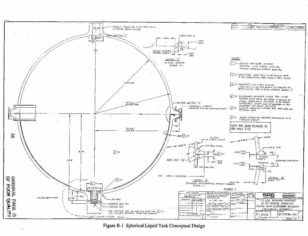
/"
//
I
...----',_SEE DET.41L 'A _
_E,_D_U/_ V._RMD
COU_L_ o C_Z M_. MV B_I,_ TZ1876 T
\
__J
/" _ t =.a_ (_/_e)_' .-_ 75 RAD. TYP KE._L
.SEE DE'Z-'_ VII L ?,_-+.ooo
WOT_
_OF_Y _AJ_,. .5_E O-Rlld_ GROOVE Z2_rA_I/_ I_
D>
CDR/JER ,#2'._DIUS.
I COPY HAS BEEN REDUCEDTO 1ONE-HALF SIZE
0#2 R. Ty)R
" _-.ooz-71 "-] !
/ DETRIL '_"
FIGUEE 2
-- ,o=_.*Nc_= *._ .,c-~o . m_D_.B95.?ODO
___, ,: I_. 5D* ZM_IDE DIAME TE_
Figure B-1 Spherical Liquid Tank Conceptual Design
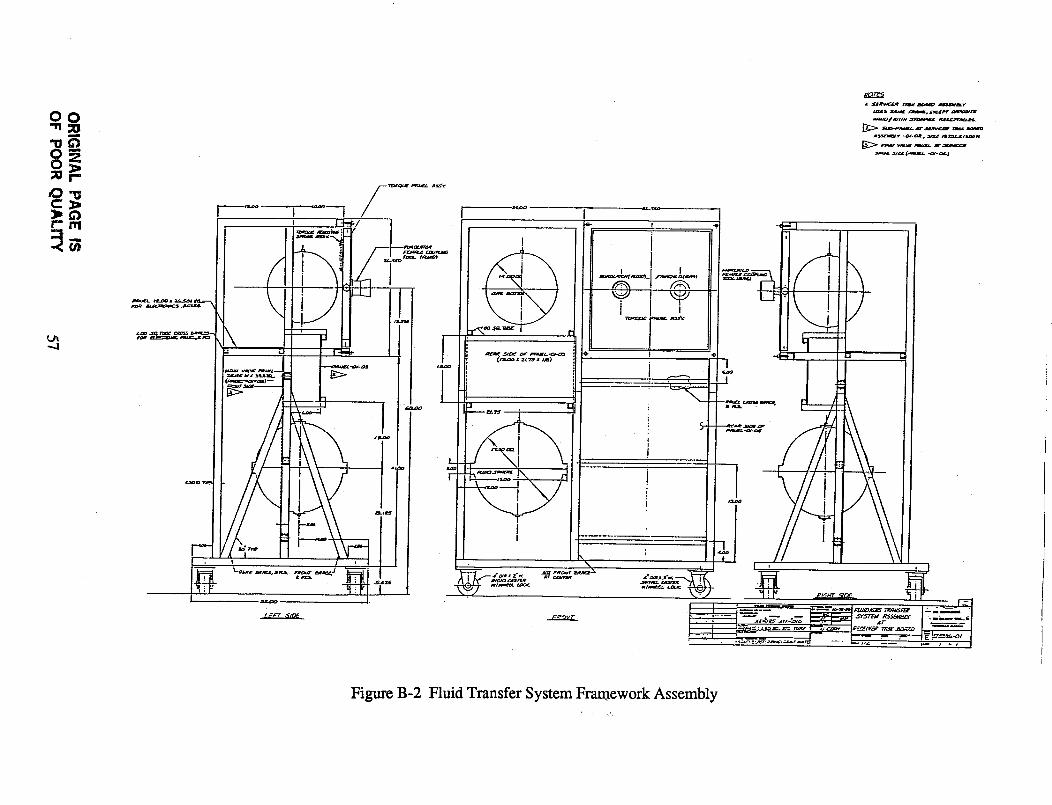
OOm
_Qt-rq
-.,.i
L _Jrv_ rAsr _ _m_a_v
Figure B-2 Fluid Transfer System Framework Assembly
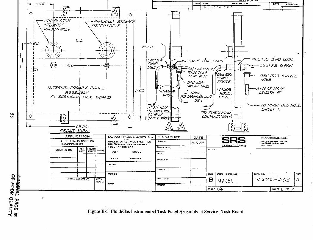
L
F-
"O
n_-'l I _ l I I I,_I__>-s5,,I I IU_l j_ _ _-._ .... z-.__ ' '
] \_TO_VtT&E X RF__EPPITCLF ' , _ II I
i F ?EC_PT, qcL £__ "',k \-1 , I Ill
--,- m -- -T- I I o_5 _'/voI E i ___ 51#/VEL - " " ' _ 5 7..... C. _ .......... r .._ 21XL3 EY_LgD_I
"I ' ' ' W/SD71X4
' i ',//I III _4_-_ IW_ ii Iii '_
I ', I I _ '9.. 5_ z j I! !: I , / I I--Y, I/ ..,__ 11 <----- ;-o _,_,U,Fm_,_o._,
...... L....L___ / __ l'rD,_,qmC#/_lI <T,PPLIRDL,,gTD, q I_ "..... . _uPuu_ ', __-.
-_ _ _,OO _- _ _ _ r-_ "
APPLICATION
THIS ITEM IS USED ON
SUBASSEMBLIES
DRAWING NO.
FINAL ASSEMBLY
TOTAL
tOTAL
REQ'D.
DO NOT SCALE DRAWING
UNLESS OTHERWISE SPECIFIED
DIMENSIONS ARE IN INCHES.
TOLERANCES ARE:
.XX - .XXXX -
.XXX - ANGLE_ -
TREAT_.[xT
sIGNATURE
O_A_lt Iv
RRO,J[CI [RO._.
EI_'R.
APPROVEDBY
APPROVED BT
SUBMITTED BY
DIRECTOR
TITLE
SRSTECMNOLOGIES
ST$_MS TECHN_COGT O_S_
S$$$p_RK_ C_r_ S_TE i*¢JNTSV_UE. _8_ 3S_S
I_O_l IO0_TS
s,_IcoDE,OEN_.NO.IB19V959,'V--ALE.//4-
OWG."O. IR_V.I
Figure B-3 Fluid/Gas Instrumented Task Panel Assembly at Servicer Task Board
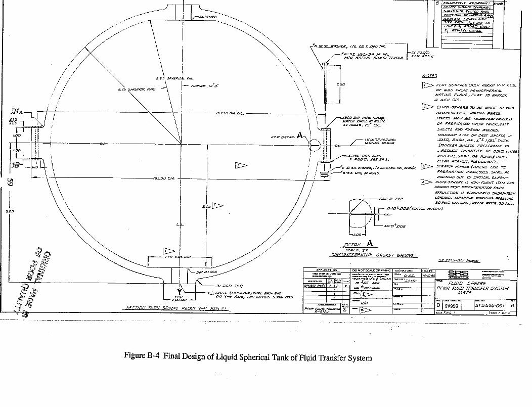
FigureB-4 Final Design of Liquid Spherical Tank of F10id Transfer System
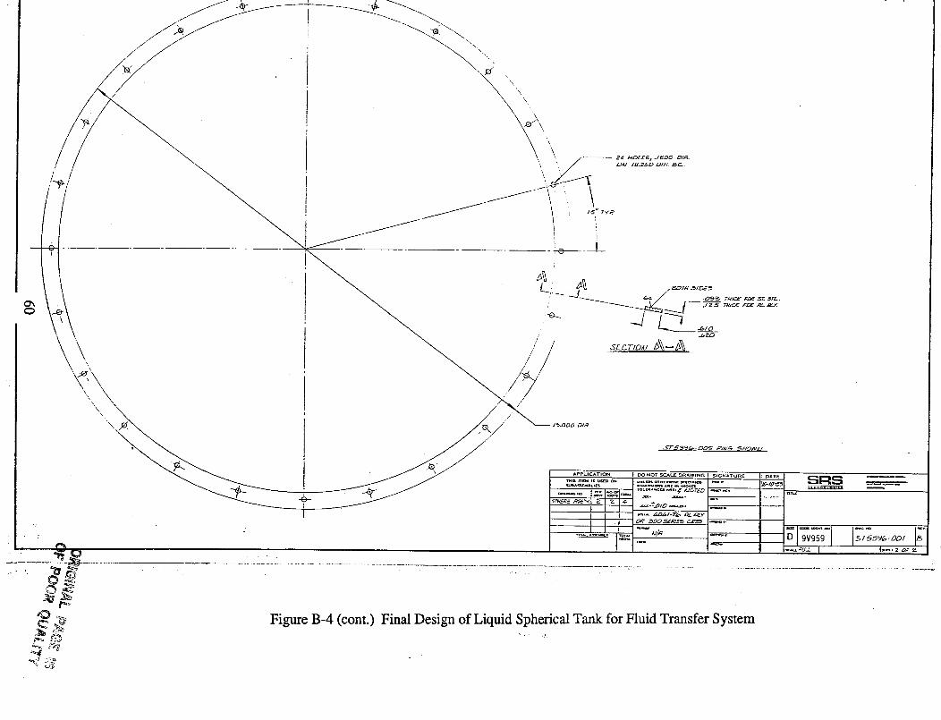
i A,-
//
"_. /",
'\ /
r. • :.
' D_
..3-TS_?C_,-DZ)G- PI4/_ S.'¢0_/,/
" i I/ 1 _.-*_o,o_. I_"
Figure B-4 (cont.) Final Design of Liquid Spherical Tank for Fluid Transfer System,,. .,,,
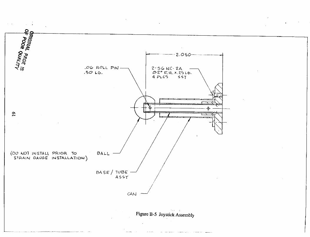
.i
e_
2.050
Ox
(00 k/07 I_JSTALL PRIOP. "To
S_I_AI_4 GAUGE= IkJS'fALLA'iIOk])
CA_J
//..
_/
• Figure B-5 Joystick Assembly
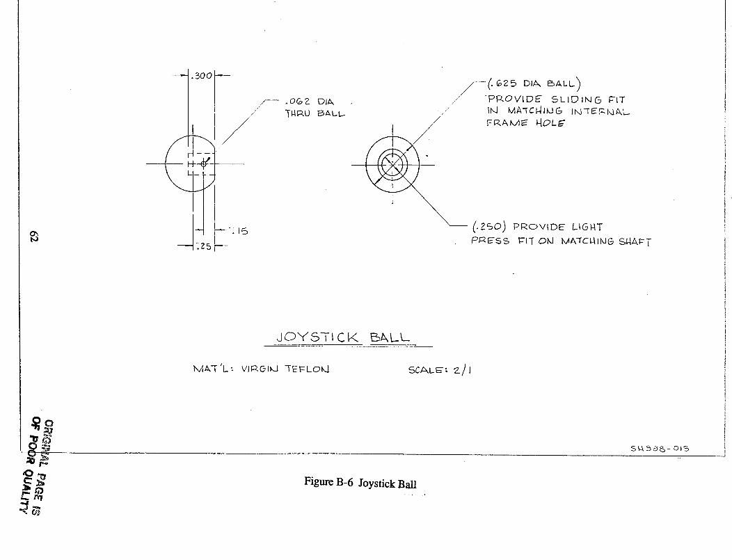
ba
//'" -n4p,u
/
I
.5 _
-" -PROVIDE SLIDING FIT
" II'd MA"fCI--JlIdC_ I_q'_'_|,4A, L...i
F_AM_ _OL_"/
('. Z_O) PROVIDE LIGNT
/DRESS _lq" Ok] MA'TCI41MG SNAI:- T
d OY Si- I C V,. _/kL..L...
l,v|&q" 'L : Vll:::zO_kJ -TEFLOk.I SCALE': _.) I
_2
S',-k 38_- o_%
,OFigure B-6 Joystick Ball
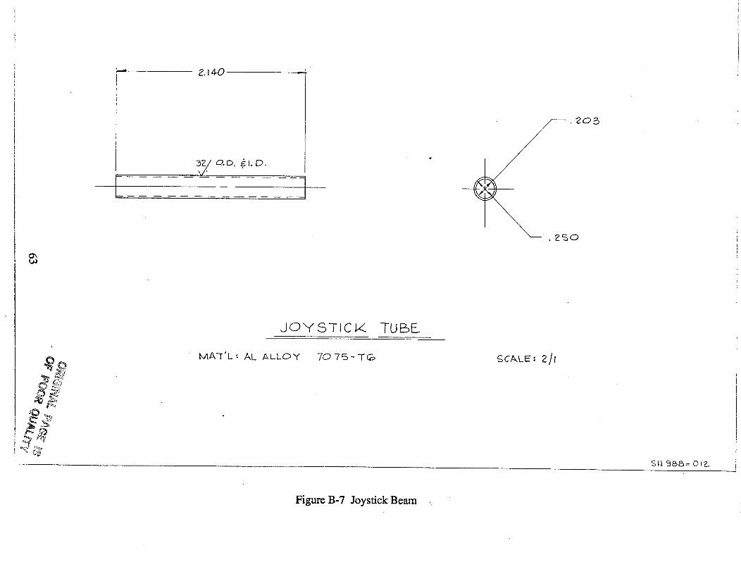
8
!ii
tt
2.140
JO"Y" STI C1/. TUBE
MA-r'L: AL ALLOY 70 75- TG:, gCALE : 2/I
$¼ 98,&= 012..
Figure B-7 Joystick Beam ,:
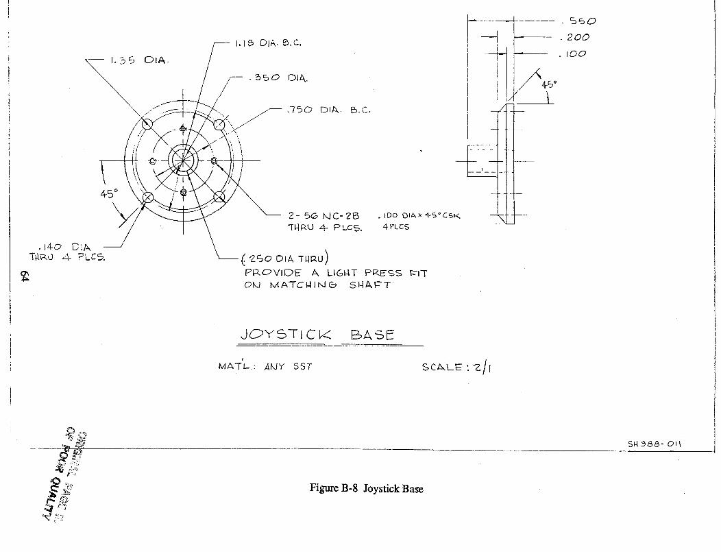
• 200
• too
JCPYS-]- IC I/_ ESAS_
s
MA'T L." ,4_JY SST SCA, LE ' G_/I
SIt B&O- OI
Figure B-8 Joystick Base
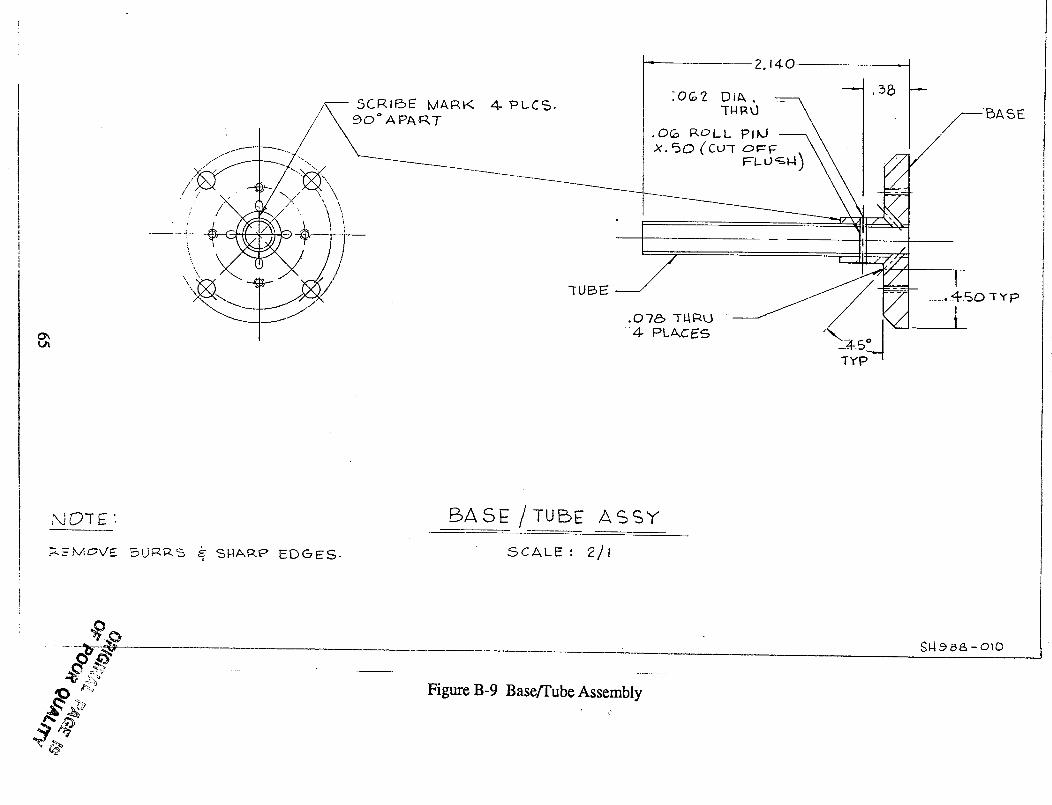
I
SCR 11::SE'MARK
//_ " \ X
4 PcC%.
;R_o-r E '
.:. _" JXAOx/E _ SI4AR_ EDGES-
BASE /TUBE ASSY
SCALE : z/J
£J4.9 a,& - OlD
Figure B-9 Base/Tube Assembly
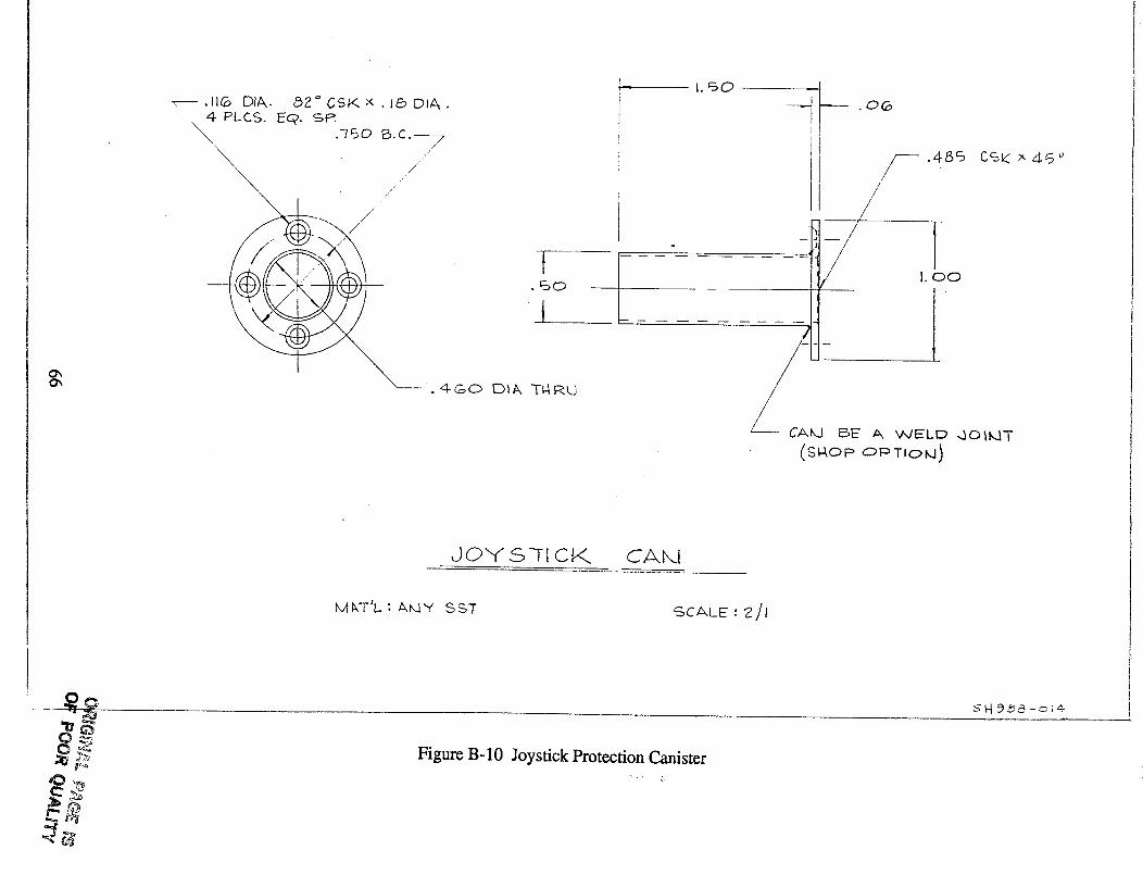
-- _116 DI&.
4- PLCS.\\
\,
&2 ° C;SK x . l& DIA.E@. se.
.q6o B.c.--- 7
//
t
I
• 4@0 [)l& T_k;
I
.o6
---.486 CS_ x46 °
/
I. oo
/L ca_ _e _ wELD 4O_T
(SI40P OPTIC>M)
JOYS]I CK CA_I
MKT'L. : &MY SSTSC_,LE : "2/1
....Figure B-IO Joystick Protection Canister
4D,,_• ,, ,_.
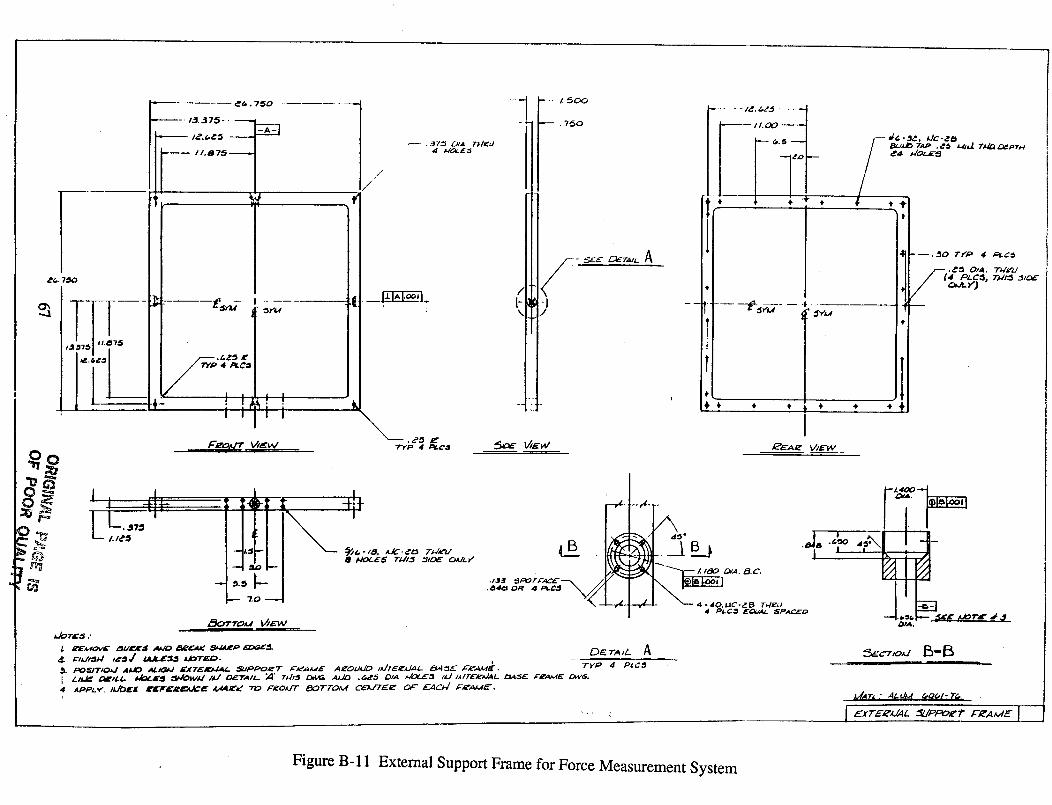
_'_ _(*. 7_0
.... i ....
tl.87_
II
I
I :_Y44
| i I
! !A_.I iI '1' I
//"/
---- ._7-_ DtA Tl.l_d
_
-I ---f _- --
- - 1£. _.,Z._, ----II
//.0_ -'---I
/"'""; * " * 1 "+l
--.,_0 Tr'* o 4 a¢_
(4 .DLC:_, TI#I:_ 3_DE
C_-r')
.it -
IllI t 41_
k I_.,,, "i"I/_':I
i i. i
-"'t1.:11"-
--1 ._ I--
@ t4oL_,@ TAt/,ff __lD_ o.vi.K
/ ,_.._ "3PO r F_,CE ---_ /
__
--,L;--#-
_ _D/.4. _.C.
OIA.
i
I_AT_. .' ALUM &O(,/- TG
I ExTE_'/JAL __JPPO,_f" _'I_AME I
Figure B-11 External Support Frame for Force Measurement System
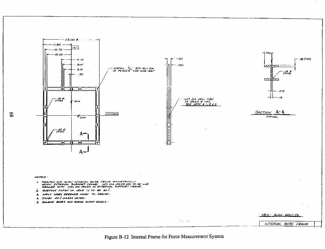
oo
I0. 7_
_10. O0
_ I F-/5°
JI
li
_,z_E Z/OTC ._ / l _ ft j
.75C_ ./a ¢T'/P)
[2S_, _ ...... 7_[
_-- ./_
IZ_ & t T"r'R;
_ .075_.1._,
"r¥'P/cA/-
Figure B-12 Internal Frame for Force Measurement System
............... J.
A./A TL ." _lJ._J (/Of_, I - T(._
IAJTE, E'AZ-,4L ,_zl..,,RE ,L'-._'AAdE
TR90-89
APPENDIX C
External Electrical Configuration for theSolenoid Valve Logic Controller
69
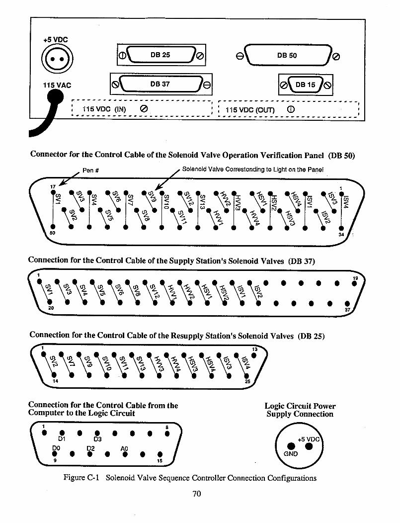
+5 VDC
115 VAC
DB 25
fd
, _SVDC(0N) Q ' ', , _SVDC(OUT) (])
Connector for the Control Cable of the Solenoid Valve Operation Verification Panel (DB 50)
Pen # Solenoid Valve Correstondingto Lighton the Panel
1
34
Connection for the Control Cable of the Supply Station's Solenoid Valves (DB 37)
Connection for the Control Cable of the Resupply Station's Solenoid Valves (DB 25)
Connection for the Control Cable from the
Computer to the Logic Circuit
=)D D
• • • o _ o o
Figure C- 1
Logic Circuit PowerSupply Connection
Solenoid Valve Sequence Controller Connection Configurations
70


![Orbit type: Sun Synchronous Orbit ] Orbit height: …...Orbit type: Sun Synchronous Orbit ] PSLV - C37 Orbit height: 505km Orbit inclination: 97.46 degree Orbit period: 94.72 min ISL](https://img.pdfslide.net/doc/110x75/5f781053e671b364921403bc/orbit-type-sun-synchronous-orbit-orbit-height-orbit-type-sun-synchronous.jpg)