Embed Size (px)
Citation preview

SS -34AS
Four-Channel Signal Trim Junction BoxFM US and Canadian Approved
The SS-34AS Junction Box can accommodate up to four load cells. Load cell output is trimmed withpotentiometers individually. Signal Trim range is 100k potentiometer at 25 turn increments.
MOUNTING OF THE JUNC TION BOX ENCLOSURE
1
INSTALLATION MANUAL
Mount the SS-34AS in a location convenient for servicing. Try to mount the enclosure in a location that will not require extending the load cell cables. Environmental conditions should also be considered.Mount the enclosure using four pan-head screws, bolts, or masonry fasteners.
Grounding Lugfor SurgeSuppression

Coti Global Sensors | 1 .866.762.2684 | w w w.cot iglobal .com | sa les@cot iglobal .com
TRIMMING PROCEDURES
3
Coti Global Sensors manufactures and supplies load cells to companies worldwide. We carry one of the largest selections of load cells available from any manufacturer. Coti Global manufactures all types of load cells, from single point load cells to double ended beams.
We also sell �oor scales, junction boxes, remote displays and other weighing equipment hardware. Our product certi�cations include NTEP, Factory Mutual Approvals, UBC Seismic Approvals and VCAP.
1. Turn the four individual cell potentiometers fully counterclockwise to give maximum signal outputfrom each load cell.
2. Remove all weight from the scale and zero the indicator. Place calibrated test weights over each load cell. The amount of test weights to be used wiill depend on the scale con�guration; for speci�crecommendations, refer to Handbook 44, published by the National Institute of Standards and Technology (NIST). It is recommended to use 25% of scale capacity for a four-cell platform.
3. Record the value displayed on the indicator after the test weight is placed in turn on each corner,directly over the load cell. Allow the scale to return to zero each time to check for friction or othermechanical problems. Select the load cell that has the lowest value as your reference point. This cellwill NOT be trimmed.
4. Place the same test load over each cell in turn. Using the corresponding potentiometer, trim each cell down to equal the reference point. As corner corrections are somewhat interactive, check all cells again for repeatability. If necessary, repeat steps 3 and 4.
5. Tighten the cord grip assemblies and ensure they are watertight. Each cord grip must be tightened so the rubber sleeves begin to protrude from the hub.
6. Unused hubs must be plugged to prevent moisture entry.
7. Insert the enclosed desiccant bag and replace the cover, tightening the cover screws in an alternating pattern to be certain the gasket is compressed equally in all locations.
2
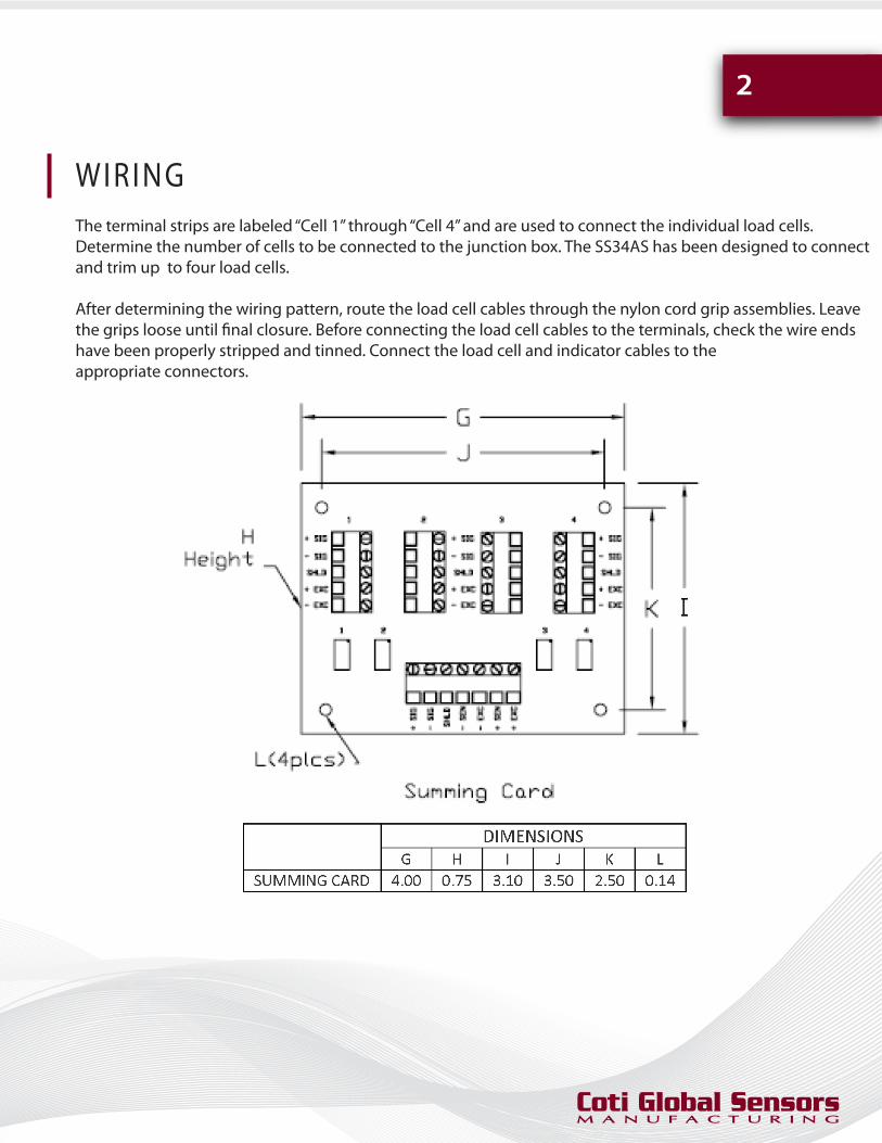
WIRINGThe terminal strips are labeled “Cell 1” through “Cell 4” and are used to connect the individual load cells.Determine the number of cells to be connected to the junction box. The SS34AS has been designed to connectand trim up to four load cells.
After determining the wiring pattern, route the load cell cables through the nylon cord grip assemblies. Leavethe grips loose until �nal closure. Before connecting the load cell cables to the terminals, check the wire endshave been properly stripped and tinned. Connect the load cell and indicator cables to theappropriate connectors.