Embed Size (px)
Citation preview

PROJE
ADTMF Inlerla Use this project to and decode phone numl,e from the airwaves and display them on your
High Volt Powe
~
It has few parts, but this circuit creates plenty of kilovolts
Wireless Control Build this transmitter/ receiver pair and control almost any electronic device
Gizmo" Robo-LEGO, MiniDisc Recording Wireless Net Access In ,our Poclket? Software, Radio with Bass, and mOI'e'
Also InBid,: • Digital Camcorder and Camera Reviews • Affordable Flat-Panel MonitolS • Hall Effect Sensor Circuits • Scanner Antenna Tips
S'SPECIAL
$5.99 CAN.
AGEANSBACK PUBLICATION 0 •
-LE
...
CUlT
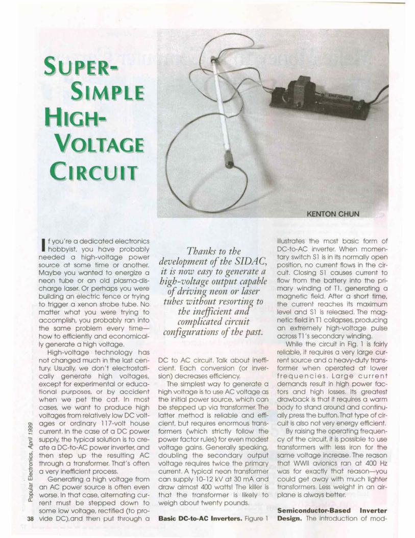
I f you're a dedicated electronics hobbyist, you have probably
needed a high-voltage power source at some time or another. Maybe you wonted to energize a neon tube or an old plasma-discharge laser. Or perhaps you were building an electric fence or trying to trigger a xenon strobe tube. No matter what you were trying to accomplish, you probably ran Into the same problem every timehow to efficiently and economically generate a high voltage.
High-voltage technology has not changed much In the last century. Usually. we don't electrostatlcally generate high voltages, except for experimental or educational purposes, or by accident when we pet the cat. In most cases, we want to produce high voltages from relatively low DC volt-
'" ages or ordinary 117-volt house 5!! ". current. In the case of a DC power 1:; supply, the typical solution Is to cre~ ate a DC-to-AC power inverter, and ti then step up the resulting AC
.~ through a tronsformer. That's often ~ a very Inefficient process. w Generating a high voltage from ~ an AC power source Is often even t worse. In that case, alternating cur-
rent must be stepped down to some low voltage, rectified (to pro-
38 vide DC),and then put through a
Thanks to the development of the SIDAC, it is now easy to generate a high-voltage output capable
of driving neon or lase1~ tubes without resorting to
the inefficimt ana complicated circuit
configtwations of the past.
DC to AC circuit. Talk about Inefficient. Each conversion (or Inversion) decreases efficiency.
The simplest way to generate a high voltage Is to use AC voltage as the initial power source, which can be stepped up via transformer. The latter method is reliable and efficient, but requires enormous transformers (which strictly follow the power factor rules) for even modest voltage gains. Generally speaking, doubling the secondary output voltage requires twice the primary current. A typical neon transformer can supply 10-12 kV at 30 mA and draw almost 400 watts! The killer is that the transformer Is likely to weigh about twenty pounds.
Basic DC-to-AC Inverters. Figure 1
KENTONCHUN
illustrates the most boslc form of DC-to-AC Inverter. When momentary switch S1 Is In Its normally open position, no current flows In the circuit. Closing S1 causes current to flow from Ihe bottery Into the primary winding of Tl , generating a magnetic field . After a short time, the current reaches Its maximum level and S 1 Is released. The magnetic field In Tl collapses, producing an extremely high-voltage pulse across Tl 's secondary winding.
While the circuit In Fig. 1 Is fairly reliable, It requires a very large current source and a heavy-duty transformer when operated at lower frequencies . Large current demands result In high power factors and high losses. Its greatest drawback Is that It requires a warm body to stand around and contlnually press the button. That type of circuit Is also not very energy efficient,
By raising the operating frequency of the circuit, It is possible to use transformers with less Iron for the same voltage increase. The reason that WWII avionics ran at 400 Hz was for exactly that reason-you could get away with much lighter transformers. Less weight in an airplane is always better.
Semiconductor-Based Inverter Design. The Introduction of mod-
S1 T1 HV
~-'---~-~--I --' ~ "' ...
Fig . I. Shown hen is the mOSI bruicform of DCto-AC inverter. 1Vhil~ the circilli is fairly reliable. it requires a very large current sOllrce and a heavy-dllty transformu ..... hen operated at lower freqlleflcits .
ern semiconductors has made It possible to assemble a DC-to-AC Inverter that operates very efficiently. The circuit In Fig. 2 is an example of a basic high-frequency DC-to-AC Inverter. Many of the hlgh-efficiency 12-volt DC to 117-volt AC power Inverters and unlnterruptlble power supply (UPS) designs use a similar configuration as the heart of the circuit.
In the Fig. 2 circuit. an NE555 oscillator/timer (IC1) is set up as a pulse generator. the frequency of which can be set to almost any value. The output of IC1 Is directed through a transformer and stepped up to the required level. The major limitation of the Fig. 2 circuit Is Its output power. The NE555 can directly source up to 200 mW through the transformer. but at the power-supply rail of 9 volts. that's barely enough power to light a tiny neon lamp. Only by adding output switches and a higher supply current can the circuit provide enough power to start a laser or a neon tUbe.
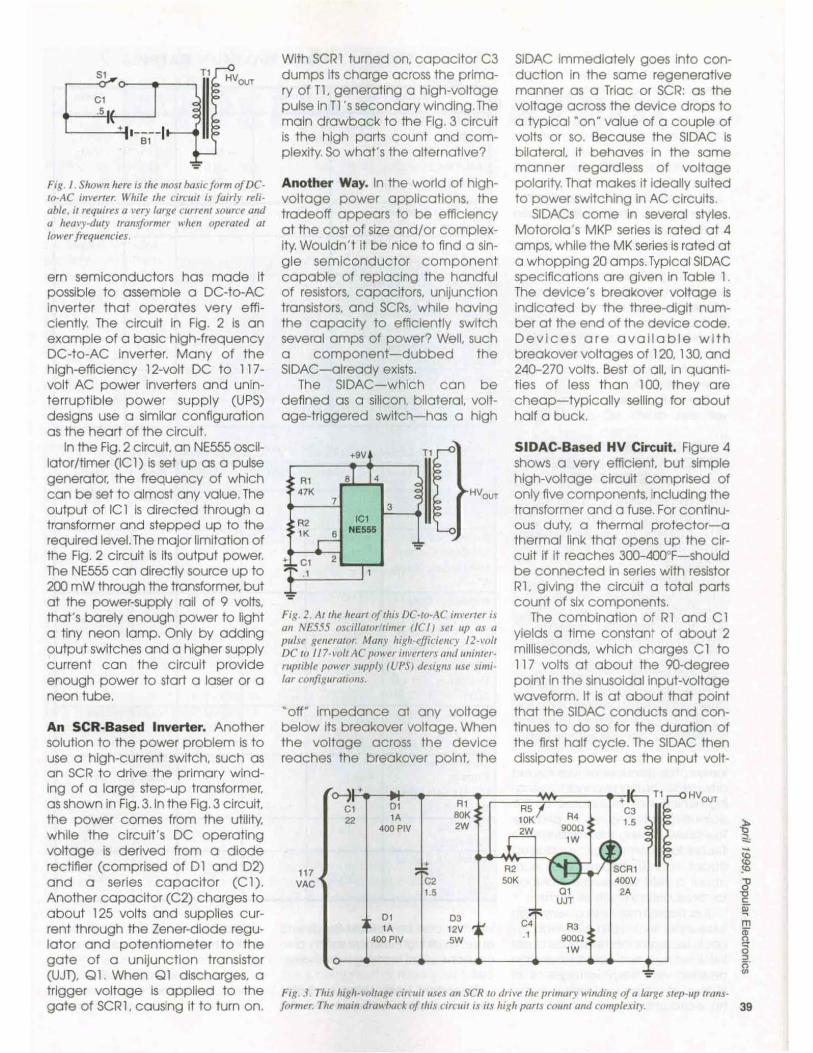
An SCR-Based Inverter. Another solution to the power problem Is to use a high-current switch. such as an SCR to drive the primary windIng of a large step-up transformer. as shown In Fig. 3.ln the Fig. 3 circuit. the power comes from the utility. while the circuit's DC operating voltage is derived from a diode rectifier (comprised of D1 and D2) and a series capacitor (C1). Another capacitor (C2) charges to about 125 volts and supplies current through the Zener-diode regulator and potentiometer to the gate of a unijunctlon transistor (UJT). Q 1. When Q 1 discharges. a trigger voltage Is applied to the gate of SCR1. causing It to turn on.
With SCR1 turned on. capacitor C3 dumps Its charge across the primary of n. generating a high-voltage pulse In Tl 's secondary winding. The main drawback to the Fig . 3 circuit is the high parts count and complexity. So what's the alternative?
Another Way. In the world of hlghvoltage power applications. the tradeoff appears to be effic iency at the cost of size and/or complexIty. Wouldn 't It be nice to find a single semiconductor component capable of replacing the handful of resistors. capacitors. unljunctlon transistors, and SCRs, while having the capacity to efficiently switch several amps of power? Well. such a component-dubbed the SIDAC-already exists.
The SIDAC-whlch can be defined as a silicon, bilateral. voltage-triggered switch-has a high
Al 8 .7K HV~
7 3
A2 leI lK 6 NE ...
= + el 2
.1
... Fig. 2 _ AI lite heart of 'his DC-to-AC im'crIer is an NE555 oscillator/limer (lCI) Sfl lip as a pulse gel/uotor. Mart>' high-efficiel/cy 12-1'0It DC 10 Jl 7-I'olr AC powed/werters omiunilllerruptible power SIIIJply (UPS) designs use SImilar conJiKllrlIIiorls.
' off" Impedance at any voltage below Its breakover voltage. When the voltage across the device reaches the breakover point, the
117 VAe
,, +
6; 22
01 lA
400 PIV
01 1A
400 PIV
Al 80K 2W
, ~2 1.5
03 12V ~" .5W
SIDAC Immediately goes Into conduction in the same regenerative manner as a Triac or SCR: as the voltage across the device drops to a typical ' on" value of a couple of volts or so. Because the SIDAC Is bilateral. It behaves In the some manner regardless of voltage polarity. That makes it ideally suited to power switching In AC c ircuits.
SIDACs come in several styles. Motorola 's MKP series Is rated at 4 amps. while the MK series Is rated at a whopping 20 amps. Typical SIDAC specifications are given in Table 1. The device's breakover voltage Is indicated by the three-dlglt number at the end of the device code. Devices are available with breakover voltages of 120. 130, and 240- 270 volts. Best of all. In quantities of less than 100. they ore cheap-typically seiling for about half a buck.
SIDAC·Based HV Circuit. Figure 4 shows a very efficient. but simple high-voltage circuit comprised of only five components. Including the transformer and a fuse. For continuous duty. a thermal protector-a thermal link that opens up the circuit If It reaches 300-4lXrF-should be connected In series with resistor R 1. giving the c ircuit a total ports count of six components.
The c ombination of R 1 and C 1 yields a time constant of about 2 milliseconds, which charges C1 to 117 volts at about the 9O-degree point In the sinusoidal input-VOltage waveform. It is at abaut that point that the SIDAC c onducts and continues to do so far the duration of the first half cycle. The SIDAC then d issipates power as the Input volt-
" Tl + HV~
A~! e 3 I ~ 10K A.
.~ 900n 1.5 ~ I)
;"'W ~ ~eAl g A2
SOK o/.~ .OOV 2A
UJT
e: ~ A3 .1 900n
1W
-Fig. 3. This hlgh-I'oltage d rcuir IIses all SCR 10 dn\'e the primary winding of a large Step-lip Ironsformer. Tll f main drawback of this cirellll is liS high parts count alld compleJ;it)'. 39
age declines toward the zerocrossing point. When the line voltage goes through zero c rossing. the SIDAC turns off. waiting as Cl begins to charge to the opposite breakover-voltage point. When the opposite breakover poi n t Is reached. the SIDAC once again turns on.
During each half cycle. the circuit produces a high-voltage pulse at the output of transformer T1 . That·s a very efficient design from a transformer standpoint. since you are putting AC across Its primary as opposed to the DC voltage used In the earlier circuits. The bottom line Is that you can get away with less hardware. and transformer selection Is not as critical as It Is with other designs. Just about any transfarmer will work.
The author used a common 6-volt step-down AC power trans-
PARTS LIST FOR THE SUPER-SIMPLE HIGH-VOLT
AGE CIRCUIT DI - MKIVI 15- MKIV135 SIDAC
bilulCrallrisger (see text ) RI -2000·ohm. lO·w3t1 , power resistor CI - I-IlF. 200-WVDC. Mylar
capacitor FI -Q.5-amp fuse PLI - 11 7-voh AC line cord with
molded plug TI - Slep-up transfonner (see text) TH 1- Themlal proteclor-optional
(see Ie). !)
Perfboard materia l. 2-position barrier block, wire, solder. Imrdware. ere.
Note: Additional infonmlljon about the SIOAC is ava ilable from Motoroln's Web "iilc aI hllp:!fsps.motorola ,com.
former; the transformer was turned around so that its secondary windIng (which Is normally used as the
0> output) functioned as Its p rimary. e: The SIDAC. driving the transformer's ]. secondary winding. produced , about a 1 :20 step-up factor. or li about a 2400-volt output . Not bod '§ for three dollars worth of ports! ~ If a transformer with a very high w turns ratio. such as a television fly~ bock. Is used in that setup. be c orel ful! Even a small transformer can
develop very nasty voltages at its output; at the power levels that the
40 Fig, 4 circui t is capable of develop-
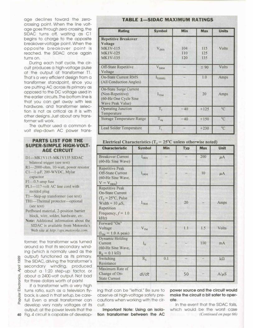
TABLE l-SIDAC MAXIMUM RATINGS
R.tIng Symbol Min Max Units
Repetitive Breakover Voltage MKIV-115 V (80) 104 115 Volts MKIV-125 110 125 MK IV-1 35 120 135
OlI-State Repetitive V ORM - ± 90 Volts Voltage On-State Current RMS IT( R/lI SJ - 1.0 Amps (All Conduction Angles)
On-State Surge Current (Non-Repetitive) ITSM - 20 Amps (60-Hz One Cycle Sine Wave Peak Value) Operaling Junction T, - 40 + 125 ·C Temperature Storage Temperature Range T .. - 40 + 150 ·C
Lead Solder Temperature T, - + 230 ·C
Electrical Characteristics (T, = 2S·C unless otherwise noted)
Characteristic Symbol Min
Breakover Current '(80) -(60-Hz Sine Wave)
Repetitive Peak OfT-State Current loM.'1 -(60-Hz Sine Wave. V = V DRM)
Repetitive Peak On-State Current (T c ~ 25·C. Pulse Width = 10 /LS , 1TR.. .. 1 -Repetition FrequencyJ = 1.0 kHz) Forward "On" Voltage V"., -(I", = 1.0 A peak) Dynamic Holding Current III -(60-Hz Sine Wave, R, = 0.1 kil)
Switching R, 0.1 Resistance Maximum Rate of Change of On- di/ dt State Current
ing that can be -lethal: Be sure to observe all high-voltage safety precautions when working with the circuit.
Important Note: USing an isolafton transformer between the AC
-
Typ Max UnH
- 200 /LA
- iO /LA
20 - Amps
1.1 1.5 Volts
- 100 rnA
- - kil
50 - N/LS
power source and the circuit wouid make the circuit a bit safer to operate.
In the event that the SIDAC falls. which would be the warst case
(CmulI1ued 011 page 66)
DTMF INTERFACE (continued /rom page 34)
0-9, " # several times, and then hong up the phone,
Once the answering machine resets, simply remove the tope and ploy It bock using a cossette recorder with on earphone jock. After cueing up the tope to the porflon containing the DTMF tones, connect the interface to the recorder's earphone jock, and ploy bock your test tope. DTMF digits should now begin appecring on your monitor, If no digits appear, try raising or lowering the tope recorder's (or scanner's) volume-control seffing and try again, However, normal volume should suffice.
If Incorrect digits appear on the monitor (for example, the digit received was known to be a DTMF "1: but a "4" was displayed), then re-check the wiring of the DB-25 connector and try again , After everything Is working properly, install the cover onto the enclosure, and show your friends that useful monitoring accessories don't have to be expensive, •
HIGH-VOLTAGE CIRCUIT (continued/rom page 40)
condition, RI would toke the full 117 -volt line, dissipating approximately 7.2 watts. At the maximum line-voltage tolerance of 117 volts AC + 10%, or about 129 volts AC, the resistor would have to dissipate about 8.3 wotts. If a 10- or 2O-watt resistor were used, you'll probably never have a problem. But if you are concerned, the optional thermal c ut-out protector mentioned earlier can be attached to Rl to
0\ provide added protection for the 8l_ circuit in the event of a catastroph-~ ic failure.
Ii Construction, The author's proto'E e type unit was assembled on a small g section of perforated construcflon W board measuring approximately 6 ~ by 2'1" Inches (which is about the ~ width the transformer's bose),
Assemble the circuit, using Fig, 4 (the circuit's schemaflc diagram)
66 as a guide. Stort by temporarily
mounting the components to the perfboard section, When mounting power resistor R 1, be sure that It is mounted away from anything flammable and that sufficient space Is provided between the power resistor and any other components to allow good air flow around the resistor. Note: Although the author specifies a 100watt power resistor In the Ports List, the unit used In the prototype is a 50-watt, metalenclosed unit. Using a resistor of sufficient power-handling capacity helps to guard against possible mishap.
T1
TH1 ' 2K ~A' e' l
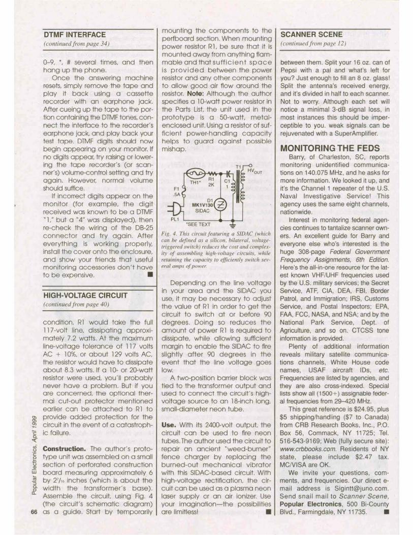
Fig. 4. This circuit featuring a SJDAC (which can be defined as a silicon. bilateral. vO/lagetriggered switch) reduces the cost and complexIty of assembling high-\'olwge circuilS. while rcramillg 'he clIpadty to ejJiciemly swirch several amps 0/ power
Depending on the line voltage In your area and the SIDAC you use, it may be necessary to adjust the value of Rl In order to get the circuit to switch at or before 90 degrees. Doing so reduces the amount of power Rl Is required to dissipate, while allowing sufficient margin to enable the SIDAC to fire slightly after 90 degrees In the event that the line voltage goes low,
A two-pOSition barrier block was tied to the transformer output and used to connect the circuit's hlghvoltage source to on 18-inch long, smail-diameter neon tube,
Use_ With Its 2400-volt output, the circuit can be used to fire neon tubes. The author used the circuit to repair on ancient "weed-burner' fence charger by replacing the burned-out mechanical vibrator with this SIDAC-based circuit, With high-voltage rec flfication, the c ircuit can be used as a plasma neon loser supply or on air ionizer, Use your Imagination-the possibilities are limitless I •
SCANNER SCENE (comil/ lled from page 12)
between Ihem. Split your t 6 oz. can of Pepsi wilh a pal and what's leh for you? Just enough to fill an 8 oz. glass! Split the antenna's received energy, and it's divided in half to each scanner. Not to worry. Although each set will notice a minimal 3-dB signal loss, in most instances this should be imperceptible to you. weak signals can be rejuvenated with a SuperAmplifier.
MONITORING THE FEDS Barry, of Charleston, SC, reports
monitoring unidentified communica· tions on 140.075 MHz, and he asks for more information, We looked it up, and it's the Channel 1 repeater of the U.S. Naval Investigative Service I This agency uses the same eight channels, nationwide.
Interest in monitoring federal agencies continues to tantalize scanner owners. An excellent guide for Barry and everyone else who's interested is the huge 30B-page Federal Government Frequency Assignments, 6th Edition. Here's the all-in-one resource for the latest known VHF/UHF frecuencies used by the U.S. military services; the Secret Service, ATF, CIA, DEA, FBI, Border Patrol, and Immigration; IRS, Customs Service, and Postal Inspectors; EPA, FAA, FCC, NASA, and NSA; and by the Nalional Park Service, Dept. of Agriculture, and so on. CTCSS tone information is provided.
Plenty of additional information reveals military satellite communications channels, White House code names, USAF aircrah IDs, etc, Frecuencies are listed by agencies, and they are also cross-indexed. Special lists show all (1500+) assignable federal frecuencies from 29-420 MHz.
This great reference is $24.95, plus $5 shipping/handling ($7 to Canada) from CRB Research Books, Inc., P.O, Box 56, CommaCk, NY 11725; Tel, 516-543-9169; Web (fully secure site): www.crbbooks.com. Residents of NY state, please include $2.4 7 tax. MCNISA are OK.
We invite your questions, comments, and frequencies. Our direct email address is [email protected], Send snail mail to Scanner Scene, Popular ElectroniCS, 500 Bi-County Blvd" Farmingdale, NY 11735, •