Embed Size (px)
Citation preview
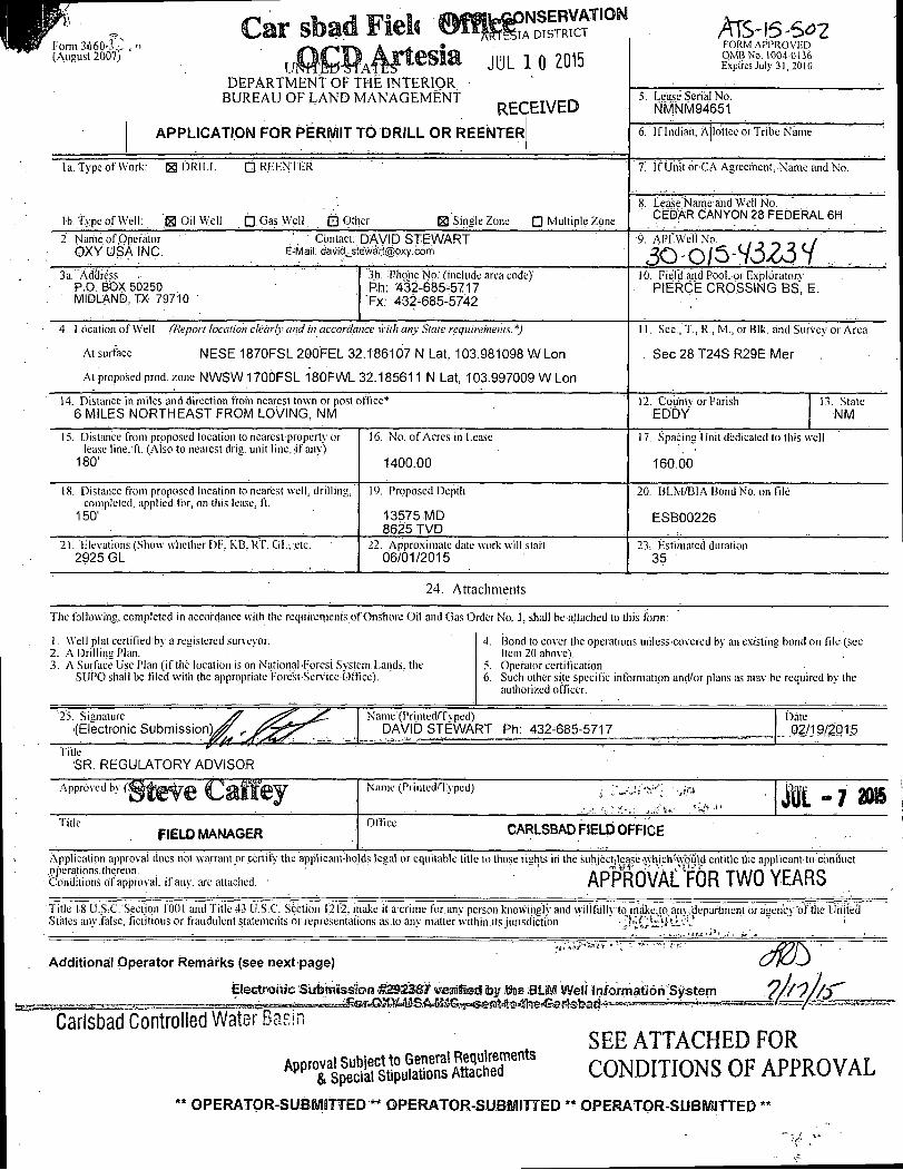
Form 3i604,;, (August 2007)
,Q0NSERVATIOINI ' fS lA DISTRICT
JUL 1 0 2015 DEPARTMENT OF THE INTERIOR
BUREAU OF LAND MANAGEMENT RECEIVED
APPLICATION FOR PERMIT TO DRILL OR REENTER
Af5-\SS07 FORM APPROVED OMB No. 1004-0136 Expires July 31,2010
5. Lease Serial No. NMNM94651
6. If Indian. Allottee or Tribe Name
la. Type of Work: H DRILL Q REENTER
lb. Type of Well: g j Oil Well Q Gas Well. • Other
7. If Unit or-CA Agreement. Name and No.
H Single Zone • Multiple Zone
8. Lease Name and Well No. CEDAR CANYON 28 FEDERAL 6H
2. Name of Operator OXY USA INC.
.'. C ontact: DAVID STEWART E-Mail: david^ste'wart@oxy:cdm
•9. API Well No. , , - _ . /
3 a.' Address P.O. BOX 50250 MIDLAND. TX 79710
3b. Phone No. (include area code)' Ph: 432-685-5717 Fx: 432-685-5742
10. Field .and Pool, or Exploratory PIERCE CROSSING BS, E.
4. Location of Well (Report location clearly.and in accordance with any State requirements, *)
At surface NESE 1870FSL 200FEL 32.186107 N Lat, 103.981098 W Lon
At proposed prod, zone NWSW 1700FSL 180FWL 32.185611 N Lat, 103.997009 W Lon
11. Sec, T., R., M., or Blk. and Survey or Area
Sec 28 T24S R29E Mer
14. Distance in miles and direction from nearest town or post office* 6 MILES NORTHEAST FROM LOVING, NM
12. Countv or Parish EDDY
13. State NM
15. Distance from proposed location to nearest property or lease line. ft. (Aiso to nearest drig. unit line, if anv)
180'
16. No. of Acres in Lease
1400.00
17. Spacing Unit dedicated to this well
160.00
18. Distance from proposed location to nearest well, drilling, completed, applied for, on this lease, ft.
150'
19. Proposed Depth
13575MD 8625 TVD
20. BLM/BIA Bond No. on file
ESB00226
21. Elevations (Show whether DP". KB. RT. Gl.-, etc. 2925 GL
22. Approximate date work will start 06/01/2015
23. Estimated duration 35
24. Attachments
The following, completed in accordance with the requirements of Onshore Oil and Gas Order No. 1, shall be attached to this form:
1. Well plat certified bv a .registered survevor. 2. A Drilling Plan. 3. A Surface Use Plan (if the location is on National Forest System.Lands, the
SUPO shall be filed with the appropriate Fore'st-Service Office).
4. Bond to cover the operations unless covered by an existing bond on file (see Item 20 above).
5. Operator certification 6. Such other site specific information and/or plans as may be required by the
authorized officer.
25. Signature
(Electronic Submission^^ rsrs&/^^ Name (Printed/Tvped)
DAVID STEWART Ph: 432-685-5717 Date
„ 02/19/2015
Title " SR. REGULATORY ADVISOR
Approved by ( j g f j g ^ g C a f f f e y Name (Printed/Typed) JUL -7 m Title
FIELD MANAGER Office
CARLSBAD FIELD OFFICE
Application approval docs not warrant or certify the applicanVholds legal or equitable title to those rights in the subjectjl^e^tlich^uia entitle the applicanfto conduct
• Conditions of approval, if any, are attached. APPROVAL FOR TWO YEARS Title 18 U-SsC.'Section 1.001 and Title 43 U.S.C. Section 1212, make it a crime for.any person 'knowingly and willfully to make.tO; any/department or agency"! States any.false, fictitious or fraudulent statements or representations as to any matter within.its jurisdiction. • • ' ^ C & ' f A i ^ V ~
'of the United
Additional Operator Remarks (see next page)
Carlsbad Controlled Water Baslr
Electronic Submission £2S23&f verified by Sue BLM Well Information System 2hh Approval Subject to General Requirements
& Special Stipulations Attached
SEE ATTACHED FOR CONDITIONS OF APPROVAL
OPERATOR-SUBMITTED '** OPERATOR-SUBMITTED ** OPERATOR-SUBMITTED **
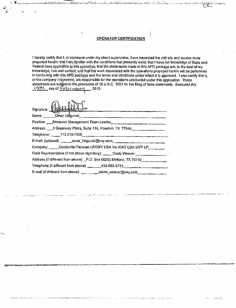
OPERATOR CERTIFICATION
I hereby certify that I, or someone under my direct supervision, have inspected the drill site and access route proposed herein; that I am familiar with the conditions that presently exist; that I have full knowledge of State and Federal laws applicable to this operation; that the statements made in this APD package are, to the best of my knowledge, true and correct; arid that (he work associated with the operations proposed herein will be performed in conformity with this APD package and the terms and conditions under which it is approved. I also certify that I, or the company I represent, am responsible for the operations conducted under this application. These statements are subject to the provisions of 18 U.S.C. 1001 for the filing of false statements. Executed this
Signature: | ^ f f i | 4 4 & ^ 4 ;
Name:. Omar Llslgurski_
Position: Reservoir Management Team Leader
Address: 5 Greenway Plaza, Suite 110, Houston. TX 77046.
Telephone: 713-215-7506.
E-mail: (optional): [email protected].
Company: Occidental Permian LP/OXY USA Inc /OXY USA WTP LP
Field Representative (if not above signatory): Dusty Weaver
Address (If different from above): _P.O. Box 50250 Midland, TX 79710.
Telephone (if different from above): _ 432-685-5723.
E-mail (if different from above); [email protected].
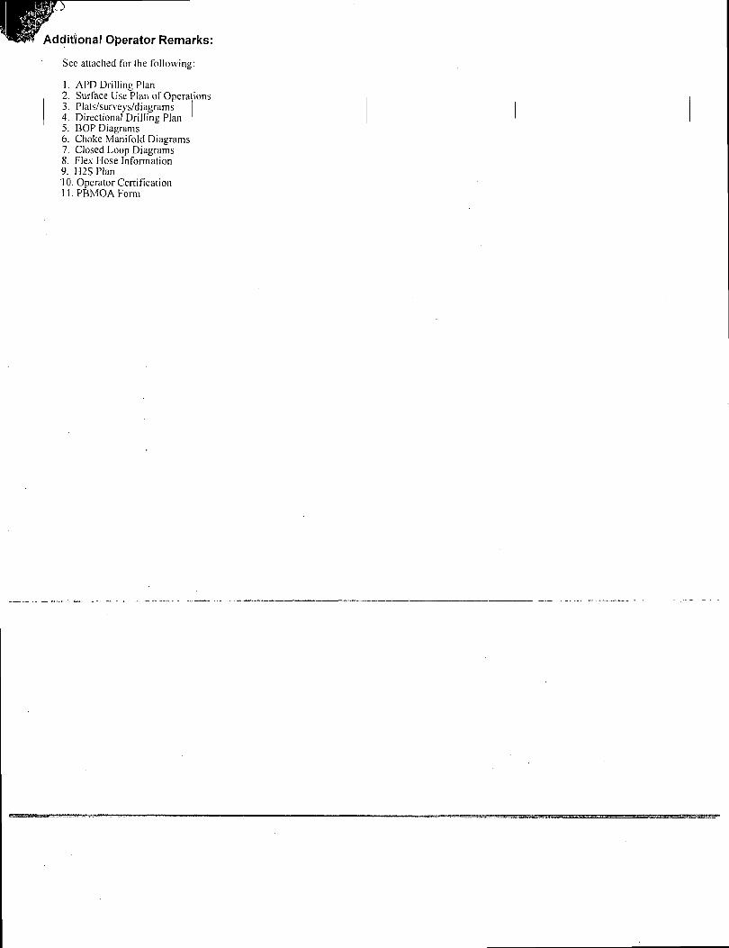
Additional Operator Remarks:
See attached for the following:
1. APD Drilling Plan 2. Surface Use Plan of Operations 3. Plats/surveys/diagrams I 4. Directional Drilling Plan 5. BOP Diagrams 6. Choke Manifold Diagrams 7. Closed Loop Diagrams 8. Flex Hose Information 9. H2SPlan 10. Operator Certification 11. PBMOA Form
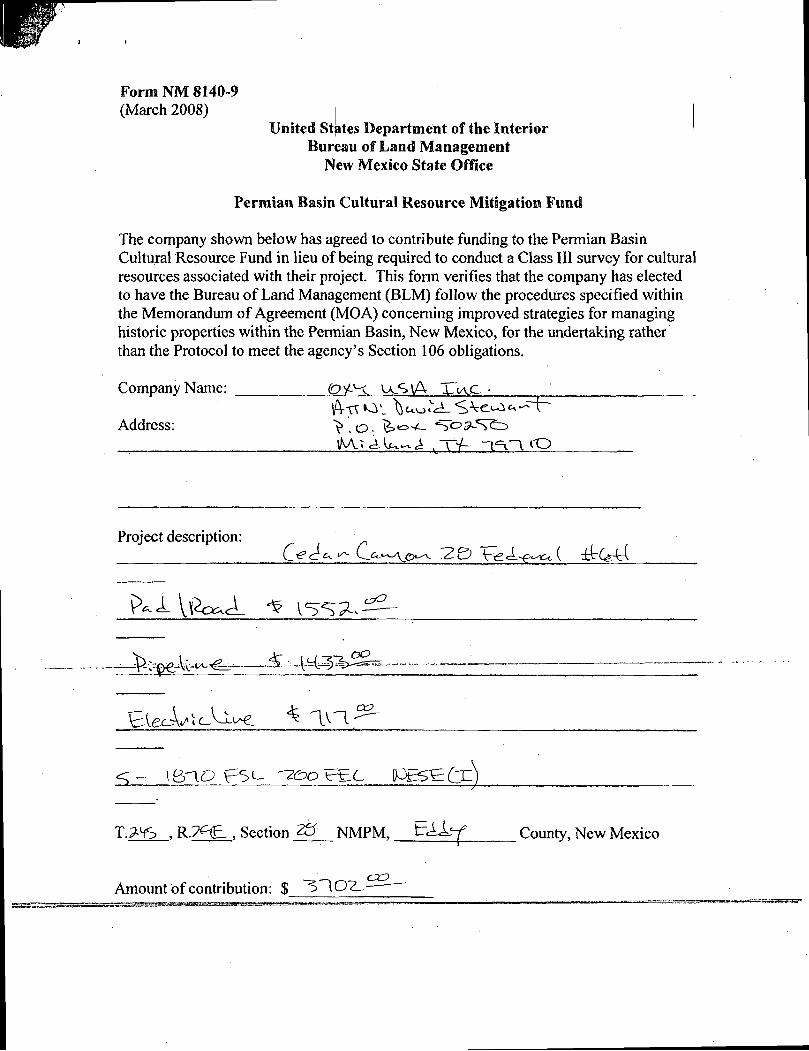
Form NM 8140-9 (March 2008)
United States Department of the Interior Bureau of Land Management
New Mexico State Office
Permian Basin Cultural Resource Mitigation Fund
The company shown below has agreed to contribute funding to the Permian Basin Cultural Resource Fund in lieu of being required to conduct a Class III survey for cultural resources associated with their project. This form verifies that the company has elected to have the Bureau of Land Management (BLM) follow the procedures specified within the Memorandum of Agreement (MOA) concerning improved strategies for managing historic properties within the Permian Basin, New Mexico, for the undertaking rather than the Protocol to meet the agency's Section 106 obligations.
Company Name: Oi^-X. <JLS\A X~IA,C •
Address: *>.o, >«=> - -S"OSL5V£=>
lM.x_tUt.~i ..TV- ~l"=v~V i Q
Project description:
^ g f e W f e ? - & -vM
C C
iBlO BL- iPES^BCX^
T._____, R __£__» Section 20 NMPM, t rAlz-f County, New Mexico
cxz> Amount of contribution: $ ~^T\01^- —
1S1SN. Ftaxtt fir, Habts, WflSM» HKK: {SIS) 393-6161 Fax: (S?J) M30TX
SUS.FkstSt, Aiosia, \W SS2>0 Pine? (S7S) 74i-imfei: (S7S) 743-9X0 Distrain' , I •1000Rio Br&vs R&4 AZx, KMSTilO Pitts: (SOS) 334417$ Tax: (SOS) 3M-61T0 District IV. 1220S.Stfcx^Dz,SatiFf,fa/SmS PiSd (SIS) 4TUiV)'tia: (SdSj47&34$2
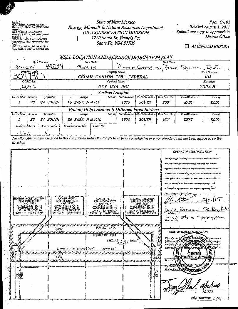
State of NewMexico Energy, Minerals & Natural Resources Department
OIL CONSERVATION DIVISION 1220 South St. Francis Dr. '
Santa Fe3 NM 87505
Form C-102 Revised August 1,2011
Sub.mii one copy to appropriate District Office
• AMENDED REPORT
WELL LOCATION AND ACREAGE DEDICATION PL AT API Numbs?
?o-cM<s ct3Z5Lj Poo} Code PooJ.Nmne
Pnopezty Nome '
CEDAR CANYON "28" FEDERAL 1 Well Number
6H OORIDNo. Operator Name
OXY USA INC. Elevation
2924.8' Surface Location
UL or lot so.
I Section
28 ,
TovmsBp
24 SOUTH
Rknge
29 EAST, N.M.P.M. LotIdn Feet from the
1870'
North/South line
SOUTH
Feet , from the
200'
EistfWestlms
EAST
County
EDDY
Bottom Hole Location If Different From Surface UL or lot ,no.
L
Section
28
Towvisiirp
24 SO UTH ;
Xsnge
29. EAST, N.M. P. M. ,
Lot Idn Feet from the
1700'
North/SouSiline
SOUTH • 180'
Eost'West line
fffiST
County
EDDY
Dedicated Acres Joint crlnffll j
A \ Consolidation Cods Order No.
No allowable will be assigned iotMs^mplction until all interests have been consoliiMedorsmm^tmdardmithasibem approved by tbe dhision.
iBOTTOM 'HOLE'mOWtONl
iNEw :weaco JEKST Tf =*3i1-4dS_33 US iT7 :X=EC«043.,1.-S IDS ;FT LAT.: N 32.1856 If! 4*
LGHG.: *03.9g7Q39«r
liBtl MEiSCO £ASi ' W«S 152?
!*<**m40s-.i2 lis IFW CAT.: ,M mm^tZ.
UPPER PERF. •NEW .WEXiCQ E*>ST
K m 1927 'C-43H33.84 iUS RT •K=60aS40.V8 US FT i L f t t : W 32.1BS6393-
S.QSG.: W •1Cl3i98.152!Q3-
.J3Q':| T PROJECT VtiSEA
WRODUGIMS ''/SEA
•530'f 11
£m.m"
•'3301
4-o t o
IT-;
f j .
OPERATOR CERTIF1CA TION
/ C K r ^ _ 5 c r . -ft? jfjffetaz&sT cxct&xsf '£av& is fits? e a /
.
^ ( ^ ( ( S -
' j f iKiBSMiOB " . " ~
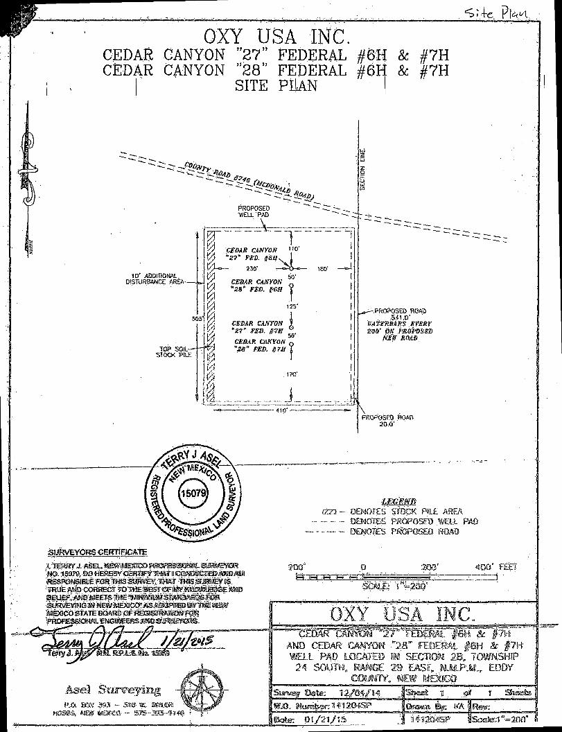
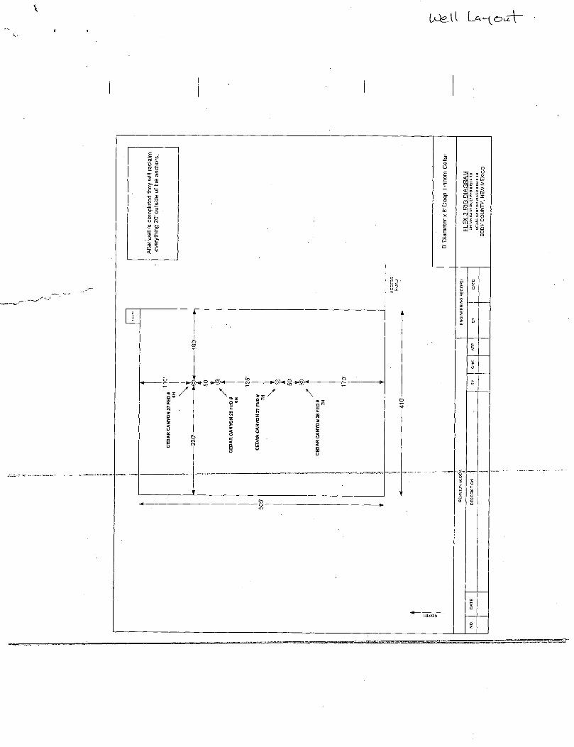
OXY USA INC. CfCDAS CANYON "27" FEDERAL #6H 8c #7H CEDAR CANYON 28 FEDERAL #6H
SITE PLAN & #7H
PROPOSED WELL "PAD
10" ADDIT10P4AL. DISTURBANCE AREA-
TOP. SOl-STOCK PiLE
rW~:. r" y &DAR CANYON " ° ' KA "2?" #6.ffN 1 V % o — 230' — » ^ o — » -
230'
CEBAR CANrON "28° FED. #'6»
50'
1 125'
CSBAR CANYON "27° FSB. &7U
CESAR CANYON "2ti" FSB. S7S
50'
1?fl'
1 4 ! 0 ' -
r-,PROP0fSEO ROAD .541.0'
r/AT£RSARS SfESi' 2as'oar pROP&sm
N£Sf ROA3
PROPOSED mm 20.0'
SURVEYORS CEffTCFiGATE
i, TERRY j. ftSEL, nmimmxtmmsdm^^m«^m 'mO. 15079, BO WEttBYCiEKWVTmm& mWSjtEO/A3«3«
;TOUE AMD CORRECT J O l l i B W W W S p S a j BEUEiR.jSNDlsJEETS ™ E « r « M j s i « S W 3 S O T
l J,& B3K 3S3 - S1!<f aRWJR!
Mesas* MES waesa •- sjs-asa-^**©
lEGEm
(ZZ2- OB'iOTES S'feCK RLE AREA
DENOTES PROPOSED .DELL PAD
DENOTES P/83POSEO RCWD
200" J 200' 400' F££7
7
AND CEDAR CAWON •",28"" FHSER L #SH & |7H' PAD LOCATE© m SECmn 28,* TOWNSHIP
24 SOOTH, RAftGE 29 EAST, U..MPM.r EDDY | COUMIY, NEW SEMICO j
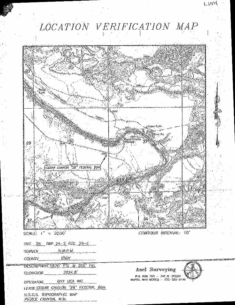
LUlM
W C AT tON VERIFICAT
*£\ f t \
3-
CEDAR C4N\0N "2S" FEDERAL
<c . t -
2000
Set.. -Mi.. gfe.-Mrrg. -Rgk
mm.
OT^SP?, . , , y
« a BfK 3S3 - 3*s. '*v. -amm
^ M E M S ^ B E m R ^ m m M ^ ^ ^ i F ^ m M ^ M M r - - ———— — —
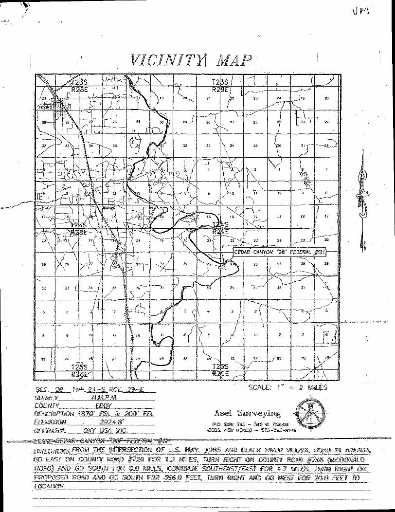
.CftBGWCTgy'*^ ,7HE p^g^CWBg. &F SULS. !r«y. .£'285 J^O BLACK 'RMUR miMSEJ&MB m mUM®* pB EAST :0M C Q i t j ^ f ¥ i » p f Z _ J FGW. iLJI Mi£S„ WR-K' SSHT fffli ;G6:LM3¥ SMflli <^dLMjM|S ' mm)' ..mm GO stmm ftm &M mss,, ciw^^o^^rm^i/Exsf'^cm 4.7 mms., '^Mm matr. <m. m&msEB mm » <QQ ssim ras? jas&a reo; mm mmr mm m mzsfr ''nrn'mm IREO" io tomtom.
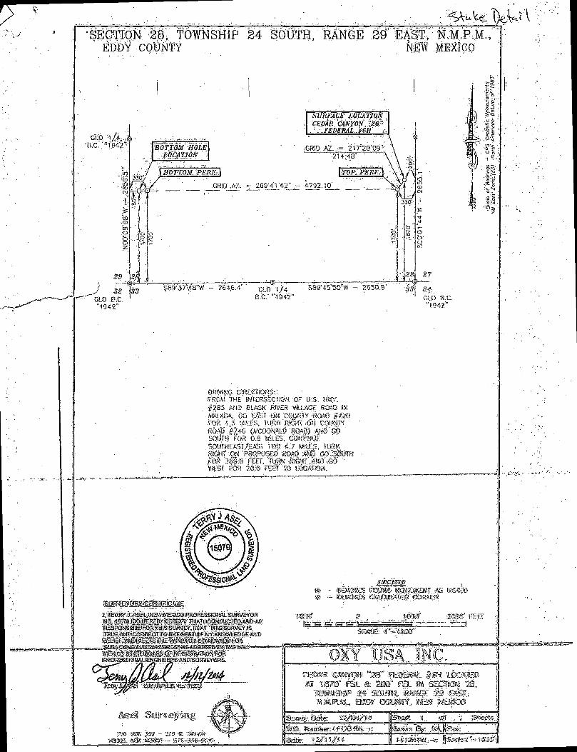
•SECTION 28, TOWNSHIP EDDY COUNTY
24 SOUTH, RANGE 29 EAST, N.M.P.M. MEW :M;E#GO
GtO "1/4, B.C. "1;K>"
SURFACE LOCATION CEDAR CANrOiV. $8%
. ' . FEDERAL J6H' i
iGRlD .A2....= 217;20'09"-?14.48' • ~ " \ ^
\mp:pBRFA
4792.10' . • '
330'
•32 \S3 U.O B.C "•1Q42"
S89'45"50"W - 2850.9' 'S3
27
•3.f GLO B.C. "!94?."
OHiySNG biROSTtoNS:.: f'RCM THE JMTEBSECTfON. 'OF KigY. #285 AMD BLACK fW£R ViiLSGE ROSO IN •'MALAGA, GO EAST .0K 'COUNT* 'ROAG #720. FOR -1.3 ffflllES, TURK RSgXf :Of3 COS>MTY
ROAO .#746'im6(h&6 -koAii)-.M6'-Gib SOUTH FOR 0.6 MSLES, SOUVHEAST/EAST FOR- 4.7 MifcES, TURK RiGHT %M -PROPOSE© WMSS MSS .GOMS&IH .FOR 366:0'FEEr, TURK RS^r AK©":GO '
v/ESf FOR 2®:<$ <em TO t«yw«o«.
i ^ u i e ^ ^ s ' i i ^ B ^ . l S t r ^ m S i w S ' j B
® - ps«sies iMSsis Ikwassaw -as rasas
feel Sate e aaag
,s».e. taw 3ss - »» «
wtoar a W Sntp j
'• STA1"!*''. •'•!'•' j
i • ©If 1M,1IC'.-. , . 1 i ces« w » p "S3" mmazMt. fani ue
! W T O * ;24' S31MS,. KSSGE :-29 ©
j naj&pjwu mm mmw.. i & wok
« '2@» i &K ; ! as |
' j jSti'eets j
V
Si 5 IE •
M
\ • ® < - £ - W § H
\
20
29
GLO "1942"
21 N89-48'15'E 5318.3' 21
'28 28/
5- Uo t o t*S
to™
8 3 ". ^ £ S u> « ui ui • *
1/4 CORNER W ~ GtD " I9« " B.C.
22
12
N825PW:E.
UNE TABLE
+ + + + + \ 0 O " 1 W> t^v « 3
01 oo i^j
LINE BEARING DISTANCE
LI S7616'39~E •782.6'
L2 S76'I6'39"E 2125.3'
tJ S00VI'40"W 435.5'
14 S89'59'07"E 240.2'
15 N89-58'43"E 240.2'
(.6 S89'59'06"E 240.0'
' L7 S88-48'41°E 240.3'
32+75.6 TEE LEFT TO CEDAR CANYON 27 FEDERAL /6H LAT.~ 52.186369-N LONG.= I03 98236f N
33+25.6 TEE LEFT TO CEDAR CANYON 28 FEDERAL f6H LAT.= 32.186232-N LONG.= 103.982362-N
34+50.5 TEE LEFT TO CEDAR CANYON 27 FEDERAL J7H LAT.= 32.185889- N " LONC.= 103.982363-N
34+95,5 P,f, BS-SQW U. LAT.= 32.185765-N LONG* 103.982364-N
37+35.8 END SURVEY AT CEDAR CANYON 28 FEDERAL f7H
N06-4218 W 1706.2' (TIE)
28 USA 28 -<$>-
SPK. NAIL IN ROAD
22
27
33 GLO '1942'
S89'3I'26W 2647.1
B.C.
1/4 CORNER ao "1916" B.C.
SB9-45'44"W 2651.6' 33
-1942" B.C.
DESCRIPTION
SURVEY FOR A STRIF> OF LAND 50.0 FEET WIOE AND 4304.1 FEET OR 0.815 MILES IN LENGTH CROSSING USA LAND IN SECTION 28. TOWNSHIP 24 SOUTH, RANGE 29 EAST, N.M.P.M., EDDY COUNTY, NEW MEXICO, AND BEING 25.0 FEET LEFT AND 25.0 FEET RIGHT OF THE ABOVE PLATTED CENTERLINE SURVEY.
GREEN- SURFACE 782.6 FEET RED- BURIED 35215 FEET TOTAL- 4304.1 FEET
NOTE
1) BEARINGS SHOWN HEREON ARE MERCATOR GRID AND CONFORM TO THE NEW'MEXICO COORDINATE SYSTEM "NEW MEXICO EAST ZONE-NORTH AMERICAN DATUM 1983. DISTANCES ARE SURFACE VALUES.
2) LATITUDE AND LONGITUDE VALUES SHOWN HEREON ARE RELATIVE TO THE NORTH AMERICAN DA WM 1983 (NAD83).
I, RONALD J. EIDSON. NEW DO HEREBY CERTIFY THAU ON THE. GROUND UPON .SMI UNDER MY DIRECT SUP£RVISfi$bjHA-T~FAM. RESPONSIBLE FOR THIS SURVEY; THAT'THIS Sam* MEflS. THE MINIMUM STANDARDS FOR SURVEYING IN NEW Mtylwi, AN6 THXT2IT}IS TRUE''AND CORRECT TO THE BEST OF MY KNO^LWGE ANDREUE'
RONALD J. EIDSON
LEGEND
® DENOTES FOUND CORNER AS NOTED
WOO 1000 2000 FEET k d H . b l - S :
Scale: 1"=1000'
DATE:
T
PROVIDING SURVEYING SBRVICtS ' SINCE 1946
JOHN WEST SURVEYING COMPANY 412 N. DAL PASO HOBBS. NM. 88240
(S7S) 393-3117 wwK.jwx.biz TBPLS* 10021000
SURVEY FOR AN ELECTRIC LINE TO THE CEDAR CANYON27 FED. #6H, #7H
& FED. 28 MIL #7H CROSSING SECTION 28, TOWNSHIP 24 SOUTH, RANGE 29 EAST, N.M.P.M.
EDDY COUNTY, NEW MEXICO
Survey Dale: 2/13/15 CAD Dote: 2 /16/15 Drown By: LSL
© DRtfTING\lorenzo\2015\0XY US A. IMCVlEC IRK11WC 10 THE CEDAR CANYON ?7 FIE
^ W . O . No.: 15130525 | Rev: . 4 /23 /15 | Rel. W.O.: 15110235 [ Sheet 1 o(
ttO '1942" B.C.
20 I 21 N89'48'15"E 5318.3'
SPK. NAIL IN ROAD
21 I 22
29 28 28 27
ITS £ 8
.1/4 CORNER (•> ao "1942" B.C.
10+75.8 10+17.4
2+4UL 1+83 1+24.2
NIT4B28E
P.I. 85-54'50" Rl 5 8 4
~P.I. 20-38'26" RT. N02'49'58"W
499.3'
O+OO
LEASE RD. PA MV'52" LI BEGIN SURVEY AT THE CEDAR CANYON 28 CTB. FENCE
N88V7'37"E 124.2'
NI5SO'29"W ' 1937.3' (TIE)
N89'5I'34"E\ \ 20.3'
NI412'50'W '1748.1 (IK)
29 28 — .—.— 32 13 S89'3I'26"W 2647.1'
ao "1942" B.C.
USA 28 \ 27
1/4 CORNER GLO "1516" B.C.
S89'45'44"W 2651.6' t; 33 I 34 GLO. "1942" B.C.
DESCRIPTION
SURVEY FOR A STRIP OF LAND 50.0 FEET WIDE AND 4086.5 FEET OR 0.774 MILES IN LENGTH CROSSING USA LAND IN SECTION 28, TOWNSHIP 24 SOUTH. RANGE 29 EAST, N.M.P.M., EDDY COUNTY, NEW MEXICO, AND BEING 25.0 FEET LEFT AND 25.0 FEET RIGHT OF THE ABOVE PLATTED CENTERLINE SURVEY.
GREEN - SURFACE 1459.9 FEET SURF- BATT- TO FEE. RED - BURIED 2626.6 FEET BURIED OUT OF FEE LAND TOTAL - 4086.5 FEET
NOTE BEARINGS SHOWN HEREON ARE MERCATOR GRID AND CONFORM TO THE NEW MEXICO COORDINATE SYSTEM "NEW MEXICO EAST ZONE-NORTH AMERICAN DATUM 1983. DISTANCES ARE SURFACE VALUES.
LEGEND
® DENOTES FOUND CORNER AS NOTED
1000
fee 1000 2000 FEET
F=n=C 33= Scale:l"=IOOO'
/. RONALD J- EIDSON, NEW MEXICO SRdTgSJipNAVjSURVEYOR No. 3239. DO HEREBY CERTIFY THAT THIS SVR~ffiyX&AN&/mE>hACTUAL SURVEY ON THE GROUND UPON WHICH if lS^ASm V@Rf'PERIiORMED BY ME OR UNDER MY DIRECT SUPERVISION mAT&M?RE$Pm'SIBLfirOR THIS SURVEY; THAT THIS SURVEY tfEBlS THlZ/MiNIMUM.'SfyNDARDS FOR / — SURVEYING IN NEW MEXICO; ApiBTTIAT \T 1#SRU$ AND CORRECT TO j C~>">CT^V' f J A JTTsJY"^ ' THE BEST OF MY KNOWLEDGE | r | | ' f i L l C E ^ ^ / ; c r / V ^ ^ . * ~ * . * - J ' * - a M ^ ^ — ' "
RONALD J. EIDSON_ . _,
DATE: _. M/^/sMW^okP"
T
PROVIDING SURVEYING SERVICES SINCE 19-JS
JOHN WEST SURVEYING COMPANY 4U N. DAL PASO HOBBS, NM. B8240
(S7S) 393-3117 www.Jwsc.biz TBPLSt 10021000
SUR VEY FOR A PIPELINE TO THE CEDAR CANYON 27 FED. #6H, #711
& FED. 28 MM, #7H CROSSING SECTION 28, TOWNSHIP 24 SOUTH, RANGE 29 EAST, N.M.P.M.
EDO Y COUNTY, NEW MEXICO
Survey Dote: 2/13/15 CAD Dole: 4/23/15 Drown By. LSL
J^N.O. No.: 15130526 | Rev: . Rel. W.O.: 15110234 ©0R*rTING\Loicn2o\2015\OXr USA INC\P1PEUNE\R[- SOUIE CEDAR CANYON MLS IN SEC. 28 24S-29E
Sheet 1 of 1
A i 2974QI
f ^t^BSt5TBW SB559 2HESP !88S1 29171 29194 ll
~ J X 27977* 27PM 70.110 X
371
34874 3051K'
k ^ 304991 35039^12 X
2B373< X
J 41i184 348W
x
2S13J
27082'
2811B1
35041
25705 ' a \
J
UK
20
25
52 1 J
• ^ 'f^S- 1
? r-:.- n-... in mi \ \
^1, ..,„.-••> «•
27923!" i
-
27381' ' 273BtJf73Br f
3> © S tSfui |f f
— *=—^_l__h
X
200'
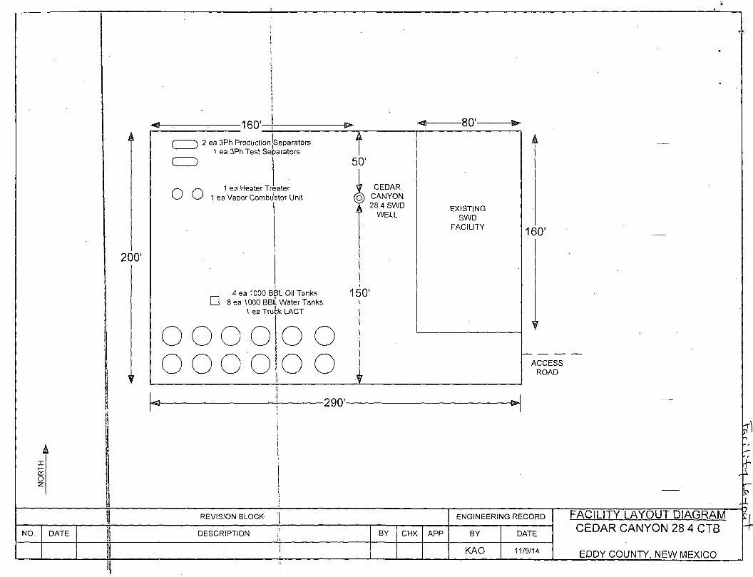
-160' i ( ) 2 ea 3Ph Production Jseparators
1 ea 3Ph Test Separators
O - ^ 1 ea Heater Treater w 1 ea Vapor Combu'stor Unit
-80'-
CEDAR CANYON 28 4 SWD
WELL
4 ea 1000 BBL Oil Tanks • 8 ea 1000 BBlL Water Tanks
1 ea Truck LACT
150'
O O O O o o o o
o o o o
EXISTING SWD
FACILITY
A
160'
ACCESS ROAD
-290'-
REVISION BLOCK- j ENGINEERING RECORD FACILITY LAYOUT DIAGRAM CEDAR CANYON 28 4 CTB NO. DATE | DESCRIPTION '•• BY CHK APP BY DATE
FACILITY LAYOUT DIAGRAM CEDAR CANYON 28 4 CTB
KAO 11/9/14 EDDY COUNTY, NEW MEXICO
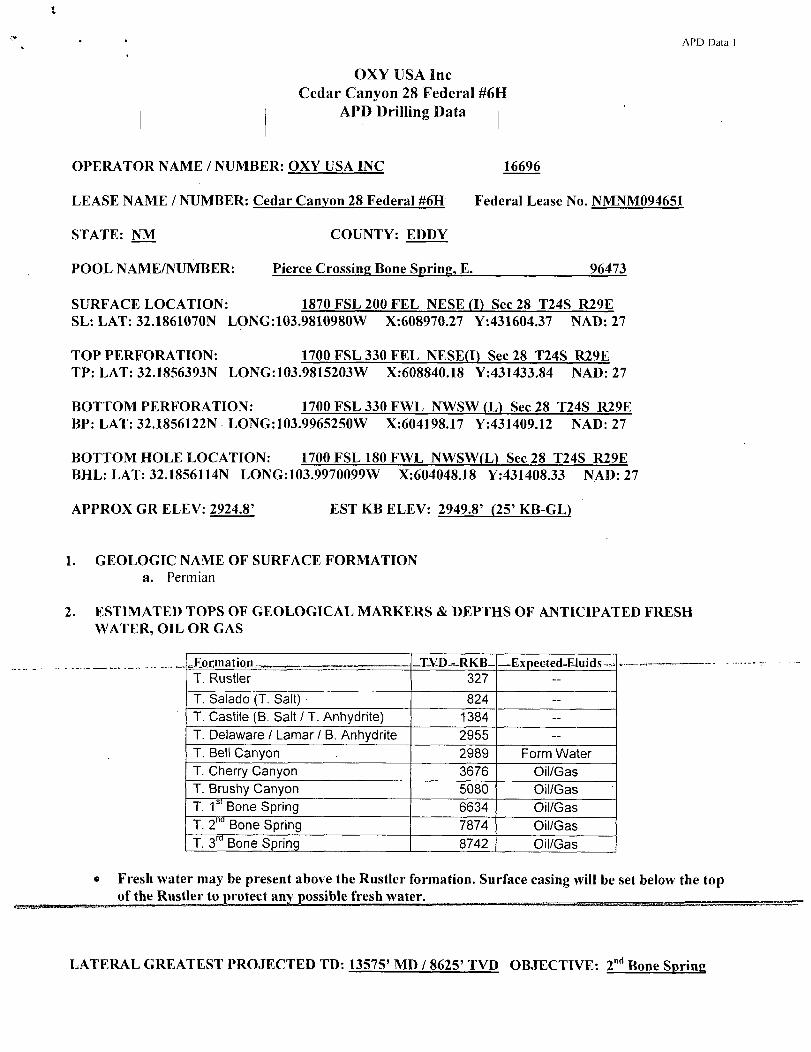
APD Data 1
OXY USA Inc Cedar Canyon 28 Federal #6H
APD Drilling Data i
OPERATOR NAME / NUMBER: OXY USA INC 16696
LEASE NAME / NUMBER: Cedar Canyon 28 Federal #6H Federal Lease No. NMNM094651
STATE: NM COUNTY: EDDY
POOL NAME/NUMBER: Pierce Crossing Bone Spring, E. 96473
SURFACE LOCATION: 1870 FSL 200 FEL NESE (I) Sec 28 T24S R29E SL: LAT: 32.1861070N LONG-.103.9810980W X-.608970.27 Y-.431604.37 NAD: 27
TOP PERFORATION: 1700 FSL 330 FEL NESE(D Sec 28 T24S R29E TP: LAT: 32.1856393N LONG:103.9815203W X:608840.18 Y:431433.84 NAD: 27
BOTTOM PERFORATION: 1700 FSL 330 FWL NWSW (L) Sec 28 T24S R29E BP: LAT: 32.1856122N LONG:103.9965250W X:604198.17 Y:431409.12 NAD: 27
BOTTOM HOLE LOCATION: 1700 FSL 180 FWL NWSW(L) Sec 28 T24S R29E BHL: LAT: 32.1856114N LONG:103.9970099W X:604048.18 Y:431408.33 NAD: 27
APPROX GR ELEV: 2924.8' EST KB ELEV: 2949.8' (25' KB-GL)
1. GEOLOGIC NAME OF SURFACE FORMATION a. Permian
2. ESTIMATED TOPS OF GEOLOGICAL MARKERS & DEPTHS OF ANTICIPATED FRESH WATER, OIL OR GAS
.Formation _T-VD--RKB- —E xpected-Eluids T. Rustler 327 -
T. Salado (T. Salt) 824 -T. Castile (B. Salt / T. Anhydrite) 1384 --T. Delaware / Lamar / B. Anhydrite 2955 -T. Bell Canyon 2989 Form Water T. Cherry Canyon 3676 Oil/Gas T. Brushy Canyon 5080 Oil/Gas T. 1 S I Bone Spring 6634 Oil/Gas T. 2 n a Bone Spring 7874 Oil/Gas T. 3 r a Bone Spring 8742 Oil/Gas
• Fresh water may be present above the Rustler formation. Surface casing will be set below the top of the Rustler to protect any possible fresh water.
LATERAL GREATEST PROJECTED TD: 13575' MD / 8625' TVD OBJECTIVE: 2 n d Bone Spring
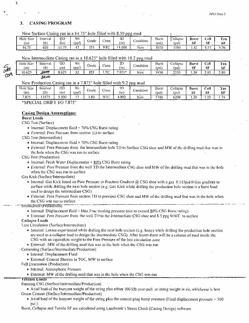
APD Data 2
3. CASING PROGRAM
New Surface Casing ran in a 14.75" hole filled wit i 8.50 ppg mud | Hole Size
(in) Interval
(ft) <f)D (in)
Wt (ppf)
Grade Conn ID
. (in) ' Condition
Burst (psi).
J ollapse (psi)
Burst SF
Coll SF
Ten SF
14.75 400 11.75 47 J55 BTC 11.000 New 3070 1510 1.42 8.57 5.76
New Intermediate Casing ran in a 10.625" iole filled with 10.2 ppg mud Hole Size
(in) Interval
(ft) OD (in)
Wt (PPf)
Grade Conn ID (in)
Condition Burst (psi)
Collapse (psi)
Burst SF
Coll SF
Ten SF
10.625 8.625 32 J55 LTC 7.921* New 3930 2530 1.30 2.93 2.80
New Production Casing ran in a 7.875" ho e filled with 9.2 jpg mud Hole Size
(in) Interval
(ft) OD (in)
Wt
(PPO Grade Conn
ID (in)
Condition Burst (psi)
Collapse (psi)
Burst SF
Coll SF
Ten SF
7.875 13575 5.500 17 L80 BTC 4.892 New 7740 6290 1.20 1.55 1.74
*SPECIAL DRIFT TO 7.875"
Casing Design Assumptions: Burst Loads CSG Test (Surface)
o Internal: Displacement fluid + 70% CSG Burst rating • External: Pore Pressure from section TD to surface
CSG Test (Intermediate) • Internal: Displacement fluid + 70% CSG Burst rating • External: Pore Pressure from the Intermediate hole TD to Surface CSG shoe and MW of the drilling mud that was in
the hole when the CSG was run to surface CSG Test (Production)
o Internal: Fresh Water Displacement +.80% CSG Burst rating • External: Pore:Pressure from the well TD the Intermediate CSG shoe and MW of the drilling mud that was in the hole
when the CSG was run to surface Gas Kick (Surface/Intermediate)
o Internal: Gas Kick based on Pore Pressure or Fracture Gradient @ CSG shoe with a gas 0.115psi/ft Gas gradient to surface while drilling the next hole section (e.g. Gas Kick while drilling the production hole section is a burst load used to design the intermediate CSG)
o External: Pore Pressure from section TD to previous CSG shoe and MW of the drilling mud that was jn the hole when the CSG was run to surface
^^StimulSioTi^Pr^KtiSn)" i. .. ' ' ~ o Internal: Displacement fluid + Max Frac treating pressure (not to exceed 80% CSG Burst rating) o External: Pore Pressure from the well TD to the Intermediate CSG shoe and 8.5 ppg MWE to surface
Collapse Loads Lost Circulation (Surface/Intermediate)
• Internal: Losses experienced while drilling the next hole section (e.g. losses while drilling the production hole section are used as a collapse load to design the intermediate CSG). After losses there will be a column of mud inside the CSG with an equivalent weight to the Pore Pressure of the lost circulation zone
o External: MW of the drilling mud that was in the hole when the CSG was run Cementing (Surface/Intermediate/Production)
o Internal: Displacement Fluid « External: Cement Slurries to TOC, MW to surface
Full Evacuation (Production) o Internal: Atmospheric Pressure o External: MW of the drilling mud that was in the hole when the CSG was run
TensionLoacls Running CSG (Surface/Intermediate/Production)
o Axial load of the buoyant weight of the string plus either 100 klb over-pull or string weight in air, whichever is less Green Cement (Surface/Intermediate/Production)
o Axial load of the buoyant weight of the string plus the cement plug bump pressure (Final displacement pressure + 500 psi)
Burst, Collapse and Tensile SF are calculated using Landmark's Stress Check (Casing Design) software.
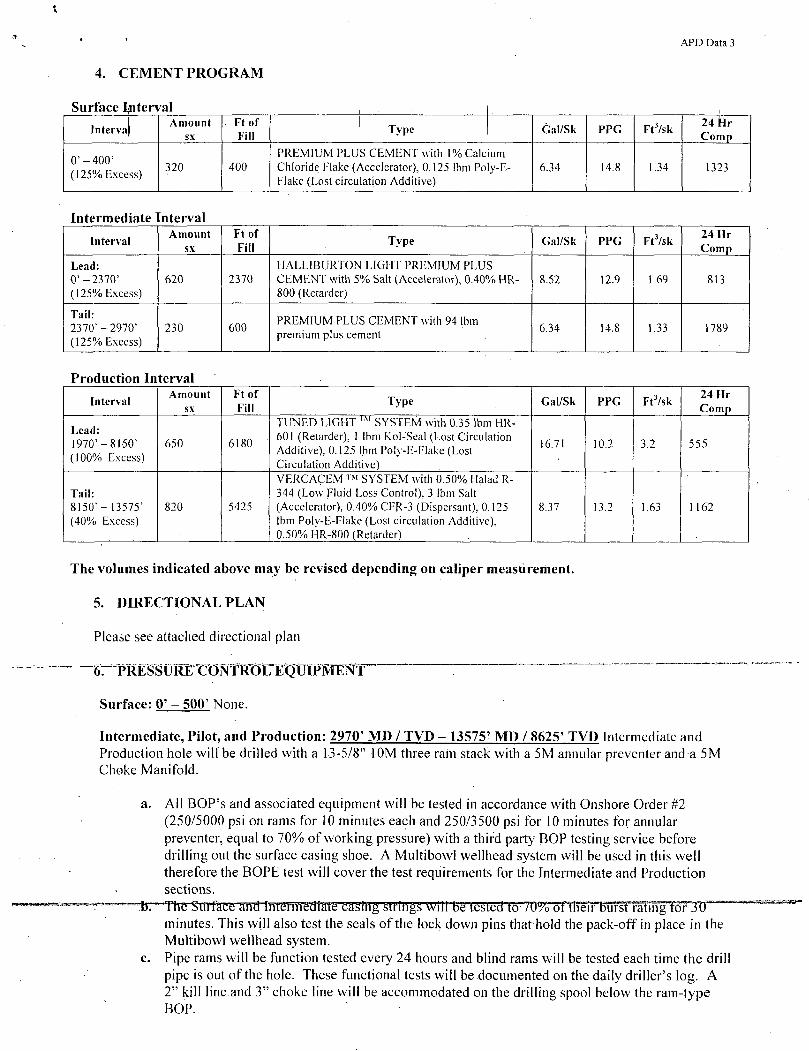
APD Data 3
4. CEMENT PROGRAM
Surface Interval Intervai
Amount sx
Ft of Fill ' Type Gal/Sk PPG Ft3/sk 24 Hr
Comp
0'-400' (125% Excess)
320 400 PREMIUM PLUS CEMENT with 1% Calcium Chloride Flake (Accelerator), 0.125 lbm Poly-E-Flake (Lost circulation Additive)
6.34 14.8 1.34 1323
Intermediate Interval
Interval Amount
sx Ft of Fill Type Gal/Sk PPG Ft3/sk 24 Hr
Comp
Lead: 0'-2370' (125% Excess)
620 2370 HALLIBURTON LIGHT PREMIUM PLUS CEMENT with 5% Salt (Accelerator), 0.40% HR-800 (Retarder)
8.52 12.9 1.69 813
Tail: 2370'-2970' (125% Excess)
230 600 PREMIUM PLUS CEMENT with 94 lbm premium plus cement
6.34 14.8 1.33 1789
Production Interval
Interval Amount
sx Ft of Fill
Type Gal/Sk PPG Ft3/sk 24 Hr Comp
Lead: 1970' - 81-50' (100% Excess)
650 6180
TUNED LIGHT I M SYSTEM with 0.35 lbm HR-601 (Retarder), 1 lbm Kol-Seal (Lost Circulation Additive), 0.125 lbm Poly-E-Flake (Lost Circulation Additive)
16.71 10.2 3.2 555
Tail: 8150' - 13575' (40% Excess)
820 5425
VERCACEM ™ SYSTEM with 0.50% Halad R-344 (Low Fluid Loss Control), 3 lbm Salt (Accelerator), 0.40%CFR-3 (Dispersant), 0.125 lbm Poly-E-Flake (Lost circulation Additive), 0.50% HR-800 (Retarder)
8.37 13.2 1.63 1 162
The volumes indicated above may be revised depending on caliper measurement.
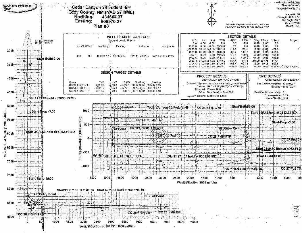
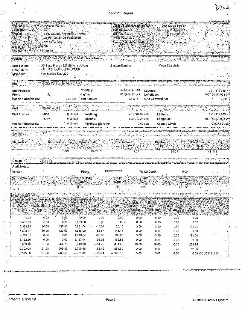
5. DIRECTIONAL PLAN
Please see attached directional plan
erPRESSURTCON^^ ~
Surface: 0' - 500' None.
Intermediate, Pilot, and Production: 2970' MD / TVD - 13575' MD / 8625' TVD Intermediate and Production hole will be drilled with a 13-5/8" 10M three rain stack with a 5M annular preventer and a 5M Choke Manifold.
a. All BOP's and associated equipment will be tested in accordance with Onshore Order #2 (250/5000 psi on rams for 10 minutes each and 250/3500 psi for 10 minutes for annular preventer, equal to 70% of working pressure) with a third party BOP testing service before drilling out the surface casing shoe. A Multibowl wellhead system will be used in this well therefore the BOPE test will cover the test requirements for the Intermediate and Production sections.
tr^he-SirffaCe antfltffern1Batate-caglHg Strings Will betested to 7d%-^mTT>uErfaAmffcWyU^ minutes. This will also test the seals of the lock down pins that hold the pack-off in place in the Multibowl wellhead system,
c. Pipe rams will be function tested every 24 hours and blind rams will be tested each time the drill pipe is out of the hole. These functional tests will be documented on the daily driller's log. A 2" kill line and 3" choke line will be accommodated on the drilling spool below the ram-type BOP.
APD Data 4
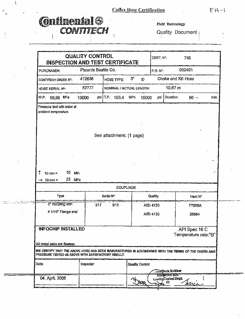
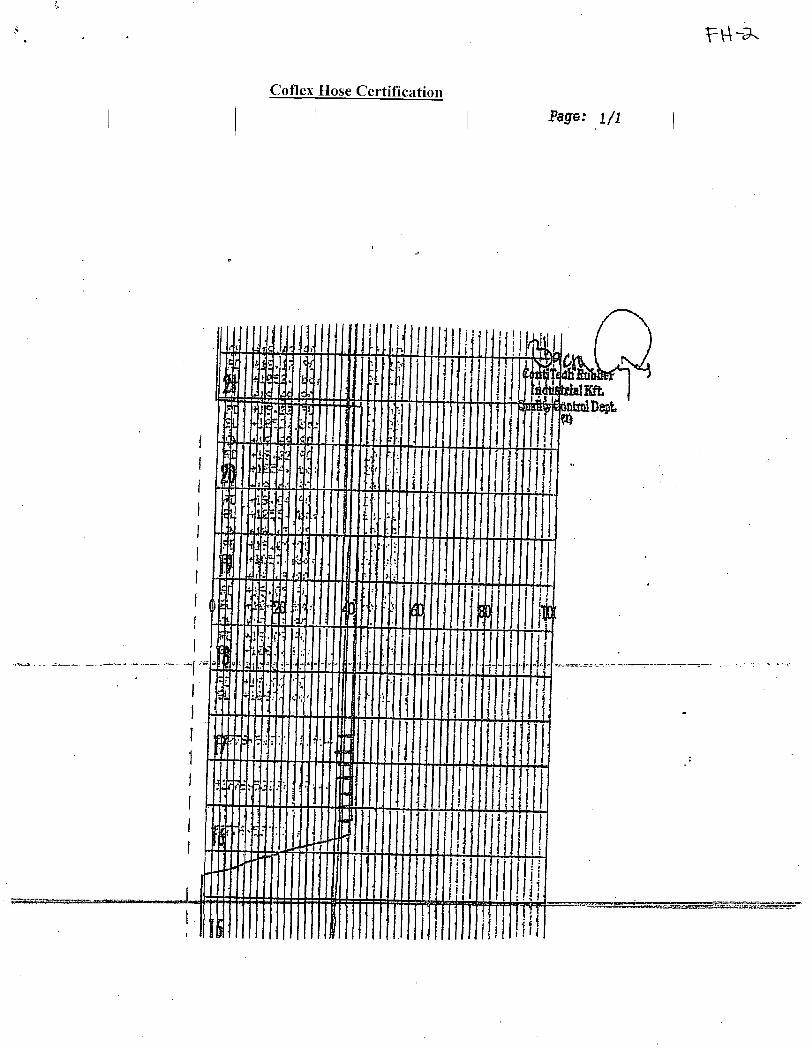
The BOPE test will be repeated within 21 days of the original test, on the first trip, if drilling the intermediate or production section takes more time than planned. Other accessory BOF equipment will include a floor safety valve, choke lines, and choke manifold having a 5Q00 psi working pressure rating and tested to 5000 psi. I The Operator also requests a variance to connect the BOP choke outlet to the choke manifold using a co-flex hose manufactured by Contitech Rubber Industrial KFT. It is a 3" ID x 35' flexible hose with a 10,000 psi working pressure. It has been tested to 15,000 psi and is built to API Spec 16C. Once the flex line is installed it will be tied down with safety clamps (certifications attached). BOP & Choke manifold diagrams attached.
7. MUD PROGRAM:
Depth Mud Wt
PPS Vis Sec
Fluid Loss
Type System
0'-400' 8.4-8.8 28-38 NC Fresh Water / Spud Mud 400' 10.0-10.2 28-32 NC Fresh Water / NaCl Brine
.^2970^- 13575' 8.8-9.2 28-34 NC Cut Brine / Sweeps
Remarks: Pump high viscosity sweeps as needed for hole cleaning. The mud system will be monitored visually/manually as well as with an electronic PVT. The necessary mud products for additional weight and fluid loss control will be on location at all times. Appropriately weighted mud will be used to isolate potential gas, oil, and water zones until such time as casing can be cemented into place for zonal isolation.
8. CLOSED LOOP SYSTEM
A closed loop system will be utilized, consisting of above ground steel tanks and haul-off bins. Liquids, drilling fluids and cuttings will be disposed of at an approved facility.
9. AUXILIARY WELL CONTROL AND MONITORING EQUIPMENT
a. A full opening drill pipe stabbing valve having the appropriate connections will be on the rig _ T.flpj3r.unpjb.s1r.uc,te.d and..readily.,accessible..atall.times _
b. Hydrogen Sulfide detection equipment will be in operation after drilling out the surface casing shoe until the production casing is cemented. Breathing equipment will be on location upon drilling the surface casing shoe until total depth is reached. If Hydrogen Sulfide is encountered , measured amounts and formations will be reported to the BLM.
10. POTENTIAL HAZARDS:
a. H2S detection equipment will be in operation after drilling out the surface casing shoe until the production casing has been cemented. Breathing equipment will be on location from drilling out the surface shoe until production casing is cemented. If H2S is encountered the operator will comply with Onshore Order #6.
b. No abnormal temperatures or pressures are anticipated. The highest anticipated pressure ._,it. ^ _Jr_ gradient is 0.48 psi/ft. Maximum anticipated bottom hole pressure is between 4140-psi.- ——.
c. All personnel will be familiar with all aspects of safe operation of equipment being used to drill this well. Adequate flare lines will be installed off the mud/gas separator where gas may be flared safely.
APD Data 5
11. ANTICIPATED STARTING DATE AND DURATION OF OPERATIONS
Road and location construction will begin after the BLM has approved the APD. Anticipated spud date will be as soon as possible after BL|VI approval and as soon as a rig will be|available. Move in operations and drilling is expected to take 35 days. If production casing is run, then an additional 30 days will be needed to complete the well and construct surface facilities and/or lay flow lines in order to place well on production.
12. WIRELINE LOGGING / MUD LOGGING / LWD
a. Mud loggers to be rigged up from intermediate shoe to TD. b. Acquire GR while drilling, from KOP to TD.
COMPANY PERSONNEL:
Name Linsay Earle Sebastian Millan Roger Allen Oscar Quintero
Title Office Phone (713)350-4921 (713)350-4950 (713)215-7617 (713)985-6343
Mobile Phone Drilling Engineer Drilling Engineer Supervisor Drilling Superintendent Drilling Manager
(832) 596-5507 (832) 528-3268 (281) 682-3919 (713) 689-4946
GbQnty, NM (Nfa© W NWiE) Worthing: 43160^37
&08§70.27
i V' \ KB @2949.8uift / r M ' Gr@1 292'4:8
3060-
a-556-
4000-
4500-
sooo-
'5500-
—-25--
16500-
7000-
?SD0-
B00D-
6500-
9000-
-U_4-
fSt^rt Build 3:00
H66 rStarf795144 hold at 3833.33 MD
Plan #3
c
+N/-S +E/-W ' Northing
0.0 0.0 431604.37
ELL DETAILS CC 28 Fed 6H 5round Level: 2924.8
Easting Latitude Longitude
608970.27 32°. 11' 9.985' N 103° 58'51.953 W
DESIG
Name TVD . .CC 28 F 6H BHL 8625:0-
GC 28 F 6"H LTP • 8628.0 GC 28 F 6H FTP 8710:0
1 . \ . . . . . . "... N TARGET DETAILS
1-N/-S +E/-W Northing' Easting |i 96:0 -4922.1 43140S'.33 604048.18 p95.3 -4772.1 431409 1? 604'98. "7 j!70.5 -130.1 431.433\84 608840.18
To convert Magrietic.North'td'Grid.Add 7.18° To convert Trae'North fo Grid^Subtract O.'f 9'
Azimuths'tpGrid; Ndi •" t rue'?iqf th: - 0 : i
Magnetic'Nofth: 7.1
Magnetic' ftt • Strength:-4834'.1.3si
Dip Angle: "60.0 Date: .1^/20^ ••Model:. HD6
SECTION DETAILS MD 0.0
3500r0 3833^3 4628:8' 4962':1 81152.6 9063:4-9304.0
13575.4
Inc 0.00 0.00
10.00 1.0.00 o:oo 0.00
91.08 91.08 91.08
Azi 0.00 0.00 •
120.00 120.00' ' 0.00-
0.00 264.75 269.56 269.56
TVD 0.6
3500.0: 3 S31.6 4615.0 4946 6 8-137.. 1 8710.0 8705.5 8625.0
+.N/-S 0:0
. oto • 14.5 -83:6 -98.1 -98.1
-151.5 -163 4 -19*6:0
•0.0 Of'O
25,1 ' 14'4~'.7 1G9'9
.169.9". -4:11.4 -651.C
4922.,1
DtegfTFace 0.00. .0:00 o:bo JCLQO— 3:00 120:00' o-oo o.co • 3 00180:00.
-0.00-' 0.00. .10.00.264.75;
2:00 89.96" *0:'00'- OiOO
VSect Target. 0.0: 0 0
-24.5 -141.3 -165:8 -1658 417.1 657.6
4926>CC 28 F 6H.BHL
-Start Drop -3.00 1000-[ J t 1_
PROJECT DETAILS: Eddy County. NM (NAD'27-NME)
Geodetic System: US State piane-i927:(Exact>Volutiohlf Datum
Ellipsoid Zone
•System Datum
NAD 1927 (NADCON GONUS) Clarke'1866 New'Mexico East 3001 Mean Sea Level
SITE .DETAILS: Cedar Canyon 28 Fedefal':6H
Site Centre Northing": 431604.37' Easting;-' 608970:27'
Positional ^Uncertainty: 0.0 ' Convergence: 0.19-
Local-North: Grid
Cedar Carlyon 28 Federal <*H CC 28 r e d Com 2h :Start Build 3.00
Start 795 44 hold at 3833 33 MD
Start 3190150 hold at 4962.11 MD
4-f4-h-HHI
•
in 3 500-o o o -^
~s 0 -
|/Noi
2? -500
So
ul
..-U.U| -1000-
I SjSjrtBuia-10:00
PROJECT AREA 1
HLiExit Pomt PRODUCING
A "• i ~ C C 2 8 F 6 H FTP
—L L
Start Drop -3;00
CC 28 F 6H BHL CC 28 F 6H LTP Start 4271 37 hold at 9303 98 MD
Li J L 1
— re start DLS 2 00 TFO 89 96
-5500 -5000
•166 - ; Start DLS 2.00 TFO 89.96 Start 4271
i-4776r
-4500 -4000 -3500 -3000 -2500 -2000 -1500 -1000
West(-)/East(+) (1000 usft/in) -500 500* 1000' 1500 20C
.37 hold at 9303.98;MD J _ i ...! s .! ' ! -!- I' •
It- -HL.ExltiEoint—
-t i j U r r i'
CC 28 F'6H"FTP
500 - f1000 1500 2500
7 rrrr?r
3500 2000 2500 3000 3500 - 4000
Vertical: Section at 267.72° (1000 usft/in)
4500. 5000 5500 6000
Planning Report
iDatabaae::
.iCompany:
'project
Site
Wall <• |
Wellbore:!? 7.
iDoBlgn ~.
Midland District OXY
Eddy County NM (NAD 27 NME)
Cedar.Ganyon 28.Federal.6H . .;.
CC 28 Fed 6H
OH
Plan #3 *
Local Co-ordinate Reference TVD Reference:.;" MD Reference s!J North Reference: Survey £alculatlon<;Methodii
i i
Well CC 28 Fed 6H
( KB @ 2949 80u ft
1 KB @ 2949 80usft
Gnd
Minimum Curvature •
^ 4
Project ^ _Eddy County^ NM~(NAD 27'NWIE) NewJMe tco _ * ~r ^
Map System: - US State Plane ^927;(Exact solution) Sysjem Datum: Mean Sea Level
Geo Datum: -NAD 1927 CN^CONiGbNUSj
• • • •*..: Map Zone: New Mexico East 3001
S i t e _ _ ' Cedar Canyon 28 Federal 6H ^ _ - _ \ _ „ . » _ , ' „ . „ _ . .
Site Position: Northing: 431,604.37 usft Latitude: 3 2 M T 9.985 N j From:
Position Uncertainty:
Map •Easting:
0.00 usft Slot Radius:
608J970.27 usft Longitude:
13-3/16" Grid Convergence:
103' 58' 51 953 W
0.19 • •
; Well - v''.'.-.-.
i Well Position +N/.S
+E/-W
Position Uncertainty
i Wellbore - • ;
I Magnetics -. •
0.00 usft Northing:
0.00 usft Easting:
0.00 usft Wellhead'Elevation:
431.604.37 usit
C38.97C.27 USft
" .0.00 usft
OH
Model Name Sample Date
I _ i_ HDGM • .1/7/2015
^Declination ,
(*)
Latitude:
Longitude:
Ground Level:
Dip Angle
A")
32 11'9.935 N !
103" 58 5.1 953 W;
•2i924 ;B0iisft'
7.37 60:05
1 Field Strength
' ( n T )
-48.34.1
I i~~ i Design •
> Audit Notes:
.: Version:
IvVerticahSection:-
Plan #3
Phase:
(Depth From (TVD)
, (usft) \
0.00 .
PROTOTYPE
+N/~S '(usft)
0:00
Tie On Depth:
+E/ W _ _
(usft)
o:ob
o.oo
'Direction ((bearing)
267.72
liRlaniSections
'Measured 1
f Depth f '(usft)
^Inclination"
n 'Azimuth %
(bearing)
'Vertical t
)Depth t(usft)
+N/ S (u ft)
+E/
ii» ft) s
> Dogleg Rate
(°/100usft)
Build Rate
i(°/100usft)
Turn 1 [Rate '(°/100usft)'
TFO Target
0.00 0:00 0.00 •0:00 0.00 0.00 0 CO 0:00 0:00 0:00
L3,500.00 0:00 0.00 3.500.00 '000 0.00 • 0.00 .0.00 0.00 0.00
3,833.33 10:00 . •1-20:00 3,83.1:64 : -14.51 25.13 3:00 3;oo 0.00 120,00 :,
4.628.7' .10:66 120:00 4,6:15:00 -83:57 144,75 0:00 o.'Ob 0.00 0.00
• 4.96? 11 0:00 0.00 4.946 64 -98.08 169.88 3:00 -3:00 0.00 180:00
8,152.60 .0,00 0:00 8,13/14 -98.08 169:88 0.00 0.00 0.00 0.00
.9,063.40 91.08 264.75 8.710.00 ' -.151.49 -411.43 1.0.00 10:00, 0.00 264.75
9,303:98 91:08 269.56 8.705.46 -163.42 .-651.60 2.00 0.00 2.06 89.96
13 575.36 91.08 269.56 8,625.00 -196:04 -4,922.09 0.00 0.00 0.00 0.00 CC 28 f- CM BHt.
1/7/2015 5:17:01PM Page 2 COMPASS 5000.1 Build 74
X
Planning Report
Database:
Company::
Project: •
Site
Well
Wellbore:
Design:.
i Midland District . • -
OXY
Eddy County NM (NAD 27j NME)
LCedar Canyon 26'Federal 6H .
' CC 28 Fed 6H v ." . •: \
[OH " . "
; Plan *3 '
i Local Co.ordlnate Reference:
TVD Reference
MD Refsronco
North Reference: .' • ' ' • .
survey Calculation Method:
Well CC 28 Fed 6H
KB @ 2949.80usft
KB @ 2949.89jsft.
Grid •• !
Minimum Curvature:
Planned Survey
••. . Measured
• Depth
(usft) •Inclination
n Azimuth
(bearing)
0.00
100.00
200.00
300.00
400.00
500.00
600.00
700.00
800.00
900.00
1,000.00
1,100.00
1,200.00
1,300.00
1,400.00
0.00
0.00
0.00
0.00
0.00
0.00
0.00
0.00
0.00
0.00
0.00
0.00
0.00
0.00
0.00
0.00
0.00
0.00
0.00
0.00
0.00
0.00
0.00
0.-00
0.00
0.00
0.00
0.00
0.00
0.00
Vertical -.
Depth
(usft)
0.00 100.00 200.00 300.00 400.00
500.00 600.00 700.00 800.00 900.00
1,000.00
1,100.00
1,200.00
1,300.00
1,400.00
+N/S
(usft)
+EMN
(usft)
Vertical
Section
(usft)
0.00
0.00
0.00
0.00
0.00
0.00
0.00
0.00
0.00
0.00
0.00
0.00
0.00
0.00
0.00
0.00
0.00
0.00
0.00
0.00
0.00
0.00
0.00
0.00
0.00
0.00
0.00
0.00
0.00
0.00
0.00
0.00
0.00
0.00
0.00
0.00
0.00
0.00
0.00
0.00
0.00
0.00
0.00
0.00
0.00
Dogleg ••:
Rate
(7100usft)-
0.00
0.00
0.00
0.00
0.00
0.00
0,00
0.00
0.00
0.00
0.00
0.00
0.00
0.00
0.00
4
Build
Rate (*/100USft)
0.00
0.00
0.00
0.00
0.00
0.00
0.00
0.00
0.00
0.00
0.00
0.00
0.00
0.00
0.00
Turn
Rate
(°/100usft)
0.00
0.00
0.00
0.00
0.00
0.00
0.00
o.oo
0.00
o.oo
0.00
0,00
0:00
0.00
0.00
1,500.00 0:00 0.00 1,500.00 0.00 0.00 0.00 0.00 0.00 0.00 :
] 1,600.00 0.00 0.00 1,600.00 0.00 0.00 0.00 0.00 0.00 0.00
• 1,700.00 0.00 0.00 1,700.00 0.00 0.00 0.00 0.00 0.00 0.00 !
i 1,800:00 0.00 0.00 1,800.00 0.00 0.00 0.00 0.00 0.00 0.00
\ 1,900.00 0.00 0.00 1,900.00 0.00 0.00 0.00 0.00 0.00 0.00
. .' 2,000.00 0.00 0.00 2,000.00 0.00 0.00 0.00 0.00 - 0.00 0.00 ;
I 2,100.00 0.00 0.00 2,100.00 0.00 0,00 0.00 0.00 0.00 0.00 ,
I 2,200.00 0:00 0,00 • -2,200.00 0.00 0.00 0.00 0.00 0.00 O.DD
2,300.00 0.60 0.00 2,300.00 0.00 0.00 0.00 0.00 0.00 0.00 !
; 2,400.00 0.00 ' 0:6q 2,400.00 0,00 0.00 0.00 0.00 0.00 0.00 . ; .
; 2,500.00 0.00 0.00 2,500.00 0.00 0 00 0.00 0.00 0:00 o.bo ' ; • 2,600.00 •0.00 0.00 2,600.00 0.00 0.00 0.00 0.00 0,00 0.00 ;
j 2,700.00 0.00 0.00 2,700.00 0.00 o.gb 0.00 0:00 0.00 0.00 !
2,800.00 0.00 0.00 2,800.00 0.00 o.oo 0.00 0.00 6.00 0:00
; 2,900.00 0.00 0.00 2,900.00 0.00 0.00 0.00 0.00 0:00 b.bo
i - - •3:000:00 - • " r " * ' " —o:oo u:oo"" 3"ooo:oo 1 0.00 o:oo 0.00 0.00 0.00
3:100.00 0.00 0.00 3,100.00 0.00 0.00 0.00 0.00 0:00 0.00
3,200.00 0.00 0.00 3,200.00 0.00 0.00 0.00 0.00 o.bo 0.00
3,300.00 0.00 0.00 3,300.00 0.00 0.00 0.00 0.00 0.00 0.00
3,400.00 0.00 0.00' .3,400.00 0.00 0.00 0.00 0.00 0.00 .o'.oo I
3,500.00 0.00 0.00 3,500.00 0.00 0.00 0.00 0.00 0.00 0.00
Start Build 3.00
; 3,600.00 3.00 120.00 3,599.95 -1.31 2.27 -2.21 3:00 3.00 0.00
' 3,700:00 6.00 120:00 • 3,699.63 -5.23 9.06 -8.85 3.00 3.00 .0.06 [ ': 3,800.00 9:00 120.00 3,798.77 -11.76 20.36 -19.88 3.00 3.00 0.00
f 3,833.33 10:00 120.00 3,831.64 -14.51 25.13 -24.53 3:'00 3.00 . 0.00 •
.' : 'S tar t795 .44ho1dat3833;33pb h ••/• ' :
.', -' • / 3,900.00 10.00 120.00 3 ; 897.30 -20.30 35.15 -34,32 0.00 0.00 0.06.
; 4,000:00 10.00 120.00 3,995.78 -28.98 •50.19 -49.00 0.00 0.00 0.00 ' j
\ 4,100.00 10:00 120.00 4,094.26 -37.66 65.23 -63.68 0.00 0:00 0.00 ;
4,200.00 .10.00 120.00 4,192.74 -46.34 80:27 -78.-36 0.00 0:00 0.00 I ' 4,300.00 10.00 120.00 4,291.22 -55.03 95.31 -93.04 0.00 0.00 0.00 ;
4,400.00 10.00 120.00 4,389.70 -63.71 110.35 , ,40.7,,72 = ^ ^ 0 . 0 0 ^ ^ , ^ ,
«—«*~" •• 4-,soo:oo " "10.00 120.00 4,488.18 . -72.39' 125 3 8 -122.40 0.00 0.00 0.00
\ 4,600.00 10.00 120.00 4,586.66 -81.07 140.42 -137.08 0.00 0.00 0.00 i
\ 4,628.77 i • •
10.00 120.00 4,61.5.00 -83.57 144.75 -149.31 0.00 D.00 0.00 ;
' Start Drojj -3.00 : ' 4,700.00 7.86 120.00 4.665.36 -89.10 154.33 -150.66 3.00 -3.00 0.00 :
1/7/2015 5:17:01PM Page 3 COMPASS 5000.1 Build 74
Planning Report
(Database: (Company: 'project: * [Site Well
jWellbore
'Design
iiMidland District " : -• OXY Eddy County NM (NAD 27 NME)
i;Cedar'Ganyon,28.Federal!6H. -
CC 28 Fed 6H
;OH
' Plan #3
I Planned:Surveys.
Measured ^ 4
Depth - Inclination;.: Azimuth (usft) « n - ..(bearing)
4.800.00 4.86 ' 120.00 4.900,00 1.86 120.00 4,962:11 , ' 0.00 o.oo
StartSI 90,50 h p l d B t ^ S ^ i i M D -.' ; 5,000:00 ,0 00 o.oo. 5,100.00 0.00 0.00
5,200.00 6:00 6.00 5,300.00 0,60 0.00 5,400.00' 0:00 0.00 5,500.00 , 6.00 O;00 5;600.00 . 0.00 • 0.00
5,700.00 0.00 6."6b 5.8C0 00 • 0.00. 0.00 5,900:00 0.00 0:00 6,000.00 0.06 0..00 6,100.00 0.00 6.00
6,200.00 * 6.00 . 0.0c 6,300:00 C CO 0,60 6',400.00 0.00 . 6.00 6,500.00 • 0.00 0.00 6,600.00 0:00 0.06
6,700:00 0:0.0. 0.00 6,'8Q0.00 • o.oo 000 6,900.'60 .• .0 00 6,06 7.000 00 0:0.0 ' 0.00 7.100X0 .0.00 ' .0.00
7,200:00 0.00 • 0:00 7;300.'0'0 ;C.0C 0.60 .7,400.00 • .0.00 • c 00 7.50?.00 6:00 •0.00
^ , 6 6 0 . 6 0 ^ «o.'bo.-7,700.00 0:00 .0.00 7,800.00 'fi!$o" 0.00 7;900.00 0:00 • 0:00 8.000.00 .0.00 . '.COD 8,100:00 '0:00 0:00
8,152.'60 p:6b .0.00
:Start:Biiiia:l0.pOs
.' 8.200.00 8:250.00 8 300.00 8.35C.00
8,400.00 '8,456.0.6 8,500.00 . 8:550.00 8,600.00
8,6,50.00
8,750:06 8:769 62
HL Entry Point 8,800:'0'6
4,74 9.74
14.74 19:74
24:74 - 29,74 • 34.74
39:74 '44:74
49.74 '•54:7.4"
59,74 61.70
64.74
264.75 264. /5 2'64.75 264:75
264.75 264.75 264.75 234.75 264.75
264.75
•264.75 264.75
264.75
Vertical Depth (usft)
.. -4.784.73 4.884.55 4;946.64
4,984.54 5,034.54
5,184:54 5,284.54 5;384 54 5,484.5.4 5,584.54
5,684.54 5,784:54 5,884.54 5,984.54 6,084.54
6,184.54 6,284.54 6:384.54 6;484.54 6,584.54
6,684.54 €,784:54 6.684,54 6,984.54 7,0.84.54
/•', 184.54 7.284 54
'7,384 54 7,434.54
-~7-:584 54-
7,684:54 7:7.84:54 7;88454 7,984.54 8,084.54
8,137:14
8,184.48 8,234.07 8,282.92
.8,-330:65
8,376.92 8.421.35 8.463,64 8.503 43 8.540 44
8,574.37
[:Local:Co-ordlnate Refsrencs, 1 TVD Reference ^ ' MD Reference *
l' North Reference psurveyjCalculatlonMothod::!
1
Well CC 28 Fed6H
jKB@,2949;80usft.
KB*@ 2949 80usft
Grid
^vlmimurmGurvature
"-+N/-S (usft)
-94.64 -97.57 -98.08
-98.08 -98.08
-98.08 -98.08 -98.08 -98.08 -98.08
-98.08 -98.08 -98.08 -98:08' -98.08
-98:08 -98:08 -98:08 -98:08 -98:08
-98 08 D8.CS -98.08 -98.08 -98.08-
-98.08 -98.08 -9.8.08' -98:08
—98:08-
-98.08 • -98;08 -98.08 -98:0'8 -98.08
-98,08
-98.26 -98:83 -99.80
-101.16
-102.69 -104.98 -107.42 -110.19 -113.27
-116.£2
+E/AW (usft)
163.92 169.00 169:88
16S 88 •169.88
169:88 , 169.88
1.69,88 • 169:88 169.88 -
169.88 169:88 169:88 •16 9:88 169 88
169,88 169 83 169.'88 169.88
' 169.88
169,88 189:88 169.88 ,169:88 169:88
169.:88 •16.9,88 169.88 169:88
-169:88-
169:88 ;169.88 'l 69,88 •169:88 169:88
'169.88
167:93 '161.65 151.10 136:35
117.51 .94:73 68.18 •36.05
4:59
-31.95
Vertical Section', (usft)
-160.03 -164.99 -165.84
-165.84 -165.84 •
-165:84 -165.84 -165r84 -165.84 -155.84
-165.84 .^165:84 -165:84 -165.84 -165.84
-165:'84--'165,84' -165:84 -165.84 -165:84
-165,84 -165:84 -165:'84 -165,84
, -165.84
-165,84 -165:84 -165:84 -165.84
-"- -155:84^
-165.84 -165:84 -165.84 -165.84 -'165.84
-165.84
-163.88" A 57',59 -T47.01 -132.22
-113.32 -90,48 •63.85 -.33.64 -0.08
36:57
n
^ % , > Dogleg *
* Rate fVIOOusft)
3,00 3?00 3.00,
0.00 0;00
0.00 0.00 0,60 0.00 o.b'o 0.00 0,00 0 00 0:00 0.00
0.00 •o,bo 6.00 0.00 6.00
6,06 6.00 0.00 0.60 o.co
6.00 . 0:00 0:00 0.00
-o.-ob-o;oo q.ob 6:00 0,00 0.00
0.00
1600 10.00 10,00 10:00
10.00 10.60 10.0.0 10.00 10.00
Build Rate *
(7100usft)
-3:00 -3.00
' -3.00
0.00 0:00
b.oo 0.00 0.00 0.00 0.00
0.00 0.00 0.00 0.00 0:00
0.00 0.00 0.00 0.00 0.00
0.00 0,00 0.00 •0.00 0.60
0:00 6:00. 0:00 0.00
••-^ofob'
0,00 0.00 0.00 0:00 0.00
0.00
10:00 16.0.0 10.00 10.00
10.00 10.00 10.6c •1 o'.oo 1.0-.00
Turn Rate
(VlOOusft)
0.00. • 0.00 0:00
0.00 0:00
0.00. 0.00 0.00, 0.06 0.06
0:00 0.00 0.00 0.00 0.60
0,00 0.60 0.00 b.oo 0.00
o.oo 0.00 c 00 6.00 0:00
.0:00 0:00 0.00 0 00
-#66"
8.63? 03 6 641.62
8.555 31
-120 24 -124.09 -125:65
-128:13
-71.30 -113.16 -130.20
-157.2.6
.76:03, 118:01 135.10
•162.1.8
10.00 -10.00 •10.00
10.00
1,0.00 10.00 10.00
10.0.0
0.00: 0:00 0.00 OOO 0:00
0 00
0:00 0:00 ' 6.00 0.00
0:00 0.00 0 00 COO 0.00
0.0b 0.00 0:00
" '-"V 0.00
1/7/2015 5 :17:01PM Page 4 COMPASS 5000.1 Build 74
Planning Report
Database; ,
Company:
Project:. -
Site:"- - ' -
Wei l : , > ,
Wellbore: J
Design:., •>!
[Midland Distnct •SOXY
! Eddy County. NM (NAD 27 NME)
! Cedar Canyon 28 Fedejral 6H
• CC 28 Fed 6H - •'
I OH" . •
Local Co-ordinate,Reference: TVD'Referenco: • . - > MD Reference: •• i • •••-• North Reference: ? ' . • • Survey Calculation .Method::.'
Well CC 28 Fed 6H
KB @ 2949.80usfl
•KB"® 2949.80iisft ,
.•Grid I
Minimum Curvature I
! Plan #3
Planned Survey . •
* , Measu'red , :
. .Depth .(usft) . '
Inclination
8.850.00 8,900.00 • 8,950.00 9,000.00 9,050.00
9,063.40
69.74 74.74 79.74 84.74 89.74
91.08
. Azimuth (bearing)
264.75 264.75 .264.75 264.75 264.75
264.75
Start DLS 2.00 TFO 89.96 9,100.00 91.08 265.48 9,200.00 91:08 267.48 9,303:98 . 91.08 269.56
Start 4271.37 hold at 9303:98 MD 9,400.00
9,500.00 9,600.00 9.700.00 9,800.00 9,900.00
10,000.00 10,100.00 10,200.00 10,300.00 10,400.00
10,500.00 10,600.00 10,700.00 10,800.00 10,900.00
11,000.00 11,100.00 11,200.00 1-1,300:00 -11,400.00
11,500.00 11,600.00 11,700.00 11,800.00 11,900.00
12,000.00 12,100.00 12,200:00 12,300.00 12,400.00
12,500.00 12,600.00 12,700.00 12,800.00 12,900.00
13,000.00
13,200.00 13,300.00 13,400,00
13,425.33
91.08
91.08 91.08 91.08 91.08 91.08
91.08 91.08 91.08 91.08 91.08
91.08 91.08 91.08 91.08 91.08
91.08 91.08 91.08 •9M38:
91,08
91.08 91,08 91.08 91.08 91.08
91.08 9.1.08 91.08 91.08 91.08
91.08 91.08 91.08 91.08 9.1.08
269.56
269.56 269.56 269,56 269.56 269.56
269.56 269.56 269.56 269.56 269.56
269.56 269.56 269.56 269.56 269.56
269,56 269.56 269,56 269.56 269.56
289.56 269.56 269:56-269:56 269.56
269.56 269.56 269.56 269.56 269.56
269.56 •269.56 269.56 269.56 269.56
269.56 91.08
i j f o T f ^ J 3 ^ 6 W I
91.0.8 269.56 91.08 269.56 91.08 269.56
-Vertical Depth •(usft)
8,674:65 -. 8,689.90
8,700.94 8,707.68 8,710,09
8,710.00
8,709.31 8,707.42 8,705.46
8,703.65
8,701.77 8,699.88 8,698.00 8,696.12 8,694.23
8,692.35 8,690.47 8,688.58 8,686.70 8,684.81
8,682.93 8,681.05 8,679.16 8,677.28 8,675.40
8,673.51 8,671.63 8;669.74
- '8:667:86 ' 8,665.98
8,664.09 8,662.21 8,660.33 8,658.44 8,656.56
8,654.68 8.652.79 8,650.91 8,649.02 8,647.14
8,645.26 8,643.37 8,641.49 863S.61 8,637.72
8,635.84
91.08 269.56
8~633.9.5 8,632.07 8,630.1:9 8,628.30
8.627.83
•) - -—
• . -.i * —
Vertical ?. Dogleg: Build -• Turn - - . ' .
+N/-S • +E/-W ' . Section L ' Rate Rate . f tate - ;. ) (usft)- (usft) (usft) (7100lisft) (7100usft) (VIOOusft)
_ J -132.35 ^203:10 208.21 10.00 10.00 0.00 -136.71 -250.50 255.75 10.00 10=00 o.oo • -141.17 -299.05 304.43 10.00 10:00 0.00 I -145.70 -348.37 353.89 10.00 10.00 0.00 . i -150.27 -398.08 403.75 10.00 10.00 0.00 : -151.49 -411.43 417.13 10:00 10.00 0.00 !
-154.61 -447.89 453.69 2.00 0.00 2.00 -160.74 -547.68 553.64 2.00 0.00 2.00 ; -163.42 -651.60 657.59 2.00 0.00 .2,00 1 -164.16 -747:60 753.54 0.00 0.00 0,00 : -164.92 -847.58 853.47 0.00 0,00 0.00 . j
-165.68 -947.56 953.40 0.00 0.00 0.00 -166.45 -1,047.54 1,053.33 0.00 0.00 0.00 -167.21 -1,147.52 1,153.26 0.00 0.00 0.00 ; -167.97 -1,247:49 1,253.19 0.00 0.00 0.00 i
1
-168.74 -1,347.47 1,353.12 0.00 0.00 0.00 1 -169.50 -1,447.45 1,453.05 0.00 0.00 b.oo -170.27 -1,547.43 1,552.98 0.00 0.00 0.00 I -171.03 -1.647.41. 1,652.91 0.00 - 0.00 b.oo -171.79 -1,747.39 1,752.84 0.00 0.00 0.00
-172.56 -1,847.37 1,852.77 0.00 0.00 0,0.0 -173.32 -1,947.35 1,952.70 0.00 0.00 0.00 ! -174.08 -2,047.33 2,052.64 0.00 0.00. 0.00 -174.85 -2,147.31 2:152.57 0.00 0.00 o,bo . i -175.61 -2;247.29 2,252.50 p.bo 0.00 0.00 1
-176.37 -2:347,27 2,352.43 0.00 0.00 0,00 '?
-177.14 -2,447.25 2,452.36 0.00 0.00 0.00 \ -177.90 -2,547.23 2.552.29 0.00 .0,00. . . . 0.00 .
-1 . • • • "—-178:67 •2.647.21 2,652.22 0.00 0.00 b.oo
-179.43 -2,747.18 2,752.15 0.00 0.00 0.00
-180.19 -2,847.16 2.852.08 0.00 o:oo' 0.00 -180.95 -2,947.14 2,952.01 0.00 0.00 0.00 -181.72 -3,047.12 3,051.94 0.00 0.00 0:00 -182.48 -3,147.10 3,151.87 0.00 o:oo 0.00 -183.25 -3,247.08 3,251.80 0.00 0.00 0.00 •
-184.01 : -3,347.06 3,35173 0.00 0:00 0.00 • -184.77 -3,447.04 3,451.66 0.00 0.00 0.00 ': -185.54 -3,547.02 3,551.59 0.00 0.00 0.00 -186.30 -3,647.00 3,651.52 0.00 0.00 0.00 -187.06 -3,746.98 3,751.45 0.00 0.00 0.00
-187.83 -3,846.96 3,851.38 0.00 0.00 0.00 -188.59 -3,946.94 3,951.32 0.00 0.00 0.00 ) -189.36 -4,046:92 4,051.25 0.00 0.00 0.0,0 -190:12 -4,146:90 4-15-1.18 0.00 0.00 0.00 -190.88 -4,246.87 4,251.11 0.00 0.00 0.00
-191.65 -4.346.85 4.351.04_ = ^ = H = p = . 0 0 0 s E E S =
-192.41 -4,446.83 4,450/97 .0.00 0.00 0.00 j -193.17 -4,546.81 4,550.90 0.00 0.00 0.0.0 -193.94 -4,646,79 4,650.83 0.00 0.00 o.oo -194.70 -4,746.77 4,750.76 0.00 0.00 o.oo
_j-J.94.89__ -4,772.10 4,776.07 0.00 _ 0.00 0,00
1/7/2015 5:17:01PM Page 5 COMPASS 5000.1 Build 74
Planning Report
(Database: 'Company: i Project Site Well
Wellbore:
Design
-: M id land -D is t r i c t> - . • '• , OXY
!:Eddy County. NM (NAD 27 NME)
{Cedar Canyon.28 Federal 6H
CC 28 Fed 6H
I OH
• Plan #3
I'Planned Survey ;v
Measured' \ • : • Depth
; „ (usft)
! -HL Exit Point ] 13.500/00 j 13.575.36 I - TD at 13575.35
Inclination
n '
91:08 91.08
Azimuth (bearing)
269.56 269.56
Vertical Depth ' (usft)
^
8:626:42 8.625.00
' Local Co-ordinate Reference" TVD Reference
i MD Reference > 1 North Reference i Survey Calculation Method -
+N/-S (usft)
-195.46 -196.04
+E/-W (usft)
-4.846.75 -4.922.09
Vortical Section (usft)
4.850.69 4.925:99
Well CC 28 Fed 6H
KB @ 2949 80usf!
KB @ 2949.60'jsfi .
•-'Grid ••- : ' •• •
-MinimumCurvature
Dogleg jRate
(7100usft)
o:oo o.oo
Build Rate
(7100usft)
0.00 0.00
Turn f
Rats'" (VIOOusft)
0.00 , 0.00
Design Targets
1-TargetiName > | • hit/miss target
Shape Dip Angle Dip Dir TVD
O (bearing (usft)
CC 28 f 6HBHL > - plan hits target center
- Point
0.00
+N/S (usft)
+E/W (usft)
0.00 8,625.00 -196.04 -4,922.09
Northing t
(usft)
431:408.33
: CC28 F 6H LTP - 0:00 6.00 8,628.00 -195.25 -4.772.10 431 409 12 -plan misses target.center by b.40usft at 13425.33u'sft MD (8627 83 TVD -194 89-N -4772 .10E)
; -Point " ' '
> CC 28 F 6H FTP 0.00 0.00 8,710.00 -170.53 -130.09 431 433 84 -plan misses target center by 74.32usft at 8800.06usft MD (8655 31 TVD -128 13 N -157 20 E)
: : Point
Easting (usft)
604,048.18
604,198.17
608,840.18
Latitude
32° 11' 8.201 N
Longitude (
10'3°,59''49.236'Wt
" i
32= 11' 8.204 N 103°.59' 47.490 W ;
32° 11' 8.302 N 103° 58'53.47.3 W :
Annotations
•"Measured Depth ,<usft)
3.500.00 -3..833:33 -4.628.77
—-*4 962 1 1 -8.152.60 8.769.62 9.063:40
9:303:98 13:425.33 13:575:36
Vertical Depth (usft)
' 3:500,00 3.-831:64 4.615,00 4 946 64"* 8..137.14 8.641.62 8,710.00 8,705:46 8.627 83 8,625:00
Local Coordinates +N/S
_ (usft)^ ^
0.00 -14.51 -83.57 98 08
-98,08 -125:65 -151.49 -163.42 -194.89 . -196.04
+E/W (usft)
0:00 25.13
144:75 "169:88
169.88 -130.20 -411:43 -651.60
-4,772.10 -4,922.09
** y * ^ J >
^Comment •4
W1
Start'Build 3,00 Start 795:44 hold at.3833.33 MD Start Drop -3,00
•',Starti3.1.90:50Th6lu''at 4962 11 MD Start Build -10:00 HL.Entry .Point • Staft'DL'S 2:00 TFO 89.96 Start 4271.37 hold at 9303.98 MD HLExit'Point TD at 13575.35
1/7/2015 5:17:01PM Page 6
COMPASS 5000.1 Build 74
ROTATING HEAD (OPERATOR FURNISHED)
AM 61. UONOOTWWHJ C«"KON.CH3KE A!IO KIL WW VKVE-.»S5EHBJES/«>E SOT SHOW* FOR' C l» r r r
«fi£HTC DO HOT NCUJOE-'HOSm-'ADAPTE1? WOOiS OS UUICK COKHECTFITIWGS
H WtrfS tt;. t'.: * J,-MC. «• CtC*. VtlC JWD -. JflG
•;JHG;
••"wi..
A ; cawccrci [BW; -swati .WL:-
WE,
jylHEEMERIGH & PAYNE IKTEHN'ATIONAL DRXLING CO
1'3 5/8"-t'0M BOP 3 RAM STACK ;FLEXRIG3"~
W : _F[EW«;
a«Bi i i ' 2;1.e—07
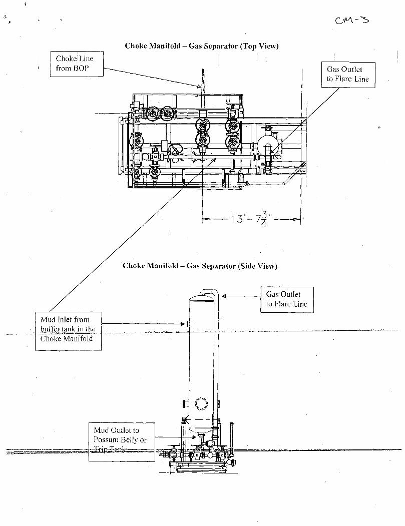
Choke! Line from BOP
Mud Inlet from buffer tank in the Choke Manifold
Choke Manifold - Gas Separator (Top View)
Choke Manifold - Gas Separator (Side View)
t c Mud Outlet to Possum Belly or
Gas Outlet to Flare Line
Gas Outlet to Flare Line
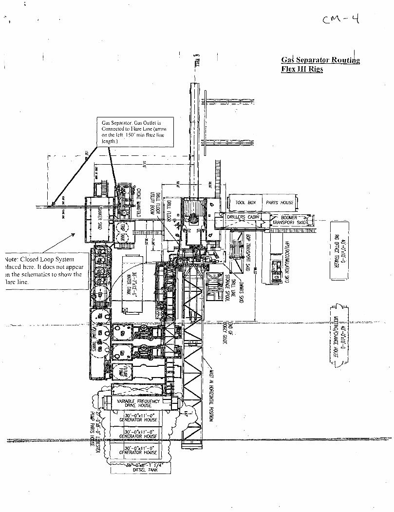
Gas Separator Routing Flex III Rigs
\Iote: Closed Loop System jlaced here. It does not appear m the schematics to show the lare line.
DIESEL TANK
Coflex Hose Certification
Fluid Technology
Quality Document
QUALITY CONTROL INSPECTION AND TEST CERTIFICATE
PURCHASER: Phoenix Beattie Co.
CERT. N s: 746
P.O. Ns: 002491
CONTTTECH ORDER N°: 412638 HOSE TYPE: 3" ID Choke and Kill Hose
HOSE SERIAL W: 52777 NOMINAL / ACTUAL LENGTH: 10,67 m
WP. 68,96 MPa 10000 Psi
Pressure lest with water at ambient temperature
T.P. 103,4 MPa 15000 psi Duration: 6 0 -
See attachment. (1 page)
mm.
t 10mm= 10 Mln.
-> 1Dmm= 25 MPa
COUPLINGS
Type Serial N° Quality HeatN*
3" coupling with
4 1/16'Flange end
917 913 AISI4130
AISI413Q
T7998A
26984
INFOCHIP INSTALLED
All metal parts are flawless
API Spec 16 C Temperature rate:"B" S
WE CERTIFY THAT THE ABOVE HOSE HAS BEEN MANUFACTURED IN ACCORDANCE WITH THE TERMS OF THE ORDER AND PRESSURE TESTED AS ABOVE WITH SATISFACTORY RESULT.
Coflex Hose Certification
Page: j / j
Coflex Hose Certification
Delivery Note
Form No 100/12
Phoenix Beattie Corp 115B Brfttwore Po* Drivt Houston. TX 77M1 Tel: (832) 327-0141 Fax: (832) 327-0W8 E-BS11 w1I$)ro«rtJltettle.a» v*«.phoer1)ieattte. a»
Customer Order Number 370-359-001 Delivery Note Number 003078 Page 1
Customer / invoice Address HELMERICH & PAYNE INT'L DRILLING CO 1437 SOUTH BOULDER TULSA. OK 74119
Delivery / Address HELMERICH & PAYNE IDC ATTN: JOE STEPHENSON - RIG 370 13609 INDUSTRIAL ROAD HOUSTON. TX 77015
Customer Acc No Phoenix Beattie Contract Manager Phoenix Beattie Reference Date
H01 JJL 006330 05/23/2008
item No
Beattie Part Number / Description Qty Ordered
Qty Sent
Qty To Follow
1
-2-
HP10CK3A-35-4F1 3° 10K 16C C&K HOSE X 35ft OAL CW 4.1/16" API SPEC FLANGE E/ End 1: 4.1/16" lOKp$1 API Spec 6A Type 6BX Flange End 2: 4.1/16" lOKpsi API Spec 6A Type 6BX Flange c/w BX155 Standard ring groove at each end Suitable for H2S Service Working pressure: 10.OOOpsi Test pressure: 15.000ps1 Standard: API 16C Full specification Armar Guarding: Included F1re Rating: Not Included Temperature rating: -20 Deg C to +1C0 Oeg C
1
SEGK3-HPF3 — 1 1
LIFTING & SAFETY EQUIPMENT TO SUIT HP10CK3-35-F1 2 x 160m 10 Safety Clamps 2 x 244fflm ID Lifting Collars & element C's 2 x 7ft Stainless Steel wire rope 3/4" 00 4 x 7.75t Shackles
SC725-200CS SAFETY CLAMP 200W 7.25T C/S GALVANISED
Continued...
All goods remain the property of Phoenix Beattie until paid for In full. Any damage or shortage on this delivery must be advised within 6 days. Returns may be subject to a handling charge.
Coflex Hose Cert i f ication Fr4 W
Form No 100/12
Phoenix Beattie Corp
eiivery
USB Brfttoorf Park Drive Houston. TX 77M1 Tel: (832) 327-0U1 • fix: (B32) 327-OMS E-ot11 Mll«phoent*e«tt1e.co« M*f.l*werrixSwtt1e.as
Customer Order Number 370-369-001 Delivery Note Number 003078 Page 2
Customer / Invoice Address HELMERICH & PAYNE INT'L DRILLING CO 1437 SOUTH BOULDER TULSA, OK 74119
Delivery / Address HELMERICH & PAYNE IDC ATTN: JOE STEPHENSON - RIG 370 13609 INDUSTRIAL ROAD HOUSTON. TX 77015
Customer Acc No Phoenix Beattie Contract Manager Phoenix Beattie Reference Date
HOI JJL 006330 05/23/2008
Item No
Beattie Part Number / Description
SC725-132CS
SAFETY CLAMP 132HM 7.25T C/S GALVANIZED C/W BOLTS
00CERT-HYDRO HYDROSTATIC PRESSURE TEST CERTIFICATE 00CERT-LOAD LOAD TEST CERTIFICATES
00FRE1GHT INBOUND / OUTBOUND FREIGHT PRE-PAY & ADD TO FINAL INVOICE NOTE: MATERIAL MUST BE ACCOMPMffiJLPAPERWORKJNaUOING. THE'PURCHASE "ORDER. RIG NUMBER TO ENSURE PROPER PAYMENT
Phoenix Beattie Inspection Signature :
Received in Good Condition : Signature
-Prim-Name-
Qty Ordered
Qty Sent
Qty To Follow
Date ' Ail goods remain the property of Phoenix Beattie until paid for ki tuft. Any damage or shortage on this delivery must be advised within 6 days. Returns may be subject to a handling charge.
it |
« ^ v P H | O E N I X B 6 a r f t t i e !• Material Identification Certificate
11 i: PA No | oc»e 330 | Client | HELMERICH & PAYNE INT'L DRlLLINq COent Ref ] 370-369-001 | Page | l
t Ii, . Part No | Description Material Desc 1; Material Spec Qty WO No Batch No Test Cert No Bin No Drg No Issue No
W10O3A-35-4n 3- 1 « 16C C« HOSE x 35Tt QAL I Z491 52777/H884 MATER
SECX3-HPF3 1 UFTIW & SAFETY EQUIPMENT TO k I 2440 002440 tt/STK
SC725-200CS 1 SAFETY CLAW 2OOW 7.IST CARBON STEEL U I 2519 H665 22C
SC72S-132CS 1 SAFETY CLAW 132W 7.25T CARBON STEEL l 2242 H139 22
I S> 1 1, i i: f h ! U 1 it 1 1,
1, ii
Ti
II Ii
II ii ti
ii il 11 !l it ' 11 'i 11 tj
! !
We hereby c »rtify that these goods have been inspected by our Quality Management System, and to the best of our knowledge are found to conform to relevant Industry standards within the requirements of the purchase order as issued to Phoenix Beattie Corporation.
Coflex Hose Certification
Fluid Technology
Quality Document
C E R T I F I C A T E OF C O N F O R M I T Y
Supplier : CONTITECH RUBBER INDUSTRIAL KFT. Equipment: 6 pes. Choke and Kill Hose with installed couplings Type: 3" x 10,67m WP: 10000psi Supplier File Number : 412638 Date of Shipment : April. 2008 Customer : Phoenix Beattie Co. Customer P.O. : 002491 Referenced Standards / Codes / Specifications: API Spec 16 C Serial No.: 52754,52755,52776,52777,52778,52782
STATEMENT OF CONFORMITY
We hereby certify that the above items/equipment supplied by us are in „cpnformjty_withJhe Purchaser Order and that these items/equipment were fabricated inspected and -tested in accordance with the referenced standards, codes and specifications arid meet the relevant acceptance criteria and design requirements.
COUNTRY OF ORIGIN HUNGARY/EU
-ofltflech Rubber Indus trial Eft.
Quality Control Dept oi Date: 04. April. 2008
Position: Q.C. Manager
Signed :
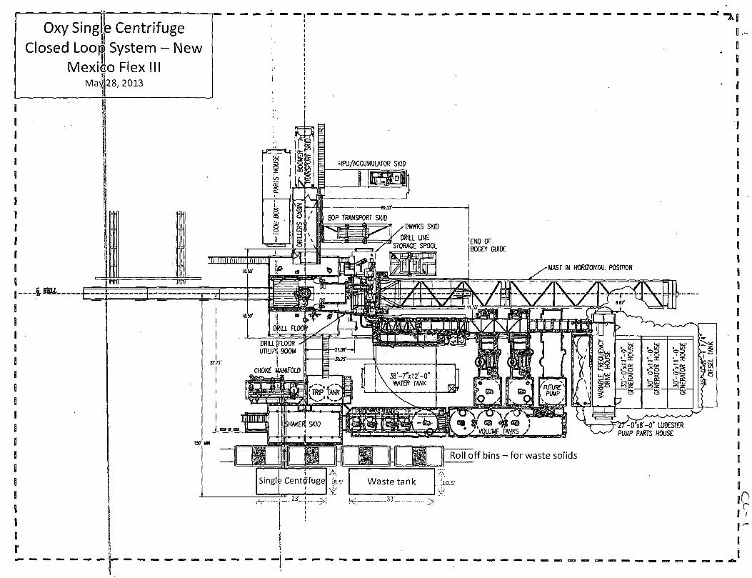
Oxy Singjje Centrifuge Closed Loo© System - New
Mexilo Flex III
L
—£.IELL
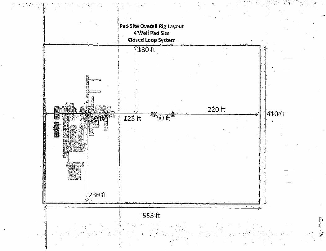
; Pad Site O vera IJ Rig Layout ; 4"Well Pad/Site
Closed Loop System
5SE f t •0
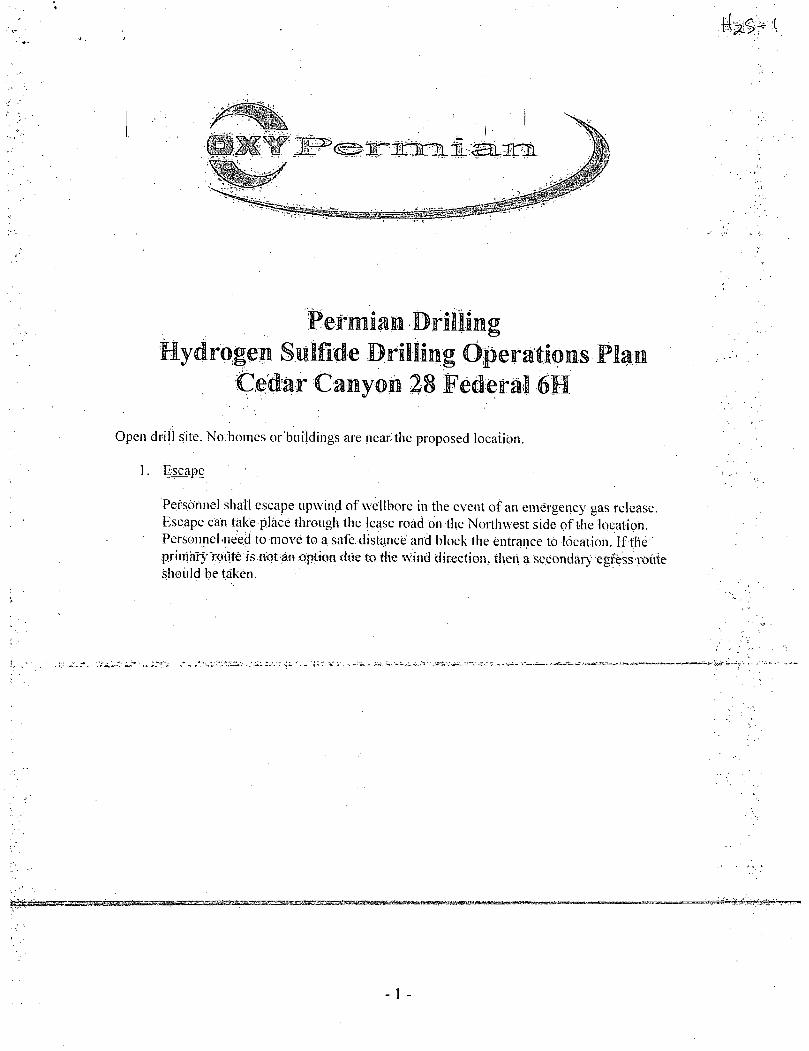
Hydrogeii Sulfide Drilling 'Operations Plan Ciedar Caiiyoii 28 Federal 6H
Open drill site. No homes or buildings are near the proposed location.
1. Escape
Personnel shall escape upw ind of wellbore in the event of an emergency gas release. Escape can take place through the lease road on the Northwest side of the location. Personnel .need to move to a safe distance and block the entrance to location. If the p.rimM5'lr ute1s.niLH:ain.cotton due to the wind direction, then a secondary 'egt&s-route should be taken.
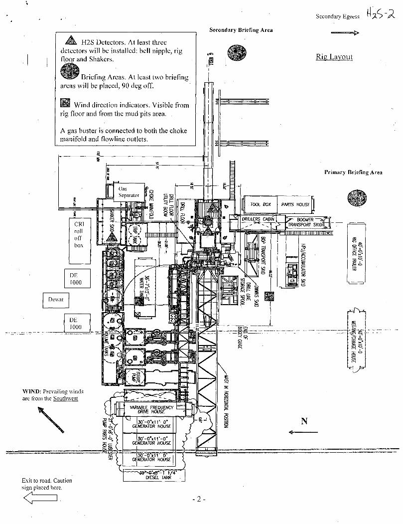
Secondary Egress
H2S Detectors. At least three detectors will be installed: bell nipple, rig floor and Shakers.
I iriefing Areas. At least two briefing areas will be placed, 90 deg off.
03 Wind direction indicators. Visible from rig floor and from the mud pits area. .
A gas buster is connected to both the choke manifold and flowline outlets.
Secondary Briefing Area
Rig Layout
Primary Briefing Area
CRI rol off box
DE 1000
Dewat
DE 1000
WIND: Prevailing winds are from the Southwest
Exit to road. Caution sign placed here.
Hydf.o:ge-ii Sulfide IMItiiig Operations .'Wan New Mexico
S.cop.e
This cMtMgehcy\plan -establishes .guidelines, for .the public, all company employees,, and contract employees who's work activities may involve exposure to hydrogen sulfide (IJ2S) gas: While drilling this well, it is possible to encounter H2S bearing formations. At all times: the first fr#i'iev to control M2S emissions m i l be the dnilfeg iMM. whi-eh will have a density high enough to control influx.
Qjfriee-'fec
iteo-\4fe-&h M2S is detected. All JI2S detections 'in .excess of i-8 partsper million (ppm) concentration are considered an Emergency.
. Prevent any and all accidents, and prevent the uncontrolled release of •hydrogen sulfide into the atmosphere.
Provide proper evacuation procedures to cope with .emergencies.
•Provide immediate and adequate medical attention should an injury occur.
Discussion
Implementation:
Emergency response Procedure:
Emergency equipment Procedure:
Training provisions:
Drilling emergency call lists:
Briefing:
Public safety:
This plan with all details is to be fully implemented before drilling to commence.
This section outlines the conditions and denotes steps to be taken in the event of an emergency.
This section outlines the safety and emergency equipment that will be required for the drilling of this well.
This section outlines the training provisions that must be adhered to prior to drilling.
Included are the telephone numbers of all persons to be contacted should an emergency exist.
This section deals with the briefing of all people involved in the drilling operation.
Public safety personnel will be made aware of any potential evacuation and any additional support needed.
Check lists:
"Generalinfo r mation:
Status check lists and procedural check lists have been included to insure adherence to the plan.
'A'general information s'ecfiorf has'been included to supply support information.
- 2 -
Hydrogen Sulfide Training
All personnel, whether regularly assigned, contracted, or employed on an unscheduled basis, will receive training from a qualified instructor in the following areas prior to commencing drilling operations on the well:
1. The hazards and characteristics of H2S. 2. Proper use and maintenance of personal protective equipment and life support
systems. 3. H2S detection. 4. Proper use of H2S detectors, alarms, warning systems, briefing areas, evacuation
procedures and prevailing winds. 5. Proper techniques for first aid and rescue procedures. 6. Physical effects of hydrogen sulfide on the human body. 7. Toxicity of hydrogen sulfide and sulfur dioxide. 8. Use of SCBA and supplied air equipment. 9. First aid and artificial respiration. 10. Emergency rescue.
In addition, supervisory personnel will be trained in the following areas:
1. The effects of H2S on metal components. If high tensile strength tubular is to be used, personnel will be trained in their special maintenance requirements.
2. Corrective action and shut-in procedures when drilling a well, blowout prevention and well control procedures.
3. The contents and requirements of the H2S Drilling Operations Plan.
H2S training refresher must have been taken within one_year prior4odrihingJhe^y£ll. "Specific?ornhe "wel 1 to"beHfilled wi 11 "be "3is^uisedliuring The"pre-spud meeting. H2S and well control (choke) drills will be performed while drilling the well, at least on a weekly basis. This plan shall be available in the well site. All personnel will be required to carry the documentation proving that the H2S training has been taken.
Service company and visiting personnel
A. Each service company that will be on this well will be notified if the zone contains H2S.
B Each service company must provide for the training and equipment of their employees before they arrive at the well site.
Each service company will be expected to attend a well site briefing
j Emergency Equipment Req'uirements j
1. Well control equipment
The well shall have hydraulic BOP equipment for the anticipated pressures. Equipment is to be tested on installation and follow Oxy Well Control standard, as well as BLM Onshore Order #2.
Special control equipment:
A. Hydraulic BOP equipment with remote control on ground. Remotely operated choke.
B. Rotating head C. Gas buster equipment shall be installed before drilling out of surface pipe.
2. Protective equipment for personnel
A. Four (4) 30-minute positive pressure air packs (2 at each briefing area) on location.
B. Adequate fire extinguishers shall be located at strategic locations.
C. Radio / cell telephone communication will be available at the rig.
Rig floor and trailers. Vehicle.
3. Hydrogen sulfide sensors and alarms
—A„. -HfS-serisDrwft^^ and at the flow line: These monitors will be set to alarm at 10 ppm with strobe light, and audible alarm.
B. Hand operated detectors with tubes. C. H2S monitor tester (to be provided by contract Safety Company.) D. There shall be one combustible gas detector on location at all times.
4. Visual Warning Systems
A. One sign located at each location entrance with the following language:
Caution - potential poison gas "Hydrogen sulfide No admittance without authorization
-4 -
Wind sock - wind streamers: [ j
A. One 36" (in length) wind sock located at protection center, at height visible from rig floor.
B. One 36" (in length) wind sock located at height visible from pit areas.
Condition flags
A. One each condition flag to be displayed to denote conditions.
green - normal conditions yellow - potential danger red - danger, H2S present
B. Condition flag shall be posted at each location sign entrance.
5. Mud Program
The mud program is designed to minimize the risk of having H2S and other formation fluids at surface. Proper mud weight and safe drilling practices will be applied. H2S scavengers will be used to minimize the hazards while drilling. Below is a summary of the drilling program.
Mud inspection devices:
Garrett gas train or hatch tester for inspection of sulfide concentration in mud system.
6. Metallurgy
A. Drill string, casing, tubing, wellhead, blowout preventers, drilling spools or adapters, kill lines, choke manifold, lines and valves shall be. suitable for the H2S service.
B. All the elastomers, packing, seals and ring gaskets shall be suitable for H2S service.
7. Well Testing
No drill stem tejtwill be performed on this well.
8. Evacuation plan
Evacuation routes should be established prior to well spud for each well and discussed with all rig personnel.
Designated area
A. Parking and visitor area: all vehicles are to be parked at a predetermined safe distance from the wellhead.
B. There will be a designated smoking area. C. Two briefing areas on either side of the location at the maximum
allowable distance from the well bore so they offset prevailing winds perpendicularly, or at a 45-degree angle if wind direction tends to shift in the area.
Emergency procedures
In the event of any evidence of H2S level above 10 ppm, take the following steps:
1. The Driller will pick up off bottom, shut down the pumps, slow down the pipe rotation.
2. Secure and don escape breathing equipment, report to the upwind designated safe briefing /• muster area.
3. All personnel on location will be accounted for and emergency search should begin for any missing, the Buddy System will be implemented.
4. Order non-essential personnel to leave the well site, order all essential personnel out of the danger zone and upwind to the nearest designated Safe-brieT^ "
5. Entrance to the location will be secured to a higher level than our usual "Meet and Greet" requirement, and the proper condition flag will be displayed at the entrance to the location.
6. Take steps to determine If the H2S level can be corrected or suppressed and, if so, proceed as required.
If uncontrollable conditions occur:
1. Take steps to protect and/or remove any public in the down-wind area from the rig - partial evacuation and isolation. Notify necessary. public safety personnel and appropriate regulatory entities (i.e. BLM) of the situation.
2. Remove all personnel to the nearest upwind designated safe briefing / muster area or off location.
3. Notify public safety personnel of safe briefing / muster area.
4. An assigned crew member will blockade the entrance to the location. No unauthorized personnel will be allowed entry to the location.
5. Proceed with best plan (at the time) to regain control of the well. Maintain tight security and safety procedures.
C. Responsibility:
1. Designated personnel.
a. Shall be responsible for the total implementation of this plan. b. Shall be in complete command during any emergency. c. Shall designate a back-up.
All personnel
Drill site manager:
2. 3. 4.
1.
2:
On alarm, don escape unit and report to the nearest upwind designated safe briefing / muster area upw Check status of personnel (buddy system). Secure breathing equipment. Await orders from supervisor.
Don escape unit if necessary-and report to nearest upwind designated safe briefing / muster area.
•Ce6fdffia1teJp^ to return to point of release with tool pusher and driller (using the buddy system). Determine H2S concentrations. Assess situation and take control measures.
Tool pusher: Don escape unit Report to up nearest upwind designated safe briefing / muster area. Coordinate preparation of individuals to return to point of release with tool pusher drill site manager (using the buddy system). Determine H2S concentration. Assess situation and take control measures.
Driller: Don escape unit, shut down pumps, continue
- 7 -
l4*S-rO
rotating DP. 2. Check monitor for point of release. 3. Report to nearest upwind designated safe briefing /
muster area. 4. Check status of personnel (in an attempt to rescue,
use the buddy system). 5. Assigns least essential person to notify Drill Site
Manager and tool pusher by quickest means in case of their absence.
6. Assumes the responsibilities of the Drill Site Manager and tool pusher until they arrive should they be absent.
Derrick man Floor man # 1 Floor man #2
.Will remain in briefing / muster area until instructed by supervisor.
Mud engineer: Report to nearest upwind designated safe briefing / muster area. When instructed, begin check of mud for ph and H2S level. (Garett gas train.)
Safety personnel Mask up and check status of all personnel and secure operations as instructed by drill site manager.
Taking a kick
When taking a kick during an H2S emergency, all personnel will follow standard Well control procedures after reporting to briefing area and masking up.
" ^Qpen hole io girrg"
All unnecessary personnel off floor. Drill Site Manager and safety personnel should monitor condition, advise status and determine need for use of air equipment.
Running casing or plugging
Following the same "tripping" procedure as above. Drill Site Manager and safety personnel should determine if all personnel have access to protective equipment.
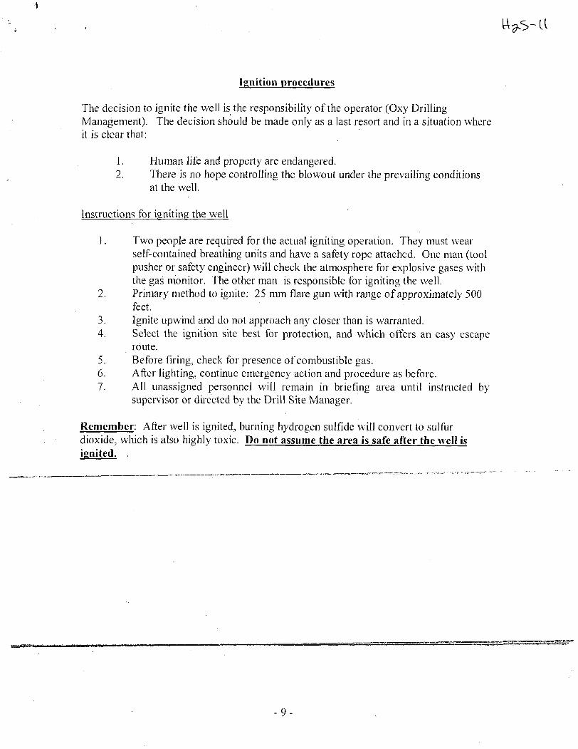
Ignition procedures
The decision to ignite the well is the responsibility of the operator (Oxy Drilling Management). The decision should be made only as a last resort and in a situation where it is clear that:
1. Human life and property are endangered. 2. There is no hope controlling the blowout under the prevailing conditions
at the well.
Instructions for igniting the well
1. Two people are required for the actual igniting operation. They must wear self-contained breathing units and have a safety rope attached. One man (tool pusher or safety engineer) will check the atmosphere for explosive gases with the gas monitor. The other man is responsible for igniting the well.
2. Primary method to ignite: 25 mm flare gun with range of approximately 500 feet.
3. Ignite upwind and do not approach any closer than is warranted. 4. Select the ignition site best for protection, and which offers an easy escape
route. 5. Before firing, check for presence of combustible gas. 6. After lighting, continue emergency action and procedure as before. 7. All unassigned personnel will remain in briefing area until instructed by
supervisor or directed by the Drill Site Manager.
Remember: After well is ignited, burning hydrogen sulfide will convert to sulfur dioxide, which is also highly toxic. Do not assume the area is safe after the well is ignited. .
V
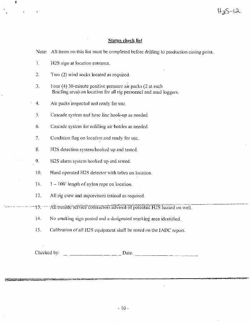
Status check list
Note: All items on this list must be completed before drilling to production casing point.
1. H2S sign at location entrance.
2. Two (2) wind socks located as required.
3. Four (4) 30-minute positive pressure air packs (2 at each Briefing area) on location for all rig personnel and mud loggers.
4. Air packs inspected and ready for use.
5. Cascade system and hose line hook-up as needed.
6. Cascade system for refilling air bottles as needed.
7. Condition flag on location and ready for use.
8. H2S detection system hooked up and tested.
9. H2S alarm system hooked up and tested.
10. Hand operated H2S detector with tubes on location.
11. 1-100' length of nylon rope on location.
12. All rig crew and supervisors trained as required.
"T3". Aird'u'tfifJe'service contractors advis^'bTpotential"H2S hazard on well.
14. No smoking sign posted and a designated smoking area identified.
15. Calibration of all FI2S equipment shall be noted on the I ADC report.
Checked by: Date:
- 10-
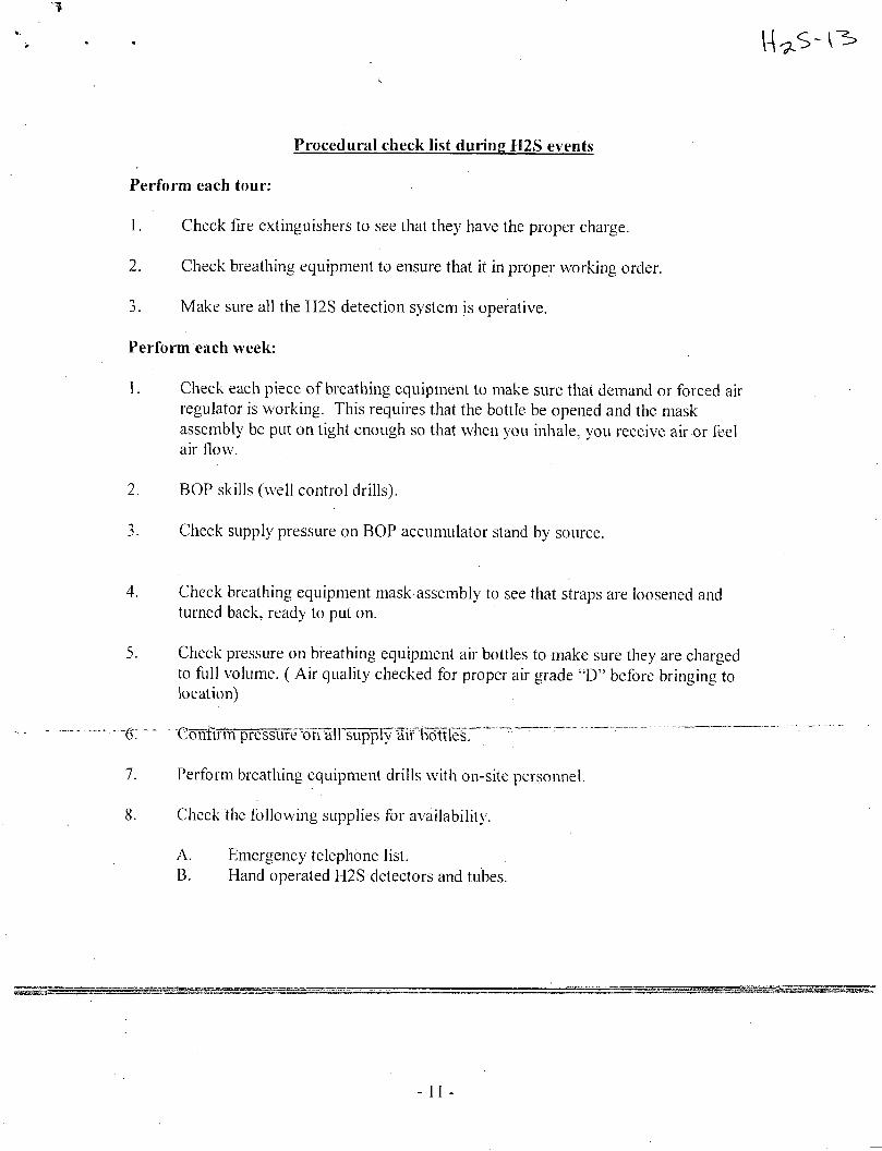
Procedural check list during H2S events
Perform each tour:
1. Check fire extinguishers to see that they have the proper charge.
2. Check breathing equipment to ensure that it in proper working order.
3. Make sure all the H2S detection system is operative.
Perform each week:
1. Check each piece of breathing equipment to make sure that demand or forced air regulator is working. This requires that the bottle be opened and the mask assembly be put on tight enough so that when you inhale, you receive air-or feel air flow.
2. BOP skills (well control drills).
3. Check supply pressure on BOP accumulator stand by source.
4. Check breathing equipment mask assembly to see that straps are loosened and turned back, ready to put on.
5. Check pressure on breathing equipment air bottles to make sure they are charged to full volume. ( Air quality checked for proper air grade "D" before bringing to location)
,g_ CoTJftrm pressure^ofTall ''su'pp"ly¥ir^ttle¥. " ~~~ "
7. Perform breathing equipment drills with on-site personnel.
8. Check the following supplies for availability.
A. Emergency telephone list. B. Hand operated H2S detectors and tubes.
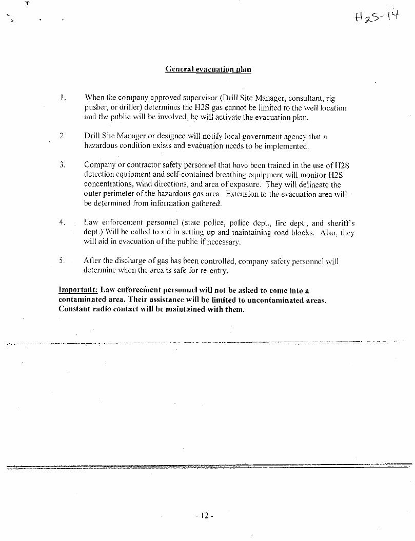
General evacuation plan
1. When the company approved supervisor (Drill Site Manager, consultant, rig pusher, or driller) determines the H2S gas cannot be limited to the well location and the public will be involved, he will activate the evacuation plan.
2. Drill Site Manager or designee will notify local government agency that a hazardous condition exists and evacuation needs to be implemented.
3. Company or contractor safety personnel that have been trained in the use of H2S detection equipment and self-contained breathing equipment will monitor H2S concentrations, wind directions, and area of exposure. They will delineate the outer perimeter of the hazardous gas area. Extension to the evacuation area will be determined from information gathered.
4. Law enforcement personnel (state police, police dept., fire dept., and sheriffs dept.) Will be called to aid in setting up and maintaining road blocks. Also, they will aid in evacuation of the public if necessary.
5. After the discharge of gas has been controlled, company safety personnel will determine when the area is safe for re-entry.
Important: Law enforcement personnel will not be asked to come into a contaminated area. Their assistance will be limited to uncontaminated areas. Constant radio contact will be maintained with them.
- 12-
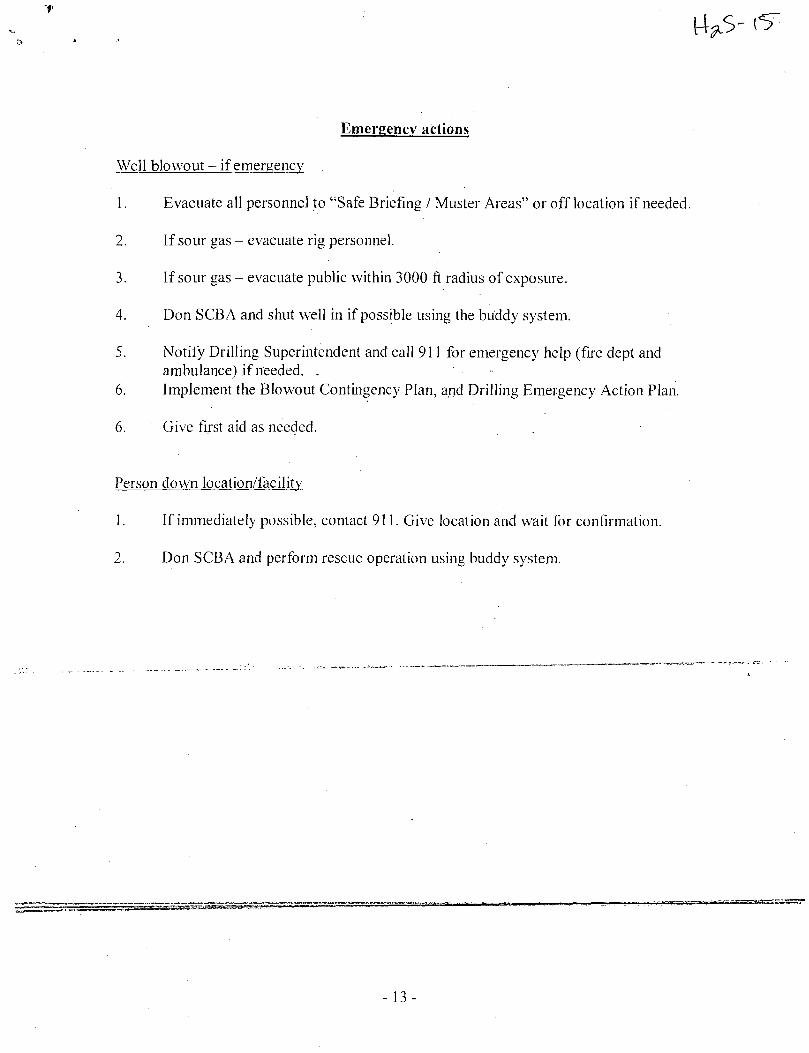
Emergency actions
Well blowout - i f emergency
1. Evacuate all personnel to "Safe Briefing / Muster Areas" or off location if needed.
2. If sour gas - evacuate rig personnel.
3. If sour gas - evacuate public within 3 000 ft radius of exposure.
4. Don SCBA and shut well in if possible using the buddy system.
5. Notify Drilling Superintendent and call 911 for emergency help (fire dept and ambulance) if needed. . •
6. Implement the Blowout Contingency Plan, and Drilling Emergency Action Plan.
6. Give first aid as needed.
Person down location/facility
1. If immediately possible, contact 911. Give location and wait for confirmation.
2. Don SCBA and perform rescue operation using buddy system.
- 13 -
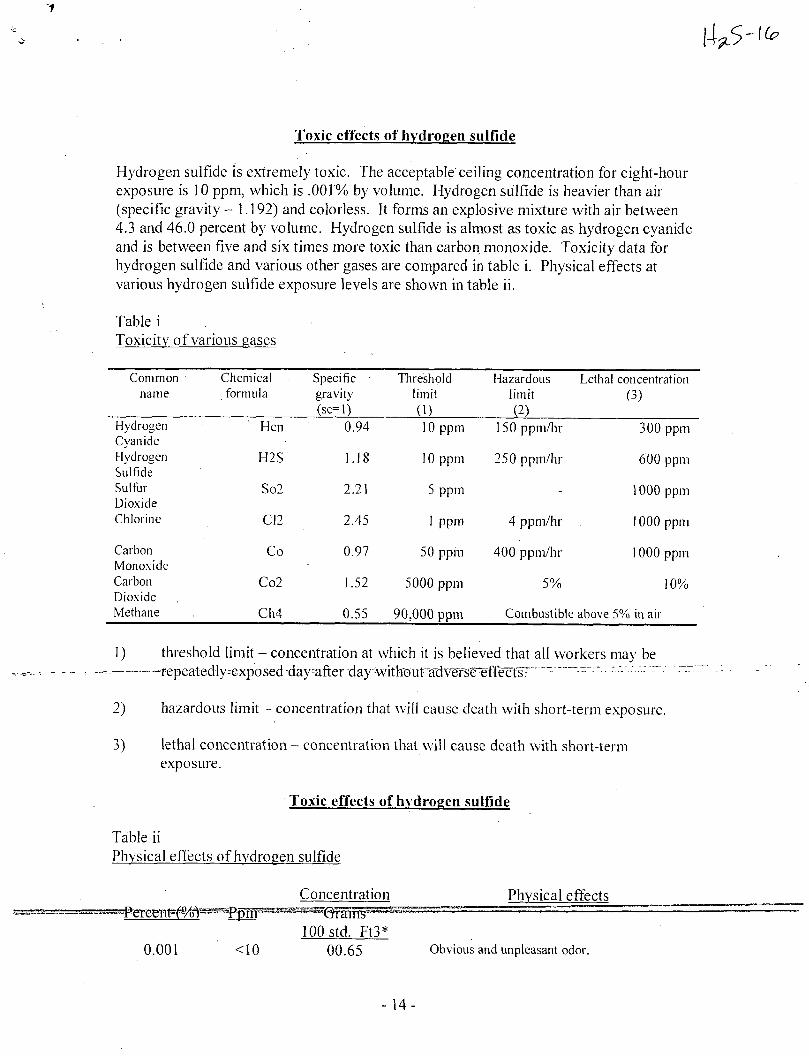
f
Toxic effects of hydrogen sulfide
Hydrogen sulfide is extremely toxic. The acceptable ceiling concentration for eight-hour exposure is 10 ppm, which is .001% by volume. Hydrogen sulfide is heavier than air (specific gravity -1.192) and colorless. It forms an explosive mixture with air between 4.3 and 46.0 percent by volume. Hydrogen sulfide is almost as toxic as hydrogen cyanide and is between five and six times more toxic than carbon monoxide. Toxicity data for hydrogen sulfide and various other gases are compared in table i . Physical effects at various hydrogen sulfide exposure levels are shown in table ii .
Table i Toxicity of various gases
Common Chemical Specific • Threshold Hazardous Lethal concentration name formula gravity limit limit (3)
(sc=l) (1) (2) Hydrogen Hen 0.94 10 ppm 150 ppm/hr 300 ppm Cyanide
300 ppm
Hydrogen H2S 1.18 10 ppm 250 ppm/hr 600 ppm Sulfide
250 ppm/hr 600 ppm
Sulfur So2 2.21 5 ppm - 1000 ppm Dioxide
1000 ppm
Chlorine C12 2.45 I ppm 4 ppm/hr 1000 ppm
Carbon Co 0.97 50 ppm 400 ppm/hr 1000 ppm Monoxide
1000 ppm
Carbon Co2 1.52 5000 ppm 5% 10% Dioxide
5000 ppm
Methane Ch4 0.55 90,000 ppm Combustible above 5% in air
1) threshold limit - concentration at which it is believed that all workers may be -. —..—r repeatedly^exposedday-after day'without ^
2) hazardous limit - concentration that will cause death with short-term exposure.
3) lethal concentration - concentration that will cause death with short-term exposure.
Toxic effects of hydrogen sulfide
Table ii Physical effects of hydrogen sulfide
Concentration Physical effects g ^ - ^ ^ P e r e ^ t ^ ^ s ^ -. •-
100 std. Ft3* 0.001 <10 00.65 Obvious and unpleasant odor.
- 14-
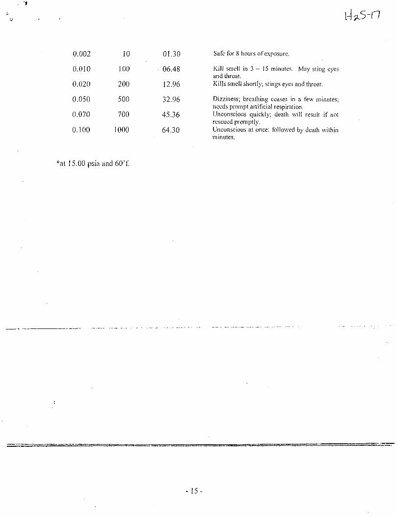
0.002 10 01.30
0.010 100 06.48
0.020 200 12.96
0.050 500 32.96
0.070 700 45.36
0.100 1000 64.30
Safe for 8 hours of exposure.
Kill smell in 3 - 15 minutes. May sting eyes and throat. Kills smell shortly; stings eyes and throat.
Dizziness; breathing ceases in a few minutes; needs prompt artificial respiration. Unconscious quickly; death will result i f not rescued promptly. Unconscious at once; followed by death within minutes.
*at 15.00 psia and 60'f.
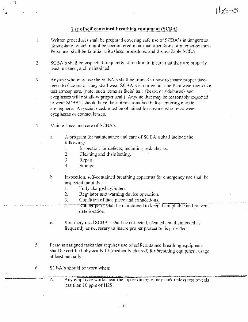
Use of self-contained breathing equipment (SCBA)
1. Written procedures shall be prepared covering safe use of SCBA's in dangerous atmosphere, which might be encountered in normal operations or in emergencies. Personnel shall be familiar with these procedures and the available SCBA.
2 SCBA's shall be inspected frequently at random to insure that they are properly used, cleaned, and maintained.
3. Anyone who may use the SCBA's shall be trained in how to insure proper face-piece to face seal. They shall wear SCBA's in normal air and then wear them in a test atmosphere, (note: such items as facial hair {beard or sideburns} and eyeglasses will not allow proper seal.) Anyone that may be reasonably expected to wear SCBA's should have these items removed before entering a toxic atmosphere. A special mask must be obtained for anyone who must wear eyeglasses or contact lenses.
4. Maintenance and care of SCBA's:
a. A program for maintenance and care of SCBA's shall include the following: 1. Inspection for defects, including leak checks. 2. Cleaning and disinfecting. 3. Repair. 4. Storage.
b. Inspection, self-contained breathing apparatus for emergency use shall be inspected monthly. 1. Fully charged cylinders. 2. Regulator and warning device operation. 3. Condition of face piece and connections.
- — 4:™RTibb^T]Wts^fiairbe maintaifIetlTo~keep therrTpliaWe^nd prevent deterioration.
c. Routinely used SCBA's shall be collected, cleaned and disinfected as frequently as necessary to insure proper protection is provided.
5. Persons assigned tasks that requires use of self-contained breathing equipment shall be certified physically fit (medically cleared) for breathing equipment usage at least annually.
6. SCBA's should be worn when:
X Any employee works near the top or on top of any tank unless test reveals less than 10 ppm of H2S.
- 16-
B. When breaking out any line where H2S can reasonably be expected.
C. When sampling air in areas to determine if toxic concentrations of H2S exists.
D. When working in areas where over 10 ppm H2S has been detected.
E. At any time there is a doubt as to the H2S level in the area to be entered.
Rescue First aid for H2S poisoning
Do not panic!
Remain calm - think!
1. Don SCBA breathing equipment.
2. Remove victim(s) utilizing buddy system to fresh air as quickly as possible, (go up-wind from source or at right angle to the wind. Not down wind.)
3. Briefly apply chest pressure - arm lift method of artificial respiration to clean the victim's lungs and to avoid inhaling any toxic gas directly from the victim's lungs.
4. Provide for prompt transportation to the hospital, and continue giving artificial respiration if needed.
5. Hf5spitai(s) or mediclflT^ beTofe-Hand, of the possibility of H2S gas poisoning - no matter how remote the possibility is.
6. Notify emergency room personnel that the victim(s) has been exposed to H2S gas.
Besides basic first aid, everyone on location should have a good working knowledge of artificial respiration.
Revised CM 6/27/2012
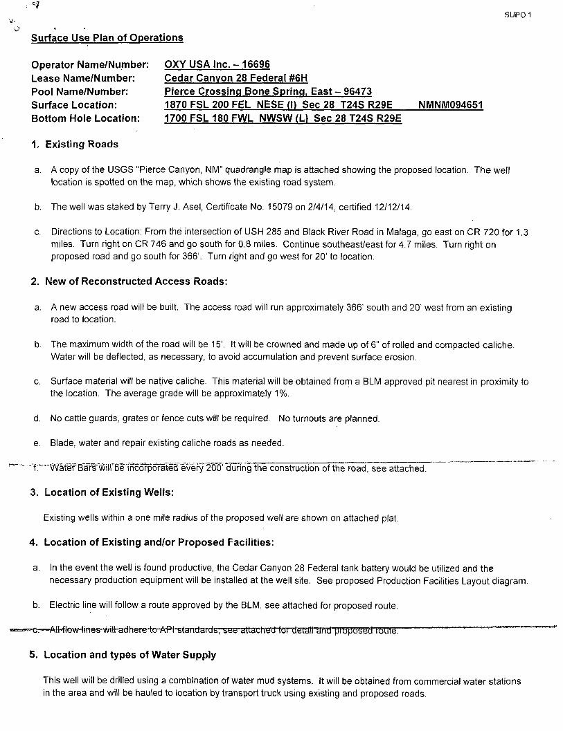
*7
Surface Use Plan of Operations
SUPO 1
Operator Name/Number: Lease Name/Number: Pool Name/Number: Surface Location: Bottom Hole Location:
1. Existing Roads
a. A copy of the USGS "Pierce Canyon, NM" quadrangle map is attached showing the proposed location. The well location is spotted on the map, which shows the existing road system.
b. The well was staked by Terry J. Asel, Certificate No. 15079 on 2/4/14, certified 12/12/14.
c. Directions to Location: From the intersection of USH 285 and Black River Road in Malaga, go east on CR 720 for 1.3 miles. Turn right on CR 746 and go south for 0.8 miles. Continue southeast/east for 4.7 miles. Turn right on proposed road and go south for 366'. Turn right and go west for 20' to location.
2. New of Reconstructed Access Roads:
a. A new access road will be built. The access road will run approximately 366' south and 20' west from an existing road to location.
b. The maximum width of the road will be 15'. It will be crowned and made up of 6" of rolled and compacted caliche. Water will be deflected, as necessary, to avoid accumulation and prevent surface erosion.
c. Surface material will be native caliche. This material will be obtained from a BLM approved pit nearest in proximity to the location. The average grade will be approximately 1%.
d. No cattle guards, grates or fence cuts will be required. No turnouts are planned.
e. Blade, water and repair existing caliche roads as needed.
-Y-"vVatITBaFs~^ of the road, see attached.
3. Location of Existing Wells:
Existing wells within a one mile radius of the proposed well are shown on attached plat.
4. Location of Existing and/or Proposed Facilities:
a. In the event the well is found productive, the Cedar Canyon 28 Federal tank battery would be utilized and the necessary production equipment will be installed at the well site. See proposed Production Facilities Layout diagram.
b. Electric line will follow a route approved by the BLM, see attached for proposed route.
' e ^AMrow^r res -w i l t edhe re^^ **" ----- ~
5. Location and types of Water Supply
OXY USA I n c . - 16696 Cedar Canyon 28 Federal #6H Pierce Crossing Bone Spring, East - 96473 1870 F S L 200 F E L N E S E (I) Sec 28 T24S R29E NMNM094651 1700 F S L 180 FWL NWSW (L) Sec 28 T24S R29E
This well will be drilled using a combination of water mud systems. It will be obtained from commercial water stations in the area and will be hauled to location by transport truck using existing and proposed roads.
SUP0 2
6. Construction Materials:
Primary
All caliche utilized for the drilling pad and proposed access road will be obtained from an existing BLM/State/Fee approved pit or from prevailing deposits found on the location. Will use BLM recommended extra caliche from other locations close by for roads, if available.
Secondary The secondary way of obtaining caliche to build locations and roads will be by "turning over" the location. This means, caliche will be obtained from the actual well site. A caliche permit will be obtained from BLM prior to pushing up any caliche. 2400 cubic yards is max amount of caliche needed for pad and roads. Amount will vary for each pad. The procedure below has been approved by BLM personnel: a. The top 6" of topsoil is pushed off and stockpiled along the side of the location. b. An approximate 120'X 120'area is used within the proposed well site to remove caliche. c. Subsoil is removed and piled alongside the 120' X 120' within the pad site. d. When caliche is found, material will be stockpiled within the pad site to build the location and road. e. Then subsoil is pushed back in the hole and caliche is spread accordingly across entire location and road. f. Once the well is drilled the stockpiled top soil will be used for interim reclamation and spread along areas where
caliche is picked up and the location size is reduced. Neither caliche nor subsoil will be stockpiled outside of the well pad. Topsoil will be stockpiled along the edge of the pad as depicted in the attached plat.
7. Methods of Handling Waste Material:
a. A closed loop system will be utilized consisting of above ground steel tanks and haul-off bins. Disposal of liquids, drilling fluids and cuttings will be disposed of at an approved facility. Solids-CRI, Liquids-Laguna
b. All trash, junk and other waste material will be contained in trash cages or bins to prevent scattering. When the job is completed, all contents will be removed and disposed of in an approved sanitary landfill.
c. The supplier, including broken sacks, will pickup slats remaining after completion of well.
d. A Porto-john will be provided for the rig crews. This equipment will be properly maintained during the drilling and completion operations and will be removed when all operations are complete.
e. Disposal of fluids to be transported will be by the following companies. TFH Ltd, Laguna SWD Facility
8. Ancil lary Facil i t ies: None needed.
9. Well Site Layout:
The proposed well site layout with dimensions of the pad layout and equipment location.
V-Door- East CL Tanks - North Pad - 410'X 505 ' - 4 wells
10. Plans for Surface Reclamation:
a After concluding the drilling and/or completion operations, if the well is found non-commercial.Ae.caliche,will.be„ removed from the pad and transported to the original caliche pit or used for other drilling locations. The road will be reclaimed as directed by the BLM. The original topsoil will again be returned to the pad and contoured, as close as possible, to the original topography, and the area will be seeded with an approved BLM mixture to re-establish vegetation.
SUPO 3
b. If the well is deemed commercially productive, caliche from the areas of the pad site not required for operations will be reclaimed. The original topsoil will be returned to the area of the drill pad not necessary to operate the well.
t These unused areas of the drill pad will be contoured, as close as possible, to match the original topography, and the area will be seeded with an approved BLM mixture to re-establish vegetation.
11. Surface Ownership:
The surface is owned by the U.S. Governmentand is administered by the BLM. The surface is multiple use with the primary uses of the region for the grazing of livestock and the production of oil and gas. The surface is leased to: Scott Branson, 1501 Mountain Shadow, Carlsbad, NM 88220. They will be notified of our intention to drill prior to any activity.
12. Other Information:
a. The vegetation cover is generally sparse consisting of mesquite, yucca, shinnery oak, sandsage and perennial native range grass. The topsoil is sandy in nature. Wildlife in the area is also sparse consisting of deer, coyotes, rabbits, rodents, reptiles, dove and quail.
b. There is no permanent or live water in the general proximity of the location.
c. There are no dwellings within one mile of the proposed well site.
d. Cultural Resources Examination - This well is located in the Permian Basin MOA. Pad + VS mile road $1507.00 Pipeline-up to 1 mile $1391.00 Electric Line-up to 1 mile $696.00 Total $3594.00
13. Bond Coverage:
$.19/ft over 1/4 mile $290 per % mile $.21/ftover 1 mile
$0.00 $0.00 $0.00
mm
$1507.00 $1391.00 $696.00
$3594.00
Bond coverage is lndividual-NMB000862, Nationwide-ESB00226.
14. Operators Representatives: The OXY Permian representatives responsible for ensuring compliance of the surface use plan are listed below:
Don Kendrick Production Coordinator 1502 West Commerce Dr. Carlsbad, NM 88220 Office-575-628-4132 Cellular-575-602-1484
Charles Wagner Manager Field Operations 1502 West Commerce Dr. Carlsbad, NM 88220 Office-575-628r4151 Cellular-575-725-8306
Calvin (Dusty) Weaver Operation Specialist P.O. Box 50250 Midland, TX 79710 Office - 432-685-5723 Cellular-806-893-3067
Omar Lisigurski RMT Leader P.O. Box 4294 Houston, TX 77210 Office-713-215-7506 Cellular-281-222-7248
0.0 '194'/' B.C.
20 I 21
1/4 CORNER GLO '1942' B.C.
DESCRIPTION
SURVEY FOR A SI RIP OF LAND 50.0 FEET V/lDE AND .4086.5 FEET OR 0.774 MILES IN LENGTH CROSSING USA LAND IN SECTION 28, TOWNSHIP 24 SOUTH, RANGE 29 EAST, N.M.P.M.. EDDY COUNTY, NEW MEXICO, AND BEING 25.0 FEET LEFT AND 25.0 FEET RIGHT OF 1HE ABOVE PLATTED CENTERLINE SURVEY.
GREEN - SURFACE 1459.9 FEET SURF- BATT- TO FEE. RED - BURIED 2626.6 FEET BURIED OUT OF FEE LAND TOTAL - 4086.5 FEET
NOTE BEARINGS SHOWN HEREON ARE MERCATOR GRID AND CONFORM TO THE NEW MEXICO COORDINATE SYSTEM "NEW MEXICO EAST ZONE-NORTH AMERICAN DATUM 1983. DISTANCES ARE SURFACE VALUES.
I, RONALD J. EIDSON, NEW MEXICO BRi DO HEREBY CERTIFY THAT THIS S j / W ...... 0N''THE GROUND UPON WHICH if ISTBASWi VfflE'PtrfEQtfMED BY ME OR UNDER MY DIRECT SUPERVISION THAT^$-RF$ltyNSIL%''',EOR THIS
LEGEND ® DENOTES. FOUND CORNER AS NOTED
fSJpNAL^SURVEYOR No. 3239. 'AT.Wfr/JlfcACTUAL SURVEY 1000
la; woo 2000 FEET
SURVEY: THAT THIS SURVEY fetf THmmMUMJs^NbAfiDS FOR SURVEWG IN NEW MEXICO: AWj TjTAT [T fe.ZRUB ANfy CORRECT TO THE BEST OF MY KNOWI.EDGE ^:BF.LIEF^ J \
RONALD J. EIDSON
Scgle:1"=1000;
OA if: __
1
T
PROVIDING SURVEYING SERVICES
SINCE 1946
JOI-TN WEST SURVEYING COMPANY 412 M. llflL PASO HOBOS, N.M. 88240
(575)393-311/ imivjwicbfe TllPlSe 10021000
SURVEY FOR A PIPELINE TO THE CEDAR CANYON 27 FED. MB, #7H
& FED. 28 MH, #711 CROSSING SECTION 28, TOWNSHIP24 SOUTH, RANGE 29 EAST, N.M.P.M.
EDDY COUNTY, NEW MEXICO
Survey Dole: 2/13/15 CAD Dole: 4/23/15 Drown By. LSI.
W.O. Mo.: 15130526 i Rev:
©!)R*nnrev.«Ki7o\?i)ii\OKv II.SA IHCVHUMIW-ROOT cmw CANYON'Mas IN SEC. ?S ws-wt
Rel. W.O.: 110231 Sheel 1 of 1
1/4 CORNER (?>-HO "no: B.C.
SPK. NAIL IN KOAD
21 I 22
i—
29
32
LINE BEARING DISTANCE
U S76'16'39"E 782.6'
L2 -S76'16'39"E 2125.3'
' L3 S00Vl'40"W 435.5'
L4 S89'59'07"E • 240.2'
L5 N89'58'43"E 240.2'
t6 S89'59'06"£ 240.0'
L7 S88'48'41"E 240.3'
.14+50.5
LAT.= 32.185765'H LONG.- 103.902364' N
37+35.8 END SURVEY AT CEDAR CANYON 28 FEDERAL f7H
33 GLO "
589-3126 W
3.C.
2647.1 1/4 CORNER
GLO. "1916" B.C.
S89'45'44"W 2651.6' 34 CI.O "I'M.?" B.C.
DESCRIPTION SURVEY FOR A STRIP Of LAND 50.0 FEET WIDE AND 4304.1 FEET OR 0.815 MILES IN LENGTH CROSSING USA LAND IN SECTION 28, TOWNSHIP 24 SOUTH. RANGE 29 EAST, N.M.P.M.. EDDY COUNTY, NEW MEXICO, AND BEING 25.0 FEET LEFT AND 25.0 FEET RIGHT OF THE ABOVE FLATTED CENTERLINE SURVEY.
GREEN- SURFACE 782.6 FEET RED- BURIED 3521.5 FEET TOTAL- 4304.1 FEET
NOTE
1) BEARINGS SHOWN HEREON ARE MERCATOR GRID'AND CONFORM TO WE NEW MEXICO COORDINATE SYS1EM "NEW MEXICO EAST ZONE-NORTH AMERICAN DATUM 1983. DISTANCES ARE SURFACE VALUES.
2) LATITUD£ AND LONGITUDE VALUES SHOWN HEREON ARE RELATIVE TO THE NORTH AMERICAN DATUM 1983 (NAD83).
RONALD J. EIDSON, NEW ^tc^ROI'i^SlQNAL SURVEYOR No. 3239, DO HEREBY CERTIFY THATfimS^jRVEY- PY/lT&ND THE ACTUAL SURVEY ON THE GROUND UPON JMIffl-tjE 8mD'W.Rf'''PERFORMED BY ME OR UNDER MY DIRECT SUP$RVlS.IO$?JHfiTA^ty RESPONSIBLE FOR THIS SURVEY; THAT THIS SURVEY MEfS THE 'MINIMUM STANDARDS FOR SURVEYING IN NEW M§mo'; AND MUlljlS TRUE'AND CORRECT TO THE BEST OF MY KNO0BGE AND BELIEF. : i? '
RONALD J. EIDSON
LEGEND
® DENOTES FOUND CORNER AS NOTED
1000 0 1000
Scale: 1"--=1000'
2000 FEET
DATE: __
.^mmo-O X Y ZJ.S.A. IJSIC
PROVIDING SURVIVING SERVICES
SINCE 1916
JOHN WEST SURVEYING COMPANY 412 N. DAL PASO HODHS, N.M. 68240
(575) 393-3117 mvw.jwsc.biz 18PIS* 10021000
SURVEY FOR AN ELECTRIC LINE TO THE CEDAR CAN YON 27 FED. #611, #7H
& FED. 28 #6H, #7H CROSSING SECTION 28, TOWNSHIP24 SOUTH, RANGE29 EAST, N.M.P.M.
EDDY COUNTY, NEW MEXICO
©D!I/.niHC\l.ora^l)\20l5\«Y U.S.A. IHCVJIXI-tniCLINI' I!) THE CEDAR CAMYOM V EEf
Survey Dole: 2/13/15
y^W.O. N o . T l 5 i M 5 2 5 T ^ ^ 4 / g 3 / i 5 ^
Drown By. LSL
Re). W.O.: 15110235 Sheet 1 o( 1
GLO "'.942' B.C.
20 I 21
29 28
1/4 CORNER GLO 'I'M?' B.C.
N89'48T5"E 5318.3'
SI'K NAIL IN ROAD
21 I 22 8>-
28 27
£5?
IQ±JZ± r.l. HI.
P.I. 2038'26" RT. )
i±mJ— P.I. 09W36" RT.
2iAL7 P.I. 65'45'29" LI H83 LEASE RD.
LL2JJ— P.I. .KU'tt" 1.1 BEGIN SURVEY AT THE ,, CEDAR CANYON 28 CTB. FENCE , / \
N88V7'37"E / \ 12.4.2'
r N5354 45 E
29 28 (.) ; r
32 33 S89'3>26 W 2647.1
ao '1342" B.C.
117.5'
NI5W29"W l937.irTH)
\ USA -<S>-
l wn nan a -j
f, «7ii 4- 1
N89'5I'34"E I \ 20.3'
NI412'S0'W iwsT7T/fT"
1/4 CORNER CIS) "WW" B.C.
S89'45'44"W 2651.6'
28 \ 27 &
33 34 CLO "1942" B.C.
DESCRIPTION
SURVEY FOR A SI RIP OF LAND 50.0 FEET WE AND 4086.5 FEET OR 0.774 MILES IN LENGTH CROSSING USA LAND IN SECTION 28, TOWNSHIP 24 SOUTH, RANGE 29-EAST, N.M.PM., EDDY COUNTY. NEW MEXICO. AND BEING 25.0 FEET LEFT AND.25.0 FEET RIGHT OF THE ABOVE PLATTED CENTERLINE SURVEY.
GREEN - SURFACE 1459.9 FEET RED - BURIED 2626.6 FEET TOTAL - 4086.5 FEET
SURF- BATT- TO FEE. BURIED OUT OF FEE LAND
NOTE
BEARINGS SHOWN HEREON ARE MERCA10R GRID AND CONFORM TO THE NEW MEXICO COORDINATE SYSTEM "NEW MEXICO EAST ZONE-NORTH AMERICAN DATUM 1983. DISTANCES ARE SURFACE VALUES.
I. RONALD J. EIDSON, HEW MEXICOJ OSSSipNAClSURVEYOR No. 3239, DO HEREBY CERTIFY THAT THIS S0Rff i%ff l -ANW$B ACTUAL SURVEY ON THE GROUND UPON VMtCH i f I S ^ A S m \)m''P£RlspRMED'BY ME OR UNDER MY DIRECT SUPERVISION THA~T»M-RI"§ltyNStm'fOR THIS SURVEY; THAT THIS SURVEY /JEMS' THE/MlimiUM(SUNMOS FOR SURVEYING IN NEW MEXICO; fylETHAT FT75?.T(?(Jff AND CORRECT TO THE BEST OF MY KNOWLEDGE f ^ ' # ' " « ^ y I cc /
RONALD J. ODSONsL^Jw^^L^jkdfd^i
LEGEND
% DENOTES. FOUND CORNER AS NOTED
1000 0 &rJB'3SLZE£33Z
1000 = j —
2000 FEET
Scale; 1"-1000'
OXY U.S.A. nsro. OA1E: QMlMLm^S^^.
1
T
PROVIDING SURVT:YING SERVICES SINCE 1940
JOHN WEST SUR VEYTNG COMP A NY 412 N. DAL PASO HOBBS, N.M. 88240
(575)393-3117 wwwjwuMz IDPLSIl 10021000 •
SUR VEY FOR A PIPELINE TO THE CEDAR CANYON 27 FED. #6H, #711
& FED. 28 #611, #7H CROSSING SECTION 28. TOWNSHIP24 SOUTH, RANGE29 EAST, N.M.P.M.
EDDY COUNTY', NEW- MEXICO
Survey Date: 2/13/15 CAD Dole: 4/23/15 Drown By: I.St.
W.O. No.: 15130526 1 Rev:
©nsAnnjc\L(»cwo\20i5\o>:v u.s.* M\PiPaiHr.\K -nouir aim CAHYON was IN stc. 'a ?AS-m
Rel. W.O.: 15110234 Sheet 1 of
20
29
ao '1942" B.C.
21 N89'48'15"E 5318.5' 21 SPK. NAIL IN ROAD
22
•28 5
28/ 27
as
X
a; £
1/4 CORNER ®-aO '1942' B.C.
29
32
T907.T ("V
LINE TABLE
LINE BEARING DISTANCE
LI S76'I6'39"E 782.6'
L2 576'16'39'E 2125.3'
L3 S00V1'40"W 435.5'
L4 S89'59'07"E- 240.2'
L5 N89'58'43"E 240.2' .
1.6 SB9'59'06"E 240.0'
i 17 S88-48'41"E 240.3'
o o ^ t> Q rvj a3 + + +-••-*-+ +
\ o o «M *n w> aa
Ji+25.6
J4+50.5
rrf LEFT ro CEDAR CANYON 27 FEDERAL /SH LAT.= 32.186369' N L0NG.= 103.98236V N TEE LEFT TO CEDAR CANYON 28 FEDERAL (6H MT.= 32186232'N LONG- 103.982362-N TEE LEFT TO CEDAR CANYON 27 FEDERAL I7H LAl= 32.185889-N L0NC.= 103.982363-N P.I. 88-50'21' LT.
N06-42'18"W
LAT- 32.185765-N LONG* 103.982364-N ENO SURVEY AT CEDAR CANYON 28 FEDERAL }7H
'1706.2' (TIE)'
28 USA 28 -®-
33 GLO "1942'
S89-31"26"W 2647.1'
B.C.
1/4 CORNER ao '1916" B.C.
S89'45'44"W 2651.6'
27
33 I 34 ao '1942" B.C.
DESCRIPTION
SURVEY FOR A STRIP OF LAND 50.0 FEET WIDE AND 4304.1 FEET OR 0.815 MILES IN LENGTH CROSSING USA LAND IN SECTION 28. TOWNSHIP 24 SOUTH, RANGE 29 EAST, NMPM., EDDY COUNTY, NEW MEXICO, AND BEING 25.0 FEET LEFT AND 25.0 FEET RIGHT OF THE ABOVE PLATTED CENTERLINE SURVEY.
GREEN- SURFACE 782.6 FEET RED- BURIED 3521.5 FEET TOTAL- 4304.1 FEET
NOTE
1) BEARINGS SHOWN HEREON ARE MERCA10R GRID AND CONFORM TO THE NEW MEXICO COORDINATE SYSTEM "NEW MEXICO EAST ZONE" NORTH AMERICAN DATUM,1983. DISTANCES ARE SURFACE VALUES.
2) LATITUDE AND LONGITUDE VALUES SHOWN HEREON ARE RELATIVE • TO THE NORTH AMERICAN DA TUM 1983 (NAD83).
LEGEND
® DENOTES FOUND CORNER AS NOTED
SURVEYOR No. 3239, THE ACTUAL SURVEY
ME OR
/, RONALD J. EIDSON. NEW MEKCOJ ROFESSIONAL : 00 HEREBY. CERTIFY THAIjTO/S' SlWVEY. J}H£T'^AND ON THE GROUND UPON J/MtpH'iTJS B' jp'-WERf'/PERFORMED BY Ml UNDER MY DIRECT SUPlRVISfi^HA-T-CAy. RESPtySIBLE FOR THIS SURVEY; THAT THIS SdRM* ME TS THE MINIMUM STANDARDS FOR SURVEYING IN NEW M&lfib;, AN& TWTSlTjlS 'TRUE 'AND CORRECT TO THE BEST OF MY KNOtfLWGE ANL\8ELIET. ' *~ 1
WOO j-1 M M~l=r-
1000
Scale:!'=1000'
2000 FEET 1
RONALD J. EIDSON^
DATE:
O X Y U . S . A . I N C .
PROVIDING SURVEYING SERVICES "\ SINCE 1946
JOHN WEST SURVEYING COMPANY 412 N.'DAL PASO HOBBS, N.M. 8B240
(S7S) 393-3117 www.jwx.biz TBPLS* 10021000 _*AJ
SUR VEY FOR AN ELECTRIC LINE TO THE CEDAR CANYON 27 FED. #611, #7H
& FED. 28 #6H, #7H CROSSING SECTION 28, TOWNSHIP 24 SOUTH, RANGE 29 EAST, N.M.P.M.
EDDY COUNTY, NEW MEXICO
Survey Dole: 2/13/15 CAD Dote: 2/16/15 Drown By: LSL
W.O. No.': 15130525 Rev: .4/23/15 Rel. W.O.: 15110235
© 0RAniNG\lweMo\?0l5\OXY U.S.A. INCNELECIRIOJMt 10 THE CEDAR CANYON 27 FEE
Sheet 1 of 1
PECOS DISTRICT CONDITIONS OF APPROVAL
OPERATOR'S NAME: OXY USA, Inc LEASE NO.: NMNM94651.
WELL NAME & NO.: Cedar Canyon 28 Federal 6H SURFACE HOLE FOOTAGE: 18707S &2007E
BOTTOM HOLE FOOTAGE 17007S& 1807W LOCATION: Section 28, T.24 S., R.29 E., NMPM
COUNTY: Eddy County, New Mexico
T A B L E O F C O N T E N T S Standard Conditions of Approval (COA) apply to this APD. If any deviations to these
standards exist or special COAs are required, the section with the deviation or requirement will be checked below.
I I General Provisions I I Permit Expiration I I Archaeology, Paleontology, and Historical Sites I I Noxious Weeds ^ Special Requirements
, Cave/Karst VRM
I I Construction Notification Topsoil Closed Loop System Federal Mineral Material Pits Well Pads Roads
I I Road Section Diagram (XI Drilling
Cement Requirements Medium Cave/Karst Logging Requirements Waste Material and Fluids
I I Production (Post Drilling) Well Structures & Facilities Pipelines Electric Lines
I I Interim Reclamation I I Final Abandonment & Reclamation
Page 1 of29
I. GENERAL PROVISIONS
The approval of the Application For Permit To Drill (APD) is in compliance with all applicable laws and regulations: 43 Code of Federal Regulations 3160, the lease terms, Onshore Oil and Gas Orders, Notices To Lessees, New Mexico Oil Conservation Division (NMOCD) Rules, National Historical Preservation Act As Amended, and instructions and orders of the Authorized Officer. Any request for a variance shall be
1 submitted to the Authorized Officer on Form 3160-5, Sundry Notices and Report on Wells.
I I . PERMIT EXPIRATION .
If the permit terminates prior to drilling and drilling cannot be commenced within 60 days after expiration, an operator is required to submit Form 3160-5, Sundry Notices and Reports on Wells, requesting surface reclamation requirements for any surface disturbance. However, i f the operator will be able to initiate drilling within 60 days after the expiration of the permit, the operator must have set the conductor pipe in order to
. allow for an extension of 60 days beyond the expiration date of the APD. (Filing of a Sundry Notice is required for this 60 day extension.)
III. ARCHAEOLOGICAL, PALEONTOLOGY & HISTORICAL SITES
Any cultural and/or paleontological resource discovered by the operator or by any person working on the operator's behalf shall immediately report such findings to the Authorized Officer. The operator is fully accountable for the actions of their contractors and subcontractors. The operator shall suspend all operations in the immediate area of such discovery until written authorization to proceed is issued by the Authorized Officer. An evaluation of the discovery shall be made by the Authorized Officer to determine the appropriate actions that shall be required to prevent the loss of significant cultural or scientific values of the discovery. The operator shall be held responsible for the cost of the proper mitigation measures that the Authorized Officer assesses after consultation with the operator on the evaluation and decisions of the discovery. Any unauthorized collection or disturbance of cultural or paleontological resources may result in a shutdown order by the Authorized Officer.
IV. NOXIOUS WEEDS
The operator shall be held responsible i f noxious weeds become established within the areas of operations. Weed control shall be required on the disturbed land where noxious weeds exist, which includes the roads, pads, associated pipeline corridor, and adjacent land affected by the establishment of weeds due to this action. The operator shall consult with the Authorized Officer for acceptable weed control methods, which include following EPA and BLM requirements and policies.
Page 2 of29
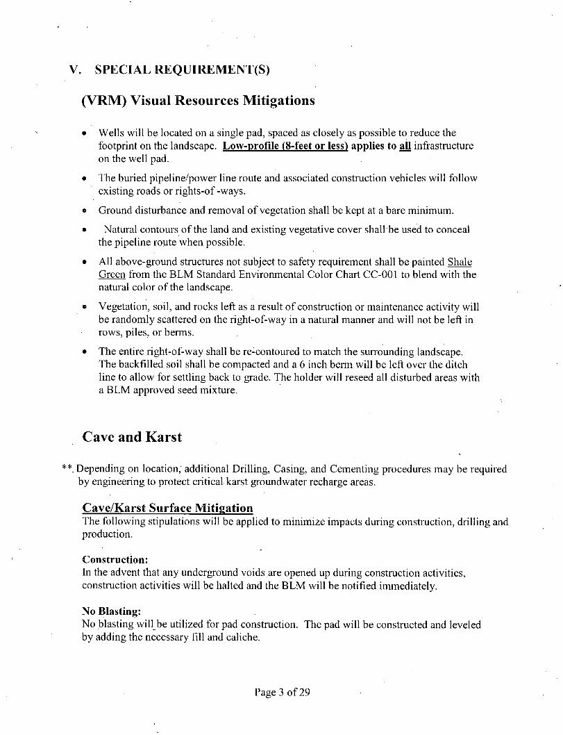
V. SPECIAL REQUIREMENT(S)
(VRlYi) Visual Resources Mitigations
• Wells will be located on a single pad, spaced as closely as possible to reduce the footprint on the landscape. Low-profile (8-feet or less) applies to all infrastructure on the well pad.
• The buried pipeline/power line route and associated construction vehicles will follow existing roads or rights-of -ways.
« Ground disturbance and removal of vegetation shall be kept at a bare minimum.
• Natural contours of the land and existing vegetative cover shall be used to conceal the pipeline route when possible.
• All above-ground structures not subject to safety requirement shall be painted Shale Green from the BLM Standard Environmental Color Chart CC-001 to blend with the natural color of the landscape.
• Vegetation, soil, and rocks left as a result of construction or maintenance activity will be randomly scattered on the right-of-way in a natural manner and will not be left in rows, piles, or berms.
• The entire right-of-way shall be re-contoured to match the surrounding landscape. The backfilled soil shall be compacted and a 6 inch berm will be left over the ditch line to allow for settling back to grade. The holder will reseed all disturbed areas with a BLM approved seed mixture.
Cave and Karst
**. Depending on location; additional Drilling, Casing, and Cementing procedures may be required by engineering to protect critical karst groundwater recharge areas.
Cave/Karst Surface Mitigation The following stipulations will be applied to minimize impacts during construction, drilling and production.
Construction: In the advent that any underground voids are opened up during construction activities, construction activities will be halted and the BLM will be notified immediately.
No Blasting: No blasting will be utilized for pad construction. The pad will be constructed and leveled by adding the necessary fill and caliche.
Page 3 of29
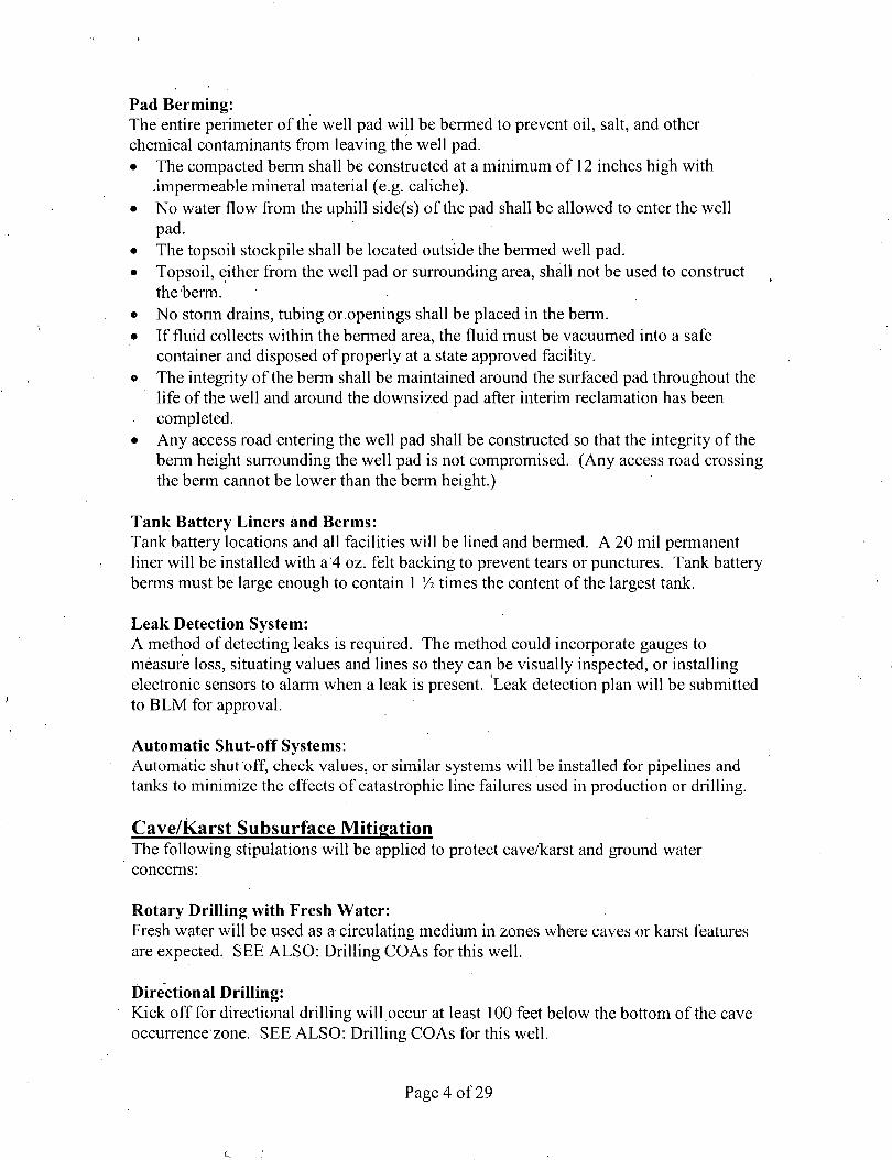
Pad Berming: The entire perimeter of the well pad will be bermed to prevent oil, salt, and other chemical contaminants from leaving the well pad. • The compacted berm shall be constructed at a minimum of 12 inches high with
.impermeable mineral material (e.g. caliche). • No water flow from the uphill side(s) of the pad shall be allowed to enter the well
pad. • The topsoil stockpile shall be located outside the bermed well pad. • Topsoil, either from the well pad or surrounding area, shall not be used to construct
the berm. • No stonn drains, tubing or.openings shall be placed in the berm. • If fluid collects within the bermed area, the fluid must be vacuumed into a safe
container and disposed of properly at a state approved facility. o The integrity of the berm shall be maintained around the surfaced pad throughout the
life of the well and around the downsized pad after interim reclamation has been completed.
• Any access road entering the well pad shall be constructed so that the integrity of the berm height surrounding the well pad is not compromised. (Any access road crossing the berm cannot be lower than the berm height.)
Tank Battery Liners and Berms: Tank battery locations and all facilities will be lined and bermed. A 20 mil permanent liner will be installed with a 4 oz. felt backing to prevent tears or punctures. Tank battery berms must be large enough to contain 1 I/2 times the content of the largest tank.
Leak Detection System: A method of detecting leaks is required. The method could incorporate gauges to measure loss, situating values and lines so they can be visually inspected, or installing electronic sensors to alarm when a leak is present. Leak detection plan will be submitted to BLM for approval.
Automatic Shut-off Systems: Automatic shut off, check values, or similar systems will be installed for pipelines and tanks to minimize the effects of catastrophic line failures used in production or drilling.
Cave/Karst Subsurface Mitigation The following stipulations will be applied to protect cave/karst and ground water concerns:
Rotary Drilling with Fresh Water: Fresh water will be used as a circulating medium in zones where caves or karst features are expected. SEE ALSO: Drilling COAs for this well.
Directional Drilling: Kick off for directional drilling will occur at least 100 feet below the bottom of the cave occurrence zone. SEE ALSO: Drilling COAs for this well.
Page 4 of29
Lost Circulation: ALL lost circulation zones from the surface to the base of the cave occurrence zone will be logged and reported in the drilling report.
Regardless of the type of drilling machinery used, i f a void of four feet or more and circulation losses greater than 70 percent occur simultaneously while drilling in any cave-bearing zone, the BLM will be notified immediately by the operator. The BLM will assess the situation and work with the operator on corrective actions to resolve the problem.
Abandonment Cementing: Upon well abandonment in high cave karst areas additional plugging conditions of approval may be required. The BLM will assess the situation and work with the operator to ensure proper plugging of the wellbore.
Pressure Testing: Annual pressure monitoring will be performed by the operator on all casing annuli and reported in a sundry notice. If the test results indicated a casing failure has occurred, remedial action will be undertaken to correct the problem to the BLM's approval.
Page 5 of29
VI. CONSTRUCTION
A. NOTIFICATION
The BLM shall administer compliance and monitor construction of the access road and well pad. Notify the Carlsbad Field Office at (575) 234-5909 at least 3 working days prior to commencing construction of the access road and/or well pad.
When construction operations are being conducted on this well, the operator shall have the approved APD and Conditions of Approval (COA) on the well site and they shall be made available upon request by the Authorized Officer.
B. TOPSOIL
The operator shall strip the top portion of the soil (root zone) from the entire well pad area and stockpile the topsoil along the edge of the well pad as depicted in the APD. The root zone is typically six (6) inches in depth. All the stockpiled topsoil will be redistributed over the interim reclamation areas. Topsoil shall not be used for berming the pad or facilities. For final reclamation, the topsoil shall be spread over the entire pad area for seeding preparation.
Other subsoil (below six inches) stockpiles must be completely segregated from the topsoil stockpile. Large rocks or subsoil clods (not evident in the surrounding terrain) must be buried within the approved area for interim and final reclamation.
C. CLOSED LOOP SYSTEM
Tanks are required for drilling operations: No Pits.
The operator shall properly dispose of drilling contents at an authorized disposal site.
D. FEDERAL MINERAL MATERIALS PIT
Payment shall be made to the BLM prior to removal of any federal mineral materials. .. Call the Carlsbad Field Office at (575) 234-5972.
E. WELL PAD SURFACING
Surfacing of the well pad is not required.
If the operator elects to surface the well pad, the surfacing material may be required to be removed at the time of reclamation.The well pad shall be constructed in a manner which creates the smallest possible surface disturbance, consistent with safety and operational needs.
F. EXCLOSURE FENCING (CELLARS & PITS)
Page 6 of29
Exclosure Fencing The operator will install and maintain exclosure fencing for all open well cellars to prevent access to public, livestock, and large forms of wildlife before and after drilling operations until the pit is free of fluids and the operator initiates backfilling. (For examples of exclosure fencing design, refer to BLM's Oil and Gas Gold Book, Exclosure Fence Illustrations, Figure 1, Page 18.)
G. ON LEASE ACCESS ROADS
Road Width The access road shall have a driving surface that creates the smallest possible surface disturbance and does not exceed fourteen (14) feet in width. The maximum width of surface disturbance, when constructing the access road, shall not exceed twenty-five (25) feet.
Surfacing Surfacing material is not required on the new access road driving surface. If the operator elects to surface the new access road or pad, the surfacing material may be required to be removed at the time of reclamation.
Where possible, no improvements should be made on the unsurfaced access road other than to remove vegetation as necessary, road irregularities, safety issues, or to fill low areas that may sustain standing water.
The Authorized Officer reserves the right to require surfacing of any portion of the access road at any time deemed necessary. Surfacing may be required in the event the road deteriorates, erodes, road traffic increases, or it is determined to be beneficial for future field development. The surfacing depth and type of material will be determined at the time of notification.
Crowning Crowning shall be done on the access road driving surface. The road crown shall have a grade of approximately 2% (i.e., a 1" crown on a 14' wide road). The road shall conform to Figure 1; cross section and plans for typical road construction.
Ditching
Ditching shall be required on both sides of the road.
Turnouts Vehicle turnouts shall be constructed on the road. Turnouts shall be intervisible with interval spacing distance less than 1000 feet. Turnouts shall conform to Figure 1; cross section and plans for typical road construction.
Drainage
Page 7 of29
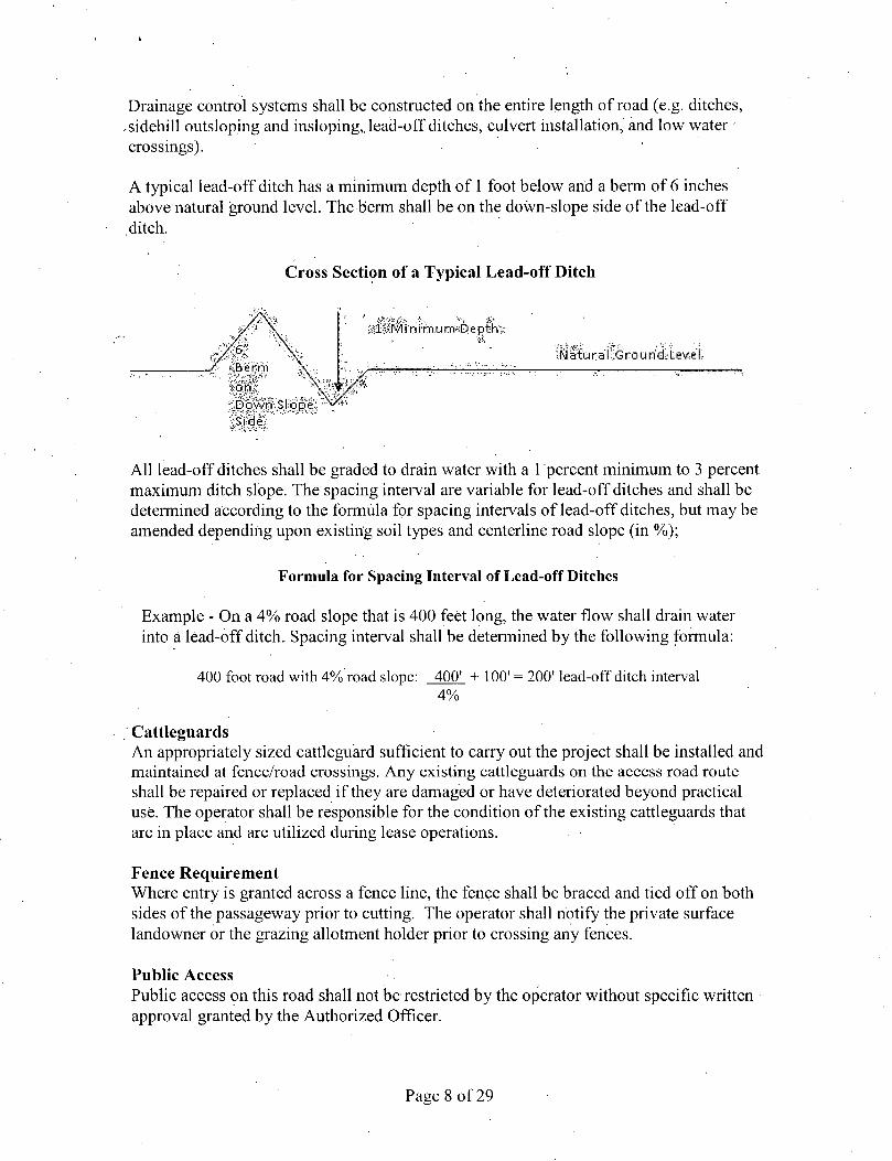
Drainage control systems shall be constructed on the entire length of road (e.g. ditches, ,sidehill outsloping and insloping,, lead-off ditches, culvert installation, and low water • crossings).
A typical lead-off ditch has a minimum depth of 1 foot below and a berm of 6 inches above natural ground level. The berm shall be on the down-slope side of the lead-off ditch.
Cross Section of a Typical Lead-off Ditch
afer?l i:Oi?m.u m'stEfe p t fe :Natu ra'f Grou rid. Lev e l
:,Dbwn,Sl;ope: Side
All lead-off ditches shall be graded to drain water with a 1 percent minimum to 3 percent maximum ditch slope. The spacing interval are variable for lead-off ditches and shall be determined according to the formula for spacing intervals of lead-off ditches, but may be amended depending upon existing soil types and centerline road slope (in %);
Formula for Spacing Interval of Lead-off Ditches
Example - On a 4% road slope that is 400 feet long, the water flow shall drain water into a lead-off ditch. Spacing interval shall be determined by the following formula:
400 foot road with 4% road slope: 400' + 100' = 200' lead-off ditch interval 4%
Cattleguards An appropriately sized cattleguard sufficient to carry out the project shall be installed and maintained at fence/road crossings. Any existing cattleguards on the access road route shall be repaired or replaced if they are damaged or have deteriorated beyond practical use. The operator shall be responsible for the condition of the existing cattleguards that are in place and are utilized during lease operations.
Fence Requirement Where entry is granted across a fence line, the fence shall be braced and tied off on both sides of the passageway prior to cutting. The operator shall notify the private surface landowner or the grazing allotment holder prior to crossing any fences.
Public Access Public access on this road shall not be restricted by the operator without specific written approval granted by the Authorized Officer.
Page 8 of 29
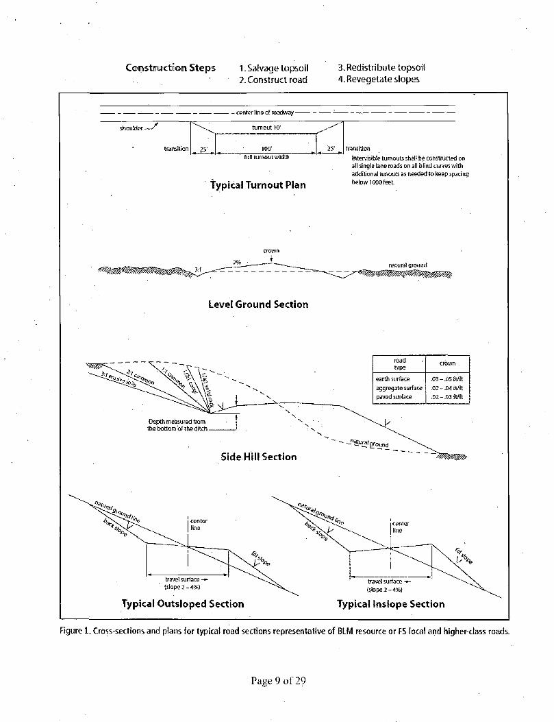
Coirtistruetioin Steps 1. Salvage topsoil 2. Construct road
3. Redistribute topsoil 4. Revegetate slopes
• - center line of roadway -
shoulder—' turnout 10"
transition 25' 100* '25 transition full turnout width
typical Turnout Plan
intervisibte turnouts shall be constructed on all single lane roads on all blind curves with additional tunouts as needed to keep spacing below 1000 feet.
crown
Level Ground Section
Typical Outsloped Section Typical Inslope Section
Figure 1. Cross-sections and plans for typical road sections representative of BLM resource or FS local and higher-class roads.
Page 9 of 29
VII. DRILLING
A. DRILLING OPERATIONS REQUIREMENTS
The BLM is to be notified in advance for a representative to witness:
a. Spudding well (minimum of 24 hours) . b. Setting and/or Cementing of all casing strings (minimum of 4 hours) c. BOPE tests (minimum of 4 hours)
IEI Eddy County Call the Carlsbad Field Office, 620 East Greene St., Carlsbad, NM 88220, (575) 361-2822
1. Hydrogen Sulfide (H2S) monitors shall be installed prior to drilling out the surface shoe. If H2S is detected in concentrations greater than 100 ppm, the Hydrogen Sulfide area shall meet Onshore Order 6 requirements, which includes equipment and personnel/public protection items. If Hydrogen Sulfide is encountered, provide measured values and formations to the BLM.
• 2. Unless the production casing has been run and cemented or the well has been properly plugged, the drilling rig shall not be removed from over the hole without prior approval. If the drilling rig is removed without approval - an Incident of Non-Compliance will be written and will be a "Major" violation.
3. . Floor controls are required for 3M or Greater systems. These controls will be on the rig floor, unobstructed, readily accessible to the driller and will be operational at all times during drilling and/or completion activities. Rig floor is defined as the area immediately around the rotary table; the area immediately above the substructure on which the draw works is located, this does not include the dog house or stairway area.
4. The record of the drilling rate along with the GR/N well log run from TD to surface (horizontal well - vertical portion of hole) shall be submitted to the BLM office as well as all other logs run on the borehole 30 days from completion. If available, a digital copy of the logs is to be submitted in addition to the paper copies. The Rustler top and top and bottom of Salt are to be recorded on the Completion Report.
Page 10 of 29
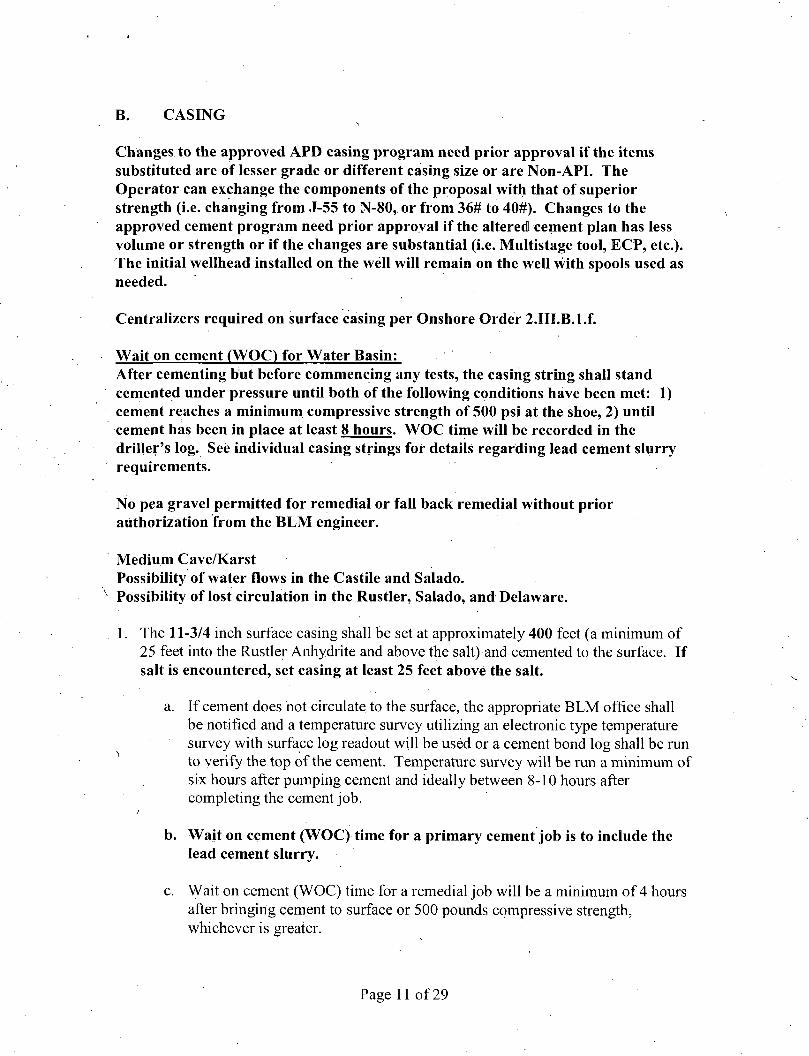
B. CASING
Changes to the approved APD casing program need prior approval if the items substituted are of lesser grade or different casing size or are Non-API. The Operator can exchange the components of the proposal with that of superior strength (i.e. changing from J-55 to N-80, or from 36# to 40#). Changes to the approved cement program need prior approval if the altered cement plan has less volume or strength or if the changes are substantial (i.e. Multistage tool, ECP, etc.). The initial wellhead installed on the well will remain on the well with spools used as needed.
Centralizers required on surface casing per Onshore Order 2.III.B.l.f.
Wait on cement (WOC) for Water Basin: After cementing but before commencing any tests, the casing string shall stand cemented under pressure until both of the following conditions have been met: 1) cement reaches a minimum compressive strength of 500 psi at the shoe, 2) until cement has been in place at least 8 hours. WOC time will be recorded in the driller's log. See individual casing strings for details regarding lead cement slurry requirements.
No pea gravel permitted for remedial or fall back remedial without prior authorization from the BLM engineer.
Medium Cave/Karst Possibility of water flows in the Castile and Salado. Possibility of lost circulation in the Rustler, Salado, and Delaware.
1. The 11-3/4 inch surface casing shall be set at approximately 400 feet (a minimum of 25 feet into the Rustler Anhydrite and above the salt) and cemented to the surface. If salt is encountered, set casing at least 25 feet above the salt.
a. If cement does not circulate to the surface, the appropriate BLM office shall be notified and a temperature survey utilizing an electronic type temperature survey with surface log readout will be used or a cement bond log shall be run to verify the top of the cement. Temperature survey will be run a minimum of six hours after pumping cement and ideally between 8-10 hours after completing the cement job.
b. Wait on cement (WOC) time for a primary cement job is to include the lead cement slurry.
c. Wait on cement (WOC) time for a remedial job will be a minimum of 4 hours after bringing cement to surface or 500 pounds compressive strength, whichever is greater.
Page 11 of29
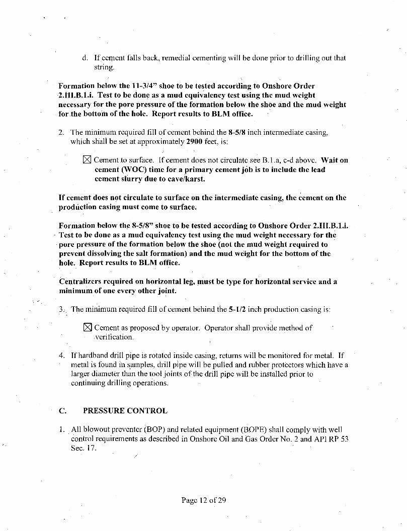
d. If cement falls back, remedial cementing will be done prior to drilling out that string.
Formation below the 11-3/4" shoe to be tested according to Onshore Order 2.III.B.1 .i. Test to be done as a mud equivalency test using the mud weight necessary for the pore pressure of the formation below the shoe and the mud weight for the bottom of the hole. Report results to BLM office.
2. The minimum required fill of cement behind the 8-5/8 inch intermediate casing, which shall be set at approximately 2900 feet, is:
^ Cement to surface. If cement does not circulate see B.l.a, c-d above. Wait on cement (WOC) time for a primary cement job is to include the lead cement slurry due to cave/karst.
If cement does not circulate to surface on the intermediate casing, the cement on the production casing must come to surface.
Formation below the 8-5/8" shoe to be tested according to Onshore Order 2.HI.B.1.L Test to be done as a mud equivalency test using the mud weight necessary for the pore pressure of the formation below the shoe (not the mud weight required to prevent dissolving the salt formation) and the mud weight for the bottom of the hole. Report results to BLM office.
Centralizers required on horizontal leg, must be type for horizontal service and a minimum of one every other joint.
3.- The minimum required fi l l of cement behind the 5-1/2 inch production casing is:
^ Cement as proposed by operator. Operator shall provide method of verification.
4. If hardband drill pipe is rotated inside casing, returns will be monitored for metal. If metal is found in samples, drill pipe will be pulled and rubber protectors which have a larger diameter than the tool joints of the drill pipe will be installed prior to continuing drilling operations.
PRESSURE CONTROL
All blowout preventer (BOP) and related equipment (BOPE) shall comply with well control requirements as described in Onshore Oil and Gas Order No. 2 and API RP 53 Sec. 17. '
Page 12 of 29
2. Variance approved to use flex line from BOP to choke manifold. Check condition of flexible line from BOP to choke manifold, replace if exterior is damaged or if line fails test. Line to be as straight as possible with no hard bends and is to be anchored according to Manufacturer's requirements. The flexible hose can be exchanged with a hose of equal size and equal or greater pressure rating. Anchor requirements, specification sheet and hydrostatic pressure test certification matching the hose in service, to be onsite for review. These documents shall be posted in the
• company man's trailer and on the rig floor. If the BLM inspector questions the straightness of the hose, a BLM engineer will be contacted and will review in the field or via picture supplied by inspector to determine if changes are required (operator shall expect delays i f this occurs).
3. Operator has proposed a multi-bowl wellhead assembly.. This assembly will only be tested when installed on the surface casing. Minimum working pressure of the blowout preventer (BOP) and related equipment (BOPE) required for drilling below the surface casing shoe shall be 5000 (5M) psi.
a. Wellhead shall be installed by manufacturer's representatives, submit documentation with subsequent sundry.
b. If the welding is performed by a third party, the manufacturer's representative shall monitor the temperature to verify that it does not exceed the maximum temperature of the seal.
c. Manufacturer representative shall install the test plug for the initial BOP test.
d. Operator shall perform the intermediate casing integrity test to 70% of the casing burst. This will test the multi-bowl seals.
e. If the cement does not circulate and one inch operations would have been possible with a standard wellhead, the well head shall be cut off, cementing operations performed and another wellhead installed.
5M system requires an HCR valve, remote kill line and annular to match. The remote kill line is to be installed prior to testing the system and tested to stack pressure.
Page 13 of 29
4. The appropriate BLM office shall be notified a minimum of 4 hours in advance for a representative to witness the tests.
a. In a water basin, for all casing strings utilizing slips, these are to be set as soon as the crew and rig are ready and any fallback cement remediation has been done. The casing cut-off and BOP installation can be initiated four hours after installing the slips, which will be approximately six hours after bumping the plug. For those casing strings not using slips, the minimum wait time before cut-off is eight hours after bumping the plug. BOP/BOPE testing can begin after cut-off or once cement reaches 500 psi compressive strength (including lead when specified), whichever is greater. However, i f the float does not hold, cut-off cannot be initiated until cement reaches 500 psi compressive strength (including lead when specified).
b. The tests shall be done by an independent service company utilizing a test plug not a cup or J-packer.
c. The test shall be run on a 5000 psi chart for a 2-3M BOP/BOP, on a 10000 psi chart for a 5M BOP/BOPE and on a 15000 psi chart for a 10M BOP/BOPE. If a linear chart is used, it shall be a one hour chart. A circular chart shall have a maximum 2 hour clock. If a twelve hour or twenty-four hour chart is used, tester shall make a notation that it is run with a two hour clock.
d. The results of the test shall be reported to the appropriate BLM office.
e. All tests are required to be recorded on a calibrated test chart. A copy of the BOP/BOPE test chart and a copy of independent service company test will be submitted to the appropriate BLM office.
f. The BOP/BOPE test shall include a low pressure test from 250 to 300 psi. The test will be held for a minimum of 10 minutes if test is done with a test
, plug and 30 minutes without a test plug. This test shall be performed prior to the test at full stack pressure.
D. DRILL STEM TEST
If drill stem tests are performed, Onshore Order 2.III.D shall be followed.
Page 14 of29
E. WASTE MATERIAL AND FLUIDS
All waste (i.e. drilling fluids, trash, salts, chemicals, sewage, gray water etc.) created as a result of drilling operations and completion operations shall be safely contained and disposed of properly at a waste disposal facility. No waste material or fluid shall be disposed of on the well location or surrounding area.
Porto-johns and trash containers will be on-location during fracturing operations or any other crew-intensive operations.
CRW 070215
Page 15 of 29
VIII. PRODUCTION (POST DRILLING)
A. WELL STRUCTURES & FACILITIES
Placement of Production Facilities Production facilities should be placed on the well pad to allow for maximum interim recontouring and revegetation of the well location.
Exclosure Netting (Open-top Tanks) Immediately following active drilling or completion operations, the operator will take actions necessary to prevent wildlife and livestock access, including avian wildlife, to all open-topped tanks that contain or have the potential to contain salinity sufficient to cause harm to wildlife or livestock, hydrocarbons, or Resource Conservation and Recovery Act of 1976-exempt hazardous substances. At a minimum, the operator will net, screen, or cover open-topped tanks to exclude wildlife and livestock and prevent mortality. If the operator uses netting, the operator will cover and secure the open portion of the tank to prevent wildlife entry. The operator will net, screen, or cover the tanks until the operator removes the tanks from the location or the tanks no longer contain substances that could be harmful to wildlife or livestock. Use a maximum netting mesh size of 1 Vi inches. The netting must not be in contact with fluids and must not have holes or gaps.
Chemical and Fuel Secondary Containment and Exclosure Screening The operator will prevent all hazardous, poisonous, flammable, and toxic substances from coming into contact with soil and water. At a minimum, the operator will install and maintain an impervious secondary containment system for any tank or barrel containing hazardous, poisonous, flammable, or toxic substances sufficient to contain the contents of the tank or barrel and any drips, leaks, and anticipated precipitation. The operator will dispose of fluids within the containment system that do not meet applicable state or U. S. Environmental Protection Agency livestock water standards in accordance with state law; the operator must not drain the fluids to the soil or ground. The operator will design, construct, and maintain all secondary containment systems to prevent wildlife and livestock exposure to harmful substances. At a minimum, the operator will install effective wildlife and livestock exclosure systems such as fencing, netting, expanded metal mesh, lids, and grate covers. Use a maximum netting mesh size of 1 Vi inches. '
Open-Vent Exhaust Stack Exclosures The operator will construct, modify, equip, and maintain all open-vent exhaust stacks on production equipment to prevent birds and bats from entering, and to discourage perching, roosting, and nesting. {Recommended exclosure structures on open-vent exhaust stacks are in the shape of a cone.) Production equipment includes, but may not be limited to, tanks, heater-treaters, separators, dehydrators, flare stacks, in-line units, and compressor mufflers.
Containment Structures Proposed production facilities such as storage tanks and other vessels will have a secondary containment structure that is constructed to hold the capacity of 1.5 times the
Page 16 of 29
largest tank, plus freeboard to account for precipitation, unless more stringent protective requirements are deemed necessary.
Painting Requirement All above-ground structures including meter housing that are not subject to safety requirements shall be painted a flat non-reflective paint color, Shale Green from the BLM Standard Environmental Color Chart (CC-001: June 2008).
B. PIPELINES STANDARD STIPULATIONS FOR SURFACE INSTALLED PIPELINES
A copy of the application (Grant, Sundry Notice, APD) and attachments, including stipulations, survey plat and/or map, will be on location during construction. BLM personnel may request to you a copy of your permit during construction to ensure compliance with all stipulations.
Holder agrees to comply with the following stipulations to the satisfaction of the Authorized Officer:
1. The holder shall indemnify the United States against any liability for damage to life or property arising from the occupancy or use of public lands under this grant.
2. The holder shall comply with all applicable Federal laws and regulations existing or hereafter enacted or promulgated. In any event, the holder shall comply with the Toxic Substances Control Act of 1976 as amended, 15 USC 2601 et seg. (1982) with regards to any toxic substances that are used, generated by or stored on the right-of-way or on facilities authorized under this right-of-way grant. (See 40 CFR, Part 702-799 and especially, provisions on polychlorinated biphenyls, 40 CFR 761.1-761.193.) Additionally, any release of toxic substances (leaks, spills, etc.) in excess of the reportable quantity established by 40 CFR, Part 117 shall be reported as required by the Comprehensive Environmental Response, Compensation, and'Liability Act, section 102b. A copy of any report required or requested by any Federal agency or State government as a result of a reportable release or spill of any toxic substances shall be furnished to the authorized officer concurrent with the filing of the reports to the involved Federal agency or State government.
3. The holder agrees to indemnify the United States against any liability arising from the release of any hazardous substance or hazardous waste (as these terms are defined in the Comprehensive Environmental Response, Compensation'and Liability Act of 1980, 42 U.S.C. 9601, et seq. or the Resource Conservation and Recovery Act, 42 U.S.C. 6901, et seq.) on the Right-of-Way (unless the release or threatened release is wholly unrelated to activity of the Right-of-Way holder's activity on the Right-of-Way), or resulting from the activity of the Right-of-Way holder on the Right-of-Way. This agreement applies without regard to whether a release is caused by the holder, its agent, or unrelated third parties.
Page 17 of 29
4. The holder shall be liable for damage or injury to the United States to the extent provided by 43 CFR Sec. 2883.1-4. The holder shall be held to a standard of strict liability for damage or injury to the United States resulting from pipe rupture, fire, or spills caused or substantially aggravated by any of the following within the right-of-way or permit area:
a. Activities of the holder including, but not limited to construction, operation, maintenance, and termination of the facility.
b. Activities of other parties including, but not limited to: (1) Land clearing. (2) Earth-disturbing and earth-moving work. (3) Blasting. (4) Vandalism and sabotage.
c. Acts of God.
The maximum limitation for such strict liability damages shall not exceed one million dollars ($1,000,000) for any one event, and any liability in excess of such amount shall be determined by the ordinary rules of negligence of the jurisdiction in which the damage or injury occurred.
This section shall not impose strict liability for damage or injury resulting primarily from an act of war or from the negligent acts or omissions of the United States.
5. If, during any phase of the construction, operation, maintenance, or termination of the pipeline, any oil, salt water, or other pollutant should be discharged from the pipeline system, impacting Federal lands, the control and total removal, disposal, and cleaning up of such oil, salt water, or other pollutant, wherever found, shall be the responsibility of the holder, regardless of fault. Upon failure of the holder to control, dispose of, or clean up such discharge on or affecting Federal lands, OP to repair all damages resulting therefrom, on the Federal lands,, the Authorized Officer may take such measures as he deems necessary to control and clean up the discharge and restore the area, including, where appropriate, the aquatic environment and fish and wildlife habitats, at the full expense of the holder. Such action.by the Authorized Officer shall not relieve the holder of any responsibility as provided herein.
6. All construction and maintenance activity will be confined to the authorized right-of-way width of 20 feet. If the pipeline route follows an existing road or buried pipeline right-of-way, the surface pipeline must be installed no farther than 10 feet from the edge of the road or buried pipeline right-of-way. If existing surface pipelines prevent this distance, the proposed surface pipeline must be installed immediately adjacent to the outer surface pipeline. All construction and maintenance activity will be confined to existing roads or right-of-ways.
7. No blading or clearing of any vegetation will be allowed unless approved in writing by the Authorized Officer.
Page 18 of 29
8. The holder shall install the pipeline on the surface in such a manner that will minimize suspension of the pipeline across low areas in the terrain. In hummocky of duney areas, the pipeline will be "snaked" around hummocks and dunes rather then suspended across these features.
9. The pipeline shall be buried with a minimum of 24 inches under all roads, "two-tracks," and trails. Burial of the pipe will continue for 20 feet on each side of each crossing. The condition of the road, upon completion of construction, shall be returned to at least its former state with no bumps or dips remaining in the road surface.
10. The holder shall minimize disturbance to existing fences and other improvements on public lands. The holder is required to promptly repair improvements to at least their former state. Functional use of these improvements will be maintained at all times. The holder will contact the owner of any improvements prior to disturbing them. When necessary to pass through a fence line, the fence shall be braced on both sides of the passageway prior to cutting of the fence. No permanent gates will be allowed unless approved by the Authorized Officer.
11. In those areas where erosion control structures are required to stabilize soil conditions, the holder will install such structures as are suitable for the specific soil conditions being encountered and which are in accordance with sound resource management practices.
12. Excluding the pipe, all above-ground structures not subject to safety requirement shall be painted by the holder to blend with the natural color of the landscape. The paint used shall be a color which simulates "Standard Environmental Colors" - Shale Green, Munsell Soil Color No. 5Y 4/2; designated by the Rocky Mountain Five State Interagency Committee.
13. The pipeline will be identified by signs at the point of origin and completion of the right-of-way and at all road crossings. At a minimum, signs will state the holder's name, BLM serial number, and the product being transported. Signs will be maintained in a legible condition for the life of the pipeline.
14. The holder shall not use the pipeline route as a road for purposes other than routine maintenance as determined necessary by the Authorized Officer in consultation with the. holder. The holder will take whatever steps are necessary to ensure that the pipeline route is not used as a roadway.
15. Any cultural and/or paleontological resource (historic or prehistoric site or object) discovered by the holder, or any person working on his behalf, on public or Federal land shall be immediately reported to the authorized officer. Holder shall suspend all operations in the immediate area of such discovery until written authorization to proceed is issued by the authorized officer. An evaluation of the discovery will be made by the authorized officer to determine appropriate cultural or scientific values. The holder will be responsible for the cost of evaluation and any decision as to proper mitigation
Page 19 of29
measures will be made by the authorized officer after consulting with the holder.
16. The operator shall be held responsible i f noxious weeds become established within the areas of operations. Weed control shall be required on the disturbed land where noxious weeds exist, which includes the roads, powerline corridor, and adjacent land affected by the establishment of weeds due to this action. The operator shall consult with the Authorized Officer for acceptable weed control methods, which include following EPA and BLM requirements and policies.
17. Surface pipelines must be less than or equal to 4 inches and a working pressure below 125 psi.
BURIED PIPELINE STIPULATIONS
A copy of the application (Grant, APD, or Sundry Notice) and attachments, including conditions of approval, survey plat and/or map, will be on location during construction. BLM personnel may request to you a copy of your permit during construction to ensure compliance with all stipulations.
Holder agrees to comply with the following stipulations to the satisfaction of the Authorized Officer:
1. The Holder shall indemnify the United States against any liability for damage to life or property arising from the occupancy or use of public lands under this grant.
2. The Holder shall comply with all applicable Federal laws and regulations existing or hereafter enacted or promulgated. In any event, the holder shall comply with the Toxic Substances Control Act of 1976 as amended, 15 USC 2601 et seq. (1982) with regards to any toxic substances that are used, generated by or stored on the right-of-way or on facilities authorized under this right-of-way grant. (See 40 CFR Part 702-799 and especially, provisions on polychlorinated biphenyls, 40 CFR 761.1-761.193.) Additionally, any release of toxic substances (leaks, spills, etc.) in excess of the reportable quantity established by 40 CFR Part 117 shall .be reported as required by the Comprehensive Environmental Response, Compensation, and Liability Act, section 102b. A copy of any report required or requested by any Federal agency or State government as a result, of a reportable release or spill of any toxic substances shall be furnished to the authorized officer concurrent with the filing of the reports to the involved Federal agency or State government.
3. The holder agrees to indemnify the United States against any liability arising from the release of any hazardous substance or hazardous waste (as these terms are defined in the Comprehensive Environmental Response, Compensation and Liability Act of 1980, 42 U.S.C. 9601, et seq. or the Resource Conservation and Recovery Act, 42 U.S.C.6901, et seg.) on the Right-of-Way (unless the release or threatened release is wholly unrelated to the Right-of-Way holder's activity on the Right-of-Way), or resulting from the activity of the Right-of-Way holder on the Right-of-Way. This agreement applies without regard to whether a release is caused by the holder, its agent, or unrelated third parties.
4. If, during any phase of the construction, operation, maintenance, or termination of the pipeline, any oil or other pollutant should be discharged from the pipeline system, impacting Federal lands, the control and total removal, disposal, and cleaning up of such oil or other
Page 20 of 29
pollutant, wherever found, shall be the responsibility of holder, regardless of fault. Upon failure of holder to control, dispose of, or clean up such discharge on or affecting Federal lands, or to repair all damages resulting therefrom, on the Federal lands, the Authorized Officer may take such measures as he deems necessary to control and clean up the discharge and restore the area, including where appropriate, the aquatic environment and fish and wildlife habitats, at the full expense'of the holder. Such action by the Authorized Officer shall not relieve holder of any responsibility as provided herein. 5. All construction and maintenance activity will be confined to the authorized right-of-way.
6. The pipeline will be buried with a minimum cover of 36 inches between the top of the pipe and ground level.
7. The maximum allowable disturbance for construction in this right-of-way will be 30 feet:
• Blading of vegetation within the right-of-way will be allowed: maximum width of blading operations will not exceed 20 feet. The trench is included in this area. {Blading is defined as the complete removal of brush and ground vegetation)
• Clearing of brush species within the right-of-way will be allowed: maximum width of
clearing operations will not exceed 30 feet. The trench and bladed area are included in this area. {Clearing is defined as the removal of brush while leaving ground vegetation (grasses, weeds, etc.) intact. Clearing is best accomplished by holding the blade 4 to 6 inches above the ground surface.)
• The remaining area of the right-of-way (if any) shall only be disturbed by compressing the vegetation. {Compressing can be caused by vehicle tires, placement of equipment, etc.)
8. The holder shall stockpile an adequate amount of topsoil where blading is allowed. The topsoil to be stripped is approximately 6 inches in depth. The topsoil will be segregated from other spoil piles from trench construction. The topsoil will be evenly distributed over the bladed area for the preparation of seeding.
9. The holder shall minimize disturbance to existing fences and other improvements on public lands. The holder is required to promptly repair improvements to at least their former state. Functional use of these improvements will be maintained at all times. The holder will contact the owner of any improvements prior to disturbing them. When necessary to pass through a fence line, the fence shall be braced on both sides of the passageway prior to cutting of the fence. No permanent gates will be allowed unless approved by the Authorized Officer.
10. Vegetation, soil, and rocks left as a result of construction or maintenance activity will be randomly scattered on this right-of-way and will not be left in rows, piles, or berms, unless otherwise approved by the Authorized Officer. The entire right-of-way shall be recontoured to match the surrounding landscape. The backfilled soil shall be compacted and a 6 inch berm will be left over the ditch line to allow for settling back to grade.
11. In those areas where erosion control structures are required to stabilize soil conditions, the holder will install such structures as are suitable for the specific soil conditions being encountered and which are in accordance with sound resource management practices.
Page 21 of29
12. The holder will reseed all disturbed areas. Seeding will be done according to the attached seeding requirements, using the following seed mix.
( ) seed mixture 1 ( X) seed mixture 2 ( ) seed mixture 2/LPC
( ) seed mixture 3 ( ) seed mixture 4 ( ) Aplomado Falcon Mixture
13. All above-ground structures not subject to safety requirements shall be painted by the holder to blend with the natural color of the landscape. The paint used shall be color which simulates "Standard Environmental Colors" - Shale Green, Munsell Soil Color No. 5Y 4/2.
14. The pipeline will be identified by signs at the point of origin and completion of the right-of-way and at all road crossings. At a minimum, signs will state the holder's name, BLM serial number, and the product being transported. All signs and information thereon will be posted in a permanent, conspicuous manner, and will be maintained in a legible condition for the life of the pipeline.
15. The holder shall not use the pipeline route as a road for purposes other than routine maintenance as determined necessary by the Authorized Officer in consultation with the holder before maintenance begins. The holder will take whatever steps are necessary to ensure that the pipeline route is not used as a roadway. As determined necessary during the life of the pipeline, the Authorized Officer may ask the holder to construct temporary deterrence structures.
16. Any cultural and/or paleontological resources (historic or prehistoric site or object) discovered by the holder, or any person working on his behalf, on public or Federal land shall be immediately reported to the Authorized Officer. Holder shall suspend all operations in the immediate area of such discovery until written authorization to proceed is issued by the Authorized Officer. An evaluation of the discovery will be made by the Authorized Officer to determine appropriate actions to prevent the loss of significant cultural or scientific values. The holder will be responsible for the cost of evaluation and any decision as to proper mitigation measures will be made by the Authorized Officer after consulting with the holder.
17. The operator shall be held responsible if noxious weeds become established within the areas of operations. Weed control shall be required on the disturbed land where noxious weeds exist, which includes associated roads, pipeline corridor and adjacent land affected by the establishment of weeds due to this action. The operator shall consult with the Authorized Officer for acceptable weed control methods, which include following EPA and BLM requirements and policies.
18. Escape Ramps - The operator will construct and maintain pipeline/utility trenches that are not otherwise fenced, screened, or netted to prevent livestock, wildlife, and humans' from becoming entrapped. At a minimum, the operator will construct and maintain escape ramps, ladders, or other methods of avian and terrestrial wildlife escape in the trenches according to the following criteria:
a. Any trench left open for eight (8) hours or less is not required to have escape ramps; however, before the trench is backfilled, the contractor/operator shall inspect the trench for wildlife, remove all trapped wildlife, and release them at least 100 yards from the trench.
b. For trenches left open for eight (8) hours or more, earthen escape ramps (built at no more than a 30 degree slope and spaced no more than 500 feet apart) shall be placed in the trench.
Page 22 of 29
C. Electric Line STIPULATIONS FOR BURIED ELECTRIC DISTRIBUTION LINES
The holder agrees to comply with the following stipulations to the satisfaction of the Authorized Officer, BLM.
1. The Holder shall indemnify the United States against any liability for damage to life or property arising from the occupancy or use of public lands under this authorization.
2. The Holder shall comply with all applicable Federal laws and regulations existing or hereafter enacted or promulgated. In any event, the Holder shall comply with the Toxic Substances Control Act of 1976, as amended (15 U.S.C. 2601, et. seq.) with regard to any toxic substances that are used, generated by or stored on the powerline route or on facilities authorized. (See 40 CFR, Part 702-799 and especially, provisions on polychlorinated biphenyls, 40 CFR 761.1-761.193.) Additionally, any release of toxic substances (leaks, spills, etc.) in excess of the reportable quantity established by 40 CFR, Part 117 shall be reported as required by the Comprehensive Environmental Response, Compensation and Liability Act, Section 102b. A copy of any report required or requested by any Federal agency or State government as a result of a reportable release or spill of any toxic substances shall be furnished to the Authorized Officer concurrent with the filing of the reports to the involved Federal agency or State government.
3. The Holder agrees to indemnify the United States against-any liability arising from the release of any hazardous substance or hazardous waste (as these terms are defined in the Comprehensive Environmental Response, Compensation and Liability Act of 1980, 42' U.S.C. 9601, et. seq. or the Resource Conservation and Recovery Act, 42 U.S.C. 6901, et. seq.) on the right-of-way (unless the release or threatened release is wholly unrelated to the right-of-way Holder's activity on the pipeline). This agreement applies without regard to whether a release is caused by the Holder, its agent, or unrelated third parties.
4. If, during any phase of the construction, operation, maintenance, or termination of the pipeline, any oil or other pollutant should be discharged, impacting Federal lands, the control and total removal, disposal, and cleaning up of such oil or other pollutant, wherever found, shall be the responsibility of the Holder, regardless of fault. Upon failure of the holder to control, dispose of, or clean up such discharge on or affecting Federal lands, or to repair all damages to Federal
u lands resulting therefrom, the Authorized Officer may take such measures as deemed necessary to control and cleanup the discharge and restore the area, including, where appropriate, the aquatic environment and fish and wildlife habitats, at the full expense of the Holder. Such action by the Authorized Officer shall not relieve the Holder of any liability or responsibility.
5. Any cultural and/or paleontological resource (historic or prehistoric site or object) discovered by the Holder, or any person working on the Holder's behalf, on public or Federal land shall be immediately reported to the Authorized Officer. The Holder shall suspend all operations in the immediate area of such discovery until written authorization to proceed is issued by the Authorized Officer. An evaluation of the discovery will be made by the Authorized Officer to determine appropriate actions to prevent the loss of significant cultural or scientific values. The Holder will be responsible for the cost of evaluation and any decision as to the proper mitigation measures will be made by the Authorized Officer after consulting with the holder.
6. The holder is hereby obligated to comply with procedures established in the Native American Graves Protection and Repatriation Act (NAGPRA) to protect such cultural items as human
Page 23 of 29
remains, associated funerary objects, sacred objects, and objects of cultural patrimony discovered inadvertently during the course of project implementation. In the event that any of the cultural items listed above are discovered during the course of project work, the proponent shall immediately halt the disturbance and contact the BLM within 24 hours for instructions. The proponent or initiator of any project shall be held responsible for protecting, evaluating, reporting, excavating, treating, and disposing of these cultural items according to the procedures established by the BLM in consultation with Indian Tribes."
7. The holder shall be held responsible if noxious weeds become established within the area. Evaluation of growth of the noxious weeds shall be made upon.discovery. Weed control will be required on the disturbed lands resulting from this actions, which include the roads, pads and associated pipelines and on adjacent lands affected by the establishment of weeds due to this action.
The holder shall insure that the equipment and or vehicles that will be used to construct, maintain and administer the access roads, well pad, and resulting well are not polluted with invasive and noxious weed seeds. Transporting of invasive and noxious weed seeds could occur i f the equipment and vehicles were previously used in noxious weed infested areas. In order to prevent the spread of noxious weeds, the Authorized Officer shall require that the equipment and vehicles be cleaned with either high pressure water or air prior to construction, maintenance and administration of the access roads, well pad, and resulting well.
The holder is responsible for consultation with the authorized officer and/or local authorities for acceptable weed control methods, which include following EPA and BLM requirements and policy.
8. The holder shall be responsible for maintaining the site in a sanitary condition at all times; waste materials shall be disposed of promptly at an appropriate waste disposal site. "Waste" means all discarded matter including, but not limited to human waste, trash, garbage, refuse, oil drums, petroleum products, ashes and equipment.
9. The holder shall conduct all activities associated with the construction, operation and termination of the powerline within the authorized limits.
10. No blading or clearing of any vegetation will be allowed unless approved in writing by the Authorized Officer. . .
11. The holder shall minimize disturbance to existing fences and other improvements on public lands. The holder is required to promptly repair impacted improvements to at least their former state. The holder shall contact the owner of any improvements prior to disturbing them. When necessary to pass through a fence line, the fence will be braced on both sides of the passageway prior to cutting of the fence. No permanent gates will be allowed unless approved by the Authorized Officer.
12. Construction trenches left open over night shall be covered. Covers shall be secured in place and shall be strong enough to prevent livestock or wildlife from falling through and into a hole.
13. The holder shall evenly spread the excess soil excavated from trench in the immediate vicinity of the trench structure.
14. The BLM serial number assigned to this right-of-way grant shall be posted in a permanent,
Page 24 of 29
conspicuous manner, and be maintained in a legible condition for the term of the right-of-way at all major road crossings and at all serviced facilities. Numbers will be at least two inches high and will be affixed to the pole nearest the road crossing and at the facilities served.
15. Upon cancellation, relinquishment, or expiration of this grant, the holder shall comply with those abandonment procedures as prescribed by the Authorized Officer.
16. All surface structures (poles, lines, transformers, etc.) shall be removed within 180 days of abandonment, relinquishment, or termination of use of the serviced facilities or within 180 days of abandonment, relinquishment, or termination of this grant, whichever comes first. This will not apply where the power line extends to serve an active, adjoining facility or facilities.
17. Escape Ramps - The operator, will construct and maintain pipeline/utility trenches that are not otherwise fenced, screened, or netted to prevent livestock, wildlife, and humans from becoming entrapped. At a minimum, the operator will construct and maintain escape ramps, ladders, or other methods of avian and terrestrial wildlife escape in the trenches according to the following criteria:
a. Any trench left open for eight (8) hours or less is not required to have escape ramps; however, before the trench is backfilled, the contractor/operator shall inspect the trench for wildlife, remove all trapped wildlife, and release them at least 100 yards from the trench.
b. For trenches left open for eight (8) hours or more, earthen escape ramps (built at no more than a 30 degree slope and spaced no more than 500 feet apart) shall be placed in the trench.
18. The construction of this project will consist of digging a trench to a depth of at least 40 inches. Then installing the power line and covering with backfill dirt. After completing construction of the buried power line, the line shall be marked with underground power line warning signs at least every 1,000 feet.
STANDARD STIPULATIONS FOR OVERHEAD ELECTRIC DISTRIBUTION LINES
A copy of the grant and attachments, including stipulations, survey plat and/or map, will be on location during construction. BLM personnel may request to you a copy of your permit during construction to ensure compliance with all stipulations. '
Holder agrees to comply with the following stipulations to the satisfaction of the Authorized Officer:
1. The holder shall indemnify the United States against any liability for damage to life or property arising from the occupancy or use of public lands under this grant.
2. The holder shall comply with all applicable Federal laws and regulations existing or hereafter enacted or promulgated. In any event, the holder shall comply with the Toxic Substances Control Act of 1976 as amended, 15'USC 2601 et seq. (1982) with regards to any toxic substances that are used, generated by or stored on the right-of-way or on facilities authorized under this right-of-way grant. (See 40 CFR, Part 702-799 and especially, provisions on polychlorinated biphenyls, 40 CFR 761.1-761.193.) Additionally, any release of toxic substances (leaks, spills, etc.) in excess of the reportable quantity established by 40 CFR, Part 117 shall be reported as required by the Comprehensive Environmental Response, Compensation, and Liability Act, section 102b. A
>
Page 25 of 29
copy of any report required or requested by any Federal agency or State government as a result of a reportable release or spill of any toxic substances shall be furnished to the authorized officer concurrent with the filing of the reports to the involved Federal agency or State government.
3. The holder agrees to indemnify the United States against any liability arising from the release of any hazardous substance or hazardous waste (as these terms are defined in the Comprehensive Environmental Response, Compensation and Liability Act of 1980, 42 U.S.C. 9601, et seq. or the Resource Conservation and Recovery Act, 42 U.S.C. 6901, et seq.) on the Right-of-Way (unless the release or threatened release is wholly unrelated to the Right-of-Way holder's activity on the Right-of-Way), or resulting from the activity of the Right-of-Way holder on the RightTof-Way. This agreement applies without regard to whether a release is caused by the holder, its agent, or unrelated third parties.
4. There will be no clearing or blading of the right-of-way unless otherwise agreed to in writing by the Authorized Officer.
5. Power lines shall be constructed and designed in accordance to standards outlined in "Suggested Practices for Avian Protection on Power lines: The State of the Art in 2006" Edison Electric Institute, APLIC, and the California Energy Commission 2006 . The holder shall assume the burden and expense of proving that pole designs not shown in the above publication deter raptor perching, roosting, and nesting. Such proof shall be provided by a raptor expert approved by the Authorized Officer. The BLM reserves the right to require modification or additions to all powerline structures placed on this right-of-way, should they be necessary to ensure the safety of large perching birds. Such modifications and/or additions shall be made by the holder without liability or expense to the United States.
Raptor deterrence will consist of but not limited to the following: triangle perch discouragers shall be placed on each side of the cross arms and a nonconductive perching deterrence shall be placed on all vertical poles that extend past the cross arms.
6. The holder shall minimize disturbance to existing fences and other improvements on public lands. The holder is required to promptly repair improvements to at least their former state. Functional use of these improvements will be maintained at all times. The holder will contact the owner of any improvements prior to disturbing them. When necessary to pass- through a fence line, the fence shall be braced on both sides of the passageway prior to cutting the fence. No permanent gates will be allowed unless approved by the Authorized Officer.
7. The BLM serial number assigned to this authorization shall be posted in a permanent, conspicuous manner where the power line crosses roads and at all serviced facilities. Numbers . will be at least two inches high and will be affixed to the pole nearest the road crossing and at the facilities served.
8. Upon cancellation, relinquishment, or expiration of this grant, the holder shall comply with those abandonment procedures as prescribed by the Authorized Officer.
9. All surface structures (poles, lines, transformers, etc.) shall be removed within 180 days of abandonment, relinquishment, or termination of use of the serviced facility or facilities or within 180 days of abandonment, relinquishment, cancellation, or expiration of this grant, whichever comes first. This will not apply where the power line extends service to an active, adjoining facility or facilities.
i
Page 26 of 29
10. Any cultural and/or paleontological resource (historic or prehistoric site or object) discovered by the holder, or any person working on his behalf, on public or Federal land shall be immediately reported to the Authorized Officer. Holder shall suspend all operations in the immediate area of such discovery until written authorization to proceed is issued by the Authorized Officer. An evaluation of the discovery will be made by the Authorized Officer to determine appropriate actions to prevent the loss of significant cultural or scientific values. The holder will be responsible for the cost of evaluation and any decision as to proper mitigation measures will be made by the Authorized Officer after consulting with the holder.
11. Special Stipulations: • For reclamation remove poles, lines, transformer, etc. and dispose of properly.
Fill in any holes from the poles removed.
IX. INTERIM RECLAMATION
During the life of the development, all disturbed areas not needed for active support of production operations should undergo interim reclamation in order to minimize the environmental impacts of development on other resources and uses.
Within six (6) months of well completion, operators should work with BLM surface management specialists (Jim Amos: 575-234-5909) to devise the best strategies to reduce the size of the location. Interim reclamation should allow for remedial well operations, as well as safe and efficient removal of oil arid gas.
During reclamation, the removal of caliche is important to increasing the success of revegetating the site. Removed caliche that is free of contaminants may be used for road repairs, fire walls or for building other roads and locations. In order to operate the well or complete workover operations, it may be necessary to drive, park and operate on restored interim vegetation within the previously disturbed area. Disturbing revegetated areas for production or workover operations will be allowed. I f there isv significant disturbance and loss of vegetation, the area wil l need to be revegetated. Communicate with the appropriate BLM office for any exceptions/exemptions i f needed.
Al l disturbed areas after they have been satisfactorily prepared need to be reseeded with the seed mixture provided below.
Upon completion of interim reclamation, the operator shall submit a Sundry Notices and Reports on Wells, Subsequent Report of Reclamation (Form 3160-5).
X. FINAL ABANDONMENT & RECLAMATION
At final abandonment, well locations, production facilities, and access roads must undergo "final" reclamation so that the character and productivity of the land are restored.
Page 27 of 29
Earthwork for final reclamation must be completed within six (6) months of well plugging. All pads,-pits, facility locations and roads must be reclaimed to a satisfactory revegetated, safe, and stable condition, unless an agreement is made with the landowner or BLM to keep the road and/or pad intact.
After all disturbed areas have been satisfactorily prepared, these areas need to be revegetated with the seed mixture provided below. Seeding should be accomplished by drilling on the contour whenever practical or by other approved methods. Seeding may need to be repeated until revegetation is successful, as determined by the BLM.
Operators shall contact a BLM surface protection specialist prior to surface abandonment operations for site specific objectives (Jim Amos: 575-234-5909).
Ground-level Abandoned Well Marker to avoid raptor perching: Upon the plugging and subsequent abandonment of the well, the well marker will be installed at ground level on a plate containing the pertinent information for the plugged well.
Page 28 of 29
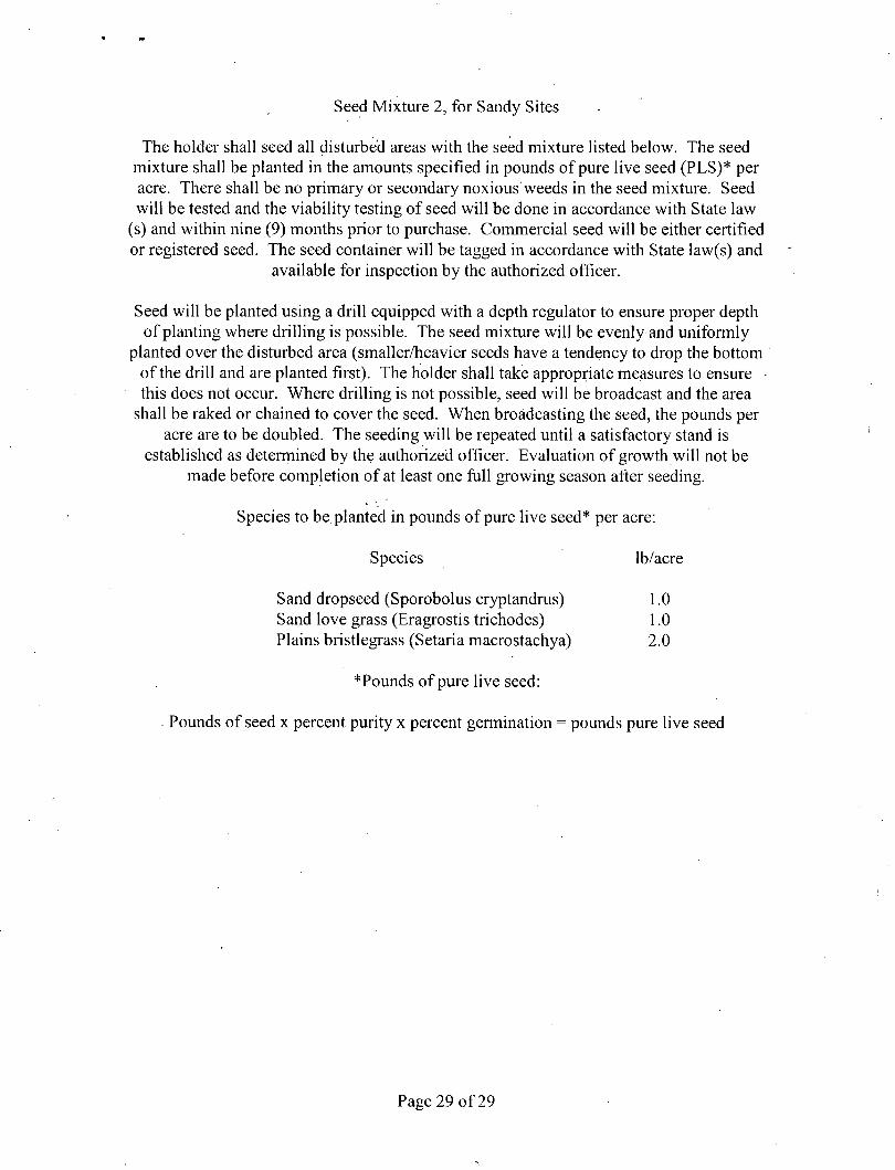
Seed Mixture 2, for Sandy Sites
The holder shall seed all disturbed areas with the seed mixture listed below. The seed mixture shall be planted in the amounts specified in pounds of pure live seed (PLS)* per acre. There shall be no primary or secondary noxious weeds in the seed mixture. Seed will be tested and the viability testing of seed will be done in accordance with State law
(s) and within nine (9) months prior to purchase. Commercial seed will be either certified or registered seed. The seed container will be tagged in accordance with State law(s) and
available for inspection by the authorized officer.
Seed will be planted using a drill equipped with a depth regulator to ensure proper depth of planting where drilling is possible. The seed mixture will be evenly and uniformly
planted over the disturbed area (smaller/heavier seeds have a tendency to drop the bottom of the drill and are planted first). The holder shall take appropriate measures to ensure this does not occur. Where drilling is not possible, seed will be broadcast and the area
shall be raked or chained to cover the seed. When broadcasting the seed, the pounds per acre are to be doubled. The seeding will be repeated until a satisfactory stand is
established as determined by the authorized officer. Evaluation of growth will not be made before completion of at least one full growing season after seeding.
Species to be planted in pounds of pure live seed* per acre:
Species lb/acre
Sand dropseed (Sporobolus cryptandrus) 1.0 Sand love grass (Eragrostis trichodes) 1.0 Plains bristlegrass (Setaria macrostachya) 2.0
*Pounds of pure live seed:
Pounds of seed x percent purity x percent germination = pounds pure live seed
\
Page 29 of 29