Embed Size (px)
Citation preview
SSD POWER FAIL PROTECTION WHITEPAPER
Document #AN0025 – Viking SSD Power Fail Protection Whitepaper | Rev. C
Purpose of this Document This application note was prepared to help OEM system designers evaluate the performance of Viking solid state drive solutions by using the same benchmarking methodology that Viking performs in it’s SSD test facility. The SSD performance stated in the Viking SSD datasheets can be achieved by following the same Viking approach to SSD benchmarking which has been outlined in this document.
Whitepaper
Whitepaper SSD Power Fail Protection
| VIKING TECHNOLOGY – AN0025 Power Fail Protection Whitepaper | Rev C 2
Abstract
Viking SSD’s that contain MLC NAND, use special SSD firmware and data protection mechanisms to protect in-flight write cache data during power fail events, without the use of capacitive hold-up circuits, which could fail at elevated temperatures.
Whitepaper SSD Power Fail Protection
| VIKING TECHNOLOGY – AN0025 Power Fail Protection Whitepaper | Rev C 3
Table of Contents
1 SUPPORTED INDUSTRIAL SSD PART NUMBERS 4
2 POWER LOSS PROTECTION USING LINK TABLE CROSS-CHECKING 4
2.1 Link Table Status Indicators 4
2.2 Condition 1: A Power Loss during a Host Write Command 5
2.3 Condition 2: A Power Loss during SSD Housekeeping 6
3 POWER LOSS PROTECTION USING CACHE FLUSHING COMMANDS 7
3.1 SSD Flash Controller Cache 7
3.2 Cache Flushing Firmware Enhancements 9 3.2.1 SmartCacheFlush 9 3.2.2 Metadata Self-Recovery from a Power Fail Event 9 3.2.3 GuaranteedFlush 10
4 INTEGRATED HOLD-UP CIRCUIT 10
5 CONCLUSION 10
REVISION HISTORY 11
Table of Tables Table 1-1: Supported Viking SSD’s ___________________________________________________________ 4 Table 2-1: Link Table Block Status Indicator Flags _______________________________________________ 5
Table of Figures Figure 2-1: Link Table Tagging for New Data____________________________________________________ 6 Figure 2-2: Valid Data Blocks Tagged as Static __________________________________________________ 6 Figure 2-3: Data Block Merge ________________________________________________________________ 6 Figure 2-4: Invalid Data Block Merge __________________________________________________________ 7 Figure 2-5: Valid Data Block Merge ___________________________________________________________ 7 Figure 3-1: Flush Cache during a File Copy Operation ____________________________________________ 8 Figure 3-2: Data Cache vs. Metadata Cache ____________________________________________________ 9 Figure 3-3: Rebuilding Metadata Mapping Table ________________________________________________ 10
Whitepaper SSD Power Fail Protection
| VIKING TECHNOLOGY – AN0025 Power Fail Protection Whitepaper | Rev C 4
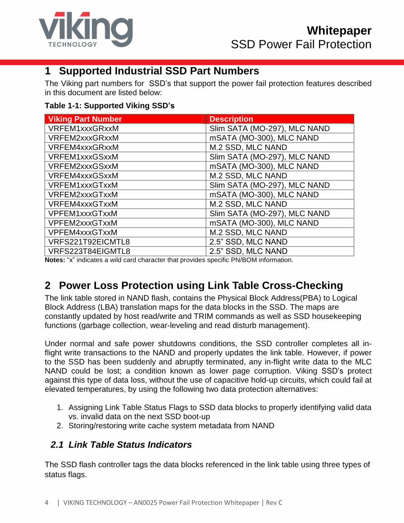
1 Supported Industrial SSD Part Numbers The Viking part numbers for SSD’s that support the power fail protection features described in this document are listed below:
Table 1-1: Supported Viking SSD’s
Viking Part Number Description
VRFEM1xxxGRxxM Slim SATA (MO-297), MLC NAND
VRFEM2xxxGRxxM mSATA (MO-300), MLC NAND
VRFEM4xxxGRxxM M.2 SSD, MLC NAND
VRFEM1xxxGSxxM Slim SATA (MO-297), MLC NAND
VRFEM2xxxGSxxM mSATA (MO-300), MLC NAND
VRFEM4xxxGSxxM M.2 SSD, MLC NAND
VRFEM1xxxGTxxM Slim SATA (MO-297), MLC NAND
VRFEM2xxxGTxxM mSATA (MO-300), MLC NAND
VRFEM4xxxGTxxM M.2 SSD, MLC NAND
VPFEM1xxxGTxxM Slim SATA (MO-297), MLC NAND
VPFEM2xxxGTxxM mSATA (MO-300), MLC NAND
VPFEM4xxxGTxxM M.2 SSD, MLC NAND
VRFS221T92EICMTL8 2.5” SSD, MLC NAND
VRFS223T84EIGMTL8 2.5” SSD, MLC NAND Notes: “x” indicates a wild card character that provides specific PN/BOM information.
2 Power Loss Protection using Link Table Cross-Checking The link table stored in NAND flash, contains the Physical Block Address(PBA) to Logical Block Address (LBA) translation maps for the data blocks in the SSD. The maps are constantly updated by host read/write and TRIM commands as well as SSD housekeeping functions (garbage collection, wear-leveling and read disturb management). Under normal and safe power shutdowns conditions, the SSD controller completes all in-flight write transactions to the NAND and properly updates the link table. However, if power to the SSD has been suddenly and abruptly terminated, any in-flight write data to the MLC NAND could be lost; a condition known as lower page corruption. Viking SSD’s protect against this type of data loss, without the use of capacitive hold-up circuits, which could fail at elevated temperatures, by using the following two data protection alternatives:
1. Assigning Link Table Status Flags to SSD data blocks to properly identifying valid data
vs. invalid data on the next SSD boot-up 2. Storing/restoring write cache system metadata from NAND
2.1 Link Table Status Indicators
The SSD flash controller tags the data blocks referenced in the link table using three types of
status flags.
Whitepaper SSD Power Fail Protection
| VIKING TECHNOLOGY – AN0025 Power Fail Protection Whitepaper | Rev C 5
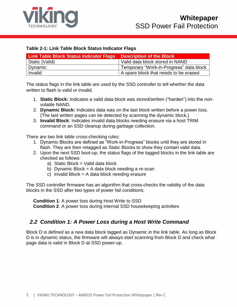
Table 2-1: Link Table Block Status Indicator Flags
Link Table Block Status Indicator Flags Description of the Block
Static (Valid) Valid data block stored in NAND
Dynamic Temporary “Work-in-Progress” data block
Invalid A spare block that needs to be erased
The status flags in the link table are used by the SSD controller to tell whether the data
written to flash is valid or invalid.
1. Static Block: Indicates a valid data block was stored/written (“harden”) into the non-volatile NAND.
2. Dynamic Block: Indicates data was on the last block written before a power loss. (The last written pages can be detected by scanning the dynamic block.)
3. Invalid Block: Indicates invalid data blocks needing erasure via a host TRIM command or an SSD cleanup during garbage collection.
There are two link table cross-checking rules:
1. Dynamic Blocks are defined as “Work-in-Progress” blocks until they are stored in flash. They are then retagged as Static Blocks to show they contain valid data.
2. Upon the next SSD boot-up, the status flags of the tagged blocks in the link table are checked as follows:
a) Static Block = Valid data block b) Dynamic Block = A data block needing a re-scan c) Invalid Block = A data block needing erasure
The SSD controller firmware has an algorithm that cross-checks the validity of the data blocks in the SSD after two types of power fail conditions:
Condition 1: A power loss during Host Write to SSD Condition 2: A power loss during internal SSD housekeeping activities
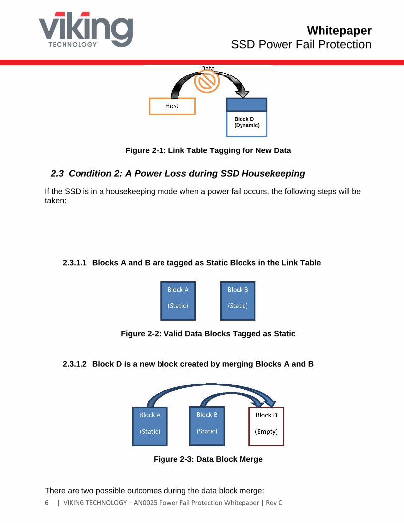
2.2 Condition 1: A Power Loss during a Host Write Command
Block D is defined as a new data block tagged as Dynamic in the link table. As long as Block D is in dynamic status, the firmware will always start scanning from Block D and check what page data is valid in Block D at SSD power-up.
Whitepaper SSD Power Fail Protection
| VIKING TECHNOLOGY – AN0025 Power Fail Protection Whitepaper | Rev C 6
Figure 2-1: Link Table Tagging for New Data
2.3 Condition 2: A Power Loss during SSD Housekeeping
If the SSD is in a housekeeping mode when a power fail occurs, the following steps will be taken:
2.3.1.1 Blocks A and B are tagged as Static Blocks in the Link Table
Figure 2-2: Valid Data Blocks Tagged as Static
2.3.1.2 Block D is a new block created by merging Blocks A and B
Figure 2-3: Data Block Merge
There are two possible outcomes during the data block merge:
Block D (Dynamic)
Whitepaper SSD Power Fail Protection
| VIKING TECHNOLOGY – AN0025 Power Fail Protection Whitepaper | Rev C 7
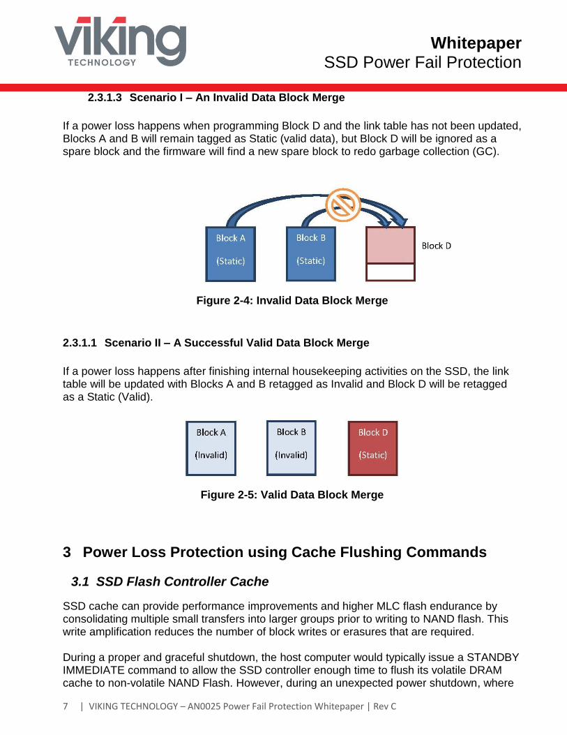
2.3.1.3 Scenario I – An Invalid Data Block Merge
If a power loss happens when programming Block D and the link table has not been updated, Blocks A and B will remain tagged as Static (valid data), but Block D will be ignored as a spare block and the firmware will find a new spare block to redo garbage collection (GC).
Figure 2-4: Invalid Data Block Merge
2.3.1.1 Scenario II – A Successful Valid Data Block Merge
If a power loss happens after finishing internal housekeeping activities on the SSD, the link table will be updated with Blocks A and B retagged as Invalid and Block D will be retagged as a Static (Valid).
Figure 2-5: Valid Data Block Merge
3 Power Loss Protection using Cache Flushing Commands
3.1 SSD Flash Controller Cache
SSD cache can provide performance improvements and higher MLC flash endurance by consolidating multiple small transfers into larger groups prior to writing to NAND flash. This write amplification reduces the number of block writes or erasures that are required. During a proper and graceful shutdown, the host computer would typically issue a STANDBY IMMEDIATE command to allow the SSD controller enough time to flush its volatile DRAM cache to non-volatile NAND Flash. However, during an unexpected power shutdown, where
Whitepaper SSD Power Fail Protection
| VIKING TECHNOLOGY – AN0025 Power Fail Protection Whitepaper | Rev C 8
power has been abruptly and unexpectedly terminated, the in-flight write cache data could become corrupted, if data protection measures are not in place. To “harden” the DRAM cache data into NAND, the host could issue an ATA command called FLUSH CACHE that would request the SSD to flush its volatile write cache into NAND. The command does not complete until the SSD controller sends an acknowledgement (ACK) back to the host indicating the cache flushing has completed. Note that the flush cache needs to be enabled by a host register setting. If the write cache is disabled by the host, maximum power fail immunity could be achieved, but SSD write performance will be reduced accordingly.
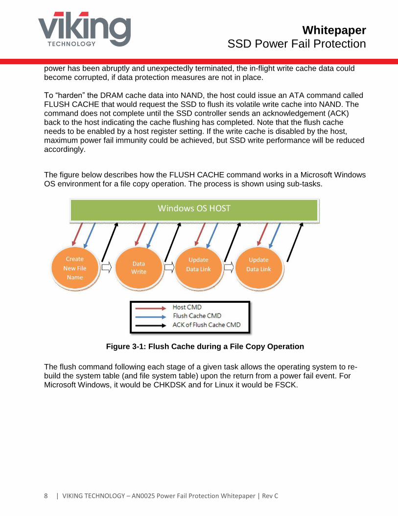
The figure below describes how the FLUSH CACHE command works in a Microsoft Windows OS environment for a file copy operation. The process is shown using sub-tasks.
Figure 3-1: Flush Cache during a File Copy Operation
The flush command following each stage of a given task allows the operating system to re-build the system table (and file system table) upon the return from a power fail event. For Microsoft Windows, it would be CHKDSK and for Linux it would be FSCK. Create
Whitepaper SSD Power Fail Protection
| VIKING TECHNOLOGY – AN0025 Power Fail Protection Whitepaper | Rev C 9
3.2 Cache Flushing Firmware Enhancements
3.2.1 SmartCacheFlush
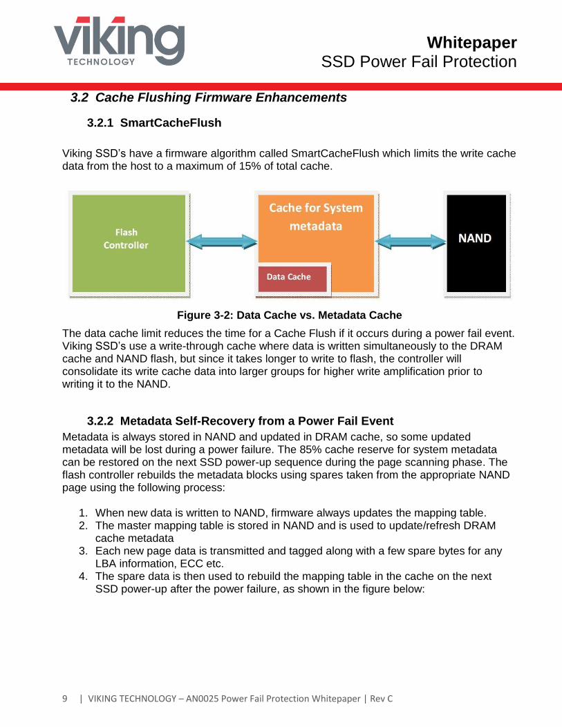
Viking SSD’s have a firmware algorithm called SmartCacheFlush which limits the write cache data from the host to a maximum of 15% of total cache.
Figure 3-2: Data Cache vs. Metadata Cache
The data cache limit reduces the time for a Cache Flush if it occurs during a power fail event. Viking SSD’s use a write-through cache where data is written simultaneously to the DRAM cache and NAND flash, but since it takes longer to write to flash, the controller will consolidate its write cache data into larger groups for higher write amplification prior to writing it to the NAND.
3.2.2 Metadata Self-Recovery from a Power Fail Event
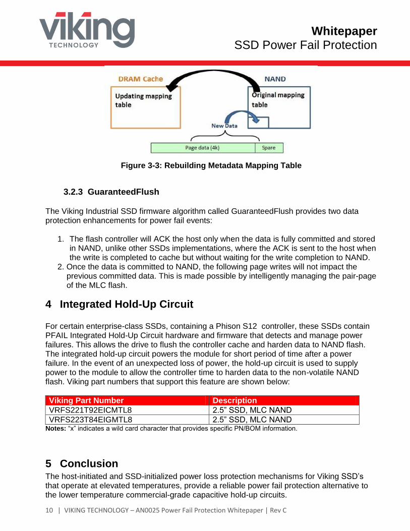
Metadata is always stored in NAND and updated in DRAM cache, so some updated metadata will be lost during a power failure. The 85% cache reserve for system metadata can be restored on the next SSD power-up sequence during the page scanning phase. The flash controller rebuilds the metadata blocks using spares taken from the appropriate NAND page using the following process:
1. When new data is written to NAND, firmware always updates the mapping table. 2. The master mapping table is stored in NAND and is used to update/refresh DRAM
cache metadata 3. Each new page data is transmitted and tagged along with a few spare bytes for any
LBA information, ECC etc. 4. The spare data is then used to rebuild the mapping table in the cache on the next
SSD power-up after the power failure, as shown in the figure below:
Whitepaper SSD Power Fail Protection
| VIKING TECHNOLOGY – AN0025 Power Fail Protection Whitepaper | Rev C 10
Figure 3-3: Rebuilding Metadata Mapping Table
3.2.3 GuaranteedFlush
The Viking Industrial SSD firmware algorithm called GuaranteedFlush provides two data protection enhancements for power fail events:
1. The flash controller will ACK the host only when the data is fully committed and stored in NAND, unlike other SSDs implementations, where the ACK is sent to the host when the write is completed to cache but without waiting for the write completion to NAND.
2. Once the data is committed to NAND, the following page writes will not impact the previous committed data. This is made possible by intelligently managing the pair-page of the MLC flash.
4 Integrated Hold-Up Circuit
For certain enterprise-class SSDs, containing a Phison S12 controller, these SSDs contain PFAIL Integrated Hold-Up Circuit hardware and firmware that detects and manage power failures. This allows the drive to flush the controller cache and harden data to NAND flash. The integrated hold-up circuit powers the module for short period of time after a power failure. In the event of an unexpected loss of power, the hold-up circuit is used to supply power to the module to allow the controller time to harden data to the non-volatile NAND flash. Viking part numbers that support this feature are shown below:
Viking Part Number Description
VRFS221T92EICMTL8 2.5” SSD, MLC NAND
VRFS223T84EIGMTL8 2.5” SSD, MLC NAND Notes: “x” indicates a wild card character that provides specific PN/BOM information.
5 Conclusion The host-initiated and SSD-initialized power loss protection mechanisms for Viking SSD’s that operate at elevated temperatures, provide a reliable power fail protection alternative to the lower temperature commercial-grade capacitive hold-up circuits.
Whitepaper SSD Power Fail Protection
| VIKING TECHNOLOGY – AN0025 Power Fail Protection Whitepaper | Rev C 11
Host initiated STANDBYIM or FLUSHCACHE commands that flush the SSD write-through-cache, combined with link table cross-checking during SSD boot-ups, mitigates the data loss risk from an unexpected power fail events. About Viking Technology Viking Technology develops and delivers innovative high-technology products that optimize the value and performance of our customers’ applications. Founded in 1989, Viking Technology has been providing Original Equipment Manufacturers (OEMs) with industry leading designs, engineering, product support and customer service for 20 years. For more information, visit http://www.vikingtechnology.com.
Revision History 2/10/15 Initial release
5/12/15 Add PN’s
9/12/17 Revise logo, address and color scheme. Add S12 PN info and holdup circuit info
Global Locations
US Headquarters Canada Office Texas Office India Office Singapore Office
2950 Red Hill Ave. Costa Mesa, CA 92626 Main: +1 714 913 2200 Fax: +1 714 913 2202
500 March Road Ottawa, ON K2K 0J9 Canada
1201 W. Crosby Road Carrollton, TX 75006 USA
A 3, Phase II, MEPZ-Special Economic Zone NH 45, Tambaram, Chennai-600045 India
No 2 Chai Chee Drive Singapore, 109840
For all of our global locations, visit our website under global locations. For sales information, email us at [email protected]


![SSD - ESOS LAB€¦ · SSD . 1 SSD Block Diagram 3.2 SSD NAND HDD . . SSD FTL . FTL NAND out-of-place update address mapping . Gabage Collection, Wear-leveling . 4. 4.1 SSD . Disksim[8]](https://img.pdfslide.net/doc/110x75/5ea6b67696cb1838a26c1ab1/ssd-esos-ssd-1-ssd-block-diagram-32-ssd-nand-hdd-ssd-ftl-ftl-nand-out-of-place.jpg)