Embed Size (px)
Citation preview

Service Training
Self-study programme 329
Volkswagen MotorhomeCalifornia 2004

2
The self-study programme shows the design and function of new developments.The contents will not be updated.
For current testing, adjustment and repair instructions, refer to the relevant service literature.
Based on the Transporter 2004, the new California fulfils the needs of both leisure and business travellers.
In this generation, the interior layout with the kitchen unit under the window and the linen cupboard at the rear left remains the same.The new California does, however, feature numerous refinements and even more comfort and flexibility.
Some highlights in the new California:
Transporter 2004 technology with diesel engines
electrohydraulic aluminium pop-up roof with a maximum load of 50 kg
very variable seat bench or bed roof bed with slatted frame variety of flexible furniture
S329_003
NEW ImportantNote
This book presents the new features in the California. For information on the technology taken from the Transporter 2004, please read:
- SSP 210 “Transporter 2004” - SSP 211 “Transporter 2004 – Electrical System”
3
Brief overview. . . . . . . . . . . . . . . . . . . . . . . . . . . . . . . . . . . . . . . . . . . . . . . . . 4
Vehicle concept . . . . . . . . . . . . . . . . . . . . . . . . . . . . . . . . . . . . . . . . . . . . . . . 8
Body. . . . . . . . . . . . . . . . . . . . . . . . . . . . . . . . . . . . . . . . . . . . . . . . . . . . . . . . . 12
Equipment . . . . . . . . . . . . . . . . . . . . . . . . . . . . . . . . . . . . . . . . . . . . . . . . . . 22
Water supply . . . . . . . . . . . . . . . . . . . . . . . . . . . . . . . . . . . . . . . . . . . . . . . . 30
Gas system . . . . . . . . . . . . . . . . . . . . . . . . . . . . . . . . . . . . . . . . . . . . . . . . . . .34
Electrical system . . . . . . . . . . . . . . . . . . . . . . . . . . . . . . . . . . . . . . . . . . . . . . .37
Heating and air conditioning. . . . . . . . . . . . . . . . . . . . . . . . . . . . . . . . . . . . .54
Contents

4
Brief overview
Proven technology
For example, the chassis with the following components has been used:
- McPherson front axle - anti-roll bars front and rear- vented disc brakes front and rear - Conti-Teves MK 25 with ABS with EDL, TCS and
EBD, ESP system with brake assist- crash-optimised pedal cluster
Further optional equipment taken from the Transporter 2004:
- sliding door and tailgate with power latching system
- anti-theft alarm with interior monitoring sensor - Park Distance Control - 3C Climatronic (with ventilation of passenger
compartment)- airbags in driver’s cab - multifunction steering wheel - radio systems
The Volkswagen California uses a large part of the technology from the Transporter 2004 Multivan with medium-height roof.
S329_050
5
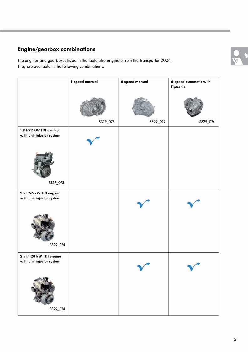
Engine/gearbox combinations
5-speed manual 6-speed manual 6-speed automatic with Tiptronic
1.9 l/77 kW TDI engine with unit injector system
2.5 l/96 kW TDI engine with unit injector system
2.5 l/128 kW TDI engine with unit injector system
The engines and gearboxes listed in the table also originate from the Transporter 2004. They are available in the following combinations.
S329_074
S329_074
S329_073
S329_075 S329_076S329_079
6
Brief overview
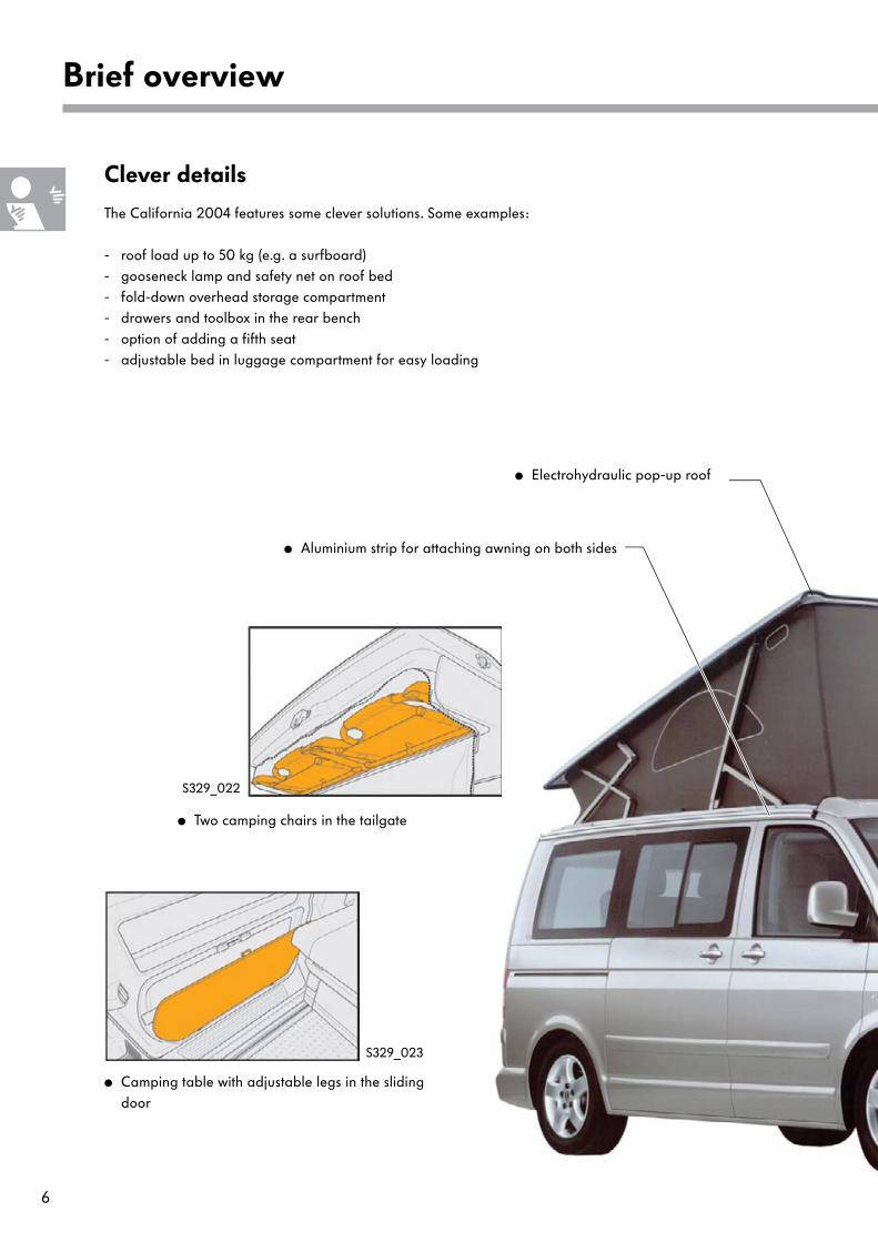
Clever details
The California 2004 features some clever solutions. Some examples:
- roof load up to 50 kg (e.g. a surfboard) - gooseneck lamp and safety net on roof bed - fold-down overhead storage compartment- drawers and toolbox in the rear bench - option of adding a fifth seat- adjustable bed in luggage compartment for easy loading
Camping table with adjustable legs in the sliding door
Two camping chairs in the tailgate
Electrohydraulic pop-up roof
Aluminium strip for attaching awning on both sides
S329_023
S329_022
7
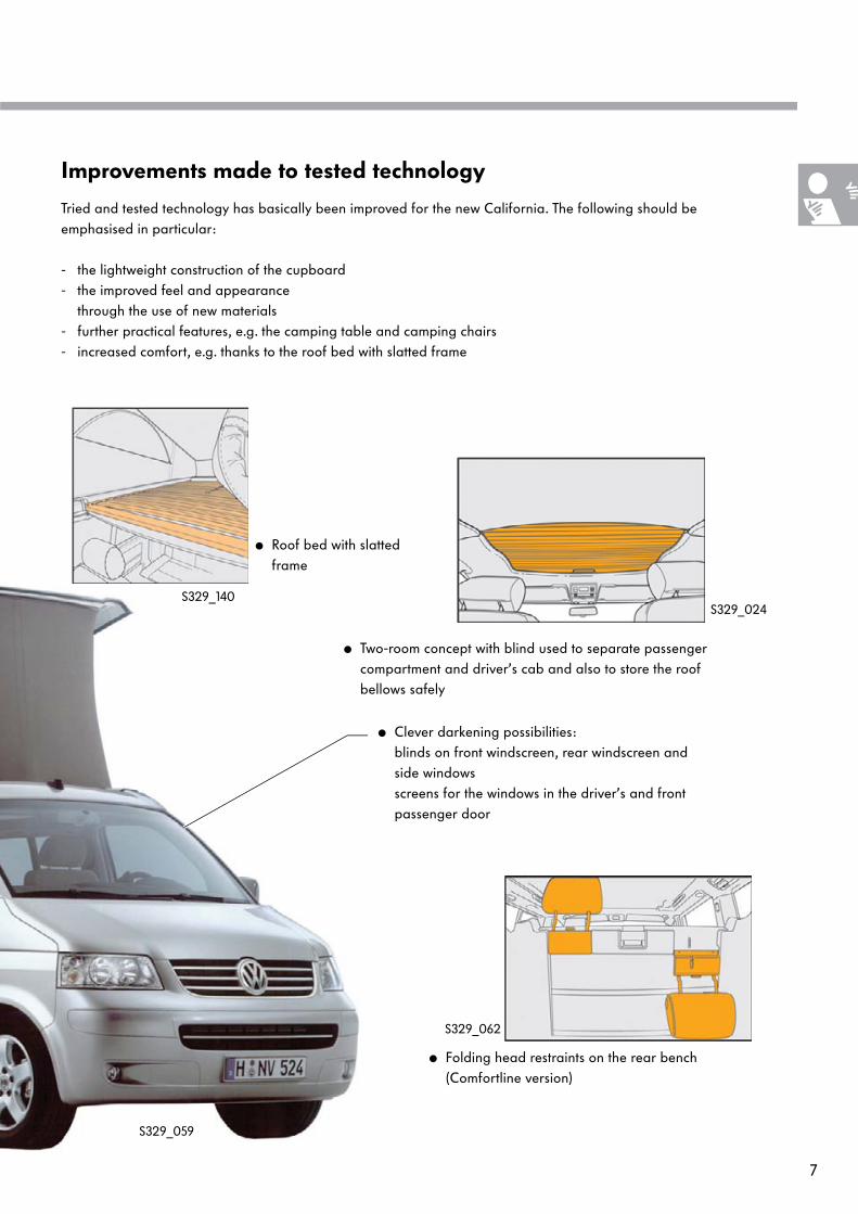
Roof bed with slatted frame
Two-room concept with blind used to separate passenger compartment and driver’s cab and also to store the roof bellows safely
Clever darkening possibilities: blinds on front windscreen, rear windscreen and side windows screens for the windows in the driver’s and front passenger door
Folding head restraints on the rear bench (Comfortline version)
Tried and tested technology has basically been improved for the new California. The following should be emphasised in particular:
- the lightweight construction of the cupboard - the improved feel and appearance
through the use of new materials - further practical features, e.g. the camping table and camping chairs- increased comfort, e.g. thanks to the roof bed with slatted frame
Improvements made to tested technology
S329_024
S329_062
S329_059
S329_140
8
Vehicle concept
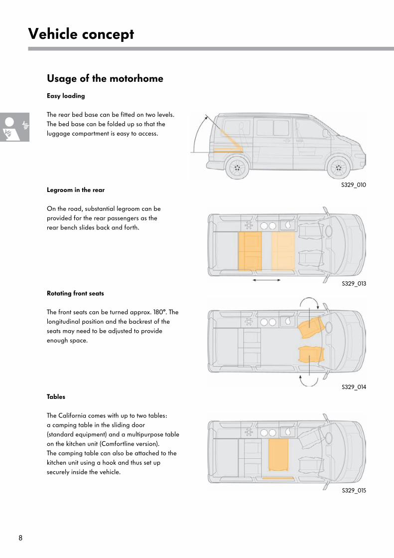
Usage of the motorhome
Legroom in the rear
Rotating front seats
Tables
Easy loading
S329_010
S329_013
S329_014
S329_015
The rear bed base can be fitted on two levels. The bed base can be folded up so that the luggage compartment is easy to access.
On the road, substantial legroom can be provided for the rear passengers as therear bench slides back and forth.
The front seats can be turned approx. 180°. The longitudinal position and the backrest of the seats may need to be adjusted to provide enough space.
The California comes with up to two tables: a camping table in the sliding door (standard equipment) and a multipurpose table on the kitchen unit (Comfortline version). The camping table can also be attached to the kitchen unit using a hook and thus set up securely inside the vehicle.

9
Camping furniture
Sleeping places in the roof
Beds in the rear
S329_016
S329_011
S329_012
The camping table in the sliding door and the two camping chairs in the tailgate can be set up quickly outdoors. The camping table has an adjustable leg to compensate uneven ground.
The roof bed sleeps two comfortably. A safety net can be fitted to prevent children falling out.
Two further beds can be set up in the rear when the rear seat backrest is folded down.

10
Vehicle concept
Technical data
S329_017
2,242
1,620
1,904
3,000
4,890
1,620
3,0
10
1,9
90
Dimensions and weights
Length 4,890 mm
Width 1,904 mm
Height 1,990 mm
Heightwith elevated roof
3,010 mm
Wheelbase 3,000 mm
Roof load 50 kg
Braked towing capacity 2,220 – 2,500 kg*
Tank capacity approx. 80 l* Depending on engine
Lower bed 200 x 114 cm
Roof bed 200 x 120 cm
Fresh water tankvolume
30l
Waste water tank volume
30l
Refrigerator box volume 42l

11
California and California Comfortline*
* The equipment may vary from country to country.
California California Comfortline
Side airbags and head airbags at front
Dual-tone horn
Auxiliary heating with timer switch and remote control
Fog lights integrated in bumper
Heated driver and front passenger seats
Sliding multi-purpose table, mounted on kitchen unit
Power latching sliding door, power latching tailgate
Bumpers and outside mirrors Not painted Painted in body colour
Stove and sink cover Aluminium Glass
Double-reflector headlights
Head restraints on the rear bench Removable Folding
Window regulator Mechanical Electrical
Outside mirrors Mechanical adjusted Electrically adjusted
All-round trim strip
Not included Included

12
Body
Body
The Transporter 2004 Multivan with medium roof forms the basis for the California. For the electrohydraulic pop-up roof, the roof is removed with the rails. Furthermore four openings have been cut into the body:
- two openings at the rear left for the fresh water supply and the 230 V exterior socket (mains connection), - one opening in the body floor for venting gas and draining the fresh water tank- another opening in the body floor for waste water drainage.
The openings are cut out at the factory in Hanover using the Plasma cutting technique.
Roof cut-out
Opening for waste water drainage in the body floor
Opening for the fresh water supply
Opening for the 230V exterior socket (mains connection)
Opening for gas vent and fresh water drainage in the body floor
S329_025
13
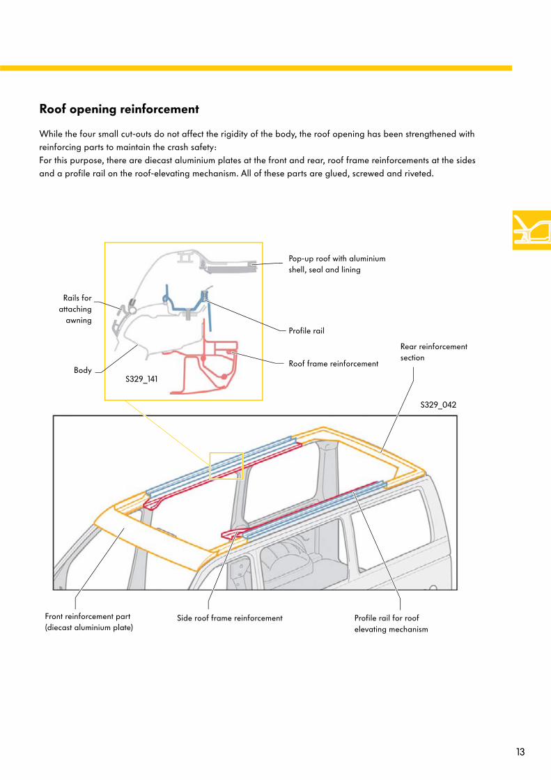
Roof opening reinforcement
While the four small cut-outs do not affect the rigidity of the body, the roof opening has been strengthened with reinforcing parts to maintain the crash safety: For this purpose, there are diecast aluminium plates at the front and rear, roof frame reinforcements at the sides and a profile rail on the roof-elevating mechanism. All of these parts are glued, screwed and riveted.
Front reinforcement part (diecast aluminium plate)
Rear reinforcement section
Profile rail for roof elevating mechanism
Side roof frame reinforcement
S329_042
S329_141
Roof frame reinforcementBody
Profile rail
Pop-up roof with aluminium shell, seal and lining
Rails forattaching
awning

14
Body
Electrohydraulic pop-up roof
The electrohydraulic pop-up roof consists of the aluminium roof shell, the roof bellows, the front props, the scissor mechanism and the following electrohydraulic components:
- roof actuation hydraulic pump V118 - roof hydraulics control unit J768- two hydraulic cylinders for the elevating mechanism each with two roof hydraulics senders G491 - G494- electrical cables and hydraulic lines
The bellows are fitted with plastic strips that ensure that they are not trapped when the electrohydraulic roof is lowered. The bellows therefore stow themselves away automatically. They are fastened along the roof cut-out and the aluminium roof shell. The bellows including the window and ventilation openings are rainproof.
The hydraulic cylinders move the front props. The force is transferred via the aluminium roof shell to the rear scissor mechanism that open and close evenly and steadily thanks to their construction.
All parts in the roof area are glued, screwed and riveted.
S329_082
Bellows Aluminium roof shell Front props
Roof actuation hydraulic pump V118
Roof hydraulics control unit J768
Hydraulic cylinder raising mechanism
Window
Scissor mechanismVentilation openingPlastic strips
Plastic strip

15
Pop-up roof electrohydraulics
The electrohydraulic pop-up roof is operated by the roof hydraulics control unit J768 that controls the roof actuation hydraulic pump V118. The roof actuation hydraulic pump is connected to two hydraulic cylinders. Each hydraulic cylinder moves the props up on both sides. Roof hydraulics senders G491 - G494 are fitted at the front and rear end stops. They indicate to the roof hydraulics control unit whether the electrohydraulic pop-up roof is completely open or closed. Two grommets seal the openings in the front reinforcement section of the roof cut-out.
The electrohydraulic pop-up roof is raised using a menu function with the rotary press knob on the operating and display unit for camping equipment E153. To lower the roof, you need to hold down the rotary press knob on the operating and display unit for camping equipment. Just after the lowering procedure is started the user will be asked whether the roof bed has been lowered, the blind opened and at least one window is open. You then press the knob again to continue the procedure.
S329_081
Roof actuation hydraulic pump V118
Grommet onfront passenger
sideGrommet on driver’s side
Roof hydraulicscontrol unit J768
Connection for operatingand display unit for camping equipment E153
Roof hydraulics sender 1 G491
Roof hydraulicssender 3 G493
Roof hydraulics sender 2 G492
Roof hydraulicssender 4 G494
Hydraulic cylinder Hydraulic cylinder

16
Body
Installing the electrohydraulics
Location of the control unit and the pump
The roof hydraulics control unit J768 as well as the roof actuation hydraulic pump V118 are mounted on the inside of the front reinforcement on the roof cut-out. The pump is embedded in a foam cushion to dampen the noise. The operating and display unit for camping equipment E153 is located in front of the hydraulic pump.
Roof actuation hydraulic pump V118
Operating and display unit for camping equipment E153
Roof hydraulicscontrol unit J768
Roof reinforcementabove frontwindscreen
S329_083
The electrohydraulic cylinders for the pop-up roof are pushed through the openings on the left and right in the front roof cut-out reinforcement and then fastened. The openings are sealed with grommets.
S329_101
S328_115
Openings for installing the electrohydraulics
Sealing grommet
Hydraulic cylinder
17
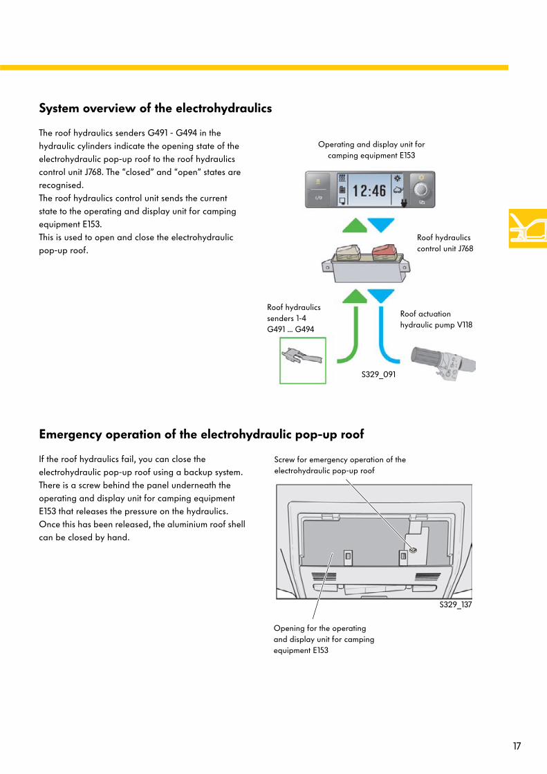
System overview of the electrohydraulics
The roof hydraulics senders G491 - G494 in the hydraulic cylinders indicate the opening state of the electrohydraulic pop-up roof to the roof hydraulics control unit J768. The “closed” and “open” states are recognised. The roof hydraulics control unit sends the current state to the operating and display unit for camping equipment E153. This is used to open and close the electrohydraulic pop-up roof.
S329_091
Operating and display unit for camping equipment E153
Roof hydraulics control unit J768
Roof actuation hydraulic pump V118
Roof hydraulics senders 1-4 G491 ... G494
Emergency operation of the electrohydraulic pop-up roof
If the roof hydraulics fail, you can close the electrohydraulic pop-up roof using a backup system. There is a screw behind the panel underneath the operating and display unit for camping equipment E153 that releases the pressure on the hydraulics. Once this has been released, the aluminium roof shell can be closed by hand.
S329_137
Screw for emergency operation of the electrohydraulic pop-up roof
Opening for the operating and display unit for camping equipment E153

18
Body
Further special features
The gas prop on the tailgate is reinforced in comparison with the Transporter basic model to compensate the increased weight of the tailgate due to the camping chairs.
Tailgate
C-rails have been mounted on the body for the roof rack and the awning rails.
Roof-rack rails can be fitted in the C-rails for the roof rack without screws. The roof-elevating mechanism also works when the roof is loaded to maximum of 50 kg.
Fastening systems
S329_056
S329_084
Special fastening adapters are used for the awning that screw into the awning rail and onto the roof frame reinforcements.
S329_100

19
Interior panels
The panels are partly taken from the Transporter 2004 Multivan basic model as well as the 1991 California.
Legend
S329_064
The sliding door panel has been redesigned to hold the camping table.
Two camping chairs are held in the tailgate panel.
All pillar lining parts have been adapted from the window up to hold and guide the blinds. The B-pillar lining has been formed from the side wall panel on the middle as the cupboard replaces the panel. Slots for blinds have been added to the right-hand B-pillar lining. The vents in the B-pillar have been omitted to allow the blinds to be fitted.
The roof lining has been omitted due to the roof bed. Instead there are roof frame panels.
The lining of the electrohydraulic pop-up roof is glued into the aluminium roof shell.

20
Body
A, B and C-pillar lining
These panels are made up of two shells: Firstly a panel is clipped to the body on the body and then screwed on. The blind is already fitted to this panel on the window side. The visible panel is clipped on top.
To reach the belt components, the visible panel needs to be removed.
Sliding door panel
The sliding door panel has been designed to hold the camping table. The lock mechanism is mounted on the sliding door behind the panel.
Opening for the button torelease the camping table
Opening for thelocking bar
on the camping table
Body
Panels on window side
Visible panel
BlindsS329_095
S329_065
21
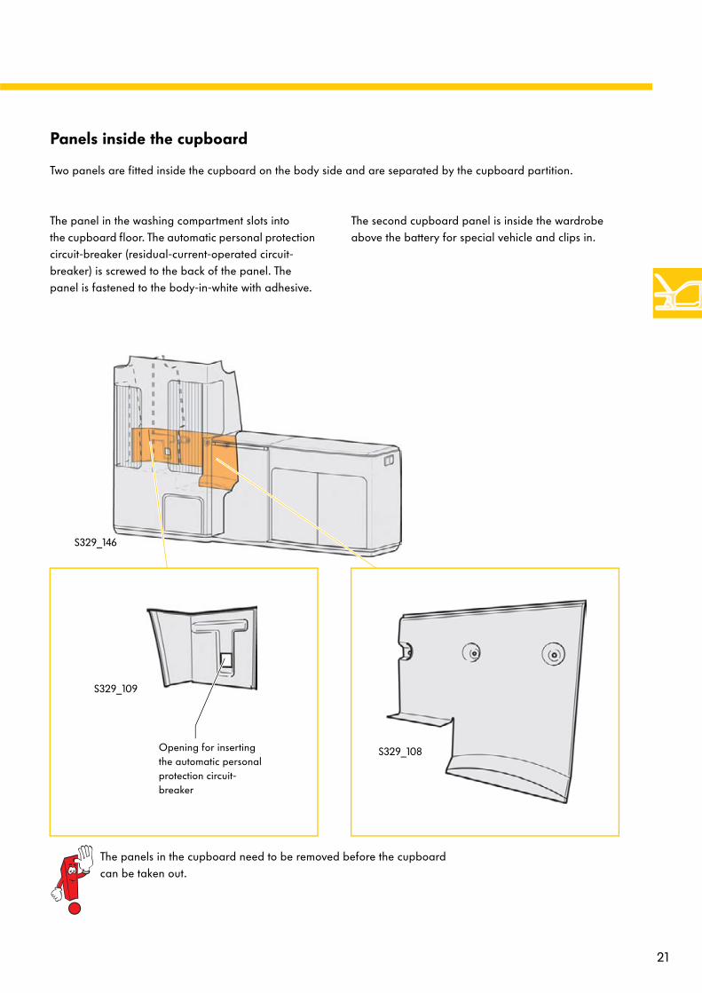
Panels inside the cupboard
Two panels are fitted inside the cupboard on the body side and are separated by the cupboard partition.
The panels in the cupboard need to be removed before the cupboard can be taken out.
S329_108
S329_109
The second cupboard panel is inside the wardrobe above the battery for special vehicle and clips in.
The panel in the washing compartment slots into the cupboard floor. The automatic personal protection circuit-breaker (residual-current-operated circuit-breaker) is screwed to the back of the panel. The panel is fastened to the body-in-white with adhesive.
Opening for inserting the automatic personal protection circuit-breaker
S329_146

22
Equipment
Storage compartments in the California
Legend:
1 Refrigerator box2 Stove, storage compartment underneath3 Sink unit, cutlery drawer and shelf underneath4 Storage compartment in driver’s door5 Storage compartment with coin holder6 Storage compartment with tank card holder7 Cup holder, ashtray and coin holder8 Bottle holder to 1.5l / rubbish bin9 Glove compartment, cooled and illuminated10 Newspaper holder
11 Storage compartment in front passenger door12 Camping table in the sliding door 13 Drawer in seat bench14 Multiple-purpose table hung on the cupboard
(Comfortline version) 15 Through-load aperture in seat bench16 Luggage compartment17 Overhead storage compartment (with loudspeakers)18 Two camping chairs in the tailgate19 Washing cupboards
The California features a wide range of storage facilities.
S329_078
The loudspeakers are inside the overhead storage compartment and are made up of a mid-range and treble speaker and a bass speaker. They are fastened inside the roof storage compartment and are covered with a plastic housing that is glued on.
Loudspeakers in overhead storage compartment
12
3
4
5-8
910
1112
1315
14
16
17
18 19
S329_135
Driver’s side loudspeaker
Storage
23
Cupboard material
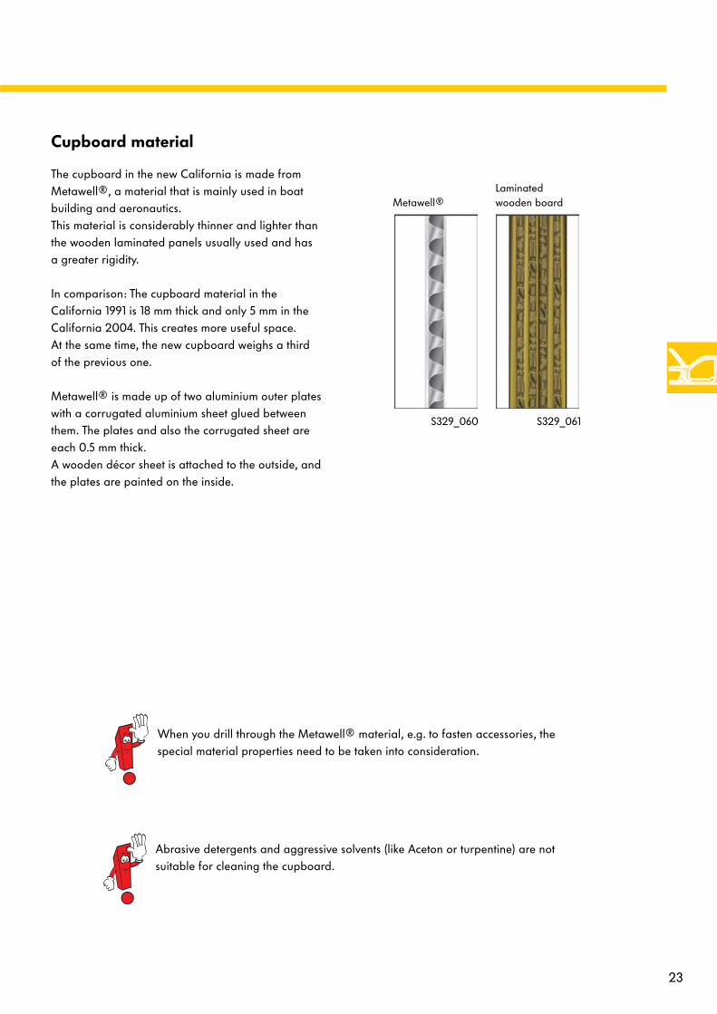
The cupboard in the new California is made from Metawell®, a material that is mainly used in boat building and aeronautics. This material is considerably thinner and lighter than the wooden laminated panels usually used and has a greater rigidity.
In comparison: The cupboard material in the California 1991 is 18 mm thick and only 5 mm in the California 2004. This creates more useful space. At the same time, the new cupboard weighs a third of the previous one.
Metawell® is made up of two aluminium outer plates with a corrugated aluminium sheet glued between them. The plates and also the corrugated sheet are each 0.5 mm thick. A wooden décor sheet is attached to the outside, and the plates are painted on the inside.
When you drill through the Metawell® material, e.g. to fasten accessories, the special material properties need to be taken into consideration.
Abrasive detergents and aggressive solvents (like Aceton or turpentine) are not suitable for cleaning the cupboard.
S329_061S329_060
Laminated wooden boardMetawell®

24
Equipment
Cupboard mounting points to the body
The cupboard is screwed to the body floor at five points. Four screws are reached from inside and one from outside.
To reach the screw from the outside, the underbody covering needs to be removed.
S329_070
Outside screw fastening point (can be reached after the underbody cover is removed)
You will find the instructions for removing the underbody panel in the latest repair guide for the Transporter 2004 Multivan.
25
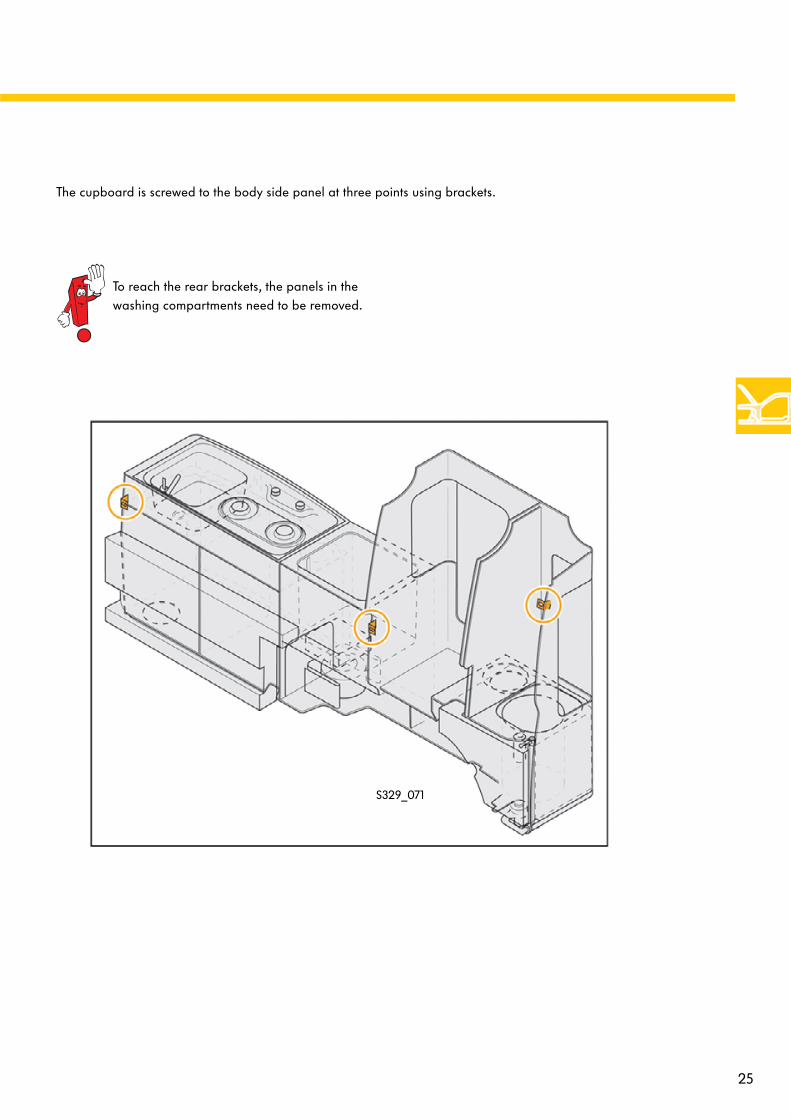
The cupboard is screwed to the body side panel at three points using brackets.
S329_071
To reach the rear brackets, the panels in thewashing compartments need to be removed.
26
Equipment
Roof bed
The roof bed is made from a slatted frame with an additional bed board and a front and rear bed support.
There is also a blind separating it from the driver’s cab to prevent the bellows hanging into the interior when the roof is folded down. The guides for the blind are underneath the slatted frame and in the front roof cut-out panel.
A safety net can be attached to prevent children or objects falling down.
The slatted frame is equipped with two gas props so it is easy to raise.
Underneath the slatted frame, there is a cover separating it from the interior.
S329_147
Gas props for the roof bed(on both sides)
Slatted frameFront roof cut-out cover with guide rails for the blind
Blind
Rear bed board (addition to slatted frame)
Roof bed cover (fastened to the slatted frame with Velcro)
Rear bed supportFront bed supportSafety net

27
Front seats
Both front seats can be turned approx. 180°.To do so, the backrests need to be set to the vertical position. The longitudinal position also needs to be adjusted. The steering column needs to be pushed in as far as possible and set as high as possible.
S329_120
S329_121
The backrest, lumbar support and armrests on the front seats in the California 2004 are adjusted mechanically.
There are rails and a bar underneath the seats for longitudinal adjustment.
Armrest lock
Wheel for backrest angle
Wheel for lumbar adjustment
Underneath each seat there is a connector for the side airbags and the bar for longitudinal adjustment. There is also an optional connector for connecting the seat heating.
Lever for releasing the lockand turning the seats
S329_139
Connector for side airbagConnector for seat heating
Bar for longitudinal adjustment
28
Equipment
Rear bench
The seat bench is anchored to the floor on the two outer rails and can be moved lengthways in 12-mm steps. It has been fitted with integrated three-point seat belts. The lock for the longitudinal adjustment of the seat bench is located underneath the seat base along with a spacious drawer with its own lock and a through-load aperture to the luggage compartment.
The drawer is connected to the bench subframe and can be removed when necessary.
The two right-hand rails can also be used to install an optional fifth seat.
Removing the bench
To remove the bench from the rails, the release lever should be held. To make this work easier, a release mechanism can be accessed on the side of the bench: You can insert a screwdriver to hold the release. You can then let go of the lever and push the bench to the furthest position forward and remove it.
S329_106
S329_105
Release Longitudinal adjustment
Drawer Through-load
aperture
Drawer release

29
The lever for adjusting the bench backrest is located in the middle of the top backrest edge. The backrest angle can be adjusted in three steps (15°, 20° and 25°) and folded down completely. If you fold over the backrest, the seat base is tilted 5° to create a level surface. The belt locks attached to steel wires are then automatically moved downwards. When the backrest is folded up, they appear again or can easily be pulled out.
The backrest has a gas prop on the side next to the cupboard to make it easier to move.
S329_107
A toolbox is attached to the back of the seat bench. It contains the standard tool set and has space for the removable tow bar (optional equipment).
In the Comfortline version, the head restraints can be folded down. The head restraints lock into the usage position. When folded down, the head restraints lock automatically due to the spring tension.
On the driver’s side of the bench, two holes have been provided near to the through-load aperture to secure a tyre repair kit (Tirefit).
Lever for folding the backrestFolding head restraint(Comfortline version)
Load-through
aperturecover
Holes for fastening atyre repair set (Tirefit)
Backrest pivotpoint
Gas prop for foldingthe backrest
Folding head restraint (Comfortline version)
Toolbox
Bottom end ofgas prop

30
Water supply
Fresh water system
The fresh water system is made up of:
- the fresh water tank at the rear left - water level sender G120- the water pump V36 - the water pump switch E80
(built into the water tap)
The pipe system also includes the supply line from the tank to the water tap a breather or overflow pipe next to the fresh water filler neck and a pipe for emptying the fresh water tank underneath the tank.
Water pump switch E80(built into the water tap)
Fresh water pipe
The fresh water system is winterproof to a certain extent. The water in the fresh water tank should not freeze as the pump and the electric system could be damaged.
The fresh water tank holds 30l.
The water level sender has three steps and indicates the level of the fresh water tanks on the operating and display unit for camping equipment E153.
The tank and all pipes are made from plastic.

31
Water level sender G120
Water pump V36
Pipe for emptying the fresh water tank
Fresh water filler neck
Fresh water tank breather or overflow
Recess in the fresh water tank for holding the gas bottle for the gas stove
Opening to reach the sender and the pump
S329_054
Lever for emptying the fresh water tank
Non-pressurised water pump
Inside the fresh water system, pressure is not built up to transport the water from the tank to the tap. A switch is built into the water tap that is activated when the water tap is opened and sends a signal to the water pump to start pumping. Water pump switch E80
operated when thewater tap is opened.
S329_104
32
Water supply
Waste water system
The water system is made up of the waste water tank as well as the sender for the water level (waste water) G126. In addition, the pipe system includes the pipe from the sink unit to the tank, the drain pipe and a breather or overflow hose. The waste water tank holds 30l. The sender for the water level (waste water) signals the waste water tank level (full or empty) to the operating and display unit for camping equipment E153. The tank as well as all pipes are made from plastic.
Drain
Pipe with air trap
Water level sender (waste water) G126
Breather or overflow pipe
Lever for emptying the waste water tank
Drain

33
S329_052
The waste water pipe from the sink unit to the waste water tank uses a siphon-type air trap. Water remains in the U-bend to prevent gases and odours getting from the tank into the interior.
S329_142

34
Gas system
Gas system
Steel pipe
Gas supply off
Gas stove
Please refer to the current repair guide for information on exchanging the gas stove components and the gas shut-off valve.
Gas shut-off valve (closed)
Flame control
Ignition safety device
The gas shut-off valve is located in the storage compartment underneath the gas stove.
Work on the gas system may only be carried out by authorised personnel.
The gas system consists of:
- the gas bottle (integrated in the water tank) - the pressure regulator - a flexible gas hose- a steel pipe for the supply to the gas stove - the gas shut-off valve - the gas stove - the gas vent
S329_068
S329_067

35
S329_055
Gas bottle
Pressure regulator (reduces the bottle pressure to the required pressure of 30 mbar)
Flexible hose
If the liquid gas pipe system is opened when repair work is carried out, a leak test should always be performed before the system is used again.
In Germany, this leak test may only carried out by a DVFG expert(DVFG = German Association for Liquid Gas) in accordance with “Work sheet G 607” and “DIN EN 1949” from “DVGW German Technical and Scientific Association for Gas and Water ”.
Local national regulations should be observed.
Gas vent
36
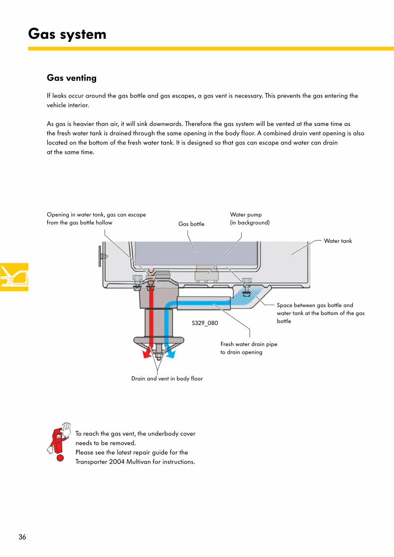
Gas system
Gas venting
If leaks occur around the gas bottle and gas escapes, a gas vent is necessary. This prevents the gas entering the vehicle interior.
As gas is heavier than air, it will sink downwards. Therefore the gas system will be vented at the same time as the fresh water tank is drained through the same opening in the body floor. A combined drain vent opening is also located on the bottom of the fresh water tank. It is designed so that gas can escape and water can drain at the same time.
Water tank
Gas bottle
Water pump (in background)
Fresh water drain pipe to drain opening
Drain and vent in body floor
Space between gas bottle and water tank at the bottom of the gas bottle
Opening in water tank, gas can escape from the gas bottle hollow
S329_080
To reach the gas vent, the underbody cover needs to be removed. Please see the latest repair guide for the Transporter 2004 Multivan for instructions.

37
Electrical system
California 2004 electrical system
The onboard supply in the California 2004 is made up of the Transporter 2004 onboard supply taken from the Multivan and a special onboard supply system for the California. The California onboard supply consists of a 12 volt wiring harness and a 230 volt wiring harness.
12 volt wiring
230 volt wiring
S329_053
The consumers in the cupboard are supplied by the 12 volt California onboard supply. Furthermore the whole 230 volt onboard supply is located inside the cupboard. The wiring for this section of the onboard supply is shown below. The 12 volt California wiring harness in the cupboard is connected to the rest of the onboard supply via a connector in the cupboard underneath the sink unit.
Wiring in cupboard
Work may only be carried out on the 230 volt onboard supply by authorised personnel.
17-pin connector
230 volt wiring
12 volt wiring
When repair work is carried out, the 230V voltage supply should never be connected at the exterior socket.

38
Electrical system
California 12-Volt onboard supply
The California onboard supply has been taken from the Transporter 2004 Multivan. The power for the equipment and components is supplied via a special California onboard supply, however. This system is not CAN-compatible.
Right interior light W17
Rear right interior light W48
Kitchenette light 1 W57
230V exterior socket U8
Water level sender G120
Water pump V36
Battery for special vehicle A24
Ambient temperature sender 2 G249Refrigerator box J689
Onboard supply charger unit A11
S329_072
39
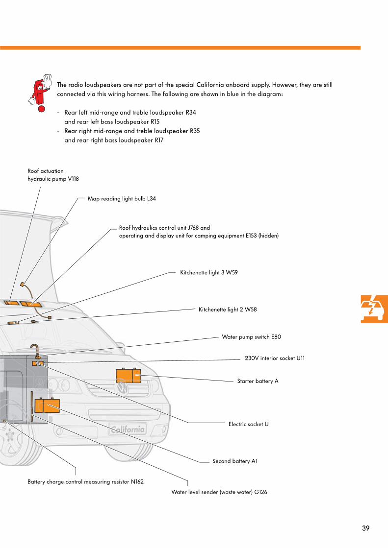
Roof actuation hydraulic pump V118
Map reading light bulb L34
Roof hydraulics control unit J768 andoperating and display unit for camping equipment E153 (hidden)
Kitchenette light 3 W59
Kitchenette light 2 W58
Water pump switch E80
Electric socket U
Second battery A1
Water level sender (waste water) G126
Battery charge control measuring resistor N162
230V interior socket U11
Starter battery A
The radio loudspeakers are not part of the special California onboard supply. However, they are still connected via this wiring harness. The following are shown in blue in the diagram:
- Rear left mid-range and treble loudspeaker R34 and rear left bass loudspeaker R15
- Rear right mid-range and treble loudspeaker R35 and rear right bass loudspeaker R17
40
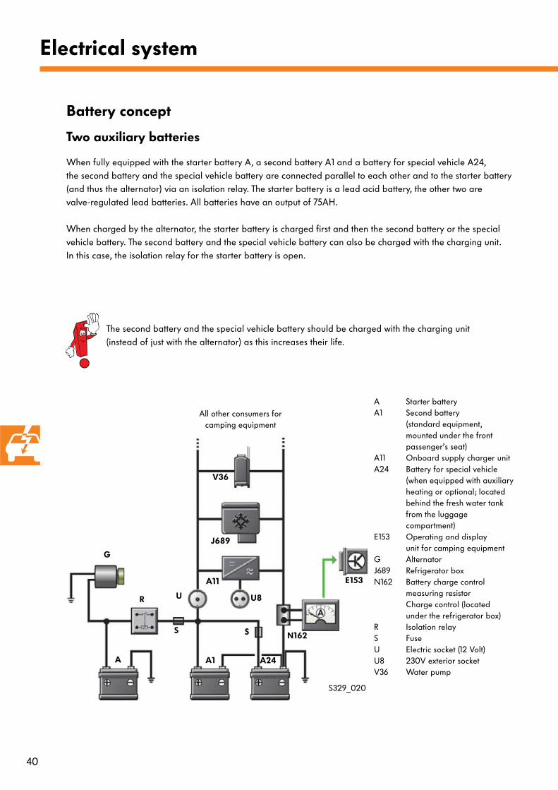
A Starter batteryA1 Second battery
(standard equipment, mounted under the frontpassenger’s seat)
A11 Onboard supply charger unit A24 Battery for special vehicle
(when equipped with auxiliaryheating or optional; locatedbehind the fresh water tankfrom the luggage compartment)
E153 Operating and displayunit for camping equipment
G AlternatorJ689 Refrigerator boxN162 Battery charge control
measuring resistor Charge control (locatedunder the refrigerator box)
R Isolation relayS FuseU Electric socket (12 Volt) U8 230V exterior socket V36 Water pump
Electrical system
Battery concept
When fully equipped with the starter battery A, a second battery A1 and a battery for special vehicle A24, the second battery and the special vehicle battery are connected parallel to each other and to the starter battery (and thus the alternator) via an isolation relay. The starter battery is a lead acid battery, the other two are valve-regulated lead batteries. All batteries have an output of 75AH.
When charged by the alternator, the starter battery is charged first and then the second battery or the special vehicle battery. The second battery and the special vehicle battery can also be charged with the charging unit. In this case, the isolation relay for the starter battery is open.
S329_020
G
A A24A1
E153
N162
A11
U8R
SS
Two auxiliary batteries
The second battery and the special vehicle battery should be charged with the charging unit (instead of just with the alternator) as this increases their life.
V36
J689
U
All other consumers forcamping equipment
41
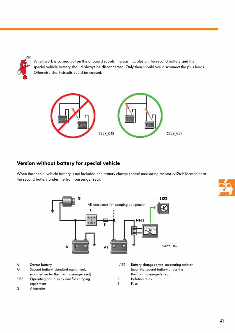
Version without battery for special vehicle
When the special vehicle battery is not included, the battery charge control measuring resistor N126 is located near the second battery under the front passenger seat.
S329_049
A Starter batteryA1 Second battery (standard equipment,
mounted under the front passenger seat)E153 Operating and display unit for camping
equipmentG Alternator
G
A A1
E153
N162S
When work is carried out on the onboard supply, the earth cables on the second battery and the special vehicle battery should always be disconnected. Only then should you disconnect the plus leads.Otherwise short-circuits could be caused.
S329_021S329_048
R
All consumers for camping equipment
N162 Battery charge control measuring resistor (near the second battery under the the front passenger’s seat)
R Isolation relayS Fuse

42
Electrical system
When the special vehicle battery A24 is not included, the battery charge control measuring resistor N126 is located near the second battery under the front passenger seat in the seat box. When equipped with the starter battery A, the second battery A1 and the battery for special vehicle A24, the measuring resistor is located in the cupboard under the refrigerator box. The measuring resistors, also called “shunts”, are used to determined the actual current flowing through the wires. The values obtained are used to calculate the percentage that is shown as the remaining battery capacity on the operating and display unit for camping equipment E153.
Battery charge control measuring resistor N162
S329_063
Arrangement and operation
The battery charge control measuring resistor N126 measures the current using a constant resistor on which the voltage drop can be recorded. The measuring resistor has a piece of sheet metal with a constant resistance via which the current is conducted. The voltage is measured at two pins. If the current changes, the voltage drop will also vary when the resistance is constant. The voltage difference is recognised by the operating and display unit for camping equipment E153. Using the data the operating and display unit for camping equipment calculates the value of the current. It is also possible to calculate how long the capacity of the batteries will last for the respective current load.
Basic formula “Ohm’s Law”
R =U
I
U = VoltageR = ResistanceI = Current (in this case: the current actually flowing)
I =U
RU = R* I
R=0.2 Ω
I1 =0.1V
0.2 Ω
I1 = 0.5 A
Case 1:
I2 =0.09V
0.2 Ω
I2 = 0.45 A
Case 2 (change to voltage):
Calculation of I:
Calculation of I:
+
+
-
-
I1
I2 (<I1)
Connections for 12 voltonboard supply
Cables to operating and display unit for camping equipment
Sheet with constant resistance
S329_094
S329_094
R=0.2 Ω
U=0.1V
U=0.09V

43
230-volt onboard supply
A 230-volt onboard supply has been installed in the California. The 230-volt onboard supply consists of a 230V exterior socket (mains connection) U8, an automatic personal protection circuit-breaker S59 (also known as a residual-current-operated circuit-breaker), a 230-volt interior socket U11 and a connection to the battery charging unit.
S329_018
U8
S59
U11
A11
Alternating voltage 230V
Earth conductor
A11 = Onboard supply charger unit
S59 = 230V automatic personal protectioncircuit-breaker
U8 = 230V exterior socket (mains connection)
U11 = 230V interior socket
Connection to 12 volt onboard supply
To connector in cupboard: Signal cable to operating and
display unit for camping equipment E153
Earth connection
The automatic personal protection circuit-breaker has a switch that has to be pressed approx. once per quarter to check it is working properly.
When repair work is carried out, the 230V voltage supply should never be connected at the exterior socket.
Any repair work on the 230V system should only be carried out by an electrician or under the instruction of an electrician.
Local national regulations should be observed.
44
Connectors for the 12-volt onboard supply
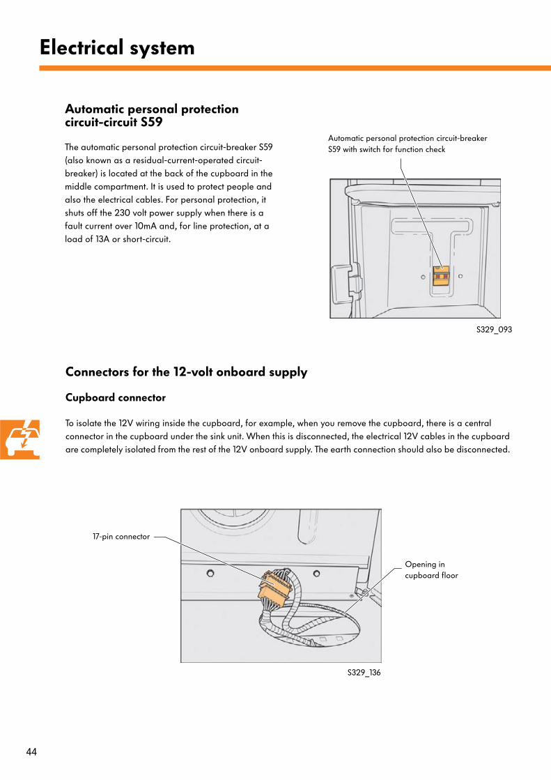
Cupboard connector
To isolate the 12V wiring inside the cupboard, for example, when you remove the cupboard, there is a central connector in the cupboard under the sink unit. When this is disconnected, the electrical 12V cables in the cupboard are completely isolated from the rest of the 12V onboard supply. The earth connection should also be disconnected.
Electrical system
Automatic personal protection circuit-circuit S59
The automatic personal protection circuit-breaker S59 (also known as a residual-current-operated circuit-breaker) is located at the back of the cupboard in the middle compartment. It is used to protect people and also the electrical cables. For personal protection, it shuts off the 230 volt power supply when there is a fault current over 10mA and, for line protection, at a load of 13A or short-circuit.
S329_093
Automatic personal protection circuit-breaker S59 with switch for function check
17-pin connector
Opening in cupboard floor
S329_136

45
Connectors under driver’s seat
Connectors under the front passenger seat
S329_097
S329_096
1 2 3 4 5
6 7 8 9 10
1 2 3 4 5
6 7 8 9 10
In the seat box under the driver’s seat, there is a connector for the special California onboard supply wiring. The second battery A1 is also in the seat box.
In the seat box under the front passenger seat, there is a connector for the loudspeakers in the overhead storage compartment . There is also space for special equipment like a CD changer and a digital sound package in the seat box.
Connectors for special Californiaonboard supply
Second battery A1
Space for special equipment,e.g. CD changer
Connector for loudspeakers inthe overhead storage
compartment
1
6 7
Fuses for special Californiaonboard supply

46
Electrical system
Operating and display unit for camping equipment E153The operating and display unit for camping equipment, the central electronics for the special California onboard supply, is located in the roof of the driver’s cab. It controls the components specific to the California, evaluates information and is the interface with the occupants. The menu in the display unit has been prepared for use of a solar module. The following components are connected or the following data is evaluated:
- the pop-up roof electrohydraulics- the refrigerator box - the auxiliary heating - the status of the batteries - the level of the fresh water and waste water tanks- the ambient temperature
The following connections are located on the back of the operating and display unit for camping equipment:
- a 32-pole central connector- two connectors for the auxiliary heating, which is
also controlled via the operating and display unit for camping equipment.
S329_026
Wednesday
S329_058
Central connector
Connectors for auxiliary heating

47
System overview
Battery charge control measuring resistor N162
Onboard supply charger unit A11
Ambient temperature sender 2 G249
Water level sender (waste water) G126
Water level sender G120
Roof hydraulics control unit J768
Refrigerator box J698(temperature gauge)
Roof hydraulics control unit J768
Refrigerator box J689(temperature control)
Auxiliary heating
S329_039
Operating and display unit for camping equipment E153
Onboard supply charger unit A11
The onboard supply charger unit A11 is located between the refrigerator box and its compressor. It can be accessed by removing a cover in the cupboard under the gas stove. When the onboard supply unit is connected, the onboard supply charger unit ensures that the second battery A1 and the battery for special vehicle A24 are charged.
S329_138
Input signal
Output signal

48
Controls
Button Function
This button switches the display of the operating and display unit for camping equipment on and off. It also switches off all special California consumers (refrigerator box and auxiliary heating).
This rotary press knob is used to select menu options by turning it to select and pressing to confirm entries.
The Escape button cancels without saving.
This button controls the refrigerator box. If the refrigerator box is turned off when you press the button, the temperature setting will be called up. Once you have set the required temperature, you can turn on the refrigerator box by pressing the rotary press knob. When the refrigerator box is switched on, this button will switch it off.
This button controls the auxiliary heating. If it is turned off when you press the button, the temperature setting will be called up. Once you set the required temperature, switch on the auxiliary heating by turning the rotary press knob. When the auxiliary heating is switched on, this button will switch it off. (This button is also present when auxiliary heating is not installed in the vehicle. In this case, it will have not any function.)
Electrical system
Layout of the operating and display unit for camping equipment E153.
Display for“Refrigerator Box”
Central display area
Display for“Energy Supply”
Display for“Roof”
Display for“Waste Water Level”
Display for“Fresh Water Level”
Display for“Auxiliary Heating”
S329_040
S329_043
S329_047
S329_045
S329_044
Wednesday
S329_046

49
Display functions
Icon Function
Auxiliary heating: This icon appears in the display when the auxiliary heating is switched on. If it is faulty, the icon will flash. Ten temperature levels can be selected for the auxiliary heating.
Fresh water tank: This icon indicates the level of the fresh water tank in four steps 3/3 full, 2/3 full, 1/3 full and empty. If the fresh water sender is faulty, the icon will start flashing.
Waster water tank: This icon indicates whether the waste water tank is full or empty. If the waste water sender is faulty, the icon will start flashing.
Refrigerator box: This icon appears in the display when the refrigerator box is switched on. If it is faulty, the icon will flash.
Electrohydraulic pop-up roof This icon indicates whether the electrohydraulic pop-up roof is closed,...
...in an intermediate state
...or is open.
If there is a fault, the icon will flash.
Wednesday
Wednesday
Wednesday
Wednesday
Wednesday
Wednesday
Wednesday
S329_123
S329_124
S329_125
S329_126
S329_128
S329_127
S329_129

50
Electrical system
Display functions
Icon Function
Battery: In the “Energy Supply” display area, this icon indicates firstly when energy is being supplied by the batteries. In the central display area, it indicates the remaining battery level.
Mains plug: In the “Energy Supply” section, this icon indicates that the mains plug is connected to the vehicle.
Ambient temperature: This icon indicates that the ambient temperature is being displayed.
Alarm clock: This icon appears in the central display area when the time is displayed and an alarm time has been set.
12.2 V 100 %0.0 A
Wed
Wednesday
Wed
19.5 °C
Wednesday
S329_131
S329_130
S329_133
S329_134
Display illumination
If a button is not pressed, the display illumination switches off after a brief period and can be switched on again by pressing a button once.
S329_152

51
Main menu
The submenus can be called up with the rotary press knob. The example adjacent shows the “Pop-up Roof” menu.
Pop-up roof
Back1. Open2. Close
S329_057
The main menu for the operating and display unit for camping equipment has the following items:
- Auxiliary heating: Operation of the auxiliary heating.
- Pop-up roof: Operation of the pop-up roof. - Clock: Setting the time and alarm. - Back: Back to the previous menu,
in this case to the main screen. - Display: Selection of which information
should appear in the display. - Refrigerator box: Operation of the refrigerator box.
Submenus
Menu
S329_145
Auxiliary heating
Pop-up roof
Clock
Back
Display
Refrigerator box
The non-public menu contains options for workshops. It is opened by pressing the Escape button (for longer than a second) and pressing the rotary press knob at the same time. Items in the non-public menu:
- Back- Diagnosis - Battery 2 - Variants (basic settings for temperature
and clock display) - Language
Non-public menu
Back
Diagnosis
Battery 2
Variants
LanguageS329_151
52
Electrical system
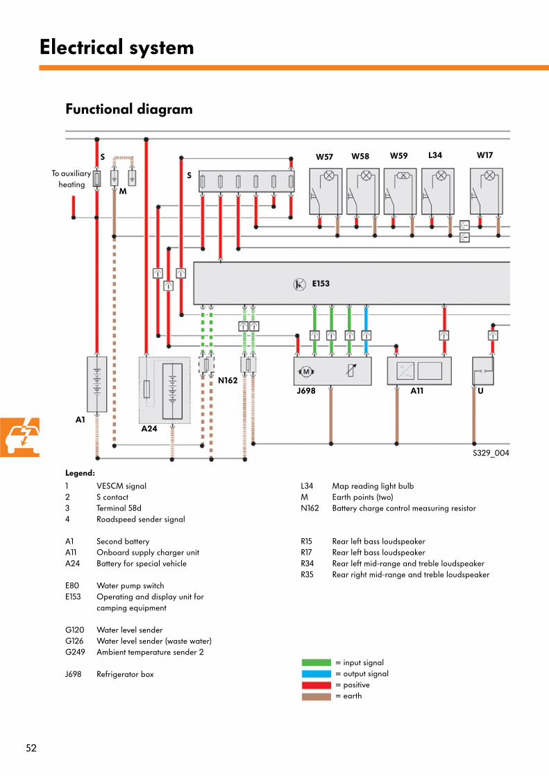
Functional diagram
= input signal= output signal= positive= earth
1 VESCM signal2 S contact3 Terminal 58d4 Roadspeed sender signal
A1 Second battery A11 Onboard supply charger unit A24 Battery for special vehicle
E80 Water pump switch E153 Operating and display unit for
camping equipment
G120 Water level sender G126 Water level sender (waste water) G249 Ambient temperature sender 2
J698 Refrigerator box
S329_004
E153
A1
S
S
W57 W58 W59 L34
M
L34 Map reading light bulbM Earth points (two)N162 Battery charge control measuring resistor
R15 Rear left bass loudspeaker R17 Rear left bass loudspeaker R34 Rear left mid-range and treble loudspeaker R35 Rear right mid-range and treble loudspeaker
Legend:
To auxiliary heating
A24
W17
N162J698 A11 U

53
S Fuse
T10bk 10-pin connector, brown Coupling station under driver’s seat
T10u 10-pin connector, blue Coupling station under driver’s seat
T17b 17-pin connector, black
U Electric socket
V36 Water pump V118 Roof actuation hydraulic pump
W17 Right interior lightW48 Rear right interior light W57 Kitchenette light 1 W58 Kitchenette light 2 W59 Kitchenette light 3
S329_005
W48
Legend:
V118
T10u
V36
E80
G120 G126 G249
E153
T10bk
T10bk
12
3
4
R15 R34
R35 R17
Only when equipped with A1 and A24
Only when not equipped with A24
Connected via a connector (T17b) in the cupboard base under the sink unit. This connector isolates the wiring in the cupboard from the other special California system.
1
2
To radio
To radio
54
Heating and air conditioning
Air conditioning in the California
The California comes with a manual air-conditioning system (Climatic) as standard. 3-zone air conditioning (3C-Climatronic) is available as an option. Except for the vents in the rear, the air conditioning has been taken from the Transporter 2004 Multivan. The vents in the B-pillar that are standard in the Transporter 2004 Multivan, as well as the booster function are not featured in the California due to the different vehicle equipment.
Auxiliary heating in the California
The are three possibilities for auxiliary heating in the California.
1. A fuel-operated preheater that preheats the coolant without the driver noticing to improve the start phase of diesel engines.
2. Upgrading the preheater to auxiliary coolant heating. This heating system allows presetting and remote control (for heating and ventilation) with a limit of 30 min running time.
3. Installing fuel-operated auxiliary air heating is another option for air conditioning. This function can be operated from the operating and display unit for camping equipment. The running time is not limited.
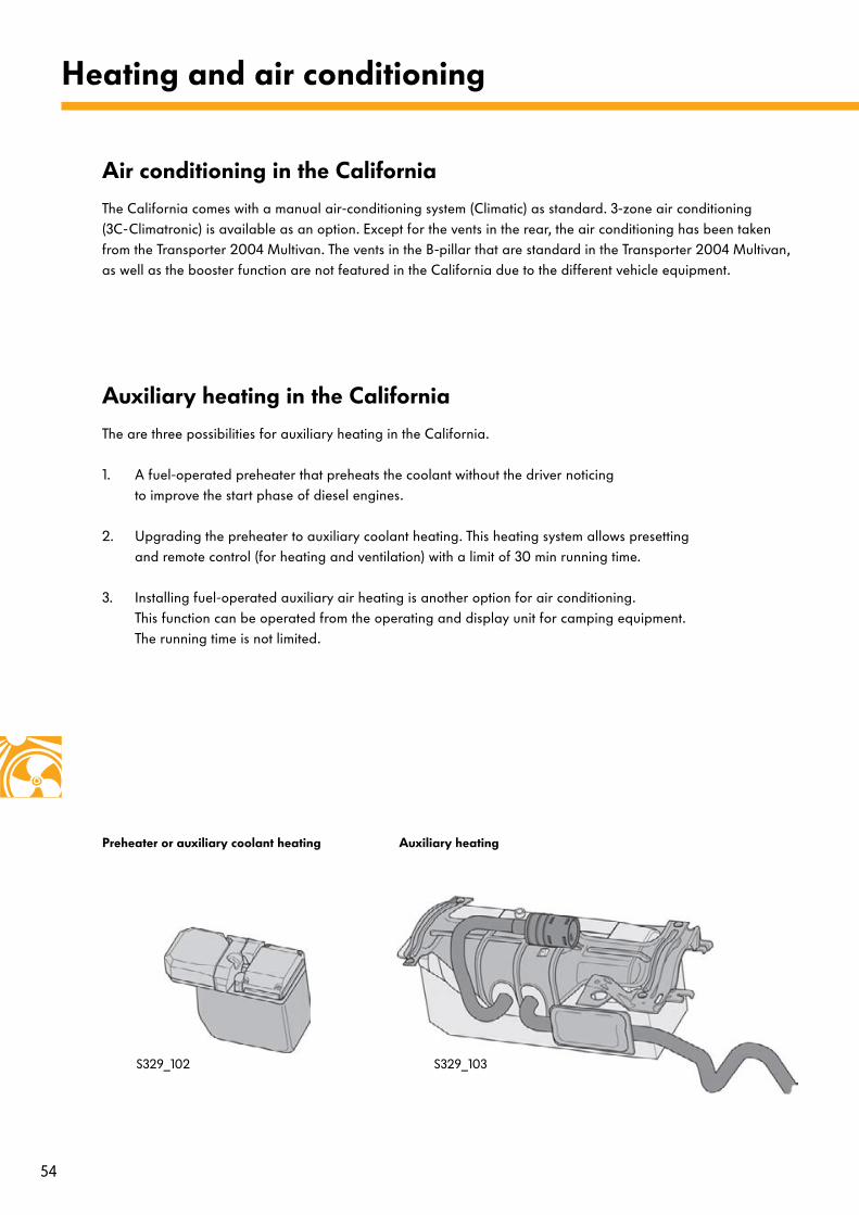
Auxiliary heatingPreheater or auxiliary coolant heating
S329_103S329_102
55
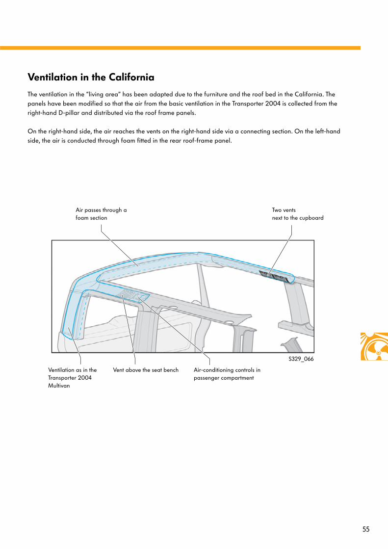
Ventilation in the California
The ventilation in the “living area” has been adapted due to the furniture and the roof bed in the California. The panels have been modified so that the air from the basic ventilation in the Transporter 2004 is collected from the right-hand D-pillar and distributed via the roof frame panels.
On the right-hand side, the air reaches the vents on the right-hand side via a connecting section. On the left-hand side, the air is conducted through foam fitted in the rear roof-frame panel.
Two vents next to the cupboard
Air passes through a foam section
Air-conditioning controls in passenger compartment
Vent above the seat benchVentilation as in the Transporter 2004 Multivan
S329_066

© VOLKSWAGEN AG, Wolfsburg, VK-21 Service Training
All rights and rights to make technical alterations reserved
000.2811.45.20 Technical status 05/2004
This paper was manufacturer from pulp that
was bleached without the use of chlorine.
329