Embed Size (px)
Citation preview
REFERENCE : DATE :
EXM-M2-RQM-AI-0078 16/04/2015
ISSUE : 1.0 Page : 2/63
THALES ALENIA SPACE INTERNAL
This document is not to be reproduced, modified, adapted, published, translated in any material form in whole or in part nor disclosed to any third party without the prior written permission of Thales Alenia Space.
2015, Thales Alenia Space Template 83230326-DOC-TAS-EN/002
CHANGE RECORD
ISSUE DATE § CHANGE RECORDS AUTHOR
1 16/01/2014 First issue D.ROLFO
REFERENCE : DATE :
EXM-M2-RQM-AI-0078 16/04/2015
ISSUE : 1.0 Page : 3/63
THALES ALENIA SPACE INTERNAL
This document is not to be reproduced, modified, adapted, published, translated in any material form in whole or in part nor disclosed to any third party without the prior written permission of Thales Alenia Space.
2015, Thales Alenia Space Template 83230326-DOC-TAS-EN/002
TABLE OF CONTENTS
1. INTRODUCTION .................................................................................................................. 5
1.1 Purpose ......................................................................................................................................................5
1.2 Acronyms ...................................................................................................................................................5
1.3 Applicability ...............................................................................................................................................6
1.4 Conventions...............................................................................................................................................6
1.5 Verification methods definition................................................................................................................6 1.5.1 Assessment, review of Design (R)..........................................................................................................6 1.5.2 Analysis (A) .............................................................................................................................................6 1.5.3 Similarity (S)............................................................................................................................................6 1.5.4 Test (T)....................................................................................................................................................7
1.6 Verification Levels.....................................................................................................................................7 1.6.1 Sub-System level (SS)............................................................................................................................7 1.6.2 Equipment level (EQ)..............................................................................................................................7
1.7 Reasons of change ...................................................................................................................................7
2. DOCUMENTS....................................................................................................................... 8
2.1 Normative Documents ..............................................................................................................................8 2.1.1 ESA Normative Documents ....................................................................................................................8 2.1.2 Prime Normative Documents ..................................................................................................................8
2.2 Informative Documents ............................................................................................................................8
2.3 Specific Reference documents................................................................................................................8
3. SCC MIL-1553 SYSTEM DATA BUSSES............................................................................ 9
3.1 Remote Terminals Description ..............................................................................................................11 3.1.1 Carrier Module: Remote Terminal Unit (CRTU)....................................................................................11 3.1.2 Carrier Module: Power Control and Distribution Unit (CPCDU) ...........................................................11 3.1.3 Carrier Module: X-Band Deep Space Transponder (X-DST)................................................................11 3.1.4 Carrier Module: Star Tracker (STR)......................................................................................................11 3.1.5 Descent Module: Thruster Control Unit (TCU)......................................................................................12 3.1.6 Descent Module: Power Control Unit (PCU).........................................................................................12 3.1.7 Descent Module: Control Unit (CU) ......................................................................................................12 3.1.8 Descent Module: Inertial Measurement Unit (IMU)...............................................................................12 3.1.9 ROS-OBC (ROS) ..................................................................................................................................12
3.2 General Conventions ..............................................................................................................................13 3.2.1 Bit and field numbering conventions .....................................................................................................13 3.2.2 Subaddresses .......................................................................................................................................13 3.2.3 Meaning of RT/Instrument ....................................................................................................................14 3.2.4 Meaning of BC ......................................................................................................................................14
REFERENCE : DATE :
EXM-M2-RQM-AI-0078 16/04/2015
ISSUE : 1.0 Page : 4/63
THALES ALENIA SPACE INTERNAL
This document is not to be reproduced, modified, adapted, published, translated in any material form in whole or in part nor disclosed to any third party without the prior written permission of Thales Alenia Space.
2015, Thales Alenia Space Template 83230326-DOC-TAS-EN/002
3.3 Physical Layer .........................................................................................................................................14 3.3.1 Data bus Requirements ........................................................................................................................14 3.3.2 Terminal Requirements.........................................................................................................................16
3.4 Data Link Layer........................................................................................................................................18 3.4.1 General Requirements..........................................................................................................................18
3.4.1.1 Bus Controller (BC) Functions......................................................................................................25 3.4.1.2 Remote Terminal Functions .........................................................................................................27 3.4.1.3 Message Format and Word Formats ...........................................................................................28 3.4.1.4 Message Timing ...........................................................................................................................30
3.4.2 Command Word ....................................................................................................................................31 3.4.2.1 RT Address Field..........................................................................................................................32 3.4.2.2 T/R Bit Field..................................................................................................................................33 3.4.2.3 Subaddress/Mode Field ...............................................................................................................34
3.4.3 RT Status Word.....................................................................................................................................35 3.4.3.1 Status Word bits ...........................................................................................................................35
3.4.4 Data Word .............................................................................................................................................37 3.4.5 Data Link Layer FDIR............................................................................................................................37
3.4.5.1 Management of Bus Errors ..........................................................................................................37
3.5 Transfer Layer..........................................................................................................................................40 3.5.1 General .................................................................................................................................................40 3.5.2 Time Protocol ........................................................................................................................................40 3.5.3 Communication Synchronization ..........................................................................................................41 3.5.4 Set Command Word..............................................................................................................................43 3.5.5 Get Data Word ......................................................................................................................................44 3.5.6 Data Block Transfer ..............................................................................................................................46
3.5.6.1 Data Distribution...........................................................................................................................46 3.5.6.2 Data Acquisition ...........................................................................................................................52
3.5.7 Transfer Layer FDIR .............................................................................................................................59

REFERENCE : DATE :
EXM-M2-RQM-AI-0078 16/04/2015
ISSUE : 1.0 Page : 5/63
THALES ALENIA SPACE INTERNAL
This document is not to be reproduced, modified, adapted, published, translated in any material form in whole or in part nor disclosed to any third party without the prior written permission of Thales Alenia Space.
2015, Thales Alenia Space Template 83230326-DOC-TAS-EN/002
1. INTRODUCTION
1.1 Purpose
This document specifies the tailoring of MIL-STD 1553B protocol for ExoMars 2018 mission.
1.2 Acronyms
The general EXOMARS 2018 acronyms list is specified in [NR 05002] EXM-M2-LIS-AI-0059. The following acronyms list is dedicated to the MIL-STD-1553B protocol: Acronyms Meaning ABC Acquisition Block Count ACC Accelerometer ATR Acquisition Transfer Request BPSK Binary Phase-Shift Keying BTS Bus Time Slot CAN Controller Area Network CCSDS Consultative Committee for Space Data System CF Communication Frame CUC CCSDS Unsegmented time Code DBC Distribution Block Count DMR Double Module Redundancy DTD Distribution Transfer Descriptor FIFO First In First Out GYR Gyroscope IDS Interface Data Sheet LSB Least Significant Bit MSB Most Significant Bit NRZ Non Return to Zero PPS Pulse Per Second QoS Quality of Service SA SubAddress SCC SpaceCraft Composite SFO Selected For Operations SFR Selected For Receovery SGDA Solar Generator Deployment Actuators TM TeleMetry TMR Triple Module Redundancy TMS TeleMetry System T/R Transmit/Receive TS Time Slice
REFERENCE : DATE :
EXM-M2-RQM-AI-0078 16/04/2015
ISSUE : 1.0 Page : 6/63
THALES ALENIA SPACE INTERNAL
This document is not to be reproduced, modified, adapted, published, translated in any material form in whole or in part nor disclosed to any third party without the prior written permission of Thales Alenia Space.
2015, Thales Alenia Space Template 83230326-DOC-TAS-EN/002
1.3 Applicability
The document is applicable to all the ExoMars 2018 on-board units interfaced to the MIL-STD 1553B. Each sub-contractor shall demonstrate compliance to this document.
1.4 Conventions
A requirement or group of requirements may be followed or preceded by comments, i.e. an explanatory text. This is intended only to assist the understanding of the requirement or its origin. This text, which is indicated in italic characters and starts with “NOTE:” may describe the context in which a requirement has to be understood, explain the rationale for the requirement or refer to the source of this requirement.
1.5 Verification methods definition
The verification methods are assessment, analysis, similarity, test, or a combination thereof. The allocation of these methods is based upon design analyses, design maturity, complexity of the item, criticality category and associated cost. Testing is the primary method used to verify performance.
1.5.1 Assessment, review of Design (R)
Assessment is a method of verification that determines conformance to requirements through inspection or review of design. Inspection uses standard quality control methods to verify compliance with requirements of construction features, document and drawing compliance, workmanship standards, and physical condition without the use of special laboratory equipment, procedures, test support items or services. Emphasis is on observation of physical characteristics rather than performance. Review-of-design is verification method in which verification is achieved by validation of records or by evidence of validated design documents or when approved design reports, technical descriptions, engineering drawings unambiguously show the requirement is met.
1.5.2 Analysis (A)
Verification by analysis is a process used in lieu of, or in addition to, other verification methods to verify compliance to specification requirements. The selected techniques may include, but not be limited to, engineering analysis, statistics and qualitative analysis, computer and hardware simulations, and analogue modelling. Analysis may be used when it can be determined that (1) rigorous and accurate analysis is possible, (2) test is not cost effective, and (3) verification by inspection is not adequate.
1.5.3 Similarity (S)
Similarity is the verification method referred when the article under verification is similar in design, manufacturing process, and quality control to another article that has already been verified to equivalent or more stringent requirements. The verification activity consists of the assessment and review of prior test data, hardware configuration and application.
REFERENCE : DATE :
EXM-M2-RQM-AI-0078 16/04/2015
ISSUE : 1.0 Page : 7/63
THALES ALENIA SPACE INTERNAL
This document is not to be reproduced, modified, adapted, published, translated in any material form in whole or in part nor disclosed to any third party without the prior written permission of Thales Alenia Space.
2015, Thales Alenia Space Template 83230326-DOC-TAS-EN/002
In case Similarity method is proposed an exhaustive list of differences of the article under verification and the one considered similar. The approval of similarity shall be agreed with Prime contractor. If the previous application is considered to be similar, but not equal to or greater in severity, additional qualification tests shall concentrate on the areas of new or increased requirements.
1.5.4 Test (T)
Test is a method of verification in which technical means, such as the use of special equipment, instrumentation, simulation techniques, and the application of established principles and procedures are used for the evaluation of components, subsystems and systems to determine compliance with requirements. Testing is selected as the prime method of requirements verification and shall be used when analytical techniques do not produce adequate results; failure modes exist which could compromise personnel safety, adversely affect flight systems or payload operation, or result in a loss of mission objectives. The analysis of data derived from tests is an integral part of the test program, and should not be confused with analysis as defined above.
1.6 Verification Levels
The different verification activities will be conducted at equipment, sub-system or system level. The verification programme shall ensure the coherence and the compliance of all these verification steps in order to ascertain that the full verification process covers entirely the specification requirements. The identification of the verification levels is driven by technical and programmatic considerations having in mind that verification will be performed by the manufacturer or contractor responsible for the AIV task of the corresponding level.
1.6.1 Sub-System level (SS)
This corresponds to the MIL-STD 1553B network sub system, composed of all CAN nodes which will belong to that MIL-STD 1553B network. This level is considered representative for all interfaces and communication data of real units. The purpose is also to test FDIR functions and critical situations. For this purpose the test in the avionic test bench is considered a test at Sub-System Level to be performed by the prime without involving the supplier.
1.6.2 Equipment level (EQ)
This corresponds to the single unit that is viewed as an entity for purposes of requirements specification, analysis, manufacturing, testing and maintenance; it is generally the lowest level identified by a configuration item number. In this specification the Equipment Level (EQ) is intended as the specific MIL-STD 1553B terminal and it is responsibility of the supplier.
1.7 Reasons of change
Issue 1.
REFERENCE : DATE :
EXM-M2-RQM-AI-0078 16/04/2015
ISSUE : 1.0 Page : 8/63
THALES ALENIA SPACE INTERNAL
This document is not to be reproduced, modified, adapted, published, translated in any material form in whole or in part nor disclosed to any third party without the prior written permission of Thales Alenia Space.
2015, Thales Alenia Space Template 83230326-DOC-TAS-EN/002
2. DOCUMENTS
2.1 Normative Documents
Normative References are directly applicable in their entirety to this document and are listed below. These normative references may be referenced at appropriate places in the text. In case of conflict between this document and normative documents listed herein the Contractor shall inform the Prime Contractor for resolution.
2.1.1 ESA Normative Documents
2.1.2 Prime Normative Documents
In this section the EXOMARS 2018 applicable documents are listed. [NR 05004] EXOMARS 2018 Electrical General Design and
Interface Requirements EXM-M2-SSR-AI-0023
[NR 05008] EXOMARS 2018 PA Requirements for Subcontractors EXM-M2-RQM-AI-0067
[NR 1117] EXOMARS On Board Communication Protocols EXM-MS-RQM-AI-0028
2.2 Informative Documents
Informative References are applicable to this document only when specifically called up in the text with specific indications of the parts of the document that are to be applicable. Otherwise the documents are listed below for information only as an aid for the purpose of understanding.
2.3 Specific Reference documents
Specific References are applicable to this document only when specifically called up in the text with specific indications of the parts of the document that are to be applicable. Otherwise the documents are listed below for information only as an aid for the purpose of understanding. [LR 0001] Interface standard for digital/time division
command/response multiplex data bus MIL-STD-1553B, Notice 4, 15/01/1996
REFERENCE : DATE :
EXM-M2-RQM-AI-0078 16/04/2015
ISSUE : 1.0 Page : 9/63
THALES ALENIA SPACE INTERNAL
This document is not to be reproduced, modified, adapted, published, translated in any material form in whole or in part nor disclosed to any third party without the prior written permission of Thales Alenia Space.
2015, Thales Alenia Space Template 83230326-DOC-TAS-EN/002
3. SCC MIL-1553 SYSTEM DATA BUSSES
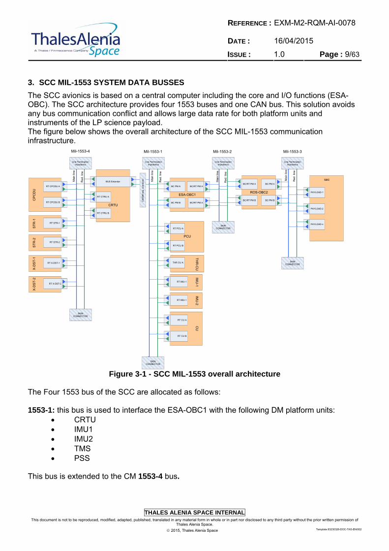
The SCC avionics is based on a central computer including the core and I/O functions (ESA-OBC). The SCC architecture provides four 1553 buses and one CAN bus. This solution avoids any bus communication conflict and allows large data rate for both platform units and instruments of the LP science payload. The figure below shows the overall architecture of the SCC MIL-1553 communication infrastructure.
CRTU
RT CTRU A
RT CTRU B
RT CPCDU A
RT CPCDU B
RT STR-1
RT STR-2
RT X-DST-1
RT X-DST-2
CP
CD
US
TR
-1S
TR
-2X
-DS
T-1
X-D
ST
-2
BC/RT PM A
ESA-OBC1
BC PM A
BC/RT PM ABC PM B
BC PM A
ROS-OBC2
BC/RT PM A
BC PM BBC/RT PM B
sec
PAYLOAD-1
PAYLOAD-2
Line Termination impedance
Line Termination impedance
SKIN CONNECTOR
SKIN CONNECTOR
Line Termination impedance
SKIN CONNECTOR
Line Termination impedance
SKIN CONNECTOR
PAYLOAD-n
Mil-1553-1 Mil-1553-2 Mil-1553-3Mil-1553-4
Mai
n lin
e
Red
. lin
e
Mai
n lin
e
Red
. lin
e
Mai
n lin
e
Red
. lin
e
Mai
n lin
e
Red
. lin
e
BUS Extender
TH
R-C
U
RT PCU A
PCU
RT PCU B
THR CU A
RT IMU-1
IMU
-1
RT IMU-1
IMU
-2
RT CU A
RT CU B
CU
CM
/DM
se
p.
con
ne
cto
r
Figure 3-1 - SCC MIL-1553 overall architecture
The Four 1553 bus of the SCC are allocated as follows: 1553-1: this bus is used to interface the ESA-OBC1 with the following DM platform units:
CRTU IMU1 IMU2 TMS PSS
This bus is extended to the CM 1553-4 bus.
REFERENCE : DATE :
EXM-M2-RQM-AI-0078 16/04/2015
ISSUE : 1.0 Page : 10/63
THALES ALENIA SPACE INTERNAL
This document is not to be reproduced, modified, adapted, published, translated in any material form in whole or in part nor disclosed to any third party without the prior written permission of Thales Alenia Space.
2015, Thales Alenia Space Template 83230326-DOC-TAS-EN/002
1553-4: this bus is a sub-network internal to the CM and logically is the same bus of the 1553-1. It will be used during the cruise phase to interface the ESA-OBC1 with the following CM units:
STR1 STR2 X-DST1 X-DST2 CPCDU
The CRTU will act as bus repeater/extender between the 1553-1 and 1553-4 busses. This solution has been chosen to optimize the bus performances and to minimize the number of 1553 stubs crossing the CM/DM separation connector with the main goal to guarantee the reliability of the 1553-1 bus after the CM to DM separation. 1553-2: this bus is only dedicated to the ESA-OBC1 to ROS-OBC2 interface. This solution has been adopted to avoid any interference between the ROS-OBC2 and the platform activities during the different mission phases. During the EDL phase, the ROS-OBC will be active managing the acquisition of some payload data; in this phase the 1553-2 bus will be disabled by the OBSW to totally decouple the EDL operations from the Scientific operations. During the Mars Surface Operation the role of the ESA-OBC1 and ROS-OBC will be swapped and the ROS-OBC will become the Bus Controller of the 1553-2 bus. 1553-3: this bus is used to interface the ROS-OBC2 with the SEC payloads (DM payloads). NOTE: that this Technical note only covers the 1553-1, 1553-2 and 1553-4 protocol and architecture; the 1553-3 protocol is under LAV responsibility and it is not discussed in this document.

REFERENCE : DATE :
EXM-M2-RQM-AI-0078 16/04/2015
ISSUE : 1.0 Page : 11/63
THALES ALENIA SPACE INTERNAL
This document is not to be reproduced, modified, adapted, published, translated in any material form in whole or in part nor disclosed to any third party without the prior written permission of Thales Alenia Space.
2015, Thales Alenia Space Template 83230326-DOC-TAS-EN/002
3.1 Remote Terminals Description
The following sections provide a short description of the ExoMars 2018 Remote Terminals connected to the SCC MIL-1553 Bus.
3.1.1 Carrier Module: Remote Terminal Unit (CRTU)
The CRTU provides the following functions: Acquisition of Telemetry and House-keeping data; Transfer of Telemetry and house-keeping data to DM for the purpose of thermal control, GNC and downlink to ground; Remote Terminal (RT) functions on the DM MIL-STD-1553B communication bus; MIL-STD-1553B extender function to provide access for DM towards CM subsystems Supporting the DM separation; Supporting the Thermal Control of the Carrier Module; Generation of galvanically isolated power bus for the propulsion pressure transducer; High Power Commanding for AOCS-STR ON/OFF commanding purposes; CRTU own command and control; CRTU own house-keeping generation (status and temperature); CRTU internal FDIR; CRTU internal DC power conversion.
3.1.2 Carrier Module: Power Control and Distribution Unit (CPCDU)
The CPCDU is in charge of managing the electrical energy of the entire ExoMars 2018 S/C (CM+DM) during the entire cruise phase up to the Descent Module separation. It controls the power and provides the power distribution and protections functions for the CM and to the DM PCDU. The CPCDU is performing its tasks autonomously, but it is also controlled by the DM OBC via MIL1553B bus. Bi-Level Status monitoring signals and telemetry data sent across the MIL1553B bus allow the monitoring of the CPCDU internal states, current and voltage levels. In addition to that there are a few direct telemetry lines to the DM OBC.
3.1.3 Carrier Module: X-Band Deep Space Transponder (X-DST)
The SCC will be equipped with two X-band Deep Space Transponders (X-DST), provided with hot redundancy for the receiving functions and cold redundancy for the transmit function. The two X-DSTs will directly interface the ESA-OBC, which decodes and distributes commands to the units and collects, encodes and formats telemetry.
3.1.4 Carrier Module: Star Tracker (STR)
The STR is an autonomous star sensor whose task is to determine its own attitude with respect to an inertial reference system, starting from the image of the stars in the sky. It accepts commands from the ESA-OBC and sends back to it the result of its measurements and status information.
REFERENCE : DATE :
EXM-M2-RQM-AI-0078 16/04/2015
ISSUE : 1.0 Page : 12/63
THALES ALENIA SPACE INTERNAL
This document is not to be reproduced, modified, adapted, published, translated in any material form in whole or in part nor disclosed to any third party without the prior written permission of Thales Alenia Space.
2015, Thales Alenia Space Template 83230326-DOC-TAS-EN/002
3.1.5 Descent Module: Thruster Control Unit (TCU)
The DM Thruster Control Unit is in charge of the acquisition and digital conversion of the DM analog telemetries. It will be directly interfaced with the ESA-OBC via SCC MIL-1553 bus.
3.1.6 Descent Module: Power Control Unit (PCU)
The DM PCU is in charge of the DM power conditioning; it is interfaced with the ESA-OBC via SCC MIL-1553 bus for command and control and with HPC for PCU configuration. The analog monitors will be acquired by the TMS and the data forwarded to the ESA-OBC via the TMS MIL-1553 interface.
3.1.7 Descent Module: Control Unit (CU)
It is in charge of the DM HCCU and propulsion management; it is interfaced with the ESA-OBC via SCC MIL-1553 bus for command and control and with HPC for CU configuration. The analog monitors will be acquired by the TMS and the data forwarded to the ESA-OBC via the TMS MIL-1553 interface.
3.1.8 Descent Module: Inertial Measurement Unit (IMU)
The Descent Module Inertial Measurement Unit (IMU) is defined as a single Equipment that provides:
3-axis angular rate measurement capability 3 axis linear acceleration measurement An attached calibration cube (with a flight cover or removable for flight)
The system shall accommodate 2 IMU units (main and redundant). Each IMU is interfaced with the ESA-OBC via SCC MIL-1553-bus.
3.1.9 ROS-OBC (ROS)
During the CRUISE phase the ROS-OBC2 will be switched ON only for check-outs and possible maintenance. During the Mars surface operations it will became the responsible for the overall LP management. It will be interfaced with the ESA-OBC1 with a dedicated mil-1553 interface (only the ESA-OBC1 and ESA-OBC2 will be connected to this mil-1553 bus).
REFERENCE : DATE :
EXM-M2-RQM-AI-0078 16/04/2015
ISSUE : 1.0 Page : 13/63
THALES ALENIA SPACE INTERNAL
This document is not to be reproduced, modified, adapted, published, translated in any material form in whole or in part nor disclosed to any third party without the prior written permission of Thales Alenia Space.
2015, Thales Alenia Space Template 83230326-DOC-TAS-EN/002
3.2 General Conventions
3.2.1 Bit and field numbering conventions
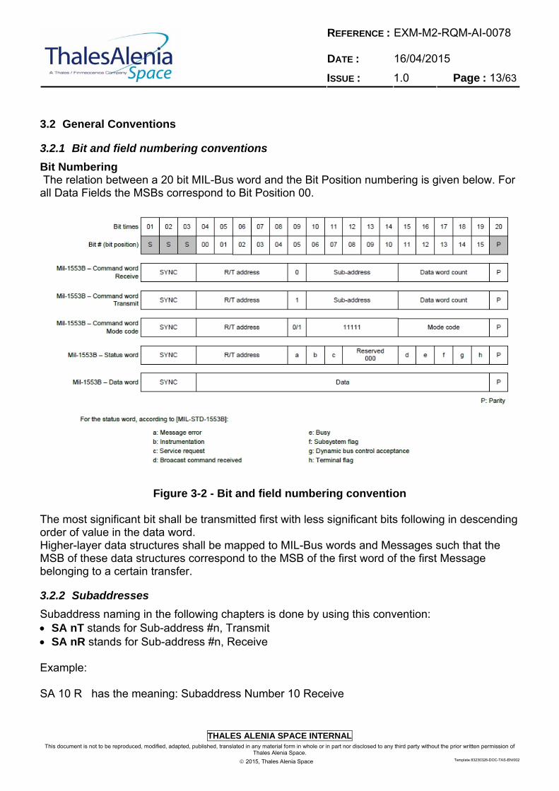
Bit Numbering The relation between a 20 bit MIL-Bus word and the Bit Position numbering is given below. For all Data Fields the MSBs correspond to Bit Position 00.
Figure 3-2 - Bit and field numbering convention
The most significant bit shall be transmitted first with less significant bits following in descending order of value in the data word. Higher-layer data structures shall be mapped to MIL-Bus words and Messages such that the MSB of these data structures correspond to the MSB of the first word of the first Message belonging to a certain transfer.
3.2.2 Subaddresses
Subaddress naming in the following chapters is done by using this convention: SA nT stands for Sub-address #n, Transmit SA nR stands for Sub-address #n, Receive Example: SA 10 R has the meaning: Subaddress Number 10 Receive

REFERENCE : DATE :
EXM-M2-RQM-AI-0078 16/04/2015
ISSUE : 1.0 Page : 14/63
THALES ALENIA SPACE INTERNAL
This document is not to be reproduced, modified, adapted, published, translated in any material form in whole or in part nor disclosed to any third party without the prior written permission of Thales Alenia Space.
2015, Thales Alenia Space Template 83230326-DOC-TAS-EN/002
3.2.3 Meaning of RT/Instrument
The meaning of RT (Remote Terminal)/Instrument, which is in the MIL-STD-1553B only the bus I/F, encloses in the following chapters the RT, and also the attached subsystems, host controllers and so on. Exceptions are explicitly mentioned.
3.2.4 Meaning of BC
The meaning of BC (Bus Controller), which is in MIL-STD-1553B only the bus master, encloses in the following chapters the BC bus I/F, and the Host Controller, and the applications and services behind the bus I/F of the BC.
3.3 Physical Layer
This section aims at defining the requirements of the SCC MIL-1553 Physical Layer. [M2-1553-REQ-0002] [SYS: ] , [SCC: RoD] , [DM: ] , [CM: ] , [RM: ] , [SSS: ] , [EQ: RoD] Traces: The data bus topology, medium, stubs, connectors, shielding and electrical signal characteristics shall comply with [NR 05004] §4.9.4. #
3.3.1 Data bus Requirements
[M2-1553-REQ-0003] [SYS: ] , [SCC: RoD] , [DM: ] , [CM: ] , [RM: ] , [SSS: ] , [EQ: ] Traces: The data bus shall be a twisted-shielded pair transmission line # [M2-1553-REQ-0004] [SYS: ] , [SCC: RoD, T] , [DM: ] , [CM: ] , [RM: ] , [SSS: ] , [EQ: RoD] Traces: The bit rate for SCC MIL-1553 shall be set to 1 Mbit/s NOTE: the 1 Mbit/s bit rate with the bi-phase encoding imposes MIL-1553 controller frequency of 2 MHz #
REFERENCE : DATE :
EXM-M2-RQM-AI-0078 16/04/2015
ISSUE : 1.0 Page : 15/63
THALES ALENIA SPACE INTERNAL
This document is not to be reproduced, modified, adapted, published, translated in any material form in whole or in part nor disclosed to any third party without the prior written permission of Thales Alenia Space.
2015, Thales Alenia Space Template 83230326-DOC-TAS-EN/002
[M2-1553-REQ-0005] [SYS: ] , [SCC: RoD] , [DM: ] , [CM: ] , [RM: ] , [SSS: ] , [EQ: RoD] Traces: The data bus characteristics including stubs shall be in conformance with [LR 0001] § 4.5.1, 30.10.1 and 30.10.2 with the following precisions:
1. The data bus connection using transformer coupled stubs in conformance with [LR 0001] Figure 9, with stub length not exceeding 6 m.
2. The wire-to-wire distributed capacitance not exceeding 98 pF/m. 3. The cable power loss not exceeding 1,5 dB/30 m at a sinusoidal frequency of 1 MHz.
# [M2-1553-REQ-0006] [SYS: ] , [SCC: RoD] , [DM: ] , [CM: ] , [RM: ] , [SSS: ] , [EQ: RoD] Traces: The nominal data bus cable characteristic impedance, identified in [LR 0001] § 4.5.1.2, shall be 75 Ω with a variation of maximum ±5 Ω at a sinusoidal frequency of 1 MHz. # [M2-1553-REQ-0179] [SYS: ] , [SCC: RoD] , [DM: ] , [CM: ] , [RM: ] , [SSS: ] , [EQ: ] Traces: The data bus termination resistance, identified in [LR 0001] § 4.5.1.4, shall present a value of 75 Ω ± 2.0 percent. # [M2-1553-REQ-0007] [SYS: ] , [SCC: RoD] , [DM: ] , [CM: ] , [RM: ] , [SSS: ] , [EQ: RoD] Traces: A data bus cable wire shall have a resistance to the spacecraft chassis ground between 100 kΩ and 100 MΩ also in case of a single open circuit fault of a resistor or a cable wire # [M2-1553-REQ-0008] [SYS: ] , [SCC: ] , [DM: ] , [CM: ] , [RM: ] , [SSS: ] , [EQ: RoD] Traces: A data bus stub wire shall have a resistance to the unit chassis ground between 100 kΩ and 100 MΩ also in case of a single open circuit fault of a resistor or a cable wire. #

REFERENCE : DATE :
EXM-M2-RQM-AI-0078 16/04/2015
ISSUE : 1.0 Page : 16/63
THALES ALENIA SPACE INTERNAL
This document is not to be reproduced, modified, adapted, published, translated in any material form in whole or in part nor disclosed to any third party without the prior written permission of Thales Alenia Space.
2015, Thales Alenia Space Template 83230326-DOC-TAS-EN/002
[M2-1553-REQ-0009] [SYS: ] , [SCC: RoD] , [DM: ] , [CM: ] , [RM: ] , [SSS: ] , [EQ: ] Traces: Main MIL-STD-1553B data bus length shall be lower than 46 m. NOTE: the test prolongations are included in the bus length # [M2-1553-REQ-0178] [SYS: ] , [SCC: RoD] , [DM: ] , [CM: ] , [RM: ] , [SSS: ] , [EQ: ] Traces: The minimum distance among two in line data bus coupler shall be 1.0 m. #
3.3.2 Terminal Requirements
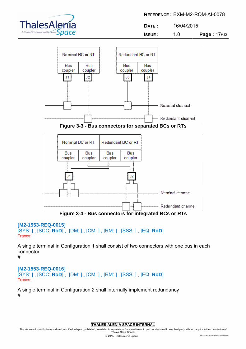
[M2-1553-REQ-0010] [SYS: ] , [SCC: ] , [DM: ] , [CM: ] , [RM: ] , [SSS: ] , [EQ: RoD] Traces: The characteristics of a bus terminal shall be in conformance with [LR 0001] § 4.5.2 and 30.10.6. # [M2-1553-REQ-0011] [SYS: ] , [SCC: RoD] , [DM: ] , [CM: ] , [RM: ] , [SSS: ] , [EQ: ] Traces: The electrical isolation between buses shall be in conformance with [LR 0001] § 4.6.1. # [M2-1553-REQ-0013] [SYS: ] , [SCC: ] , [DM: ] , [CM: ] , [RM: ] , [SSS: ] , [EQ: RoD] Traces: The stub routing within a terminal shall be in conformance with [LR 0001] § 4.6.2 # [M2-1553-REQ-0014] [SYS: ] , [SCC: RoD] , [DM: ] , [CM: ] , [RM: ] , [SSS: ] , [EQ: RoD] Traces: Two possibilities are available for redundant terminal connection to the buses: 1) Bus connectors for separated BCs or RTs (Figure 3-3) 2) Bus connectors for integrated BCs or RTs (Figure 4-2) #
REFERENCE : DATE :
EXM-M2-RQM-AI-0078 16/04/2015
ISSUE : 1.0 Page : 17/63
THALES ALENIA SPACE INTERNAL
This document is not to be reproduced, modified, adapted, published, translated in any material form in whole or in part nor disclosed to any third party without the prior written permission of Thales Alenia Space.
2015, Thales Alenia Space Template 83230326-DOC-TAS-EN/002
Figure 3-3 - Bus connectors for separated BCs or RTs
Figure 3-4 - Bus connectors for integrated BCs or RTs
[M2-1553-REQ-0015] [SYS: ] , [SCC: RoD] , [DM: ] , [CM: ] , [RM: ] , [SSS: ] , [EQ: RoD] Traces: A single terminal in Configuration 1 shall consist of two connectors with one bus in each connector # [M2-1553-REQ-0016] [SYS: ] , [SCC: RoD] , [DM: ] , [CM: ] , [RM: ] , [SSS: ] , [EQ: RoD] Traces: A single terminal in Configuration 2 shall internally implement redundancy #
REFERENCE : DATE :
EXM-M2-RQM-AI-0078 16/04/2015
ISSUE : 1.0 Page : 18/63
THALES ALENIA SPACE INTERNAL
This document is not to be reproduced, modified, adapted, published, translated in any material form in whole or in part nor disclosed to any third party without the prior written permission of Thales Alenia Space.
2015, Thales Alenia Space Template 83230326-DOC-TAS-EN/002
[M2-1553-REQ-0017] [SYS: ] , [SCC: RoD] , [DM: ] , [CM: ] , [RM: ] , [SSS: ] , [EQ: RoD] Traces: A single terminal in Configuration 2 shall consist of two connectors with two stubs belonging to one bus in each connector # [M2-1553-REQ-0018] [SYS: ] , [SCC: ] , [DM: ] , [CM: ] , [RM: ] , [SSS: ] , [EQ: RoD] Traces: Configuration 1 (i.e. Bus connectors for separated BCs or RTs) shall be used by units having a modular design where for instance nominal and redundant terminals are located on different modules with some physical separation # [M2-1553-REQ-0019] [SYS: ] , [SCC: ] , [DM: ] , [CM: ] , [RM: ] , [SSS: ] , [EQ: RoD] Traces: Configuration 2 (i.e. Bus connectors for integrated BCs or RTs) shall be used by units where for instance nominal and redundant terminals are located on the same physical module with almost no physical separation # [M2-1553-REQ-0181] [SYS: ] , [SCC: ] , [DM: ] , [CM: ] , [RM: ] , [SSS: ] , [EQ: ] Traces: Terminal power on/off noise shall be compliant with [LR 0001] § 30.10.6. #
3.4 Data Link Layer
3.4.1 General Requirements
[M2-1553-REQ-0020] [SYS: ] , [SCC: ] , [DM: ] , [CM: ] , [RM: ] , [SSS: ] , [EQ: RoD] Traces: The 1553B Bus Controller (BC) and Remote Terminals (RT) interfaces shall be implemented according to the MIL-Std-1553B standard [LR 0001] #

REFERENCE : DATE :
EXM-M2-RQM-AI-0078 16/04/2015
ISSUE : 1.0 Page : 19/63
THALES ALENIA SPACE INTERNAL
This document is not to be reproduced, modified, adapted, published, translated in any material form in whole or in part nor disclosed to any third party without the prior written permission of Thales Alenia Space.
2015, Thales Alenia Space Template 83230326-DOC-TAS-EN/002
[M2-1553-REQ-0021] [SYS: ] , [SCC: RoD, T] , [DM: ] , [CM: ] , [RM: ] , [SSS: ] , [EQ: RoD, T] Traces: The 1553B BUS RT shall be auto-initialised following Power-on Reset or Warm Reset allowing the AVS BC to communicate with the RT over either SCC MIL-1553 A or SCC MIL-1553 B line. #
REFERENCE : DATE :
EXM-M2-RQM-AI-0078 16/04/2015
ISSUE : 1.0 Page : 20/63
THALES ALENIA SPACE INTERNAL
This document is not to be reproduced, modified, adapted, published, translated in any material form in whole or in part nor disclosed to any third party without the prior written permission of Thales Alenia Space.
2015, Thales Alenia Space Template 83230326-DOC-TAS-EN/002
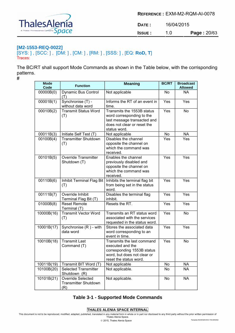
[M2-1553-REQ-0022] [SYS: ] , [SCC: ] , [DM: ] , [CM: ] , [RM: ] , [SSS: ] , [EQ: RoD, T] Traces: The BC/RT shall support Mode Commands as shown in the Table below, with the corrisponding patterns. #
Mode Code Function
Meaning BC/RT Broadcast Allowed
00000B(0) Dynamic Bus Control (T)
Not applicable No NA
00001B(1) Synchronise (T) - without data word
Informs the RT of an event in time.
Yes Yes
00010B(2) Transmit Status Word (T)
Transmits the 1553B status word corresponding to the last message transacted and does not clear or reset the status word.
Yes No
00011B(3) Initiate Self Test (T) Not applicable No NA 00100B(4) Transmitter Shutdown
(T) Disables the channel opposite the channel on which the command was received.
Yes Yes
00101B(5) Override Transmitter Shutdown (T)
Enables the channel previously disabled and opposite the channel on which the command was received.
Yes Yes
00110B(6) Inhibit Terminal Flag Bit (T)
Inhibits the terminal flag bit from being set in the status word.
Yes Yes
00111B(7) Override Inhibit Terminal Flag Bit (T)
Disables the terminal flag inhibit.
Yes Yes
01000B(8) Reset Remote Terminal (T)
Resets the RT. Yes Yes
10000B(16) Transmit Vector Word (T)
Transmits an RT status word associated with the services requested in the status word.
Yes No
10001B(17) Synchronise (R ) - with data word
Stores the associated data word corresponding to an event in time.
Yes Yes
10010B(18) Transmit Last Command (T)
Transmits the last command executed and the corresponding 1553B status word, but does not clear or reset the status word.
Yes No
10011B(19) Transmit BIT Word (T) Not applicable No NA 10100B(20) Selected Transmitter
Shutdown (R) Not applicable. No NA
10101B(21) Override Selected Transmitter Shutdown (R)
Not applicable. No NA
Table 3-1 - Supported Mode Commands
REFERENCE : DATE :
EXM-M2-RQM-AI-0078 16/04/2015
ISSUE : 1.0 Page : 21/63
THALES ALENIA SPACE INTERNAL
This document is not to be reproduced, modified, adapted, published, translated in any material form in whole or in part nor disclosed to any third party without the prior written permission of Thales Alenia Space.
2015, Thales Alenia Space Template 83230326-DOC-TAS-EN/002
[M2-1553-REQ-0023] [SYS: ] , [SCC: ] , [DM: ] , [CM: ] , [RM: ] , [SSS: ] , [EQ: RoD, T] Traces: The Synchronise (without data word) Mode Command shall meet the requirements specified in [LR 0001] §4.3.3.5.1.7.2 NOTE: The Synchronise mode command informs the RT/subsystem of an event time to allow coordination between the BC and receiving terminals. At present, no functional use has been identified. # [M2-1553-REQ-0024] [SYS: ] , [SCC: ] , [DM: ] , [CM: ] , [RM: ] , [SSS: ] , [EQ: RoD, T] Traces: The Transmit Status Word Mode Command shall meet the requirements specified in [LR 0001] §4.3.3.5.1.7.3 NOTE: The transmit status word mode command causes the RT to transmit the status word associated with the last valid command word. The mode command does not alter the state of the status word. # [M2-1553-REQ-0025] [SYS: ] , [SCC: ] , [DM: ] , [CM: ] , [RM: ] , [SSS: ] , [EQ: RoD, T] Traces: The Transmitter Shutdown Mode Command shall meet the requirements specified in [LR 0001] §4.3.3.5.1.7.5 NOTE: The transmitter shutdown mode command causes the RT to disable the transmitter associated with the redundant bus. That is, disables 1553 Bus B transmitter if mode command is received on the 1553 Bus A, and vice versa. It is not possible, as per [LR 0001], to shut down a transmitter on the bus from which the mode command is received. The transmitter shutdown command would be used to disable a "jabbering" transmitter. A broadcast mode command would be used if the faulty transmitter is not easily identifiable. Note that, from [LR 0001] requirement, an RT must include an hardware implemented time-out to preclude a signal transmission of greater than 800 ms (TBC). #

REFERENCE : DATE :
EXM-M2-RQM-AI-0078 16/04/2015
ISSUE : 1.0 Page : 22/63
THALES ALENIA SPACE INTERNAL
This document is not to be reproduced, modified, adapted, published, translated in any material form in whole or in part nor disclosed to any third party without the prior written permission of Thales Alenia Space.
2015, Thales Alenia Space Template 83230326-DOC-TAS-EN/002
[M2-1553-REQ-0026] [SYS: ] , [SCC: ] , [DM: ] , [CM: ] , [RM: ] , [SSS: ] , [EQ: RoD, T] Traces: The Override Transmitter Shutdown Mode Command shall meet the requirements specified in [LR 0001] §4.3.3.5.1.7.6 NOTE: The override transmitter shutdown mode command causes the RT to enable the transmitter associated with the redundant bus. That is, enables 1553 Bus B transmitter if mode command is received on the 1553 Bus A, and vice versa. # [M2-1553-REQ-0027] [SYS: ] , [SCC: ] , [DM: ] , [CM: ] , [RM: ] , [SSS: ] , [EQ: RoD, T] Traces: The Inhibit Terminal Flag Bit Mode Command shall meet the requirements specified in [LR 0001] §4.3.3.5.1.7.7 NOTE: The inhibit terminal flag mode command sets the terminal flag bit in all transmissions of the status word to 0 (the unfailed state) condition regardless of the actual state of the terminal flag. # [M2-1553-REQ-0028] [SYS: ] , [SCC: ] , [DM: ] , [CM: ] , [RM: ] , [SSS: ] , [EQ: RoD, T] Traces: The Override Inhibit Terminal Flag Bit Mode Command shall meet the requirements specified in [LR 0001] §4.3.3.5.1.7.8 NOTE: The override inhibit terminal flag bit mode command returns the operation of the terminal to normal. # [M2-1553-REQ-0029] [SYS: ] , [SCC: ] , [DM: ] , [CM: ] , [RM: ] , [SSS: ] , [EQ: RoD, T] Traces: The Reset Remote Terminal Mode Command shall meet the requirements specified in [LR 0001] §4.3.3.5.1.7.9 NOTE: The Reset Remote Terminal command must cause the RT to reset to its initial power-up initialised state as per [LR 0001]. The RT must be able to receive commands after the reset. #
REFERENCE : DATE :
EXM-M2-RQM-AI-0078 16/04/2015
ISSUE : 1.0 Page : 23/63
THALES ALENIA SPACE INTERNAL
This document is not to be reproduced, modified, adapted, published, translated in any material form in whole or in part nor disclosed to any third party without the prior written permission of Thales Alenia Space.
2015, Thales Alenia Space Template 83230326-DOC-TAS-EN/002
[M2-1553-REQ-0030] [SYS: ] , [SCC: ] , [DM: ] , [CM: ] , [RM: ] , [SSS: ] , [EQ: RoD, T] Traces: The Transmit Vector Word Mode Command shall meet the requirements specified in [LR 0001] §4.3.3.5.1.7.11 NOTE: The transmit vector word mode code could be associated with the service request bit in the status word or the vector word could be used to poll the status or to determine the specific service being required by the AVS S/S. Hence the AVS could poll the vector word on a regular basis or acquire the vector word only when the service request bit is set. # [M2-1553-REQ-0031] [SYS: ] , [SCC: ] , [DM: ] , [CM: ] , [RM: ] , [SSS: ] , [EQ: RoD] Traces: The Vector Word shall be used to define the conditions that caused the Service Request bit in the status word to be set and/or Boot mode status. # [M2-1553-REQ-0032] [SYS: ] , [SCC: ] , [DM: ] , [CM: ] , [RM: ] , [SSS: ] , [EQ: RoD, T] Traces: The Synchronise with Data Word Mode (Mode Code 17), command shall meet the requirements specified in [LR 0001] §4.3.3.5.1.7.12 # [M2-1553-REQ-0033] [SYS: ] , [SCC: RoD, T] , [DM: ] , [CM: ] , [RM: ] , [SSS: ] , [EQ: ] Traces: Synchronise with Data Word Mode command, broadcast on the S/C Data Bus every 50 ms period, shall allow Users to synchronise to the AVS TS timeline based operations for coordination. The synchronisation messages are shown in Figure 5.1-1. NOTE: The synchronisation messages are transmitted every 50 ms period, referred to as Time Slices (TS) periods which are synchronous to the AVS OBT. The TS are numbers TS-0 to TS-19 where TS-0 is synchronous with the start of a new second of the AVS OBT. #
REFERENCE : DATE :
EXM-M2-RQM-AI-0078 16/04/2015
ISSUE : 1.0 Page : 24/63
THALES ALENIA SPACE INTERNAL
This document is not to be reproduced, modified, adapted, published, translated in any material form in whole or in part nor disclosed to any third party without the prior written permission of Thales Alenia Space.
2015, Thales Alenia Space Template 83230326-DOC-TAS-EN/002
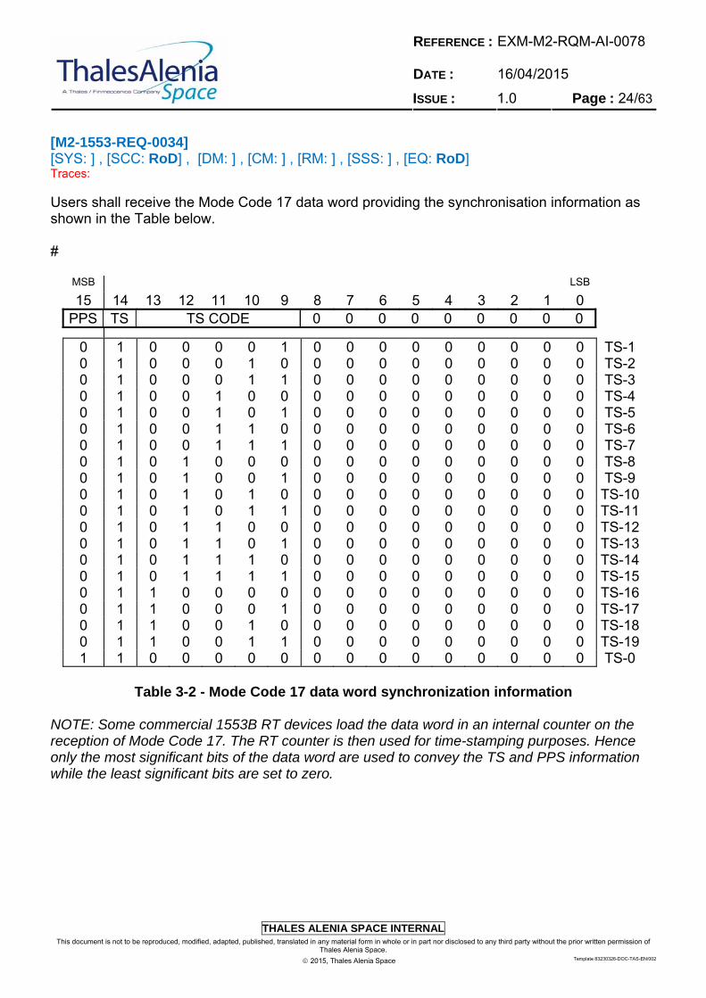
[M2-1553-REQ-0034] [SYS: ] , [SCC: RoD] , [DM: ] , [CM: ] , [RM: ] , [SSS: ] , [EQ: RoD] Traces: Users shall receive the Mode Code 17 data word providing the synchronisation information as shown in the Table below. #
MSB LSB 15 14 13 12 11 10 9 8 7 6 5 4 3 2 1 0
PPS TS TS CODE 0 0 0 0 0 0 0 0 0
0 1 0 0 0 0 1 0 0 0 0 0 0 0 0 0 TS-1 0 1 0 0 0 1 0 0 0 0 0 0 0 0 0 0 TS-2 0 1 0 0 0 1 1 0 0 0 0 0 0 0 0 0 TS-3 0 1 0 0 1 0 0 0 0 0 0 0 0 0 0 0 TS-4 0 1 0 0 1 0 1 0 0 0 0 0 0 0 0 0 TS-5 0 1 0 0 1 1 0 0 0 0 0 0 0 0 0 0 TS-6 0 1 0 0 1 1 1 0 0 0 0 0 0 0 0 0 TS-7 0 1 0 1 0 0 0 0 0 0 0 0 0 0 0 0 TS-8 0 1 0 1 0 0 1 0 0 0 0 0 0 0 0 0 TS-9 0 1 0 1 0 1 0 0 0 0 0 0 0 0 0 0 TS-100 1 0 1 0 1 1 0 0 0 0 0 0 0 0 0 TS-110 1 0 1 1 0 0 0 0 0 0 0 0 0 0 0 TS-120 1 0 1 1 0 1 0 0 0 0 0 0 0 0 0 TS-130 1 0 1 1 1 0 0 0 0 0 0 0 0 0 0 TS-140 1 0 1 1 1 1 0 0 0 0 0 0 0 0 0 TS-150 1 1 0 0 0 0 0 0 0 0 0 0 0 0 0 TS-160 1 1 0 0 0 1 0 0 0 0 0 0 0 0 0 TS-170 1 1 0 0 1 0 0 0 0 0 0 0 0 0 0 TS-180 1 1 0 0 1 1 0 0 0 0 0 0 0 0 0 TS-191 1 0 0 0 0 0 0 0 0 0 0 0 0 0 0 TS-0
Table 3-2 - Mode Code 17 data word synchronization information
NOTE: Some commercial 1553B RT devices load the data word in an internal counter on the reception of Mode Code 17. The RT counter is then used for time-stamping purposes. Hence only the most significant bits of the data word are used to convey the TS and PPS information while the least significant bits are set to zero.
REFERENCE : DATE :
EXM-M2-RQM-AI-0078 16/04/2015
ISSUE : 1.0 Page : 25/63
THALES ALENIA SPACE INTERNAL
This document is not to be reproduced, modified, adapted, published, translated in any material form in whole or in part nor disclosed to any third party without the prior written permission of Thales Alenia Space.
2015, Thales Alenia Space Template 83230326-DOC-TAS-EN/002
[M2-1553-REQ-0035] [SYS: ] , [SCC: ] , [DM: ] , [CM: ] , [RM: ] , [SSS: ] , [EQ: RoD, T] Traces: Transmit Last Command Word Mode Code shall meet the requirements specified in [LR 0001] §4.3.3.5.1.7.13 NOTE: Transmit last command mode code is used in the error handling and recovery process to determine the last valid command received by the RT, prior to the mode code. The mode code does not change the contents of the last command or status word. An RT receiving this mode command will transmit the previous status word followed by a data word which contains the previous 16-bits of the last valid command word received. # [M2-1553-REQ-0036] [SYS: ] , [SCC: ] , [DM: ] , [CM: ] , [RM: ] , [SSS: ] , [EQ: RoD] Traces: Services that are not supported, either as Mode Codes or Subaddresses, shall be illegalised. # [M2-1553-REQ-0037] [SYS: ] , [SCC: ] , [DM: ] , [CM: ] , [RM: ] , [SSS: ] , [EQ: RoD, T] Traces: Not supported Mode Code or Sub-address messages transmitted in broadcast shall not generate errors when receiving the message. Also Sub-addresses dedicated to broadcast messages shall not be used for other purposes (i.e. reserved). #
3.4.1.1 Bus Controller (BC) Functions
[M2-1553-REQ-0038] [SYS: ] , [SCC: ] , [DM: ] , [CM: ] , [RM: ] , [SSS: ] , [EQ: RoD] Traces: The ESA-OBC shall act as Bus Controller (BC) on the SCC MIL-1553 bus # [M2-1553-REQ-0039] [SYS: ] , [SCC: ] , [DM: ] , [CM: ] , [RM: ] , [SSS: ] , [EQ: RoD] Traces: Automated message repetition by the BC in case of transmission errors shall not be used. (TBC) #

REFERENCE : DATE :
EXM-M2-RQM-AI-0078 16/04/2015
ISSUE : 1.0 Page : 26/63
THALES ALENIA SPACE INTERNAL
This document is not to be reproduced, modified, adapted, published, translated in any material form in whole or in part nor disclosed to any third party without the prior written permission of Thales Alenia Space.
2015, Thales Alenia Space Template 83230326-DOC-TAS-EN/002
[M2-1553-REQ-0040] [SYS: ] , [SCC: ] , [DM: ] , [CM: ] , [RM: ] , [SSS: ] , [EQ: RoD] Traces: BC shall systematically set to zero all generated fields indicated as "Reserved Bits" in the present specification. # [M2-1553-REQ-0041] [SYS: ] , [SCC: ] , [DM: ] , [CM: ] , [RM: ] , [SSS: ] , [EQ: RoD, T] Traces: BC shall correctly function even if any of the received fields indicated as "Reserved Bits" in the present specification contains other values than zero. # [M2-1553-REQ-0042] [SYS: ] , [SCC: ] , [DM: ] , [CM: ] , [RM: ] , [SSS: ] , [EQ: RoD] Traces: Broadcast messages shall be supported. # [M2-1553-REQ-0043] [SYS: ] , [SCC: ] , [DM: ] , [CM: ] , [RM: ] , [SSS: ] , [EQ: RoD, T] Traces: The BC shall be able to send MIL-Bus messages to the units or instruments working as RTs on the bus according to a Send List provided by Transfer Layer for each Communication Frame. Note: Send list are intended as a list of messages to be scheduled in sequence or according to a given time delay inside a Communication Frame. # [M2-1553-REQ-0044] [SYS: ] , [SCC: ] , [DM: ] , [CM: ] , [RM: ] , [SSS: ] , [EQ: RoD, T] Traces: The BC shall support the run-time update of a Send List to be executed in a CF up to the end of previous CF. # [M2-1553-REQ-0045] [SYS: ] , [SCC: ] , [DM: ] , [CM: ] , [RM: ] , [SSS: ] , [EQ: RoD, T] Traces: The BC shall notify to Transfer Layer the completion of execution of a Send list. #
REFERENCE : DATE :
EXM-M2-RQM-AI-0078 16/04/2015
ISSUE : 1.0 Page : 27/63
THALES ALENIA SPACE INTERNAL
This document is not to be reproduced, modified, adapted, published, translated in any material form in whole or in part nor disclosed to any third party without the prior written permission of Thales Alenia Space.
2015, Thales Alenia Space Template 83230326-DOC-TAS-EN/002
[M2-1553-REQ-0046] [SYS: ] , [SCC: ] , [DM: ] , [CM: ] , [RM: ] , [SSS: ] , [EQ: RoD] Traces: The BC shall support the RT SA allocation as shown in table 5-3: SA utilization table. # [M2-1553-REQ-0047] [SYS: ] , [SCC: ] , [DM: ] , [CM: ] , [RM: ] , [SSS: ] , [EQ: RoD, T] Traces: The BC shall make available to ESA-OBC ASW all response data gathered from RTs. # [M2-1553-REQ-0048] [SYS: ] , [SCC: ] , [DM: ] , [CM: ] , [RM: ] , [SSS: ] , [EQ: RoD, T] Traces: The BC shall read from ESA-OBC ASW the data to be transfered to RTs. #
3.4.1.2 Remote Terminal Functions
[M2-1553-REQ-0049] [SYS: ] , [SCC: RoD] , [DM: ] , [CM: ] , [RM: ] , [SSS: ] , [EQ: RoD] Traces: All spacecraft units or instruments connected to the data bus shall act as Remote Terminals (RT). # [M2-1553-REQ-0050] [SYS: ] , [SCC: ] , [DM: ] , [CM: ] , [RM: ] , [SSS: ] , [EQ: RoD] Traces: RT shall systematically set to zero all generated fields indicated as "Reserved Bits" in the present specification. # [M2-1553-REQ-0051] [SYS: ] , [SCC: ] , [DM: ] , [CM: ] , [RM: ] , [SSS: ] , [EQ: RoD, T] Traces: Each RT shall correctly function even if any of the received fields indicated as "Reserved Bits" in the present specification contains other values than zero. #
REFERENCE : DATE :
EXM-M2-RQM-AI-0078 16/04/2015
ISSUE : 1.0 Page : 28/63
THALES ALENIA SPACE INTERNAL
This document is not to be reproduced, modified, adapted, published, translated in any material form in whole or in part nor disclosed to any third party without the prior written permission of Thales Alenia Space.
2015, Thales Alenia Space Template 83230326-DOC-TAS-EN/002
[M2-1553-REQ-0052] [SYS: ] , [SCC: ] , [DM: ] , [CM: ] , [RM: ] , [SSS: ] , [EQ: RoD, T] Traces: The RT shall support broadcast messages. # [M2-1553-REQ-0053] [SYS: ] , [SCC: RoD] , [DM: ] , [CM: ] , [RM: ] , [SSS: ] , [EQ: RoD] Traces: RT to RT transmissions shall not be used. #
3.4.1.3 Message Format and Word Formats
3.4.1.3.1 Word Formats
[M2-1553-REQ-0054] [SYS: ] , [SCC: RoD] , [DM: ] , [CM: ] , [RM: ] , [SSS: ] , [EQ: ] Traces: The data bus word format shall comply with [LR 0001] §4.3.3.5. # [M2-1553-REQ-0055] [SYS: ] , [SCC: RoD] , [DM: ] , [CM: ] , [RM: ] , [SSS: ] , [EQ: RoD] Traces: The data bus word shall use a Sync preamble as defined in [LR 0001] §4.3.3.5.1.1. # [M2-1553-REQ-0056] [SYS: ] , [SCC: RoD] , [DM: ] , [CM: ] , [RM: ] , [SSS: ] , [EQ: RoD] Traces: Command and Data word on the data bus word shall use a parity bit as defined in [LR 0001] §4.3.3.5.1.6. #
REFERENCE : DATE :
EXM-M2-RQM-AI-0078 16/04/2015
ISSUE : 1.0 Page : 29/63
THALES ALENIA SPACE INTERNAL
This document is not to be reproduced, modified, adapted, published, translated in any material form in whole or in part nor disclosed to any third party without the prior written permission of Thales Alenia Space.
2015, Thales Alenia Space Template 83230326-DOC-TAS-EN/002
3.4.1.3.2 Message Formats
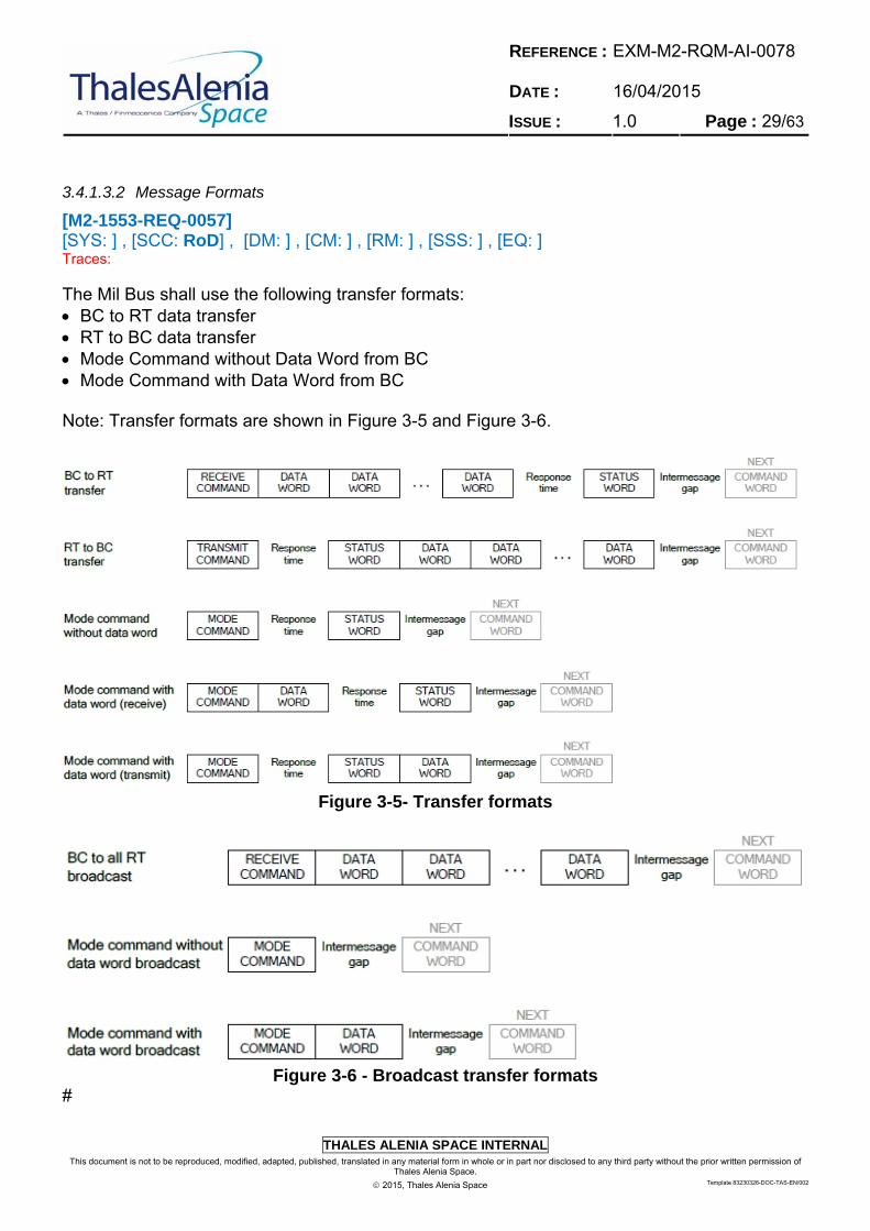
[M2-1553-REQ-0057] [SYS: ] , [SCC: RoD] , [DM: ] , [CM: ] , [RM: ] , [SSS: ] , [EQ: ] Traces: The Mil Bus shall use the following transfer formats: BC to RT data transfer RT to BC data transfer Mode Command without Data Word from BC Mode Command with Data Word from BC Note: Transfer formats are shown in Figure 3-5 and Figure 3-6.
Figure 3-5- Transfer formats
Figure 3-6 - Broadcast transfer formats
#
REFERENCE : DATE :
EXM-M2-RQM-AI-0078 16/04/2015
ISSUE : 1.0 Page : 30/63
THALES ALENIA SPACE INTERNAL
This document is not to be reproduced, modified, adapted, published, translated in any material form in whole or in part nor disclosed to any third party without the prior written permission of Thales Alenia Space.
2015, Thales Alenia Space Template 83230326-DOC-TAS-EN/002
[M2-1553-REQ-0058] [SYS: ] , [SCC: RoD] , [DM: ] , [CM: ] , [RM: ] , [SSS: ] , [EQ: RoD, T] Traces: Receive Messages shall be sent from the BC to the addressed RT, which responds with dedicated actions. There shall always be a Status Word reply but no Data reply. # [M2-1553-REQ-0059] [SYS: ] , [SCC: ] , [DM: ] , [CM: ] , [RM: ] , [SSS: ] , [EQ: RoD, T] Traces: Transmit Messages shall be sent from the addressed RT; they carry a Status Word plus the requested data. # [M2-1553-REQ-0060] [SYS: ] , [SCC: ] , [DM: ] , [CM: ] , [RM: ] , [SSS: ] , [EQ: RoD, T] Traces: Broadcast Messages shall be used by the BC to send Commands (with or without data) to all RTs in parallel, which initiate dedicated actions at the RTs (e.g. synchronization). There is no status or data reply allowed. # [M2-1553-REQ-0061] [SYS: ] , [SCC: ] , [DM: ] , [CM: ] , [RM: ] , [SSS: ] , [EQ: RoD, T] Traces: A RT shall avoid answering to a Broadcast Messages with status or data word. #
3.4.1.4 Message Timing
[M2-1553-REQ-0062] [SYS: ] , [SCC: ] , [DM: ] , [CM: ] , [RM: ] , [SSS: ] , [EQ: RoD] Traces: The timing of messages shall be in accordance to [LR 0001]. # [M2-1553-REQ-0063] [SYS: ] , [SCC: ] , [DM: ] , [CM: ] , [RM: ] , [SSS: ] , [EQ: RoD, T] Traces:
Each RT shall respond to a valid command word within the time period 4.0 to 12.0 s, as per [LR 0001] §4.3.3.8. #
REFERENCE : DATE :
EXM-M2-RQM-AI-0078 16/04/2015
ISSUE : 1.0 Page : 31/63
THALES ALENIA SPACE INTERNAL
This document is not to be reproduced, modified, adapted, published, translated in any material form in whole or in part nor disclosed to any third party without the prior written permission of Thales Alenia Space.
2015, Thales Alenia Space Template 83230326-DOC-TAS-EN/002
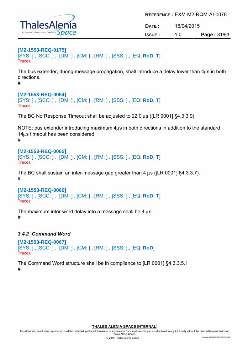
[M2-1553-REQ-0175] [SYS: ] , [SCC: ] , [DM: ] , [CM: ] , [RM: ] , [SSS: ] , [EQ: RoD, T] Traces:
The bus extender, during message propagation, shall introduce a delay lower than 4s in both directions. # [M2-1553-REQ-0064] [SYS: ] , [SCC: ] , [DM: ] , [CM: ] , [RM: ] , [SSS: ] , [EQ: RoD, T] Traces:
The BC No Response Timeout shall be adjusted to 22.0 s ([LR 0001] §4.3.3.9). NOTE: bus extender introducing maximum 4s in both directions in addition to the standard 14s timeout has been considered. # [M2-1553-REQ-0065] [SYS: ] , [SCC: ] , [DM: ] , [CM: ] , [RM: ] , [SSS: ] , [EQ: RoD, T] Traces:
The BC shall sustain an inter-message gap greater than 4 s ([LR 0001] §4.3.3.7). # [M2-1553-REQ-0066] [SYS: ] , [SCC: ] , [DM: ] , [CM: ] , [RM: ] , [SSS: ] , [EQ: RoD, T] Traces:
The maximum inter-word delay into a message shall be 4 s. #
3.4.2 Command Word
[M2-1553-REQ-0067] [SYS: ] , [SCC: ] , [DM: ] , [CM: ] , [RM: ] , [SSS: ] , [EQ: RoD] Traces: The Command Word structure shall be in compliance to [LR 0001] §4.3.3.5.1 #
REFERENCE : DATE :
EXM-M2-RQM-AI-0078 16/04/2015
ISSUE : 1.0 Page : 32/63
THALES ALENIA SPACE INTERNAL
This document is not to be reproduced, modified, adapted, published, translated in any material form in whole or in part nor disclosed to any third party without the prior written permission of Thales Alenia Space.
2015, Thales Alenia Space Template 83230326-DOC-TAS-EN/002
3.4.2.1 RT Address Field
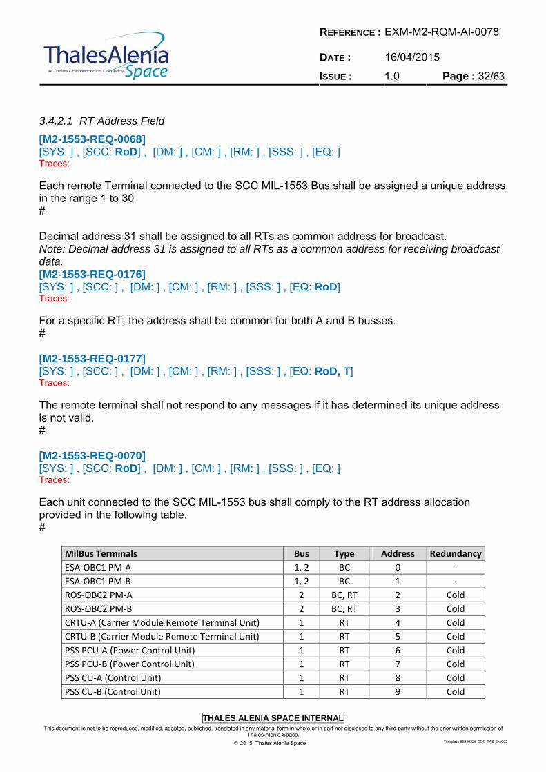
[M2-1553-REQ-0068] [SYS: ] , [SCC: RoD] , [DM: ] , [CM: ] , [RM: ] , [SSS: ] , [EQ: ] Traces: Each remote Terminal connected to the SCC MIL-1553 Bus shall be assigned a unique address in the range 1 to 30 # Decimal address 31 shall be assigned to all RTs as common address for broadcast. Note: Decimal address 31 is assigned to all RTs as a common address for receiving broadcast data. [M2-1553-REQ-0176] [SYS: ] , [SCC: ] , [DM: ] , [CM: ] , [RM: ] , [SSS: ] , [EQ: RoD] Traces: For a specific RT, the address shall be common for both A and B busses. # [M2-1553-REQ-0177] [SYS: ] , [SCC: ] , [DM: ] , [CM: ] , [RM: ] , [SSS: ] , [EQ: RoD, T] Traces: The remote terminal shall not respond to any messages if it has determined its unique address is not valid. # [M2-1553-REQ-0070] [SYS: ] , [SCC: RoD] , [DM: ] , [CM: ] , [RM: ] , [SSS: ] , [EQ: ] Traces: Each unit connected to the SCC MIL-1553 bus shall comply to the RT address allocation provided in the following table. #
MilBus Terminals Bus Type Address Redundancy
ESA‐OBC1 PM‐A 1, 2 BC 0 ‐
ESA‐OBC1 PM‐B 1, 2 BC 1 ‐
ROS‐OBC2 PM‐A 2 BC, RT 2 Cold
ROS‐OBC2 PM‐B 2 BC, RT 3 Cold
CRTU‐A (Carrier Module Remote Terminal Unit) 1 RT 4 Cold
CRTU‐B (Carrier Module Remote Terminal Unit) 1 RT 5 Cold
PSS PCU‐A (Power Control Unit) 1 RT 6 Cold
PSS PCU‐B (Power Control Unit) 1 RT 7 Cold
PSS CU‐A (Control Unit) 1 RT 8 Cold
PSS CU‐B (Control Unit) 1 RT 9 Cold
REFERENCE : DATE :
EXM-M2-RQM-AI-0078 16/04/2015
ISSUE : 1.0 Page : 33/63
THALES ALENIA SPACE INTERNAL
This document is not to be reproduced, modified, adapted, published, translated in any material form in whole or in part nor disclosed to any third party without the prior written permission of Thales Alenia Space.
2015, Thales Alenia Space Template 83230326-DOC-TAS-EN/002
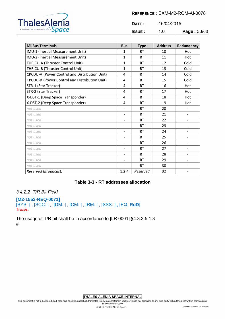
MilBus Terminals Bus Type Address Redundancy
IMU‐1 (Inertial Measurement Unit) 1 RT 10 Hot
IMU‐2 (Inertial Measurement Unit) 1 RT 11 Hot
THR CU‐A (Thruster Control Unit) 1 RT 12 Cold
THR CU‐B (Thruster Control Unit) 1 RT 13 Cold
CPCDU‐A (Power Control and Distribution Unit) 4 RT 14 Cold
CPCDU‐B (Power Control and Distribution Unit) 4 RT 15 Cold
STR‐1 (Star Tracker) 4 RT 16 Hot
STR‐2 (Star Tracker) 4 RT 17 Hot
X‐DST‐1 (Deep Space Transponder) 4 RT 18 Hot
X‐DST‐2 (Deep Space Transponder) 4 RT 19 Hot
not used ‐ RT 20 ‐
not used ‐ RT 21 ‐
not used ‐ RT 22 ‐
not used ‐ RT 23 ‐
not used ‐ RT 24 ‐
not used ‐ RT 25 ‐
not used ‐ RT 26 ‐
not used ‐ RT 27 ‐
not used ‐ RT 28 ‐
not used ‐ RT 29 ‐
not used ‐ RT 30 ‐
Reserved (Broadcast) 1,2,4 Reserved 31 ‐
Table 3-3 - RT addresses allocation
3.4.2.2 T/R Bit Field
[M2-1553-REQ-0071] [SYS: ] , [SCC: ] , [DM: ] , [CM: ] , [RM: ] , [SSS: ] , [EQ: RoD] Traces: The usage of T/R bit shall be in accordance to [LR 0001] §4.3.3.5.1.3 #
REFERENCE : DATE :
EXM-M2-RQM-AI-0078 16/04/2015
ISSUE : 1.0 Page : 34/63
THALES ALENIA SPACE INTERNAL
This document is not to be reproduced, modified, adapted, published, translated in any material form in whole or in part nor disclosed to any third party without the prior written permission of Thales Alenia Space.
2015, Thales Alenia Space Template 83230326-DOC-TAS-EN/002
3.4.2.3 Subaddress/Mode Field
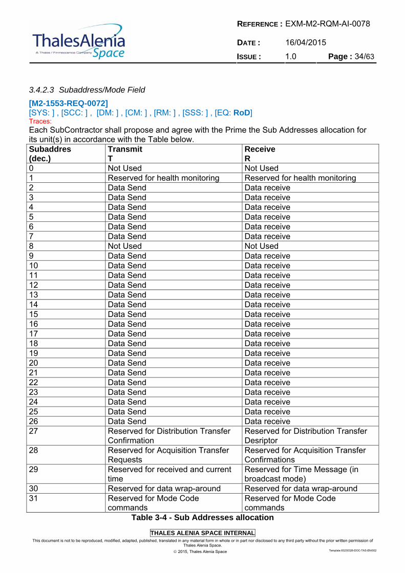
[M2-1553-REQ-0072] [SYS: ] , [SCC: ] , [DM: ] , [CM: ] , [RM: ] , [SSS: ] , [EQ: RoD] Traces: Each SubContractor shall propose and agree with the Prime the Sub Addresses allocation for its unit(s) in accordance with the Table below. Subaddres (dec.)
Transmit T
Receive R
0 Not Used Not Used 1 Reserved for health monitoring Reserved for health monitoring 2 Data Send Data receive 3 Data Send Data receive 4 Data Send Data receive 5 Data Send Data receive 6 Data Send Data receive 7 Data Send Data receive 8 Not Used Not Used 9 Data Send Data receive 10 Data Send Data receive 11 Data Send Data receive 12 Data Send Data receive 13 Data Send Data receive 14 Data Send Data receive 15 Data Send Data receive 16 Data Send Data receive 17 Data Send Data receive 18 Data Send Data receive 19 Data Send Data receive 20 Data Send Data receive 21 Data Send Data receive 22 Data Send Data receive 23 Data Send Data receive 24 Data Send Data receive 25 Data Send Data receive 26 Data Send Data receive 27 Reserved for Distribution Transfer
Confirmation Reserved for Distribution Transfer Desriptor
28 Reserved for Acquisition Transfer Requests
Reserved for Acquisition Transfer Confirmations
29 Reserved for received and current time
Reserved for Time Message (in broadcast mode)
30 Reserved for data wrap-around Reserved for data wrap-around 31 Reserved for Mode Code
commands Reserved for Mode Code commands
Table 3-4 - Sub Addresses allocation
REFERENCE : DATE :
EXM-M2-RQM-AI-0078 16/04/2015
ISSUE : 1.0 Page : 35/63
THALES ALENIA SPACE INTERNAL
This document is not to be reproduced, modified, adapted, published, translated in any material form in whole or in part nor disclosed to any third party without the prior written permission of Thales Alenia Space.
2015, Thales Alenia Space Template 83230326-DOC-TAS-EN/002
[M2-1553-REQ-0073] [SYS: ] , [SCC: ] , [DM: ] , [CM: ] , [RM: ] , [SSS: ] , [EQ: RoD] Traces: For Subaddresses differnet from decimal 31, the Data Word Count Field (command Word bits 11 to 15) shall indicate the quantity of data words to be either sent out or received by the RT. It shall be used according to [LR 0001] § 4.3.3.5.1.5. # [M2-1553-REQ-0074] [SYS: ] , [SCC: ] , [DM: ] , [CM: ] , [RM: ] , [SSS: ] , [EQ: RoD] Traces: RT shall reserve SA 30 data wrap around function as defined [LR 0001] §30.7. # [M2-1553-REQ-0075] [SYS: ] , [SCC: ] , [DM: ] , [CM: ] , [RM: ] , [SSS: ] , [EQ: RoD] Traces: The use of Subaddress 31 ('11111' bin) shall indicate that the bits 11 to 15 of the Command Word shall be interpreted as a Mode Code. #
3.4.3 RT Status Word
[M2-1553-REQ-0076] [SYS: ] , [SCC: ] , [DM: ] , [CM: ] , [RM: ] , [SSS: ] , [EQ: RoD] Traces: The Status Word structure shall comply with [LR 0001] §4.3.3.5.3. #
3.4.3.1 Status Word bits
[M2-1553-REQ-0077] [SYS: ] , [SCC: ] , [DM: ] , [CM: ] , [RM: ] , [SSS: ] , [EQ: RoD, T] Traces: After the reception of any MIL Bus message (except a MIL Bus broadcast message), a RT shall respond with a Status Word. #
REFERENCE : DATE :
EXM-M2-RQM-AI-0078 16/04/2015
ISSUE : 1.0 Page : 36/63
THALES ALENIA SPACE INTERNAL
This document is not to be reproduced, modified, adapted, published, translated in any material form in whole or in part nor disclosed to any third party without the prior written permission of Thales Alenia Space.
2015, Thales Alenia Space Template 83230326-DOC-TAS-EN/002
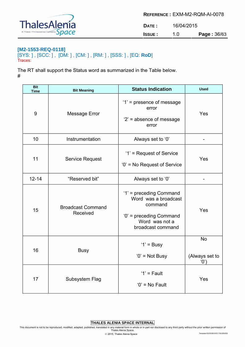
[M2-1553-REQ-0118] [SYS: ] , [SCC: ] , [DM: ] , [CM: ] , [RM: ] , [SSS: ] , [EQ: RoD] Traces: The RT shall support the Status word as summarized in the Table below. #
Bit Time Bit Meaning Status Indication Used
9 Message Error
‘1’ = presence of message
error
‘2’ = absence of message error
Yes
10 Instrumentation Always set to ‘0’ -
11 Service Request
‘1’ = Request of Service
‘0’ = No Request of Service
Yes
12-14 “Reserved bit” Always set to ‘0’ -
15 Broadcast Command
Received
‘1’ = preceding Command
Word was a broadcast command
‘0’ = preceding Command
Word was not a broadcast command
Yes
16 Busy
‘1’ = Busy
‘0’ = Not Busy
No
(Always set to ‘0’)
17 Subsystem Flag
‘1’ = Fault
‘0’ = No Fault
Yes

REFERENCE : DATE :
EXM-M2-RQM-AI-0078 16/04/2015
ISSUE : 1.0 Page : 37/63
THALES ALENIA SPACE INTERNAL
This document is not to be reproduced, modified, adapted, published, translated in any material form in whole or in part nor disclosed to any third party without the prior written permission of Thales Alenia Space.
2015, Thales Alenia Space Template 83230326-DOC-TAS-EN/002
Bit Time Bit Meaning Status Indication Used
18 Dynamic Bus Control
Acceptance -
No
(Always set to ‘0’)
19 Terminal Flag
‘1’ = Fault
‘0’ = No Fault
Yes
Table 3-5 - RT Status Word format
[M2-1553-REQ-0078] [SYS: ] , [SCC: ] , [DM: ] , [CM: ] , [RM: ] , [SSS: ] , [EQ: RoD] Traces: All the used RT Status Word bit shall be used in accordance to [LR 0001] §4.3.3.5.3. #
3.4.4 Data Word
[M2-1553-REQ-0079] [SYS: ] , [SCC: ] , [DM: ] , [CM: ] , [RM: ] , [SSS: ] , [EQ: RoD] Traces: The Data Word structure shall comply with [LR 0001] §4.3.3.5.2. #
3.4.5 Data Link Layer FDIR
3.4.5.1 Management of Bus Errors
[M2-1553-REQ-0080] [SYS: ] , [SCC: RoD] , [DM: ] , [CM: ] , [RM: ] , [SSS: ] , [EQ: ] Traces: Only standards and mandatory features of the [LR 0001] protocol shall be used to support MIL Bus FDIR. #
REFERENCE : DATE :
EXM-M2-RQM-AI-0078 16/04/2015
ISSUE : 1.0 Page : 38/63
THALES ALENIA SPACE INTERNAL
This document is not to be reproduced, modified, adapted, published, translated in any material form in whole or in part nor disclosed to any third party without the prior written permission of Thales Alenia Space.
2015, Thales Alenia Space Template 83230326-DOC-TAS-EN/002
[M2-1553-REQ-0081] [SYS: ] , [SCC: RoD] , [DM: ] , [CM: ] , [RM: ] , [SSS: ] , [EQ: ] Traces: For failure detection the SCC MIL-1553 Bus shall rely on nominal data traffic. # Note: this means that no specific additional data traffic is generated in support to SCC MIL-1553 Bus FDIR [M2-1553-REQ-0082] [SYS: ] , [SCC: ] , [DM: ] , [CM: ] , [RM: ] , [SSS: ] , [EQ: RoD] Traces: The BC shall support an I/F to Transfer Layer FDIR. # [M2-1553-REQ-0083] [SYS: ] , [SCC: ] , [DM: ] , [CM: ] , [RM: ] , [SSS: ] , [EQ: RoD, T] Traces: The following bus FDIR error conditions shall be detected and recorded by the Data Link Layer FDIR in the BC for each RTs: Manchester coding errors (from BC bus I/F) Parity errors (from BC bus I/F) Incorrect word count (from BC bus I/F) RT no response time-out (from BC bus I/F) # Note: The record of the previous listed error is referred to as "MIL Bus Error list". [M2-1553-REQ-0084] [SYS: ] , [SCC: ] , [DM: ] , [CM: ] , [RM: ] , [SSS: ] , [EQ: RoD, T] Traces: The Data Link Layer FDIR shall generate an error report to Transfer Layer FDIR whenever an error belonging to the MIL Bus Error List is detected. # [M2-1553-REQ-0085] [SYS: ] , [SCC: ] , [DM: ] , [CM: ] , [RM: ] , [SSS: ] , [EQ: RoD, T] Traces: The error report shall identify which errors have been detected among the ones from the MIL Bus Error list. #
REFERENCE : DATE :
EXM-M2-RQM-AI-0078 16/04/2015
ISSUE : 1.0 Page : 39/63
THALES ALENIA SPACE INTERNAL
This document is not to be reproduced, modified, adapted, published, translated in any material form in whole or in part nor disclosed to any third party without the prior written permission of Thales Alenia Space.
2015, Thales Alenia Space Template 83230326-DOC-TAS-EN/002
[M2-1553-REQ-0086] [SYS: ] , [SCC: ] , [DM: ] , [CM: ] , [RM: ] , [SSS: ] , [EQ: RoD, T] Traces: The following bus conditions shall be collected by the Data Link Layer FDIR in the BC for each RTs: RT Message Error bit RT Subsystem Flag RT Terminal Flag Note: The aforementioned bits are the ones defined in Table 5.3.1-1 # [M2-1553-REQ-0087] [SYS: ] , [SCC: ] , [DM: ] , [CM: ] , [RM: ] , [SSS: ] , [EQ: RoD] Traces: The Data Link Layer FDIR shall notify to Transfer Layer FDIR is detected whenever one of the following error is detected: RT Message Error bit RT Subsystem Flag RT Terminal Flag # Note: The assertion of these bit will not be flagged as a bus error. (TBC) [M2-1553-REQ-0088] [SYS: ] , [SCC: ] , [DM: ] , [CM: ] , [RM: ] , [SSS: ] , [EQ: RoD] Traces: No automatic bus reconfiguration shall be implemented at data link layer. # [M2-1553-REQ-0089] [SYS: ] , [SCC: ] , [DM: ] , [CM: ] , [RM: ] , [SSS: ] , [EQ: RoD] Traces: The confirmation threshold shall be set, for each RT, larger than the maximum number of consecutive command blocks in a single transaction, in order to avoid asserting RT Failure before checking multiple RT's responsivity (e.g. in case of communication channel failure, in case of RT failure) #
REFERENCE : DATE :
EXM-M2-RQM-AI-0078 16/04/2015
ISSUE : 1.0 Page : 40/63
THALES ALENIA SPACE INTERNAL
This document is not to be reproduced, modified, adapted, published, translated in any material form in whole or in part nor disclosed to any third party without the prior written permission of Thales Alenia Space.
2015, Thales Alenia Space Template 83230326-DOC-TAS-EN/002
3.5 Transfer Layer
3.5.1 General
This section presents an overview of the Mil Bus management policy adopted in the ASW context. [M2-1553-REQ-0090] [SYS: ] , [SCC: RoD] , [DM: ] , [CM: ] , [RM: ] , [SSS: ] , [EQ: ] Traces: The Transfer Layer shall provide non-packet bidirectional data exchange between ESA-OBC ASW and RTs in compliance to the protocol specified in this section. # [M2-1553-REQ-0091] [SYS: ] , [SCC: RoD] , [DM: ] , [CM: ] , [RM: ] , [SSS: ] , [EQ: ] Traces: The Transfer Layer shall provide TM/TC packet bidirectional data exchange between ESA-OBC ASW and RTs in compliance to the protocol specified in this section. # [M2-1553-REQ-0180] [SYS: ] , [SCC: ] , [DM: ] , [CM: ] , [RM: ] , [SSS: ] , [EQ: ] Traces: The BC shall handle the case of concurrent single and data block transfer from several RT providing the highest priority to the single message. Rationale: The single message is used to notify a failure to the Transfer Layer FDIR. #
3.5.2 Time Protocol
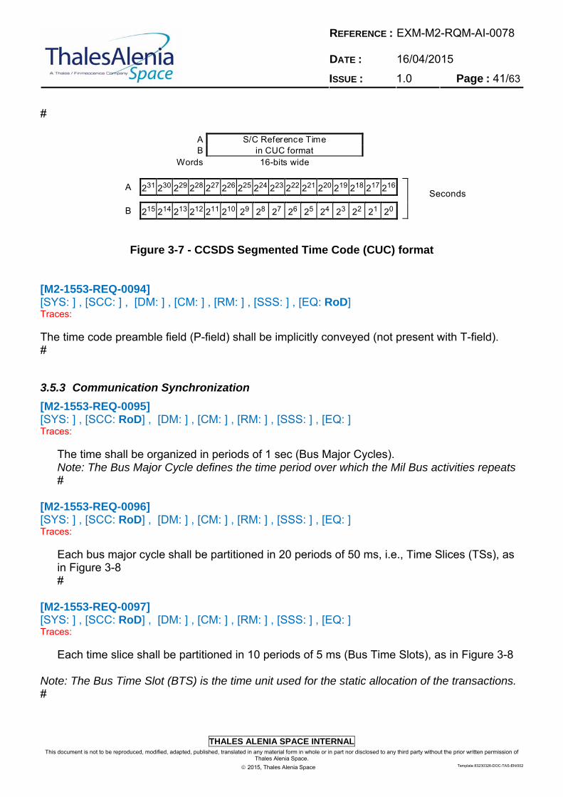
[M2-1553-REQ-0092] [SYS: ] , [SCC: RoD] , [DM: ] , [CM: ] , [RM: ] , [SSS: ] , [EQ: ] Traces: All S/C Data Bus Users not using the Time Distribution service shall allow the service to function correctly without error generation. # [M2-1553-REQ-0093] [SYS: ] , [SCC: ] , [DM: ] , [CM: ] , [RM: ] , [SSS: ] , [EQ: RoD] Traces: The Time Distribution shall be in CCSDS Segmented Time Code (CUC) format as shown in the figure below.
REFERENCE : DATE :
EXM-M2-RQM-AI-0078 16/04/2015
ISSUE : 1.0 Page : 41/63
THALES ALENIA SPACE INTERNAL
This document is not to be reproduced, modified, adapted, published, translated in any material form in whole or in part nor disclosed to any third party without the prior written permission of Thales Alenia Space.
2015, Thales Alenia Space Template 83230326-DOC-TAS-EN/002
#
A B
S/C Reference Time in CUC format
Words 16-bits wide
Figure 3-7 - CCSDS Segmented Time Code (CUC) format
[M2-1553-REQ-0094] [SYS: ] , [SCC: ] , [DM: ] , [CM: ] , [RM: ] , [SSS: ] , [EQ: RoD] Traces: The time code preamble field (P-field) shall be implicitly conveyed (not present with T-field). #
3.5.3 Communication Synchronization
[M2-1553-REQ-0095] [SYS: ] , [SCC: RoD] , [DM: ] , [CM: ] , [RM: ] , [SSS: ] , [EQ: ] Traces:
The time shall be organized in periods of 1 sec (Bus Major Cycles). Note: The Bus Major Cycle defines the time period over which the Mil Bus activities repeats #
[M2-1553-REQ-0096] [SYS: ] , [SCC: RoD] , [DM: ] , [CM: ] , [RM: ] , [SSS: ] , [EQ: ] Traces:
Each bus major cycle shall be partitioned in 20 periods of 50 ms, i.e., Time Slices (TSs), as in Figure 3-8 #
[M2-1553-REQ-0097] [SYS: ] , [SCC: RoD] , [DM: ] , [CM: ] , [RM: ] , [SSS: ] , [EQ: ] Traces:
Each time slice shall be partitioned in 10 periods of 5 ms (Bus Time Slots), as in Figure 3-8
Note: The Bus Time Slot (BTS) is the time unit used for the static allocation of the transactions. #
A 231 230 229 228 227 226 225 224 223 222 221 220 219 218 217 216 Seconds
B 215 214 213 212 211 210 29 28 27 26 25 24 23 22 21 20

REFERENCE : DATE :
EXM-M2-RQM-AI-0078 16/04/2015
ISSUE : 1.0 Page : 42/63
THALES ALENIA SPACE INTERNAL
This document is not to be reproduced, modified, adapted, published, translated in any material form in whole or in part nor disclosed to any third party without the prior written permission of Thales Alenia Space.
2015, Thales Alenia Space Template 83230326-DOC-TAS-EN/002
[M2-1553-REQ-0098] [SYS: ] , [SCC: RoD] , [DM: ] , [CM: ] , [RM: ] , [SSS: ] , [EQ: ] Traces: A set of 32 command blocks shall be associated to each bus time slot. # [M2-1553-REQ-0099] [SYS: ] , [SCC: RoD] , [DM: ] , [CM: ] , [RM: ] , [SSS: ] , [EQ: ] Traces:
A transaction allocated to a bus time slot shall be associated to a set of command blocks. #
[M2-1553-REQ-0100] [SYS: ] , [SCC: RoD] , [DM: ] , [CM: ] , [RM: ] , [SSS: ] , [EQ: ] Traces: Each bus time slot is partitioned in 5 periods of 1 ms (Ticks), as in Figure 3-8.
Note: The tick is the time unit used for the static allocation of the ASW tasks running windows. #
[M2-1553-REQ-0101] [SYS: ] , [SCC: RoD] , [DM: ] , [CM: ] , [RM: ] , [SSS: ] , [EQ: ] Traces: A Logical Transaction allocated into BTS and associated to the RT protocols shall refer to a set of one or more Command Blocks. #
TS 1 ... TS 18 TS 19TS 2
Major Cycle 1s 50ms
TS 0
5ms
BTS 2 ...BTS 1
TIC
K 0
TIC
K 1
TIC
K 2
TIC
K 3
TICK
4
TIC
K 5
TIC
K 6
TIC
K 7
TIC
K 8
TIC
K 9
TIC
K 1
0
TIC
K 1
1
TIC
K 1
2
TIC
K 1
3
TIC
K 1
4
TIC
K 49
TIC
K 15
. . .
BTS 9BTS 0
Figure 3-8 - Bus major Cycle organization
REFERENCE : DATE :
EXM-M2-RQM-AI-0078 16/04/2015
ISSUE : 1.0 Page : 43/63
THALES ALENIA SPACE INTERNAL
This document is not to be reproduced, modified, adapted, published, translated in any material form in whole or in part nor disclosed to any third party without the prior written permission of Thales Alenia Space.
2015, Thales Alenia Space Template 83230326-DOC-TAS-EN/002
[M2-1553-REQ-0103] [SYS: ] , [SCC: ] , [DM: ] , [CM: ] , [RM: ] , [SSS: ] , [EQ: RoD, T] Traces: The BC shall indicate the start of a TS by sending Communication Frame Synchronisation Messages in the format of Synchronise with Data Word mode commands, except when coinciding with the Time Synchronisation Message where this message replaces the Communication Frame Synchronisation Message. # [M2-1553-REQ-0104] [SYS: ] , [SCC: ] , [DM: ] , [CM: ] , [RM: ] , [SSS: ] , [EQ: RoD, T] Traces: The BC shall send the Communication Frame Synchronisation Messages in broadcast mode. #
3.5.4 Set Command Word
[M2-1553-REQ-0105] [SYS: ] , [SCC: ] , [DM: ] , [CM: ] , [RM: ] , [SSS: ] , [EQ: RoD] Traces: When using Set Command Word, the BC shall send any number of data words up to 32 in a single 1553 message. Note: Set Command transactions are limited to only one 1553 message transfer on EXM. Data transfers requiring more than 32 data words should be processed through Data Block Transfer service. # [M2-1553-REQ-0106] [SYS: ] , [SCC: ] , [DM: ] , [CM: ] , [RM: ] , [SSS: ] , [EQ: RoD, T] Traces: The transfers resulting from an invocation of the Set Command Word shall take place at the earliest after the start of the next Communication Frame. #
REFERENCE : DATE :
EXM-M2-RQM-AI-0078 16/04/2015
ISSUE : 1.0 Page : 44/63
THALES ALENIA SPACE INTERNAL
This document is not to be reproduced, modified, adapted, published, translated in any material form in whole or in part nor disclosed to any third party without the prior written permission of Thales Alenia Space.
2015, Thales Alenia Space Template 83230326-DOC-TAS-EN/002
[M2-1553-REQ-0107] [SYS: ] , [SCC: ] , [DM: ] , [CM: ] , [RM: ] , [SSS: ] , [EQ: RoD, T] Traces: All transfers resulting from an invocation of the Set Command Word shall be completed within one Communication Frame. # [M2-1553-REQ-0108] [SYS: ] , [SCC: ] , [DM: ] , [CM: ] , [RM: ] , [SSS: ] , [EQ: RoD, T] Traces: In case of transmission error in one or more transfers resulting from an invocation of the Set Command Word, details about the error(s) shall be available to the user through corresponding Status Words. # [M2-1553-REQ-0109] [SYS: ] , [SCC: ] , [DM: ] , [CM: ] , [RM: ] , [SSS: ] , [EQ: RoD] Traces: The length and contents of all data exchanged via Set Command Word with each equipment RT via SCC MIL-1553 bus shall be declared to the Prime and indicated (with corresponding sub-addresses and communication frame counts) inside the corresponding Interface Data Sheet (IDS) by the supplier at the equipment PDR. #
3.5.5 Get Data Word
[M2-1553-REQ-0110] [SYS: ] , [SCC: ] , [DM: ] , [CM: ] , [RM: ] , [SSS: ] , [EQ: RoD, T] Traces: When using Get Data Word, the BC shall retrieve any number of data words up to 32 in a single 1553 message. # [M2-1553-REQ-0111] [SYS: ] , [SCC: ] , [DM: ] , [CM: ] , [RM: ] , [SSS: ] , [EQ: RoD, T] Traces: The transfers resulting from an invocation of the Get Data Word shall take place at the earliest 2.5 ms (TBC) after the start of the next Communication Frame. #
REFERENCE : DATE :
EXM-M2-RQM-AI-0078 16/04/2015
ISSUE : 1.0 Page : 45/63
THALES ALENIA SPACE INTERNAL
This document is not to be reproduced, modified, adapted, published, translated in any material form in whole or in part nor disclosed to any third party without the prior written permission of Thales Alenia Space.
2015, Thales Alenia Space Template 83230326-DOC-TAS-EN/002
[M2-1553-REQ-0112] [SYS: ] , [SCC: RoD, T] , [DM: ] , [CM: ] , [RM: ] , [SSS: ] , [EQ: ] Traces: All transfers resulting from an invocation of the Get Data service shall be completed within one Communication Frame. # [M2-1553-REQ-0113] [SYS: ] , [SCC: ] , [DM: ] , [CM: ] , [RM: ] , [SSS: ] , [EQ: RoD, T] Traces: In case of transmission error in one or more transfers resulting from an invocation of the Get Data Word, details about the error(s) shall be available to the user through corresponding Status Words. # [M2-1553-REQ-0114] [SYS: ] , [SCC: ] , [DM: ] , [CM: ] , [RM: ] , [SSS: ] , [EQ: RoD] Traces: The length and contents of all data exchanged via Get Data Word with each equipment RT via SCC MIL-1553 bus shall be declared to the Prime and indicated (with corresponding sub-addresses and communication frame counts) inside the corresponding Interface Data Sheet (IDS) by the supplier at the equipment PDR. # [M2-1553-REQ-0115] [SYS: ] , [SCC: ] , [DM: ] , [CM: ] , [RM: ] , [SSS: ] , [EQ: RoD, T] Traces: The RT shall refresh data in the output data buffers within 2.5 ms (TBC) after a Communication Frame Synchronisation Message. # [M2-1553-REQ-0116] [SYS: ] , [SCC: ] , [DM: ] , [CM: ] , [RM: ] , [SSS: ] , [EQ: RoD] Traces: The length and the content of the data related to synchronous acquisitions by BC shall be fixed for each sub-address of each RT and defined for each Communication Frame Number. #
REFERENCE : DATE :
EXM-M2-RQM-AI-0078 16/04/2015
ISSUE : 1.0 Page : 46/63
THALES ALENIA SPACE INTERNAL
This document is not to be reproduced, modified, adapted, published, translated in any material form in whole or in part nor disclosed to any third party without the prior written permission of Thales Alenia Space.
2015, Thales Alenia Space Template 83230326-DOC-TAS-EN/002
3.5.6 Data Block Transfer
3.5.6.1 Data Distribution
[M2-1553-REQ-0119] [SYS: ] , [SCC: RoD, T] , [DM: ] , [CM: ] , [RM: ] , [SSS: ] , [EQ: RoD] Traces: The BC shall acquire the Distribution Transfer Confirmation but not earlier than the second Communication Frame after a Distribution Transfer Descriptor has been sent to a certain RT, and check that the protocol reset has been accepted by the RT. # [M2-1553-REQ-0120] [SYS: ] , [SCC: ] , [DM: ] , [CM: ] , [RM: ] , [SSS: ] , [EQ: RoD, T] Traces: If the reset has not been accepted, the BC shall notify its application about the missing acceptance. # [M2-1553-REQ-0121] [SYS: ] , [SCC: ] , [DM: ] , [CM: ] , [RM: ] , [SSS: ] , [EQ: RoD, T] Traces: The BC shall handle the case of several concurrent Data Distribution Transfers requests at each Communication Frame according to a First In, First Out (FIFO) mechanism. # [M2-1553-REQ-0122] [SYS: ] , [SCC: ] , [DM: ] , [CM: ] , [RM: ] , [SSS: ] , [EQ: RoD, T] Traces: The BC shall be able to send up to 5 data block (TBC) distribution transfers per Communication Frame. # [M2-1553-REQ-0123] [SYS: ] , [SCC: ] , [DM: ] , [CM: ] , [RM: ] , [SSS: ] , [EQ: RoD, T] Traces: A data distribution transfer shall consist of the BC transmitting a Distribution Data Block followed by a Distribution Transfer Descriptor and possibly the BC reading a Distribution Transfer Confirmation. #
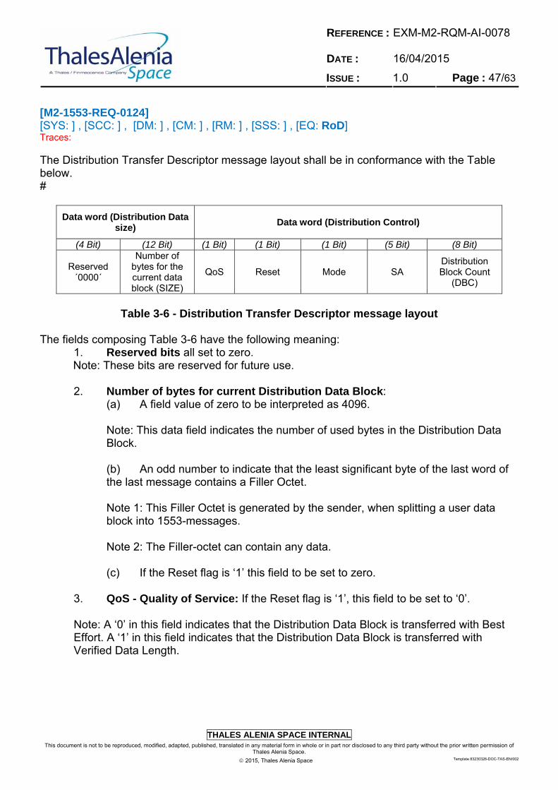
REFERENCE : DATE :
EXM-M2-RQM-AI-0078 16/04/2015
ISSUE : 1.0 Page : 47/63
THALES ALENIA SPACE INTERNAL
This document is not to be reproduced, modified, adapted, published, translated in any material form in whole or in part nor disclosed to any third party without the prior written permission of Thales Alenia Space.
2015, Thales Alenia Space Template 83230326-DOC-TAS-EN/002
[M2-1553-REQ-0124] [SYS: ] , [SCC: ] , [DM: ] , [CM: ] , [RM: ] , [SSS: ] , [EQ: RoD] Traces: The Distribution Transfer Descriptor message layout shall be in conformance with the Table below. #
Data word (Distribution Data size)
Data word (Distribution Control)
(4 Bit) (12 Bit) (1 Bit) (1 Bit) (1 Bit) (5 Bit) (8 Bit)
Reserved ´0000´
Number of bytes for the current data block (SIZE)
QoS Reset Mode SA Distribution Block Count
(DBC)
Table 3-6 - Distribution Transfer Descriptor message layout
The fields composing Table 3-6 have the following meaning:
1. Reserved bits all set to zero. Note: These bits are reserved for future use.
2. Number of bytes for current Distribution Data Block:
(a) A field value of zero to be interpreted as 4096. Note: This data field indicates the number of used bytes in the Distribution Data Block. (b) An odd number to indicate that the least significant byte of the last word of the last message contains a Filler Octet. Note 1: This Filler Octet is generated by the sender, when splitting a user data block into 1553-messages. Note 2: The Filler-octet can contain any data.
(c) If the Reset flag is ‘1’ this field to be set to zero.
3. QoS - Quality of Service: If the Reset flag is ‘1’, this field to be set to ‘0’. Note: A ‘0’ in this field indicates that the Distribution Data Block is transferred with Best Effort. A ‘1’ in this field indicates that the Distribution Data Block is transferred with Verified Data Length.
REFERENCE : DATE :
EXM-M2-RQM-AI-0078 16/04/2015
ISSUE : 1.0 Page : 48/63
THALES ALENIA SPACE INTERNAL
This document is not to be reproduced, modified, adapted, published, translated in any material form in whole or in part nor disclosed to any third party without the prior written permission of Thales Alenia Space.
2015, Thales Alenia Space Template 83230326-DOC-TAS-EN/002
4. Reset: (a) A ‘0’ in this data field to indicate that the protocol carries on. (b) A ‘1’ in this data field to indicate that the protocol with this RT is reset.
5. Mode: (b) A ‘1’ in this data field to indicate that a single subaddress is used. (c) If the Reset flag is ‘1’, this field to be set to ‘0’.
6. SA: (a) This data field is used to indicate to which subaddress data are written. (c) If the Reset flag is ‘1’, this field to be set to ‘0’.
7. Distribution Block Count: Note: This field is a circular 8-bit-counter, identifying the current data block.
(a) To be provided by the BC, independently for each Remote Terminal Address, for Distribution Data Block identification within the Transfer Layer. (c) At the first transfer after a protocol reset, the Distribution Block Counter for the selected RT to be set to 1. (d) For each new transfer to be carried out the Distribution Block Count to be incremented by one and when it reaches 255 the next count number to be 1.
[M2-1553-REQ-0125] [SYS: ] , [SCC: ] , [DM: ] , [CM: ] , [RM: ] , [SSS: ] , [EQ: RoD] Traces: The Distribution Transfer Descriptor (DTD) shall be sent to the RT in SA 27R. # [M2-1553-REQ-0126] [SYS: ] , [SCC: RoD, T] , [DM: ] , [CM: ] , [RM: ] , [SSS: ] , [EQ: RoD] Traces: A Reset Data Block Transfer Service command, consisting of a Distribution Transfer Descriptor, shall be sent to each RT using this service before the first time the service is used, or if needed otherwise. # [M2-1553-REQ-0127] [SYS: ] , [SCC: RoD, T] , [DM: ] , [CM: ] , [RM: ] , [SSS: ] , [EQ: RoD] Traces: The Distribution Data Block shall be
1. sent to the Receive SA of the destination RT as specified by the Distribution Transfer Descriptor 2. segmented into a number of 1553 messages of maximum size, i.e. 32 words, with the first 64 bytes of the block sent to the selected SA, the next 64 bytes sent to the same SA etc.#
REFERENCE : DATE :
EXM-M2-RQM-AI-0078 16/04/2015
ISSUE : 1.0 Page : 49/63
THALES ALENIA SPACE INTERNAL
This document is not to be reproduced, modified, adapted, published, translated in any material form in whole or in part nor disclosed to any third party without the prior written permission of Thales Alenia Space.
2015, Thales Alenia Space Template 83230326-DOC-TAS-EN/002
[M2-1553-REQ-0128] [SYS: ] , [SCC: ] , [DM: ] , [CM: ] , [RM: ] , [SSS: ] , [EQ: RoD, T] Traces: The last message of a Distribution Data Block, or a single message if the data block contains 64 bytes or less, shall be allowed to be shorter. # [M2-1553-REQ-0129] [SYS: ] , [SCC: ] , [DM: ] , [CM: ] , [RM: ] , [SSS: ] , [EQ: RoD, T] Traces: The last message of a Distribution Data Block, or a single message if the data block contains 64 bytes or less, shall transfer what remains of the data block including a possible single Filler Octet. # [M2-1553-REQ-0130] [SYS: ] , [SCC: RoD, T] , [DM: ] , [CM: ] , [RM: ] , [SSS: ] , [EQ: ] Traces: The transfers resulting from a Distribution Data Block followed by its Distribution Transfer Descriptor message (DTD) shall be completed within one Communication Frame. # [M2-1553-REQ-0131] [SYS: ] , [SCC: ] , [DM: ] , [CM: ] , [RM: ] , [SSS: ] , [EQ: RoD, T] Traces: If the QoS flag is ‘1’ the BC shall acquire the Distribution Transfer Confirmation not earlier than the second Communication Frame after a Distribution Transfer Descriptor has been sent to a certain RT. # [M2-1553-REQ-0132] [SYS: ] , [SCC: ] , [DM: ] , [CM: ] , [RM: ] , [SSS: ] , [EQ: RoD, T] Traces: If the QoS flag is ‘1’ the BC shall check the Error flag and the Distribution Block Count of the received Distribution Transfer Confirmation. # [M2-1553-REQ-0133] [SYS: ] , [SCC: ] , [DM: ] , [CM: ] , [RM: ] , [SSS: ] , [EQ: RoD, T] Traces: If the Error flag is ‘0’ and the Distribution Block Count of the received Distribution Transfer Confirmation is equal to the Distribution Block Count of the last transmitted Distribution Transfer Descriptor, the reception of the Distribution Data Block shall be declared confirmed.#
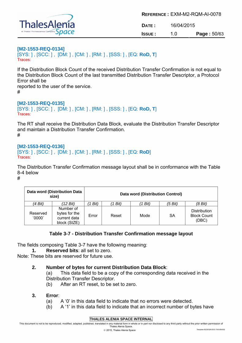
REFERENCE : DATE :
EXM-M2-RQM-AI-0078 16/04/2015
ISSUE : 1.0 Page : 50/63
THALES ALENIA SPACE INTERNAL
This document is not to be reproduced, modified, adapted, published, translated in any material form in whole or in part nor disclosed to any third party without the prior written permission of Thales Alenia Space.
2015, Thales Alenia Space Template 83230326-DOC-TAS-EN/002
[M2-1553-REQ-0134] [SYS: ] , [SCC: ] , [DM: ] , [CM: ] , [RM: ] , [SSS: ] , [EQ: RoD, T] Traces: If the Distribution Block Count of the received Distribution Transfer Confirmation is not equal to the Distribution Block Count of the last transmitted Distribution Transfer Descriptor, a Protocol Error shall be reported to the user of the service. # [M2-1553-REQ-0135] [SYS: ] , [SCC: ] , [DM: ] , [CM: ] , [RM: ] , [SSS: ] , [EQ: RoD, T] Traces: The RT shall receive the Distribution Data Block, evaluate the Distribution Transfer Descriptor and maintain a Distribution Transfer Confirmation. # [M2-1553-REQ-0136] [SYS: ] , [SCC: ] , [DM: ] , [CM: ] , [RM: ] , [SSS: ] , [EQ: RoD] Traces: The Distribution Transfer Confirmation message layout shall be in conformance with the Table 8-4 below #
Data word (Distribution Data size)
Data word (Distribution Control)
(4 Bit) (12 Bit) (1 Bit) (1 Bit) (1 Bit) (5 Bit) (8 Bit)
Reserved ´0000´
Number of bytes for the current data block (SIZE)
Error Reset Mode SA Distribution Block Count
(DBC)
Table 3-7 - Distribution Transfer Confirmation message layout
The fields composing Table 3-7 have the following meaning:
1. Reserved bits: all set to zero. Note: These bits are reserved for future use.
2. Number of bytes for current Distribution Data Block: (a) This data field to be a copy of the corresponding data received in the Distribution Transfer Descriptor. (b) After an RT reset, to be set to zero.
3. Error: (a) A ‘0’ in this data field to indicate that no errors were detected. (b) A ‘1’ in this data field to indicate that an incorrect number of bytes have

REFERENCE : DATE :
EXM-M2-RQM-AI-0078 16/04/2015
ISSUE : 1.0 Page : 51/63
THALES ALENIA SPACE INTERNAL
This document is not to be reproduced, modified, adapted, published, translated in any material form in whole or in part nor disclosed to any third party without the prior written permission of Thales Alenia Space.
2015, Thales Alenia Space Template 83230326-DOC-TAS-EN/002
been received. (c) After an RT reset or a protocol reset, this bit to be ‘0’.
4. Reset: (a) A ‘0’ in this data field to indicate that the protocol carries on. (b) A ‘1’ in this data field to indicate that a protocol reset or an RT reset has been carried out.
5. Mode: (a) This data field to be a copy of the Mode flag received in the Distribution Transfer Descriptor. (b) After an RT reset, to be set to ‘0’.
6. SA: (a) This data field to be a copy of the corresponding data received in the Distribution Transfer Descriptor. (b) After an RT reset, to be set to zero.
7. Distribution Block Count: (a) This data field to be a copy of the corresponding data received in the Distribution Transfer Descriptor.
(b) After an RT reset this field to be set to zero. [M2-1553-REQ-0137] [SYS: ] , [SCC: ] , [DM: ] , [CM: ] , [RM: ] , [SSS: ] , [EQ: RoD, T] Traces: Within the Communication Frame following the frame in which the Distribution Transfer Descriptor is received, the RT shall perform the following:
1. If the Reset flag is ‘0’ and the Mode flag indicates a transfer mode supported by the RT, compare the Distribution Data Count from the received DTD with the Distribution Data Count of the current Distribution Transfer Confirmation as follows:
(a) If a difference is found and if the QoS flag is ‘0’, the associated Distribution Data Block be accepted (new Distribution Data, new command) and the Distribution Transfer Confirmation be updated with the Error and Reset flags cleared. (b) If a difference is found and if the QoS flag is ‘1’ and the number of correctly received bytes does match the number of bytes in the Distribution Transfer Descriptor, the associated Distribution Data Block be accepted (new Distribution Data, new command) and the Distribution Transfer Confirmation be updated with the Error and Reset flags cleared. (c) If a difference is found and if the QoS flag is ‘1’ and the number of correctly received bytes does not match the number of bytes in the Distribution Transfer
REFERENCE : DATE :
EXM-M2-RQM-AI-0078 16/04/2015
ISSUE : 1.0 Page : 52/63
THALES ALENIA SPACE INTERNAL
This document is not to be reproduced, modified, adapted, published, translated in any material form in whole or in part nor disclosed to any third party without the prior written permission of Thales Alenia Space.
2015, Thales Alenia Space Template 83230326-DOC-TAS-EN/002
Descriptor, ignore the distribution data block, the Distribution Transfer Confirmation being updated with the Error flag set and the Reset flag reset. Note: The RT may optionally report the failure to the user of the service within the RT-unit. (d) If no difference is found, ignore the associated Distribution Data Block (no new data) and keep the Distribution Transfer Confirmation unchanged. Note: It is not necessary that the Distribution Data Counter has been incremented by only one. Any new data (command) can be accepted.
2. If the Reset flag is ‘0’ and the Mode flag indicates a transfer mode that is not supported by the RT the associated Distribution Data Block is ignored (no new data) and the Distribution Transfer Confirmation unchanged. 3. If the Reset flag is ‘1’ the Distribution Transfer Confirmation is updated with the Reset flag set to indicate that a protocol reset has been carried out. #
[M2-1553-REQ-0138] [SYS: ] , [SCC: ] , [DM: ] , [CM: ] , [RM: ] , [SSS: ] , [EQ: RoD, T] Traces: If accepted data have arrived, the RT shall deliver the data block to the service destination user, stripping off any Filler Octet. #
3.5.6.2 Data Acquisition
[M2-1553-REQ-0139] [SYS: ] , [SCC: RoD, T] , [DM: ] , [CM: ] , [RM: ] , [SSS: ] , [EQ: RoD] Traces: The BC shall perform the polling of Acquisition Transfer Request from all active RT at each Communication Frame. # [M2-1553-REQ-0141] [SYS: ] , [SCC: ] , [DM: ] , [CM: ] , [RM: ] , [SSS: ] , [EQ: RoD, T] Traces: The BC shall be able to collect up to 2500 bytes (TBC) at maximum through data block acquisition transfers per Communication Frame. #
REFERENCE : DATE :
EXM-M2-RQM-AI-0078 16/04/2015
ISSUE : 1.0 Page : 53/63
THALES ALENIA SPACE INTERNAL
This document is not to be reproduced, modified, adapted, published, translated in any material form in whole or in part nor disclosed to any third party without the prior written permission of Thales Alenia Space.
2015, Thales Alenia Space Template 83230326-DOC-TAS-EN/002
[M2-1553-REQ-0142] [SYS: ] , [SCC: ] , [DM: ] , [CM: ] , [RM: ] , [SSS: ] , [EQ: RoD] Traces: The BC shall maintain, for each Remote Terminal Address using the protocol, an Acquisition Block Counter value of the last Acquisition Data Block received. # [M2-1553-REQ-0143] [SYS: ] , [SCC: RoD, T] , [DM: ] , [CM: ] , [RM: ] , [SSS: ] , [EQ: RoD] Traces: At BC initialization or restart, all maintained Acquisition Block Counters for all RTs shall be set to 0 and an Acquisition Protocol Reset Request shall be sent to each RT using a Reset_Services command. # [M2-1553-REQ-0144] [SYS: ] , [SCC: RoD, T] , [DM: ] , [CM: ] , [RM: ] , [SSS: ] , [EQ: RoD] Traces: When an Acquisition Protocol Reset Request has been sent to an RT, the BC shall not poll the Acquisition Transfer Request of that RT earlier than the second Communication Frame following the Communication Frame in which the reset was sent. # [M2-1553-REQ-0145] [SYS: ] , [SCC: ] , [DM: ] , [CM: ] , [RM: ] , [SSS: ] , [EQ: RoD, T] Traces: The poll of the RT for a need of transfer shall be done by reading the RT Acquisition Transfer Request message from SA 28T. # [M2-1553-REQ-0146] [SYS: ] , [SCC: ] , [DM: ] , [CM: ] , [RM: ] , [SSS: ] , [EQ: RoD, T] Traces: If the Reset flag is ‘0’, the BC shall identify a new Acquisition Transfer Request by evaluation of the Acquisition Block Count value with comparison to the stored one and do the following:
1. If these values are not identical: acquire the block using subaddresses. 2. If these values are identical, ignore the request (no new data). #

REFERENCE : DATE :
EXM-M2-RQM-AI-0078 16/04/2015
ISSUE : 1.0 Page : 54/63
THALES ALENIA SPACE INTERNAL
This document is not to be reproduced, modified, adapted, published, translated in any material form in whole or in part nor disclosed to any third party without the prior written permission of Thales Alenia Space.
2015, Thales Alenia Space Template 83230326-DOC-TAS-EN/002
[M2-1553-REQ-0147] [SYS: ] , [SCC: RoD, T] , [DM: ] , [CM: ] , [RM: ] , [SSS: ] , [EQ: RoD] Traces: If the Reset flag is ‘1’ the BC shall send an Acquisition Transfer Confirmation with the Reset bit set to ‘1’ to indicate that a protocol reset is granted and has been carried out on the BC side. The Acquisition Transfer Confirmation shall be sent during the second Communication Frame, which follows the Communication Frame in which the acquisition was carried out. # [M2-1553-REQ-0148] [SYS: ] , [SCC: ] , [DM: ] , [CM: ] , [RM: ] , [SSS: ] , [EQ: RoD, T] Traces: If the QoS flag is ‘0’ or the QoS flag is ‘1’ and data have been acquired without transmission errors, the BC shall:
1. deliver the user data to the BC service destination user, stripping off any Filler Octet. 2. update the stored Acquisition Block Counter with the value of the received Acquisition Data Count. 3. send an Acquisition Transfer Confirmation with this updated Acquisition Block Count and the Error flag set to ‘0’ to SA 28R of the RT. 4. in case the QoS flag is ‘0’, send the Acquisition Transfer Confirmation within the same Communication Frame in which the acquisition was carried out. 5. in case the QoS flag is ‘1’, send the Acquisition Transfer Confirmation at the latest during the second Communication Frame, which follows the Communication Frame in which the acquisition was carried out. #
[M2-1553-REQ-0149] [SYS: ] , [SCC: ] , [DM: ] , [CM: ] , [RM: ] , [SSS: ] , [EQ: RoD, T] Traces: If the QoS flag is ‘1’ and data have been acquired with transmission errors, the BC shall:
1. update the stored Acquisition Block Counter with the value of the received Acquisition Data Counter. 2. send an Acquisition Transfer Confirmation with this updated Acquisition Block Counter and the Error flag set to ‘1’ to SA 28R of the RT. Note: The BC can optionally report the failure to the user of the service within the BC unit.

REFERENCE : DATE :
EXM-M2-RQM-AI-0078 16/04/2015
ISSUE : 1.0 Page : 55/63
THALES ALENIA SPACE INTERNAL
This document is not to be reproduced, modified, adapted, published, translated in any material form in whole or in part nor disclosed to any third party without the prior written permission of Thales Alenia Space.
2015, Thales Alenia Space Template 83230326-DOC-TAS-EN/002
3. send the Acquisition Transfer Confirmation at the latest during the second Communication Frame, which follows the Communication Frame in which the acquisition was carried out. #
[M2-1553-REQ-0150] [SYS: ] , [SCC: ] , [DM: ] , [CM: ] , [RM: ] , [SSS: ] , [EQ: RoD] Traces: The layout of the Acquisition Transfer Confirmation shall be in conformance with the following Table. #
Data word (Distribution Data size)
Data word (Distribution Control)
(4 Bit) (12 Bit) (1 Bit) (1 Bit) (1 Bit) (5 Bit) (8 Bit)
Reserved ´0000´
Number of bytes for the current data block (SIZE)
Error Reset Mode SA Acquisition Block Count
(ABC)
Table 3-8 - Acquisition Transfer Confirmation message layout The fields composing Table 3-8 have the following meaning:
1. Reserved bits: all to be set to zero. Note: These bits are reserved for later use.
2. Number of bytes for next Acquisition Data Block: to be a copy of the corresponding data in the Acquisition Transfer Request acquired from the RT. 3. Error:
(a) A ‘0’ in this data field to indicate that the transfer was successfully completed. (b) A ‘1’ in this data field to indicate that the data was transferred with errors. (c) After a protocol reset, set this bit to ‘0’.
4. Reset: (a) A ‘1’ in this data field to indicate that a protocol reset request is granted. (b) A ‘0’ in this data field to indicate that the protocol carries on.
5. Mode: to be a copy of the Mode flag in the Acquisition Transfer Request acquired from the RT. 6. SA: to be a copy of the corresponding data received in the Distribution Transfer Descriptor.
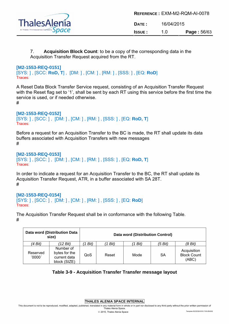
REFERENCE : DATE :
EXM-M2-RQM-AI-0078 16/04/2015
ISSUE : 1.0 Page : 56/63
THALES ALENIA SPACE INTERNAL
This document is not to be reproduced, modified, adapted, published, translated in any material form in whole or in part nor disclosed to any third party without the prior written permission of Thales Alenia Space.
2015, Thales Alenia Space Template 83230326-DOC-TAS-EN/002
7. Acquisition Block Count: to be a copy of the corresponding data in the Acquisition Transfer Request acquired from the RT.
[M2-1553-REQ-0151] [SYS: ] , [SCC: RoD, T] , [DM: ] , [CM: ] , [RM: ] , [SSS: ] , [EQ: RoD] Traces: A Reset Data Block Transfer Service request, consisting of an Acquisition Transfer Request with the Reset flag set to ‘1’, shall be sent by each RT using this service before the first time the service is used, or if needed otherwise. # [M2-1553-REQ-0152] [SYS: ] , [SCC: ] , [DM: ] , [CM: ] , [RM: ] , [SSS: ] , [EQ: RoD, T] Traces: Before a request for an Acquisition Transfer to the BC is made, the RT shall update its data buffers associated with Acquisition Transfers with new messages # [M2-1553-REQ-0153] [SYS: ] , [SCC: ] , [DM: ] , [CM: ] , [RM: ] , [SSS: ] , [EQ: RoD, T] Traces: In order to indicate a request for an Acquisition Transfer to the BC, the RT shall update its Acquisition Transfer Request, ATR, in a buffer associated with SA 28T. # [M2-1553-REQ-0154] [SYS: ] , [SCC: ] , [DM: ] , [CM: ] , [RM: ] , [SSS: ] , [EQ: RoD] Traces: The Acquisition Transfer Request shall be in conformance with the following Table. #
Data word (Distribution Data size)
Data word (Distribution Control)
(4 Bit) (12 Bit) (1 Bit) (1 Bit) (1 Bit) (5 Bit) (8 Bit)
Reserved ´0000´
Number of bytes for the current data block (SIZE)
QoS Reset Mode SA Acquisition Block Count
(ABC)
Table 3-9 - Acquisition Transfer Transfer message layout
REFERENCE : DATE :
EXM-M2-RQM-AI-0078 16/04/2015
ISSUE : 1.0 Page : 57/63
THALES ALENIA SPACE INTERNAL
This document is not to be reproduced, modified, adapted, published, translated in any material form in whole or in part nor disclosed to any third party without the prior written permission of Thales Alenia Space.
2015, Thales Alenia Space Template 83230326-DOC-TAS-EN/002
The fields composing Table 3-9 have the following meaning:
1. Reserved bits: all to be set to zero. Note: These bits are reserved for later use.
2. Number of bytes for current Acquisition Data Block:
(a) This data field to indicate the number of bytes in the Acquisition Data Block. (b) A field value of zero to be interpreted as 4096. (c) An odd number to indicate that the least significant byte of the last word of the last message contains a Filler Octet.
Note 1: This Filler Octet is generated by the sender, when splitting a user data block into 1553-messages. Note 2: The Filler-octet can contain any data. (d) If the Reset flag is ‘1’ this field to be set to zero.
3. QoS - Quality of Service:
(a) A ‘0’ in this field to indicate that the Acquisition Data Block is transferred with Best Effort. (b) A ‘1’ in this field to indicate that the Acquisition Data Block is transferred with Verified Data Length. (c) If the Reset flag is ‘1’ this field to be set to ‘0’.
4. Reset: (a) A ‘0’ in this data field to indicate that the protocol carries on. (b) A ‘1’ in this data field to indicate that a protocol reset is requested or that the RT has been reset.
5. Mode: (b) A ‘1’ in this data field to indicate that a single subaddress is used. (c) If the Reset flag is ‘1’ this field to be set to ‘0’.
6. SA: (a) This data field to indicate to which subaddress data are written.
7. Acquisition Block Count: Note: This field is a circular 8-bit-counter, identifying the current data block.
(a) If the Reset flag is ‘1’ the Acquisition Block Count to be set to zero. (b) At the first transfer after a protocol reset, the Acquisition Block Count to be set to 1.
REFERENCE : DATE :
EXM-M2-RQM-AI-0078 16/04/2015
ISSUE : 1.0 Page : 58/63
THALES ALENIA SPACE INTERNAL
This document is not to be reproduced, modified, adapted, published, translated in any material form in whole or in part nor disclosed to any third party without the prior written permission of Thales Alenia Space.
2015, Thales Alenia Space Template 83230326-DOC-TAS-EN/002
[M2-1553-REQ-0155] [SYS: ] , [SCC: ] , [DM: ] , [CM: ] , [RM: ] , [SSS: ] , [EQ: RoD] Traces: When the RT is polled for a Request, the ATR shall be consistent. # [M2-1553-REQ-0156] [SYS: ] , [SCC: ] , [DM: ] , [CM: ] , [RM: ] , [SSS: ] , [EQ: RoD, T] Traces: If an RT is declared as ready for new ATR transmission, it shall generate a new Acquisition Transfer Request only after occurrence of one of the following conditions:
1. After a protocol reset. 2. Reception of an Acquisition Transfer Confirmation with the same Acquisition Block Count as the currently outstanding Acquisition Transfer Request. #
[M2-1553-REQ-0157] [SYS: ] , [SCC: ] , [DM: ] , [CM: ] , [RM: ] , [SSS: ] , [EQ: RoD, T] Traces: In case the RT does not receive any Acquisition Transfer Confirmation within the expected time, the RT application shall maintain a timeout of TBD ms in order to request a protocol reset before any new transfer request is made. # [M2-1553-REQ-0158] [SYS: ] , [SCC: RoD, T] , [DM: ] , [CM: ] , [RM: ] , [SSS: ] , [EQ: RoD] Traces: The Acquisition Data Block shall be:
1. available in the Transmit SA of the source RT as specified by the Acquisition Transfer Request. 2. segmented into a number of 1553 messages of maximum size, i.e. 32 words, with the first 64 bytes of the block available in the selected SA, the next 64 bytes in the same SA etc. #
[M2-1553-REQ-0159] [SYS: ] , [SCC: ] , [DM: ] , [CM: ] , [RM: ] , [SSS: ] , [EQ: RoD, T] Traces: The last message, or a single message if the data block contains 64 bytes or less, shall be allowed to be shorter.#

REFERENCE : DATE :
EXM-M2-RQM-AI-0078 16/04/2015
ISSUE : 1.0 Page : 59/63
THALES ALENIA SPACE INTERNAL
This document is not to be reproduced, modified, adapted, published, translated in any material form in whole or in part nor disclosed to any third party without the prior written permission of Thales Alenia Space.
2015, Thales Alenia Space Template 83230326-DOC-TAS-EN/002
[M2-1553-REQ-0160] [SYS: ] , [SCC: ] , [DM: ] , [CM: ] , [RM: ] , [SSS: ] , [EQ: RoD] Traces: The last message (see requirement EXM-1553-13-REQ-1440), or a the single message if the data block contains 64 bytes or less, shall transfer what remains of the data block including a possible single Filler Octet. # [M2-1553-REQ-0161] [SYS: ] , [SCC: ] , [DM: ] , [CM: ] , [RM: ] , [SSS: ] , [EQ: RoD, T] Traces: When there is an outstanding transfer request or protocol reset request, the RT shall check the Acquisition Transfer Confirmation after each Communication Frame Synchronisation Message and perform the following:
1. signal its service user that the protocol reset is completed, if the Reset flag is ‘1’. 2. signal its service user that the transfer is completed, if the Acquisition Block Count of the Acquisition Transfer Confirmation is identical to the Acquisition Block Count of the currently outstanding Acquisition Transfer Request and the QoS flag is ‘0’. 3. signal its service user that the transfer is successful, if the Acquisition Block Count of the Acquisition Transfer Confirmation is identical to the Acquisition Block Count of the currently outstanding Acquisition Transfer Request and the QoS flag is ‘1’ and the Error flag of the Acquisition Transfer Confirmation is ‘0’. 4. signal its service user that the transfer is unsuccessful, if the Acquisition Block Count of the Acquisition Transfer Confirmation is identical to the Acquisition Block Count of the currently outstanding Acquisition Transfer Request and the QoS flag is ‘1’ and the Error flag of the Acquisition Transfer Confirmation is ‘1’. #
3.5.7 Transfer Layer FDIR
[M2-1553-REQ-0162] [SYS: ] , [SCC: RoD, T] , [DM: ] , [CM: ] , [RM: ] , [SSS: ] , [EQ: ] Traces: The 1553 SW driver shall notify to the application if an error occurs performing a transaction, i.e. if at least one command block fails. If the Failure Identification Algorithm identifies a failure specific reason (SW Errors, Bus Controller Busy, Remote Terminal Error, Bus or Bus Controller Failure or Multiple Error) the bus 1553 driver shall notify the relevant error code to the application SW. Otherwise it shall return to the application the generic transaction "NOT OK" message to notify the generic transaction failure. #
REFERENCE : DATE :
EXM-M2-RQM-AI-0078 16/04/2015
ISSUE : 1.0 Page : 60/63
THALES ALENIA SPACE INTERNAL
This document is not to be reproduced, modified, adapted, published, translated in any material form in whole or in part nor disclosed to any third party without the prior written permission of Thales Alenia Space.
2015, Thales Alenia Space Template 83230326-DOC-TAS-EN/002
[M2-1553-REQ-0163] [SYS: ] , [SCC: RoD] , [DM: ] , [CM: ] , [RM: ] , [SSS: ] , [EQ: ] Traces: The 1553 SW driver shall implement a mechanism to detect and notify to the application whether a set number of consecutive command blocks toward the same Remot Terminal (RT) fails (RT Failure identification capability). The enabling status and the threshold number shall be configurable for each RT. # [M2-1553-REQ-0164] [SYS: ] , [SCC: RoD] , [DM: ] , [CM: ] , [RM: ] , [SSS: ] , [EQ: ] Traces: The 1553 SW driver shall implement a mechanism to detect whether a set number of consecutive command blocks fail, regardless the RT they are addressed to (Communication Channel Failure identification capability). The enabling status and the threshold number shall be configurable. # [M2-1553-REQ-0165] [SYS: ] , [SCC: RoD] , [DM: ] , [CM: ] , [RM: ] , [SSS: ] , [EQ: ] Traces: The 1553 SW driver shall implement a mechanism to detect whether a set number of different Remote Terminals have at least one transaction error in 1 second time window (Communication Channel Multiple Error in Period identification capability). The enabling status and the threshold number shall be configurable. # [M2-1553-REQ-0166] [SYS: ] , [SCC: RoD, T] , [DM: ] , [CM: ] , [RM: ] , [SSS: ] , [EQ: ] Traces: When the Communication Channel Failure is asserted, being a Channel Failure or Multiple Error in Period, and the on-control physical channel is the SFO one (i.e. the Selected For Operations) then the 1553 SW driver shall notify to the application the related Bus Failure code (BUS Failure or Bus Multiple Error in Period), and perform an on-line Bus channel swap recovery by re-addressing all the 1553 transactions to the SFR physical channel. #
REFERENCE : DATE :
EXM-M2-RQM-AI-0078 16/04/2015
ISSUE : 1.0 Page : 61/63
THALES ALENIA SPACE INTERNAL
This document is not to be reproduced, modified, adapted, published, translated in any material form in whole or in part nor disclosed to any third party without the prior written permission of Thales Alenia Space.
2015, Thales Alenia Space Template 83230326-DOC-TAS-EN/002
[M2-1553-REQ-0167] [SYS: ] , [SCC: RoD, T] , [DM: ] , [CM: ] , [RM: ] , [SSS: ] , [EQ: ] Traces: The 1553 SW driver during the execution of the on-line Bus channel swap recovery shall suspend all the 1553 SW driver monitoring activities and reset the relevant confirmation counters # [M2-1553-REQ-0168] [SYS: ] , [SCC: RoD, T] , [DM: ] , [CM: ] , [RM: ] , [SSS: ] , [EQ: ] Traces: The 1553 SW driver shall complete the on-line Bus channel swap recovery, by re-addressing all the 1553 transactions to the SFR physical channel, in less than 3 seconds. # [M2-1553-REQ-0169] [SYS: ] , [SCC: RoD, T] , [DM: ] , [CM: ] , [RM: ] , [SSS: ] , [EQ: ] Traces: When the Communication Channel Failure is asserted, being a Channel Failure or Multiple Error in Period, and the on-control physical channel is already the the SFR one (i.e. the Selected For Recovery) then the 1553 SW driver shall notify to the application the related Bus Controller Failure code (BC Failure or BC Multiple Error in Period). # [M2-1553-REQ-0170] [SYS: ] , [SCC: RoD] , [DM: ] , [CM: ] , [RM: ] , [SSS: ] , [EQ: ] Traces: The bus 1553 Recovery function shall be demanded to the ASW application layer. The only one Recovery handled at 1553 SW driver level is the physical channel bus swap in case of communication channel failure detection on SFO (i.e. if Bus redundancy can be spent). # [M2-1553-REQ-0171] [SYS: ] , [SCC: RoD, T] , [DM: ] , [CM: ] , [RM: ] , [SSS: ] , [EQ: ] Traces: When a return code different than "OK" is notified, regardless the relevant monitoring is confirmed or not, the acquired data pool shall be flagged invalid. #
REFERENCE : DATE :
EXM-M2-RQM-AI-0078 16/04/2015
ISSUE : 1.0 Page : 62/63
THALES ALENIA SPACE INTERNAL
This document is not to be reproduced, modified, adapted, published, translated in any material form in whole or in part nor disclosed to any third party without the prior written permission of Thales Alenia Space.
2015, Thales Alenia Space Template 83230326-DOC-TAS-EN/002
[M2-1553-REQ-0172] [SYS: ] , [SCC: RoD, T] , [DM: ] , [CM: ] , [RM: ] , [SSS: ] , [EQ: ] Traces: When the acquired data pool is flagged invalid the application SW shall ignore the not-valid data by not using them at all (nor for controlling, nor for monitoring). # [M2-1553-REQ-0173] [SYS: ] , [SCC: RoD, T] , [DM: ] , [CM: ] , [RM: ] , [SSS: ] , [EQ: ] Traces: In case of SW errors (i.e. inconsistent requests to low level drivers) or Bus Controller errors (Bus Controller Busy included) the application layer shall immediately trigger an ASW Restart (i.e. a Level-2 Recovery). # [M2-1553-REQ-0174] [SYS: ] , [SCC: RoD] , [DM: ] , [CM: ] , [RM: ] , [SSS: ] , [EQ: ] Traces: In case of RT Error detection the ASW shall be in charge for managing the failure as per the monitored unit criticality. This type of monitoring shall have, at application level, a confirmation time larger than one second to allow earlier Multiple Errors in Period identification. #
REFERENCE : DATE :
EXM-M2-RQM-AI-0078 16/04/2015
ISSUE : 1.0 Page : 63/63
THALES ALENIA SPACE INTERNAL
This document is not to be reproduced, modified, adapted, published, translated in any material form in whole or in part nor disclosed to any third party without the prior written permission of Thales Alenia Space.
2015, Thales Alenia Space Template 83230326-DOC-TAS-EN/002
END OF DOCUMENT