Embed Size (px)
Citation preview
ST 100 Stacking TowerShoring
Assembly Instructions for Standard Configuration
Edition 02/2009


OverviewOverview 1
IntroductionStandard configuration 2
Intended use 2
Safety instructions 3
Additional PERI product information 3
A Assembly and dismantlingA1 Storage and transportation 4
A2 Horizontal assembly
Assembly of the base 5
Assembly of the tower 6
Assembly ofthe diagonal bracing 6
Head spindles 7
Erecting the tower 7
A3 Vertical assembly
Assembly of the base 8
Assembly of the tower 8
Moving with the crane 9
A4 Dismantling 10
A5 Material requirements 11
TablesST 100 tables 12
ComponentsComponents 18
Key
Important safety
Instructions Note Visual check Tip
Assembly Instructions for Standard Configuration
ContentsST 100 Stacking Tower
1
5
2
7
6
1
4.1 4.2
6
8
1
3
Assembly Instructions for Standard Configuration
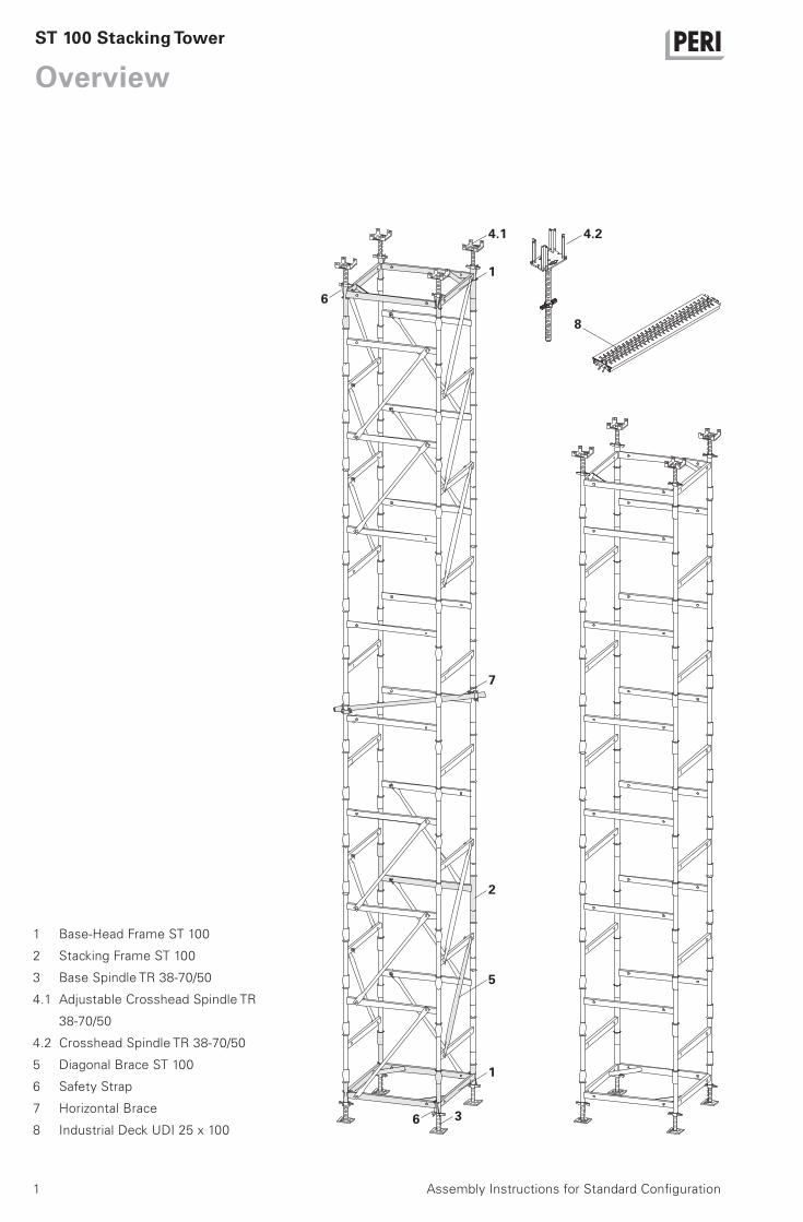
OverviewST 100 Stacking Tower
1 Base-Head Frame ST 100
2 Stacking Frame ST 100
3 Base Spindle TR 38-70/50
4.1 Adjustable Crosshead Spindle TR
38-70/50
4.2 Crosshead Spindle TR 38-70/50
5 Diagonal Brace ST 100
6 Safety Strap
7 Horizontal Brace
8 Industrial Deck UDI 25 x 100

2 Assembly Instructions for Standard Configuration
ST 100 Stacking Tower
Introduction
GeneralThe structures presented in these as-
sembly instructions are shown in the
form of examples with only one compo-
nent size. They are valid accordingly for
all component sizes contained in the
standard configuration.
FeaturesThe PERI ST 100 Stacking Tower is used
for shoring purposes. The tower can be
used either free-standing or restrained
at the top.
All permissible heights can be assem-
bled using only one type of stacking
frame. Connecting the stacking frame
is carried out without any small parts -
simply slotted together! If required,
tension-proof connections are achieved
using diagonal bracing.
Assembly and dismantling is possible
both vertically and horizontally without
the use of a crane.
The ST 100 is completely galvanized
and maintenance-free.
Standard configuration
Intended use1. PERI products have been exclusively
designed as technical work equipment
and are only intended for commercial
use by technically competent users.
2. These assembly instructions serve as
a basis for the building-related risk eval-
uation and the instructions for the provi-
sion and use of the system by the con-
tractor (users). However, this does not
replace these.
3. Only PERI original components may
be used. The use of other products and
spare parts represent a misapplication
with associated safety risks.
4. The components are to be inspected
before each use to ensure that they are
in perfect condition as well as function-
ing correctly.
5. Changes to PERI components are
not permitted and represent a misappli-
cation with associated safety risks.
6. Safety instructions and permissible
loads are to be observed at all times.
7. Components supplied by the contrac-
tor must comply with the characteris-
tics required in these assembly instruc-
tions and all valid regulations and
standards.
In particular, the following apply if noth-
ing else is specified:
– timber components: Strength Class
C24 for Solid Wood EN 338.
– scaffold tubes: galvanized steel tub-
ing with minimum dimensions Ø 48.3
x 3.2 mm according to EN 12811-
1:2003 4.2.1.2.
– scaffold tube couplings according to
EN 74.
8. Any deviations from the standard
configuration may only be carried out
after a separate risk evaluation by the
contractor (user). On this basis, appro-
priate measures for the working safety
and stability are to be implemented.
Main componentsBase-Head Frame ST 100
Stacking Frame ST 100
Diagonal Brace ST 100
Head and Base Spindles ST 100
System dimensionsAssembly heights up to 22.29 m.
Square-shaped layout with 1.00 m x
1.00 m axial dimensions.
Technical dataPermissible load-bearing capacities: see
type tests and PERI design tables.


3Assembly Instructions for Standard Configuration
ST 100 Stacking Tower
Introduction
Safety instructions
– ST 100 Stacking Tower brochure
– ST 100 Stacking Tower type test
– PERI design tables
– Instructions for use for pallets and
stacking devices
General1. Deviations from the standard configu-
ration and/or intended use present a
potential safety risk.
2. All country-specific laws, standards
and other safety regulations are to be
taken into account when are products
are used.
3. During unfavourable weather condi-
tions, suitable precautions and meas-
ures are to be taken in order to ensure
both working safety and stability.
4. The contractor (user) must ensure
stability during all stages of construc-
tion. He has to ensure and verify that all
loads which occur are safely trans-
ferred.
5. The contractor (user) has to provide
safe working areas which can be safely
accessed. Areas of risk must be cor-
doned off and clearly marked. Hatches
and openings on accessible working ar-
eas must be kept closed during work-
ing operations.
6. For the sake of clarity, detailed pres-
entations are partly incomplete. The
safety installations which have possibly
not been shown in these detailed de-
scriptions must nevertheless be availa-
ble.
Storage and transportation1. Do not drop the components.
2. Store and transport components so
that no unintentional change in their po-
sition is possible. Detach lifting gear
from the lowered units only if these are
in a stable position and no unintentional
change is possible.
3. When moving the components, make
sure they are lifted and set down so
that any unintentional tilting over, falling
apart, sliding or rolling away is avoided.
4. Use only suitable load-carrying equip-
ment to move the components as well
as the designated load-bearing points.
5. Remove or secure any loose compo-
nents during moving procedures.
6. During the moving procedure, always
use a guide rope.
7. Move components only on clean, flat
and sufficiently load-bearing surfaces.
System-specific1. Retract components only when the
concrete has sufficiently hardened and
the person in charge has given the go-
ahead for striking to take place.
2. Anchoring is to take place only if the
anchorage has sufficient concrete
strength.
Additional PERI product information
PERI Paletten undStapelrungen
Bedienungsanleitung
Ausgabe 05/2007
4
A1 Storage and transportation
Assembly Instructions for Standard Configuration
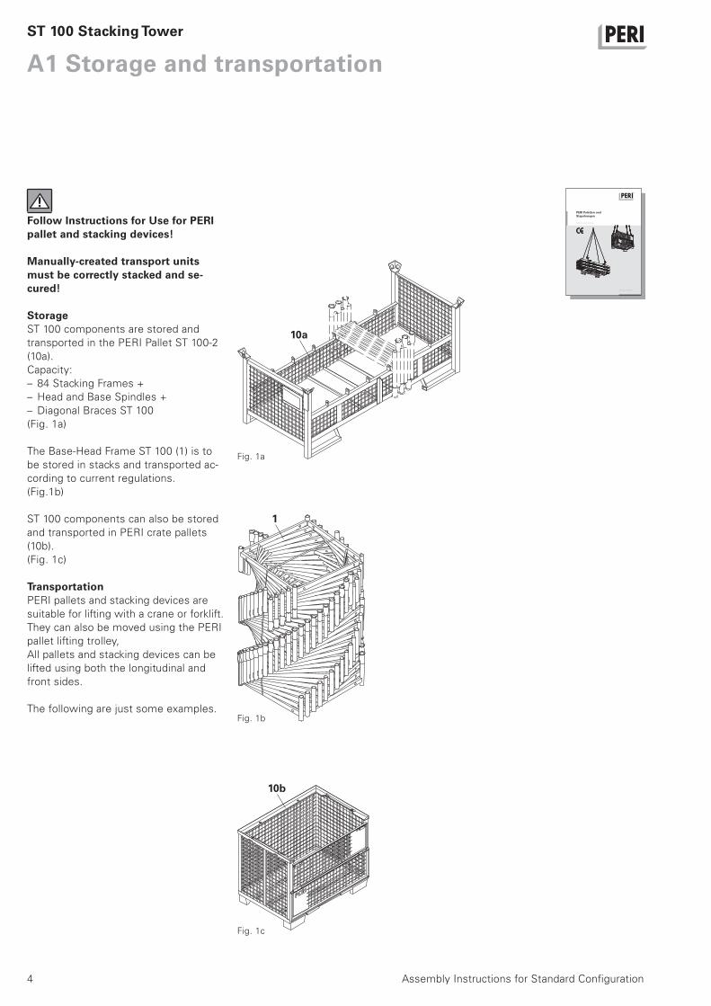
Follow Instructions for Use for PERI pallet and stacking devices!
Manually-created transport units must be correctly stacked and se-cured!
StorageST 100 components are stored and
transported in the PERI Pallet ST 100-2
(10a).
Capacity:
– 84 Stacking Frames +
– Head and Base Spindles +
– Diagonal Braces ST 100
(Fig. 1a)
The Base-Head Frame ST 100 (1) is to
be stored in stacks and transported ac-
cording to current regulations.
(Fig.1b)
ST 100 components can also be stored
and transported in PERI crate pallets
(10b).
(Fig. 1c)
TransportationPERI pallets and stacking devices are
suitable for lifting with a crane or forklift.
They can also be moved using the PERI
pallet lifting trolley,
All pallets and stacking devices can be
lifted using both the longitudinal and
front sides.
The following are just some examples.
ST 100 Stacking Tower
Fig. 1a
Fig. 1b
Fig. 1c
10a
1
10b
5Assembly Instructions for Standard Configuration
A2 Horizontal assembly
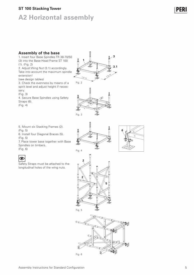
Assembly of the base1. Insert four Base Spindles TR 38-70/50
(3) into the Base-Head Frame ST 100
(1). (Fig. 2)
2. Adjust Wing Nut (3.1) accordingly.
Take into account the maximum spindle
extension!
(see design tables)
3. Check the evenness by means of a
spirit level and adjust height if neces-
sary.
(Fig. 3)
4. Secure Base Spindles using Safety
Straps (6).
(Fig. 4)
ST 100 Stacking Tower
Fig. 3
Fig. 4
Fig. 5
Fig. 6
Fig. 2
m
m1,0 1,0
6
2
2
5
13
3.1
5. Mount six Stacking Frames (2).
(Fig. 5)
6. Install four Diagonal Braces (5).
(Fig. 5)
7. Place tower base together with Base
Spindles on timbers.
(Fig. 6)
Safety Straps must be attached to the
longitudinal holes of the wing nuts.

6
A2 Horizontal assembly
Assembly Instructions for Standard Configuration
Assembly of the tower
During horizontal assembly, ensure that all diagonal braces and safety straps are installed!
1. Mount Base-Head Frames (2) up to
the required height (4 pieces per metre
of height).
(Fig. 7)
2. Install Diagonal Braces (5) keeping
pace with assembly progress.
Assembly: see below
3. Insert Base-Head Frame (1).
(Fig. 8)
4. Adjust Head Spindle (4) accordingly.
Take into account tne maximum spindle
extension!
(see design tables)
5. Insert into the Base-Head Frame and
secure by means of Safety Straps (6).
(Fig. 9)
The stacking tower is now tensile and
compression-proof connected.
For tower heights h > 8.30 m, a hori-
zontal brace (7) is to be mounted in or-
der to ensure the cross-sectional form,
approx. for h/2, see A3.
This consists of: 1 x scaffold tube ø
48.3 and 2 x standard couplings.
ST 100 Stacking Tower
Fig. 9b Fig. 9a
Fig. 7
Fig. 8
Fig. 9
5
1
4
5.2
5.1
2
Assembly of the diagonal bracingDiagonal Braces can be internally or ex-
ternally-mounted on the ST 100 Stack-
ing Frame.
1. Attach pin (5.1) to the Base-Head
Frame or Stacking Frame.
(Fig. 9a)
2. Fix to the next highest Stacking
Frame by means of gravity pin (5.2).
(Fig. 9b)
The diagonals are now tension and
compression-proof installed.
6
6

7Assembly Instructions for Standard Configuration
A2 Horizontal assembly
Head spindlesAdjustable Crosshead Spindle TR 38-70/50 (4.1)With articulated-mounted head plate.
This carries loads centrically.
The maximum tilt of the forkhead is
4.4 % on all sides.
Different types of main beams can be
used, e.g. Steel Walers SRZ/SRU or
wooden girders.
(Fig. 10a)
Crosshead Spindle TR 38-70/50 (4.2).With rigid head plate for tilt-resistant
support of one or two GT 24 or VT 20
girders.
(Fig. 10b)
ST 100 Stacking Tower
Fig. 10a
Fig. 11
Fig. 10b
4.2
4.1
Erecting the tower
Check the stability at all times!Secure the stacking tower against tipping!
1. Erect the tower and secure. Make
sure the tower is positioned on a flat
and sufficiently load-bearing surface.
2. Place the tower in a vertical position.
Check the vertical position of the legs
and adjust if necessary.
3. Insert Industrial Decking UDI in order
to create e.g. diagonal bracings or to re-
move lifting chains.
Tower height h ≤ 12.30 mAttach lifting chains, l > 3.0 m (4-sling)
to the top end of the tower. (Fig. 11)
Towers h > 12.30 m must be pre-
mounted in several units.
4
1
8
A3 Vertical assembly
Assembly Instructions for Standard Configuration
Assembly of the baseSee A2: horizontal assembly
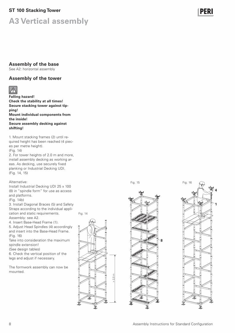
Assembly of the tower
Falling hazard!Check the stability at all times!Secure stacking tower against tip-ping!Mount individual components from the inside!Secure assembly decking against shifting!
1. Mount stacking frames (2) until re-
quired height has been reached (4 piec-
es per metre height).
(Fig. 14)
2. For tower heights of 2.0 m and more,
install assembly decking as working ar-
eas. As decking, use securely fixed
planking or Industrial Decking UDI.
(Fig. 14, 15)
Alternative:
Install Industrial Decking UDI 25 x 100
(8) in “spindle form” for use as access
and platforms.
(Fig. 14b)
3. Install Diagonal Braces (5) and Safety
Straps according to the individual appli-
cation and static requirements.
Assembly: see A2.
4. Insert Base-Head Frame (1).
5. Adjust Head Spindles (4) accordingly
and insert into the Base-Head Frame.
(Fig. 16)
Take into consideration the maximum
spindle extension!
(See design tables)
6. Check the vertical position of the
legs and adjust if necessary.
The formwork assembly can now be
mounted.
ST 100 Stacking Tower
Fig. 14
Fig. 15 Fig. 16
m
8
> 2
,0
6
6
9Assembly Instructions for Standard Configuration
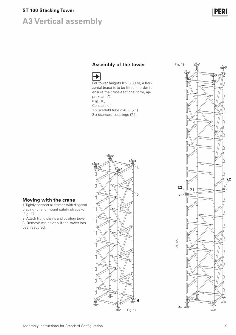
A3 Vertical assembly
Assembly of the tower
For tower heights h > 8.30 m, a hori-
zontal brace is to be fitted in order to
ensure the cross-sectional form, ap-
prox. at h/2.
(Fig. 18)
Consists of:
1 x scaffold tube ø 48.3 (7.1)
2 x standard couplings (7.2).
ST 100 Stacking Tower
ca.
Fig. 18
Fig. 17
Moving with the crane1. Tightly connect all frames with diagonal
bracing (5) and mount safety straps (6).
(Fig. 17)
2. Attach lifting chains and position tower.
3. Remove chains only if the tower has
been secured.
7.1
7.2
7.2
h/2
5

10
A4 Dismantling
Assembly Instructions for Standard Configuration
Ensure stability during dismantling!
The tower can be dismantled in either a
vertical or horizontal position.
Dismantling vertically1. Lower the stacking tower.
2. Remove formwork assembly.
3. Dismantle tower from top to bottom.
Remove diagonal bracing only if the sta-
bility is guaranteed.
(Fig. 19)
Dismantling horizontally1. Move out stacking tower from under
the concreted slab.
2. Attach lifting chains and lower stack-
ing tower onto a flat surface.
3. Dismantle stacking tower.
If structural diagonal bracing has been
mounted, it is recommended to lower
the stacking tower via the head spin-
dles.
ST 100 Stacking Tower
Concreted slab
Fig. 19
11Assembly Instructions for Standard Configuration
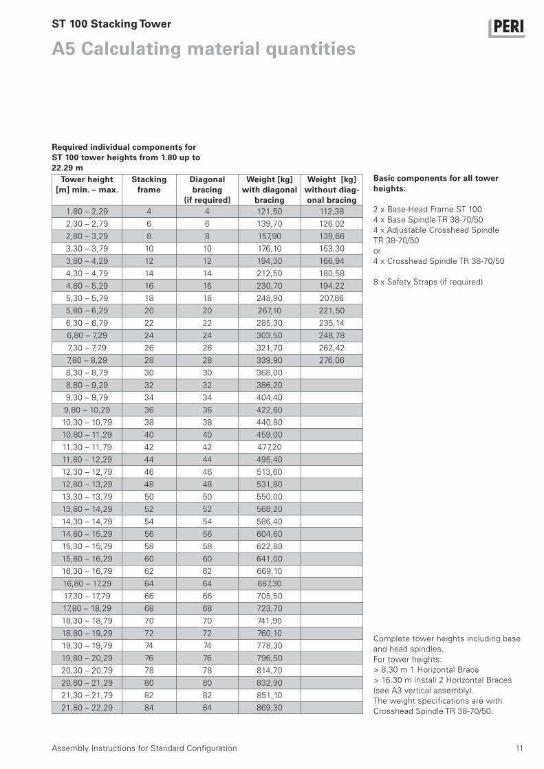
A5 Calculating material quantitiesST 100 Stacking Tower
1,80 – 2,29 4 4 121,50 112,38
2,30 – 2,79 6 6 139,70 126,02
2,80 – 3,29 8 8 157,90 139,66
3,30 – 3,79 10 10 176,10 153,30
3,80 – 4,29 12 12 194,30 166,94
4,30 – 4,79 14 14 212,50 180,58
4,80 – 5,29 16 16 230,70 194,22
5,30 – 5,79 18 18 248,90 207,86
5,80 – 6,29 20 20 267,10 221,50
6,30 – 6,79 22 22 285,30 235,14
6,80 – 7,29 24 24 303,50 248,78
7,30 – 7,79 26 26 321,70 262,42
7,80 – 8,29 28 28 339,90 276,06
8,30 – 8,79 30 30 368,00
8,80 – 9,29 32 32 386,20
9,30 – 9,79 34 34 404,40
9,80 – 10,29 36 36 422,60
10,30 – 10,79 38 38 440,80
10,80 – 11,29 40 40 459,00
11,30 – 11,79 42 42 477,20
11,80 – 12,29 44 44 495,40
12,30 – 12,79 46 46 513,60
12,80 – 13,29 48 48 531,80
13,30 – 13,79 50 50 550,00
13,80 – 14,29 52 52 568,20
14,30 – 14,79 54 54 586,40
14,80 – 15,29 56 56 604,60
15,30 – 15,79 58 58 622,80
15,80 – 16,29 60 60 641,00
16,30 – 16,79 62 62 669,10
16,80 – 17,29 64 64 687,30
17,30 – 17,79 66 66 705,50
17,80 – 18,29 68 68 723,70
18,30 – 18,79 70 70 741,90
18,80 – 19,29 72 72 760,10
19,30 – 19,79 74 74 778,30
19,80 – 20,29 76 76 796,50
20,30 – 20,79 78 78 814,70
20,80 – 21,29 80 80 832,90
21,30 – 21,79 82 82 851,10
21,80 – 22,29 84 84 869,30
Required individual components for ST 100 tower heights from 1.80 up to 22.29 m
Basic components for all tower heights:
2 x Base-Head Frame ST 100
4 x Base Spindle TR 38-70/50
4 x Adjustable Crosshead Spindle
TR 38-70/50
or
4 x Crosshead Spindle TR 38-70/50
8 x Safety Straps (if required)
Tower height [m] min. – max.
Stacking frame
Diagonal bracing
(if required)
Weight [kg] with diagonal
bracing
Weight [kg] without diag-onal bracing
Complete tower heights including base
and head spindles.
For tower heights:
> 8.30 m 1 Horizontal Brace
> 16.30 m install 2 Horizontal Braces
(see A3 vertical assembly).
The weight specifications are with
Crosshead Spindle TR 38-70/50.

12
Free standing, with Pivoting Head Spindle
48.4permissible usable resistance
μ = 0.2
FH [kN]
FV [kN]
Win
d o
n t
he
Tow
er
H ≤
5.2
9 m
Pivoting Head Spindle
TR 38 - 70 / 50
sK ≤
34
0s
F ≤
30
0
Base Spindle
TR 38 - 70 / 50
FV
FH
FV
FH
60.0
50.0
40.0
30.0
20.0
10.0
0.10 0.20 0.30 0.40 0.50 0.60
53.0
3.14.1
42.9
21.8
17.6
Win
d o
n t
he
Tow
er
H ≤
7.2
9 m
FV
FH
FV
FH
47.7permissible usable resistance
μ = 0.4
FH [kN]
FV [kN]60.0
50.0
40.0
30.0
20.0
10.0
0.10 0.20 0.30 0.40 0.50 0.60
52.6
5.36.6
40.9
30.3
24.5
min. load against sliding
μ = 0.4
min. load against sliding
μ = 0.2
Perm. Leg Load
sK ≤
34
0s
F ≤
30
0
Application Conditions (D1)– free standing
– with wind
– with diagonal bracing
– H ≤ 5.29 m
Pivoting Head Spindle
TR 38 - 70 / 50
Base Spindle
TR 38 - 70 / 50
Perm. Leg Load
Application Conditions (D2)– free standing
– with wind
– with diagonal bracing
– H ≤ 7.29m
Type Test
No. II B 3-543-236
ST 100 Stacking Tower

13
–
51.6
52.6
48.5
54.0
50.0
48.0
52.0
53.8 53.5 53.5
5.0 6.0 7.0 8.0 9.0 10.0 11.0 12.0 13.0
5.2
9
8.2
9
12
.29
50.0
48.0
46.0
44.0
52.0
50.8
5.0
5.2
9
8.2
96.0 7.0 8.0 9.0
47.7
48.9
44.1
Win
d o
n t
he
Tow
er
H ≤
8.2
9 m
FVFV
Restrained at the Top,with Pivoting Head Spindle
without wind
H [m]
FV [kN]
H ≤ 5.29 m: H 5.29 m – 8.29 m: H 8.29 m – 12.29 m:s
K ≤
34
0s
F ≤
30
0
FVFV
FV
FV
FVFV
FV
FV
FVFV
FV
FV
Type Test
No. II B 3-543-236
Perm. Leg Load
Application Conditions (D3)– restrained at the top
– with/without wind
H ≤ 5.29 m
1 diagonal brace at the top and bottom
5.29 m < H ≤ 8.29 m
2 diagonal braces at the top and bottom
8.29 m < H ≤ 12.29 m
3 diagonal braces at the top and bottom
plus horizontal cross strut at H/2
Pivoting Head Spindle
TR 38 - 70 / 50
Base Spindle
TR 38 - 70 / 50
Perm. Leg Load
Application Conditions (D4)– restrained at the top
– without diagonal bracing
– with/without wind
– H ≤ 8.29 m
1 diagonal brace at
the top and bottom.
2 diagonal braces at
the top and bottom.
3 diagonal braces at
the top and bottom.
Plus horizontal
cross strut at H/2.
with wind
H [m]
FV [kN]
with wind
without wind
53.5 kN / Legwithout wind
48.5 kN / Legwith wind
53.5 kN / Legwithout wind
51.6 kN / Legwith wind
53.8 kN / Legwithout wind
52.6 kN / Legwith wind
ST 100 Stacking Tower

14
Free standing, with Pivoting Head Spindle
48.4permissible usable resistance
μ = 0.2
FH [kN]
FV [kN]
Win
d o
n t
he
Tow
er
H ≤
5.2
9 m
Pivoting Head Spindle
TR 38 - 70 / 50
sK ≤
34
0s
F ≤
30
0
Base Spindle
TR 38 - 70 / 50
FV
FH
FV
FH
60.0
50.0
40.0
30.0
20.0
10.0
0.10 0.20 0.30 0.40 0.50 0.60
53.0
3.14.1
42.9
21.8
17.6
Win
d o
n t
he
Tow
er
H ≤
7.2
9 m
FV
FH
FV
FH
47.7permissible usable resistance
μ = 0.4
FH [kN]
FV [kN]60.0
50.0
40.0
30.0
20.0
10.0
0.10 0.20 0.30 0.40 0.50 0.60
52.6
5.36.6
40.9
30.3
24.5
min. load against sliding
μ = 0.4
min. load against sliding
μ = 0.2
Perm. Leg Load
sK ≤
34
0s
F ≤
30
0
Application Conditions (D1)– free standing
– with wind
– with diagonal bracing
– H ≤ 5.29 m
Pivoting Head Spindle
TR 38 - 70 / 50
Base Spindle
TR 38 - 70 / 50
Perm. Leg Load
Application Conditions (D2)– free standing
– with wind
– with diagonal bracing
– H ≤ 7.29 m
Type Test
No. II B 3-543-236
ST 100 Stacking Tower

15
–
51.6
52.6
48.5
54.0
50.0
48.0
52.0
53.8 53.5 53.5
5.0 6.0 7.0 8.0 9.0 10.0 11.0 12.0 13.0
5.2
9
8.2
9
12
.29
50.0
48.0
46.0
44.0
52.0
50.8
5.0
5.2
9
8.2
96.0 7.0 8.0 9.0
47.7
48.9
44.1
Win
d o
n t
he
Tow
er
H ≤
8.2
9 m
FVFV
Restrained at the Top,with Pivoting Head Spindle
without wind
H [m]
FV [kN]
H ≤ 5.29 m: H 5.29 m – 8.29 m: H 8.29 m – 12.29 m:s
K ≤
34
0s
F ≤
30
0
FVFV
FV
FV
FVFV
FV
FV
FVFV
FV
FV
Type Test
No. II B 3-543-236
Perm. Leg Load
Application Conditions (D3)– restrained at the top
– with/without wind
H ≤ 5.29 m
1 diagonal brace at the top and bottom
5.29 m < H ≤ 8.29 m
2 diagonal braces at the top and bottom
8.29 m < H ≤ 12.29 m
3 diagonal braces at the top and bottom
plus horizontal cross strut at H/2
Pivoting Head Spindle
TR 38 - 70 / 50
Base Spindle
TR 38 - 70 / 50
Perm. Leg Load
Application Conditions (D4)– restrained at the top
– without diagonal bracing
– with/without wind
– H ≤ 8.29 m
1 diagonal brace at
the top and bottom.
2 diagonal braces at
the top and bottom.
3 diagonal braces at
the top and bottom.
Plus horizontal
cross strut at H/2.
with wind
H [m]
FV [kN]
with wind
without wind
53.5 kN / Legwithout wind
48.5 kN / Legwith wind
53.5 kN / Legwithout wind
51.6 kN / Legwith wind
53.8 kN / Legwithout wind
52.6 kN / Legwith wind
ST 100 Stacking Tower
16
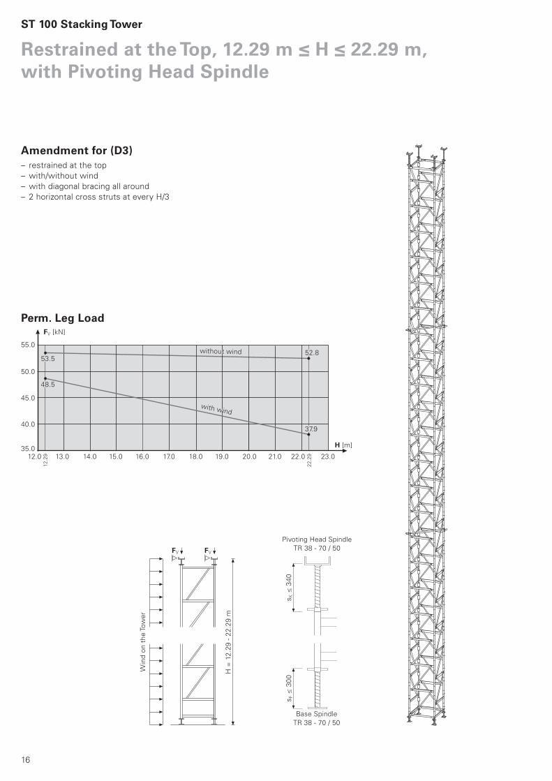
Restrained at the Top, 12.29 m ≤ H ≤ 22.29 m, with Pivoting Head Spindle
H [m]
FV [kN]
50.0
40.0
35.0
45.0
53.552.8
with wind
48.5
12.0
12
.29
22
.29
sK ≤
34
0s
F ≤
30
0
55.0
13.0 14.0 15.0 16.0 17.0 18.0 19.0 20.0 21.0 22.0 23.0
37.9
without wind
Win
d o
n t
he
Tow
er
H =
12
.29
- 2
2.2
9 m
FVFV
Perm. Leg Load
Amendment for (D3)– restrained at the top
– with/without wind
– with diagonal bracing all around
– 2 horizontal cross struts at every H/3
Pivoting Head Spindle
TR 38 - 70 / 50
Base Spindle
TR 38 - 70 / 50
ST 100 Stacking Tower
17
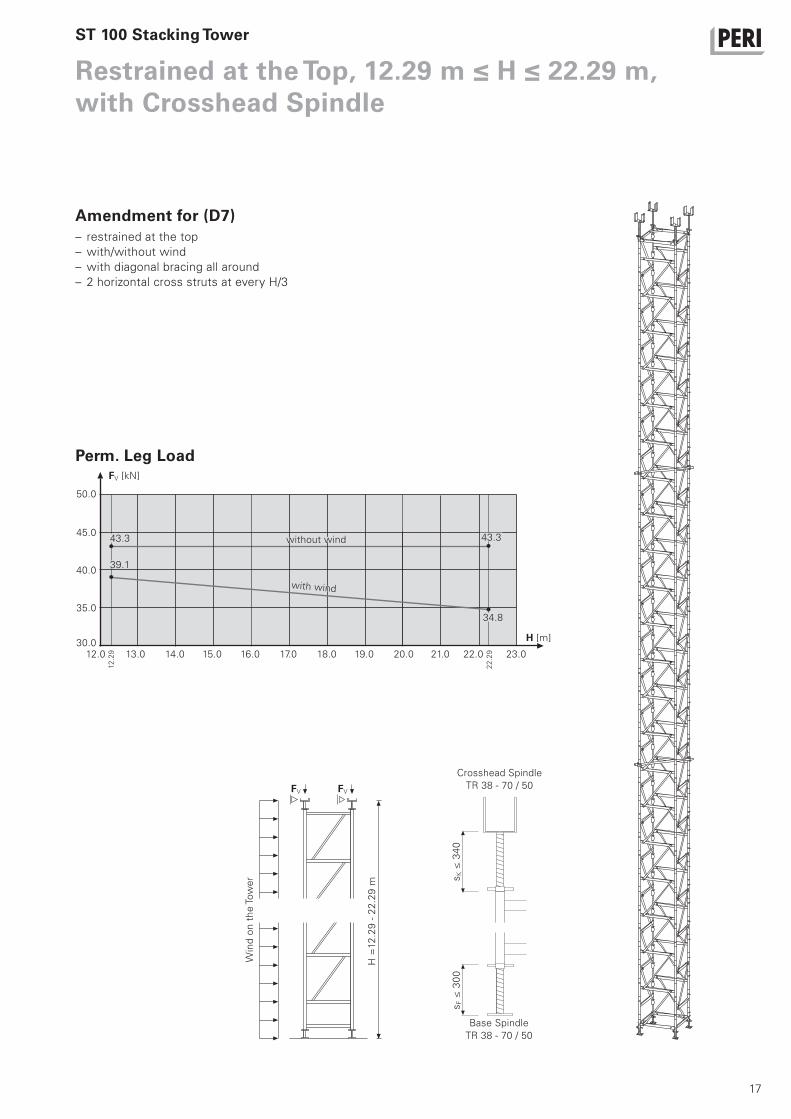
Restrained at the Top, 12.29 m ≤ H ≤ 22.29 m, with Crosshead Spindle
sK ≤
34
0s
F ≤
30
0
without wind
H [m]
FV [kN]
45.0
35.0
30.0
40.0
43.3
34.8
43.3
with wind
39.1
12.0
12
.29
22
.29
50.0
13.0 14.0 15.0 16.0 17.0 18.0 19.0 20.0 21.0 22.0 23.0
H =
12
.29
- 2
2.2
9 m
Win
d o
n t
he
Tow
er
FVFV
Perm. Leg Load
Amendment for (D7)– restrained at the top
– with/without wind
– with diagonal bracing all around
– 2 horizontal cross struts at every H/3
Crosshead Spindle
TR 38 - 70 / 50
Base Spindle
TR 38 - 70 / 50
ST 100 Stacking Tower

18
Item no. Weight kg
ST 100 Stacking Tower
019900 16,600 Base Frame ST 100, galv.Base- and Headframe for ST 100 Stacking Tower.
450
125 12580
330
Ø48,3
Ø22
1000
1000
019910 6,820 Stacking Frame ST 100, galv.Stacking frame for St100.
4 required per metre rise.25
0
250
12512573
8
1000
Ø22
Ø48,3
500
019940 2,290 Diagonal Brace ST 100, galv.Diagonal for ST 100. The number required depends
on the static system.
1250
1300
Ø34

19
Item no. Weight kg
ST 100 Stacking Tower
019780 5,160 Base Spindle TR 38-70/50For more heavily loaded shoring.
With captive swivel nut.
535
min
47m
ax 710
38
80
140
Ø14
Ø21
Ø19
Ø10
110
019790 6,360 Pivoting Head Spindle TR 38-70/50Head plate tilting in any direction by 4.4°.
With captive swivel nut.
3853
5m
in51
max
717
50
170 85 37,537,5
80
190
Ø19
Ø13
110
160 Ø10
Ø21
Ø14
019950 7,690 Crosshead Spindle Tr 38-70/50Head spindle providing stable support for one or
two GT 24 or VT 20 girders.
With captive swivel nut.
535
min
47m
ax
195
710
Ø6,5
85 155
170
240
38

20
Item no. Weight kg
ST 100 Stacking Tower
019800 0,063 Safety Strap Spindle ST 100To secure spindles into the frames when moving
with the crane.
154
71Ø
019920 6,180 End Waler ST 100, galv.To brace the End Frames ST100. 2 per end waler
level.
62 208
1000
90
019930 5,260 End Frame ST 100, galv.To be used instead of the Base Frame ST100. In
combination with End Waler ST 100.
2 per end waler level.
125 125
1000
25033
0
80
450
Ø22
Ø48,3
019810 1,010 Connector ST 100, galv.For connecting additional legs to the ST 100.
Required where heavy point loads are to be sup-
ported. 2 per additional frame and metre rise.
250 30
112
307
Ø10

21
Item no. Weight kg
ST 100 Stacking Tower
106092 6,960 Industrial Deck UDI 25 x 100 X perm. p [kN/m²]1000 10,0
96
1000
6024
5
065050 124,000 Pallet ST 100-2, galv.For stacking and transportation of ST 100 Stacking
Tower components. Capacity:
84 Stacking Frames + Base- and Head Spindles +
Diagonal Braces.
Safety InstructionLoad carrying capacity 1.0 t.
Follow Instruction for Use!
700
970
2280
2400
900
1020
300
400
026411
026412
026413
026414
026419
026418
026415
026417
3,550
7,100
10,650
14,200
17,750
21,600
3,550
,000
Scaffold Tube Steel Ø 48,3 x 3,2Scaffold Tube Steel Ø 48,3 x 3,2, l = 1,0 mScaffold Tube Steel Ø 48,3 x 3,2, l = 2,0 mScaffold Tube Steel Ø 48,3 x 3,2, l = 3,0 mScaffold Tube Steel Ø 48,3 x 3,2, l = 4,0 mScaffold Tube Steel Ø 48,3 x 3,2, l = 5,0 mScaffold Tube Steel Ø 48,3 x 3,2, l = 6,0 mScaffold Tube Steel Ø 48,3 x 3,2, Special LengthCutting Costs Scaffold Tubes
L1000
2000
3000
4000
5000
6000
Ø48,3x3,2L

22
Item no. Weight kg
ST 100 Stacking Tower
017020 1,120 Standard Coupling NK 48/48, galv.For scaffold tubes Ø 48 mm.
NoteSpanner size SW 19.
SW 19
9
017010 1,400 Swivel Coupling DK 48/48, galv.For scaffold tubes Ø 48 mm.
NoteSpanner size SW 19.
SW 19
27


26
02PERI S.A.S.
Zone Industrielle Nord
34-36 rue des Frères Lumière
77109 Meaux [email protected]
www.peri.fr
03PERI AG
Aspstraße 17
8472 [email protected]
www.peri.ch
04PERI S.A. Sociedad
Unipersonal
Ctra. Paracuellos -
Fuente el Saz km. 18,9
Cno. de Malatones, km. 0,5
28110 Algete/[email protected]
www.peri.es
05N.V. PERI S.A.
Industriepark
Nijverheidsstraat 6 PB 54
1840 [email protected]
www.peri.be
06PERI B.V.
v. Leeuwenhoekweg 23
Postbus 304
5480 [email protected]
www.peri.nl
07PERI Formwork Systems, Inc.
7135 Dorsey Run Road
Elkridge, MD [email protected]
www.peri-usa.com
08PT Beton Perkasa Wijaksana
P.O. Box 3737
Jakarta [email protected]
www.peri.de
09PERI S.p.A.
Via G. Pascoli, 4
20060 Basiano (MI)[email protected]
www.peri.it
10PERI Japan K.K.
7F Hakozaki 314 Building,
31-4 Hakozaki-cho,
Nihonbashi Chuo-ku
Tokyo [email protected]
www.perijapan.jp
11PERI Ltd.
Market Harborough Road
Clifton upon Dunsmore
Rugby, CV23 [email protected]
www.peri.ltd.uk
12PERI Kalıp ve İskeleleri
San. ve Tic. Ltd. Sti.
Çakmaklı Mahallesi
Akçaburgaz Cad.
72. Sokak No: 23
Kıraç - Büyükçekmece/Istanbul [email protected]
www.peri.com.tr
13PERI Kft.
Zádor u. 4.
1181 [email protected]
www.peri.hu
14PERI Formwork Malaysia
Sdn. Bhd.
Unit 19-07-4, Level 7
PNB Damansara
19 Lorong Dungun
Damansara Heights
50490 Kuala [email protected]
www.perimalaysia.com
15PERI ASIA Pte. Ltd
Formwork Pte. Ltd.
No. 1 Sims Lane # 06-10
Singapore [email protected]
www.periasia.com
16PERI Ges.mbH
Traisenstraße 3
3134 Nußdorf ob der [email protected]
www.peri.at
17PERI spol. s r.o.
Průmyslová 392
252 42 [email protected]
www.peri.cz
18PERI Danmark A/S
forskalling og stillads
Greve Main 26
2670 [email protected]
www.peri.dk
19PERI Suomi Ltd. Oy
Hakakalliontie 5
05460 Hyvinkää[email protected]
www.perisuomi.fi
20PERI NORGE AS
Dråpen 9
3036 [email protected]
www.peri.no
21PERI Polska Sp. z o.o.
ul. Stołeczna 62
05-860 Pł[email protected]
www.peri.pl.pl
22PERIform SVERIGE AB
Montörgatan 4-6
Box 9073
30013 [email protected]
www.periform.se
23PERI (Korea) Ltd.
8-9th Fl., Yuseong Bldg.
830-67, Yeoksam-dong,
Kangnam-ku,
Seoul [email protected]
www.perikorea.com
24PERIcofragens Lda.
Cofragens e Andaimes
Rua Cesário Verde,
nº 5 - 3º Esq.
Linda-a-Pastora2790-326 [email protected]
www.peri.pt
25PERI S.A.
Ruta Nacional N°. 9, km 47,5
(Panamericana Ramal Escobar)
(1625) Escobar/Prov. Bs. [email protected]
www.peri.com.ar
26PERI Formas e
Escoramentos Ltda.
Rodovia Raposo Tavares,
km 41
Colinas Bandeirante
CEP 06730-000Vargem Grande PaulistaSão [email protected]
www.peribrasil.com.br
27PERI Chile Ltda.
C/José de San Martin N° 104
Parque Industrial Los
Libertadores
Colina, Santiago de [email protected]
www.peri.cl
28PERI România SRL
Calea Bucureşti nr. 2B
077015 Baloteşti - [email protected]
www.peri.ro
29PERI SLOWENIEN
Goran Opalic
Obrežna 137
2000 [email protected]
www.peri.de
30PERI spol. s r.o.
Šamorínska 18
903 01 [email protected]
www.peri.sk
31PERI Australia Pty. Ltd.
116 Glendenning Road
Glendenning NSW [email protected]
www.periaus.com.au
32PERI AS
Valdmäe 8
Tänassilma Tehnopark
76401 Saku valdHarjumaa
www.peri.ee
2
1
3
4
5
6
9
11
12
1316
17
18
19
20
22
21
24
2829
30
32
33
34
38
41
42
46
48
52
53
61
01 PERI GmbHRudolf-Diesel-Strasse
89264 Weissenhorn
www.peri.com
France
Switzerland
Spain
Belgium/Luxembourg
Netherlands
USA
Indonesia
Italy
Japan
United Kingdom/Ireland
Turkey
Hungary
Malaysia
Singapore
Austria
Czech Republic
Denmark
Finland
Norway
Poland
Sweden
Korea
Portugal
Argentina
Brazil
Chile
Romania
Slovania
Slovakia
Australia
Estonia
PERI International

27
33PERI Hellas Ltd.
Sokratous Str.
5th kil. Koropi-Varis Ave.
P. O. Box 407
194 00 [email protected]
www.perihellas.gr
34PERI SIA
Granita 26
1057 [email protected]
www.peri-latvija.lv
35PERI (L.L.C.)
Brashy Building,
Office No. 212
Shk. Zayed Road
P.O. Box 27933
www.perime.com
36PERI Formwork Systems, Inc.
45 Nixon Road
Bolton, OntarioL7E [email protected]
www.peri.ca
37PERI GmbH
Lebanon Representative
Office
AYA Commercial Center,
7th floor,
Dora Highway,
BeirutP.O. Box 90 416 Jdeidet
www.peri.de
38PERI UAB
Titnago st. 19
02300 [email protected]
www.peri.lt
39PERI S.A.
Route de Rabat, km. 5
Piste de Beni Touzine
www.peri.de
40PERI Formwork
Engineering Ltd
16 Moshe Dayan st.,
P.O. Box 10202
Petach Tikva,
49002 [email protected]
www.peri.co.il
41PERI BULGARIA EOOD
Kv. Vragdebna
m. Nova Machala Nr. 46
1839 – [email protected]
www.peri.bg
42MEST ltd.,
Fornubudum 5
www.mest.is
43TOO PERI Kazakhstan
Rubenstein Street 10
(Corner Dostyk Str. 7)
050010 [email protected]
www.peri.kz
44OOO PERI
8 Etage, OOO PERI Buro
Krasnaya Presnya Str. 24
123022 [email protected]
www.peri.ru
45PERI Wiehahn (Pty.) Ltd.
P.O. Box 2668
Bellville [email protected]
www.periwiehahn.co.za
46TOW PERI Ukraina
23, M. Raskowa Str., B. 822
02002 [email protected]
www.peri.ua
47PERI GmbH
Egypt Branch Office
24 A, Obour Gardens,
4th Floor, apt. # 1
Salah Salem Street
11361 [email protected]
www.peri.com.eg
48PERI Oplate d.o.o.
Jurija Gagarina 81
11070 Novi [email protected]
www.peri.co.yu
49PERI Cimbras y Andamios,
S.A. de C.V.
Parque de las Américas
KM 3.5 Carretera
Jorobas – Tula
Huehuetoca
Estado de México,C.P. [email protected]
www.peri.com.mx
50PERI Kalıp ve İskeleleri
Baku Branch Office
28 May Küç. Ev 72 Menzil 27
www.peri.com.tr
51PERI Kalıp ve İskeleleri
Aşgabat Branch Office
Göroglu Sokak No. 130, Kat 2
744035 Aş[email protected]
www.peri.com.tr
52PERI Belarus
Pr. Nesawisimosti 11
Kopus-2 Zimmer: 526,528
220030 [email protected]
www.peri.com.tr
53PERI oplate i skele d.o.o.
Dolenica 20
10 250 Donji Stupnik/[email protected]
www.peri.com.hr
54PERI GmbH
Iran Branch Office
Flat 27, 5th floor, KAVE BLVD,
Building No. 4
P.O. Box 1939793669
www.peri.ir
55PERI (India) Pvt Ltd
717 Palm Springs
Palm Court
Malad Link Road
Malad (West)
Mumbai – [email protected]
www.peri.in
56PERI Jordan
Saad 5 Center, 4th Floor
Office No. 404
Al Madineh
Al Munawara Street
P.O. Box 367
11947 [email protected]
www.peri.de
57PERI Kuwait
Arraya Center, 29th Floor
Al-Shuhada Street, Sharq
P.O. Box 1060 Safat
13011 [email protected]
www.peri.de
58PERI Saudi Arabia
33 AL-Batraa Street
AL -Shurbatiy Building
AL - Bughdadiah AL -
Gharbiah Distrect
6th Floor, Flat # 61
P.O. Box 11641
www.peri.de
59PERI Qatar LLC
P.O. Box 24133
www.peri.de
60Société PERI S.A.S.
Bureau de liaison d‘Alger
50 bis, Route de Gué
de Constantine
Hai El Badr (ex Apreval)
Immeuble FADLI
Kouba - [email protected]
www.peri.fr
61Autostrada TIRANE-DURRES
Km 2 Rr dytesore
ne krah te Vodafonit
Perballe ARDENOS FUSHE -
MEZES TIRANE
Tirane / [email protected]
www.peri.com.tr
62Av. Defensores
del Morro 2074
Chorrillos
Lima
7
8
10
1415
23
25
26
27 31
35
36
3739 40
43
44
45
4749
50 51
54
595558
5760 56
62
Greece
Latvia
United Arab Emirates
Canada
Libanon
Lithuania
Marocco
Israel
Bulgaria
Iceland
Kazakhstan
Russian Federation
South Africa
Ukraine
Egypt
Serbia
Mexico
Azerbaijan
Turkmenistan
Belorussia
Croatia
Iran
India
Jordan
Kuwait
Saudi Arabia
Qatar
Algeria
Albania
Peru
D e
02
/20
09
5m
a A
rt.
Nr.
: 7
918
36
©
Co
pyri
gh
t by P
ER
I G
mb
H
Wall FormworkPanel Formwork
Girder Formwork
Circular Formwork
Facade Formwork
Brace Frame
Column FormworkSquare
Rectangular
Circular
Slab FormworkPanel Formwork
Beam Grid Formwork
Girder Formwork
Slab Table
Beam Formwork
Shoring SystemsSteel Slab Props
Aluminium Slab Props
Tower Systems
Heavy-Duty Props
Climbing SystemsClimbing Scaffold
Self-Climbing System
Climbing Protection Panel
Platform Systems
Scaffold, Stairways, Working PlatformsFacade Scaffold
Working Platform
Weather Protection Roof
Stairway Access
Bridge and Tunnel FormworkCantilevered Parapet Carriage
Cantilevered Parapet Platform
Engineer’s Construction Kit
ServicesFormwork Assembly
Cleaning / Repairs
Formwork Planning
Software
Statics
Special Constructions
Additional Systems
Plywood
Formwork Girders
Stopend Systems
Pallets
Transportation Containers
PERI GmbHFormwork Scaffolding EngineeringP.O. Box 1264
89259 Weissenhorn
Germany
Tel +49 (0)73 09.9 50- 0
Fax +49 (0)73 09.9 51- 0
www.peri.com
PERI Product Range