Embed Size (px)
Citation preview
ST 3000 Smart Transmitter Release 300 with HART Communications Option
(HART 5 and HART 6 Versions)
User Manual
Doc. No.: 34-ST-25-17
Revision Date: February 2012
Honeywell Process Solutions
Notices and Trademarks
ii ST 3000 HART Transmitter Release 300 User Manual February 2012
Notices and Trademarks
Copyright 2011 by Honeywell Inc. February 2012
While this information is presented in good faith and believed to be accurate, Honeywell disclaims the implied warranties of merchantability and fitness for a particular purpose and makes no express warranties except as may
be stated in its written agreement with and for its customers.
In no event is Honeywell liable to anyone for any indirect, special or consequential damages. The information and specifications in this document are subject to change without notice.
Honeywell is a U.S. registered trademarks Of Honeywell Inc.
"HART is a registered trademark of the HART Communications Foundation"
Other brand or product names are trademarks of their respective owners.
Honeywell Process Solutions
1860 West Rose Garden Lane
Phoenix, Arizona 85027
Patent Notice
This product is covered by one or more of the following U.S. Patents: 4,520,488; 4,567,466; 4,494,183; 4,502,335; 4,592,002; 4,553,104; 4,541,282; 4,806,905; 4,797,669; 4,735,090; 4,768,382; 4,787,250; 4,888,992; 5,811,690; 5,875,150; 5,765,436; 4,734,873; 6,041,659 and other patents pending.
Patent Notice - Before You Begin, Please Note
About This Document
Contact Info
World Wide Web
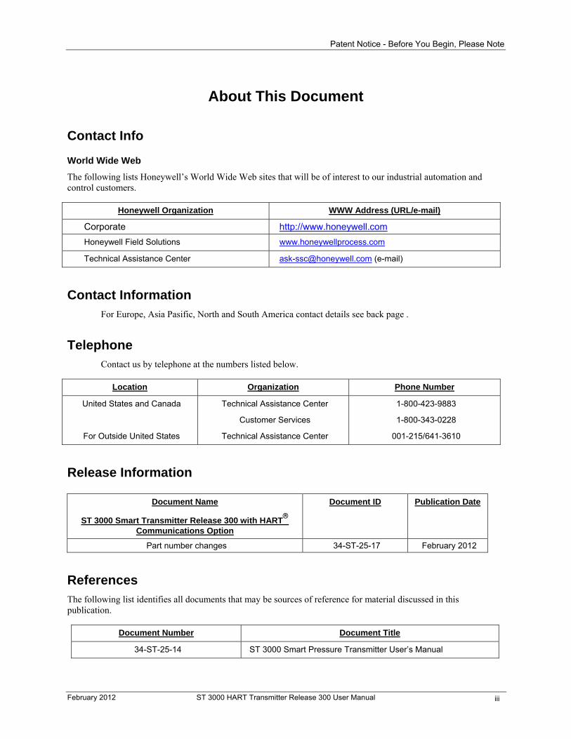
The following lists Honeywell’s World Wide Web sites that will be of interest to our industrial automation and control customers.
Honeywell Organization WWW Address (URL/e-mail)
Corporate http://www.honeywell.com
Honeywell Field Solutions www.honeywellprocess.com
Technical Assistance Center [email protected] (e-mail)
Contact Information For Europe, Asia Pasific, North and South America contact details see back page .
Telephone Contact us by telephone at the numbers listed below.
Location Organization Phone Number
United States and Canada
For Outside United States
Technical Assistance Center
Customer Services
Technical Assistance Center
1-800-423-9883
1-800-343-0228
001-215/641-3610
Release Information
Document Name
ST 3000 Smart Transmitter Release 300 with HART
Communications Option
Document ID Publication Date
Part number changes 34-ST-25-17 February 2012
References The following list identifies all documents that may be sources of reference for material discussed in this publication.
Document Number Document Title
34-ST-25-14 ST 3000 Smart Pressure Transmitter User’s Manual
February 2012 ST 3000 HART Transmitter Release 300 User Manual iii
Patent Notice - Before You Begin, Please Note
Technical Assistance If you encounter a problem with your ST 3000 Smart Transmitter, check to see how your transmitter is currently configured to verify that all selections are consistent with your application.
If the problem persists, you can reach Honeywell’s Solution Support Center for technical support by telephone during normal business hours. An engineer will discuss your problem with you. Please have your complete model number, serial number, and software revision number on hand for reference. You can find the model and serial numbers on the transmitter nameplates. You may also seek additional help by contacting the Honeywell distributor who supplied your ST 3000 transmitter.
Problem Resolution
If it is determined that a hardware problem exists, a replacement transmitter or part will be shipped with instructions for returning the defective unit. Please do not return your transmitter without authorization from Honeywell’s Solution Support Center or until the replacement has been received.
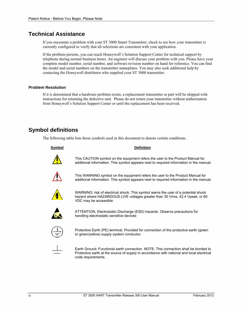
Symbol definitions The following table lists those symbols used in this document to denote certain conditions.
Symbol Definition
This CAUTION symbol on the equipment refers the user to the Product Manual for additional information. This symbol appears next to required information in the manual.
This WARNING symbol on the equipment refers the user to the Product Manual for additional information. This symbol appears next to required information in the manual.
WARNING: risk of electrical shock. This symbol warns the user of a potential shock hazard where HAZARDOUS LIVE voltages greater than 30 Vrms, 42.4 Vpeak, or 60 VDC may be accessible.
ATTENTION, Electrostatic Discharge (ESD) hazards. Observe precautions for handling electrostatic sensitive devices
Protective Earth (PE) terminal. Provided for connection of the protective earth (green or green/yellow) supply system conductor.
Earth Ground. Functional earth connection. NOTE: This connection shall be bonded to Protective earth at the source of supply in accordance with national and local electrical code requirements.
ST 3000 HART Transmitter Release 300 User Manual February 2012 iv
Patent Notice - Before You Begin, Please Note
Contents
Patent Notice.............................................................................................................. ii Problem Resolution......................................................................................................................... iv
Before You Begin, Please Note........................................................................................................ xvi Transmitter Terminal Blocks ......................................................................................................... xvi
Preface....................................................................................................................xvii
1— Introduction - First Time Users Only ....................................................................1
Overview..............................................................................................................................................1 About this section.............................................................................................................................1 Section contents ..............................................................................................................................1 Glossary of terms and abbreviations: ..............................................................................................1
ST 3000 Smart Transmitters ...............................................................................................................2 About the transmitter........................................................................................................................2 Functional block diagram.................................................................................................................3 Series and model number data........................................................................................................4 ST 3000 transmitter family...............................................................................................................5
HART Communicator ........................................................................................................................7 Transmitter adjustments ..................................................................................................................7 Transmitter operator interface .........................................................................................................7 HART 5 or HART 6? ....................................................................................................................7 The HART Communicator Purpose ...............................................................................................7
Transmitter Order ................................................................................................................................8 Order components ...........................................................................................................................8 About documentation.......................................................................................................................8
Local Smart Meter Option ...................................................................................................................9 Smart meter assembly .....................................................................................................................9 Option availability...........................................................................................................................10
2— Quick Start Reference .......................................................................................11
Overview............................................................................................................................................11 About this section...........................................................................................................................11
Getting ST 3000 Transmitter On-Line Quickly ..................................................................................12 Quick start-up tasks .......................................................................................................................12
3— Preinstallation Considerations ...........................................................................13
Overview............................................................................................................................................13 About this section...........................................................................................................................13
Safety Integrity Level (SIL) ................................................................................................................13
CE Conformity (Europe) Notice.........................................................................................................13 About conformity and special conditions .......................................................................................13
February 2012 ST 3000 HART Transmitter Release 300 User Manual v
Patent Notice - Before You Begin, Please Note
Considerations for ST 3000 Transmitter ...........................................................................................14 Evaluate conditions........................................................................................................................14 Temperature limits .........................................................................................................................14 Pressure ratings.............................................................................................................................16
Considerations for HART communicator.........................................................................................16 Guidelines ......................................................................................................................................16
Considerations for Local Smart Meter Option ...................................................................................16
4— Installation .........................................................................................................17
Overview............................................................................................................................................17 About this section...........................................................................................................................17
Mounting ST 3000 Transmitter..........................................................................................................17 Summary........................................................................................................................................17 Dimensions ....................................................................................................................................17 Bracket mounting ...........................................................................................................................18 Mounting Transmitters with Small Absolute or Differential Pressure Spans .................................20 Flange mounting ............................................................................................................................23 Flush mounting ..............................................................................................................................24 High Temperature Transmitter Mounting.......................................................................................26 Remote seal mounting...................................................................................................................28
Piping ST 3000 Transmitter...............................................................................................................30 Piping Arrangements .....................................................................................................................30 Transmitter location .......................................................................................................................31 Process connections......................................................................................................................32 Flange descriptions........................................................................................................................33 General piping guidelines ..............................................................................................................33 Installing flange adapter.................................................................................................................34
Wiring ST 3000 Transmitter ..............................................................................................................35 Summary........................................................................................................................................35 Wiring connections.........................................................................................................................36 Approval body requirements..........................................................................................................37 Lightning protection........................................................................................................................38 Process Sealing .............................................................................................................................38 Explosionproof Conduit seal ..........................................................................................................38 Output meter options .....................................................................................................................39
5— Getting Started...................................................................................................41
Overview............................................................................................................................................41 About this section...........................................................................................................................41
Establishing Communications ...........................................................................................................41 Software compatibility ....................................................................................................................41 Upgrading HART communicator software ...................................................................................42 Connecting the communicator .......................................................................................................43 Starting communications................................................................................................................44
Making Initial Checks.........................................................................................................................45 Checking configuration data ..........................................................................................................45 Transmitter write protection option ................................................................................................46 Failure mode (Failsafe) alarm jumper............................................................................................46 Local smart meter display indications............................................................................................47
ST 3000 HART Transmitter Release 300 User Manual February 2012 vi
Patent Notice - Before You Begin, Please Note
6— Configuration .....................................................................................................48
Overview............................................................................................................................................48 About this section...........................................................................................................................48 Section contents ............................................................................................................................48
Configuration Overview .....................................................................................................................49 About configuration ........................................................................................................................49 Communicator and ST 3000 transmitter memories.......................................................................49 Copying transmitter configuration into nonvolatile memory...........................................................50 What to configure...........................................................................................................................51 Interface menus .............................................................................................................................52 Model 275 Communicator..............................................................................................................58 Model 275 Interface characteristics ...............................................................................................59 Symbols .........................................................................................................................................59 Model 375 Communicator..............................................................................................................60 Model 375 Interface characteristics ...............................................................................................61 Making changes with 275 Communicator......................................................................................62 Making changes with Model 375 Communicator...........................................................................63
Tag— Entering a Tag Number ..........................................................................................................64
PV unit— Selecting Unit of Pressure Measurement .........................................................................65
Range Values— Setting PV URV and PV LRV.................................................................................66 Procedure for keying in LRV and URV ..........................................................................................66 Procedure for setting range values to applied pressure ................................................................67
Device Information.............................................................................................................................68 Output form options .......................................................................................................................70 About square root output ...............................................................................................................70 Square root dropout .......................................................................................................................71
PV damping— Adjusting Damping Time...........................................................................................72
SV units— Selecting Secondary Variable units ................................................................................73
Poll addr— Selecting Poll Address....................................................................................................74
Install Date – Enter Install Date.........................................................................................................75
Disconnecting the Communicator .....................................................................................................75 Disconnection checklist..................................................................................................................75
7— Start-up..............................................................................................................76
Overview............................................................................................................................................76 About this section...........................................................................................................................76
Start-up Tasks ...................................................................................................................................77 About start-up ................................................................................................................................77 Procedure reference ......................................................................................................................77
Running Analog Output .....................................................................................................................78 Background....................................................................................................................................78 Procedure ......................................................................................................................................78
Flow Measurement with DP Transmitter ...........................................................................................80 Procedure ......................................................................................................................................80
Pressure Measurement with DP Transmitter ....................................................................................82 Procedure ......................................................................................................................................82
February 2012 ST 3000 HART Transmitter Release 300 User Manual vii
Patent Notice - Before You Begin, Please Note
Liquid Level Measurement – Vented Tank........................................................................................85 Procedure ......................................................................................................................................85
Liquid Level Measurement – Pressurized Tank ................................................................................87 Procedure ......................................................................................................................................87
Pressure or Liquid Level Measurement with GP Transmitter............................................................90 Procedure ......................................................................................................................................90
Pressure Measurement with AP........................................................................................................93 Procedure ......................................................................................................................................93
Liquid Level Measurement with DP Transmitter with Remote Seals ................................................96 Procedure ......................................................................................................................................96
8— Operation.........................................................................................................101
Introduction......................................................................................................................................101 About this section.........................................................................................................................101
Accessing Operation Data...............................................................................................................101 Summary......................................................................................................................................101
Changing Default Failsafe Direction and Write Protect Jumpers....................................................105 Default failsafe direction...............................................................................................................105 Write protect option......................................................................................................................105 Procedure ....................................................................................................................................105
Writing Data in the Message Area...................................................................................................108
Saving and Restoring a Configuration Database ............................................................................109 Background..................................................................................................................................109 Procedures...................................................................................................................................110
9-Advanced Diagnostics for ST 3000 Release.......................................................112
Introduction......................................................................................................................................112 About this section.........................................................................................................................112
Diagnostics/Service - Advanced Diagnostics..................................................................................112 Power Up Diagnostics..................................................................................................................112 Electronics Temperature Tracking Diagnostics ...........................................................................113 Operating Voltage Diagnostics ....................................................................................................115 PV Tracking Diagnostics..............................................................................................................116 Meter Body Temperature Tracking Diagnostics ..........................................................................118 Static Pressure Tracking Diagnostics ..........................................................................................119
Calibration Records .........................................................................................................................120 Zero Trim Records .......................................................................................................................120 Correct LRV Records...................................................................................................................121 Correct URV Records ..................................................................................................................121
Process Variables Parameters........................................................................................................122 Electronics Temperature..............................................................................................................122 Static Pressure.............................................................................................................................122
Basic Setup – Device Info ...............................................................................................................123 Install Date ...................................................................................................................................123 Model Number .............................................................................................................................123 Materials of Construction .............................................................................................................123
ST 3000 HART Transmitter Release 300 User Manual February 2012 viii
Patent Notice - Before You Begin, Please Note
Review Parameters .........................................................................................................................124 Install Date ...................................................................................................................................124 Power fail count ...........................................................................................................................124 Electronics Temperature..............................................................................................................124 % Service Life in Stress...............................................................................................................125 % Service Life Used.....................................................................................................................125 Static Pressure.............................................................................................................................126
10— Maintenance ..................................................................................................127
Introduction......................................................................................................................................127 About this section.........................................................................................................................127
Preventive Maintenance..................................................................................................................127 Maintenance routines and schedules ..........................................................................................127
Inspecting and Cleaning Barrier Diaphragms .................................................................................127 Procedure ....................................................................................................................................127
Replacing Printed Wiring Assembly (PWA).....................................................................................130 About the PWA Electronics Board ...............................................................................................130
Replacing Meter Body .....................................................................................................................133
11— Calibration .....................................................................................................137
Introduction......................................................................................................................................137 About this section.........................................................................................................................137
Overview..........................................................................................................................................137 About calibration ..........................................................................................................................137
Calibrating Analog Output Signal ....................................................................................................138
Calibrating Range............................................................................................................................139
Resetting Calibration .......................................................................................................................142 Background..................................................................................................................................142 Procedure ....................................................................................................................................142
12 - Diag/Service – Advanced Diagnostics ............................................................143
Introduction......................................................................................................................................143 About this section.........................................................................................................................143
Overview..........................................................................................................................................143 About Advanced Diagnostics.......................................................................................................143
13— Troubleshooting .............................................................................................145
Introduction......................................................................................................................................145 About this section.........................................................................................................................145
Troubleshooting Overview...............................................................................................................145 Diagnostics ..................................................................................................................................145 Troubleshooting tool ....................................................................................................................145
To access transmitter diagnostics ...................................................................................................145
February 2012 ST 3000 HART Transmitter Release 300 User Manual ix
Patent Notice - Before You Begin, Please Note
Diagnostic Messages ......................................................................................................................146 Summary......................................................................................................................................146 Critical failures .............................................................................................................................146 Non-critical failures ......................................................................................................................147 Communication errors..................................................................................................................148
Interpreting Messages.....................................................................................................................149
Clearing Critical Status....................................................................................................................151
14— Parts List........................................................................................................152
Replacement Parts ..........................................................................................................................152 About this section.........................................................................................................................152
14— Reference Drawings ......................................................................................173
Wiring Diagrams ..............................................................................................................................173 Contents.......................................................................................................................................173
Appendix A— Smart Meter Reference ...................................................................175
Introduction......................................................................................................................................175 About this section.........................................................................................................................175 Smart meter option ......................................................................................................................176 Smart Meter Set up......................................................................................................................176
Smart Meter Display ........................................................................................................................177 Display description.......................................................................................................................177
Smart Meter Specifications .............................................................................................................179 Operating conditions and specifications ......................................................................................179 Meter Display at High and Low Temperature Extremes..............................................................179
Setting Range Values (Local Zero and Span).................................................................................180 Local zero and span option..........................................................................................................180 About local adjustments...............................................................................................................180
Configuring Smart Meter Using Pushbuttons..................................................................................183 Using the Smart Meter .................................................................................................................183 Transmitter Output Conformity and Smart Meter Configuration..................................................184 Selecting Engineering Units.........................................................................................................185 Setting Lower and Upper Display Values ....................................................................................187 Setting Lower Display Values ......................................................................................................188 Setting Upper Display Values ......................................................................................................191
Setting smart meter display using the HART communicator.........................................................196 Using the Hart Communicator to Configure the Smart Meter Display.........................................196 Transmitter Output Conformity and Smart Meter Configuration..................................................196
Typical smart meter indications.......................................................................................................199
Operation error codes......................................................................................................................200
Meter/transmitter interaction............................................................................................................201 Transmitter power cycling............................................................................................................201 Changing output conformity.........................................................................................................201
ST 3000 HART Transmitter Release 300 User Manual February 2012 x
Patent Notice - Before You Begin, Please Note
Appendix B— Configuration Record Sheet ............................................................203
ST 3000 R300 Smart Transmitter with HART Communications ...................................................203
Appendix C – Freeze Protection of Transmitters....................................................205 Problem........................................................................................................................................205
Possible Solutions/Methods ............................................................................................................205 Solution ........................................................................................................................................205 Sealing liquid method...................................................................................................................205 Purging.........................................................................................................................................207 Gas applications ..........................................................................................................................207 Mechanical (diaphragm) seals.....................................................................................................207 Electric heating ............................................................................................................................209 Steam heating..............................................................................................................................210 Superheated steam considerations .............................................................................................213
Appendix D —Hazardous Area Classifications ......................................................215
Introduction......................................................................................................................................215 Reference information..................................................................................................................215
North American Hazardous Location Standards.............................................................................215 NEC and CEC electrical codes....................................................................................................215 Classes ........................................................................................................................................215 Divisions.......................................................................................................................................215 Examples .....................................................................................................................................215 Group classifications....................................................................................................................216 Methods of protection ..................................................................................................................216 Temperature classification...........................................................................................................217 Intrinsically safe apparatus parameters .......................................................................................217 Associated apparatus parameters ...............................................................................................218 Entity concept ..............................................................................................................................218
International Electrotechnical Commission (IEC) Classifications....................................................220 IEC Classification of hazardous locations....................................................................................220 Zones ...........................................................................................................................................220 Groups .........................................................................................................................................220 Methods of protection ..................................................................................................................221 Temperature classification...........................................................................................................221 Certification and conformity details..............................................................................................222
Enclosure Ratings ...........................................................................................................................224 NEMA and IEC Recognition ........................................................................................................224 IEC Classifications .......................................................................................................................224 IEC Designations .........................................................................................................................224 NEMA Standards .........................................................................................................................224
Process Sealing for Classes I, II, and III, Divisions 1 and 2 and Class I, Zone 0, 1, and 2, Explosionproof Electrical Systems ..................................................................................................225
ST 3000, Smart Pressure Transmitters .......................................................................................225
Index ......................................................................................................................227
February 2012 ST 3000 HART Transmitter Release 300 User Manual xi
Patent Notice - Before You Begin, Please Note
Tables
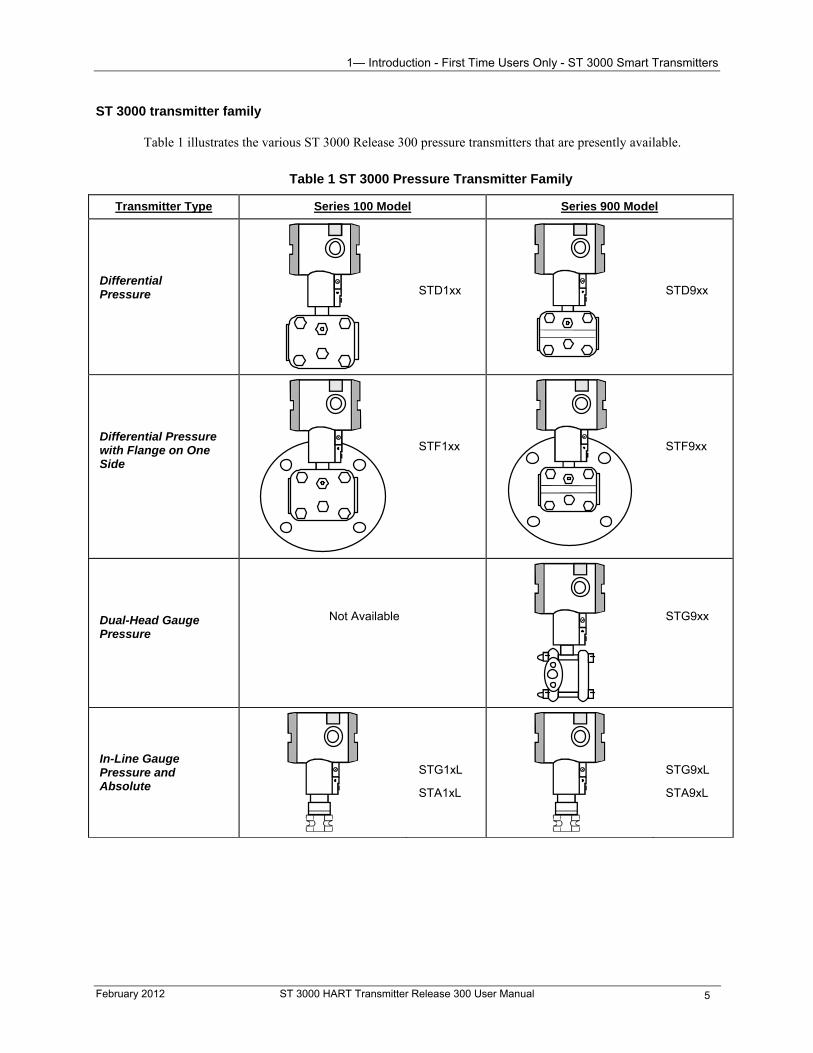
Table 1 ST 3000 Pressure Transmitter Family ..............................................................................................................5 Table 2 Local Smart Meter Options ............................................................................................................................10 Table 3 Start-up Tasks Reference................................................................................................................................12 Table 4 Operating Temperature Limits (Transmitters with Silicone Fill Fluid DC200) .............................................15 Table 5 Transmitter Maximum Allowable Working Pressure (MAWP) Ratings........................................................16 Table 6 Mounting ST 3000 Transmitter to a Bracket ..................................................................................................18 Table 7 Zero Corrects Procedure for Transmitters with a Small Differential Pressure Span ......................................21 Table 8 Flush Mount Transmitter Installation .............................................................................................................24 Table 9 Mounting Remote Diaphragm Seal Transmitter.............................................................................................28 Table 10 Suggested Transmitter Location for Given Processes ..................................................................................31 Table 11 Process Connections .....................................................................................................................................32 Table 12 Flange Description........................................................................................................................................33 Table 13 Installing Flange Adapter .............................................................................................................................34 Table 14 Wiring the Transmitter .................................................................................................................................37 Table 15 Starting Communications with Transmitter..................................................................................................44 Table 16 Reviewing Factory-Set Configuration Parameters .......................................................................................45 Table 17 Summary of Pressure Transmitter Configuration Parameters ......................................................................51 Table 18 Entering Tag Number ...................................................................................................................................64 Table 19 Selecting Engineering Units .........................................................................................................................65 Table 20 Keying in LRV and URV .............................................................................................................................66 Table 21 Setting LRV and URV to Applied Pressures................................................................................................67 Table 22 Viewing/Entering Device Information Data.................................................................................................68 Table 23 Selecting Output Conformity........................................................................................................................70 Table 24 Adjusting Damping Time .............................................................................................................................72 Table 25 Selecting SV Temperature Units ..................................................................................................................73 Table 26 Selecting Poll Address..................................................................................................................................74 Table 27 Entering Installation Date .............................................................................................................................75 Table 28 Start-up Procedure Reference .......................................................................................................................77 Table 29 Using Transmitter in Constant-Current Source (Output) Mode ...................................................................78 Table 30 Starting Up DP Transmitter for Flow Measurement.....................................................................................80 Table 31 Starting Up DP Transmitter for Pressure Measurement ...............................................................................83 Table 32 Starting Up DP Transmitter for Liquid Level Measurement in Vented Tank...............................................85 Table 33 Starting Up DP Transmitter for Liquid Level Measurement in Pressurized Tank........................................88 Table 34 Starting Up GP Transmitter for Pressure or Liquid Level Measurement .....................................................91 Table 35 Starting Up AP Transmitter for Pressure Measurement. ..............................................................................95 Table 36 Starting Up DP Transmitter with Remote Seals for Liquid Level Measurement .........................................96 Table 37 Summary of Keystrokes for Operation Data Access ..................................................................................102 Table 38 Changing Default Failsafe Direction ..........................................................................................................106 Table 39 Changing Write Protect Jumper..................................................................................................................107 Table 40 Writing Data in the Message Area..............................................................................................................108 Table 41 Saving a Configuration Database ...............................................................................................................110 Table 42 Downloading a Configuration Database.....................................................................................................111 Table 43 Inspecting and Cleaning Barrier Diaphragms.............................................................................................128 Table 44 Process Head Bolt Torque Ratings .............................................................................................................130 Table 45 Replacing PWA ..........................................................................................................................................130 Table 46 Replacing Meter Body Only.......................................................................................................................133 Table 47 Calibrating Output Signal for Transmitter in Analog Mode.......................................................................138 Table 48 Calibrating Measurement Range – Correct LRV........................................................................................139 Table 49 Calibrating Measurement Range – Correct URV .......................................................................................140
ST 3000 HART Transmitter Release 300 User Manual February 2012 xii
Patent Notice - Before You Begin, Please Note
Table 51 View Diagnostics........................................................................................................................................143 Table 52 Summary of Diagnostic Messages for Critical Failures .............................................................................146 Table 53 Summary of Diagnostic Messages for Non-Critical Failures .....................................................................147 Table 54 Summary of Diagnostic Messages for Info Status......................................................................................147 Table 55 Other Error Messages .................................................................................................................................147 Table 56 Summary of Diagnostic Messages for Communication Errors...................................................................148 Table 57 Diagnostic Message Interpretation Table ...................................................................................................149 Table 58 Resetting the Transmitter............................................................................................................................151 Table 59 Major ST 3000 Smart Transmitter Parts Reference....................................................................................154 Table 60 Parts Identification for Callouts in Figure 42 and Figure 43 ......................................................................156 Table 61 Parts Identification for Callouts in Figure 44 and Figure 45. .....................................................................157 Table 62 Parts Identification for Callouts in Figure 44 and Figure 45 ......................................................................160 Table 63 Parts Identification for Callouts in Figure 46. ............................................................................................162 Table 64 Replacement GP and AP Process Head Part Numbers for Narrow Profile Meter Body ...........................163 Table 65 Parts Identification for Callouts in Figure 47. ............................................................................................164 Table 66 Parts Identification for Callouts in Figure 48. ............................................................................................165 Table 67 Parts Identification for Callouts in Figure 49. ............................................................................................166 Table 68 Parts Identification for Callouts in Figure 50. ............................................................................................168 Table 69 Parts Identification for Callouts in Figure 51. ............................................................................................169 Table 70 Summary of Recommended Spare Parts. ...................................................................................................171 Table 71 External Wiring Diagrams..........................................................................................................................173 Table A-1 Description of Smart Meter Display Indicators........................................................................................177 Table A-2 Smart Pushbutton Description..................................................................................................................178 Table A-3 Smart meter specifications. ......................................................................................................................179 Table A-4 Setting Range Values Using Local Zero and Span Adjustments..............................................................180 Table A-5 Smart Meter Engineering Units Code ......................................................................................................184 Table A-6 Selecting Engineering Units .....................................................................................................................185 Table A-7 Setting Lower Display Values for Smart Meter Display..........................................................................188 Table A-8 Setting Upper Display Value for Smart Meter Display............................................................................191 Table A-9 Smart meter display setup using HART communicator .........................................................................197 Table A-10 Summary of Typical Smart Meter Indications. ......................................................................................199 Table A-11 Smart Meter Error Codes and Descriptions............................................................................................200 Table C-1 Temperature Range of Freeze Protection Systems ...................................................................................212 Table C-2 Steam Pressure Versus Steam Temperature Values .................................................................................213 Table D-1 Temperature Identification Numbers (NEC/CEC) ...................................................................................217 Table D-2 FM Entity Parameters...............................................................................................................................219 Table D-3 Temperature Identification Numbers (IEC)..............................................................................................221 Table D-4 NEMA Enclosure Type Numbers and Comparable IEC Enclosure Classification ..................................224
February 2012 ST 3000 HART Transmitter Release 300 User Manual xiii
Patent Notice - Before You Begin, Please Note
Figures
Figure 1 Typical ST 3000 Differential Pressure Transmitter.........................................................................................2 Figure 2 Functional Block Diagram for Transmitter in Analog Mode of Operation. ....................................................3 Figure 3 Typical Communication Interface...................................................................................................................7 Figure 4 Typical ST 3000 Transmitter Order Components. ..........................................................................................8 Figure 5 ST 3000 with Local Smart Meter Option. .......................................................................................................9 Figure 6 Typical Mounting Area Considerations Prior to Installation.........................................................................14 Figure 7 Typical Bracket Mounted and Flange Mounted Installations........................................................................18 Figure 8 Leveling Transmitters ...................................................................................................................................21 Figure 9 Typical Flange Mounted Transmitter Installation .........................................................................................24 Figure 10 Typical Flush Mounted Transmitter Installation .........................................................................................25 Figure 11 Typical Flange and Pipe Mounted Installations ..........................................................................................27 Figure 12 Typical Remote Diaphragm Seal Transmitter Installation. .........................................................................29 Figure 13 Typical 3-Valve Manifold and Blow-Down Piping Arrangement. .............................................................30 Figure 14 Typical Piping Arrangement for ½” NPT Process Connection ...................................................................31 Figure 15 Operating Range for ST 3000 Transmitters. ...............................................................................................35 Figure 16 ST 3000 Transmitter Terminal Blocks ........................................................................................................36 Figure 17 Ground Connection for Lightning Protection..............................................................................................38 Figure 18 Typical Communicator Connections...........................................................................................................43 Figure 19 Write Protection and Failsafe Direction Jumper Location ..........................................................................46 Figure 20 Smart Meter Display with All Indicators Lit...............................................................................................47 Figure 21 Summary of Configuration Process.............................................................................................................49 Figure 22 Communicator and ST 3000 Transmitter Memories ...................................................................................50 Figure 23 HART 5 Online (or HOME) Menu Summary...........................................................................................53 Figure 23a HART 6 Online (or HOME) Menu Summary ...........................................................................................54 Figure 24 HART 6 Online (or HOME) Menu Summary...........................................................................................54 Figure 25 HART 5 275 or 375 Communicator Menu Summary ...............................................................................56 Figure 26 HART 6 375 Communicator Menu Summary ..........................................................................................57 Figure 27 Model 275 HART Communicator.............................................................................................................58 Figure 28 Model 375 HART Communicator.............................................................................................................60 Figure 29 Square Root Dropout Point .........................................................................................................................71 Figure 30 Typical Communicator and Meter Connections for Constant-Current Source (Output) Mode..................79 Figure 31 Typical Piping Arrangement for Flow Measurement with DP Type Transmitter .......................................80 Figure 32 Typical Piping Arrangement for Pressure Measurement with DP Type Transmitter..................................82 Figure 33 Typical Piping Arrangement for Liquid Level Measurement with DP Type Transmitter and Vented Tank85 Figure 34 Typical Piping Arrangement for Liquid Level Measurement with DP Type Transmitter and Pressurized
Tank. 87 Figure 35 Typical Piping Arrangement for Pressure Measurement with GP Type Transmitter..................................90 Figure 36 Typical Piping Arrangement for Liquid Level Measurement with GP Type Transmitter...........................91 Figure 37 Typical Piping Arrangement for Pressure Measurement with AP Type Transmitter..................................94 Figure 38 Typical Piping Arrangement for Liquid Level Measurement with DP Type Transmitter with Remote
Seals.96 Figure 39 Location of Failsafe and Write Protect Jumpers on PWA.........................................................................106 Figure 40 Summary of Save and Restore Database Function....................................................................................109 Figure 41 GP/AP Process Head.................................................................................................................................128 Figure 42 Disassembly of DP Transmitter Process Heads from Meter Body............................................................129 Figure 43 Typical Range Calibration Hookup...........................................................................................................141 Figure 44 Major ST 3000 Smart Transmitter Parts Reference. .................................................................................153 Figure 45 Major ST 3000 Smart Transmitter Parts Reference. .................................................................................154
ST 3000 HART Transmitter Release 300 User Manual February 2012 xiv
Patent Notice - Before You Begin, Please Note
Figure 46 Series 100/900 Electronics Housing - Electronics/Meter End...................................................................155 Figure 47 Series 100/900 Electronics Housing - Terminal Block End......................................................................155 Figure 48 ST 3000 Model STD110, STD120, STD125, STD130, STD170, STD904, STD924, STD930, STD974,
STG944, STG974 (Rev S or greater).................................................................................................................157 Figure 49 ST 3000 Model STG944, STG974 (Rev S or greater) .............................................................................160 Figure 50 Series 100 GP and AP Meter Bodies and Series 900 AP Meter Body ......................................................162 Figure 51 Series 900 Dual-Head GP Meter Bodies. ..................................................................................................164 Figure 52 Series 100 and Series 900 LGP/LAP Meter Body. ...................................................................................165 Figure 53 Series 900 Flush Mount Meter Body.........................................................................................................166 Figure 54 Series 100 and Series 900 Flange Mounted Meter Body. .........................................................................167 Figure 55 High Temperature Meter Body. ................................................................................................................169 Figure A-1 Smart Meter Display with All Indicators Lit...........................................................................................177 Figure A-2 Typical Setup for Setting Range Values Using Local Zero and Span Adjustments................................183 Figure C-1 Piping Installation for Sealing Liquid With Specific Gravity Heavier Than Process Fluid. ..................206 Figure C-2 Piping Installation for Sealing Liquid with Specific Gravity Lighter Than Process Fluid. ....................206 Figure C-3 Piping Installation for Gas Flow..............................................................................................................207 Figure C-4 Piping Installation for Differential Pressure Transmitter with Metal Diaphragm Seals. ........................208 Figure C-5 Piping Installation for Process Pressure Transmitter with Metal Diaphragm Seal.................................208 Figure C-6 Piping Installation for Differential Pressure Transmitter and Impulse Piping with Electric Heating and
Control. ..............................................................................................................................................................209 Figure C-7 Piping Installation for Process Pressure Transmitter and Impulse Piping with Electric Heating Control.210 Figure C-8 Piping Installation for Differential Pressure Transmitter and Impulse Piping with Steam Heating. .......211 Figure C-9 Piping Installation for Process Pressure Transmitter and Impulse Piping with Steam Heating. .............212
February 2012 ST 3000 HART Transmitter Release 300 User Manual xv
Patent Notice - Before You Begin, Please Note
IMPORTANT
Before You Begin, Please Note
Transmitter Terminal Blocks
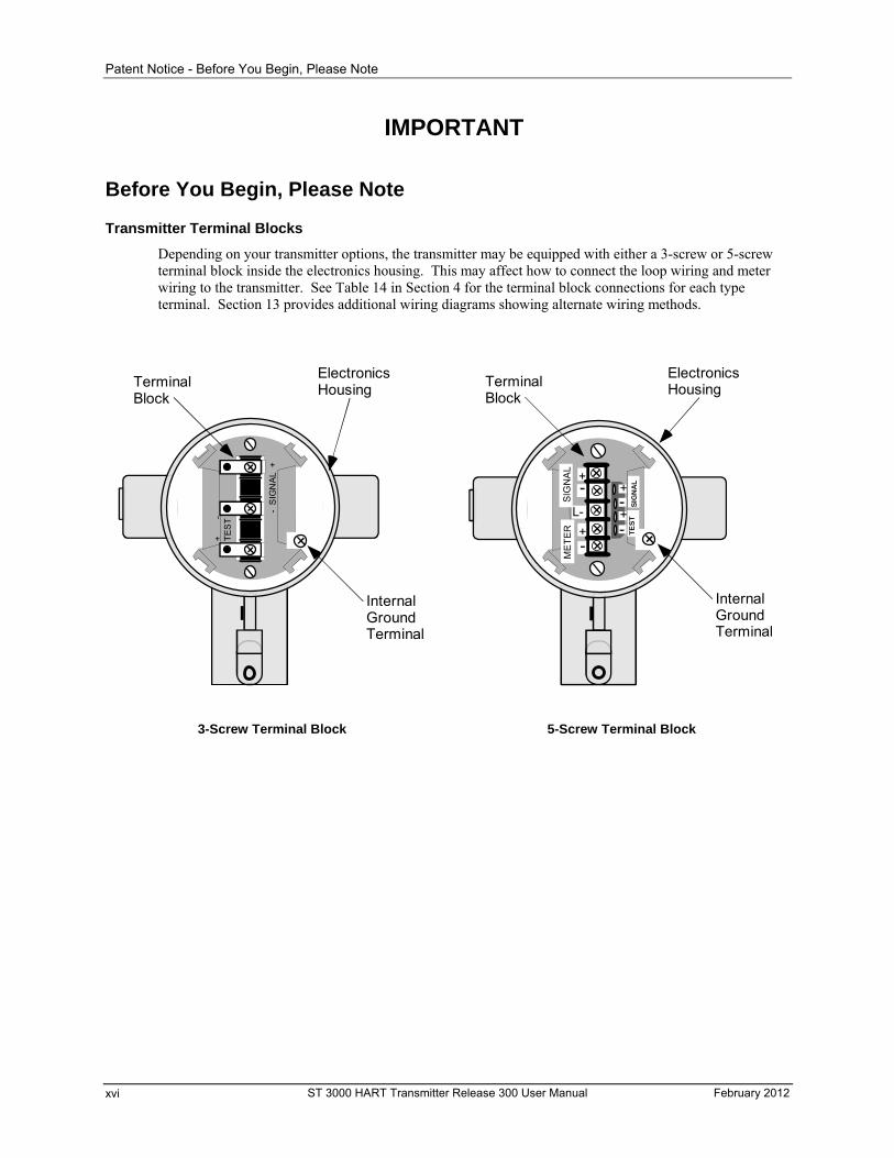
Depending on your transmitter options, the transmitter may be equipped with either a 3-screw or 5-screw terminal block inside the electronics housing. This may affect how to connect the loop wiring and meter wiring to the transmitter. See Table 14 in Section 4 for the terminal block connections for each type terminal. Section 13 provides additional wiring diagrams showing alternate wiring methods.
- S
IGN
AL
+
+
-
TE
ST
TerminalBlock
ElectronicsHousing
InternalGroundTerminal
3-Screw Terminal Block
+
+-
-
L-
SIG
NA
LM
ET
ER TE
ST
SIG
NA
L
-+
+-
TerminalBlock
ElectronicsHousing
InternalGroundTerminal
5-Screw Terminal Block
ST 3000 HART Transmitter Release 300 User Manual February 2012 xvi
Preface - Before You Begin, Please Note
Preface
This preface is included for informational purposes only.
The latest release of the ST 3000 HART
6 Device is known as the “Advanced Diagnostics for ST 3000 Release” with the following Version information:
Universal rev: 6 Field device rev: 5 Software rev: 36
This release will include the Advanced Diagnostics for the ST 3000 HART 6 device.
The advanced diagnostics features will help our customers to:
Reduce maintenance costs.
Know when maintenance is needed.
Know when maintenance was performed.
Know how hard a life the device has had.
Know what to order when a replacement is needed.
There are, in existence, software packages available at the systems level that perform some of these functions but these packages take a lot of effort to set-up and maintain and largely go unused. The advanced diagnostics for the ST 3000 pressure transmitter should be able to provide some of this needed functionality without a lot of user effort.
Listed below are the available Diagnostics in the ST 3000 Transmitter:
Installation Date
Time in Service
Power Cycles
Last Power Up Time and Date
Terminal Voltage
Minimum Terminal Voltage
Minimum Terminal Voltage Date
Status bit indicates less than 10V at terminals
Electronics Temperature Tracking: (Min/Max, timestamp and duration for exceeding limits)
Meter Body Temperature Tracking: (Min/Max, timestamp and duration for exceeding limits)
Process Variable Tracking: (Min/Max, timestamp and duration for exceeding limits)
Static Pressure Tracking: (Max, timestamp and duration for exceeding limits)
Model Number
February 2012 ST 3000 HART Transmitter Release 300 User Manual xvii
-
ST 3000 HART Transmitter Release 300 User Manual February 2012 xviii
Materials of Construction
Stress Monitor
Service Life Expended
Calibration Time and Date
Zero Trim Time and Date
NOTE 1: The features listed above are not available in earlier versions of ST 3000 HART 6 devices or any of the HART 5 Devices.
NOTE 2: Complete list of Advanced Diagnostics with the details is under the section : “Advanced Diagnostics for ST 3000 Release”.
1— Introduction - First Time Users Only - Overview
1— Introduction - First Time Users Only
Overview
About this section
This section is intended for users who have never worked with our ST 3000 Smart Transmitter with HART communications. It provides some general information to acquaint you with the ST 3000 transmitter and the HART communications interface.
Section contents
This section includes these topics:
ST 3000 Smart Transmitters – Brief description of the ST 3000 transmitter form, functions and identification.
HART Communicator – Brief description of the communication interface used with the ST 3000 HART transmitter.
Transmitter order – Describes the components shipped with a transmitter order.
Local Smart Meter Option – Describes the smart meter options available with the transmitter.
Glossary of terms and abbreviations:
ET Electronics Temperature – temperature inside of the electronics housing.
MBT Meter Body Temperature – same as SV or process temperature.
SV Secondary Variable – value is the same as process temperature or meter body temperature.
It is the temperature measured at the pressure sensor.
DP Differential Pressure.
AP Absolute Pressure.
GP Gauge Pressure.
SP Static Pressure same as the pressure on high side.
URV Upper Range Value as selected by end user.
LRV Lower Range Value as selected by end user.
UTL Upper Transducer Limit - Defines the highest acceptable value for the Transducer.
UTL = 2*URL (Units same as PV) for DP where SPAN cannot be greater than UTL
UTL = 1.5*URL (Units same as PV) for AP and GP where SPAN cannot be greater than UTL
LTL Lower Transducer Limit - Defines the lowest acceptable value for the Transducer.
LTL = -2*URL (Unit same as PV) for DP where SPAN cannot be greater than UTL
LTL = 0 (Units same as PV) for AP and GP where SPAN cannot be greater than UTL
URL Upper Sensor Range Limit – Defines the maximum recommended value for the URV.
LRL Lower Sensor Range Limit – Defines the minimum recommended value for the LRV.
February 2012 ST 3000 HART Transmitter Release 300 User Manual 1
1— Introduction - First Time Users Only - ST 3000 Smart Transmitters
ST 3000 Smart Transmitters
About the transmitter
The ST 3000 Smart Transmitter comes in a variety of models for measurement applications involving one of these basic types of pressure:
Differential Pressure
Gauge Pressure
Absolute Pressure
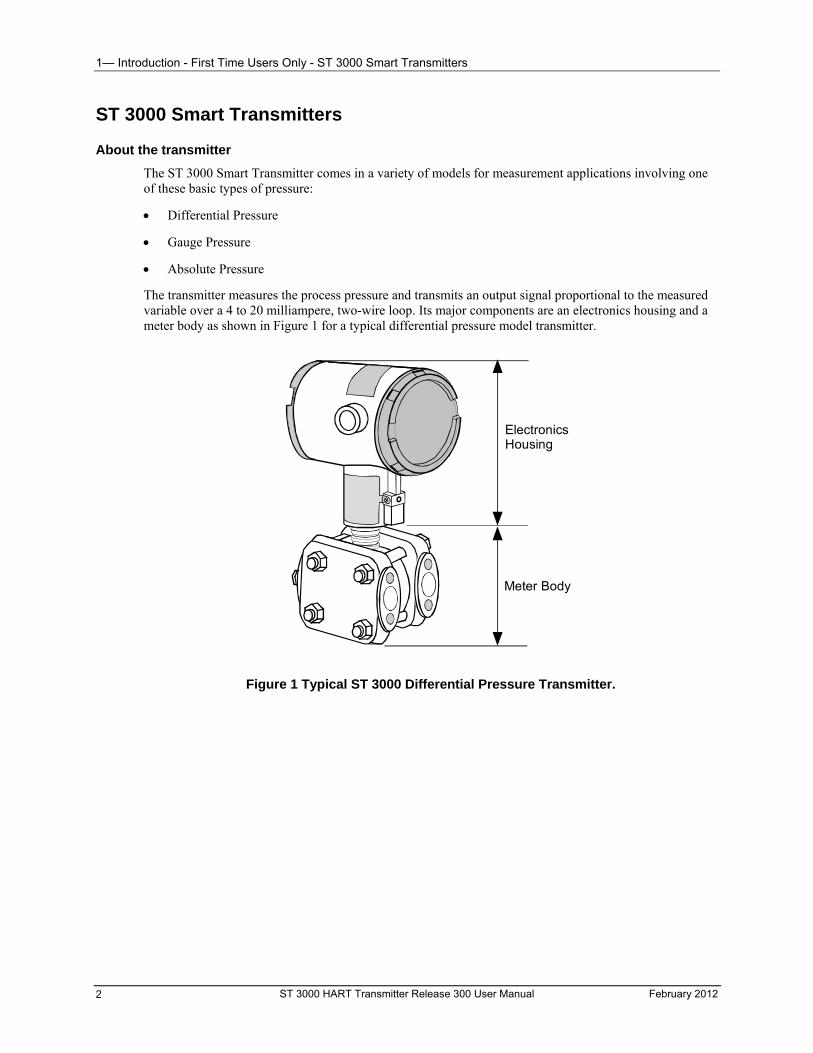
The transmitter measures the process pressure and transmits an output signal proportional to the measured variable over a 4 to 20 milliampere, two-wire loop. Its major components are an electronics housing and a meter body as shown in Figure 1 for a typical differential pressure model transmitter.
ElectronicsHousing
Meter Body
Figure 1 Typical ST 3000 Differential Pressure Transmitter.
ST 3000 HART Transmitter Release 300 User Manual February 2012 2
1— Introduction - First Time Users Only - ST 3000 Smart Transmitters
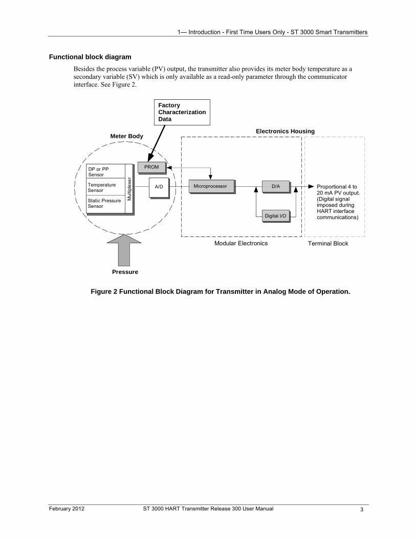
Functional block diagram
Besides the process variable (PV) output, the transmitter also provides its meter body temperature as a secondary variable (SV) which is only available as a read-only parameter through the communicator interface. See Figure 2.
A/D
DP or PPSensor
TemperatureSensor
Static PressureSensor
Meter Body Electronics Housing
Pressure
FactoryCharacterizationData
Modular Electronics Terminal Block
Proportional 4 to20 mA PV output.(Digital signalimposed duringHART interfacecommunications)
D/A
PROM
Mul
tiple
xer
Microprocessor
Digital I/O
Figure 2 Functional Block Diagram for Transmitter in Analog Mode of Operation.
February 2012 ST 3000 HART Transmitter Release 300 User Manual 3
1— Introduction - First Time Users Only - ST 3000 Smart Transmitters
Series and model number data
Honeywell’s line of ST 3000 Smart Transmitters includes these two series designations:
Series 100 Series 900
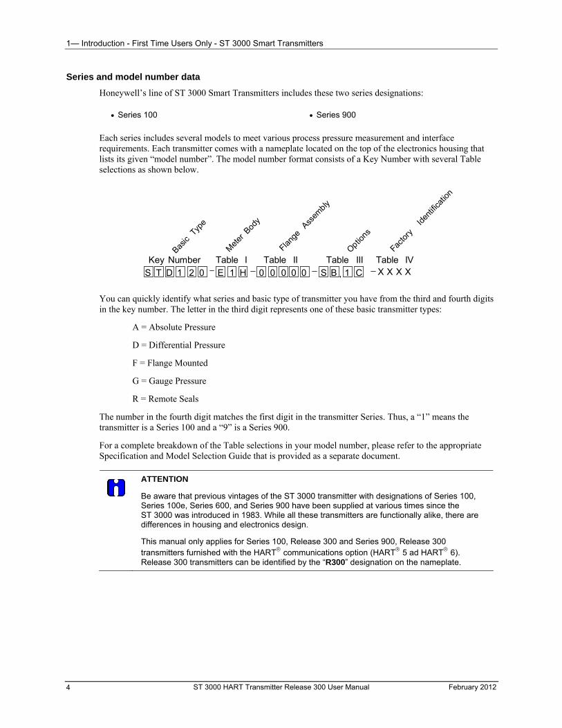
Each series includes several models to meet various process pressure measurement and interface requirements. Each transmitter comes with a nameplate located on the top of the electronics housing that lists its given “model number”. The model number format consists of a Key Number with several Table selections as shown below.
Key Number M
eter
Bod
y
Flang
e Ass
embly
Optio
ns
Factor
y Id
entif
icatio
n
Table I Table II Table III Table IVBas
ic Typ
e
,S T D 1 2 0 E 1 H 0 0 0 0 0 S 1 CB X X X X
You can quickly identify what series and basic type of transmitter you have from the third and fourth digits in the key number. The letter in the third digit represents one of these basic transmitter types:
A = Absolute Pressure
D = Differential Pressure
F = Flange Mounted
G = Gauge Pressure
R = Remote Seals
The number in the fourth digit matches the first digit in the transmitter Series. Thus, a “1” means the transmitter is a Series 100 and a “9” is a Series 900.
For a complete breakdown of the Table selections in your model number, please refer to the appropriate Specification and Model Selection Guide that is provided as a separate document.
ATTENTION
Be aware that previous vintages of the ST 3000 transmitter with designations of Series 100, Series 100e, Series 600, and Series 900 have been supplied at various times since the ST 3000 was introduced in 1983. While all these transmitters are functionally alike, there are differences in housing and electronics design.
This manual only applies for Series 100, Release 300 and Series 900, Release 300 transmitters furnished with the HART communications option (HART 5 ad HART 6). Release 300 transmitters can be identified by the “R300” designation on the nameplate.
ST 3000 HART Transmitter Release 300 User Manual February 2012 4
1— Introduction - First Time Users Only - ST 3000 Smart Transmitters
ST 3000 transmitter family
Table 1 illustrates the various ST 3000 Release 300 pressure transmitters that are presently available.
Table 1 ST 3000 Pressure Transmitter Family
Transmitter Type Series 100 Model Series 900 Model
Differential Pressure
STD1xx
STD9xx
Differential Pressure with Flange on One Side
STF1xx
STF9xx
Dual-Head Gauge Pressure
Not Available
STG9xx
In-Line Gauge Pressure and Absolute
STG1xL
STA1xL
STG9xL
STA9xL
February 2012 ST 3000 HART Transmitter Release 300 User Manual 5
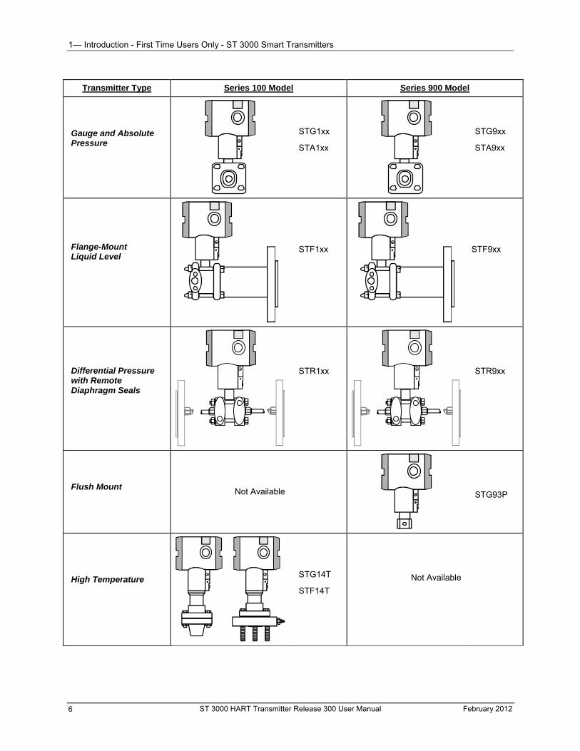
1— Introduction - First Time Users Only - ST 3000 Smart Transmitters
Transmitter Type Series 100 Model Series 900 Model
Gauge and Absolute Pressure
STG1xx
STA1xx
STG9xx
STA9xx
Flange-Mount Liquid Level
STF1xx
STF9xx
Differential Pressure with Remote Diaphragm Seals
STR1xx
STR9xx
Flush Mount
Not Available
STG93P
High Temperature
STG14T
STF14T
Not Available
ST 3000 HART Transmitter Release 300 User Manual February 2012 6
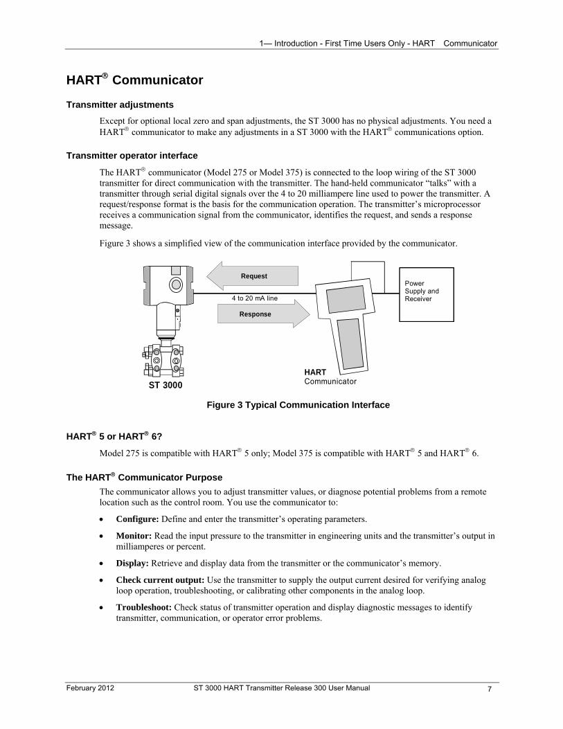
1— Introduction - First Time Users Only - HART Communicator
HART Communicator
Transmitter adjustments
Except for optional local zero and span adjustments, the ST 3000 has no physical adjustments. You need a HART communicator to make any adjustments in a ST 3000 with the HART communications option.
Transmitter operator interface
The HART communicator (Model 275 or Model 375) is connected to the loop wiring of the ST 3000 transmitter for direct communication with the transmitter. The hand-held communicator “talks” with a transmitter through serial digital signals over the 4 to 20 milliampere line used to power the transmitter. A request/response format is the basis for the communication operation. The transmitter’s microprocessor receives a communication signal from the communicator, identifies the request, and sends a response message.
Figure 3 shows a simplified view of the communication interface provided by the communicator.
HARTCommunicator
Request
Response
4 to 20 mA line
ST 3000
PowerSupply andReceiver
Figure 3 Typical Communication Interface
HART 5 or HART 6?
Model 275 is compatible with HART 5 only; Model 375 is compatible with HART 5 and HART 6.
The HART Communicator Purpose
The communicator allows you to adjust transmitter values, or diagnose potential problems from a remote location such as the control room. You use the communicator to:
Configure: Define and enter the transmitter’s operating parameters.
Monitor: Read the input pressure to the transmitter in engineering units and the transmitter’s output in milliamperes or percent.
Display: Retrieve and display data from the transmitter or the communicator’s memory.
Check current output: Use the transmitter to supply the output current desired for verifying analog loop operation, troubleshooting, or calibrating other components in the analog loop.
Troubleshoot: Check status of transmitter operation and display diagnostic messages to identify transmitter, communication, or operator error problems.
February 2012 ST 3000 HART Transmitter Release 300 User Manual 7
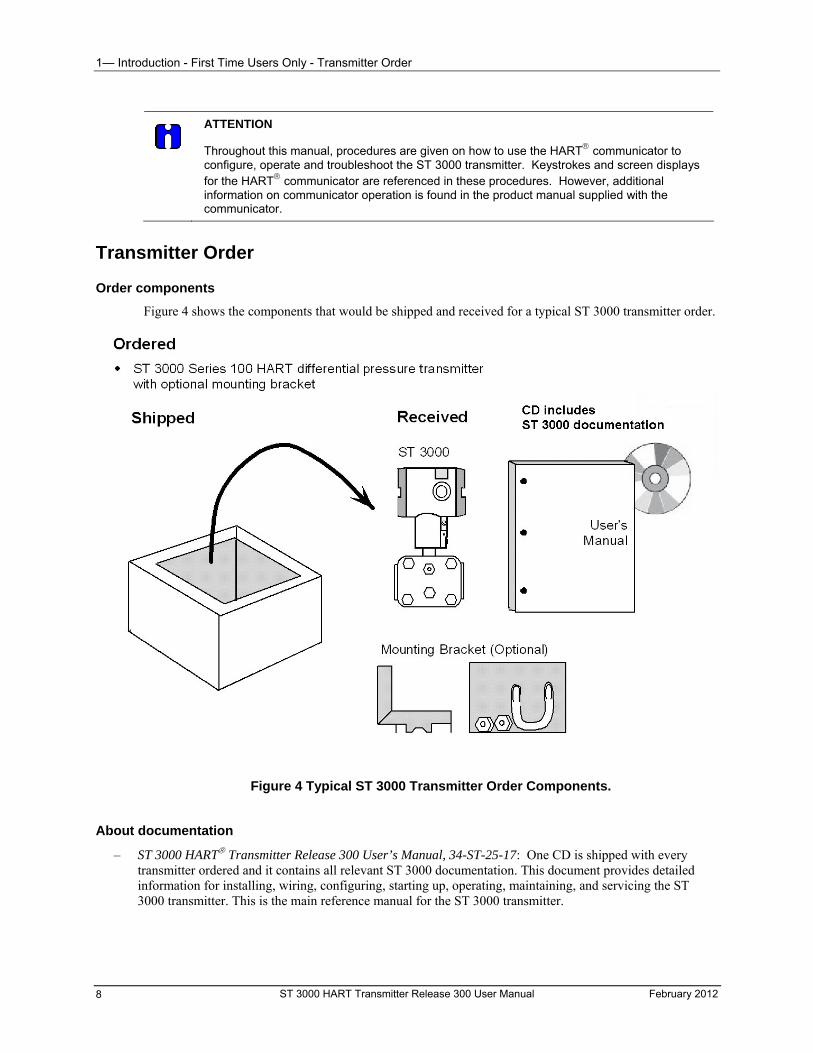
1— Introduction - First Time Users Only - Transmitter Order
ATTENTION
Throughout this manual, procedures are given on how to use the HART communicator to configure, operate and troubleshoot the ST 3000 transmitter. Keystrokes and screen displays for the HART communicator are referenced in these procedures. However, additional information on communicator operation is found in the product manual supplied with the communicator.
Transmitter Order
Order components
Figure 4 shows the components that would be shipped and received for a typical ST 3000 transmitter order.
Figure 4 Typical ST 3000 Transmitter Order Components.
About documentation
– ST 3000 HART Transmitter Release 300 User’s Manual, 34-ST-25-17: One CD is shipped with every transmitter ordered and it contains all relevant ST 3000 documentation. This document provides detailed information for installing, wiring, configuring, starting up, operating, maintaining, and servicing the ST 3000 transmitter. This is the main reference manual for the ST 3000 transmitter.
ST 3000 HART Transmitter Release 300 User Manual February 2012 8
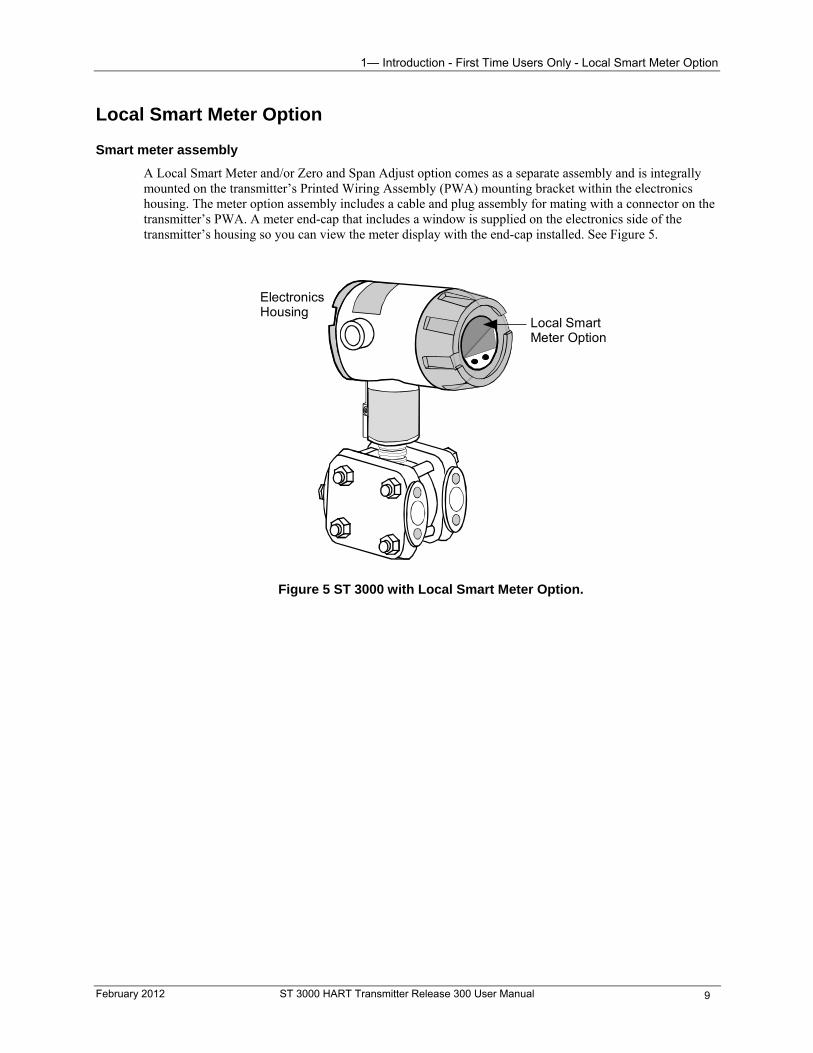
1— Introduction - First Time Users Only - Local Smart Meter Option
Local Smart Meter Option
Smart meter assembly
A Local Smart Meter and/or Zero and Span Adjust option comes as a separate assembly and is integrally mounted on the transmitter’s Printed Wiring Assembly (PWA) mounting bracket within the electronics housing. The meter option assembly includes a cable and plug assembly for mating with a connector on the transmitter’s PWA. A meter end-cap that includes a window is supplied on the electronics side of the transmitter’s housing so you can view the meter display with the end-cap installed. See Figure 5.
ElectronicsHousing
Local SmartMeter Option
Figure 5 ST 3000 with Local Smart Meter Option.
February 2012 ST 3000 HART Transmitter Release 300 User Manual 9
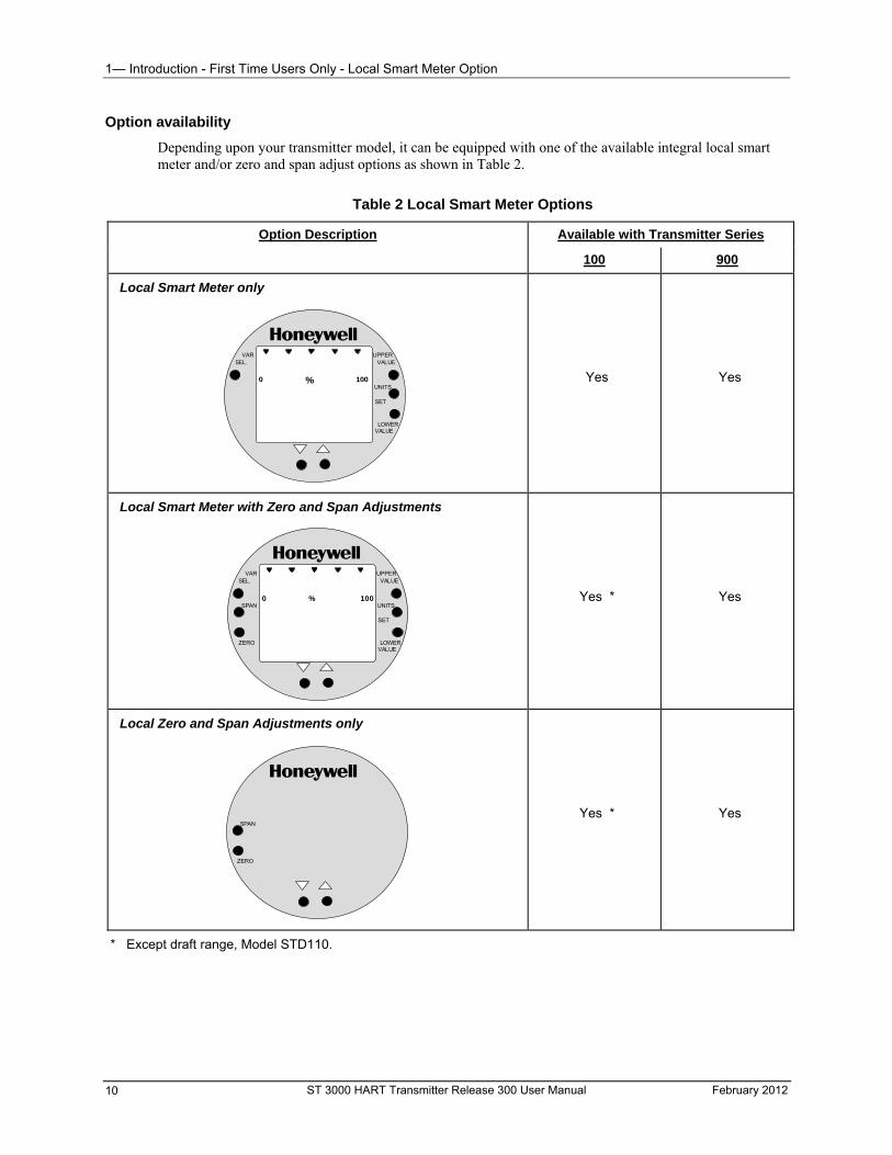
1— Introduction - First Time Users Only - Local Smart Meter Option
Option availability
Depending upon your transmitter model, it can be equipped with one of the available integral local smart meter and/or zero and span adjust options as shown in Table 2.
Table 2 Local Smart Meter Options
Option Description Available with Transmitter Series
100 900
Local Smart Meter only
% 1000
UPPERVALUE
UNITS
LOWERVALUE
SET
VARSEL.
Yes
Yes
Local Smart Meter with Zero and Span Adjustments
% 1000
UPPERVALUE
UNITS
LOWERVALUE
SET
VARSEL.
SPAN
ZERO
Yes *
Yes
Local Zero and Span Adjustments only
SPAN
ZERO
Yes *
Yes
* Except draft range, Model STD110.
ST 3000 HART Transmitter Release 300 User Manual February 2012 10
2— Quick Start Reference - Overview
2— Quick Start Reference
Overview
About this section
This section provides a list of typical start-up tasks and tells you where you can find detailed information about performing the task.
This section assumes that the ST 3000 transmitter has been installed and wired correctly, and is ready to be put into operation. It also assumes that you are somewhat familiar with using the HART communicator and that the transmitter has been configured correctly for your application. If the transmitter has not been installed and wired, you are not familiar with HART communicator operation, and/or you do not know if the transmitter is configured correctly, please read the other sections of this manual before starting up your transmitter.
February 2012 ST 3000 HART Transmitter Release 300 User Manual 11
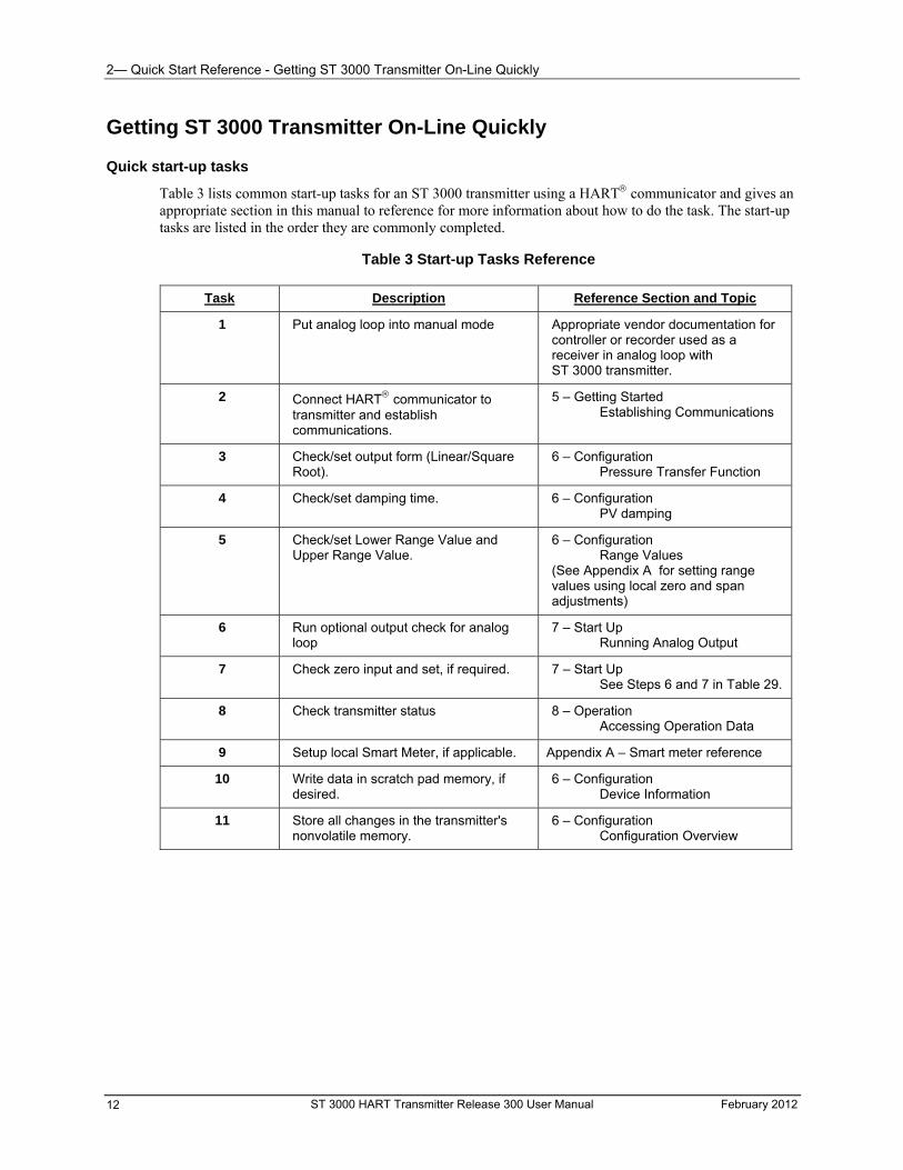
2— Quick Start Reference - Getting ST 3000 Transmitter On-Line Quickly
ST 3000 HART Transmitter Release 300 User Manual February 2012 12
Getting ST 3000 Transmitter On-Line Quickly
Quick start-up tasks
Table 3 lists common start-up tasks for an ST 3000 transmitter using a HART communicator and gives an appropriate section in this manual to reference for more information about how to do the task. The start-up tasks are listed in the order they are commonly completed.
Table 3 Start-up Tasks Reference
Task Description Reference Section and Topic
1 Put analog loop into manual mode Appropriate vendor documentation for controller or recorder used as a receiver in analog loop with ST 3000 transmitter.
2 Connect HART communicator to transmitter and establish communications.
5 – Getting Started Establishing Communications
3 Check/set output form (Linear/Square Root).
6 – Configuration Pressure Transfer Function
4 Check/set damping time. 6 – Configuration PV damping
5 Check/set Lower Range Value and Upper Range Value.
6 – Configuration Range Values (See Appendix A for setting range values using local zero and span adjustments)
6 Run optional output check for analog loop
7 – Start Up Running Analog Output
7 Check zero input and set, if required. 7 – Start Up See Steps 6 and 7 in Table 29.
8 Check transmitter status 8 – Operation Accessing Operation Data
9 Setup local Smart Meter, if applicable. Appendix A – Smart meter reference
10 Write data in scratch pad memory, if desired.
6 – Configuration Device Information
11 Store all changes in the transmitter's nonvolatile memory.
6 – Configuration Configuration Overview
3— Preinstallation Considerations - Overview
3— Preinstallation Considerations
Overview
About this section
This section contains information that you should take into consideration before you install a new transmitter. The topics in this section include:
Safety Integrity Level (SIL)
CE Conformity notice and special conditions for European installations.
Environmental and operating conditions, which cover operating temperature limits and overpressure ratings for safe transmitter operation.
HART communicator interface conditions.
Operating conditions for transmitters equipped with the smart meter option.
Of course, if you are replacing an existing ST 3000 transmitter you may skip this section.
Safety Integrity Level (SIL) The ST3000 HART Pressure Transmitter can be ordered with the optional Safety Integrity Level (SIL) 3 Capability. Detailed description of this capability can be found in the ST3000 Safety Manual (34-ST-25-31).
CE Conformity (Europe) Notice
About conformity and special conditions
This product is in conformity with the protection requirements of 89/336/EEC, the EMC Directive. Conformity of this product with any other “CE Mark” Directive(s) shall not be assumed.
Deviation from the installation conditions specified in this manual, and the following special conditions, may invalidate this product’s conformity with the EMC Directive.
You must use shielded, twisted-pair cable such as Belden 9318 for all signal/power wiring.
You must connect the shield to ground at the power supply side of the wiring only and leave it insulated at the transmitter side.
ATTENTION
The emission limits of EN 50081-2 are designed to provide reasonable protection against harmful interference when this equipment is operated in an industrial environment. Operation of this equipment in a residential area may cause harmful interference. This equipment generates, uses, and can radiate radio frequency energy and may cause interference to radio and television reception when the equipment is used closer than 30 meters (98 feet) to the antenna(e). In special cases, when highly susceptible apparatus is used in close proximity, the user may have to employ additional mitigating measures to further reduce the electromagnetic emissions of this equipment.
February 2012 ST 3000 HART Transmitter Release 300 User Manual 13
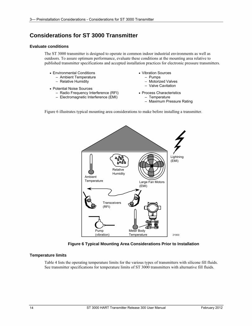
3— Preinstallation Considerations - Considerations for ST 3000 Transmitter
Considerations for ST 3000 Transmitter
Evaluate conditions
The ST 3000 transmitter is designed to operate in common indoor industrial environments as well as outdoors. To assure optimum performance, evaluate these conditions at the mounting area relative to published transmitter specifications and accepted installation practices for electronic pressure transmitters.
Environmental Conditions
– Ambient Temperature – Relative Humidity
Potential Noise Sources – Radio Frequency Interference (RFI) – Electromagnetic Interference (EMI)
Vibration Sources – Pumps – Motorized Valves – Valve Cavitation
Process Characteristics – Temperature – Maximum Pressure Rating
Figure 6 illustrates typical mounting area considerations to make before installing a transmitter.
Ambient Temperature
Relative Humidity
Large Fan Motors (EMI)
Transceivers (RFI)
Pump (vibration)
Meter Body Temperature
Lightning (EMI)
21003
Figure 6 Typical Mounting Area Considerations Prior to Installation
Temperature limits
Table 4 lists the operating temperature limits for the various types of transmitters with silicone fill fluids. See transmitter specifications for temperature limits of ST 3000 transmitters with alternative fill fluids.
ST 3000 HART Transmitter Release 300 User Manual February 2012 14
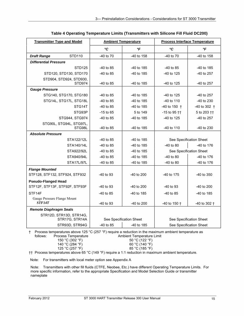
3— Preinstallation Considerations - Considerations for ST 3000 Transmitter
Table 4 Operating Temperature Limits (Transmitters with Silicone Fill Fluid DC200)
Transmitter Type and Model Ambient Temperature Process Interface Temperature
°C °F °C °F
Draft Range STD110 -40 to 70 -40 to 158 -40 to 70 -40 to 158
Differential Pressure
STD125
STD120, STD130, STD170
STD904, STD924, STD930, STD974
-40 to 85
-40 to 85
-40 to 85
-40 to 185
-40 to 185
-40 to 185
-40 to 85
-40 to 125
-40 to 125
-40 to 185
-40 to 257
-40 to 257
Gauge Pressure
STG140, STG170, STG180
STG14L, STG17L, STG18L
STG14T
STG93P
STG944, STG974
STG90L, STG94L, STG97L, STG98L
-40 to 85
-40 to 85
-40 to 85
-15 to 65
-40 to 85
-40 to 85
-40 to 185
-40 to 185
-40 to 185
5 to 149
-40 to 185
-40 to 185
-40 to 125
-40 to 110
-40 to 150 †
-15 to 95 ††
-40 to 125
-40 to 110
-40 to 257
-40 to 230
-40 to 302 †
5 to 203 ††
-40 to 257
-40 to 230
Absolute Pressure
STA122/12L
-40 to 85
-40 to 185
See Specification Sheet
STA140/14L -40 to 85 -40 to 185 -40 to 80 -40 to 176
STA922/92L -40 to 85 -40 to 185 See Specification Sheet
STA940/94L -40 to 85 -40 to 185 -40 to 80 -40 to 176
STA17L/97L -40 to 85 -40 to 185 -40 to 80 -40 to 176
Flange Mounted
STF128, STF132, STF924, STF932
Pseudo-Flanged Head
STF12F, STF13F, STF92F, STF93F
STF14F
Gauge Pressure Flange Mount STF14T
-40 to 93
-40 to 93
-40 to 85
-40 to 93
-40 to 200
-40 to 200
-40 to 185
-40 to 200
-40 to 175
-40 to 93
-40 to 85
-40 to 150 †
-40 to 350
-40 to 200
-40 to 185
-40 to 302 †
Remote Diaphragm Seals
STR12D, STR13D, STR14G, STR17G, STR14A
See Specification Sheet
See Specification Sheet
STR93D, STR94G -40 to 85 -40 to 185 See Specification Sheet
† Process temperatures above 125 °C (257 °F) require a reduction in the maximum ambient temperature as follows: Process Temperature Ambient Temperature Limit 150 °C (302 °F) 50 °C (122 °F) 140 °C (284 °F) 60 °C (140 °F) 125 °C (257 °F) 85 °C (185 °F) †† Process temperatures above 65 °C (149 °F) require a 1:1 reduction in maximum ambient temperature.
Note: For transmitters with local meter option see Appendix A
Note: Transmitters with other fill fluids (CTFE, Neobee, Etc.) have different Operating Temperature Limits. For more specific information, refer to the appropriate Specification and Model Selection Guide or transmitter nameplate
February 2012 ST 3000 HART Transmitter Release 300 User Manual 15
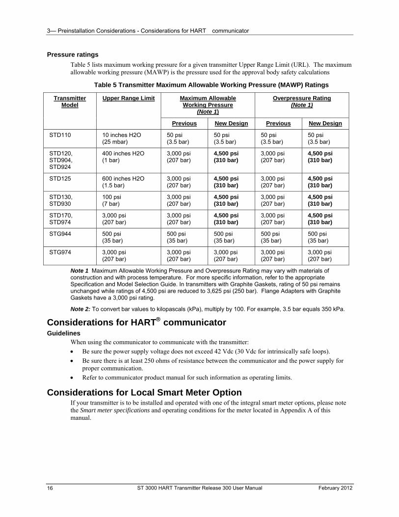
3— Preinstallation Considerations - Considerations for HART communicator
ST 3000 HART Transmitter Release 300 User Manual February 2012 16
Pressure ratings
Table 5 lists maximum working pressure for a given transmitter Upper Range Limit (URL). The maximum allowable working pressure (MAWP) is the pressure used for the approval body safety calculations
Table 5 Transmitter Maximum Allowable Working Pressure (MAWP) Ratings
Maximum Allowable Working Pressure
(Note 1)
Overpressure Rating (Note 1)
Transmitter Model
Upper Range Limit
Previous New Design Previous New Design
STD110 10 inches H2O (25 mbar)
50 psi (3.5 bar)
50 psi (3.5 bar)
50 psi (3.5 bar)
50 psi (3.5 bar)
STD120, STD904, STD924
400 inches H2O (1 bar)
3,000 psi (207 bar)
4,500 psi (310 bar)
3,000 psi (207 bar)
4,500 psi (310 bar)
STD125 600 inches H2O (1.5 bar)
3,000 psi (207 bar)
4,500 psi (310 bar)
3,000 psi (207 bar)
4,500 psi (310 bar)
STD130, STD930
100 psi (7 bar)
3,000 psi (207 bar)
4,500 psi (310 bar)
3,000 psi (207 bar)
4,500 psi (310 bar)
STD170, STD974
3,000 psi (207 bar)
3,000 psi (207 bar)
4,500 psi (310 bar)
3,000 psi (207 bar)
4,500 psi (310 bar)
STG944 500 psi (35 bar)
500 psi (35 bar)
500 psi (35 bar)
500 psi (35 bar)
500 psi (35 bar)
STG974 3,000 psi (207 bar)
3,000 psi (207 bar)
3,000 psi (207 bar)
3,000 psi (207 bar)
3,000 psi (207 bar)
Note 1 Maximum Allowable Working Pressure and Overpressure Rating may vary with materials of construction and with process temperature. For more specific information, refer to the appropriate Specification and Model Selection Guide. In transmitters with Graphite Gaskets, rating of 50 psi remains unchanged while ratings of 4,500 psi are reduced to 3,625 psi (250 bar). Flange Adapters with Graphite Gaskets have a 3,000 psi rating.
Note 2: To convert bar values to kilopascals (kPa), multiply by 100. For example, 3.5 bar equals 350 kPa.
Considerations for HART communicator Guidelines
When using the communicator to communicate with the transmitter:
Be sure the power supply voltage does not exceed 42 Vdc (30 Vdc for intrinsically safe loops).
Be sure there is at least 250 ohms of resistance between the communicator and the power supply for proper communication.
Refer to communicator product manual for such information as operating limits.
Considerations for Local Smart Meter Option If your transmitter is to be installed and operated with one of the integral smart meter options, please note the Smart meter specifications and operating conditions for the meter located in Appendix A of this manual.
4— Installation - Overview
4— Installation
Overview
About this section
This section provides information about installing the ST 3000 transmitter. The topics in this section include:
Mounting the ST 3000 transmitter - various mounting methods are described and can be used depending upon the transmitter type.
Piping the transmitter to the process – connecting the transmitter meter body to the process piping or tank connection.
Wiring the transmitter – connecting the loop wiring and ground conductors to the transmitter, and information is given on connecting local and remote indicating meters to the transmitter.
Mounting ST 3000 Transmitter
Summary
You can mount all transmitter models (except flush mount models and those with integral flanges) to a 2-inch (50 millimeter) vertical or horizontal pipe using our optional angle or flat mounting bracket, or a bracket of your own. Flush mount models are mounted directly to the process pipe or tank by a 1” weld nipple. Those models with integral flanges are supported by the flange connection.
Figure 7 shows typical bracket mounted and flange mounted transmitter installations for comparison.
Dimensions
Detailed dimension drawings for given transmitter series and types are listed in Section 13 in this manual for reference. Note that abbreviated overall dimensions are also shown in the specification sheets for the given transmitter models.
The procedures following assume that the mounting dimensions have already been taken into account and the mounting area can accommodate the transmitter.
February 2012 ST 3000 HART Transmitter Release 300 User Manual 17
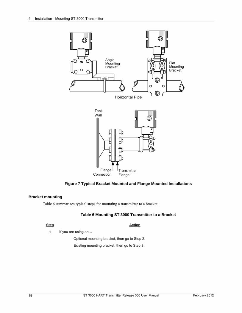
4— Installation - Mounting ST 3000 Transmitter
AngleMountingBracket
FlatMountingBracket
Horizontal Pipe
TankWall
TransmitterFlange
FlangeConnection
Figure 7 Typical Bracket Mounted and Flange Mounted Installations
Bracket mounting
Table 6 summarizes typical steps for mounting a transmitter to a bracket.
Table 6 Mounting ST 3000 Transmitter to a Bracket
Step Action
1 If you are using an…
Optional mounting bracket, then go to Step 2.
Existing mounting bracket, then go to Step 3.
ST 3000 HART Transmitter Release 300 User Manual February 2012 18
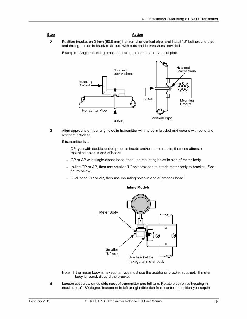
4— Installation - Mounting ST 3000 Transmitter
February 2012 ST 3000 HART Transmitter Release 300 User Manual 19
Step Action
2 Position bracket on 2-inch (50.8 mm) horizontal or vertical pipe, and install “U” bolt around pipe and through holes in bracket. Secure with nuts and lockwashers provided.
Example - Angle mounting bracket secured to horizontal or vertical pipe.
Horizontal Pipe
MountingBracket
Nuts andLockwashersNuts and
Lockwashers
U-Bolt
U-Bolt
MountingBracket
Vertical Pipe
3 Align appropriate mounting holes in transmitter with holes in bracket and secure with bolts and
washers provided.
If transmitter is …
DP type with double-ended process heads and/or remote seals, then use alternate mounting holes in end of heads
GP or AP with single-ended head, then use mounting holes in side of meter body.
In-line GP or AP, then use smaller “U” bolt provided to attach meter body to bracket. See figure below.
Dual-head GP or AP, then use mounting holes in end of process head.
Inline Models
Meter Body
Smaller“U” bolt
Use bracket forhexagonal meter body
Note: If the meter body is hexagonal, you must use the additional bracket supplied. If meter body is round, discard the bracket.
4 Loosen set screw on outside neck of transmitter one full turn. Rotate electronics housing in maximum of 180 degree increment in left or right direction from center to position you require
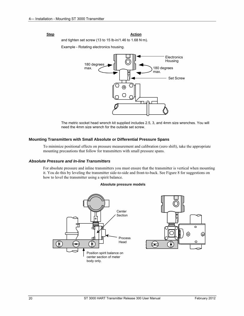
4— Installation - Mounting ST 3000 Transmitter
ST 3000 HART Transmitter Release 300 User Manual February 2012 20
Step Action
and tighten set screw (13 to 15 lb-in/1.46 to 1.68 N.m).
Example - Rotating electronics housing.
Set Screw
ElectronicsHousing
180 degreesmax.
180 degreesmax.
The metric socket head wrench kit supplied includes 2.5, 3, and 4mm size wrenches. You will need the 4mm size wrench for the outside set screw.
Mounting Transmitters with Small Absolute or Differential Pressure Spans
To minimize positional effects on pressure measurement and calibration (zero shift), take the appropriate mounting precautions that follow for transmitters with small pressure spans.
Absolute Pressure and In-line Transmitters
For absolute pressure and inline transmitters you must ensure that the transmitter is vertical when mounting it. You do this by leveling the transmitter side-to-side and front-to-back. See Figure 8 for suggestions on how to level the transmitter using a spirit balance.
Absolute pressure models
CenterSection
ProcessHead
Position spirit balance oncenter section of meterbody only.
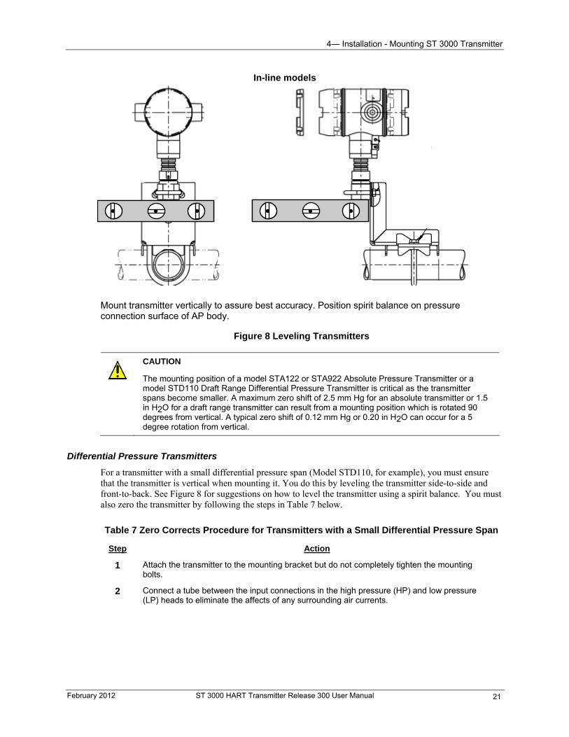
4— Installation - Mounting ST 3000 Transmitter
In-line models
Mount transmitter vertically to assure best accuracy. Position spirit balance on pressure connection surface of AP body.
Figure 8 Leveling Transmitters
CAUTION
The mounting position of a model STA122 or STA922 Absolute Pressure Transmitter or a model STD110 Draft Range Differential Pressure Transmitter is critical as the transmitter spans become smaller. A maximum zero shift of 2.5 mm Hg for an absolute transmitter or 1.5 in H2O for a draft range transmitter can result from a mounting position which is rotated 90 degrees from vertical. A typical zero shift of 0.12 mm Hg or 0.20 in H2O can occur for a 5 degree rotation from vertical.
Differential Pressure Transmitters
For a transmitter with a small differential pressure span (Model STD110, for example), you must ensure that the transmitter is vertical when mounting it. You do this by leveling the transmitter side-to-side and front-to-back. See Figure 8 for suggestions on how to level the transmitter using a spirit balance. You must also zero the transmitter by following the steps in Table 7 below.
Table 7 Zero Corrects Procedure for Transmitters with a Small Differential Pressure Span
Step Action
1 Attach the transmitter to the mounting bracket but do not completely tighten the mounting bolts.
2 Connect a tube between the input connections in the high pressure (HP) and low pressure (LP) heads to eliminate the affects of any surrounding air currents.
February 2012 ST 3000 HART Transmitter Release 300 User Manual 21
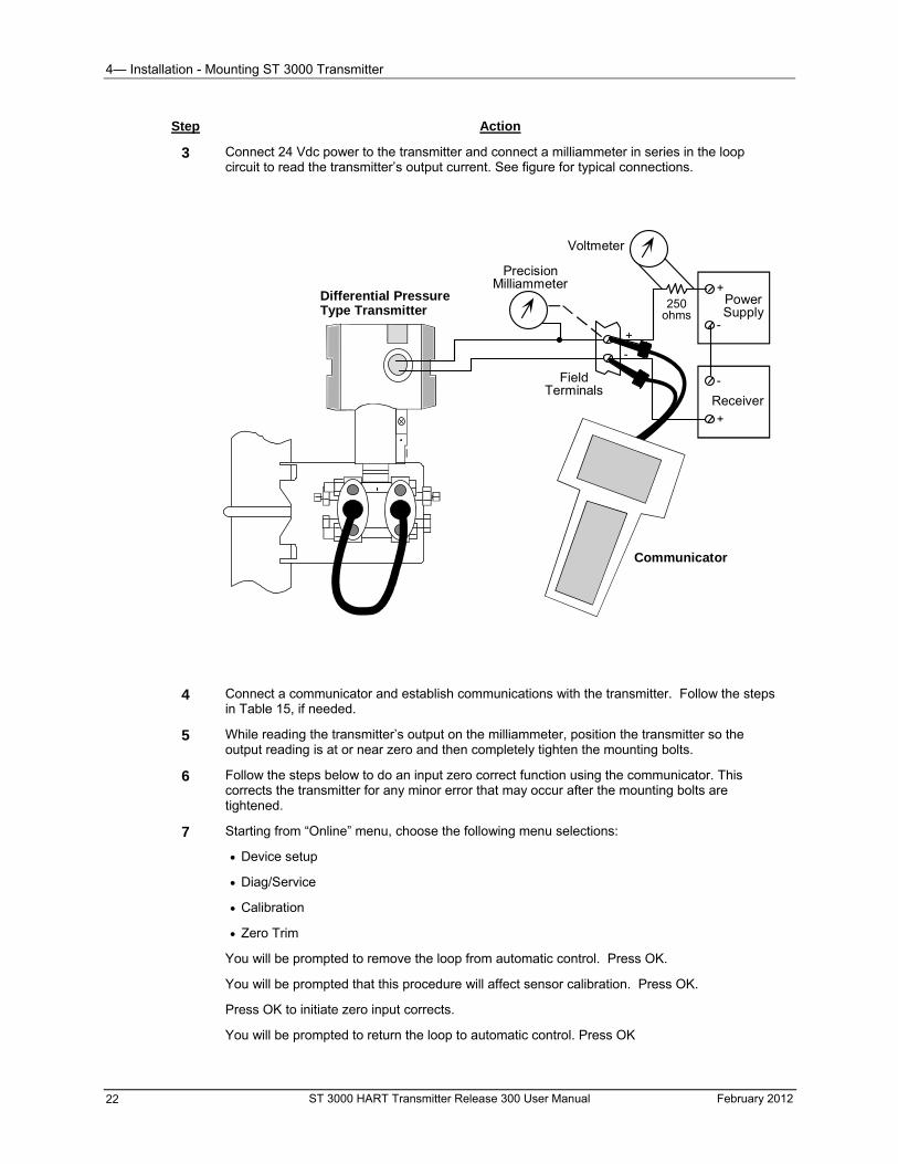
4— Installation - Mounting ST 3000 Transmitter
ST 3000 HART Transmitter Release 300 User Manual February 2012 22
Step Action
3 Connect 24 Vdc power to the transmitter and connect a milliammeter in series in the loop circuit to read the transmitter’s output current. See figure for typical connections.
-
+
-
+
250ohms
PowerSupply
Receiver
+
-
Voltmeter
FieldTerminals
PrecisionMilliammeter
Communicator
Differential PressureType Transmitter
4 Connect a communicator and establish communications with the transmitter. Follow the steps in Table 15, if needed.
5 While reading the transmitter’s output on the milliammeter, position the transmitter so the output reading is at or near zero and then completely tighten the mounting bolts.
6 Follow the steps below to do an input zero correct function using the communicator. This corrects the transmitter for any minor error that may occur after the mounting bolts are tightened.
7 Starting from “Online” menu, choose the following menu selections:
Device setup
Diag/Service
Calibration
Zero Trim
You will be prompted to remove the loop from automatic control. Press OK.
You will be prompted that this procedure will affect sensor calibration. Press OK.
Press OK to initiate zero input corrects.
You will be prompted to return the loop to automatic control. Press OK
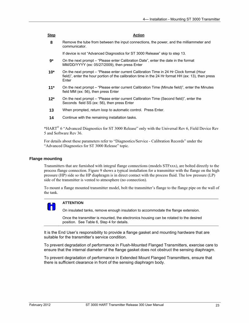
4— Installation - Mounting ST 3000 Transmitter
February 2012 ST 3000 HART Transmitter Release 300 User Manual 23
Step Action
8 Remove the tube from between the input connections, the power, and the milliammeter and communicator.
If device is not “Advanced Diagnostics for ST 3000 Release” skip to step 13.
9* On the next prompt – “Please enter Calibration Date”, enter the date in the format MM/DD/YYYY (ex: 05/27/2009), then press Enter
10* On the next prompt – “Please enter current Calibration Time in 24 Hr Clock format (Hour field)”, enter the hour portion of the calibration time in the 24 Hr format HH (ex: 13), then press Enter
11* On the next prompt – “Please enter current Calibration Time (Minute field)”, enter the Minutes field MM (ex: 56), then press Enter
12* On the next prompt – “Please enter current Calibration Time (Second field)”, enter the Seconds field SS (ex: 56), then press Enter
13 When prompted, return loop to automatic control. Press Enter.
14 Continue with the remaining installation tasks.
*HART 6 “Advanced Diagnostics for ST 3000 Release” only with the Universal Rev 6, Field Device Rev 5 and Software Rev 36.
For details about these parameters refer to “Diagnostics/Service - Calibration Records” under the “Advanced Diagnostics for ST 3000 Release” topic.
Flange mounting
Transmitters that are furnished with integral flange connections (models STFxxx), are bolted directly to the process flange connection. Figure 9 shows a typical installation for a transmitter with the flange on the high pressure (HP) side so the HP diaphragm is in direct contact with the process fluid. The low pressure (LP) side of the transmitter is vented to atmosphere (no connection).
To mount a flange mounted transmitter model, bolt the transmitter’s flange to the flange pipe on the wall of the tank.
ATTENTION
On insulated tanks, remove enough insulation to accommodate the flange extension.
Once the transmitter is mounted, the electronics housing can be rotated to the desired position. See Table 6, Step 4 for details.
It is the End User’s responsibility to provide a flange gasket and mounting hardware that are suitable for the transmitter’s service condition.
To prevent degradation of performance in Flush-Mounted Flanged Transmitters, exercise care to ensure that the internal diameter of the flange gasket does not obstruct the sensing diaphragm.
To prevent degradation of performance in Extended Mount Flanged Transmitters, ensure that there is sufficient clearance in front of the sensing diaphragm body.
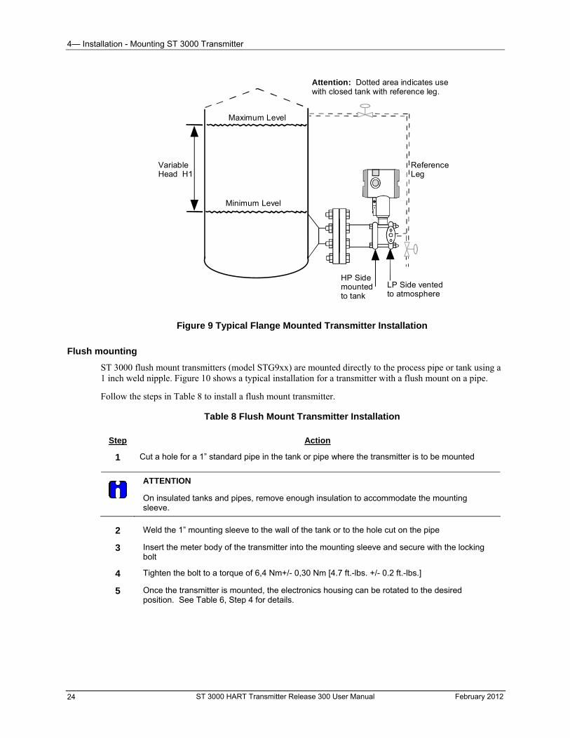
4— Installation - Mounting ST 3000 Transmitter
VariableHead H1
ReferenceLeg
Attention: Dotted area indicates usewith closed tank with reference leg.
LP Side ventedto atmosphere
HP Sidemountedto tank
Minimum Level
Maximum Level
Figure 9 Typical Flange Mounted Transmitter Installation
Flush mounting
ST 3000 flush mount transmitters (model STG9xx) are mounted directly to the process pipe or tank using a 1 inch weld nipple. Figure 10 shows a typical installation for a transmitter with a flush mount on a pipe.
Follow the steps in Table 8 to install a flush mount transmitter.
Table 8 Flush Mount Transmitter Installation
Step Action
1 Cut a hole for a 1” standard pipe in the tank or pipe where the transmitter is to be mounted
ATTENTION
On insulated tanks and pipes, remove enough insulation to accommodate the mounting sleeve.
2 Weld the 1” mounting sleeve to the wall of the tank or to the hole cut on the pipe
3 Insert the meter body of the transmitter into the mounting sleeve and secure with the locking bolt
4 Tighten the bolt to a torque of 6,4 Nm+/- 0,30 Nm [4.7 ft.-lbs. +/- 0.2 ft.-lbs.]
5 Once the transmitter is mounted, the electronics housing can be rotated to the desired position. See Table 6, Step 4 for details.
ST 3000 HART Transmitter Release 300 User Manual February 2012 24
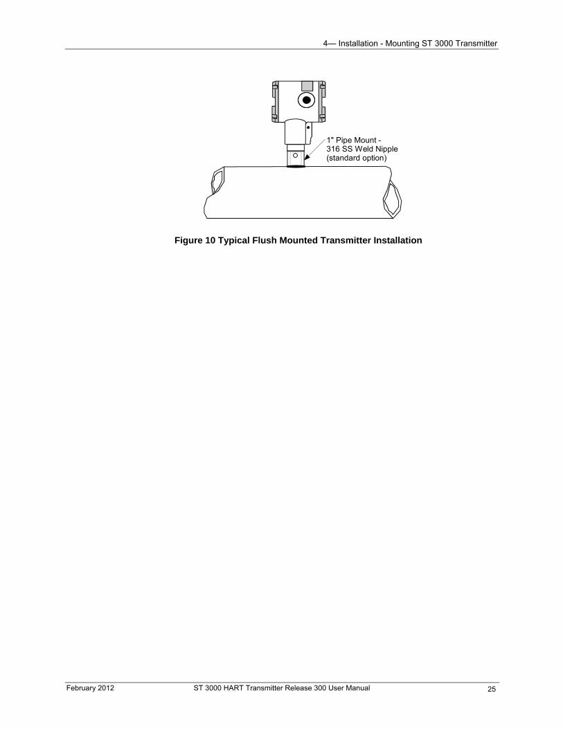
4— Installation - Mounting ST 3000 Transmitter
1" Pipe Mount -316 SS Weld Nipple(standard option)
Figure 10 Typical Flush Mounted Transmitter Installation
February 2012 ST 3000 HART Transmitter Release 300 User Manual 25
4— Installation - Mounting ST 3000 Transmitter
High Temperature Transmitter Mounting
You can mount the high temperature transmitter directly to the process flange connection or the process piping.
Figure 11 shows typical pipe and flange mounted transmitter installations for comparison.
To mount a flange mounted transmitter model, bolt the transmitter’s flange to the flange on the wall of the tank or process pipe.
It is the End User’s responsibility to provide a flange gasket and mounting hardware that are suitable for the transmitter’s service condition.
ATTENTION
On insulated tanks, remove enough insulation to accommodate the flange extension.
Once the transmitter is mounted, the electronics housing can be rotated to the desired position. See Table 6, step 4.
ST 3000 HART Transmitter Release 300 User Manual February 2012 26
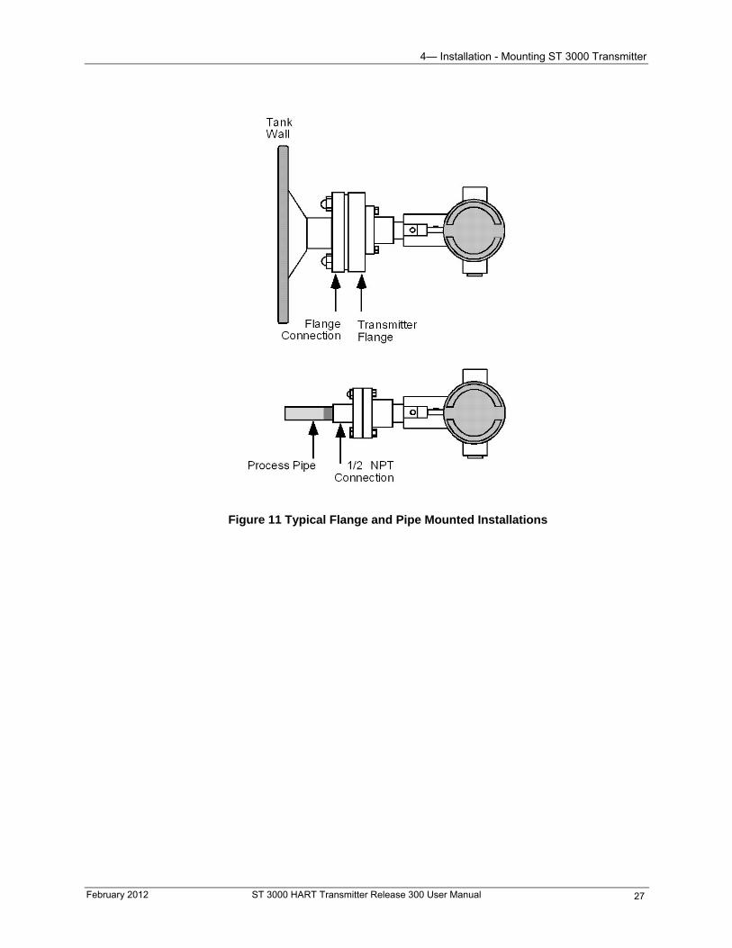
4— Installation - Mounting ST 3000 Transmitter
Figure 11 Typical Flange and Pipe Mounted Installations
February 2012 ST 3000 HART Transmitter Release 300 User Manual 27
4— Installation - Mounting ST 3000 Transmitter
ST 3000 HART Transmitter Release 300 User Manual February 2012 28
Remote seal mounting
ST 3000 transmitters furnished with remote diaphragm seals (models STRxxx) can be mounted using the optional mounting brackets. (See procedure in Table 6 in this section for bracket mounting.) Follow the guidelines below to determine the mounting position of the remote seals for the given fill fluid and then use the procedure in Table 9 to mount the remote seals to the process connections.
Figure 12 shows a typical installation for a remote diaphragm seal transmitter for reference.
WARNING
Mount the remote seal flanges within the limits stated below for the given fill-fluid in the capillary tubes.
IF the fill fluid is… THEN mount the flange…
Silicone DC 200 Oil no greater than 22 feet (6.7 meters) below the transmitter.
Silicone DC 704 Oil no greater than 19 feet (5.8 meters) below the transmitter.
Chlorotrifluorethylene (CTFE) no greater than 11 feet (3.4 meters) below the transmitter.
NOTE: The combination of tank vacuum and high pressure capillary head effect should not exceed 9 psi (300 mm Hg) absolute.
Table 9 Mounting Remote Diaphragm Seal Transmitter
Step Action
1 Mount transmitter at a remote distance determined by length of capillary tubing.
2 To measure variable head H1, mount remote seals on tank walls as follows:
If Transmitter Model Number is… STR93D or STR12D, then connect remote seal on high pressure (HP) side of transmitter to either the lower flange or the upper flange.
If Transmitter Model Number is… STR13D, the remote seal on low pressure (LP) side of transmitter must be connected to lower flange.
See Figure 12.
ATTENTION
On insulated tanks, remove enough insulation to accommodate the flange extension.
3 It is the End User’s responsibility to provide a flange gasket and mounting hardware that are suitable for the transmitter’s service condition
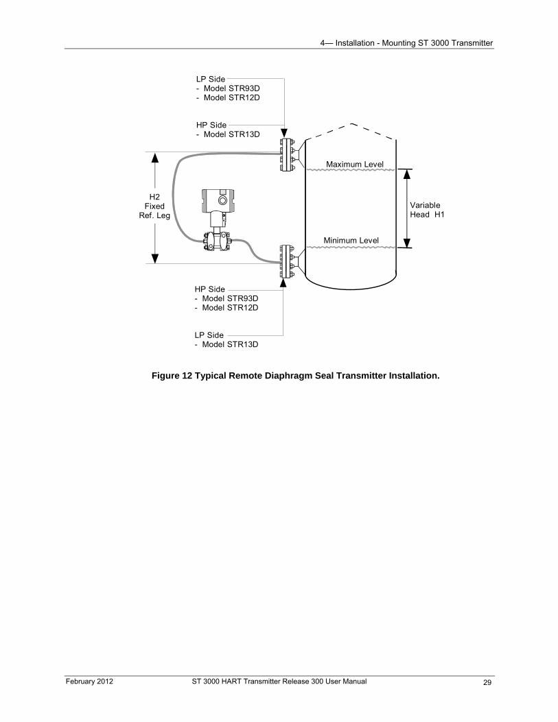
4— Installation - Mounting ST 3000 Transmitter
VariableHead H1
HP Side- Model STR93D- Model STR12D
LP Side- Model STR13D
Minimum Level
Maximum Level
LP Side- Model STR93D- Model STR12D
HP Side- Model STR13D
H2Fixed
Ref. Leg
Figure 12 Typical Remote Diaphragm Seal Transmitter Installation.
February 2012 ST 3000 HART Transmitter Release 300 User Manual 29
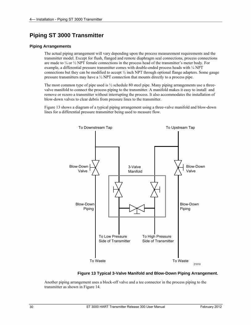
4— Installation - Piping ST 3000 Transmitter
Piping ST 3000 Transmitter
Piping Arrangements
The actual piping arrangement will vary depending upon the process measurement requirements and the transmitter model. Except for flush, flanged and remote diaphragm seal connections, process connections are made to ¼ or ½ NPT female connections in the process head of the transmitter’s meter body. For example, a differential pressure transmitter comes with double-ended process heads with ¼ NPT connections but they can be modified to accept ½ inch NPT through optional flange adapters. Some gauge pressure transmitters may have a ½ NPT connection that mounts directly to a process pipe.
The most common type of pipe used is ½ schedule 80 steel pipe. Many piping arrangements use a three-valve manifold to connect the process piping to the transmitter. A manifold makes it easy to install and remove or rezero a transmitter without interrupting the process. It also accommodates the installation of blow-down valves to clear debris from pressure lines to the transmitter.
Figure 13 shows a diagram of a typical piping arrangement using a three-valve manifold and blow-down lines for a differential pressure transmitter being used to measure flow.
ST 3000 HART Transmitter Release 300 User Manual February 2012 30
Blow-Down Valve
3-Valve Manifold
To Upstream TapTo Downstream Tap
To Low Pressure Side of Transmitter
To High Pressure Side of Transmitter
Blow-Down Valve
Blow-Down Piping
To WasteTo Waste
Blow-Down Piping
21010
Figure 13 Typical 3-Valve Manifold and Blow-Down Piping Arrangement.
Another piping arrangement uses a block-off valve and a tee connector in the process piping to the transmitter as shown in Figure 14.
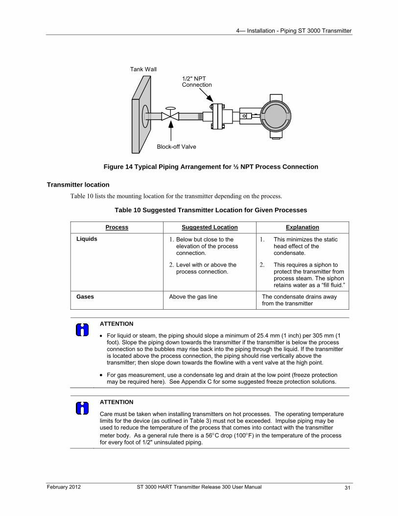
4— Installation - Piping ST 3000 Transmitter
Block-off Valve
1/2" NPTConnection
Tank Wall
Figure 14 Typical Piping Arrangement for ½ NPT Process Connection
Transmitter location
Table 10 lists the mounting location for the transmitter depending on the process.
Table 10 Suggested Transmitter Location for Given Processes
Process Suggested Location Explanation
Liquids 1. Below but close to the elevation of the process connection.
2. Level with or above the process connection.
1. This minimizes the static head effect of the condensate.
2. This requires a siphon to protect the transmitter from process steam. The siphon retains water as a “fill fluid.”
Gases Above the gas line The condensate drains away from the transmitter
ATTENTION
For liquid or steam, the piping should slope a minimum of 25.4 mm (1 inch) per 305 mm (1 foot). Slope the piping down towards the transmitter if the transmitter is below the process connection so the bubbles may rise back into the piping through the liquid. If the transmitter is located above the process connection, the piping should rise vertically above the transmitter; then slope down towards the flowline with a vent valve at the high point.
For gas measurement, use a condensate leg and drain at the low point (freeze protection may be required here). See Appendix C for some suggested freeze protection solutions.
ATTENTION
Care must be taken when installing transmitters on hot processes. The operating temperature limits for the device (as outlined in Table 3) must not be exceeded. Impulse piping may be used to reduce the temperature of the process that comes into contact with the transmitter meter body. As a general rule there is a 56C drop (100F) in the temperature of the process for every foot of 1/2" uninsulated piping.
February 2012 ST 3000 HART Transmitter Release 300 User Manual 31
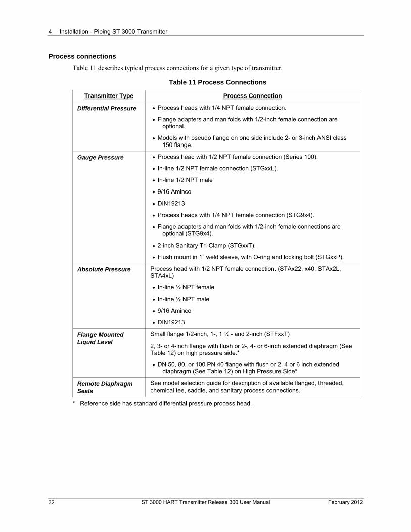
4— Installation - Piping ST 3000 Transmitter
ST 3000 HART Transmitter Release 300 User Manual February 2012 32
Process connections
Table 11 describes typical process connections for a given type of transmitter.
Table 11 Process Connections
Transmitter Type Process Connection
Differential Pressure
Process heads with 1/4 NPT female connection.
Flange adapters and manifolds with 1/2-inch female connection are optional.
Models with pseudo flange on one side include 2- or 3-inch ANSI class 150 flange.
Gauge Pressure Process head with 1/2 NPT female connection (Series 100).
In-line 1/2 NPT female connection (STGxxL).
In-line 1/2 NPT male
9/16 Aminco
DIN19213
Process heads with 1/4 NPT female connection (STG9x4).
Flange adapters and manifolds with 1/2-inch female connections are optional (STG9x4).
2-inch Sanitary Tri-Clamp (STGxxT).
Flush mount in 1” weld sleeve, with O-ring and locking bolt (STGxxP).
Absolute Pressure Process head with 1/2 NPT female connection. (STAx22, x40, STAx2L, STA4xL)
In-line ½ NPT female
In-line ½ NPT male
9/16 Aminco
DIN19213
Flange Mounted Liquid Level
Small flange 1/2-inch, 1-, 1 ½ - and 2-inch (STFxxT)
2, 3- or 4-inch flange with flush or 2-, 4- or 6-inch extended diaphragm (See Table 12) on high pressure side.*
DN 50, 80, or 100 PN 40 flange with flush or 2, 4 or 6 inch extended diaphragm (See Table 12) on High Pressure Side*.
Remote Diaphragm Seals
See model selection guide for description of available flanged, threaded, chemical tee, saddle, and sanitary process connections.
* Reference side has standard differential pressure process head.
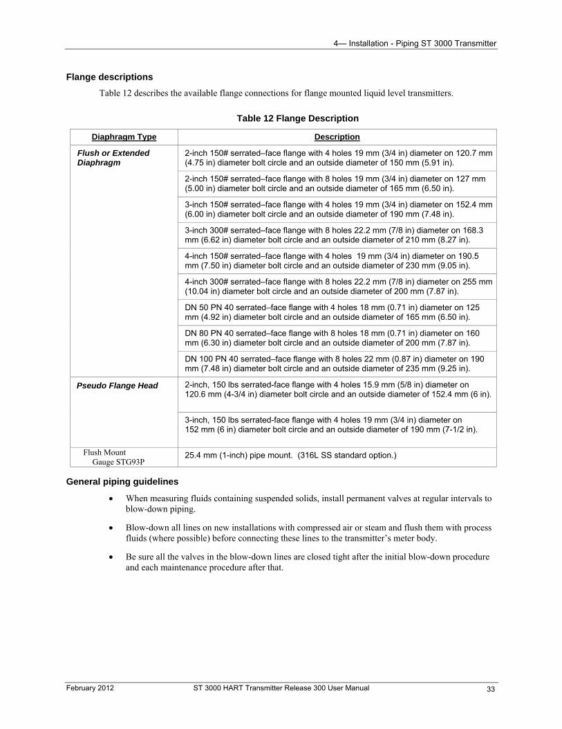
4— Installation - Piping ST 3000 Transmitter
Flange descriptions
Table 12 describes the available flange connections for flange mounted liquid level transmitters.
Table 12 Flange Description
Diaphragm Type Description
Flush or Extended Diaphragm
2-inch 150# serrated–face flange with 4 holes 19 mm (3/4 in) diameter on 120.7 mm (4.75 in) diameter bolt circle and an outside diameter of 150 mm (5.91 in).
2-inch 150# serrated–face flange with 8 holes 19 mm (3/4 in) diameter on 127 mm (5.00 in) diameter bolt circle and an outside diameter of 165 mm (6.50 in).
3-inch 150# serrated–face flange with 4 holes 19 mm (3/4 in) diameter on 152.4 mm (6.00 in) diameter bolt circle and an outside diameter of 190 mm (7.48 in).
3-inch 300# serrated–face flange with 8 holes 22.2 mm (7/8 in) diameter on 168.3 mm (6.62 in) diameter bolt circle and an outside diameter of 210 mm (8.27 in).
4-inch 150# serrated–face flange with 4 holes 19 mm (3/4 in) diameter on 190.5 mm (7.50 in) diameter bolt circle and an outside diameter of 230 mm (9.05 in).
4-inch 300# serrated–face flange with 8 holes 22.2 mm (7/8 in) diameter on 255 mm (10.04 in) diameter bolt circle and an outside diameter of 200 mm (7.87 in).
DN 50 PN 40 serrated–face flange with 4 holes 18 mm (0.71 in) diameter on 125 mm (4.92 in) diameter bolt circle and an outside diameter of 165 mm (6.50 in).
DN 80 PN 40 serrated–face flange with 8 holes 18 mm (0.71 in) diameter on 160 mm (6.30 in) diameter bolt circle and an outside diameter of 200 mm (7.87 in).
DN 100 PN 40 serrated–face flange with 8 holes 22 mm (0.87 in) diameter on 190 mm (7.48 in) diameter bolt circle and an outside diameter of 235 mm (9.25 in).
Pseudo Flange Head 2-inch, 150 lbs serrated-face flange with 4 holes 15.9 mm (5/8 in) diameter on 120.6 mm (4-3/4 in) diameter bolt circle and an outside diameter of 152.4 mm (6 in).
3-inch, 150 lbs serrated-face flange with 4 holes 19 mm (3/4 in) diameter on 152 mm (6 in) diameter bolt circle and an outside diameter of 190 mm (7-1/2 in).
Flush Mount Gauge STG93P
25.4 mm (1-inch) pipe mount. (316L SS standard option.)
General piping guidelines
When measuring fluids containing suspended solids, install permanent valves at regular intervals to blow-down piping.
Blow-down all lines on new installations with compressed air or steam and flush them with process fluids (where possible) before connecting these lines to the transmitter’s meter body.
Be sure all the valves in the blow-down lines are closed tight after the initial blow-down procedure and each maintenance procedure after that.
February 2012 ST 3000 HART Transmitter Release 300 User Manual 33
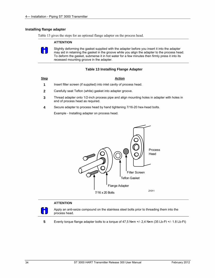
4— Installation - Piping ST 3000 Transmitter
Installing flange adapter
Table 13 gives the steps for an optional flange adapter on the process head.
ATTENTION
Slightly deforming the gasket supplied with the adapter before you insert it into the adapter may aid in retaining the gasket in the groove while you align the adapter to the process head. To deform the gasket, submerse it in hot water for a few minutes then firmly press it into its recessed mounting groove in the adapter.
Table 13 Installing Flange Adapter
Step Action
1 Insert filter screen (if supplied) into inlet cavity of process head.
2 Carefully seat Teflon (white) gasket into adapter groove.
3 Thread adapter onto 1/2-inch process pipe and align mounting holes in adapter with holes in end of process head as required.
4 Secure adapter to process head by hand tightening 7/16-20 hex-head bolts.
Example - Installing adapter on process head.
ProcessHead
Filter Screen
Teflon Gasket
Flange Adapter
7/16 x 20 Bolts21011
ATTENTION
Apply an anti-seize compound on the stainless steel bolts prior to threading them into the process head.
5 Evenly torque flange adapter bolts to a torque of 47,5 Nm +/- 2,4 Nm (35 Lb-Ft +/- 1.8 Lb-Ft)
ST 3000 HART Transmitter Release 300 User Manual February 2012 34
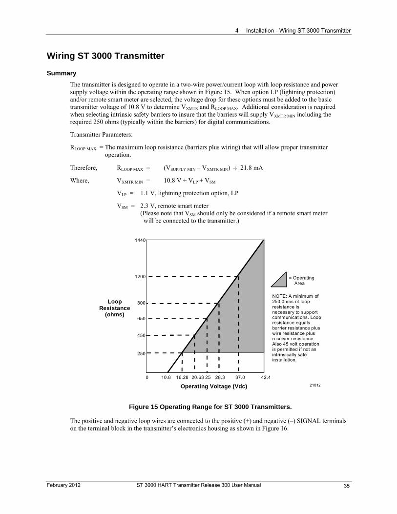
4— Installation - Wiring ST 3000 Transmitter
Wiring ST 3000 Transmitter
Summary
The transmitter is designed to operate in a two-wire power/current loop with loop resistance and power supply voltage within the operating range shown in Figure 15. When option LP (lightning protection) and/or remote smart meter are selected, the voltage drop for these options must be added to the basic transmitter voltage of 10.8 V to determine VXMTR and RLOOP MAX. Additional consideration is required when selecting intrinsic safety barriers to insure that the barriers will supply VXMTR MIN including the required 250 ohms (typically within the barriers) for digital communications.
Transmitter Parameters:
RLOOP MAX = The maximum loop resistance (barriers plus wiring) that will allow proper transmitter operation.
Therefore, RLOOP MAX = (VSUPPLY MIN – VXMTR MIN) 21.8 mA
Where, VXMTR MIN = 10.8 V + VLP + VSM
VLP = 1.1 V, lightning protection option, LP
VSM = 2.3 V, remote smart meter (Please note that VSM should only be considered if a remote smart meter will be connected to the transmitter.)
0 10.8 16.28 20.63 25 28.3 37.0 42.4
250
450
650
800
1200
1440
Operating Voltage (Vdc)
= Operating Area
NOTE: A minimum of250 0hms of loopresistance isnecessary to supportcommunications. Loopresistance equalsbarrier resistance pluswire resistance plusreceiver resistance.Also 45 volt operationis permitted if not anintrinsically safeinstallation.
LoopResistance
(ohms)
21012
Figure 15 Operating Range for ST 3000 Transmitters.
The positive and negative loop wires are connected to the positive (+) and negative (–) SIGNAL terminals on the terminal block in the transmitter’s electronics housing as shown in Figure 16.
February 2012 ST 3000 HART Transmitter Release 300 User Manual 35
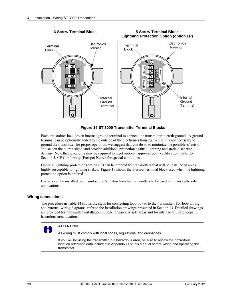
4— Installation - Wiring ST 3000 Transmitter
3-Screw Terminal Block 5-Screw Terminal Block Lightning Protection Option (option LP)
- S
IGN
AL
+
+
-
TE
ST
TerminalBlock
ElectronicsHousing
InternalGroundTerminal
+
+-
-
L-
SIG
NA
LM
ET
ER TE
ST
SIG
NA
L
-+
+-
TerminalBlock
ElectronicsHousing
InternalGroundTerminal
Figure 16 ST 3000 Transmitter Terminal Blocks
Each transmitter includes an internal ground terminal to connect the transmitter to earth ground. A ground terminal can be optionally added to the outside of the electronics housing. While it is not necessary to ground the transmitter for proper operation, we suggest that you do so to minimize the possible effects of “noise” on the output signal and provide additional protection against lightning and static discharge damage. Note that grounding may be required to meet optional approval body certification. Refer to Section 3, CE Conformity (Europe) Notice for special conditions.
Optional lightning protection (option LP) can be ordered for transmitters that will be installed in areas highly susceptible to lightning strikes. Figure 17 shows the 5-screw terminal block used when the lightning protection option is ordered.
Barriers can be installed per manufacturer’s instructions for transmitters to be used in intrinsically safe applications.
Wiring connections
The procedure in Table 14 shows the steps for connecting loop power to the transmitter. For loop wiring and external wiring diagrams, refer to the installation drawings presented in Section 13. Detailed drawings are provided for transmitter installation in non-intrinsically safe areas and for intrinsically safe loops in hazardous area locations.
ATTENTION
All wiring must comply with local codes, regulations, and ordinances.
If you will be using the transmitter in a hazardous area, be sure to review the hazardous location reference data included in Appendix D of this manual before wiring and operating the transmitter.
ST 3000 HART Transmitter Release 300 User Manual February 2012 36
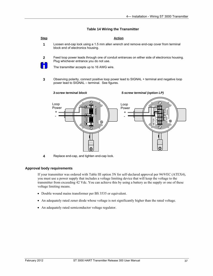
4— Installation - Wiring ST 3000 Transmitter
Table 14 Wiring the Transmitter
Step Action
1 Loosen end-cap lock using a 1.5 mm allen wrench and remove end-cap cover from terminal block end of electronics housing.
2
Feed loop power leads through one of conduit entrances on either side of electronics housing. Plug whichever entrance you do not use.
The transmitter accepts up to 16 AWG wire.
3 Observing polarity, connect positive loop power lead to SIGNAL + terminal and negative loop power lead to SIGNAL – terminal. See figures.
3-screw terminal block 5-screw terminal (option LP)
+
+-
-
L-
SIG
NA
LM
ET
ER TE
ST
SIG
NA
L
-+
+-+
-
LoopPower
- S
IGN
AL
+
+
-
TE
ST
+-
LoopPower
4 Replace end-cap, and tighten end-cap lock.
Approval body requirements
If your transmitter was ordered with Table III option 3N for self-declared approval per 94/9/EC (ATEX4), you must use a power supply that includes a voltage limiting device that will keep the voltage to the transmitter from exceeding 42 Vdc. You can achieve this by using a battery as the supply or one of these voltage limiting means.
Double wound mains transformer per BS 3535 or equivalent.
An adequately rated zener diode whose voltage is not significantly higher than the rated voltage.
An adequately rated semiconductor voltage regulator.
February 2012 ST 3000 HART Transmitter Release 300 User Manual 37
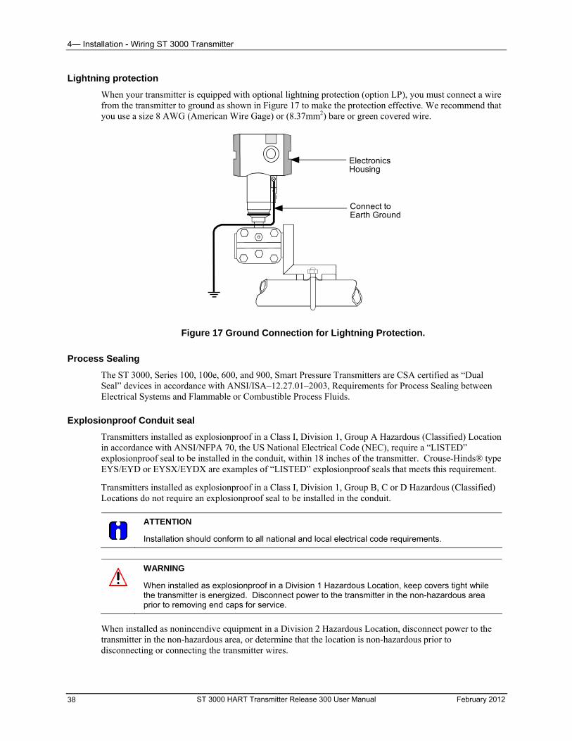
4— Installation - Wiring ST 3000 Transmitter
Lightning protection
When your transmitter is equipped with optional lightning protection (option LP), you must connect a wire from the transmitter to ground as shown in Figure 17 to make the protection effective. We recommend that you use a size 8 AWG (American Wire Gage) or (8.37mm2) bare or green covered wire.
ElectronicsHousing
Connect toEarth Ground
Figure 17 Ground Connection for Lightning Protection.
Process Sealing
The ST 3000, Series 100, 100e, 600, and 900, Smart Pressure Transmitters are CSA certified as “Dual Seal” devices in accordance with ANSI/ISA–12.27.01–2003, Requirements for Process Sealing between Electrical Systems and Flammable or Combustible Process Fluids.
Explosionproof Conduit seal
Transmitters installed as explosionproof in a Class I, Division 1, Group A Hazardous (Classified) Location in accordance with ANSI/NFPA 70, the US National Electrical Code (NEC), require a “LISTED” explosionproof seal to be installed in the conduit, within 18 inches of the transmitter. Crouse-Hinds® type EYS/EYD or EYSX/EYDX are examples of “LISTED” explosionproof seals that meets this requirement.
Transmitters installed as explosionproof in a Class I, Division 1, Group B, C or D Hazardous (Classified) Locations do not require an explosionproof seal to be installed in the conduit.
ATTENTION
Installation should conform to all national and local electrical code requirements.
WARNING
When installed as explosionproof in a Division 1 Hazardous Location, keep covers tight while the transmitter is energized. Disconnect power to the transmitter in the non-hazardous area prior to removing end caps for service.
When installed as nonincendive equipment in a Division 2 Hazardous Location, disconnect power to the transmitter in the non-hazardous area, or determine that the location is non-hazardous prior to disconnecting or connecting the transmitter wires.
ST 3000 HART Transmitter Release 300 User Manual February 2012 38
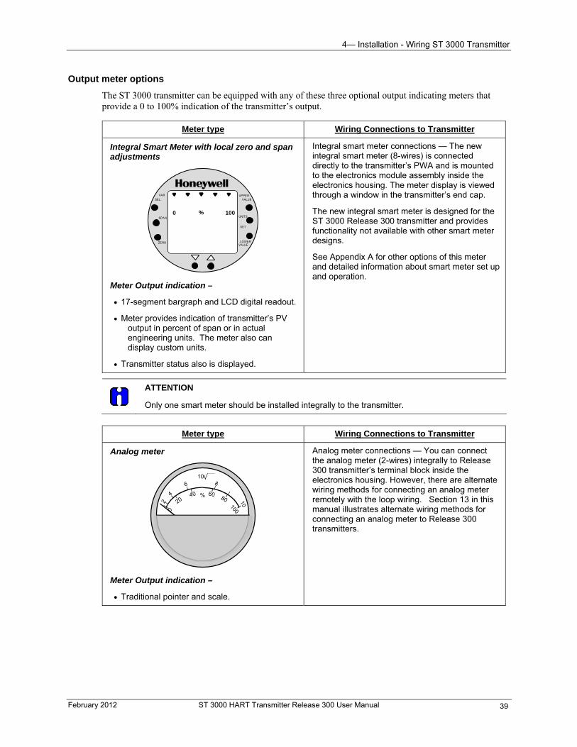
4— Installation - Wiring ST 3000 Transmitter
February 2012 ST 3000 HART Transmitter Release 300 User Manual 39
Output meter options
The ST 3000 transmitter can be equipped with any of these three optional output indicating meters that provide a 0 to 100% indication of the transmitter’s output.
Meter type Wiring Connections to Transmitter
Integral Smart Meter with local zero and span adjustments
UPPERVALUE
UNITS
LOWERVALUE
SET
VAR
SEL.
0
-SPAN
ZERO
% 1000
Meter Output indication –
17-segment bargraph and LCD digital readout.
Meter provides indication of transmitter’s PV output in percent of span or in actual engineering units. The meter also can display custom units.
Transmitter status also is displayed.
Integral smart meter connections — The new integral smart meter (8-wires) is connected directly to the transmitter’s PWA and is mounted to the electronics module assembly inside the electronics housing. The meter display is viewed through a window in the transmitter’s end cap.
The new integral smart meter is designed for the ST 3000 Release 300 transmitter and provides functionality not available with other smart meter designs.
See Appendix A for other options of this meter and detailed information about smart meter set up and operation.
ATTENTION
Only one smart meter should be installed integrally to the transmitter.
Meter type Wiring Connections to Transmitter
Analog meter
80
100
604020
0
%
10
2
4
6 8
10
Meter Output indication –
Traditional pointer and scale.
Analog meter connections — You can connect the analog meter (2-wires) integrally to Release 300 transmitter’s terminal block inside the electronics housing. However, there are alternate wiring methods for connecting an analog meter remotely with the loop wiring. Section 13 in this manual illustrates alternate wiring methods for connecting an analog meter to Release 300 transmitters.
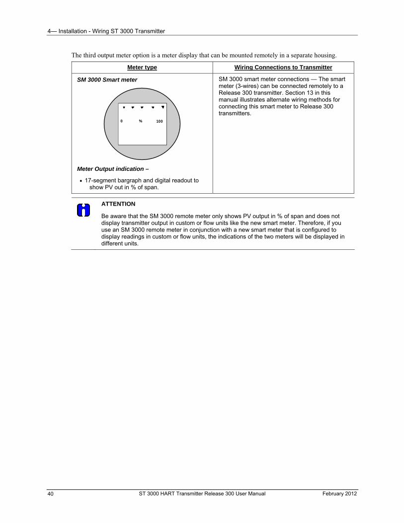
4— Installation - Wiring ST 3000 Transmitter
The third output meter option is a meter display that can be mounted remotely in a separate housing.
Meter type Wiring Connections to Transmitter
SM 3000 smart meter connections — The smart meter (3-wires) can be connected remotely to a Release 300 transmitter. Section 13 in this manual illustrates alternate wiring methods for connecting this smart meter to Release 300 transmitters.
SM 3000 Smart meter
0 100%
Meter Output indication –
17-segment bargraph and digital readout to show PV out in % of span.
ATTENTION
Be aware that the SM 3000 remote meter only shows PV output in % of span and does not display transmitter output in custom or flow units like the new smart meter. Therefore, if you use an SM 3000 remote meter in conjunction with a new smart meter that is configured to display readings in custom or flow units, the indications of the two meters will be displayed in different units.
ST 3000 HART Transmitter Release 300 User Manual February 2012 40
5— Getting Started - Overview
5— Getting Started
Overview
About this section
This section tells you how to establish communications with the ST 3000 and make initial checks of the transmitter’s settings and configuration using a HART hand-held communicator. This section includes these topics:
Verifying that the HART communicator contains the proper software version for communicating the ST 3000 transmitter.
Making proper connections of the HART communicator to the ST 3000 transmitter.
Begin communications between the transmitter and the communicator.
Make initial checks to the transmitter, such as checking factory set configuration, verify write protect option and failsafe direction, and change if necessary.
Establishing Communications
Software compatibility
You need to make sure your HART communicator contains software that is compatible with the ST 3000 HART transmitter.
To check software revision contained in the communicator:
1. Turn on the communicator and access the “Offline” menu.
2. Press “4” to select the Utility menu.
3. Press “5” to select Simulation mode.
4. The Manufacturer menu appears. Select “Honeywell”.
5. Select Model “ST3000”.
6. View the software revisions available for the selected model.
The software versions that are compatible with the ST 3000 HART Release 300 Smart Transmitter are:
ST 3000 HART 5 Version: Dev v2 (Device version 2) DD v1 (Device Description version 1)
ST 3000 HART 6 Version: Dev v4 (Device version 4) DD 2 (Device Description version 2)
ST3000 HART 6 Advanced Diagnostics Version: Dev v5 (Device version 5) DD v1 (Device Description version 1)
February 2012 ST 3000 HART Transmitter Release 300 User Manual 41

5— Getting Started - Establishing Communications
Upgrading HART communicator software
The memory module in the HART communicator is programmed with device descriptions for specific HART-compatible devices. These device descriptions allow the communicator to recognize and “talk to” the compatible devices. If you find that your communicator does not contain the necessary application software and device descriptions, contact your Honeywell sales representative about upgrading your communicator. See also the product manual that was supplied with your communicator for further information.
ST 3000 HART Transmitter Release 300 User Manual February 2012 42
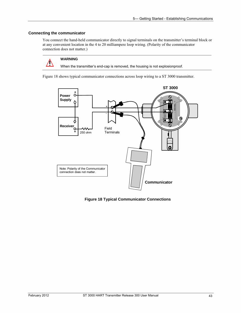
5— Getting Started - Establishing Communications
Connecting the communicator
You connect the hand-held communicator directly to signal terminals on the transmitter’s terminal block or at any convenient location in the 4 to 20 milliampere loop wiring. (Polarity of the communicator connection does not matter.)
WARNING
When the transmitter’s end-cap is removed, the housing is not explosionproof.
Figure 18 shows typical communicator connections across loop wiring to a ST 3000 transmitter.
- S
IGN
AL
+
+
-T
ES
T
PowerSupply
+
-
Receiver
+
-
FieldTerminals
Communicator
ST 3000
250 ohm
Note: Polarity of the Communicatorconnection does not matter.
Figure 18 Typical Communicator Connections
February 2012 ST 3000 HART Transmitter Release 300 User Manual 43
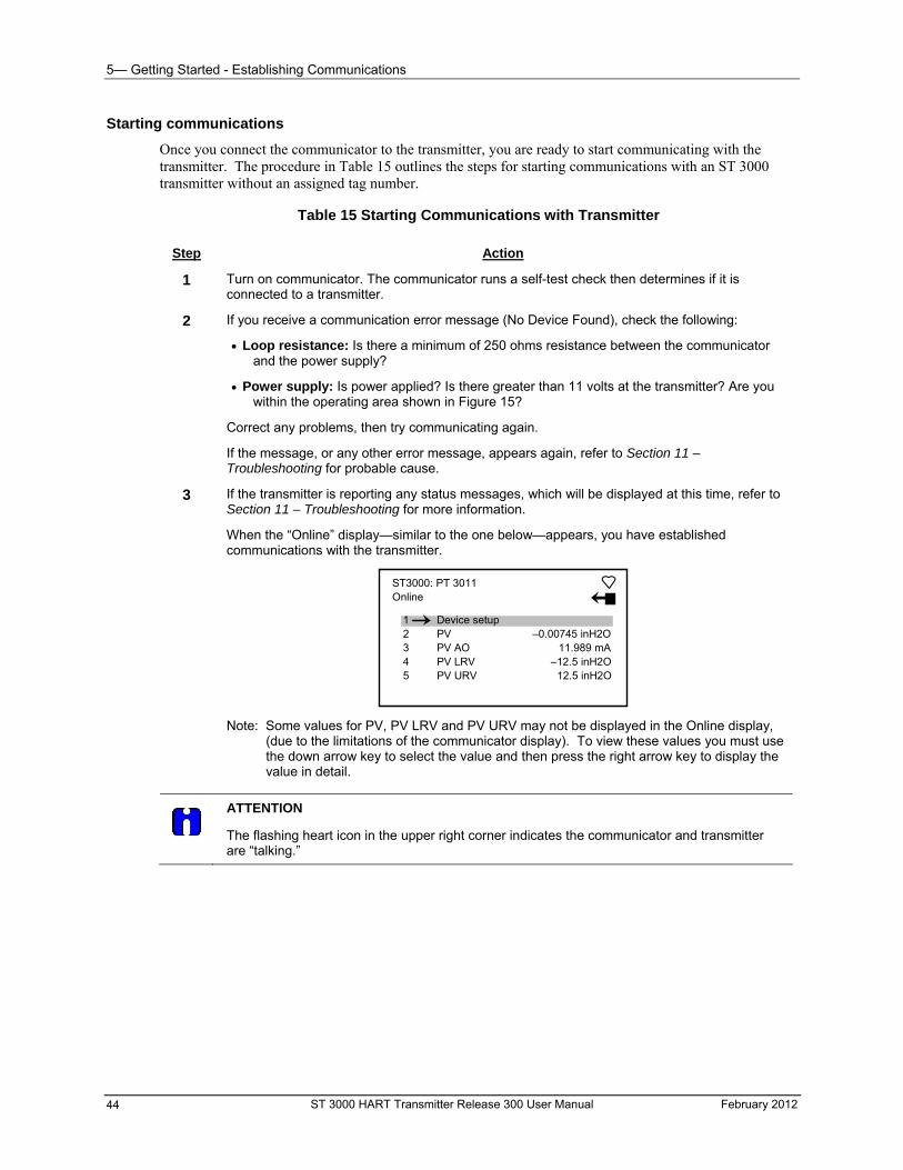
5— Getting Started - Establishing Communications
ST 3000 HART Transmitter Release 300 User Manual February 2012 44
Starting communications
Once you connect the communicator to the transmitter, you are ready to start communicating with the transmitter. The procedure in Table 15 outlines the steps for starting communications with an ST 3000 transmitter without an assigned tag number.
Table 15 Starting Communications with Transmitter
Step Action
1 Turn on communicator. The communicator runs a self-test check then determines if it is connected to a transmitter.
2 If you receive a communication error message (No Device Found), check the following:
Loop resistance: Is there a minimum of 250 ohms resistance between the communicator and the power supply?
Power supply: Is power applied? Is there greater than 11 volts at the transmitter? Are you within the operating area shown in Figure 15?
Correct any problems, then try communicating again.
If the message, or any other error message, appears again, refer to Section 11 – Troubleshooting for probable cause.
3 If the transmitter is reporting any status messages, which will be displayed at this time, refer to Section 11 – Troubleshooting for more information.
When the “Online” display—similar to the one below—appears, you have established communications with the transmitter.
ST3000: PT 3011 Online
3 4 5
PV AO PV LRV PV URV
–0.00745 inH2O 11.989 mA
–12.5 inH2O 12.5 inH2O
1 2
Device setup PV
Note: Some values for PV, PV LRV and PV URV may not be displayed in the Online display, (due to the limitations of the communicator display). To view these values you must use the down arrow key to select the value and then press the right arrow key to display the value in detail.
ATTENTION
The flashing heart icon in the upper right corner indicates the communicator and transmitter are “talking.”
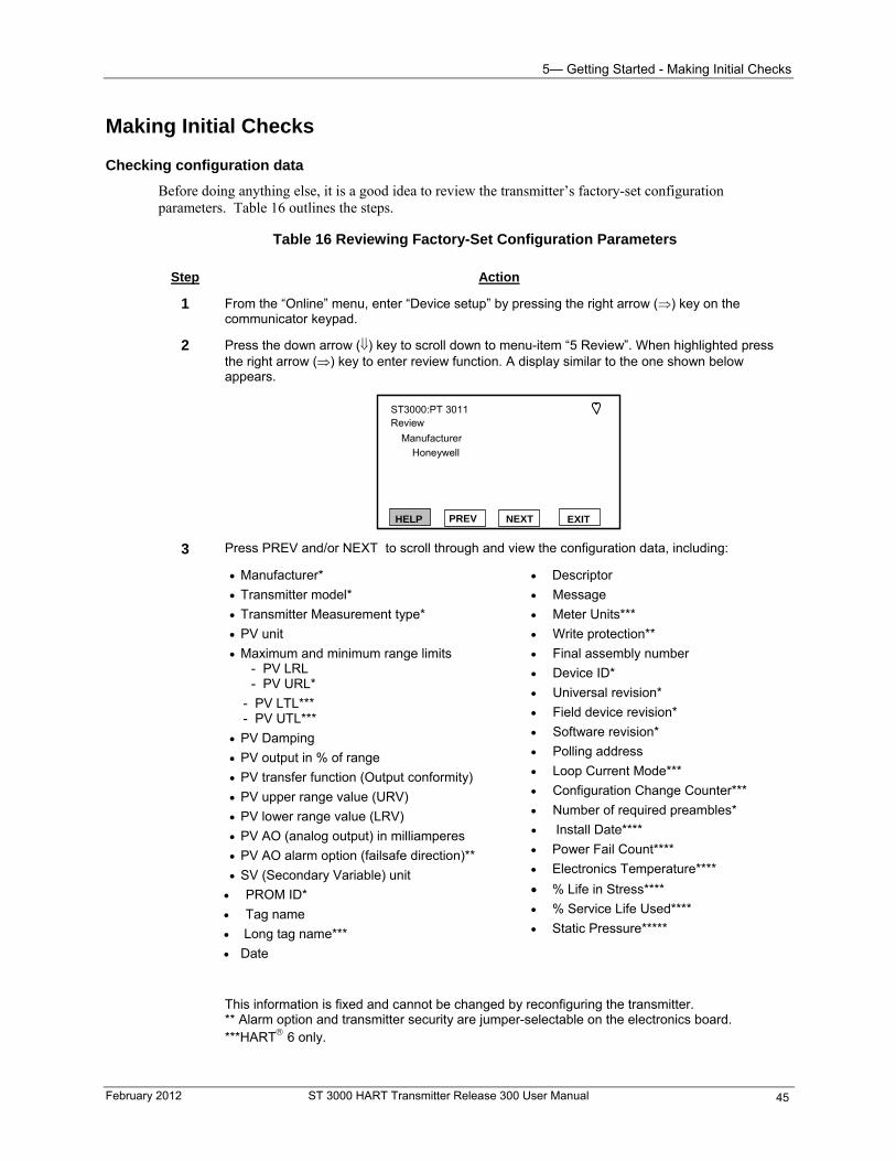
5— Getting Started - Making Initial Checks
February 2012 ST 3000 HART Transmitter Release 300 User Manual 45
Making Initial Checks
Checking configuration data
Before doing anything else, it is a good idea to review the transmitter’s factory-set configuration parameters. Table 16 outlines the steps.
Table 16 Reviewing Factory-Set Configuration Parameters
Step Action
1 From the “Online” menu, enter “Device setup” by pressing the right arrow () key on the communicator keypad.
2 Press the down arrow () key to scroll down to menu-item “5 Review”. When highlighted press the right arrow () key to enter review function. A display similar to the one shown below appears.
ST3000:PT 3011Review
Manufacturer
Honeywell
HELP EXITPREV NEXT
3 Press PREV and/or NEXT to scroll through and view the configuration data, including:
Manufacturer*
Transmitter model*
Transmitter Measurement type*
PV unit
Maximum and minimum range limits - PV LRL - PV URL*
- PV LTL*** - PV UTL***
PV Damping
PV output in % of range
PV transfer function (Output conformity)
PV upper range value (URV)
PV lower range value (LRV)
PV AO (analog output) in milliamperes
PV AO alarm option (failsafe direction)**
SV (Secondary Variable) unit
PROM ID*
Tag name
Long tag name***
Date
Descriptor
Message
Meter Units***
Write protection**
Final assembly number
Device ID*
Universal revision*
Field device revision*
Software revision*
Polling address
Loop Current Mode***
Configuration Change Counter***
Number of required preambles*
Install Date****
Power Fail Count****
Electronics Temperature****
% Life in Stress****
% Service Life Used****
Static Pressure*****
This information is fixed and cannot be changed by reconfiguring the transmitter. ** Alarm option and transmitter security are jumper-selectable on the electronics board. ***HART 6 only.
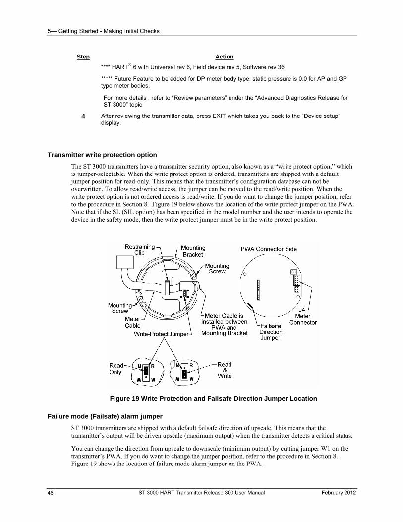
5— Getting Started - Making Initial Checks
Step Action
**** HART 6 with Universal rev 6, Field device rev 5, Software rev 36
***** Future Feature to be added for DP meter body type; static pressure is 0.0 for AP and GP type meter bodies.
For more details , refer to “Review parameters” under the “Advanced Diagnostics Release for ST 3000” topic
4 After reviewing the transmitter data, press EXIT which takes you back to the “Device setup” display.
Transmitter write protection option
The ST 3000 transmitters have a transmitter security option, also known as a “write protect option,” which is jumper-selectable. When the write protect option is ordered, transmitters are shipped with a default jumper position for read-only. This means that the transmitter’s configuration database can not be overwritten. To allow read/write access, the jumper can be moved to the read/write position. When the write protect option is not ordered access is read/write. If you do want to change the jumper position, refer to the procedure in Section 8. Figure 19 below shows the location of the write protect jumper on the PWA. Note that if the SL (SIL option) has been specified in the model number and the user intends to operate the device in the safety mode, then the write protect jumper must be in the write protect position.
Figure 19 Write Protection and Failsafe Direction Jumper Location
Failure mode (Failsafe) alarm jumper
ST 3000 transmitters are shipped with a default failsafe direction of upscale. This means that the transmitter’s output will be driven upscale (maximum output) when the transmitter detects a critical status.
You can change the direction from upscale to downscale (minimum output) by cutting jumper W1 on the transmitter’s PWA. If you do want to change the jumper position, refer to the procedure in Section 8. Figure 19 shows the location of failure mode alarm jumper on the PWA.
ST 3000 HART Transmitter Release 300 User Manual February 2012 46
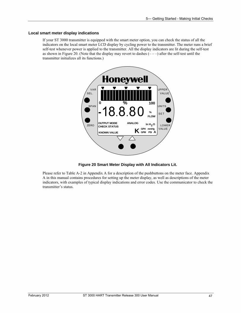
5— Getting Started - Making Initial Checks
Local smart meter display indications
If your ST 3000 transmitter is equipped with the smart meter option, you can check the status of all the indicators on the local smart meter LCD display by cycling power to the transmitter. The meter runs a brief self-test whenever power is applied to the transmitter. All the display indicators are lit during the self-test as shown in Figure 20. (Note that the display may revert to dashes (– – –) after the self-test until the transmitter initializes all its functions.)
% 1000
18 8.8ANALOG
%
FLOW
In H O2
K GPH mmHgGPM PSI A
OUTPUT MODECHECK STATUS
0-
UPPER
VALUE
UNITS
LOWERVALUE
S E T
VAR
SEL.
SPAN
ZERO
.
KNOWN VALUE
Figure 20 Smart Meter Display with All Indicators Lit.
Please refer to Table A-2 in Appendix A for a description of the pushbuttons on the meter face. Appendix A in this manual contains procedures for setting up the meter display, as well as descriptions of the meter indicators, with examples of typical display indications and error codes. Use the communicator to check the transmitter’s status.
February 2012 ST 3000 HART Transmitter Release 300 User Manual 47
6— Configuration - Overview
6— Configuration
Overview
About this section
This section introduces you to ST 3000 transmitter configuration. It identifies the parameters that make up the transmitter’s configuration database and provides procedures for entering values/selections for the given configuration parameters.
This section also provides an overview of the HART communicator, including data on menus and keyboard, descriptions of display selections and symbols, and information on making changes using the communicator.
Section contents
This section includes these topics.
An overview of the configuration process and how messages are exchanged between transmitter and communicator.
A summary of the ST 3000 configuration parameters and how to access this data using the communicator.
An overview of the communicator keyboard, displays and menu structure.
Procedures for configuring the ST 3000 transmitter with the communicator.
ST 3000 HART Transmitter Release 300 User Manual February 2012 48
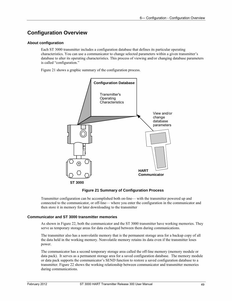
6— Configuration - Configuration Overview
Configuration Overview
About configuration
Each ST 3000 transmitter includes a configuration database that defines its particular operating characteristics. You can use a communicator to change selected parameters within a given transmitter’s database to alter its operating characteristics. This process of viewing and/or changing database parameters is called “configuration.”
Figure 21 shows a graphic summary of the configuration process.
ST 3000
Configuration Database
Transmitter'sOperatingCharacteristics
View and/orchangedatabaseparameters
HARTCommunicator
Figure 21 Summary of Configuration Process
Transmitter configuration can be accomplished both on-line— with the transmitter powered up and connected to the communicator, or off-line— where you enter the configuration in the communicator and then store it in memory for later downloading to the transmitter
Communicator and ST 3000 transmitter memories
As shown in Figure 22, both the communicator and the ST 3000 transmitter have working memories. They serve as temporary storage areas for data exchanged between them during communications.
The transmitter also has a nonvolatile memory that is the permanent storage area for a backup copy of all the data held in the working memory. Nonvolatile memory retains its data even if the transmitter loses power.
The communicator has a second temporary storage area called the off-line memory (memory module or data pack). It serves as a permanent storage area for a saved configuration database. The memory module or data pack supports the communicator’s SEND function to restore a saved configuration database to a transmitter. Figure 22 shows the working relationship between communicator and transmitter memories during communications.
February 2012 ST 3000 HART Transmitter Release 300 User Manual 49
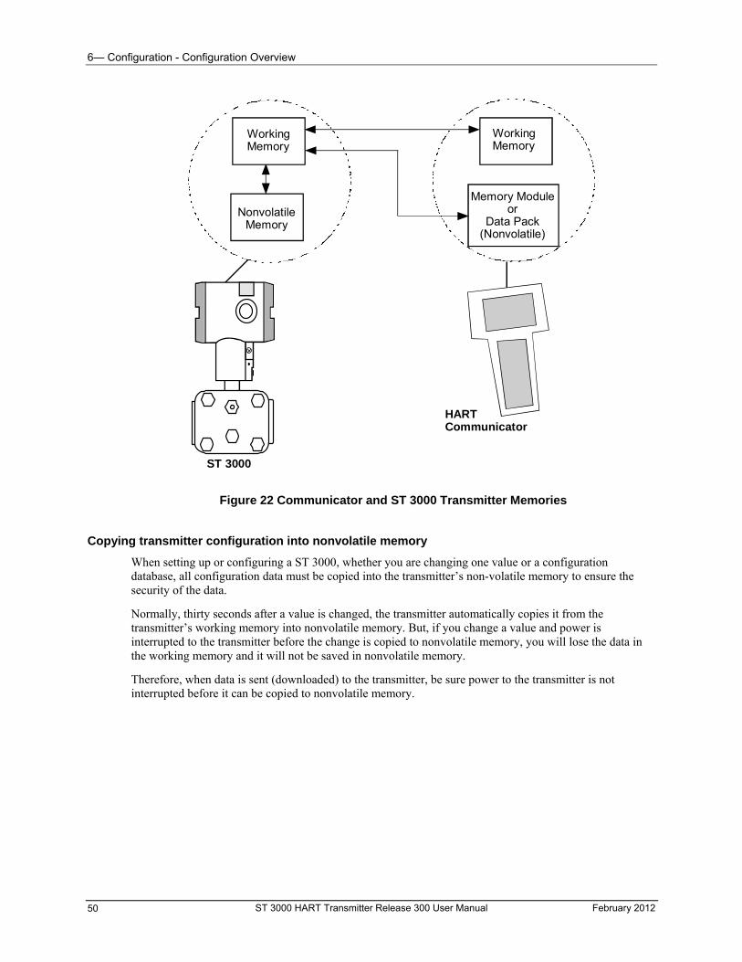
6— Configuration - Configuration Overview
WorkingMemory
WorkingMemory
NonvolatileMemory
Memory Moduleor
Data Pack(Nonvolatile)
ST 3000
HARTCommunicator
Figure 22 Communicator and ST 3000 Transmitter Memories
Copying transmitter configuration into nonvolatile memory
When setting up or configuring a ST 3000, whether you are changing one value or a configuration database, all configuration data must be copied into the transmitter’s non-volatile memory to ensure the security of the data.
Normally, thirty seconds after a value is changed, the transmitter automatically copies it from the transmitter’s working memory into nonvolatile memory. But, if you change a value and power is interrupted to the transmitter before the change is copied to nonvolatile memory, you will lose the data in the working memory and it will not be saved in nonvolatile memory.
Therefore, when data is sent (downloaded) to the transmitter, be sure power to the transmitter is not interrupted before it can be copied to nonvolatile memory.
ST 3000 HART Transmitter Release 300 User Manual February 2012 50
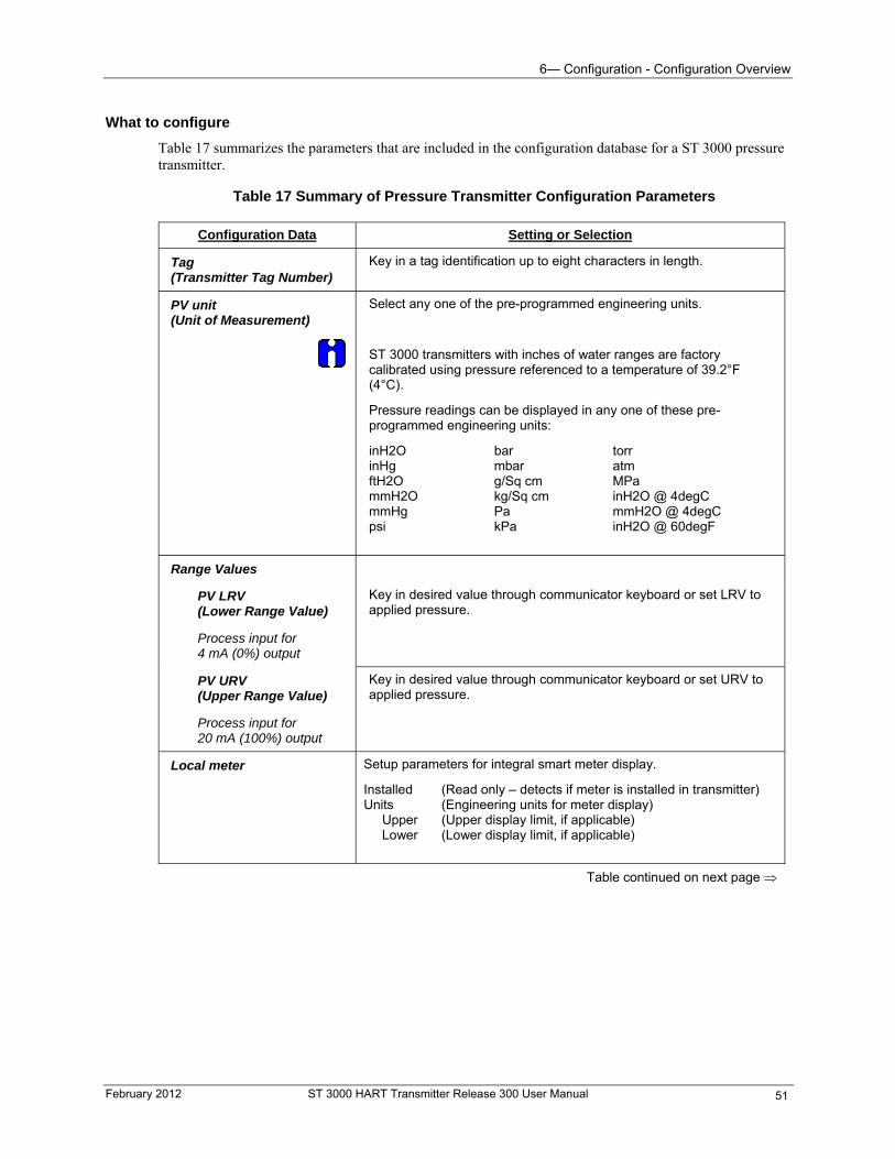
6— Configuration - Configuration Overview
What to configure
Table 17 summarizes the parameters that are included in the configuration database for a ST 3000 pressure transmitter.
Table 17 Summary of Pressure Transmitter Configuration Parameters
Configuration Data Setting or Selection
Tag (Transmitter Tag Number)
Key in a tag identification up to eight characters in length.
Select any one of the pre-programmed engineering units.
PV unit (Unit of Measurement)
ST 3000 transmitters with inches of water ranges are factory calibrated using pressure referenced to a temperature of 39.2°F (4°C).
Pressure readings can be displayed in any one of these pre-programmed engineering units:
inH2O bar torr inHg mbar atm ftH2O g/Sq cm MPa mmH2O kg/Sq cm inH2O @ 4degC mmHg Pa mmH2O @ 4degC psi kPa inH2O @ 60degF
Range Values
PV LRV (Lower Range Value)
Process input for 4 mA (0%) output
Key in desired value through communicator keyboard or set LRV to applied pressure.
PV URV (Upper Range Value)
Process input for 20 mA (100%) output
Key in desired value through communicator keyboard or set URV to applied pressure.
Local meter Setup parameters for integral smart meter display.
Installed (Read only – detects if meter is installed in transmitter) Units (Engineering units for meter display) Upper (Upper display limit, if applicable) Lower (Lower display limit, if applicable)
Table continued on next page
February 2012 ST 3000 HART Transmitter Release 300 User Manual 51
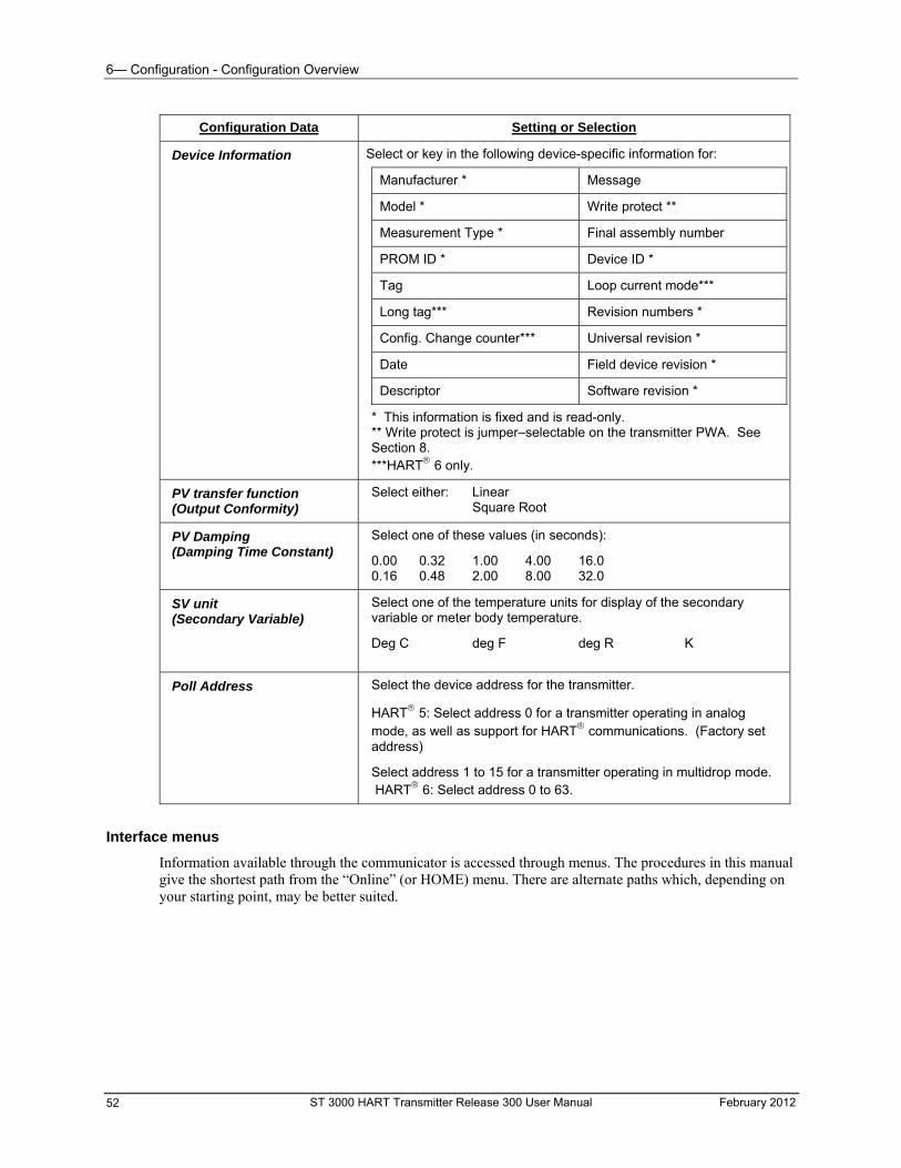
6— Configuration - Configuration Overview
Configuration Data Setting or Selection
Device Information Select or key in the following device-specific information for:
Manufacturer * Message
Model * Write protect **
Measurement Type * Final assembly number
PROM ID * Device ID *
Tag Loop current mode***
Long tag*** Revision numbers *
Config. Change counter*** Universal revision *
Date Field device revision *
Descriptor Software revision *
* This information is fixed and is read-only. ** Write protect is jumper–selectable on the transmitter PWA. See Section 8. ***HART 6 only.
PV transfer function (Output Conformity)
Select either: Linear Square Root
Select one of these values (in seconds): PV Damping (Damping Time Constant)
0.00 0.32 1.00 4.00 16.0 0.16 0.48 2.00 8.00 32.0
Select one of the temperature units for display of the secondary variable or meter body temperature.
SV unit (Secondary Variable)
Deg C deg F deg R K
Select the device address for the transmitter. Poll Address
HART 5: Select address 0 for a transmitter operating in analog mode, as well as support for HART communications. (Factory set address)
Select address 1 to 15 for a transmitter operating in multidrop mode. HART 6: Select address 0 to 63.
Interface menus
Information available through the communicator is accessed through menus. The procedures in this manual give the shortest path from the “Online” (or HOME) menu. There are alternate paths which, depending on your starting point, may be better suited.
ST 3000 HART Transmitter Release 300 User Manual February 2012 52
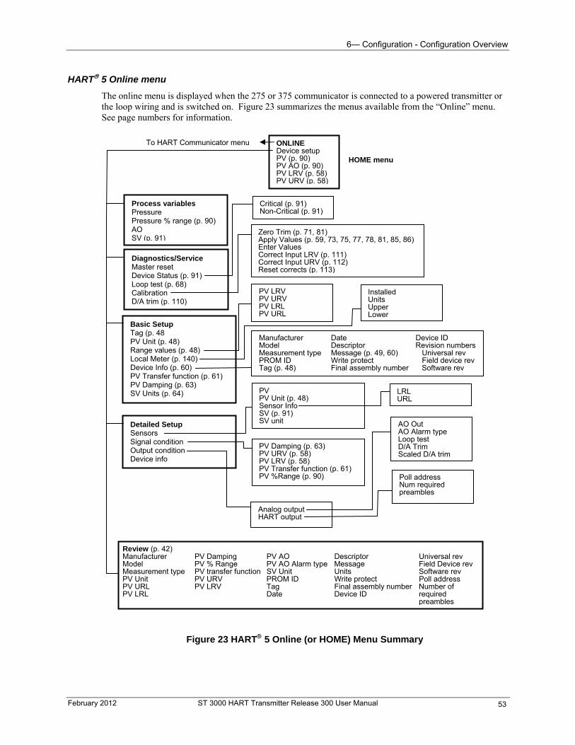
6— Configuration - Configuration Overview
HART 5 Online menu
The online menu is displayed when the 275 or 375 communicator is connected to a powered transmitter or the loop wiring and is switched on. Figure 23 summarizes the menus available from the “Online” menu. See page numbers for information.
ONLINEDevice setup PV (p. 90) PV AO (p. 90) PV LRV (p. 58) PV URV (p. 58)
Process variables Pressure Pressure % range (p. 90) AO SV (p. 91)
Diagnostics/Service Master reset Device Status (p. 91) Loop test (p. 68) Calibration D/A trim (p. 110)
Zero Trim (p. 71, 81)Apply Values (p. 59, 73, 75, 77, 78, 81, 85, 86) Enter Values Correct Input LRV (p. 111) Correct Input URV (p. 112) Reset corrects (p. 113)
Critical (p. 91)Non-Critical (p. 91)
Basic Setup Tag (p. 48 PV Unit (p. 48) Range values (p. 48) Local Meter (p. 140) Device Info (p. 60) PV Transfer function (p. 61) PV Damping (p. 63) SV Units (p. 64)
PV LRVPV URV PV LRL PV URL
InstalledUnits Upper Lower
Manufacturer Date Device ID Model Descriptor Revision numbersMeasurement type Message (p. 49, 60) Universal rev PROM ID Write protect Field device rev Tag (p. 48) Final assembly number Software rev
Detailed Setup Sensors Signal condition Output condition Device info
Analog outputHART output
AO Out AO Alarm type Loop test D/A Trim Scaled D/A trim
PV Damping (p. 63)PV URV (p. 58) PV LRV (p. 58) PV Transfer function (p. 61) PV %Range (p. 90)
PVPV Unit (p. 48) Sensor Info SV (p. 91) SV unit
Poll address Num required preambles
Review (p. 42)Manufacturer PV Damping PV AO Descriptor Universal rev Model PV % Range PV AO Alarm type Message Field Device rev Measurement type PV transfer function SV Unit Units Software rev PV Unit PV URV PROM ID Write protect Poll address PV URL PV LRV Tag Final assembly number Number of PV LRL Date Device ID required preambles
LRL URL
To HART Communicator menu
HOME menu
Figure 23 HART 5 Online (or HOME) Menu Summary
February 2012 ST 3000 HART Transmitter Release 300 User Manual 53
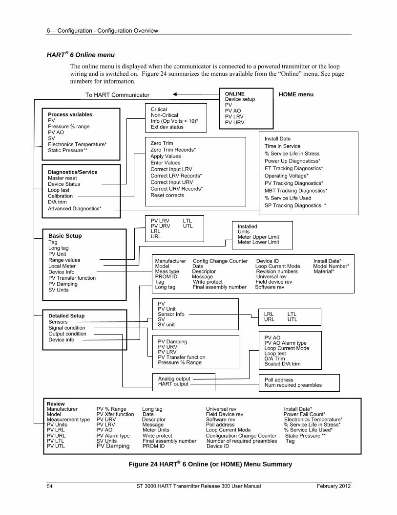
6— Configuration - Configuration Overview
HART 6 Online menu
The online menu is displayed when the communicator is connected to a powered transmitter or the loop wiring and is switched on. Figure 24 summarizes the menus available from the “Online” menu. See page numbers for information.
Figure 23a HART 6 Online (or HOME) Menu Summary
ONLINEDevice setup PV PV AO PV LRV PV URV
Process variables PV Pressure % range PV AO SV Electronics Temperature* Static Pressure**
Diagnostics/Service Master reset Device Status Loop test Calibration D/A trim Advanced Diagnostics*
Zero Trim Zero Trim Records* Apply Values Enter Values Correct Input LRV Correct LRV Records* Correct Input URV Correct URV Records* Reset corrects
Critical Non-Critical Info (Op Volts < 10)* Ext dev status
Basic Setup Tag Long tag PV Unit Range values Local Meter Device Info PV Transfer function PV Damping SV Units
PV LRV LTLPV URV UTL LRL URL
InstalledUnits Meter Upper Limit Meter Lower Limit
Manufacturer Config Change Counter Device ID Install Date* Model Date Loop Current Mode Model Number* Meas type Descriptor Revision numbers Material* PROM ID Message Universal rev Tag Write protect Field device rev Long tag Final assembly number Software rev
Detailed Setup Sensors Signal condition Output condition Device info
Analog outputHART output
PV AO PV AO Alarm type Loop Current Mode Loop test D/A Trim Scaled D/A trim
PV Damping PV URV PV LRV PV Transfer function Pressure % Range
PVPV Unit Sensor Info SV SV unit
Poll address Num required preambles
Review Manufacturer PV % Range Long tag Universal rev Install Date* Model PV Xfer function Date Field Device rev Power Fail Count* Measurement type PV URV Descriptor Software rev Electronics Temperature* PV Units PV LRV Message Poll address % Service Life in Stress* PV LRL PV AO Meter Units Loop Current Mode % Service Life Used* PV URL PV Alarm type Write protect Configuration Change Counter Static Pressure ** PV LTL SV Units Final assembly number Number of required preambles Tag PV UTL PV Damping PROM ID Device ID
LRL LTL URL UTL
MBT Tracking Diagnostics*
% Service Life Used
SP Tracking Diagnostics. *
PV Tracking Diagnostics*
Operating Voltage*
ET Tracking Diagnostics*
Power Up Diagnosticss*
% Service Life in Stress
Time in Service
Install Date
To HART Communicator HOME menu
Figure 24 HART 6 Online (or HOME) Menu Summary
ST 3000 HART Transmitter Release 300 User Manual February 2012 54
6— Configuration - Configuration Overview
Note: * next to the parameter indicates that this parameter is available only in the ST 3000 HART 6 with the following Version information:
** Future Feature to be added for DP meter body type; static pressure is 0.0 for AP and GP type meter bodies.
Universal rev: 6 Field device rev: 5 Software rev: 36
HART 5 275 or 375 Communicator menu
Figure 25 summarizes the menus available from the “HART Communicator” menu. The “HART Communicator” menu is accessed by backing out (pressing the left arrow on the keypad) from the “Online” menu.
February 2012 ST 3000 HART Transmitter Release 300 User Manual 55
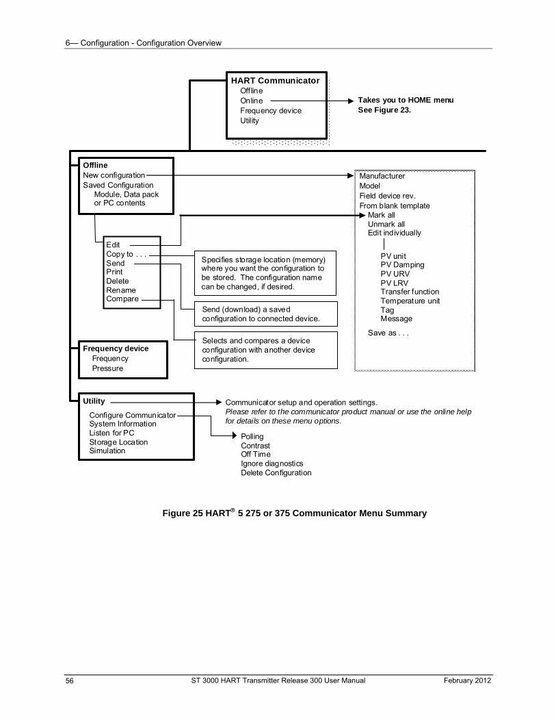
6— Configuration - Configuration Overview
Edit Copy to . . . Send Print Delete Rename Compare
HART Communicator Offline Online Frequency device Utility
Offline New configuration Saved Configuration Module, Data pack or PC contents
Manufacturer Model Field device rev. From blank template Mark all Unmark all Edit individually
PV unit PV Damping PV URV PV LRV Transfer function Temperature unit Tag Message
Takes you to HOME menuSee Figure 23.
Frequency device Frequency Pressure
Utility
Configure Communicator System Information Listen for PC Storage Location Simulation
Communicator setup and operation settings. Please refer to the communicator product manual or use the online help for details on these menu options.
Polling Contrast Off Time Ignore diagnostics Delete Configuration
Specifies storage location (memory) where you want the configuration to be stored. The configuration name can be changed, if desired.
Send (download) a saved configuration to connected device.
Selects and compares a device configuration with another device configuration.
Save as . . .
Figure 25 HART 5 275 or 375 Communicator Menu Summary
ST 3000 HART Transmitter Release 300 User Manual February 2012 56
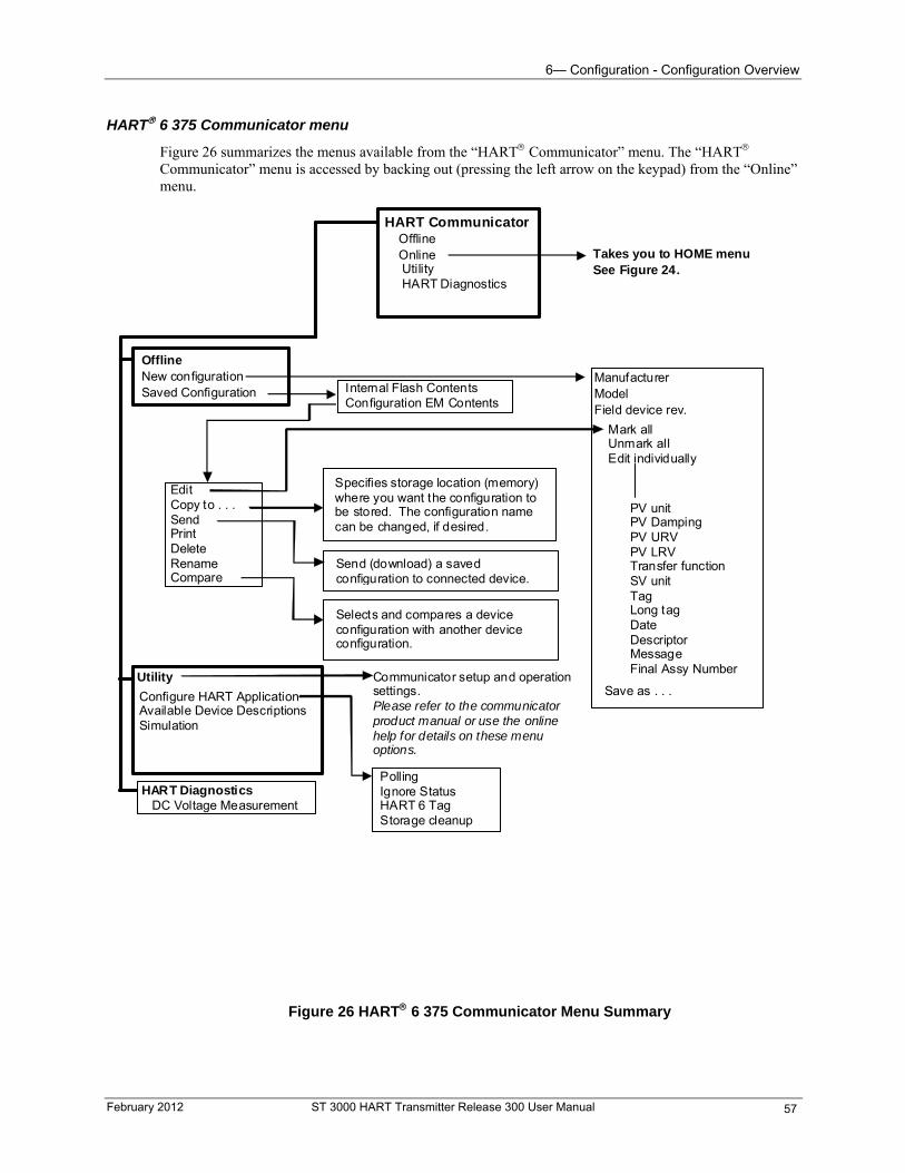
6— Configuration - Configuration Overview
HART 6 375 Communicator menu
Figure 26 summarizes the menus available from the “HART Communicator” menu. The “HART Communicator” menu is accessed by backing out (pressing the left arrow on the keypad) from the “Online” menu.
Utility Configure HART Application Available Device Descriptions Simulation
Communicator setup and operation settings. Please refer to the communicator product manual or use the online help for details on these menu options.
Polling Ignore Status HART 6 Tag Storage cleanup
Specifies storage location (memory) where you want the configuration to be stored. The configuration name can be changed, if desired.
Send (download) a saved configuration to connected device.
Selects and compares a device configuration with another device configuration.
Edit Copy to . . . Send Print Delete Rename Compare
Internal Flash Contents Configuration EM Contents
HART Diagnostics DC Voltage Measurement
Mark all Unmark all Edit individually
HART Communicator Offline Online Utility HART Diagnostics
Offline New configuration Saved Configuration
Manufacturer Model Field device rev.
PV unit PV Damping PV URV PV LRV Transfer function SV unit Tag Long tag Date Descriptor Message Final Assy Number
Takes you to HOME menuSee Figure 24.
Save as . . .
Figure 26 HART 6 375 Communicator Menu Summary
February 2012 ST 3000 HART Transmitter Release 300 User Manual 57
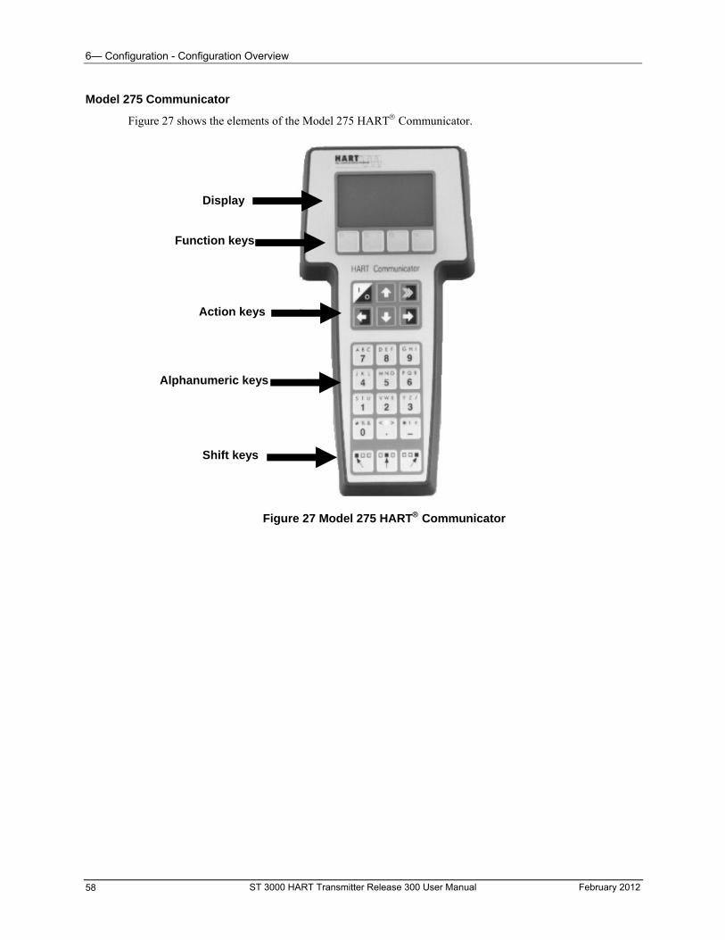
6— Configuration - Configuration Overview
Model 275 Communicator
Figure 27 shows the elements of the Model 275 HART Communicator.
Figure 27 Model 275 HART Communicator
Display
Function keys
Action keys
Alphanumeric keys
Shift keys
ST 3000 HART Transmitter Release 300 User Manual February 2012 58
6— Configuration - Configuration Overview
Model 275 Interface characteristics
Keep in mind the following display-selection descriptions when configuring a transmitter. These selections are highlighted at the bottom of the display screen, directly above the four function keys at the top of the communicator’s keypad (F1, F2, F3, and F4). To make desired highlighted selection, press the corresponding function key.
Function Key Description or Action
HOME Takes you back to the “Online” display.
EXIT Backs you out of the current display.
END Backs you out of one level to the next higher level.
ABORT Cancels a procedure backing you out of current display, and allows you to make another choice.
ESC Cancels a procedure backing you out of current display, and allows you to make another choice.
SEND Downloads the contents of the communicator’s working memory to the transmitter’s memory. Changes made in the communicator’s working memory are not transferred to the transmitter until a SEND command is issued.
If you have not sent the changes and are about to turn off the communicator, you will receive a prompt warning you that there is unsent data and asking if you want to send it before shutting off.
NEXT and PREV Allows you to scroll through a list of configured parameters.
ENTER Allows you to choose the highlighted selection or to continue after performing an action, such as removing the loop from automatic control.
HELP Gives a brief definition/explanation of the current selection or display.
DEL Deletes character directly beneath flashing cursor.
Symbols
Symbol Description or Action
♥ Flashing heart icon in the upper right corner of display screen indicates that the transmitter and communicator are “talking.”
When this symbol appears on the display screen it indicates that you can press the left arrow on the keypad to back out to another display.
These arrows appear on the display screen to indicate there is more information to scroll through, using the indicated arrow on the keypad. and/or
This arrow appears on the display screen to indicate that a menu item contains more information that can be accessed by pressing the right arrow on the keypad.
[>>>] This “hot” key on the keypad allows you to access range values (LRV, URV, LRL, and URL) directly. When finished, you return to the spot from which you started.
ATTENTION
An alternate way of selecting a menu item, besides using the up and down arrows, is to press the key corresponding to the number left of the desired menu item.
February 2012 ST 3000 HART Transmitter Release 300 User Manual 59
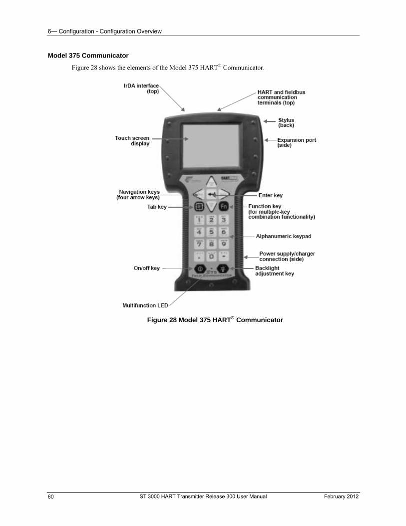
6— Configuration - Configuration Overview
Model 375 Communicator
Figure 28 shows the elements of the Model 375 HART Communicator.
Figure 28 Model 375 HART Communicator
ST 3000 HART Transmitter Release 300 User Manual February 2012 60
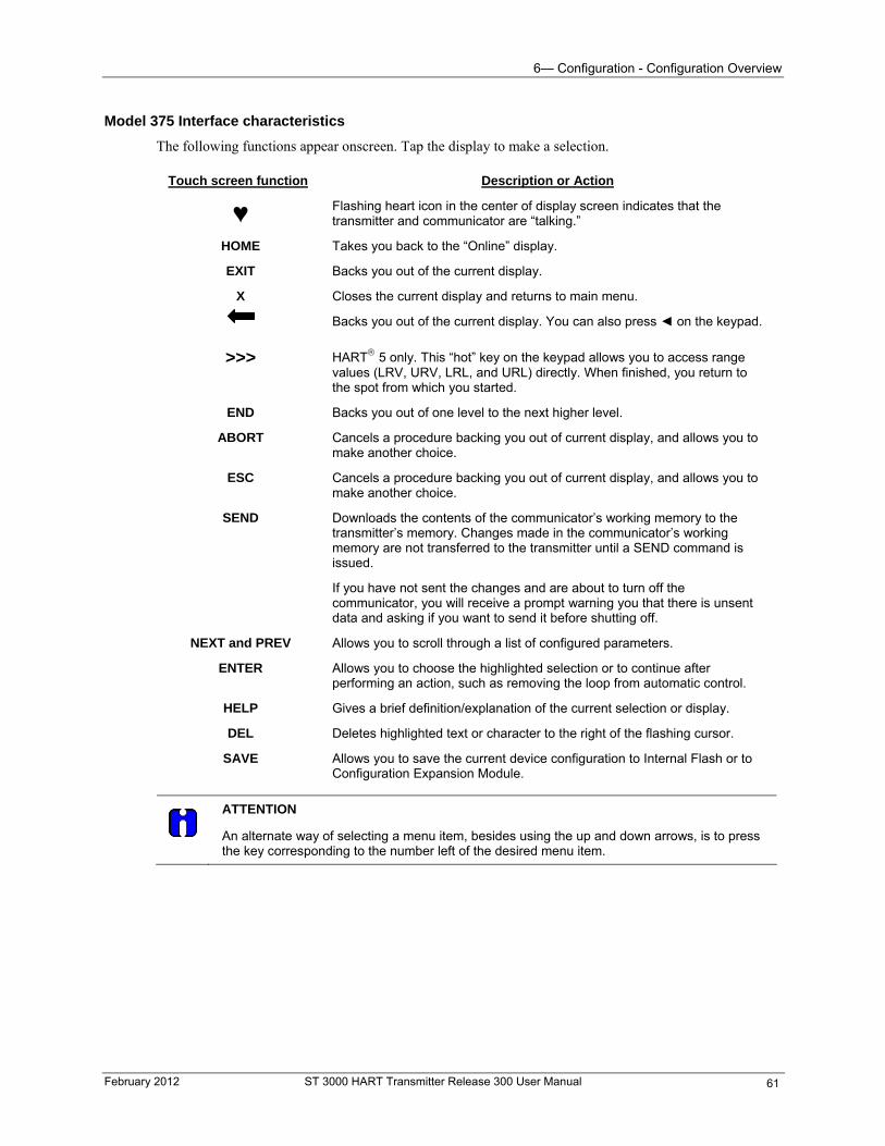
6— Configuration - Configuration Overview
Model 375 Interface characteristics
The following functions appear onscreen. Tap the display to make a selection.
Touch screen function Description or Action
♥ Flashing heart icon in the center of display screen indicates that the transmitter and communicator are “talking.”
HOME Takes you back to the “Online” display.
EXIT Backs you out of the current display.
X Closes the current display and returns to main menu.
Backs you out of the current display. You can also press on the keypad.
>>> HART 5 only. This “hot” key on the keypad allows you to access range values (LRV, URV, LRL, and URL) directly. When finished, you return to the spot from which you started.
END Backs you out of one level to the next higher level.
ABORT Cancels a procedure backing you out of current display, and allows you to make another choice.
ESC Cancels a procedure backing you out of current display, and allows you to make another choice.
SEND Downloads the contents of the communicator’s working memory to the transmitter’s memory. Changes made in the communicator’s working memory are not transferred to the transmitter until a SEND command is issued.
If you have not sent the changes and are about to turn off the communicator, you will receive a prompt warning you that there is unsent data and asking if you want to send it before shutting off.
NEXT and PREV Allows you to scroll through a list of configured parameters.
ENTER Allows you to choose the highlighted selection or to continue after performing an action, such as removing the loop from automatic control.
HELP Gives a brief definition/explanation of the current selection or display.
DEL Deletes highlighted text or character to the right of the flashing cursor.
SAVE Allows you to save the current device configuration to Internal Flash or to Configuration Expansion Module.
ATTENTION
An alternate way of selecting a menu item, besides using the up and down arrows, is to press the key corresponding to the number left of the desired menu item.
February 2012 ST 3000 HART Transmitter Release 300 User Manual 61
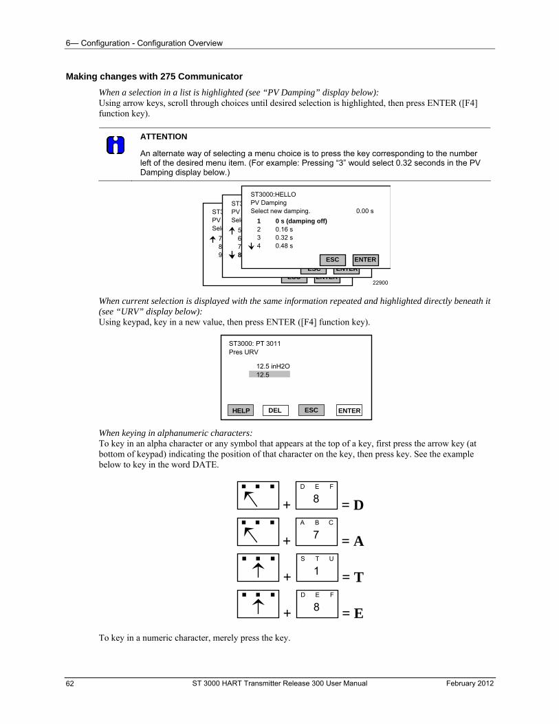
6— Configuration - Configuration Overview
Making changes with 275 Communicator
When a selection in a list is highlighted (see “PV Damping” display below): Using arrow keys, scroll through choices until desired selection is highlighted, then press ENTER ([F4] function key).
ATTENTION
An alternate way of selecting a menu choice is to press the key corresponding to the number left of the desired menu item. (For example: Pressing “3” would select 0.32 seconds in the PV Damping display below.)
ST3000:HELLO PV Damping Select new damping.
ENTERESC
4.00 s 8.00 s 16.0 s 32.0 s
7 8 9
0.00 s
ST3000:HELLO PV Damping Select new damping.
ENTERESC
1.00 s 2.00 s 4.00 s 8.00 s
5 6 7 8
0.00 s
ST3000:HELLO PV Damping Select new damping.
ENTERESC
0 s (damping off) 0.16 s 0.32 s 0.48 s
1 2 3 4
0.00 s
22900
When current selection is displayed with the same information repeated and highlighted directly beneath it (see “URV” display below): Using keypad, key in a new value, then press ENTER ([F4] function key).
ST3000: PT 3011 Pres URV
12.5 inH2O12.5
HELP DEL ESC ENTER
When keying in alphanumeric characters: To key in an alpha character or any symbol that appears at the top of a key, first press the arrow key (at bottom of keypad) indicating the position of that character on the key, then press key. See the example below to key in the word DATE.
+ 8D E F
= D
+ 7A B C
= A
+ 1S T U
= T
+ 8D E F
= E
To key in a numeric character, merely press the key.
ST 3000 HART Transmitter Release 300 User Manual February 2012 62
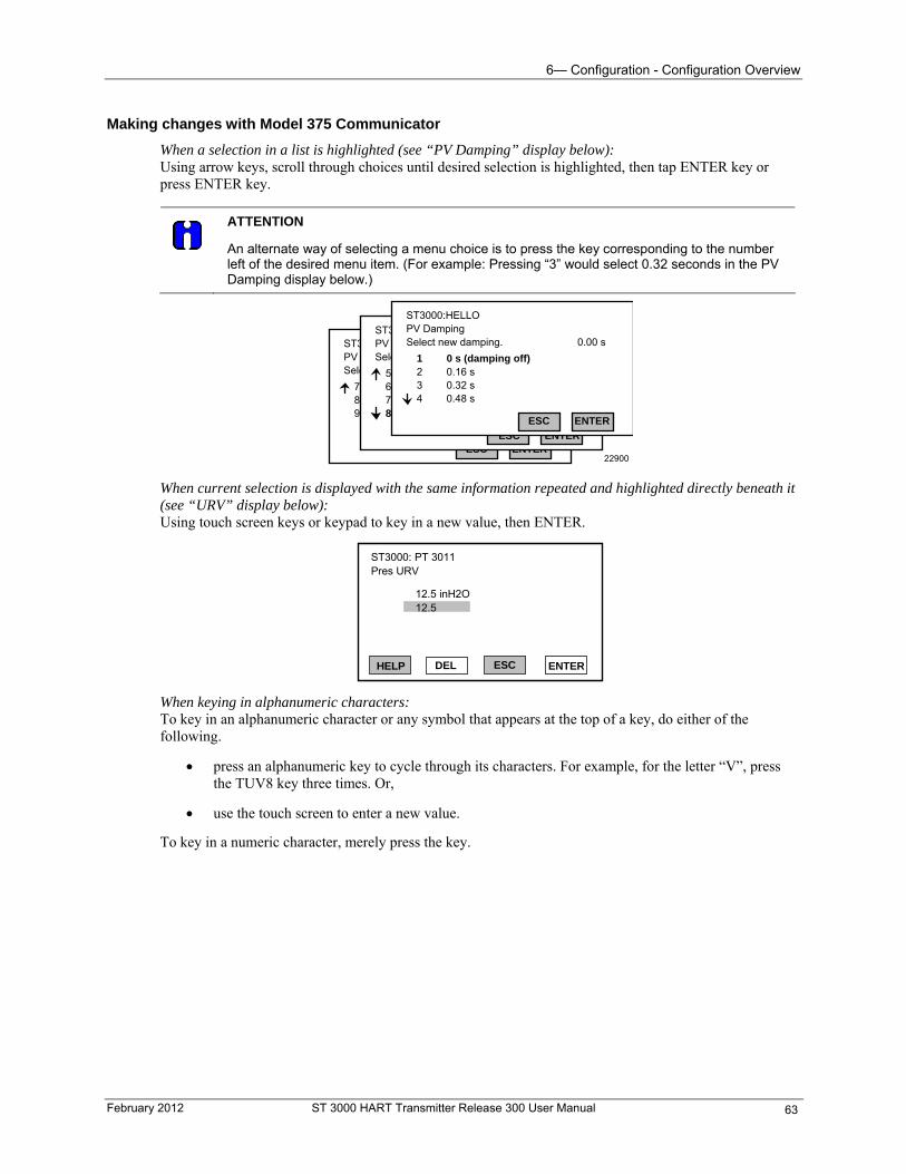
6— Configuration - Configuration Overview
Making changes with Model 375 Communicator
When a selection in a list is highlighted (see “PV Damping” display below): Using arrow keys, scroll through choices until desired selection is highlighted, then tap ENTER key or press ENTER key.
ATTENTION
An alternate way of selecting a menu choice is to press the key corresponding to the number left of the desired menu item. (For example: Pressing “3” would select 0.32 seconds in the PV Damping display below.)
ST3000:HELLO PV Damping Select new damping.
ENTERESC
4.00 s 8.00 s 16.0 s 32.0 s
7 8 9
0.00 s
ST3000:HELLO PV Damping Select new damping.
ENTERESC
1.00 s 2.00 s 4.00 s 8.00 s
5 6 7 8
0.00 s
ST3000:HELLO PV Damping Select new damping.
ENTERESC
0 s (damping off) 0.16 s 0.32 s 0.48 s
1 2 3 4
0.00 s
22900
When current selection is displayed with the same information repeated and highlighted directly beneath it (see “URV” display below): Using touch screen keys or keypad to key in a new value, then ENTER.
ST3000: PT 3011 Pres URV
12.5 inH2O12.5
HELP DEL ESC ENTER
When keying in alphanumeric characters: To key in an alphanumeric character or any symbol that appears at the top of a key, do either of the following.
press an alphanumeric key to cycle through its characters. For example, for the letter “V”, press the TUV8 key three times. Or,
use the touch screen to enter a new value.
To key in a numeric character, merely press the key.
February 2012 ST 3000 HART Transmitter Release 300 User Manual 63
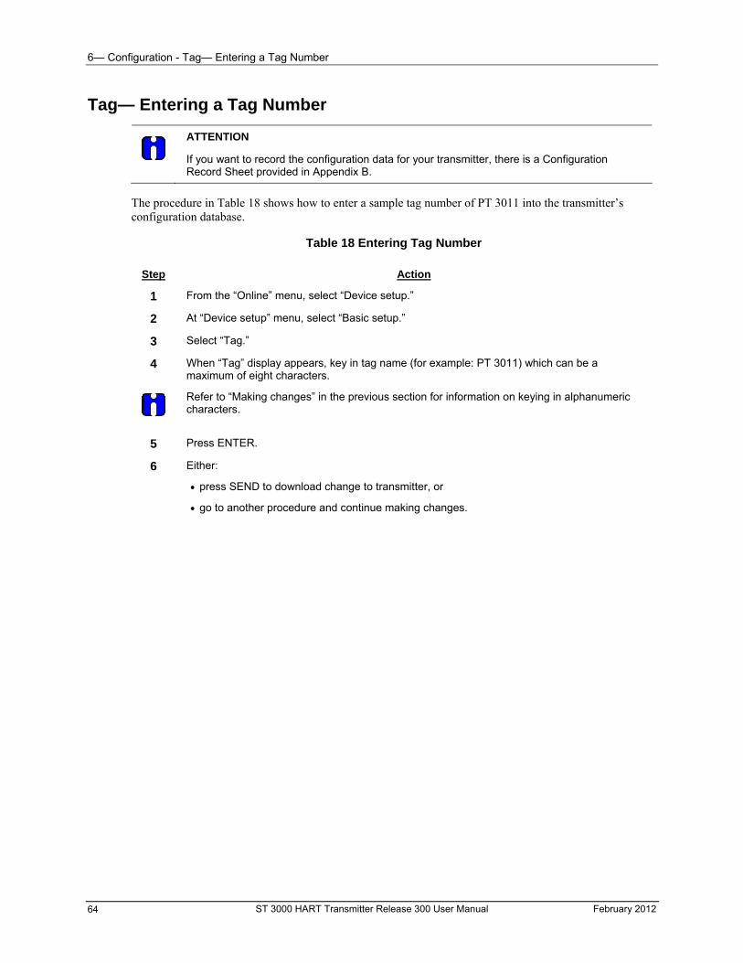
6— Configuration - Tag— Entering a Tag Number
ST 3000 HART Transmitter Release 300 User Manual February 2012 64
Tag— Entering a Tag Number
ATTENTION
If you want to record the configuration data for your transmitter, there is a Configuration Record Sheet provided in Appendix B.
The procedure in Table 18 shows how to enter a sample tag number of PT 3011 into the transmitter’s configuration database.
Table 18 Entering Tag Number
Step Action
1 From the “Online” menu, select “Device setup.”
2 At “Device setup” menu, select “Basic setup.”
3 Select “Tag.”
4
When “Tag” display appears, key in tag name (for example: PT 3011) which can be a maximum of eight characters.
Refer to “Making changes” in the previous section for information on keying in alphanumeric characters.
5 Press ENTER.
6 Either:
press SEND to download change to transmitter, or
go to another procedure and continue making changes.
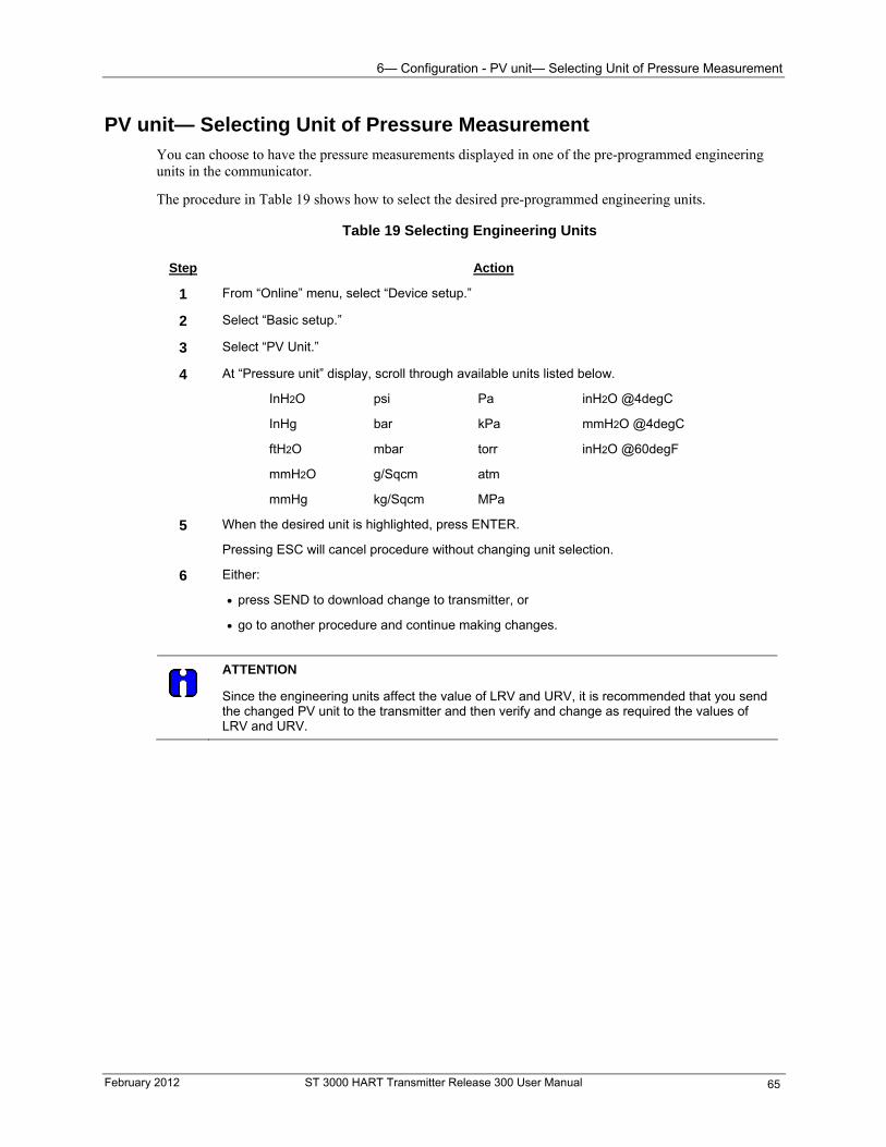
6— Configuration - PV unit— Selecting Unit of Pressure Measurement
February 2012 ST 3000 HART Transmitter Release 300 User Manual 65
PV unit— Selecting Unit of Pressure Measurement You can choose to have the pressure measurements displayed in one of the pre-programmed engineering units in the communicator.
The procedure in Table 19 shows how to select the desired pre-programmed engineering units.
Table 19 Selecting Engineering Units
Step Action
1 From “Online” menu, select “Device setup.”
2 Select “Basic setup.”
3 Select “PV Unit.”
4 At “Pressure unit” display, scroll through available units listed below.
InH2O psi Pa inH2O @4degC
InHg bar kPa mmH2O @4degC
ftH2O mbar torr inH2O @60degF
mmH2O g/Sqcm atm
mmHg kg/Sqcm MPa
5 When the desired unit is highlighted, press ENTER.
Pressing ESC will cancel procedure without changing unit selection.
6 Either:
press SEND to download change to transmitter, or
go to another procedure and continue making changes.
ATTENTION
Since the engineering units affect the value of LRV and URV, it is recommended that you send the changed PV unit to the transmitter and then verify and change as required the values of LRV and URV.
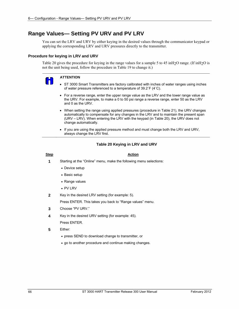
6— Configuration - Range Values— Setting PV URV and PV LRV
ST 3000 HART Transmitter Release 300 User Manual February 2012 66
Range Values— Setting PV URV and PV LRV You can set the LRV and URV by either keying in the desired values through the communicator keypad or applying the corresponding LRV and URV pressures directly to the transmitter.
Procedure for keying in LRV and URV
Table 20 gives the procedure for keying in the range values for a sample 5 to 45 inH2O range. (If inH2O is not the unit being used, follow the procedure in Table 19 to change it.)
ATTENTION
ST 3000 Smart Transmitters are factory calibrated with inches of water ranges using inches of water pressure referenced to a temperature of 39.2˚F (4˚C).
For a reverse range, enter the upper range value as the LRV and the lower range value as the URV. For example, to make a 0 to 50 psi range a reverse range, enter 50 as the LRV and 0 as the URV.
When setting the range using applied pressures (procedure in Table 21), the URV changes automatically to compensate for any changes in the LRV and to maintain the present span (URV – LRV). When entering the LRV with the keypad (in Table 20), the URV does not change automatically.
If you are using the applied pressure method and must change both the LRV and URV, always change the LRV first.
Table 20 Keying in LRV and URV
Step Action
1 Starting at the “Online” menu, make the following menu selections:
Device setup
Basic setup
Range values
PV LRV
2 Key in the desired LRV setting (for example: 5).
Press ENTER. This takes you back to “Range values” menu.
3 Choose “PV URV.”
4 Key in the desired URV setting (for example: 45).
Press ENTER.
5 Either:
press SEND to download change to transmitter, or
go to another procedure and continue making changes.
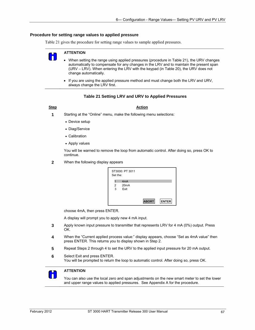
6— Configuration - Range Values— Setting PV URV and PV LRV
February 2012 ST 3000 HART Transmitter Release 300 User Manual 67
Procedure for setting range values to applied pressure
Table 21 gives the procedure for setting range values to sample applied pressures.
ATTENTION
When setting the range using applied pressures (procedure in Table 21), the URV changes automatically to compensate for any changes in the LRV and to maintain the present span (URV – LRV). When entering the LRV with the keypad (in Table 20), the URV does not change automatically.
If you are using the applied pressure method and must change both the LRV and URV, always change the LRV first.
Table 21 Setting LRV and URV to Applied Pressures
Step Action
1 Starting at the “Online” menu, make the following menu selections:
Device setup
Diag/Service
Calibration
Apply values
You will be warned to remove the loop from automatic control. After doing so, press OK to continue.
2 When the following display appears
ST3000: PT 3011 Set the:
1 4mA2 20mA
ABORT ENTER
3 Exit
choose 4mA, then press ENTER.
A display will prompt you to apply new 4 mA input.
3 Apply known input pressure to transmitter that represents LRV for 4 mA (0%) output. Press OK.
4 When the “Current applied process value:” display appears, choose “Set as 4mA value” then press ENTER. This returns you to display shown in Step 2.
5 Repeat Steps 2 through 4 to set the URV to the applied input pressure for 20 mA output.
6 Select Exit and press ENTER. You will be prompted to return the loop to automatic control. After doing so, press OK.
ATTENTION
You can also use the local zero and span adjustments on the new smart meter to set the lower and upper range values to applied pressures. See Appendix A for the procedure.
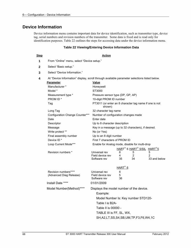
6— Configuration - Device Information
Device Information Device information menu contains important data for device identification, such as transmitter type, device tag, serial numbers and revision numbers of the transmitter. Some data is fixed and is read only for identification purposes. Table 22 outlines the steps for accessing data under the device information menu.
Table 22 Viewing/Entering Device Information Data
Step Action
1 From “Online” menu, select “Device setup.”
2 Select “Basic setup.”
3 Select “Device Information.”
4 At “Device Information” display, scroll through available parameter selections listed below.
Parameter Value
Manufacturer * Honeywell
Model * ST3000
Measurement type * Pressure sensor type (DP, GP, AP)
PROM ID * 10-digit PROM ID number
Tag PT3011 (or enter an 8 character tag name if one is not shown)
Long Tag 32 character tag name
Configuration Change Counter*** Number of configuration changes made
Date Enter date
Descriptor Up to 8 character description
Message Key in a message (up to 32 characters), if desired.
Write protect ** No (or Yes)
Final assembly number Up to an 8 digit number
Device ID * First 7 characters of PROM ID
Loop Current Mode*** Enable for Analog mode, disable for multi-drop
HART 6 HART 5/SIL HART5 Revision numbers * Universal rev 6 5 5 Field device rev 4 2 2 Software rev 35 34 33 and below
HART 6
Revision numbers**** Universal rev 6 (Advanced Diag Release) Field device rev 5 Software rev 36
Install Date **** 01/01/2009
Model Number(Method)**** Displays the model number of the device.
Example:
Model Number Is: Key number STD120-
Table I is B2A-
Table II is 00000 -
TABLE III is FF, SL, WX,
SH,A2,LT,SS,S4,SB,UM,TP,F3,F6,W4,1C
ST 3000 HART Transmitter Release 300 User Manual February 2012 68
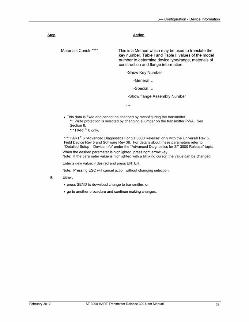
6— Configuration - Device Information
February 2012 ST 3000 HART Transmitter Release 300 User Manual 69
Step Action
Materials Constr **** This is a Method which may be used to translate the key number, Table I and Table II values of the model number to determine device type/range, materials of construction and flange information.
-Show Key Number
-General…
-Special …
-Show flange Assembly Number
…
This data is fixed and cannot be changed by reconfiguring the transmitter. ** Write protection is selected by changing a jumper on the transmitter PWA. See Section 8. *** HART 6 only.
****HART 6 “Advanced Diagnostics For ST 3000 Release” only with the Universal Rev 6, Field Device Rev 5 and Software Rev 36. For details about these parameters refer to “Detailed Setup – Device Info” under the “Advanced Diagnostics for ST 3000 Release” topic.
When the desired parameter is highlighted, press right arrow key. Note: If the parameter value is highlighted with a blinking cursor, the value can be changed.
Enter a new value, if desired and press ENTER.
Note: Pressing ESC will cancel action without changing selection.
5 Either:
press SEND to download change to transmitter, or
go to another procedure and continue making changes.
6— Configuration - Device Information
ST 3000 HART Transmitter Release 300 User Manual February 2012 70
Pressure transfer function— Selecting Output Conformity
Output form options
You can select the transmitter’s output to represent either a straight linear calculation, or a square root calculation for flow measurement applications using a differential pressure type transmitter. Thus, we refer to the linear or the square root selection as the output conformity or the output form.
The procedure in Table 23 shows how to select the desired Output conformity.
Table 23 Selecting Output Conformity
Step Action
1 From “Online” menu, select “Device setup.”
2 Select “Basic setup.”
3 Select “PV xfer fnctn.”
4 Select either Linear or Square root, then press ENTER.
5 Either:
press SEND to download change to transmitter, or
go to another procedure and continue making changes.
About square root output
For differential pressure transmitters measuring the pressure drop across a primary element, the flow rate is directly proportional to the square root of the differential or pressure drop. The ST 3000 transmitter’s output is automatically converted to equal percent of flow when its output conformity is configured as square root.
You can use these formulas to manually calculate the percent of flow for comparison purposes. (Note: This formula assumes that LRV = 0.)
∆P
Span • 100 = %P
Where, ∆P = Differential pressure input in engineering units
Span = Transmitter’s measurement span (URV – LRV)
%P = Pressure input in percent of span
Therefore, %P100 • 100 = % Flow
And, you can use this formula to determine the corresponding current output in milliamperes direct current.
(% Flow • 16 mA) + 4 mA = mA dc Output
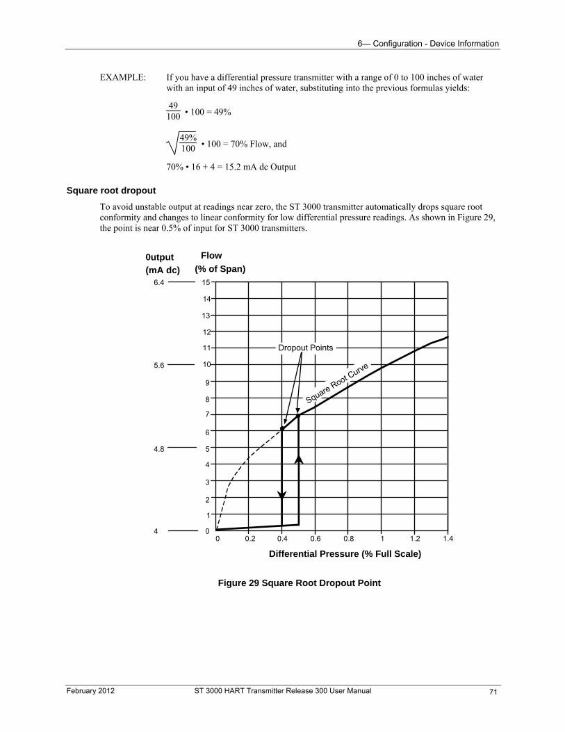
6— Configuration - Device Information
EXAMPLE: If you have a differential pressure transmitter with a range of 0 to 100 inches of water with an input of 49 inches of water, substituting into the previous formulas yields:
49100 • 100 = 49%
49%100 • 100 = 70% Flow, and
70% • 16 + 4 = 15.2 mA dc Output
Square root dropout
To avoid unstable output at readings near zero, the ST 3000 transmitter automatically drops square root conformity and changes to linear conformity for low differential pressure readings. As shown in Figure 29, the point is near 0.5% of input for ST 3000 transmitters.
0 0.2 0.4 0.8 10.6 1.2 1.4
1
2
3
4
5
6
7
8
9
10
11
12
13
14
15
0
Differential Pressure (% Full Scale)
Flow
(% of Span)0utput
(mA dc)
4
4.8
5.6
6.4
Dropout Points
Square Root Curve
Figure 29 Square Root Dropout Point
February 2012 ST 3000 HART Transmitter Release 300 User Manual 71
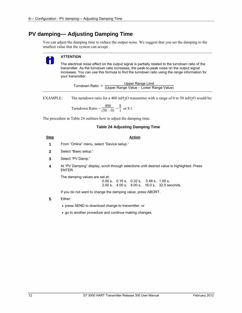
6— Configuration - PV damping— Adjusting Damping Time
ST 3000 HART Transmitter Release 300 User Manual February 2012 72
PV damping— Adjusting Damping Time You can adjust the damping time to reduce the output noise. We suggest that you set the damping to the smallest value that the system can accept.
ATTENTION
The electrical noise effect on the output signal is partially related to the turndown ratio of the transmitter. As the turndown ratio increases, the peak-to-peak noise on the output signal increases. You can use this formula to find the turndown ratio using the range information for your transmitter.
Turndown Ratio = Upper Range Limit
(Upper Range Value – Lower Range Value)
EXAMPLE: The turndown ratio for a 400 inH2O transmitter with a range of 0 to 50 inH2O would be:
Turndown Ratio = 400
(50 – 0) = 81 or 8:1
The procedure in Table 24 outlines how to adjust the damping time.
Table 24 Adjusting Damping Time
Step Action
1 From “Online” menu, select “Device setup.”
2 Select “Basic setup.”
3 Select “PV Damp.”
4 At “PV Damping” display, scroll through selections until desired value is highlighted. Press ENTER.
The damping values are set at: 0.00 s, 0.16 s, 0.32 s, 0.48 s, 1.00 s, 2.00 s, 4.00 s, 8.00 s, 16.0 s, 32.0 seconds.
If you do not want to change the damping value, press ABORT.
5 Either:
press SEND to download change to transmitter, or
go to another procedure and continue making changes.
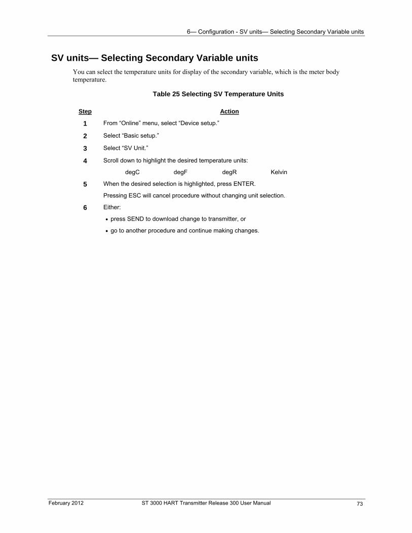
6— Configuration - SV units— Selecting Secondary Variable units
February 2012 ST 3000 HART Transmitter Release 300 User Manual 73
SV units— Selecting Secondary Variable units You can select the temperature units for display of the secondary variable, which is the meter body temperature.
Table 25 Selecting SV Temperature Units
Step Action
1 From “Online” menu, select “Device setup.”
2 Select “Basic setup.”
3 Select “SV Unit.”
4 Scroll down to highlight the desired temperature units:
degC degF degR Kelvin
5 When the desired selection is highlighted, press ENTER.
Pressing ESC will cancel procedure without changing unit selection.
6 Either:
press SEND to download change to transmitter, or
go to another procedure and continue making changes.
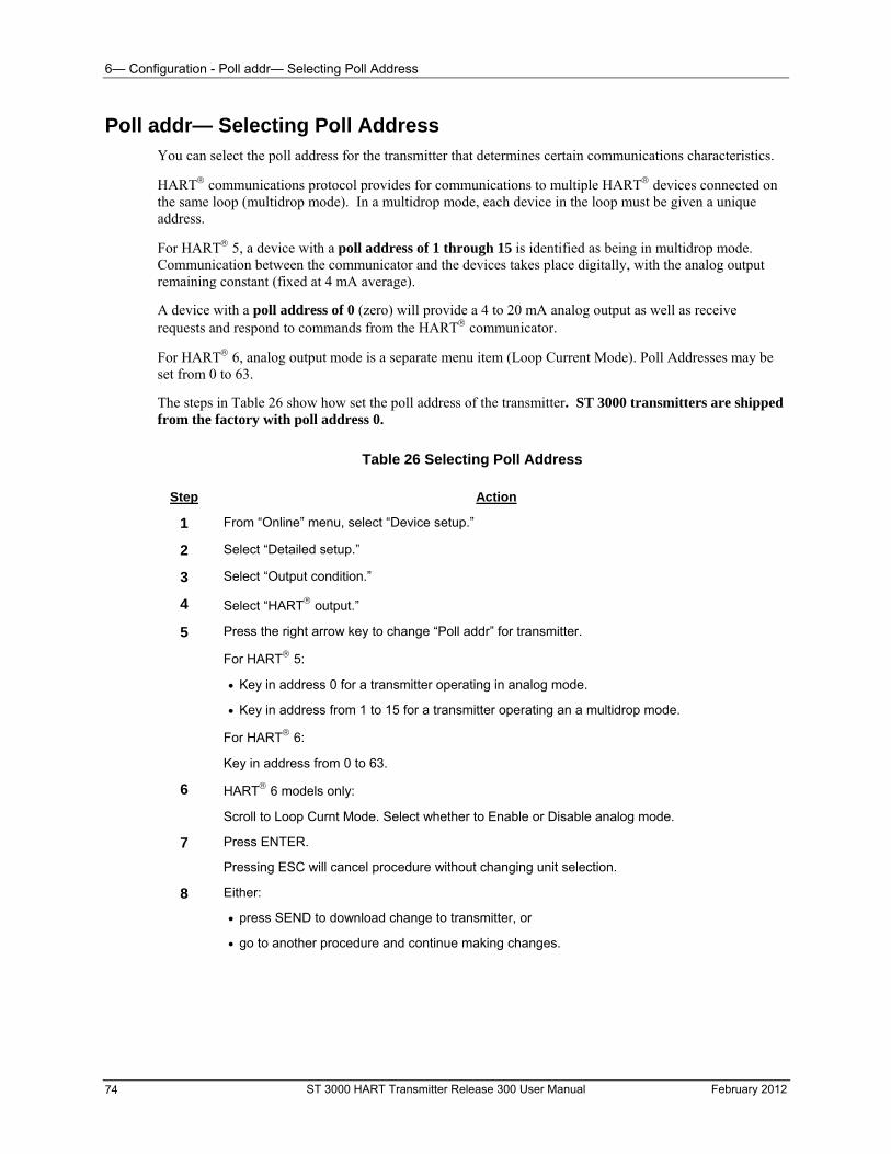
6— Configuration - Poll addr— Selecting Poll Address
ST 3000 HART Transmitter Release 300 User Manual February 2012 74
Poll addr— Selecting Poll Address You can select the poll address for the transmitter that determines certain communications characteristics.
HART communications protocol provides for communications to multiple HART devices connected on the same loop (multidrop mode). In a multidrop mode, each device in the loop must be given a unique address.
For HART 5, a device with a poll address of 1 through 15 is identified as being in multidrop mode. Communication between the communicator and the devices takes place digitally, with the analog output remaining constant (fixed at 4 mA average).
A device with a poll address of 0 (zero) will provide a 4 to 20 mA analog output as well as receive requests and respond to commands from the HART communicator.
For HART 6, analog output mode is a separate menu item (Loop Current Mode). Poll Addresses may be set from 0 to 63.
The steps in Table 26 show how set the poll address of the transmitter. ST 3000 transmitters are shipped from the factory with poll address 0.
Table 26 Selecting Poll Address
Step Action
1 From “Online” menu, select “Device setup.”
2 Select “Detailed setup.”
3 Select “Output condition.”
4 Select “HART output.”
5 Press the right arrow key to change “Poll addr” for transmitter.
For HART 5:
Key in address 0 for a transmitter operating in analog mode.
Key in address from 1 to 15 for a transmitter operating an a multidrop mode.
For HART 6:
Key in address from 0 to 63.
6 HART 6 models only:
Scroll to Loop Curnt Mode. Select whether to Enable or Disable analog mode.
7 Press ENTER.
Pressing ESC will cancel procedure without changing unit selection.
8 Either:
press SEND to download change to transmitter, or
go to another procedure and continue making changes.
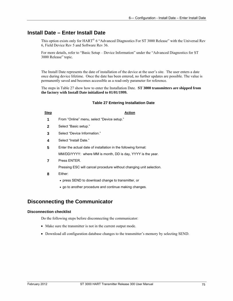
6— Configuration - Install Date – Enter Install Date
February 2012 ST 3000 HART Transmitter Release 300 User Manual 75
Install Date – Enter Install Date
This option exists only for HART 6 “Advanced Diagnostics For ST 3000 Release” with the Universal Rev 6, Field Device Rev 5 and Software Rev 36.
For more details, refer to “Basic Setup – Device Information” under the “Advanced Diagnostics for ST 3000 Release” topic.
The Install Date represents the date of installation of the device at the user’s site. The user enters a date once during device lifetime. Once the date has been entered, no further updates are possible. The value is permanently saved and becomes accessible as a read-only parameter for reference.
The steps in Table 27 show how to enter the Installation Date. ST 3000 transmitters are shipped from the factory with Install Date initialized to 01/01/1999.
Table 27 Entering Installation Date
Step Action
1 From “Online” menu, select “Device setup.”
2 Select “Basic setup.”
3 Select “Device Information.”
4 Select “Install Date.”
5 Enter the actual date of installation in the following format:
MM/DD/YYYY: where MM is month, DD is day, YYYY is the year.
7 Press ENTER.
Pressing ESC will cancel procedure without changing unit selection.
8 Either:
press SEND to download change to transmitter, or
go to another procedure and continue making changes.
Disconnecting the Communicator
Disconnection checklist
Do the following steps before disconnecting the communicator:
Make sure the transmitter is not in the current output mode.
Download all configuration database changes to the transmitter’s memory by selecting SEND.
7— Start-up - Overview
7— Start-up
Overview
About this section
This section identifies typical start-up tasks associated with several generic pressure measurement applications. It also includes the procedure for running an optional analog output check.
This section includes these topics.
Performing an analog output check
Start up procedures for the different types of pressure transmitters in various applications, such as
DP transmitter in a flow measurement
DP transmitter in a pressure measurement
DP transmitter in a liquid level measurement applications
GP transmitter in pressure or liquid level measurement applications
AP transmitter in a pressure measurement
DP transmitter with remote diaphragm seals in a liquid level measurement application
ATTENTION
All procedures in this manual assume a transmitter poll address of 0 (zero). See Section 6, for information about poll address.
ST 3000 HART Transmitter Release 300 User Manual February 2012 76
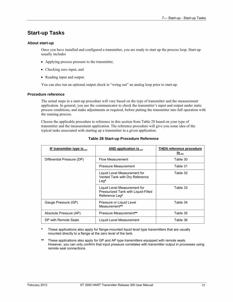
7— Start-up - Start-up Tasks
Start-up Tasks
About start-up
Once you have installed and configured a transmitter, you are ready to start up the process loop. Start-up usually includes
Applying process pressure to the transmitter,
Checking zero input, and
Reading input and output.
You can also run an optional output check to “wring out” an analog loop prior to start-up.
Procedure reference
The actual steps in a start-up procedure will vary based on the type of transmitter and the measurement application. In general, you use the communicator to check the transmitter’s input and output under static process conditions, and make adjustments as required, before putting the transmitter into full operation with the running process.
Choose the applicable procedure to reference in this section from Table 28 based on your type of transmitter and the measurement application. The reference procedure will give you some idea of the typical tasks associated with starting up a transmitter in a given application.
Table 28 Start-up Procedure Reference
IF transmitter type is ... AND application is ... THEN reference procedure in ...
Differential Pressure (DP) Flow Measurement Table 30
Pressure Measurement Table 31
Liquid Level Measurement for Vented Tank with Dry Reference Leg*
Table 32
Liquid Level Measurement for Pressurized Tank with Liquid-Filled Reference Leg*
Table 33
Gauge Pressure (GP) Pressure or Liquid Level Measurement**
Table 34
Pressure Measurement** Absolute Pressure (AP) Table 35
DP with Remote Seals Liquid Level Measurement Table 36
* These applications also apply for flange-mounted liquid level type transmitters that are usually mounted directly to a flange at the zero level of the tank.
** These applications also apply for GP and AP type transmitters equipped with remote seals. However, you can only confirm that input pressure correlates with transmitter output in processes using remote seal connections.
February 2012 ST 3000 HART Transmitter Release 300 User Manual 77
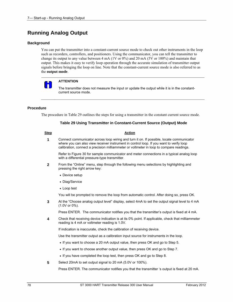
7— Start-up - Running Analog Output
ST 3000 HART Transmitter Release 300 User Manual February 2012 78
Running Analog Output
Background
You can put the transmitter into a constant-current source mode to check out other instruments in the loop such as recorders, controllers, and positioners. Using the communicator, you can tell the transmitter to change its output to any value between 4 mA (1V or 0%) and 20 mA (5V or 100%) and maintain that output. This makes it easy to verify loop operation through the accurate simulation of transmitter output signals before bringing the loop on line. Note that the constant-current source mode is also referred to as the output mode.
ATTENTION
The transmitter does not measure the input or update the output while it is in the constant-current source mode.
Procedure
The procedure in Table 29 outlines the steps for using a transmitter in the constant current source mode.
Table 29 Using Transmitter in Constant-Current Source (Output) Mode
Step Action
1 Connect communicator across loop wiring and turn it on. If possible, locate communicator where you can also view receiver instrument in control loop. If you want to verify loop calibration, connect a precision milliammeter or voltmeter in loop to compare readings.
Refer to Figure 30 for sample communicator and meter connections in a typical analog loop with a differential pressure-type transmitter.
2 From the “Online” menu, step through the following menu selections by highlighting and pressing the right arrow key:
Device setup
Diag/Service
Loop test
You will be prompted to remove the loop from automatic control. After doing so, press OK.
3 At the “Choose analog output level” display, select 4mA to set the output signal level to 4 mA (1.0V or 0%).
Press ENTER. The communicator notifies you that the transmitter’s output is fixed at 4 mA.
4 Check that receiving device indication is at its 0% point. If applicable, check that milliammeter reading is 4 mA or voltmeter reading is 1.0V.
If indication is inaccurate, check the calibration of receiving device.
Use the transmitter output as a calibration input source for instruments in the loop.
If you want to choose a 20 mA output value, then press OK and go to Step 5.
If you want to choose another output value, then press OK and go to Step 7.
If you have completed the loop test, then press OK and go to Step 8.
5 Select 20mA to set output signal to 20 mA (5.0V or 100%).
Press ENTER. The communicator notifies you that the transmitter ‘s output is fixed at 20 mA.
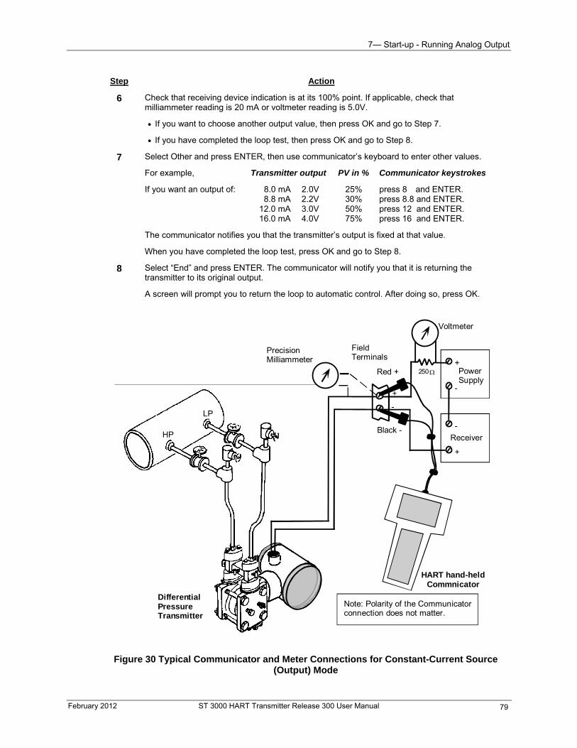
7— Start-up - Running Analog Output
February 2012 ST 3000 HART Transmitter Release 300 User Manual 79
Step Action
6 Check that receiving device indication is at its 100% point. If applicable, check that milliammeter reading is 20 mA or voltmeter reading is 5.0V.
If you want to choose another output value, then press OK and go to Step 7.
If you have completed the loop test, then press OK and go to Step 8.
7 Select Other and press ENTER, then use communicator’s keyboard to enter other values.
For example, Transmitter output PV in % Communicator keystrokes
If you want an output of: 8.0 mA 2.0V 25% press 8 and ENTER. 8.8 mA 2.2V 30% press 8.8 and ENTER. 12.0 mA 3.0V 50% press 12 and ENTER. 16.0 mA 4.0V 75% press 16 and ENTER.
The communicator notifies you that the transmitter’s output is fixed at that value.
When you have completed the loop test, press OK and go to Step 8.
8 Select “End” and press ENTER. The communicator will notify you that it is returning the transmitter to its original output.
A screen will prompt you to return the loop to automatic control. After doing so, press OK.
DifferentialPressureTransmitter
-
+
-
+
+
-
250
Voltmeter
PowerSupply
FieldTerminals
Receiver
Red +
Black -
PrecisionMilliammeter
HART hand-heldCommnicator
HP
LP
Note: Polarity of the Communicatorconnection does not matter.
Figure 30 Typical Communicator and Meter Connections for Constant-Current Source (Output) Mode
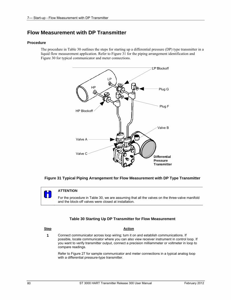
7— Start-up - Flow Measurement with DP Transmitter
Flow Measurement with DP Transmitter
Procedure
The procedure in Table 30 outlines the steps for starting up a differential pressure (DP) type transmitter in a liquid flow measurement application. Refer to Figure 31 for the piping arrangement identification and Figure 30 for typical communicator and meter connections.
HP
LP
LP Blockoff
Plug G
Plug F
Valve A
Valve B
Valve C
HP Blockoff
DifferentialPressureTransmitter
Figure 31 Typical Piping Arrangement for Flow Measurement with DP Type Transmitter
ATTENTION
For the procedure in Table 30, we are assuming that all the valves on the three-valve manifold and the block-off valves were closed at installation.
Table 30 Starting Up DP Transmitter for Flow Measurement
Step Action
1 Connect communicator across loop wiring; turn it on and establish communications. If possible, locate communicator where you can also view receiver instrument in control loop. If you want to verify transmitter output, connect a precision milliammeter or voltmeter in loop to compare readings.
Refer to Figure 27 for sample communicator and meter connections in a typical analog loop with a differential pressure-type transmitter.
ST 3000 HART Transmitter Release 300 User Manual February 2012 80
7— Start-up - Flow Measurement with DP Transmitter
February 2012 ST 3000 HART Transmitter Release 300 User Manual 81
Step Action
2 Open equalizer valve C.
Refer to Figure 28 for sample piping arrangement.
3 Open valves A and HP block-off to make differential pressure zero (0) by applying same pressure to both sides of meter body.
Allow system to stabilize at full static pressure—zero differential.
4 At the “Online” menu, read the applied input pressure (PV).
Also check that the PV analog output displays a corresponding zero input pressure.
5 Check that milliammeter reading is 4 mA (0%) output.
If communicator and milliammeter readings are…
exactly 4 mA, then go to Step 9.
not exactly 4 mA, then go to Step 6.
6 From “Online” menu, step through the following menu selections:
Device setup
Diag/Service
Calibration
Zero trim
7 Under “Zero trim” do the following when prompted:
Remove the loop from automatic control, then press OK.
Press OK when warned that this will affect sensor calibration.
Press OK when “Apply 0 input to sensor.” display appears.
You will receive a message telling you that the sensor input is stabilizing, then the sensor zero succeeded.
Return the loop to automatic control, then press OK.
8 Press HOME to return to “Online” menu. Repeat Steps 4 and 5.
9 Close equalizer valve C.
10 Open valve B and LP block-off valve to begin measuring process differential pressure.
11 Take communicator and milliammeter readings to check that output signal does correspond to applied input pressure.
If readings do not correspond, check that transmitter has been installed correctly. If applicable, blow down piping to be sure no foreign matter is entrapped in it.
Check communicator and milliammeter readings again. If readings are still not correct, verify transmitter’s configuration data and change its range setting, if necessary.
If device is not “Advanced Diagnostics for ST 3000 Release” skip to step 16.
12* On the next prompt – “Please enter Calibration Date”, enter the date in the format MM/DD/YYYY (ex: 05/27/2009), then press Enter
13* On the next prompt – “Please enter current Calibration Time in 24 Hr Clock format (Hour field)”, enter the hour portion of the calibration time in the 24 Hr format HH (ex: 13), then press Enter
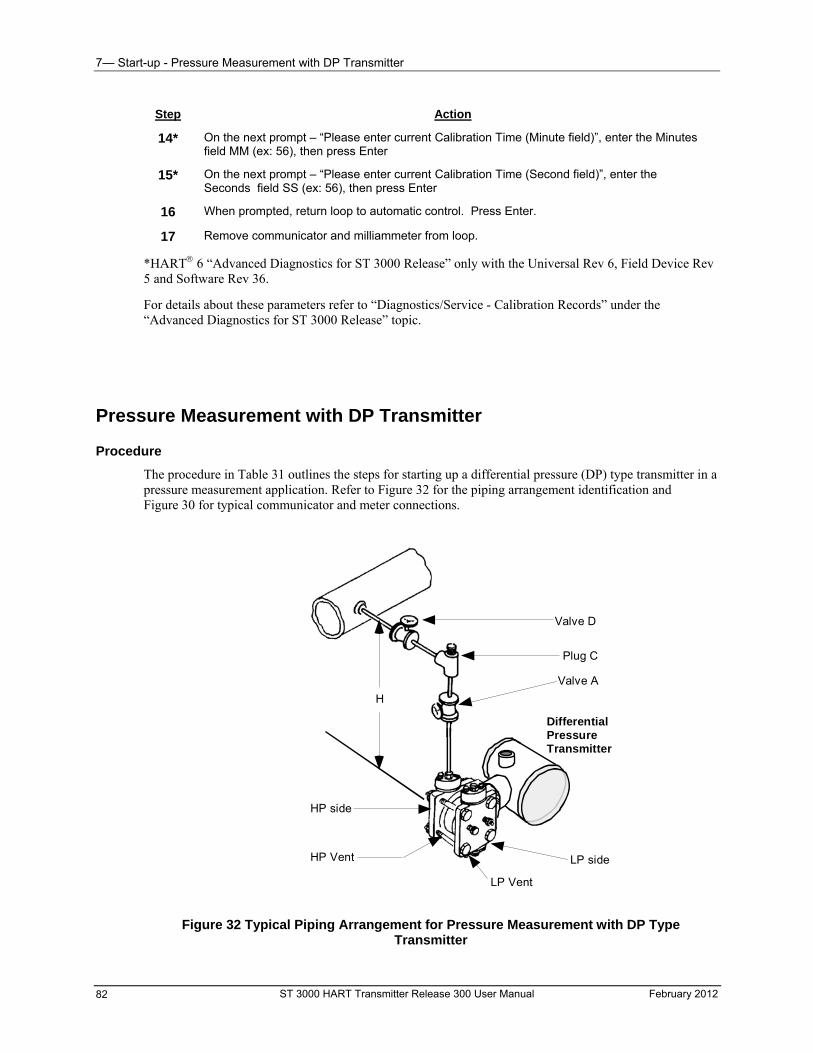
7— Start-up - Pressure Measurement with DP Transmitter
Step Action
14* On the next prompt – “Please enter current Calibration Time (Minute field)”, enter the Minutes field MM (ex: 56), then press Enter
15* On the next prompt – “Please enter current Calibration Time (Second field)”, enter the Seconds field SS (ex: 56), then press Enter
16 When prompted, return loop to automatic control. Press Enter.
17 Remove communicator and milliammeter from loop.
*HART 6 “Advanced Diagnostics for ST 3000 Release” only with the Universal Rev 6, Field Device Rev 5 and Software Rev 36.
For details about these parameters refer to “Diagnostics/Service - Calibration Records” under the “Advanced Diagnostics for ST 3000 Release” topic.
Pressure Measurement with DP Transmitter
Procedure
The procedure in Table 31 outlines the steps for starting up a differential pressure (DP) type transmitter in a pressure measurement application. Refer to Figure 32 for the piping arrangement identification and Figure 30 for typical communicator and meter connections.
Valve D
Valve A
Plug C
LP Vent
HP Vent
HP side
DifferentialPressureTransmitter
LP side
H
Figure 32 Typical Piping Arrangement for Pressure Measurement with DP Type Transmitter
ST 3000 HART Transmitter Release 300 User Manual February 2012 82
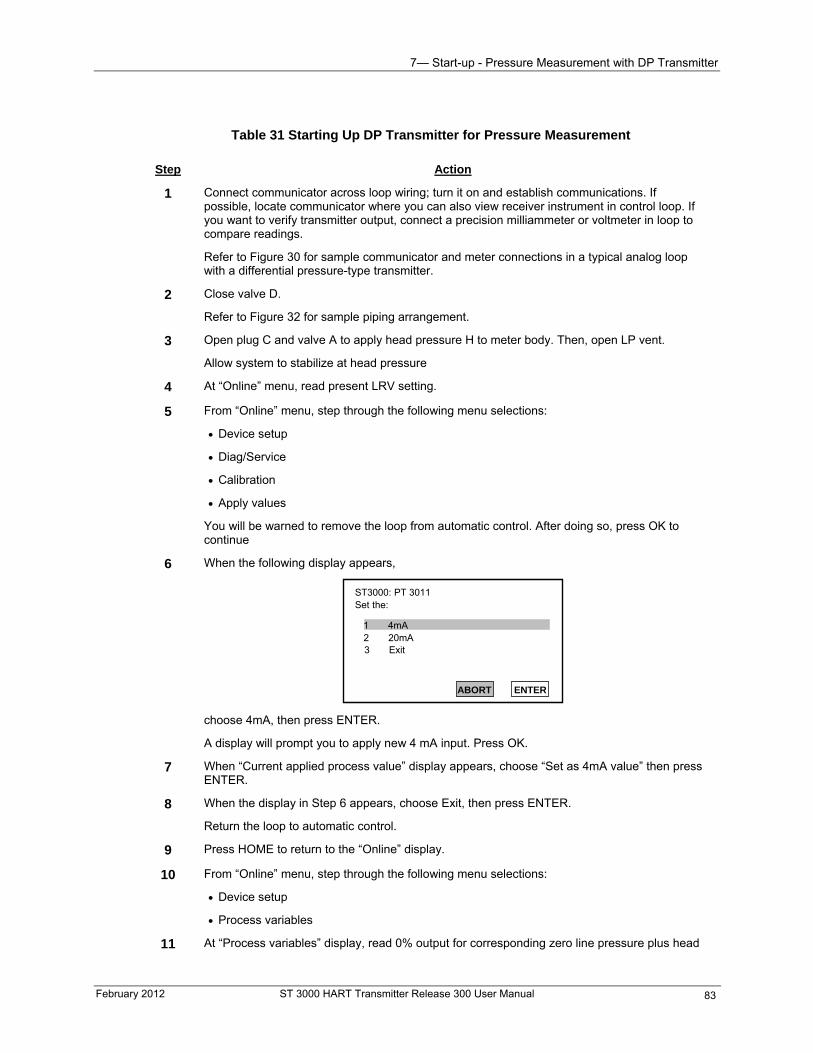
7— Start-up - Pressure Measurement with DP Transmitter
February 2012 ST 3000 HART Transmitter Release 300 User Manual 83
Table 31 Starting Up DP Transmitter for Pressure Measurement
Step Action
1 Connect communicator across loop wiring; turn it on and establish communications. If possible, locate communicator where you can also view receiver instrument in control loop. If you want to verify transmitter output, connect a precision milliammeter or voltmeter in loop to compare readings.
Refer to Figure 30 for sample communicator and meter connections in a typical analog loop with a differential pressure-type transmitter.
2 Close valve D.
Refer to Figure 32 for sample piping arrangement.
3 Open plug C and valve A to apply head pressure H to meter body. Then, open LP vent.
Allow system to stabilize at head pressure
4 At “Online” menu, read present LRV setting.
5 From “Online” menu, step through the following menu selections:
Device setup
Diag/Service
Calibration
Apply values
You will be warned to remove the loop from automatic control. After doing so, press OK to continue
6 When the following display appears,
ST3000: PT 3011 Set the:
1 4mA2 20mA
ABORT ENTER
3 Exit
choose 4mA, then press ENTER.
A display will prompt you to apply new 4 mA input. Press OK.
7 When “Current applied process value” display appears, choose “Set as 4mA value” then press ENTER.
8 When the display in Step 6 appears, choose Exit, then press ENTER.
Return the loop to automatic control.
9 Press HOME to return to the “Online” display.
10 From “Online” menu, step through the following menu selections:
Device setup
Process variables
11 At “Process variables” display, read 0% output for corresponding zero line pressure plus head
7— Start-up - Pressure Measurement with DP Transmitter
Step Action
pressure H. Check that milliammeter reading is 4 mA (0%) output.
12 Close plug C
13 Open valve D to begin measuring process line pressure.
14 Take communicator and milliammeter readings to check that output signal does correspond to applied line pressure.
If readings do not correspond, check that transmitter has been installed correctly. If applicable, blow down piping to be sure no foreign matter is entrapped in it.
Check communicator and milliammeter readings again. If readings are still not correct, verify transmitter’s configuration data and change its range setting if needed.
15 Remove communicator and milliammeter from loop.
ST 3000 HART Transmitter Release 300 User Manual February 2012 84
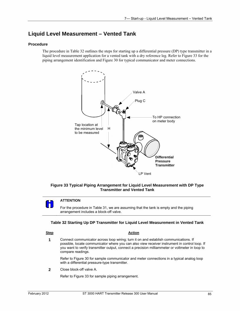
7— Start-up - Liquid Level Measurement – Vented Tank
Liquid Level Measurement – Vented Tank
Procedure
The procedure in Table 32 outlines the steps for starting up a differential pressure (DP) type transmitter in a liquid level measurement application for a vented tank with a dry reference leg. Refer to Figure 33 for the piping arrangement identification and Figure 30 for typical communicator and meter connections.
Valve A
Plug C
LP Vent
Tap location atthe minimum levelto be measured
To HP connectionon meter body
DifferentialPressureTransmitter
H
Figure 33 Typical Piping Arrangement for Liquid Level Measurement with DP Type Transmitter and Vented Tank
ATTENTION
For the procedure in Table 31, we are assuming that the tank is empty and the piping arrangement includes a block-off valve.
Table 32 Starting Up DP Transmitter for Liquid Level Measurement in Vented Tank
Step Action
1 Connect communicator across loop wiring; turn it on and establish communications. If possible, locate communicator where you can also view receiver instrument in control loop. If you want to verify transmitter output, connect a precision milliammeter or voltmeter in loop to compare readings.
Refer to Figure 30 for sample communicator and meter connections in a typical analog loop with a differential pressure-type transmitter.
2 Close block-off valve A.
Refer to Figure 33 for sample piping arrangement.
February 2012 ST 3000 HART Transmitter Release 300 User Manual 85
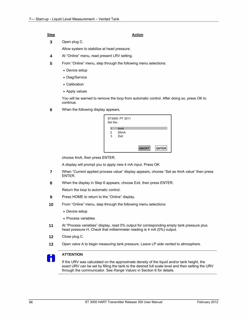
7— Start-up - Liquid Level Measurement – Vented Tank
ST 3000 HART Transmitter Release 300 User Manual February 2012 86
Step Action
3 Open plug C.
Allow system to stabilize at head pressure.
4 At “Online” menu, read present LRV setting.
5 From “Online” menu, step through the following menu selections:
Device setup
Diag/Service
Calibration
Apply values
You will be warned to remove the loop from automatic control. After doing so, press OK to continue.
6 When the following display appears,
ST3000: PT 3011 Set the:
1 4mA2 20mA
ABORT ENTER
3 Exit
choose 4mA, then press ENTER.
A display will prompt you to apply new 4 mA input. Press OK.
7 When “Current applied process value” display appears, choose “Set as 4mA value” then press ENTER.
8 When the display in Step 6 appears, choose Exit, then press ENTER.
Return the loop to automatic control.
9 Press HOME to return to the “Online” display.
10 From “Online” menu, step through the following menu selections:
Device setup
Process variables
11 At “Process variables” display, read 0% output for corresponding empty tank pressure plus head pressure H. Check that milliammeter reading is 4 mA (0%) output.
12 Close plug C.
13 Open valve A to begin measuring tank pressure. Leave LP side vented to atmosphere.
ATTENTION
If the URV was calculated on the approximate density of the liquid and/or tank height, the exact URV can be set by filling the tank to the desired full scale level and then setting the URV through the communicator. See Range Values in Section 6 for details.
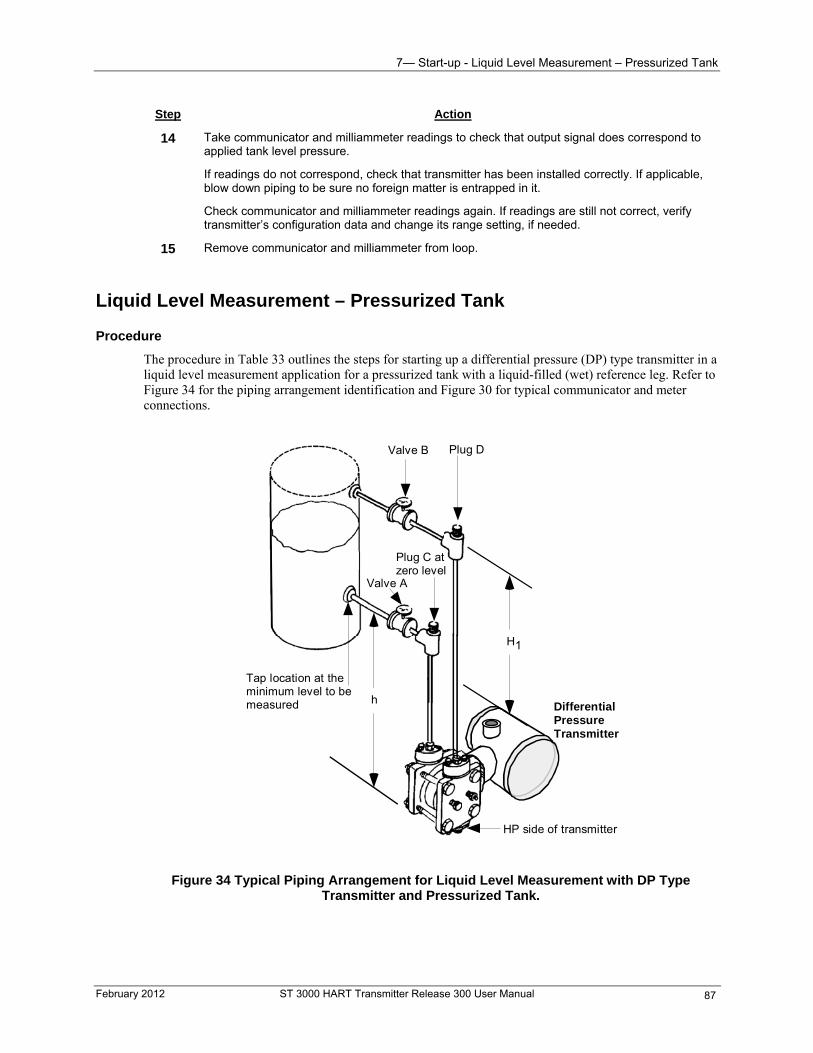
7— Start-up - Liquid Level Measurement – Pressurized Tank
Step Action
14 Take communicator and milliammeter readings to check that output signal does correspond to applied tank level pressure.
If readings do not correspond, check that transmitter has been installed correctly. If applicable, blow down piping to be sure no foreign matter is entrapped in it.
Check communicator and milliammeter readings again. If readings are still not correct, verify transmitter’s configuration data and change its range setting, if needed.
15 Remove communicator and milliammeter from loop.
Liquid Level Measurement – Pressurized Tank
Procedure
The procedure in Table 33 outlines the steps for starting up a differential pressure (DP) type transmitter in a liquid level measurement application for a pressurized tank with a liquid-filled (wet) reference leg. Refer to Figure 34 for the piping arrangement identification and Figure 30 for typical communicator and meter connections.
Valve A
Plug C atzero level
Tap location at theminimum level to bemeasured
HP side of transmitter
DifferentialPressureTransmitter
h
H1
Valve B Plug D
Figure 34 Typical Piping Arrangement for Liquid Level Measurement with DP Type Transmitter and Pressurized Tank.
February 2012 ST 3000 HART Transmitter Release 300 User Manual 87
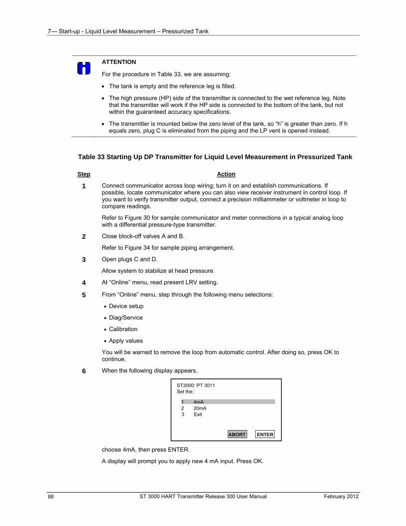
7— Start-up - Liquid Level Measurement – Pressurized Tank
ST 3000 HART Transmitter Release 300 User Manual February 2012 88
ATTENTION
For the procedure in Table 33, we are assuming:
The tank is empty and the reference leg is filled.
The high pressure (HP) side of the transmitter is connected to the wet reference leg. Note that the transmitter will work if the HP side is connected to the bottom of the tank, but not within the guaranteed accuracy specifications.
The transmitter is mounted below the zero level of the tank, so “h” is greater than zero. If h equals zero, plug C is eliminated from the piping and the LP vent is opened instead.
Table 33 Starting Up DP Transmitter for Liquid Level Measurement in Pressurized Tank
Step Action
1 Connect communicator across loop wiring; turn it on and establish communications. If possible, locate communicator where you can also view receiver instrument in control loop. If you want to verify transmitter output, connect a precision milliammeter or voltmeter in loop to compare readings.
Refer to Figure 30 for sample communicator and meter connections in a typical analog loop with a differential pressure-type transmitter.
2 Close block-off valves A and B.
Refer to Figure 34 for sample piping arrangement.
3 Open plugs C and D.
Allow system to stabilize at head pressure.
4 At “Online” menu, read present LRV setting.
5 From “Online” menu, step through the following menu selections:
Device setup
Diag/Service
Calibration
Apply values
You will be warned to remove the loop from automatic control. After doing so, press OK to continue.
6 When the following display appears,
ST3000: PT 3011 Set the:
1 4mA2 20mA
ABORT ENTER
3 Exit
choose 4mA, then press ENTER.
A display will prompt you to apply new 4 mA input. Press OK.
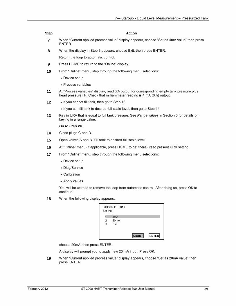
7— Start-up - Liquid Level Measurement – Pressurized Tank
February 2012 ST 3000 HART Transmitter Release 300 User Manual 89
Step Action
7 When “Current applied process value” display appears, choose “Set as 4mA value” then press ENTER.
8 When the display in Step 6 appears, choose Exit, then press ENTER.
Return the loop to automatic control.
9 Press HOME to return to the “Online” display.
10 From “Online” menu, step through the following menu selections:
Device setup
Process variables
11 At “Process variables” display, read 0% output for corresponding empty tank pressure plus head pressure H1. Check that milliammeter reading is 4 mA (0%) output.
12 If you cannot fill tank, then go to Step 13
If you can fill tank to desired full-scale level, then go to Step 14
13 Key in URV that is equal to full tank pressure. See Range values in Section 6 for details on keying in a range value.
Go to Step 24
14 Close plugs C and D.
15 Open valves A and B. Fill tank to desired full scale level.
16 At “Online” menu (if applicable, press HOME to get there), read present URV setting.
17 From “Online” menu, step through the following menu selections:
Device setup
Diag/Service
Calibration
Apply values
You will be warned to remove the loop from automatic control. After doing so, press OK to continue.
18 When the following display appears,
ST3000: PT 3011 Set the:
1 4mA2 20mA
ABORT ENTER
3 Exit
choose 20mA, then press ENTER.
A display will prompt you to apply new 20 mA input. Press OK.
19 When “Current applied process value” display appears, choose “Set as 20mA value” then press ENTER.
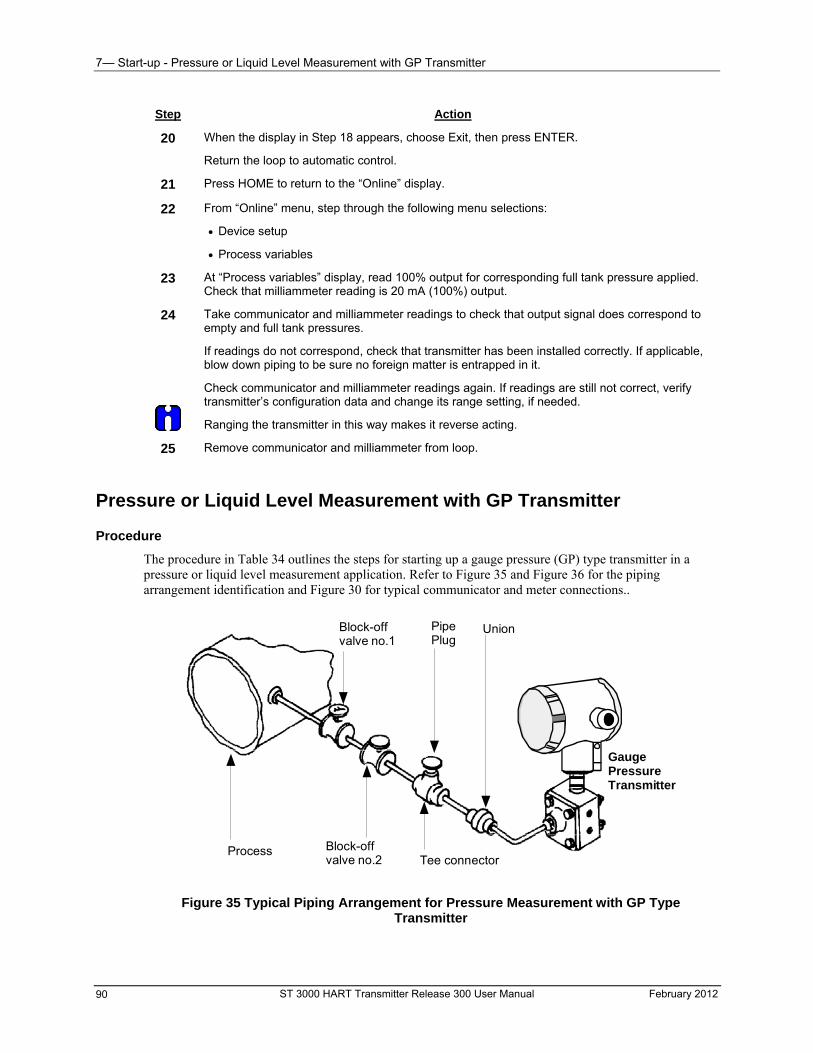
7— Start-up - Pressure or Liquid Level Measurement with GP Transmitter
ST 3000 HART Transmitter Release 300 User Manual February 2012 90
Step Action
20 When the display in Step 18 appears, choose Exit, then press ENTER.
Return the loop to automatic control.
21 Press HOME to return to the “Online” display.
22 From “Online” menu, step through the following menu selections:
Device setup
Process variables
23 At “Process variables” display, read 100% output for corresponding full tank pressure applied. Check that milliammeter reading is 20 mA (100%) output.
24
Take communicator and milliammeter readings to check that output signal does correspond to empty and full tank pressures.
If readings do not correspond, check that transmitter has been installed correctly. If applicable, blow down piping to be sure no foreign matter is entrapped in it.
Check communicator and milliammeter readings again. If readings are still not correct, verify transmitter’s configuration data and change its range setting, if needed.
Ranging the transmitter in this way makes it reverse acting.
25 Remove communicator and milliammeter from loop.
Pressure or Liquid Level Measurement with GP Transmitter
Procedure
The procedure in Table 34 outlines the steps for starting up a gauge pressure (GP) type transmitter in a pressure or liquid level measurement application. Refer to Figure 35 and Figure 36 for the piping arrangement identification and Figure 30 for typical communicator and meter connections..
Block-offvalve no.2
GaugePressureTransmitter
UnionBlock-offvalve no.1
PipePlug
ProcessTee connector
Figure 35 Typical Piping Arrangement for Pressure Measurement with GP Type Transmitter
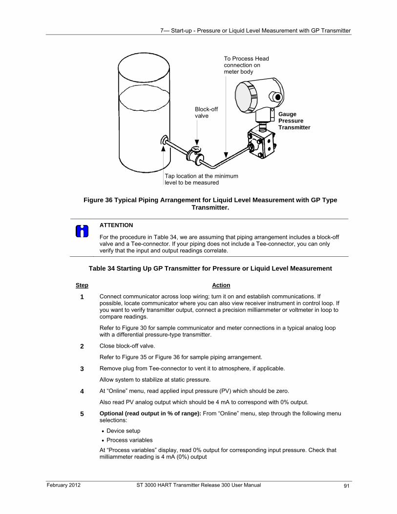
7— Start-up - Pressure or Liquid Level Measurement with GP Transmitter
February 2012 ST 3000 HART Transmitter Release 300 User Manual 91
Tap location at the minimumlevel to be measured
GaugePressureTransmitter
Block-offvalve
To Process Headconnection onmeter body
Figure 36 Typical Piping Arrangement for Liquid Level Measurement with GP Type Transmitter.
ATTENTION
For the procedure in Table 34, we are assuming that piping arrangement includes a block-off valve and a Tee-connector. If your piping does not include a Tee-connector, you can only verify that the input and output readings correlate.
Table 34 Starting Up GP Transmitter for Pressure or Liquid Level Measurement
Step Action
1 Connect communicator across loop wiring; turn it on and establish communications. If possible, locate communicator where you can also view receiver instrument in control loop. If you want to verify transmitter output, connect a precision milliammeter or voltmeter in loop to compare readings.
Refer to Figure 30 for sample communicator and meter connections in a typical analog loop with a differential pressure-type transmitter.
2 Close block-off valve.
Refer to Figure 35 or Figure 36 for sample piping arrangement.
3 Remove plug from Tee-connector to vent it to atmosphere, if applicable.
Allow system to stabilize at static pressure.
4 At “Online” menu, read applied input pressure (PV) which should be zero.
Also read PV analog output which should be 4 mA to correspond with 0% output.
5 Optional (read output in % of range): From “Online” menu, step through the following menu selections:
Device setup
Process variables
At “Process variables” display, read 0% output for corresponding input pressure. Check that milliammeter reading is 4 mA (0%) output
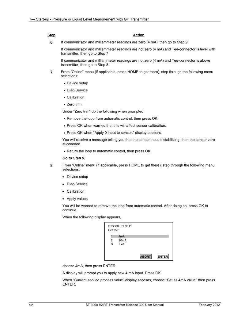
7— Start-up - Pressure or Liquid Level Measurement with GP Transmitter
ST 3000 HART Transmitter Release 300 User Manual February 2012 92
Step Action
6 If communicator and milliammeter readings are zero (4 mA), then go to Step 9.
If communicator and milliammeter readings are not zero (4 mA) and Tee-connector is level with transmitter, then go to Step 7
If communicator and milliammeter readings are not zero (4 mA) and Tee-connector is above transmitter, then go to Step 8
7 From “Online” menu (if applicable, press HOME to get there), step through the following menu selections:
Device setup
Diag/Service
Calibration
Zero trim
Under “Zero trim” do the following when prompted:
Remove the loop from automatic control, then press OK.
Press OK when warned that this will affect sensor calibration.
Press OK when “Apply 0 input to sensor.” display appears.
You will receive a message telling you that the sensor input is stabilizing, then the sensor zero succeeded.
Return the loop to automatic control, then press OK.
Go to Step 9.
8
From “Online” menu (if applicable, press HOME to get there), step through the following menu selections:
Device setup
Diag/Service
Calibration
Apply values
You will be warned to remove the loop from automatic control. After doing so, press OK to continue.
When the following display appears,
ST3000: PT 3011 Set the:
1 4mA2 20mA
ABORT ENTER
3 Exit
choose 4mA, then press ENTER.
A display will prompt you to apply new 4 mA input. Press OK.
When “Current applied process value” display appears, choose “Set as 4mA value” then press ENTER.
7— Start-up - Pressure Measurement with AP
Step Action
8, cont’d
When the display above appears, choose Exit, then press ENTER.
Return the loop to automatic control.
9 Close Tee-connector and slowly open block-off valve to apply process pressure to transmitter.
10 Take communicator and milliammeter readings to check that output signal does correspond to zero and full-scale pressures.
If readings do not correspond, check that transmitter has been installed correctly. If applicable, blow down piping to be sure no foreign matter is entrapped in it.
Check communicator and milliammeter readings again. If readings are still not correct, verify transmitter’s configuration data and change its range setting if needed.
If device is not “Advanced Diagnostics for ST 3000 Release” skip to step 15.
11* On the next prompt – “Please enter Calibration Date”, enter the date in the format MM/DD/YYYY (ex: 05/27/2009), then press Enter
12* On the next prompt – “Please enter current Calibration Time in 24 Hr Clock format (Hour field)”, enter the hour portion of the calibration time in the 24 Hr format HH (ex: 13), then press Enter
13* On the next prompt – “Please enter current Calibration Time (Minute field)”, enter the Minutes field MM (ex: 56), then press Enter
14* On the next prompt – “Please enter current Calibration Time (Second field)”, enter the Seconds field SS (ex: 56), then press Enter
15 When prompted, return loop to automatic control. Press Enter.
16 Remove communicator and milliammeter from loop.
Pressure Measurement with AP
Procedure
The procedure in Table 35 outlines the steps for starting up an absolute pressure (AP). type transmitter in a pressure measurement application. Refer to Figure 37 for the piping arrangement identification and Figure 30 for typical communicator and meter connections.
February 2012 ST 3000 HART Transmitter Release 300 User Manual 93
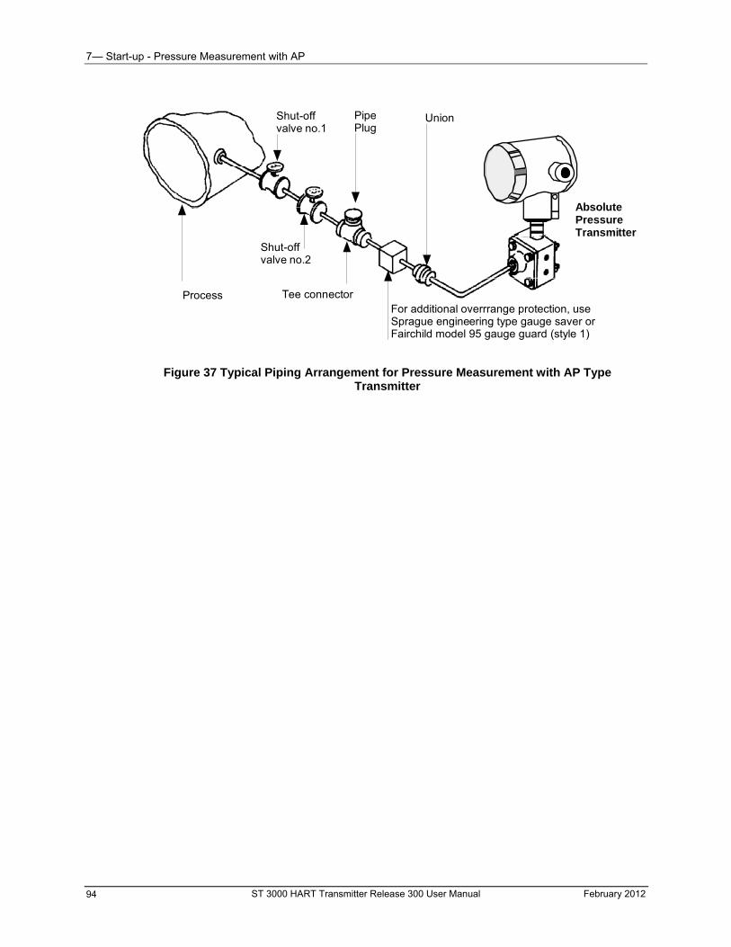
7— Start-up - Pressure Measurement with AP
Shut-offvalve no.2
AbsolutePressureTransmitter
UnionShut-offvalve no.1
PipePlug
Process Tee connectorFor additional overrrange protection, useSprague engineering type gauge saver orFairchild model 95 gauge guard (style 1)
Figure 37 Typical Piping Arrangement for Pressure Measurement with AP Type Transmitter
ST 3000 HART Transmitter Release 300 User Manual February 2012 94
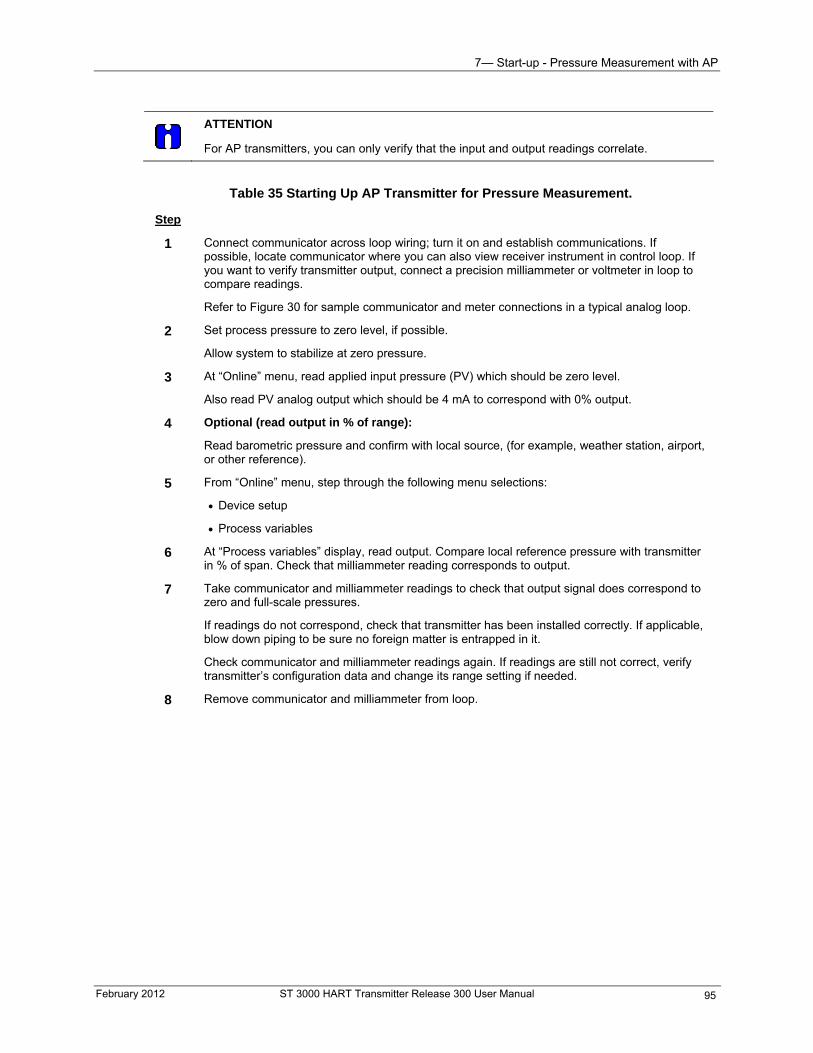
7— Start-up - Pressure Measurement with AP
February 2012 ST 3000 HART Transmitter Release 300 User Manual 95
ATTENTION
For AP transmitters, you can only verify that the input and output readings correlate.
Table 35 Starting Up AP Transmitter for Pressure Measurement.
Step
1 Connect communicator across loop wiring; turn it on and establish communications. If possible, locate communicator where you can also view receiver instrument in control loop. If you want to verify transmitter output, connect a precision milliammeter or voltmeter in loop to compare readings.
Refer to Figure 30 for sample communicator and meter connections in a typical analog loop.
2 Set process pressure to zero level, if possible.
Allow system to stabilize at zero pressure.
3 At “Online” menu, read applied input pressure (PV) which should be zero level.
Also read PV analog output which should be 4 mA to correspond with 0% output.
4 Optional (read output in % of range):
Read barometric pressure and confirm with local source, (for example, weather station, airport, or other reference).
5 From “Online” menu, step through the following menu selections:
Device setup
Process variables
6 At “Process variables” display, read output. Compare local reference pressure with transmitter in % of span. Check that milliammeter reading corresponds to output.
7 Take communicator and milliammeter readings to check that output signal does correspond to zero and full-scale pressures.
If readings do not correspond, check that transmitter has been installed correctly. If applicable, blow down piping to be sure no foreign matter is entrapped in it.
Check communicator and milliammeter readings again. If readings are still not correct, verify transmitter’s configuration data and change its range setting if needed.
8 Remove communicator and milliammeter from loop.
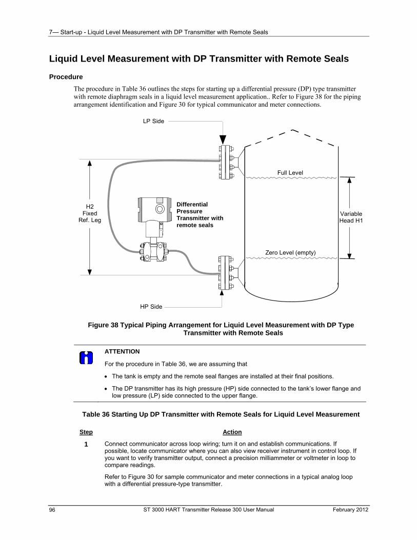
7— Start-up - Liquid Level Measurement with DP Transmitter with Remote Seals
Liquid Level Measurement with DP Transmitter with Remote Seals
Procedure
The procedure in Table 36 outlines the steps for starting up a differential pressure (DP) type transmitter with remote diaphragm seals in a liquid level measurement application.. Refer to Figure 38 for the piping arrangement identification and Figure 30 for typical communicator and meter connections.
DifferentialPressureTransmitter withremote seals
LP Side
HP Side
H2Fixed
Ref. Leg
Zero Level (empty)
Full Level
VariableHead H1
Figure 38 Typical Piping Arrangement for Liquid Level Measurement with DP Type Transmitter with Remote Seals
ATTENTION
For the procedure in Table 36, we are assuming that
The tank is empty and the remote seal flanges are installed at their final positions.
The DP transmitter has its high pressure (HP) side connected to the tank’s lower flange and low pressure (LP) side connected to the upper flange.
Table 36 Starting Up DP Transmitter with Remote Seals for Liquid Level Measurement
Step Action
1 Connect communicator across loop wiring; turn it on and establish communications. If possible, locate communicator where you can also view receiver instrument in control loop. If you want to verify transmitter output, connect a precision milliammeter or voltmeter in loop to compare readings.
Refer to Figure 30 for sample communicator and meter connections in a typical analog loop with a differential pressure-type transmitter.
ST 3000 HART Transmitter Release 300 User Manual February 2012 96
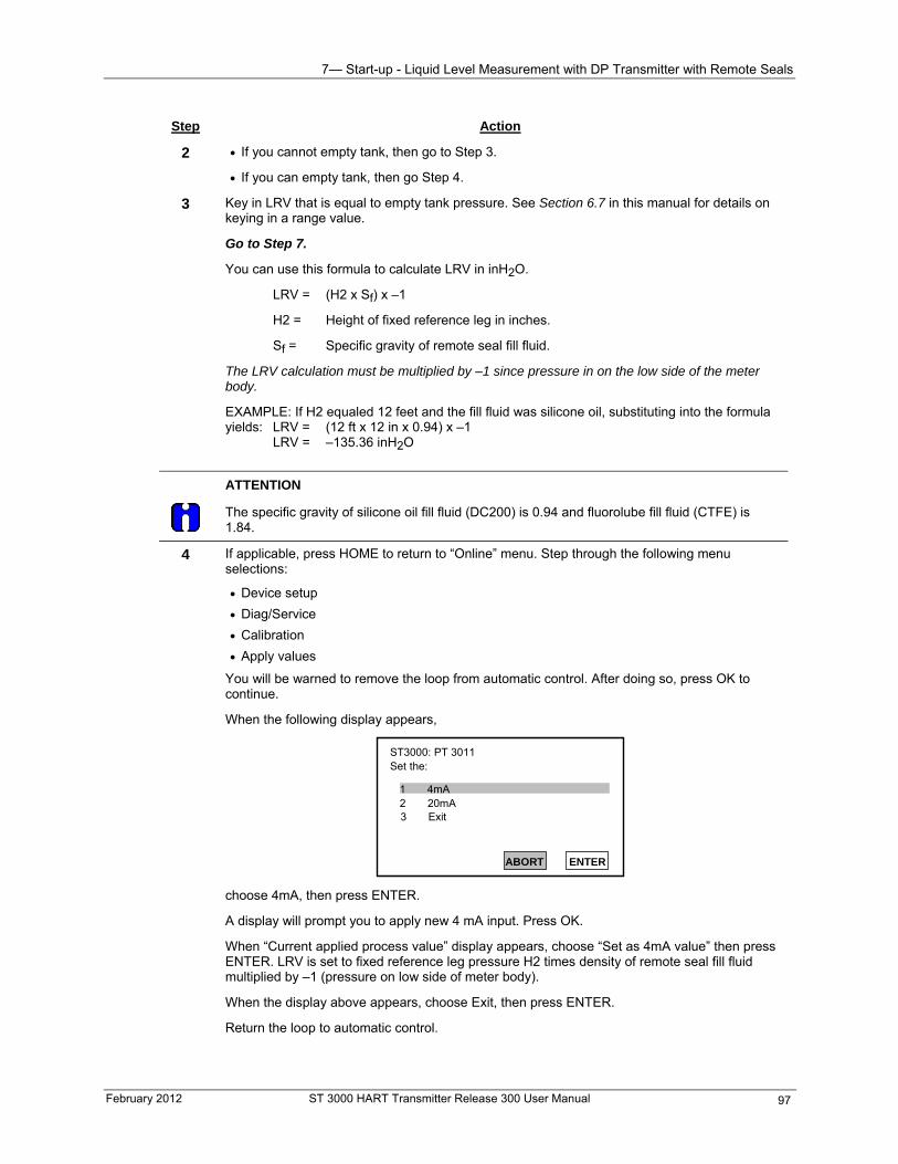
7— Start-up - Liquid Level Measurement with DP Transmitter with Remote Seals
February 2012 ST 3000 HART Transmitter Release 300 User Manual 97
Step Action
2
If you cannot empty tank, then go to Step 3.
If you can empty tank, then go Step 4.
3 Key in LRV that is equal to empty tank pressure. See Section 6.7 in this manual for details on keying in a range value.
Go to Step 7.
You can use this formula to calculate LRV in inH2O.
LRV = (H2 x Sf) x –1
H2 = Height of fixed reference leg in inches.
Sf = Specific gravity of remote seal fill fluid.
The LRV calculation must be multiplied by –1 since pressure in on the low side of the meter body.
EXAMPLE: If H2 equaled 12 feet and the fill fluid was silicone oil, substituting into the formula yields: LRV = (12 ft x 12 in x 0.94) x –1 LRV = –135.36 inH2O
ATTENTION
The specific gravity of silicone oil fill fluid (DC200) is 0.94 and fluorolube fill fluid (CTFE) is 1.84.
4 If applicable, press HOME to return to “Online” menu. Step through the following menu selections:
Device setup
Diag/Service
Calibration
Apply values
You will be warned to remove the loop from automatic control. After doing so, press OK to continue.
When the following display appears,
ST3000: PT 3011 Set the:
1 4mA2 20mA
ABORT ENTER
3 Exit
choose 4mA, then press ENTER.
A display will prompt you to apply new 4 mA input. Press OK.
When “Current applied process value” display appears, choose “Set as 4mA value” then press ENTER. LRV is set to fixed reference leg pressure H2 times density of remote seal fill fluid multiplied by –1 (pressure on low side of meter body).
When the display above appears, choose Exit, then press ENTER.
Return the loop to automatic control.
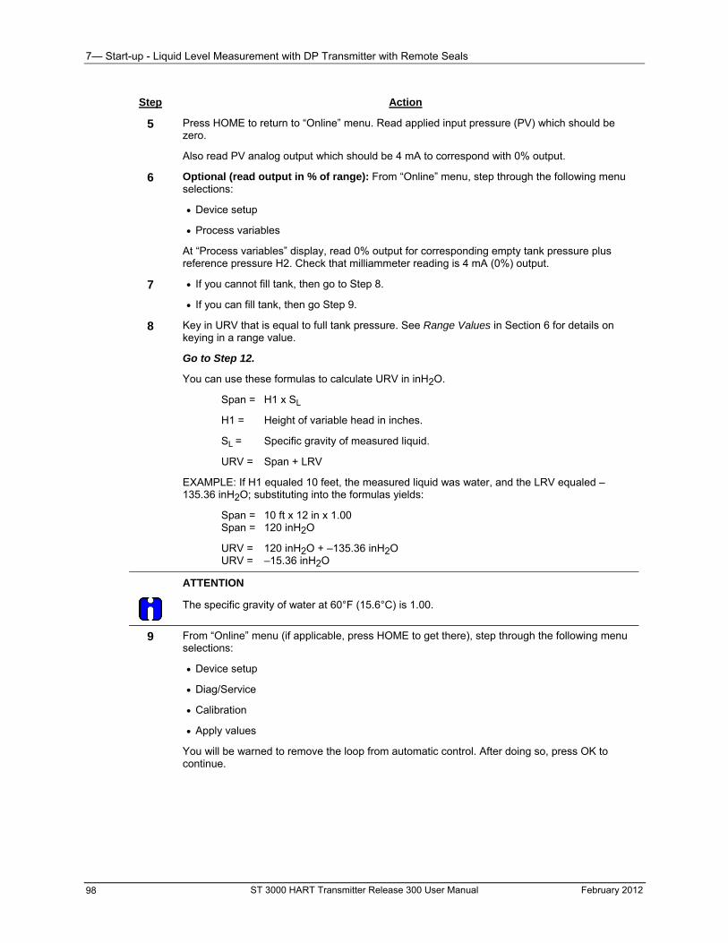
7— Start-up - Liquid Level Measurement with DP Transmitter with Remote Seals
Step Action
5 Press HOME to return to “Online” menu. Read applied input pressure (PV) which should be zero.
Also read PV analog output which should be 4 mA to correspond with 0% output.
6 Optional (read output in % of range): From “Online” menu, step through the following menu selections:
Device setup
Process variables
At “Process variables” display, read 0% output for corresponding empty tank pressure plus reference pressure H2. Check that milliammeter reading is 4 mA (0%) output.
7 If you cannot fill tank, then go to Step 8.
If you can fill tank, then go Step 9.
8 Key in URV that is equal to full tank pressure. See Range Values in Section 6 for details on keying in a range value.
Go to Step 12.
You can use these formulas to calculate URV in inH2O.
Span = H1 x SL
H1 = Height of variable head in inches.
SL = Specific gravity of measured liquid.
URV = Span + LRV
EXAMPLE: If H1 equaled 10 feet, the measured liquid was water, and the LRV equaled –135.36 inH2O; substituting into the formulas yields:
Span = 10 ft x 12 in x 1.00 Span = 120 inH2O
URV = 120 inH2O + –135.36 inH2O URV = –15.36 inH2O
ATTENTION
The specific gravity of water at 60°F (15.6°C) is 1.00.
9
From “Online” menu (if applicable, press HOME to get there), step through the following menu selections:
Device setup
Diag/Service
Calibration
Apply values
You will be warned to remove the loop from automatic control. After doing so, press OK to continue.
ST 3000 HART Transmitter Release 300 User Manual February 2012 98
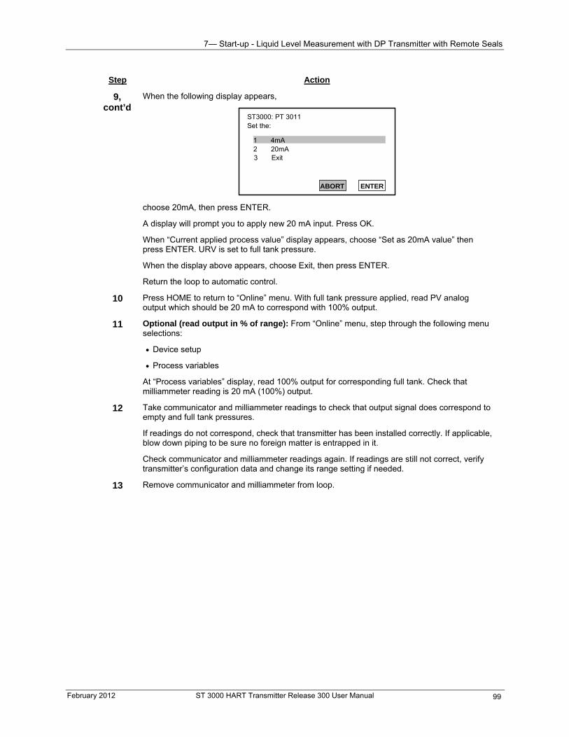
7— Start-up - Liquid Level Measurement with DP Transmitter with Remote Seals
February 2012 ST 3000 HART Transmitter Release 300 User Manual 99
Step Action
9, cont’d
When the following display appears,
ST3000: PT 3011 Set the:
1 4mA2 20mA
ABORT ENTER
3 Exit
choose 20mA, then press ENTER.
w 20 mA input. Press OK.
“Set as 20mA value” then
ER.
10 With full tank pressure applied, read PV analog
11 p through the following menu
tup
les
At display, read 100% output for corresponding full tank. Check that
12 to check that output signal does correspond to
heck that transmitter has been installed correctly. If applicable,
s are still not correct, verify
13
A display will prompt you to apply ne
When “Current applied process value” display appears, choose press ENTER. URV is set to full tank pressure.
When the display above appears, choose Exit, then press ENT
Return the loop to automatic control.
Press HOME to return to “Online” menu.output which should be 20 mA to correspond with 100% output.
Optional (read output in % of range): From “Online” menu, steselections:
Device se
Process variab
“Process variables”milliammeter reading is 20 mA (100%) output.
Take communicator and milliammeter readingsempty and full tank pressures.
If readings do not correspond, cblow down piping to be sure no foreign matter is entrapped in it.
Check communicator and milliammeter readings again. If readingtransmitter’s configuration data and change its range setting if needed.
Remove communicator and milliammeter from loop.

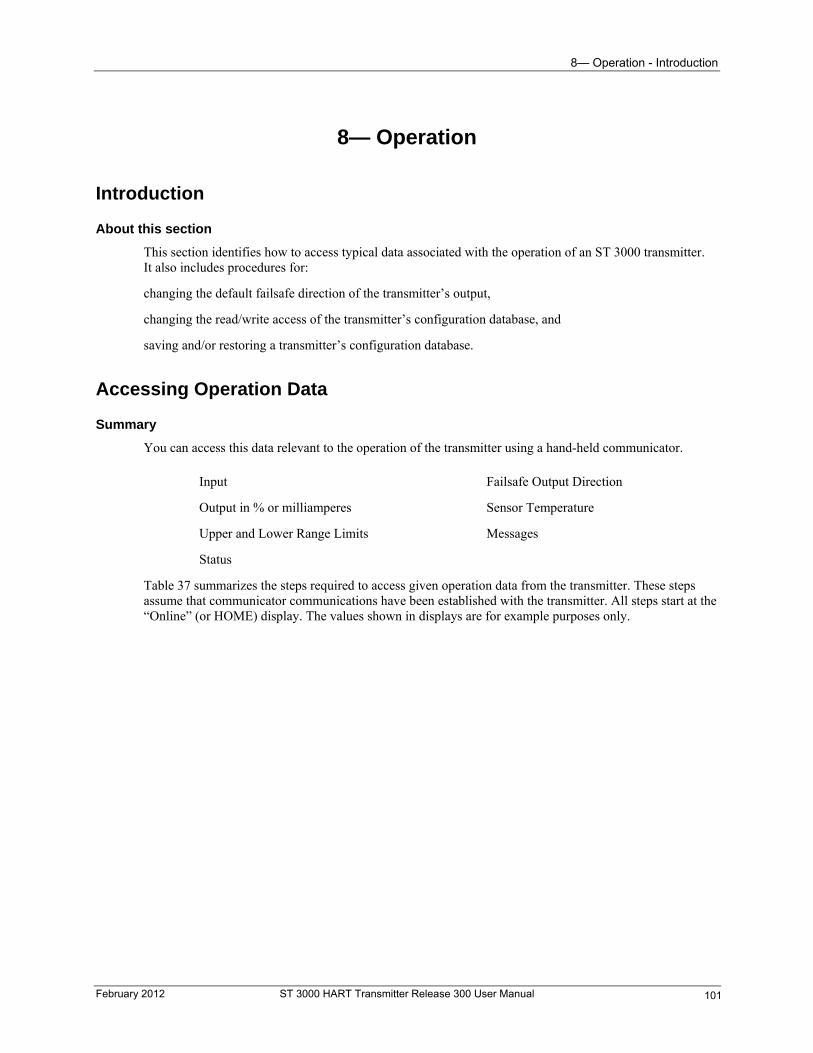
8— Operation - Introduction
8— Operation
Introduction
About this section
This section identifies how to access typical data associated with the operation of an ST 3000 transmitter. It also includes procedures for:
changing the default failsafe direction of the transmitter’s output,
changing the read/write access of the transmitter’s configuration database, and
saving and/or restoring a transmitter’s configuration database.
Accessing Operation Data
Summary
You can access this data relevant to the operation of the transmitter using a hand-held communicator.
Input
Output in % or milliamperes
Upper and Lower Range Limits
Status
Failsafe Output Direction
Sensor Temperature
Messages
Table 37 summarizes the steps required to access given operation data from the transmitter. These steps assume that communicator communications have been established with the transmitter. All steps start at the “Online” (or HOME) display. The values shown in displays are for example purposes only.
February 2012 ST 3000 HART Transmitter Release 300 User Manual 101
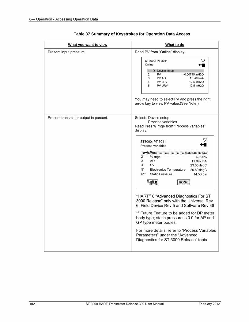
8— Operation - Accessing Operation Data
ST 3000 HART Transmitter Release 300 User Manual February 2012 102
Table 37 Summary of Keystrokes for Operation Data Access
What you want to view What to do
Present input pressure. Read PV from “Online” display.
ST3000: PT 3011 Online
3 4 5
PV AO PV LRV PV URV
–0.00745 inH2O 11.989 mA
–12.5 inH2O 12.5 inH2O
1 2
Device setup PV
You may need to select PV and press the right arrow key to view PV value.(See Note.)
Present transmitter output in percent. Select: Device setup Process variables Read Pres % rnge from “Process variables” display.
*HART 6 “Advanced Diagnostics For ST 3000 Release” only with the Universal Rev 6, Field Device Rev 5 and Software Rev 36
** Future Feature to be added for DP meter body type; static pressure is 0.0 for AP and GP type meter bodies.
For more details, refer to “Process Variables Parameters” under the “Advanced Diagnostics for ST 3000 Release” topic.
ST3000: PT 3011 Process variables
3 4
5*
6**
AO SV
Electronics Temperature
Static Pressure
11.992mA 23.50
20.69
degC
degC
1 2
Pres % rnge
–0.00745 inH2O 49.95%
HELP HOME
14.50 psi
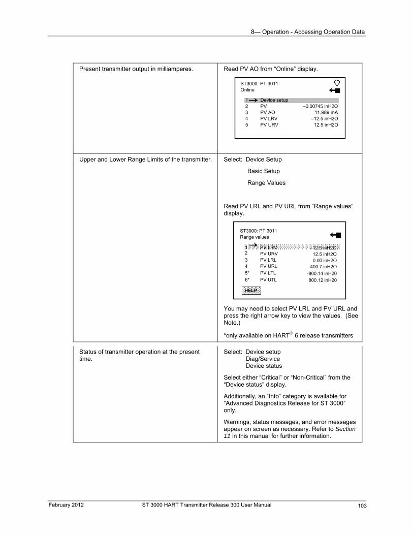
8— Operation - Accessing Operation Data
Present transmitter output in milliamperes. Read PV AO from “Online” display.
ST3000: PT 3011 Online
3 4 5
PV AO PV LRV PV URV
–0.00745 inH2O 11.989 mA
–12.5 inH2O 12.5 inH2O
1 2
Device setup PV
Upper and Lower Range Limits of the transmitter.
Select: Device Setup
Basic Setup
Range Values
Read PV LRL and PV URL from “Range values” display.
You may need to select PV LRL and PV URL and press the right arrow key to view the values. (See Note.)
*only available on HART 6 release transmitters Status of transmitter operation at the present time.
Select: Device setup Diag/Service Device status
Select either “Critical” or “Non-Critical” from the “Device status” display.
Additionally, an “Info” category is available for “Advanced Diagnostics Release for ST 3000” only.
Warnings, status messages, and error messages appear on screen as necessary. Refer to Section 11 in this manual for further information.
HELP
ST3000: PT 3011 Range values
3 4
5*
6*
PV LRL PV URL
PV LTL
PV UTL
0.00 inH2O
–12.5 inH2O 12.5 inH2O
PV LRV PV URV
1 2
400.7 inH2O
-800.14 inH20
800.12 inH20
February 2012 ST 3000 HART Transmitter Release 300 User Manual 103
8— Operation - Accessing Operation Data
Present failsafe output direction, which depends on the position of the internal failure mode alarm jumper.
Select: Device setup Detailed setup Output condition Analog output Read AO Alrm typ from “Analog output” display.
ST3000: PT 3011 Analog output
3 4
Loop test D/A trim
1 2
AO AO Alrm typ
11.990 mA
Hi
HELP
5 Scaled D/A trim
HOME
Present sensor temperature (±5°C) measured by circuitry in the transmitter’s sensor.
Choose: Device setup Detailed setup Sensors Read SV from “Sensors” display
ST3000: PT 3011 Sensors
3 4
Sensor information SV
1 2
PV PV unit
-0.0134 inH2O
inH2O
HELP
5 SV unit
HOME
23.42 degCdegC
Present information in the message (or scratchpad) area.
Choose: Device setup Basic setup Device information Message Read present information in “Message” display.
ST3000: PT 3011 Message
XXXXXXXXXXXXXXXXXXXX
HELP ESCDEL ENTER
XXXXXXXXXXXX
CALIBRATED BY JOE 12 02 98
Note: Some values for PV, PV LRV and PV URV may not be visible in some displays, (due to the limitations of the communicator display). To view these values you must use the down arrow key to select the value and then press the right arrow key to display the value in detail.
ST 3000 HART Transmitter Release 300 User Manual February 2012 104
8— Operation - Changing Default Failsafe Direction and Write Protect Jumpers
Changing Default Failsafe Direction and Write Protect Jumpers
Default failsafe direction
Transmitters are shipped with a default failsafe direction of upscale. This means that the transmitter’s output will be driven upscale (maximum output) when the transmitter detects a critical status.
The upscale failsafe action will drive an analog transmitter’s output to 20.8 mA or a downscale action will drive its output to 3.8 mA.
The HART communicator parameter PV AO Alrm Typ identifies the failsafe direction of the transmitter. The parameter indicates failsafe action as either Hi (upscale) or Lo (downscale).
Write protect option
Transmitters are shipped with a default jumper position for read and write access. This means that the transmitter’s configuration database can be overwritten.
Procedure
The procedure in outlines the steps for cutting the failsafe jumper and/or repositioning the write protect jumper on the transmitter’s Printed Wiring Assembly (PWA). Figure 39 shows the location of the jumpers on the PWA of ST 3000 Release 300 transmitters.
ESD HAZARD
The nature of the integrated circuitry used in the transmitter’s PWA makes it susceptible to damage by stray static discharges when it is removed from the transmitter. Follow these tips to minimize chances of static electricity damage when handling the PWA.
Never touch terminals, connectors, component leads, or circuits when handling the PWA.
When removing or installing the PWA, hold it by its edges or mounting bracket only. If you must touch the PWA circuits, be sure you are grounded by staying in contact with a grounded surface or wearing a grounded wrist strap.
As soon as the PWA is removed from the transmitter, put it in an electrically conductive bag or wrap it in aluminum foil to protect it.
February 2012 ST 3000 HART Transmitter Release 300 User Manual 105
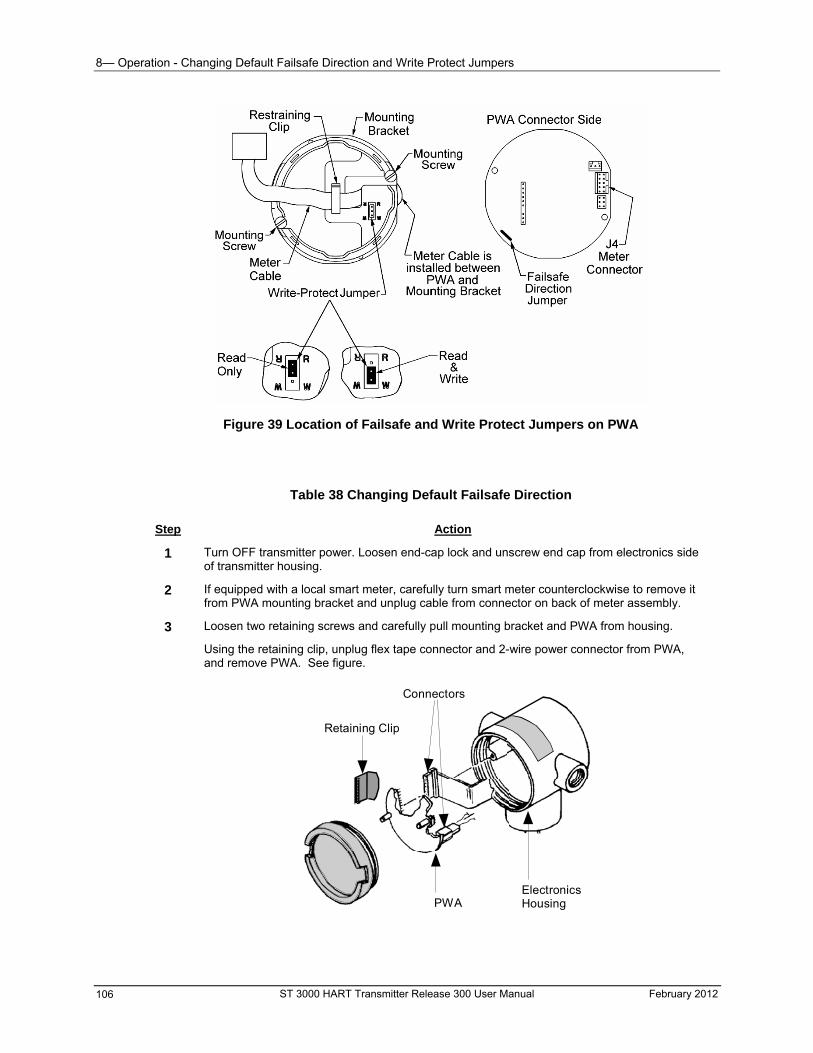
8— Operation - Changing Default Failsafe Direction and Write Protect Jumpers
Figure 39 Location of Failsafe and Write Protect Jumpers on PWA
Table 38 Changing Default Failsafe Direction
Step Action
1 Turn OFF transmitter power. Loosen end-cap lock and unscrew end cap from electronics side of transmitter housing.
2 If equipped with a local smart meter, carefully turn smart meter counterclockwise to remove it from PWA mounting bracket and unplug cable from connector on back of meter assembly.
3 Loosen two retaining screws and carefully pull mounting bracket and PWA from housing.
Using the retaining clip, unplug flex tape connector and 2-wire power connector from PWA, and remove PWA. See figure.
Connectors
Retaining Clip
PWAElectronicsHousing
ST 3000 HART Transmitter Release 300 User Manual February 2012 106
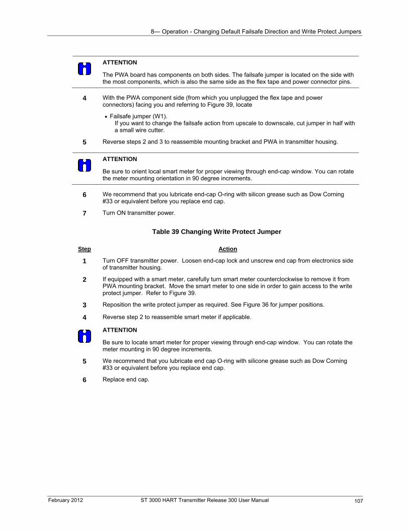
8— Operation - Changing Default Failsafe Direction and Write Protect Jumpers
February 2012 ST 3000 HART Transmitter Release 300 User Manual 107
ATTENTION
The PWA board has components on both sides. The failsafe jumper is located on the side with the most components, which is also the same side as the flex tape and power connector pins.
4 With the PWA component side (from which you unplugged the flex tape and power
connectors) facing you and referring to Figure 39, locate
Failsafe jumper (W1). If you want to change the failsafe action from upscale to downscale, cut jumper in half with a small wire cutter.
5 Reverse steps 2 and 3 to reassemble mounting bracket and PWA in transmitter housing.
ATTENTION
Be sure to orient local smart meter for proper viewing through end-cap window. You can rotate the meter mounting orientation in 90 degree increments.
6 We recommend that you lubricate end-cap O-ring with silicon grease such as Dow Corning
#33 or equivalent before you replace end cap.
7 Turn ON transmitter power.
Table 39 Changing Write Protect Jumper
Step Action
1 Turn OFF transmitter power. Loosen end-cap lock and unscrew end cap from electronics side of transmitter housing.
2 If equipped with a smart meter, carefully turn smart meter counterclockwise to remove it from PWA mounting bracket. Move the smart meter to one side in order to gain access to the write protect jumper. Refer to Figure 39.
3 Reposition the write protect jumper as required. See Figure 36 for jumper positions.
4 Reverse step 2 to reassemble smart meter if applicable.
ATTENTION
Be sure to locate smart meter for proper viewing through end-cap window. You can rotate the meter mounting in 90 degree increments.
5 We recommend that you lubricate end cap O-ring with silicone grease such as Dow Corning #33 or equivalent before you replace end cap.
6 Replace end cap.
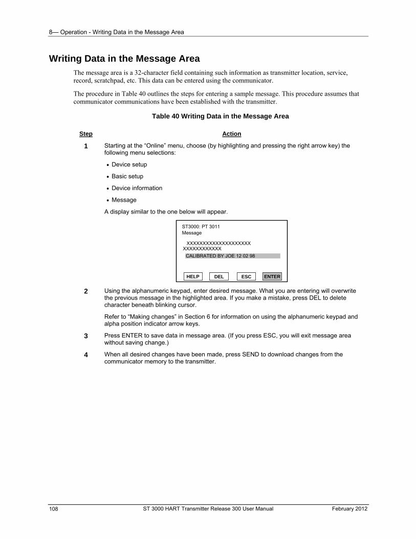
8— Operation - Writing Data in the Message Area
ST 3000 HART Transmitter Release 300 User Manual February 2012 108
Writing Data in the Message Area The message area is a 32-character field containing such information as transmitter location, service, record, scratchpad, etc. This data can be entered using the communicator.
The procedure in Table 40 outlines the steps for entering a sample message. This procedure assumes that communicator communications have been established with the transmitter.
Table 40 Writing Data in the Message Area
Step Action
1 Starting at the “Online” menu, choose (by highlighting and pressing the right arrow key) the following menu selections:
Device setup
Basic setup
Device information
Message
A display similar to the one below will appear.
ST3000: PT 3011 Message
XXXXXXXXXXXXXXXXXXXX
HELP ESCDEL ENTER
XXXXXXXXXXXX
CALIBRATED BY JOE 12 02 98
2 Using the alphanumeric keypad, enter desired message. What you are entering will overwrite the previous message in the highlighted area. If you make a mistake, press DEL to delete character beneath blinking cursor.
Refer to “Making changes” in Section 6 for information on using the alphanumeric keypad and alpha position indicator arrow keys.
3 Press ENTER to save data in message area. (If you press ESC, you will exit message area without saving change.)
4 When all desired changes have been made, press SEND to download changes from the communicator memory to the transmitter.
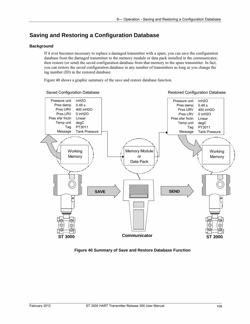
8— Operation - Saving and Restoring a Configuration Database
Saving and Restoring a Configuration Database
Background
If it ever becomes necessary to replace a damaged transmitter with a spare, you can save the configuration database from the damaged transmitter to the memory module or data pack installed in the communicator, then restore (or send) the saved configuration database from that memory to the spare transmitter. In fact, you can restore the saved configuration database in any number of transmitters as long as you change the tag number (ID) in the restored database.
Figure 40 shows a graphic summary of the save and restore database function.
SEND
Communicator
Memory Moduleor
Data Pack
ST 3000
Pressure unitPres dampPres URVPres LRV
Pres xfer fnctnTemp unit
TagMessage
inH2O0.48 s400 inH2O0 inH2OLineardegCPT3011Tank Pressure
Saved Configuration Database
ST 3000
WorkingMemory
Restored Configuration Database
SAVE
WorkingMemory
Pressure unitPres dampPres URVPres LRV
Pres xfer fnctnTemp unit
TagMessage
inH2O0.48 s400 inH2O0 inH2OLineardegCPT3011Tank Pressure
Figure 40 Summary of Save and Restore Database Function
February 2012 ST 3000 HART Transmitter Release 300 User Manual 109
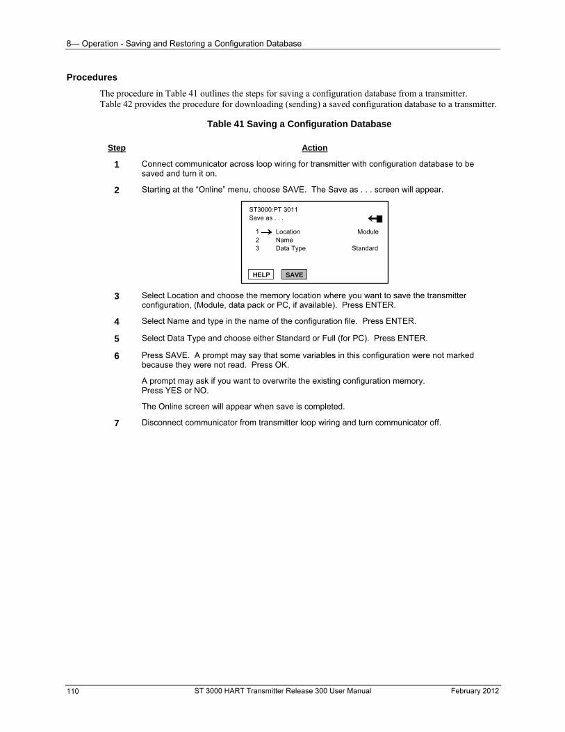
8— Operation - Saving and Restoring a Configuration Database
Procedures
The procedure in Table 41 outlines the steps for saving a configuration database from a transmitter. Table 42 provides the procedure for downloading (sending) a saved configuration database to a transmitter.
Table 41 Saving a Configuration Database
Step Action
1 Connect communicator across loop wiring for transmitter with configuration database to be saved and turn it on.
2 Starting at the “Online” menu, choose SAVE. The Save as . . . screen will appear.
ST3000:PT 3011 Save as . . .
2 3 Data Type Standard
HELP SAVE
1 Location Module Name
3 Select Location and choose the memory location where you want to save the transmitter configuration, (Module, data pack or PC, if available). Press ENTER.
4 Select Name and type in the name of the configuration file. Press ENTER.
5 Select Data Type and choose either Standard or Full (for PC). Press ENTER.
6 Press SAVE. A prompt may say that some variables in this configuration were not marked because they were not read. Press OK.
A prompt may ask if you want to overwrite the existing configuration memory. Press YES or NO.
The Online screen will appear when save is completed.
7 Disconnect communicator from transmitter loop wiring and turn communicator off.
ST 3000 HART Transmitter Release 300 User Manual February 2012 110
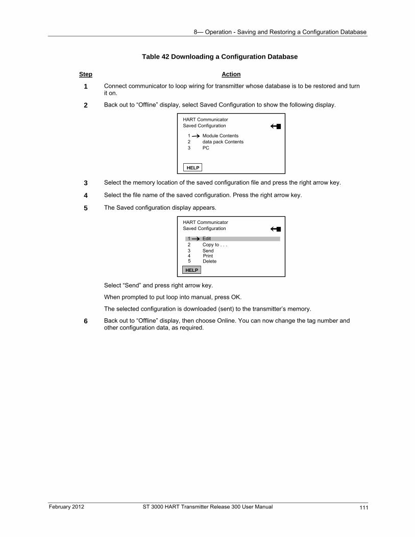
8— Operation - Saving and Restoring a Configuration Database
Table 42 Downloading a Configuration Database
Step Action
1 Connect communicator to loop wiring for transmitter whose database is to be restored and turn it on.
2 Back out to “Offline” display, select Saved Configuration to show the following display.
HART Communicator Saved Configuration
2 3
data pack ContentsPC
1 Module Contents
HELP
3 Select the memory location of the saved configuration file and press the right arrow key.
4 Select the file name of the saved configuration. Press the right arrow key.
5 The Saved configuration display appears.
HART Communicator Saved Configuration
1 2 3
EditCopy to . . .Send
HELP
4 5
Print Delete
Select “Send” and press right arrow key.
When prompted to put loop into manual, press OK.
The selected configuration is downloaded (sent) to the transmitter’s memory.
6 Back out to “Offline” display, then choose Online. You can now change the tag number and other configuration data, as required.
February 2012 ST 3000 HART Transmitter Release 300 User Manual 111
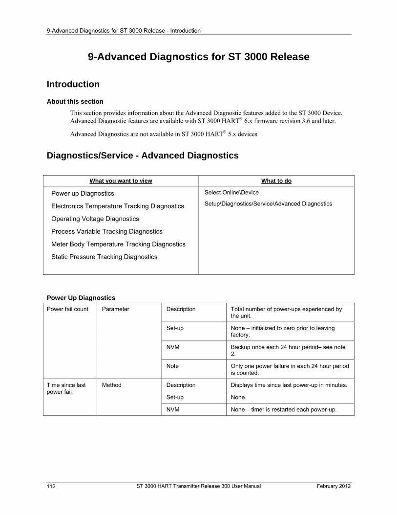
9-Advanced Diagnostics for ST 3000 Release - Introduction
9-Advanced Diagnostics for ST 3000 Release
Introduction
About this section
This section provides information about the Advanced Diagnostic features added to the ST 3000 Device. Advanced Diagnostic features are available with ST 3000 HART 6.x firmware revision 3.6 and later.
Advanced Diagnostics are not available in ST 3000 HART 5.x devices
Diagnostics/Service - Advanced Diagnostics
What you want to view What to do
Power up Diagnostics
Electronics Temperature Tracking Diagnostics
Select Online\Device
Operating Voltage Diagnostics
Process Variable Tracking Diagnostics
Meter Body Temperature Tracking Diagnostics
Static Pressure Tracking Diagnostics
Setup\Diagnostics/Service\Advanced Diagnostics
Power Up Diagnostics
Description Total number of power-ups experienced by the unit.
Set-up None – initialized to zero prior to leaving factory.
Power fail count Parameter
NVM Backup once each 24 hour period– see note 2.
Note Only one power failure in each 24 hour period is counted.
Description Displays time since last power-up in minutes. Method
Set-up None.
Time since last power fail
NVM None – timer is restarted each power-up.
ST 3000 HART Transmitter Release 300 User Manual February 2012 112
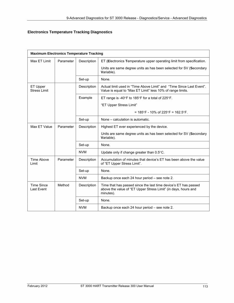
9-Advanced Diagnostics for ST 3000 Release - Diagnostics/Service - Advanced Diagnostics
Electronics Temperature Tracking Diagnostics
Maximum Electronics Temperature Tracking
ET (Electronics Temperature upper operating limit from specification. Description
Units are same degree units as has been selected for SV (Secondary Variable).
Max ET Limit Parameter
Set-up None.
Description Actual limit used in “Time Above Limit” and “Time Since Last Event”. Value is equal to “Max ET Limit” less 10% of range limits.
Example
ET Upper Stress Limit
ET range is -40F to 185F for a total of 225F.
“ET Upper Stress Limit”
= 185F - 10% of 225F = 162.5F.
Set-up None – calculation is automatic.
Description Highest ET ever experienced by the device.
Units are same degree units as has been selected for SV (Secondary Variable).
Set-up None.
Max ET Value Parameter
NVM Update only if change greater than 0.5C.
Description Accumulation of minutes that device’s ET has been above the value of “ET Upper Stress Limit”.
Parameter Time Above Limit
Set-up None.
NVM Backup once each 24 hour period – see note 2.
Description Time that has passed since the last time device’s ET has passed above the value of “ET Upper Stress Limit” (in days, hours and minutes).
Set-up None.
Method Time Since Last Event
NVM Backup once each 24 hour period – see note 2.
February 2012 ST 3000 HART Transmitter Release 300 User Manual 113
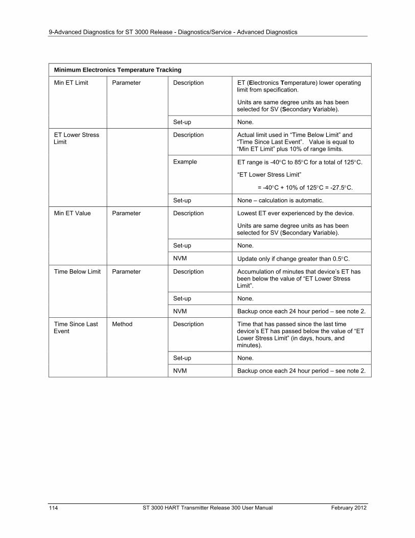
9-Advanced Diagnostics for ST 3000 Release - Diagnostics/Service - Advanced Diagnostics
Minimum Electronics Temperature Tracking
Description ET (Electronics Temperature) lower operating limit from specification.
Units are same degree units as has been selected for SV (Secondary Variable).
Min ET Limit Parameter
Set-up None.
Description Actual limit used in “Time Below Limit” and “Time Since Last Event”. Value is equal to “Min ET Limit” plus 10% of range limits.
Example
ET Lower Stress Limit
ET range is -40C to 85C for a total of 125C.
“ET Lower Stress Limit”
= -40C + 10% of 125C = -27.5C.
Set-up None – calculation is automatic.
Description Lowest ET ever experienced by the device.
Units are same degree units as has been selected for SV (Secondary Variable).
Set-up None.
Min ET Value Parameter
NVM Update only if change greater than 0.5C.
Description Accumulation of minutes that device’s ET has been below the value of “ET Lower Stress Limit”.
Time Below Limit Parameter
Set-up None.
NVM Backup once each 24 hour period – see note 2.
Description Time that has passed since the last time device’s ET has passed below the value of “ET Lower Stress Limit” (in days, hours, and minutes).
Method Time Since Last Event
Set-up None.
NVM Backup once each 24 hour period – see note 2.
ST 3000 HART Transmitter Release 300 User Manual February 2012 114
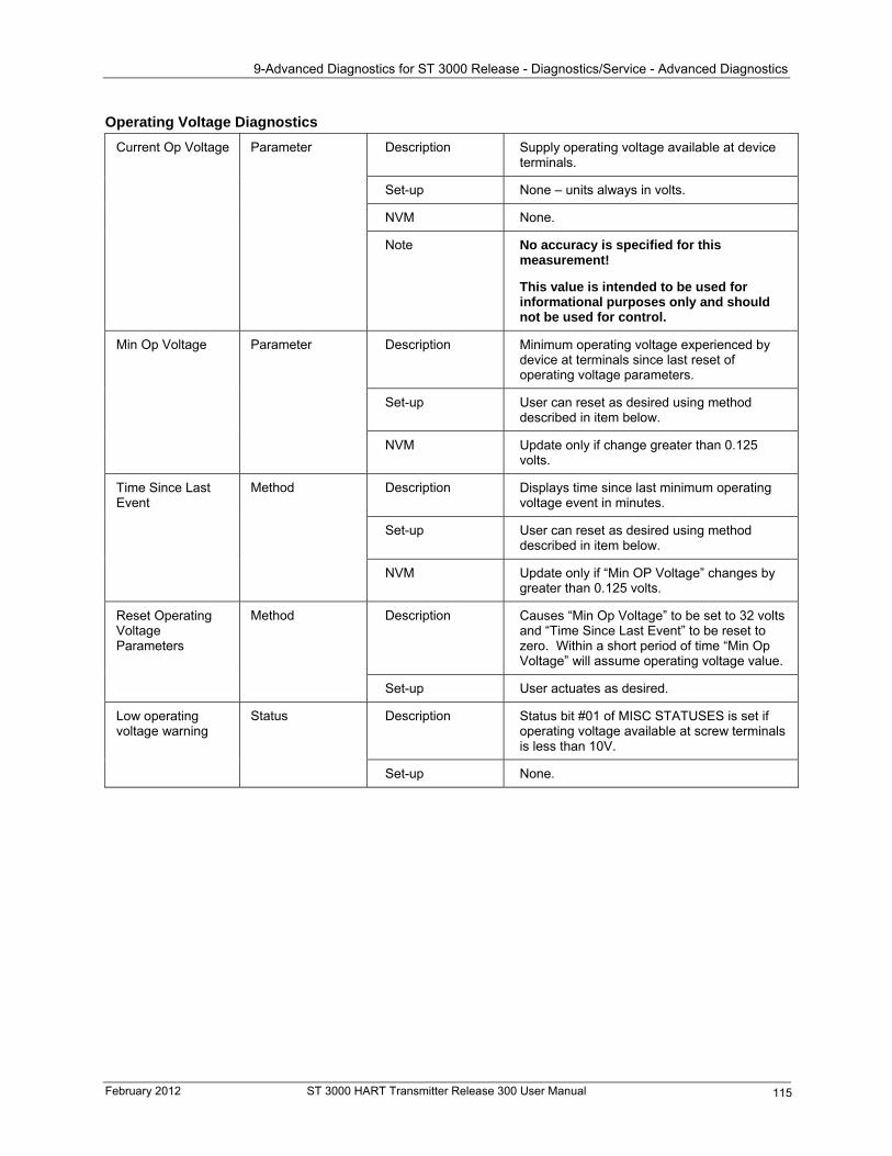
9-Advanced Diagnostics for ST 3000 Release - Diagnostics/Service - Advanced Diagnostics
Operating Voltage Diagnostics
Description Supply operating voltage available at device terminals.
Set-up None – units always in volts.
Current Op Voltage Parameter
NVM None.
No accuracy is specified for this measurement!
Note
This value is intended to be used for informational purposes only and should not be used for control.
Description Minimum operating voltage experienced by device at terminals since last reset of operating voltage parameters.
Min Op Voltage Parameter
Set-up User can reset as desired using method described in item below.
NVM Update only if change greater than 0.125 volts.
Description Displays time since last minimum operating voltage event in minutes.
Set-up User can reset as desired using method described in item below.
Time Since Last Event
Method
NVM Update only if “Min OP Voltage” changes by greater than 0.125 volts.
Description Causes “Min Op Voltage” to be set to 32 volts and “Time Since Last Event” to be reset to zero. Within a short period of time “Min Op Voltage” will assume operating voltage value.
Method Reset Operating Voltage Parameters
Set-up User actuates as desired.
Description Status bit #01 of MISC STATUSES is set if operating voltage available at screw terminals is less than 10V.
Low operating voltage warning
Status
Set-up None.
February 2012 ST 3000 HART Transmitter Release 300 User Manual 115
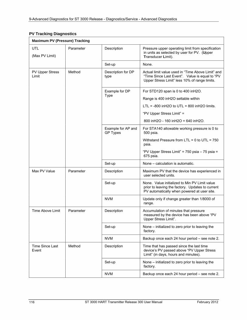
9-Advanced Diagnostics for ST 3000 Release - Diagnostics/Service - Advanced Diagnostics
PV Tracking Diagnostics
Maximum PV (Pressure) Tracking
Description Pressure upper operating limit from specification in units as selected by user for PV. (Upper Transducer Limit).
UTL
(Max PV Limit)
Parameter
Set-up None.
Description for DP type
Actual limit value used in “Time Above Limit” and “Time Since Last Event”. Value is equal to “PV Upper Stress Limit” less 10% of range limits.
Method PV Upper Stress Limit
For STD120 span is 0 to 400 inH2O. Example for DP Type
Range is 400 inH2O settable within
LTL = -800 inH2O to UTL = 800 inH2O limits.
“PV Upper Stress Limit” =
800 inH2O - 160 inH2O = 640 inH2O.
Example for AP and GP Types
For STA140 allowable working pressure is 0 to 500 psia.
Withstand Pressure from LTL = 0 to UTL = 750 psia.
“PV Upper Stress Limit” = 750 psia – 75 psia = 675 psia.
Set-up None – calculation is automatic.
Description Maximum PV that the device has experienced in user selected units.
Max PV Value Parameter
Set-up None. Value initialized to Min PV Limit value prior to leaving the factory. Updates to current PV automatically when powered at user site.
NVM Update only if change greater than 1/8000 of range.
Description Accumulation of minutes that pressure measured by the device has been above “PV Upper Stress Limit”.
Time Above Limit Parameter
Set-up None – initialized to zero prior to leaving the factory.
NVM Backup once each 24 hour period – see note 2.
Description Time that has passed since the last time device’s PV passed above “PV Upper Stress Limit” (in days, hours and minutes).
Set-up None – initialized to zero prior to leaving the factory.
Method Time Since Last Event
NVM Backup once each 24 hour period – see note 2.
ST 3000 HART Transmitter Release 300 User Manual February 2012 116
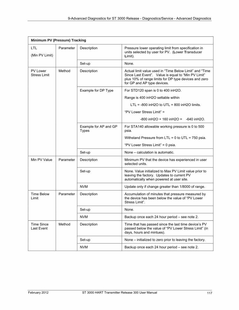
9-Advanced Diagnostics for ST 3000 Release - Diagnostics/Service - Advanced Diagnostics
Minimum PV (Pressure) Tracking
Description Pressure lower operating limit from specification in units selected by user for PV. (Lower Transducer Limit).
LTL
(Min PV Limit)
Parameter
Set-up None.
Description
Actual limit value used in “Time Below Limit” and “Time Since Last Event”. Value is equal to “Min PV Limit” plus 10% of range limits for DP type devices and zero for GP and AP type devices.
Example for DP Type For STD120 span is 0 to 400 inH2O.
Range is 400 inH2O settable within
LTL = -800 inH2O to UTL = 800 inH2O limits.
“PV Lower Stress Limit” =
-800 inH2O + 160 inH2O = -640 inH2O.
Example for AP and GP Types
For STA140 allowable working pressure is 0 to 500 psia.
Withstand Pressure from LTL = 0 to UTL = 750 psia.
“PV Lower Stress Limit” = 0 psia.
PV Lower Stress Limit
Method
Set-up None – calculation is automatic.
Description Minimum PV that the device has experienced in user selected units.
Min PV Value Parameter
Set-up None. Value initialized to Max PV Limit value prior to leaving the factory. Updates to current PV automatically when powered at user site.
NVM Update only if change greater than 1/8000 of range.
Description Accumulation of minutes that pressure measured by the device has been below the value of “PV Lower Stress Limit”.
Parameter Time Below Limit
Set-up None.
NVM Backup once each 24 hour period – see note 2.
Description Time that has passed since the last time device’s PV passed below the value of “PV Lower Stress Limit” (in days, hours and mintues).
Method Time Since Last Event
Set-up None – initialized to zero prior to leaving the factory.
NVM Backup once each 24 hour period – see note 2.
February 2012 ST 3000 HART Transmitter Release 300 User Manual 117
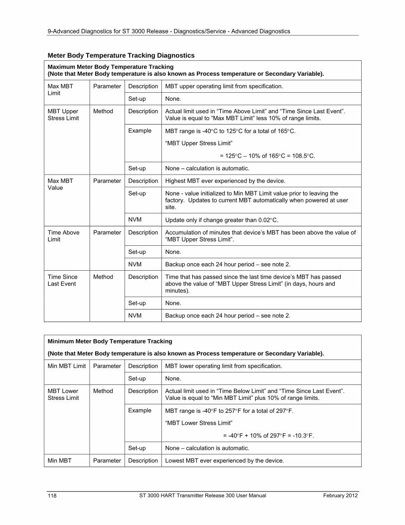
9-Advanced Diagnostics for ST 3000 Release - Diagnostics/Service - Advanced Diagnostics
Meter Body Temperature Tracking Diagnostics
Maximum Meter Body Temperature Tracking (Note that Meter Body temperature is also known as Process temperature or Secondary Variable).
Description MBT upper operating limit from specification. Parameter Max MBT Limit
Set-up None.
Description Actual limit used in “Time Above Limit” and “Time Since Last Event”. Value is equal to “Max MBT Limit” less 10% of range limits.
Example MBT range is -40C to 125C for a total of 165C.
“MBT Upper Stress Limit”
= 125C – 10% of 165C = 108.5C.
MBT Upper Stress Limit
Method
Set-up None – calculation is automatic.
Description Highest MBT ever experienced by the device. Parameter
Set-up None - value initialized to Min MBT Limit value prior to leaving the factory. Updates to current MBT automatically when powered at user site.
Max MBT Value
NVM Update only if change greater than 0.02C.
Description Accumulation of minutes that device’s MBT has been above the value of “MBT Upper Stress Limit”.
Parameter Time Above Limit
Set-up None.
NVM Backup once each 24 hour period – see note 2.
Description Time that has passed since the last time device’s MBT has passed above the value of “MBT Upper Stress Limit” (in days, hours and minutes).
Set-up None.
Method Time Since Last Event
NVM Backup once each 24 hour period – see note 2.
Minimum Meter Body Temperature Tracking
(Note that Meter Body temperature is also known as Process temperature or Secondary Variable).
Description MBT lower operating limit from specification. Min MBT Limit Parameter
Set-up None.
Description Actual limit used in “Time Below Limit” and “Time Since Last Event”. Value is equal to “Min MBT Limit” plus 10% of range limits.
Example MBT range is -40F to 257F for a total of 297F.
“MBT Lower Stress Limit”
= -40F + 10% of 297F = -10.3F.
MBT Lower Stress Limit
Method
Set-up None – calculation is automatic.
Min MBT Parameter Description Lowest MBT ever experienced by the device.
ST 3000 HART Transmitter Release 300 User Manual February 2012 118
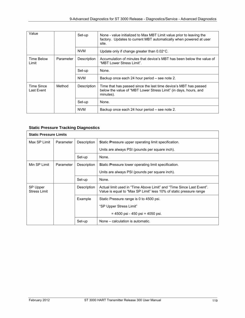
9-Advanced Diagnostics for ST 3000 Release - Diagnostics/Service - Advanced Diagnostics
Set-up None - value initialized to Max MBT Limit value prior to leaving the factory. Updates to current MBT automatically when powered at user site.
Value
NVM Update only if change greater than 0.02C.
Description Accumulation of minutes that device’s MBT has been below the value of “MBT Lower Stress Limit”.
Parameter Time Below Limit
Set-up None.
NVM Backup once each 24 hour period – see note 2.
Description Time that has passed since the last time device’s MBT has passed below the value of “MBT Lower Stress Limit” (in days, hours, and minutes).
Set-up None.
Method Time Since Last Event
NVM Backup once each 24 hour period – see note 2.
Static Pressure Tracking Diagnostics
Static Pressure Limits
Static Pressure upper operating limit specification. Description
Units are always PSI (pounds per square inch).
Max SP Limit Parameter
Set-up None.
Static Pressure lower operating limit specification. Description
Units are always PSI (pounds per square inch).
Min SP Limit Parameter
Set-up None.
Description Actual limit used in “Time Above Limit” and “Time Since Last Event”. Value is equal to “Max SP Limit” less 10% of static pressure range
SP Upper Stress Limit
Example Static Pressure range is 0 to 4500 psi.
“SP Upper Stress Limit”
= 4500 psi - 450 psi = 4050 psi.
Set-up None – calculation is automatic.
February 2012 ST 3000 HART Transmitter Release 300 User Manual 119
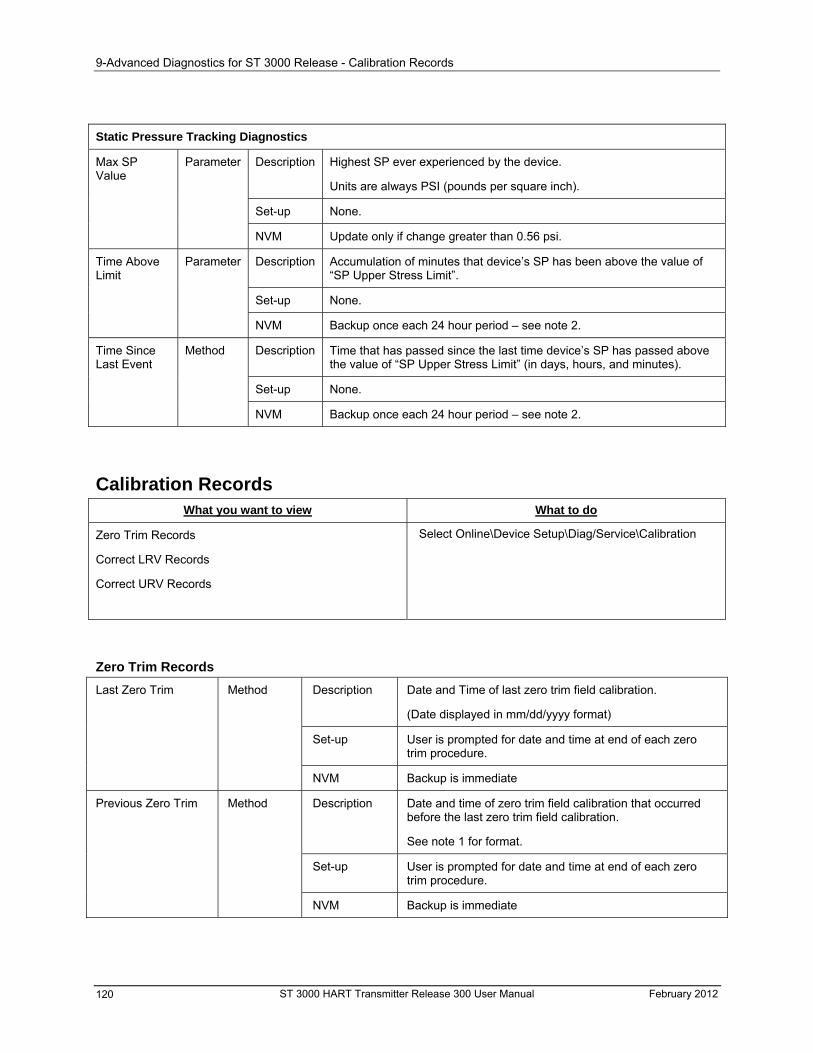
9-Advanced Diagnostics for ST 3000 Release - Calibration Records
Static Pressure Tracking Diagnostics
Description Highest SP ever experienced by the device.
Units are always PSI (pounds per square inch).
Set-up None.
Max SP Value
Parameter
NVM Update only if change greater than 0.56 psi.
Description Accumulation of minutes that device’s SP has been above the value of “SP Upper Stress Limit”.
Parameter Time Above Limit
Set-up None.
NVM Backup once each 24 hour period – see note 2.
Description Time that has passed since the last time device’s SP has passed above the value of “SP Upper Stress Limit” (in days, hours, and minutes).
Set-up None.
Method Time Since Last Event
NVM Backup once each 24 hour period – see note 2.
Calibration Records What you want to view What to do
Select Online\Device Setup\Diag/Service\Calibration Zero Trim Records
Correct LRV Records
Correct URV Records
Zero Trim Records
Description Date and Time of last zero trim field calibration.
(Date displayed in mm/dd/yyyy format)
Last Zero Trim Method
Set-up User is prompted for date and time at end of each zero trim procedure.
NVM Backup is immediate
Description Date and time of zero trim field calibration that occurred before the last zero trim field calibration.
See note 1 for format.
Set-up
Previous Zero Trim Method
User is prompted for date and time at end of each zero trim procedure.
NVM Backup is immediate
ST 3000 HART Transmitter Release 300 User Manual February 2012 120
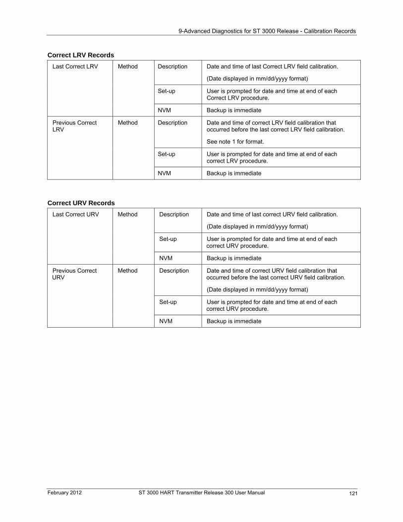
9-Advanced Diagnostics for ST 3000 Release - Calibration Records
Correct LRV Records
Description Date and time of last Correct LRV field calibration.
(Date displayed in mm/dd/yyyy format)
Last Correct LRV Method
Set-up User is prompted for date and time at end of each Correct LRV procedure.
NVM Backup is immediate
Description Date and time of correct LRV field calibration that occurred before the last correct LRV field calibration.
See note 1 for format.
Set-up
Method Previous Correct LRV
User is prompted for date and time at end of each correct LRV procedure.
NVM Backup is immediate
Correct URV Records
Description Date and time of last correct URV field calibration.
(Date displayed in mm/dd/yyyy format)
Last Correct URV Method
Set-up User is prompted for date and time at end of each correct URV procedure.
NVM Backup is immediate
Description Date and time of correct URV field calibration that occurred before the last correct URV field calibration.
(Date displayed in mm/dd/yyyy format)
Set-up User is prompted for date and time at end of each correct URV procedure.
Method Previous Correct URV
NVM Backup is immediate
February 2012 ST 3000 HART Transmitter Release 300 User Manual 121
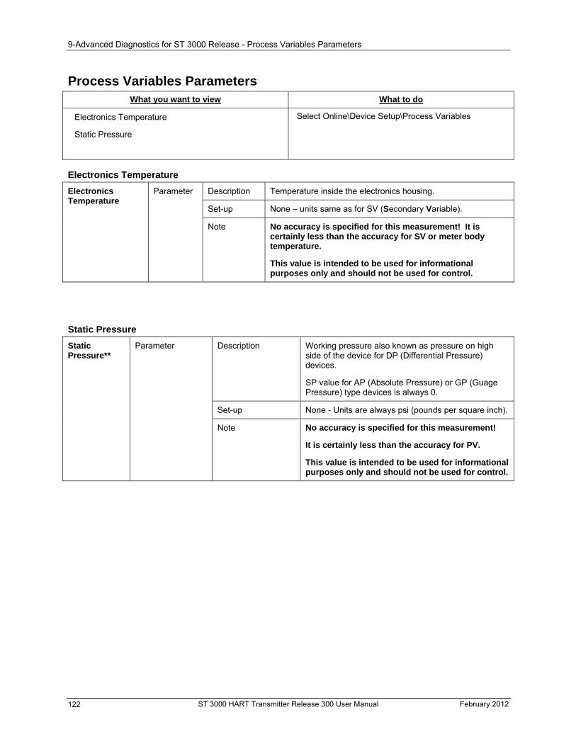
9-Advanced Diagnostics for ST 3000 Release - Process Variables Parameters
Process Variables Parameters What you want to view What to do
Electronics Temperature
Static Pressure
Select Online\Device Setup\Process Variables
Electronics Temperature
Description Temperature inside the electronics housing.
Set-up None – units same as for SV (Secondary Variable).
Electronics Temperature
Parameter
Note No accuracy is specified for this measurement! It is certainly less than the accuracy for SV or meter body temperature.
This value is intended to be used for informational purposes only and should not be used for control.
Static Pressure
Description Working pressure also known as pressure on high side of the device for DP (Differential Pressure) devices.
SP value for AP (Absolute Pressure) or GP (Guage Pressure) type devices is always 0.
Static Pressure**
Parameter
None - Units are always psi (pounds per square inch). Set-up
Note No accuracy is specified for this measurement!
It is certainly less than the accuracy for PV.
This value is intended to be used for informational purposes only and should not be used for control.
ST 3000 HART Transmitter Release 300 User Manual February 2012 122
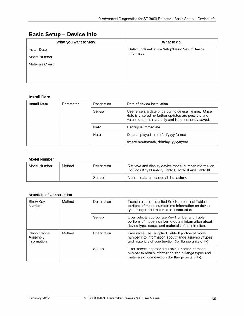
9-Advanced Diagnostics for ST 3000 Release - Basic Setup – Device Info
Basic Setup – Device Info What you want to view What to do
Install Date
Model Number
Materials Constr
Select Online\Device Setup\Basic Setup\Device Information
Install Date
Description Date of device installation. Install Date Parameter
Set-up User enters a date once during device lifetime. Once date is entered no further updates are possible and value becomes read only and is permanently saved.
NVM Backup is immediate.
Note Date displayed in mm/dd/yyyy format
where mm=month, dd=day, yyyy=year
Model Number
Description Retrieve and display device model number information. Includes Key Number, Table I, Table II and Table III.
Model Number Method
Set-up None – data preloaded at the factory.
Materials of Construction
Description Translates user supplied Key Number and Table I portions of model number into information on device type, range, and materials of contruction
Method Show Key Number
Set-up User selects appropriate Key Number and Table I portions of model number to obtain information about device type, range, and materials of construction.
Description Translates user supplied Table II portion of model number into information about flange assembly types and materials of construction (for flange units only)
Show Flange Assembly Information
Method
Set-up User selects appropriate Table II portion of model number to obtain information about flange types and materials of construction (for flange units only).
February 2012 ST 3000 HART Transmitter Release 300 User Manual 123
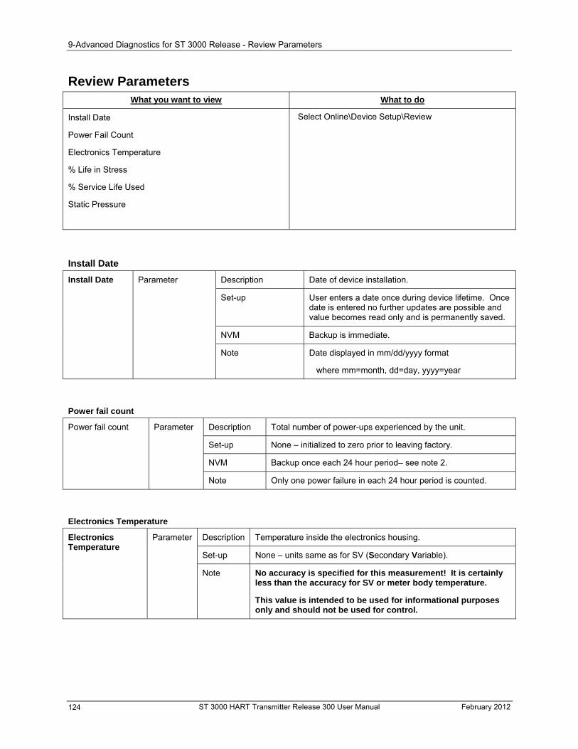
9-Advanced Diagnostics for ST 3000 Release - Review Parameters
Review Parameters What you want to view What to do
Install Date
Power Fail Count
Electronics Temperature
% Life in Stress
% Service Life Used
Static Pressure
Select Online\Device Setup\Review
Install Date
Description Date of device installation. Install Date Parameter
Set-up User enters a date once during device lifetime. Once date is entered no further updates are possible and value becomes read only and is permanently saved.
NVM Backup is immediate.
Note Date displayed in mm/dd/yyyy format
where mm=month, dd=day, yyyy=year
Power fail count
Description Total number of power-ups experienced by the unit. Power fail count Parameter
Set-up None – initialized to zero prior to leaving factory.
NVM Backup once each 24 hour period– see note 2.
Note Only one power failure in each 24 hour period is counted.
Electronics Temperature
Description Temperature inside the electronics housing.
Set-up None – units same as for SV (Secondary Variable).
Electronics Temperature
Parameter
No accuracy is specified for this measurement! It is certainly less than the accuracy for SV or meter body temperature.
Note
This value is intended to be used for informational purposes only and should not be used for control.
ST 3000 HART Transmitter Release 300 User Manual February 2012 124
9-Advanced Diagnostics for ST 3000 Release - Review Parameters
% Service Life in Stress
Description Percent of service life spent in stressful conditions. Indicates the % of service life where one or more of PV, static pressure, meter body temperature or electronics temperature are within 10% of respective range limits.
% Service Life in Stress
Parameter
Set-up None.
NVM Backup once each 24 hour period– see note 2.
% Service Life Used
Description Value is based on electronics temperature. Service life accumulates faster at higher temperatures with an exponential relationship. At 25 degrees C service life is expected to be approximately 27 years.
Set-up
% Service Life Used
Parameter
None.
NVM Backup once each 24 hour period– see note 2.
February 2012 ST 3000 HART Transmitter Release 300 User Manual 125
9-Advanced Diagnostics for ST 3000 Release - Review Parameters
Static Pressure
Description Working pressure also known as pressure on high side of the device for DP (Differential Pressure) devices.
SP value for AP (Absolute Pressure) or GP (Guage Pressure) type devices is always 0.
Static Pressure**
Parameter
None - Units are always psi (pounds per square inch). Set-up
No accuracy is specified for this measurement! Note
It is certainly less than the accuracy for PV.
This value is intended to be used for informational purposes only and should not be used for control.
Note 1: Time and date format
Date and time are displayed in mm/dd/yyyy format where mm=month, dd=day, yyyy=year and in HH:MM:SS format where HH=hours, MM=minutes, SS=seconds.
Note 2: These parameters are backed up in NVM memory once per day so that the maximum numbers of writes, as specified by the NVM’s manufacturer, are not exceeded during the lifetime of the pressure transmitter. This means that when power to the device is lost and then re-applied the value reverts back to the value that existed when last backed up to NVM. If the last backup had occurred 23 hours and 59 minutes ago then a full days worth of data would be lost.
Note 3: ** Future Feature to be added for DP meter body type; static pressure is 0.0 for AP and GP type meter bodies.
ST 3000 HART Transmitter Release 300 User Manual February 2012 126
10— Maintenance - Introduction
10— Maintenance
Introduction
About this section
This section provides information about preventive maintenance routines and replacing damaged parts. The topics covered in this section are:
Preventive maintenance of the meter body barrier diaphragms and process piping to the transmitter.
Replacement of damaged parts such as the transmitter PWA and meter body.
Preventive Maintenance
Maintenance routines and schedules
The ST 3000 transmitter itself does not require any specific maintenance routine at regularly scheduled intervals. However, you should consider carrying out these typical inspection and maintenance routines on a schedule that is dictated by the characteristics of the process medium being measured and whether blow-down facilities or purge systems are being used.
Check piping for leaks.
Clear the piping of sediment or other foreign matter.
Clean the transmitter’s pressure chambers including the barrier diaphragms.
Inspecting and Cleaning Barrier Diaphragms Depending on the characteristics of the process medium being measured, sediment or other foreign particles may collect in the process head cavity/chamber and cause faulty measurement. In addition, the barrier diaphragm or diaphragms in the transmitter’s meter body may become coated with a residue from the process medium. The latter is also true for external diaphragms on flange mount and remote seal type transmitters.
In most cases, you can readily remove the process head or heads from the transmitter’s meter body to clean the process head cavity and inspect the barrier diaphragm or diaphragms. For flange mount and remote seal diaphragms, you may only need to run a purge line in the tank to rinse off the face of the diaphragm.
Procedure
The procedure in Table 43 outlines the general steps for inspecting and cleaning barrier diaphragms. You may have to modify the steps to meet your particular process or transmitter model requirements. Figure 42 shows an exploded view of a DP transmitter’s meter body for reference.
February 2012 ST 3000 HART Transmitter Release 300 User Manual 127
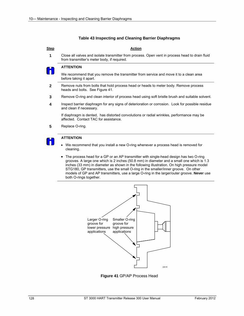
10— Maintenance - Inspecting and Cleaning Barrier Diaphragms
Table 43 Inspecting and Cleaning Barrier Diaphragms
Step Action
1 Close all valves and isolate transmitter from process. Open vent in process head to drain fluid from transmitter’s meter body, if required.
ATTENTION
We recommend that you remove the transmitter from service and move it to a clean area before taking it apart.
2 Remove nuts from bolts that hold process head or heads to meter body. Remove process heads and bolts. See Figure 41.
3 Remove O-ring and clean interior of process head using soft bristle brush and suitable solvent.
4 Inspect barrier diaphragm for any signs of deterioration or corrosion. Look for possible residue and clean if necessary.
If diaphragm is dented, has distorted convolutions or radial wrinkles, performance may be affected. Contact TAC for assistance.
5 Replace O-ring.
ATTENTION
We recommend that you install a new O-ring whenever a process head is removed for cleaning.
The process head for a GP or an AP transmitter with single-head design has two O-ring grooves. A large one which is 2 inches (50.8 mm) in diameter and a small one which is 1.3 inches (33 mm) in diameter as shown in the following illustration. On high pressure model STG180, GP transmitters, use the small O-ring in the smaller/inner groove. On other models of GP and AP transmitters, use a large O-ring in the larger/outer groove. Never use both O-rings together.
Larger O-ring groove for lower pressure applications
Smaller O-ring groove for high pressure applications
22518
Figure 41 GP/AP Process Head
ST 3000 HART Transmitter Release 300 User Manual February 2012 128
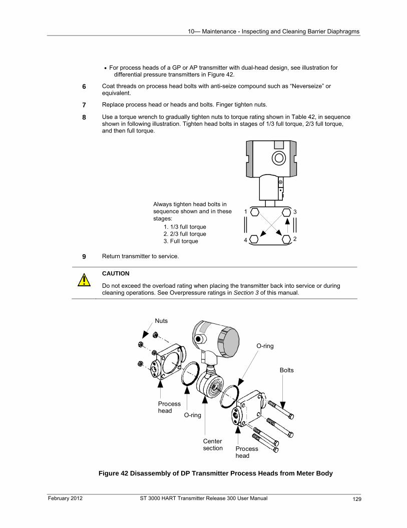
10— Maintenance - Inspecting and Cleaning Barrier Diaphragms
February 2012 ST 3000 HART Transmitter Release 300 User Manual 129
For process heads of a GP or AP transmitter with dual-head design, see illustration for differential pressure transmitters in Figure 42.
6 Coat threads on process head bolts with anti-seize compound such as “Neverseize” or equivalent.
7 Replace process head or heads and bolts. Finger tighten nuts.
8 Use a torque wrench to gradually tighten nuts to torque rating shown in Table 42, in sequence shown in following illustration. Tighten head bolts in stages of 1/3 full torque, 2/3 full torque, and then full torque.
1
24
3Always tighten head bolts insequence shown and in thesestages:
1. 1/3 full torque2. 2/3 full torque3. Full torque
9 Return transmitter to service.
CAUTION
Do not exceed the overload rating when placing the transmitter back into service or during cleaning operations. See Overpressure ratings in Section 3 of this manual.
Nuts
Processhead
O-ring
Centersection Process
head
O-ring
Bolts
Figure 42 Disassembly of DP Transmitter Process Heads from Meter Body
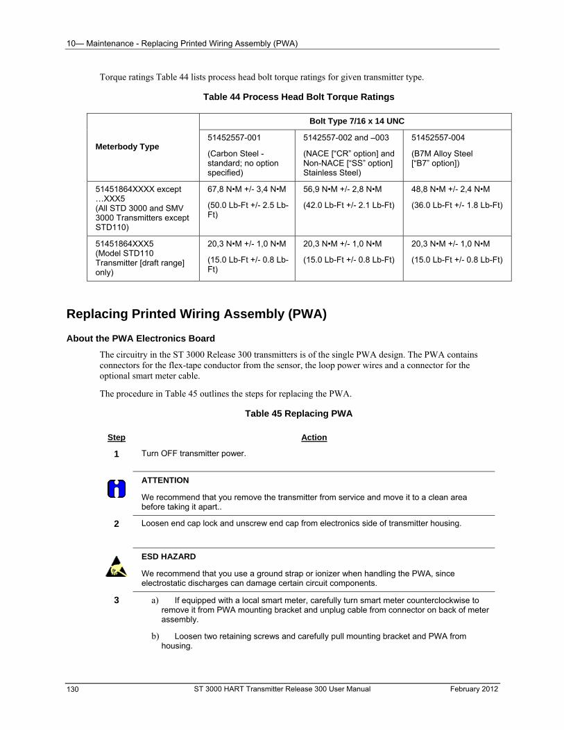
10— Maintenance - Replacing Printed Wiring Assembly (PWA)
Torque ratings Table 44 lists process head bolt torque ratings for given transmitter type.
Table 44 Process Head Bolt Torque Ratings
Bolt Type 7/16 x 14 UNC
Meterbody Type 51452557-001
(Carbon Steel - standard; no option specified)
5142557-002 and –003
(NACE [“CR” option] and Non-NACE [“SS” option] Stainless Steel)
51452557-004
(B7M Alloy Steel [“B7” option])
51451864XXXX except …XXX5 (All STD 3000 and SMV 3000 Transmitters except STD110)
67,8 N•M +/- 3,4 N•M 56,9 N•M +/- 2,8 N•M 48,8 N•M +/- 2,4 N•M
(50.0 Lb-Ft +/- 2.5 Lb-Ft)
(42.0 Lb-Ft +/- 2.1 Lb-Ft) (36.0 Lb-Ft +/- 1.8 Lb-Ft)
51451864XXX5 (Model STD110 Transmitter [draft range] only)
20,3 N•M +/- 1,0 N•M
(15.0 Lb-Ft +/- 0.8 Lb-Ft)
20,3 N•M +/- 1,0 N•M
(15.0 Lb-Ft +/- 0.8 Lb-Ft)
20,3 N•M +/- 1,0 N•M
(15.0 Lb-Ft +/- 0.8 Lb-Ft)
Replacing Printed Wiring Assembly (PWA)
About the PWA Electronics Board
The circuitry in the ST 3000 Release 300 transmitters is of the single PWA design. The PWA contains connectors for the flex-tape conductor from the sensor, the loop power wires and a connector for the optional smart meter cable.
The procedure in Table 45 outlines the steps for replacing the PWA.
Table 45 Replacing PWA
Step Action
1 Turn OFF transmitter power.
ATTENTION
We recommend that you remove the transmitter from service and move it to a clean area before taking it apart..
2 Loosen end cap lock and unscrew end cap from electronics side of transmitter housing.
ESD HAZARD
We recommend that you use a ground strap or ionizer when handling the PWA, since electrostatic discharges can damage certain circuit components.
a) If equipped with a local smart meter, carefully turn smart meter counterclockwise to remove it from PWA mounting bracket and unplug cable from connector on back of meter assembly.
b) Loosen two retaining screws and carefully pull mounting bracket and PWA from housing.
3
ST 3000 HART Transmitter Release 300 User Manual February 2012 130
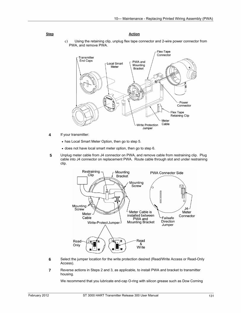
10— Maintenance - Replacing Printed Wiring Assembly (PWA)
February 2012 ST 3000 HART Transmitter Release 300 User Manual 131
Step Action
c) Using the retaining clip, unplug flex tape connector and 2-wire power connector from PWA, and remove PWA.
4 If your transmitter:
has Local Smart Meter Option, then go to step 5.
does not have local smart meter option, then go to step 6.
5 Unplug meter cable from J4 connector on PWA, and remove cable from restraining clip. Plug cable into J4 connector on replacement PWA. Route cable through slot and under restraining clip.
6 Select the jumper location for the write protection desired (Read/Write Access or Read-Only Access).
7 Reverse actions in Steps 2 and 3, as applicable, to install PWA and bracket to transmitter housing.
We recommend that you lubricate end-cap O-ring with silicon grease such as Dow Corning
10— Maintenance - Replacing Printed Wiring Assembly (PWA)
Step Action
#33 or equivalent before you replace end cap.
8 Recalibrate transmitter. Refer to Section 10 for proper procedure.
ATTENTION
Be sure to orient local smart meter for proper viewing through end-cap window. You can rotate the meter mounting orientation in 90 degree increments.
9 Return transmitter to service and turn ON power.
10 If applicable, verify local smart meter configuration data. Reconfigure selected engineering units and lower and upper display range values as required. (See Appendix A for details.)
ST 3000 HART Transmitter Release 300 User Manual February 2012 132
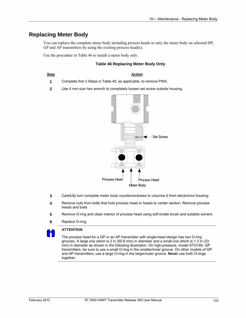
10— Maintenance - Replacing Meter Body
Replacing Meter Body You can replace the complete meter body including process heads or only the meter body on selected DP, GP and AP transmitters by using the existing process head(s).
Use the procedure in Table 46 to install a meter body only.
Table 46 Replacing Meter Body Only
Step Action
1 Complete first 3 Steps in Table 45, as applicable, to remove PWA.
2 Use 4 mm size hex wrench to completely loosen set screw outside housing.
Process Head Process Head
Meter Body
Set Screw
3 Carefully turn complete meter body counterclockwise to unscrew it from electronics housing.
4 Remove nuts from bolts that hold process head or heads to center section. Remove process heads and bolts
5 Remove O-ring and clean interior of process head using soft bristle brush and suitable solvent.
6 Replace O-ring.
ATTENTION
The process head for a GP or an AP transmitter with single-head design has two O-ring grooves. A large one which is 2 in (50.8 mm) in diameter and a small one which is 1.3 in (33 mm) in diameter as shown in the following illustration. On high-pressure, model STG180, GP transmitters, be sure to use a small O-ring in the smaller/inner groove. On other models of GP and AP transmitters, use a large O-ring in the larger/outer groove. Never use both O-rings together.
February 2012 ST 3000 HART Transmitter Release 300 User Manual 133
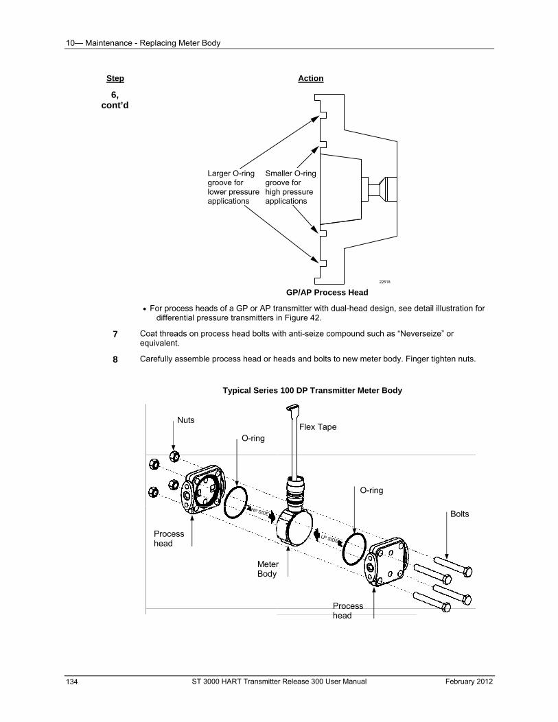
10— Maintenance - Replacing Meter Body
ST 3000 HART Transmitter Release 300 User Manual February 2012 134
Step Action
6, cont’d
Larger O-ring groove for lower pressure applications
Smaller O-ring groove for high pressure applications
22518 GP/AP Process Head
For process heads of a GP or AP transmitter with dual-head design, see detail illustration for differential pressure transmitters in Figure 42.
7 Coat threads on process head bolts with anti-seize compound such as “Neverseize” or equivalent.
8 Carefully assemble process head or heads and bolts to new meter body. Finger tighten nuts.
Typical Series 100 DP Transmitter Meter Body
Nuts
O-ring
Processhead
Flex Tape
MeterBody
BoltsHP SIDE
LP SIDE
O-ring
Processhead
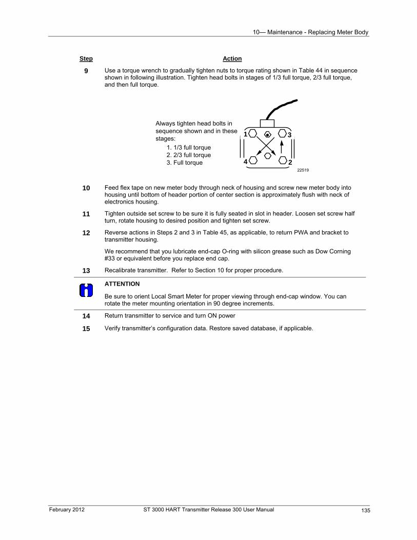
10— Maintenance - Replacing Meter Body
Step Action
9 Use a torque wrench to gradually tighten nuts to torque rating shown in Table 44 in sequence shown in following illustration. Tighten head bolts in stages of 1/3 full torque, 2/3 full torque, and then full torque.
22519
1
2
3
4
Always tighten head bolts in sequence shown and in these stages:
1. 1/3 full torque 2. 2/3 full torque 3. Full torque
10 Feed flex tape on new meter body through neck of housing and screw new meter body into housing until bottom of header portion of center section is approximately flush with neck of electronics housing.
11 Tighten outside set screw to be sure it is fully seated in slot in header. Loosen set screw half turn, rotate housing to desired position and tighten set screw.
12 Reverse actions in Steps 2 and 3 in Table 45, as applicable, to return PWA and bracket to transmitter housing.
We recommend that you lubricate end-cap O-ring with silicon grease such as Dow Corning #33 or equivalent before you replace end cap.
13 Recalibrate transmitter. Refer to Section 10 for proper procedure.
ATTENTION
Be sure to orient Local Smart Meter for proper viewing through end-cap window. You can rotate the meter mounting orientation in 90 degree increments.
14 Return transmitter to service and turn ON power
15 Verify transmitter’s configuration data. Restore saved database, if applicable.
February 2012 ST 3000 HART Transmitter Release 300 User Manual 135

-
ST 3000 HART Transmitter Release 300 User Manual February 2012 136
11— Calibration - Introduction
11— Calibration
Introduction
About this section
This section provides information about calibrating the transmitter’s analog output and measurement range. It also covers the procedure for resetting calibration to default values as a quick alternative to measurement range calibration.
This section includes these topics.
How to calibrate the transmitter’s analog output circuit using the communicator
How to perform a two-point calibration of the transmitter
How to perform a correct reset to return the transmitter calibration to its default values.
Overview
About calibration
The ST 3000 Smart Transmitter does not require recalibration at periodic intervals to maintain accuracy. If a recalibration is required, we recommend that you do a bench calibration with the transmitter removed from the process and located in a controlled environment to get the best accuracy.
Before you recalibrate the transmitter’s measurement range, you must calibrate the transmitter’s analog output signal. See Table 47 for procedure.
You can also use the communicator to reset the calibration data to default values, if they are corrupted, until the transmitter can be recalibrated. See Table 46 in this section for details.
ATTENTION
All procedures in this manual assume a transmitter poll address of 0 (zero). See page 74 for information about poll address. HART 6 transmitters have a separate menu item for switching to analog output mode.
Equipment Required
ATTENTION
Depending upon the calibration you choose, you may need any of the following test equipment to accurately calibrate the transmitter:
Digital voltmeter or milliammeter with 0.02% accuracy or better
HART hand-held communicator
Calibration-standard pressure source with a 0.02% accuracy
250 ohm resistor with 0.01% accuracy or better.
February 2012 ST 3000 HART Transmitter Release 300 User Manual 137
11— Calibration - Calibrating Analog Output Signal
ST 3000 HART Transmitter Release 300 User Manual February 2012 138
Calibrating Analog Output Signal You can calibrate the transmitter’s analog output circuit at its 0 and 100% levels by using the transmitter in its constant-current source mode. It is not necessary to remove the transmitter from service.
The procedure in Table 47 shows the steps for calibrating the output signal for a transmitter in the analog mode.
ATTENTION
You can calculate milliamperes of current from a voltage measurement by using the following equation:
dc milliamps = 1000 x voltage
resistance
Table 47 Calibrating Output Signal for Transmitter in Analog Mode
Step Action
1 Connect communicator across loop wiring and turn it on.
See Figure 30 in Section 7 for sample test equipment hookup.
ATTENTION
Be sure the accuracy of the resistor is 0.01% or better for current measurements made by voltage drop.
2 Starting from “Online” menu, choose the following menu selections:
Device setup
Diag/Service
D/A trim
You will be prompted to remove the loop from automatic control. After doing so, press OK.
When prompts appears, connect a precision milliammeter or voltmeter (0.03% accuracy or better) in loop to check readings. Press OK.
3 The following display prompts will appear:
Setting field device output to 4mA. Press OK.
Enter meter value. Key in meter value, then press ENTER.
Field device output 4.000 mA equal to reference meter? 1 Yes 2 No
If not equal, select No, press ENTER, then key in new meter value. (Returns to “Enter meter value” prompt until field device output equals reference meter.)
If equal, select Yes, press ENTER.
Go to Step 4.
11— Calibration - Calibrating Range
February 2012 ST 3000 HART Transmitter Release 300 User Manual 139
Step Action
4 The following display prompts will appear:
Setting field device output to 20mA. Press OK.
Enter meter value. Key in meter value, then press ENTER.
Field device output 20.000 mA equal to reference meter? 1 Yes 2 No
If not equal, select No, press ENTER, then key in new meter value. (Returns to “Enter meter value” prompt until field device output equals reference meter.)
If equal, select Yes, press ENTER.
Prompt notifies you that the field device will be returned to its original output.
Calibrating Range The ST 3000 Smart Transmitter has two-point calibration. This means when you calibrate two points in the range, all the points in that range adjust to that calibration.
The procedure in Table 48 and Table 49 shows the steps for calibrating a differential pressure (DP) type transmitter to a range of 0 to 200 inH2O for example purposes. This procedure assumes that the transmitter is removed from the process and located in a controlled environment.
ATTENTION
You must have a precision pressure source with an accuracy of 0.02% or better to do a range calibration. Note that we factory calibrate ST 3000 Smart Transmitters with inches of water ranges using inches of water pressure referenced to a temperature of 39.2˚F (4˚C).
Table 48 Calibrating Measurement Range – Correct LRV
Correct LRV
Step Action
1 Connect power supply and communicator to signal terminals on transmitter’s terminal block. Connect precision pressure source to high pressure side of DP type transmitter.
See Figure 43 for typical communicator, power supply, and pressure source hookup for calibration.
2 Turn on power supply and allow transmitter to stabilize its operation.
3 Turn on communicator.
4 From “Online” menu, choose the following menu selections:
Device setup
Diag/Service
Calibration
Correct Input LRV
You will be prompted to remove the loop from automatic control. After doing so, press OK.
11— Calibration - Calibrating Range
ST 3000 HART Transmitter Release 300 User Manual February 2012 140
Step Action
5 When prompted, adjust pressure source to apply pressure equal to LRV (0%), then press OK.
6 When pressure is stable, press OK. When prompted, remove pressure.
7* On the next prompt – “Please enter Calibration Date”, enter the date in the format MM/DD/YYYY (ex: 05/27/2009), then press Enter
8* On the next prompt – “Please enter current Calibration Time in 24 Hr Clock format (Hour field)”, enter the hour portion of the calibration time in the 24 Hr format HH (ex: 13), then press Enter
9* On the next prompt – “Please enter current Calibration Time (Minute field)”, enter the Minutes field MM (ex: 56), then press Enter
10* On the next prompt – “Please enter current Calibration Time (Second field)”, enter the Seconds field SS (ex: 56), then press Enter
11 When prompted, return loop to automatic control. Press Enter.
*HART 6 “Advanced Diagnostics For ST 3000 Release” only with the Universal Rev 6, Field Device Rev 5 and Software Rev 36.
For details about these parameters refer to “Diagnostics/Service - Calibration Records” under the “Advanced Diagnostics for ST 3000 Release” topic.
Table 49 Calibrating Measurement Range – Correct URV
Correct URV
Step Action
1 Connect power supply and communicator to signal terminals on transmitter’s terminal block. Connect precision pressure source to high pressure side of DP type transmitter.
See Figure 43 for typical communicator, power supply, and pressure source hookup for calibration.
2 Turn on power supply and allow transmitter to stabilize its operation.
3 Turn on communicator.
4 From “Online” menu, choose the following menu selections:
Device setup
Diag/Service
Calibration
Correct Input URV
You will be prompted to remove the loop from automatic control. After doing so, press OK.
5 When prompted, adjust pressure source to apply pressure equal to URV (100%), then press OK.
6 When pressure is stable, press OK. When prompted, remove pressure.
7* On the next prompt – “Please enter Calibration Date”, enter the date in the format MM/DD/YYYY (ex: 05/27/2009), then press Enter
8* On the next prompt – “Please enter current Calibration Time in 24 Hr Clock format (Hour field)”, enter the hour portion of the calibration time in the 24 Hr format HH (ex: 13), then press Enter
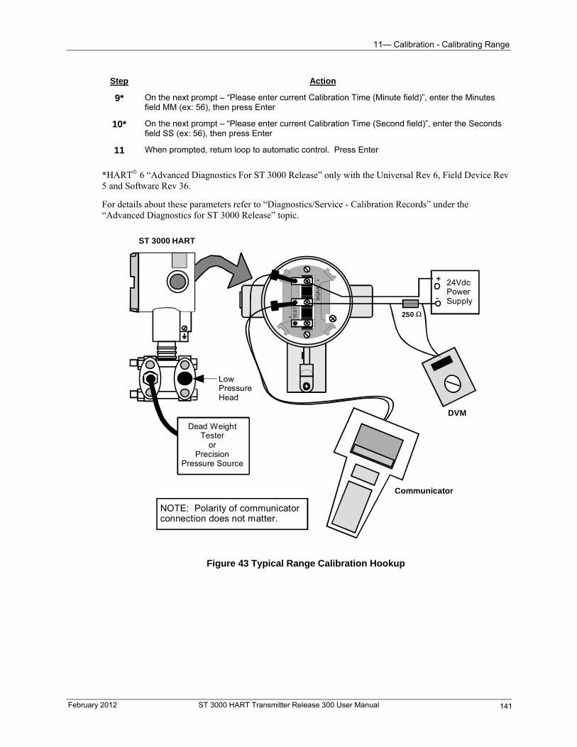
11— Calibration - Calibrating Range
Step Action
9* On the next prompt – “Please enter current Calibration Time (Minute field)”, enter the Minutes field MM (ex: 56), then press Enter
10* On the next prompt – “Please enter current Calibration Time (Second field)”, enter the Seconds field SS (ex: 56), then press Enter
11 When prompted, return loop to automatic control. Press Enter
*HART 6 “Advanced Diagnostics For ST 3000 Release” only with the Universal Rev 6, Field Device Rev 5 and Software Rev 36.
For details about these parameters refer to “Diagnostics/Service - Calibration Records” under the “Advanced Diagnostics for ST 3000 Release” topic.
- S
IGN
AL
+
+
-
TE
ST
250
24VdcPowerSupply
+
-
DVM
ST 3000 HART
LowPressureHead
Communicator
Dead WeightTester
orPrecision
Pressure Source
NOTE: Polarity of communicatorconnection does not matter.
Figure 43 Typical Range Calibration Hookup
February 2012 ST 3000 HART Transmitter Release 300 User Manual 141
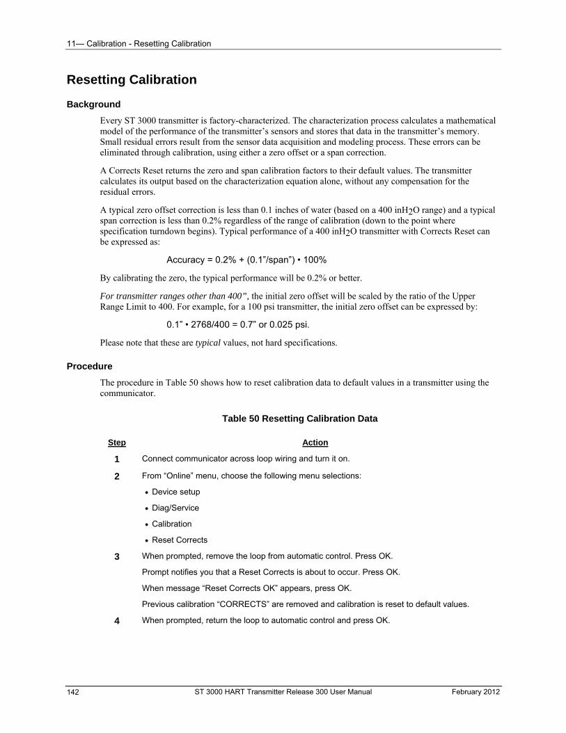
11— Calibration - Resetting Calibration
ST 3000 HART Transmitter Release 300 User Manual February 2012 142
Resetting Calibration
Background
Every ST 3000 transmitter is factory-characterized. The characterization process calculates a mathematical model of the performance of the transmitter’s sensors and stores that data in the transmitter’s memory. Small residual errors result from the sensor data acquisition and modeling process. These errors can be eliminated through calibration, using either a zero offset or a span correction.
A Corrects Reset returns the zero and span calibration factors to their default values. The transmitter calculates its output based on the characterization equation alone, without any compensation for the residual errors.
A typical zero offset correction is less than 0.1 inches of water (based on a 400 inH2O range) and a typical span correction is less than 0.2% regardless of the range of calibration (down to the point where specification turndown begins). Typical performance of a 400 inH2O transmitter with Corrects Reset can be expressed as:
Accuracy = 0.2% + (0.1”/span”) • 100%
By calibrating the zero, the typical performance will be 0.2% or better.
For transmitter ranges other than 400”, the initial zero offset will be scaled by the ratio of the Upper Range Limit to 400. For example, for a 100 psi transmitter, the initial zero offset can be expressed by:
0.1” • 2768/400 = 0.7” or 0.025 psi.
Please note that these are typical values, not hard specifications.
Procedure
The procedure in Table 50 shows how to reset calibration data to default values in a transmitter using the communicator.
Table 50 Resetting Calibration Data
Step Action
1 Connect communicator across loop wiring and turn it on.
2 From “Online” menu, choose the following menu selections:
Device setup
Diag/Service
Calibration
Reset Corrects
3 When prompted, remove the loop from automatic control. Press OK.
Prompt notifies you that a Reset Corrects is about to occur. Press OK.
When message “Reset Corrects OK” appears, press OK.
Previous calibration “CORRECTS” are removed and calibration is reset to default values.
4 When prompted, return the loop to automatic control and press OK.
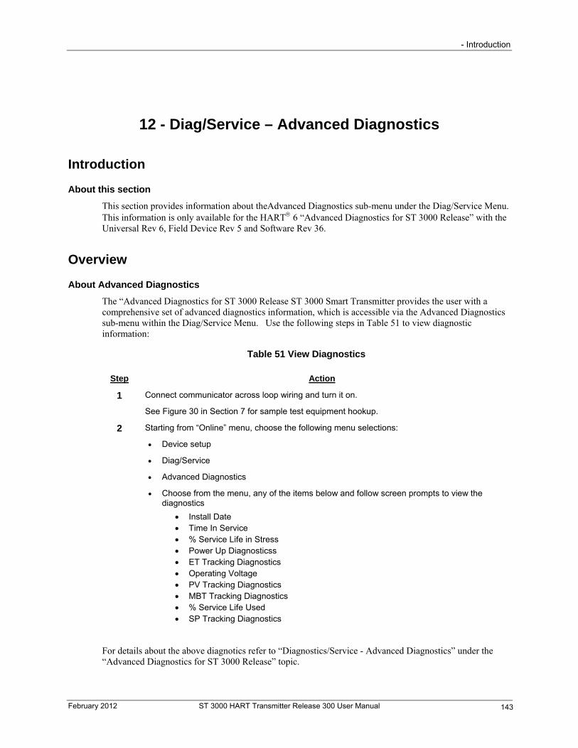
- Introduction
February 2012 ST 3000 HART Transmitter Release 300 User Manual 143
12 - Diag/Service – Advanced Diagnostics
Introduction
About this section
This section provides information about theAdvanced Diagnostics sub-menu under the Diag/Service Menu. This information is only available for the HART 6 “Advanced Diagnostics for ST 3000 Release” with the Universal Rev 6, Field Device Rev 5 and Software Rev 36.
Overview
About Advanced Diagnostics
The “Advanced Diagnostics for ST 3000 Release ST 3000 Smart Transmitter provides the user with a comprehensive set of advanced diagnostics information, which is accessible via the Advanced Diagnostics sub-menu within the Diag/Service Menu. Use the following steps in Table 51 to view diagnostic information:
Table 51 View Diagnostics
Step Action
1 Connect communicator across loop wiring and turn it on.
See Figure 30 in Section 7 for sample test equipment hookup.
2 Starting from “Online” menu, choose the following menu selections:
Device setup
Diag/Service
Advanced Diagnostics
Choose from the menu, any of the items below and follow screen prompts to view the diagnostics
Install Date Time In Service % Service Life in Stress Power Up Diagnosticss ET Tracking Diagnostics Operating Voltage PV Tracking Diagnostics MBT Tracking Diagnostics % Service Life Used SP Tracking Diagnostics
For details about the above diagnotics refer to “Diagnostics/Service - Advanced Diagnostics” under the “Advanced Diagnostics for ST 3000 Release” topic.

12 - Diag/Service – Advanced Diagnostics - Overview
ST 3000 HART Transmitter Release 300 User Manual February 2012 144
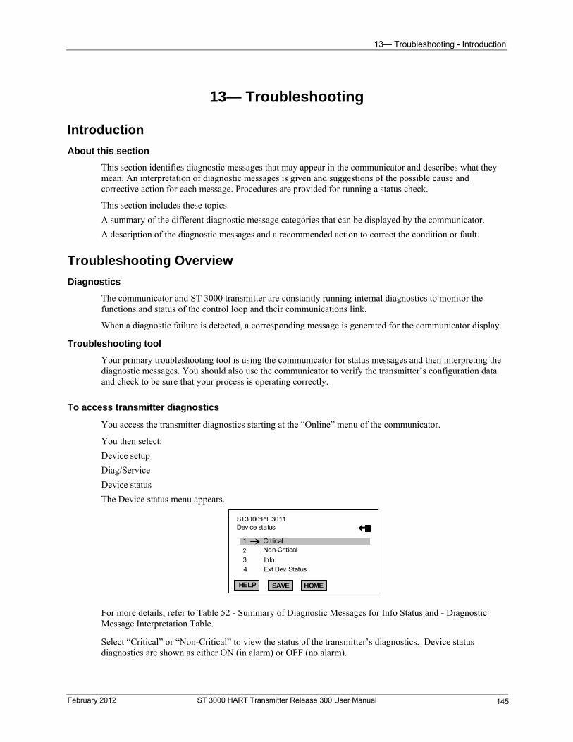
13— Troubleshooting - Introduction
13— Troubleshooting
Introduction
About this section
This section identifies diagnostic messages that may appear in the communicator and describes what they mean. An interpretation of diagnostic messages is given and suggestions of the possible cause and corrective action for each message. Procedures are provided for running a status check.
This section includes these topics.
A summary of the different diagnostic message categories that can be displayed by the communicator.
A description of the diagnostic messages and a recommended action to correct the condition or fault.
Troubleshooting Overview
Diagnostics
The communicator and ST 3000 transmitter are constantly running internal diagnostics to monitor the functions and status of the control loop and their communications link.
When a diagnostic failure is detected, a corresponding message is generated for the communicator display.
Troubleshooting tool
Your primary troubleshooting tool is using the communicator for status messages and then interpreting the diagnostic messages. You should also use the communicator to verify the transmitter’s configuration data and check to be sure that your process is operating correctly.
To access transmitter diagnostics
You access the transmitter diagnostics starting at the “Online” menu of the communicator.
You then select:
Device setup
Diag/Service
Device status
The Device status menu appears.
2 ST3000:PT 3011 Device status
1
2
CriticalNon-Critical
HELP SAVE HOME
3
4
Info
Ext Dev Status
For more details, refer to Table 52 - Summary of Diagnostic Messages for Info Status and - Diagnostic Message Interpretation Table.
Select “Critical” or “Non-Critical” to view the status of the transmitter’s diagnostics. Device status diagnostics are shown as either ON (in alarm) or OFF (no alarm).
February 2012 ST 3000 HART Transmitter Release 300 User Manual 145
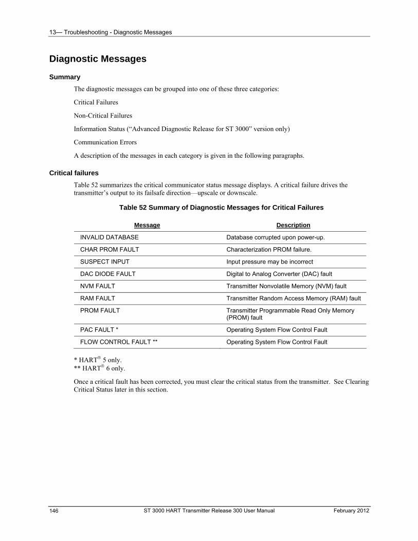
13— Troubleshooting - Diagnostic Messages
Diagnostic Messages
Summary
The diagnostic messages can be grouped into one of these three categories:
Critical Failures
Non-Critical Failures
Information Status (“Advanced Diagnostic Release for ST 3000” version only)
Communication Errors
A description of the messages in each category is given in the following paragraphs.
Critical failures
Table 52 summarizes the critical communicator status message displays. A critical failure drives the transmitter’s output to its failsafe direction—upscale or downscale.
Table 52 Summary of Diagnostic Messages for Critical Failures
Message Description
INVALID DATABASE Database corrupted upon power-up.
CHAR PROM FAULT Characterization PROM failure.
SUSPECT INPUT Input pressure may be incorrect
DAC DIODE FAULT Digital to Analog Converter (DAC) fault
NVM FAULT Transmitter Nonvolatile Memory (NVM) fault
RAM FAULT Transmitter Random Access Memory (RAM) fault
PROM FAULT Transmitter Programmable Read Only Memory (PROM) fault
PAC FAULT * Operating System Flow Control Fault
FLOW CONTROL FAULT ** Operating System Flow Control Fault
* HART 5 only. ** HART 6 only.
Once a critical fault has been corrected, you must clear the critical status from the transmitter. See Clearing Critical Status later in this section.
ST 3000 HART Transmitter Release 300 User Manual February 2012 146
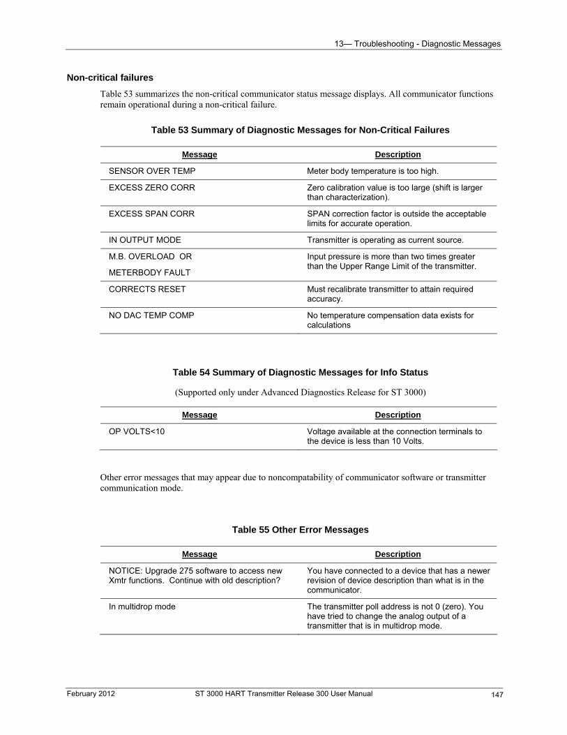
13— Troubleshooting - Diagnostic Messages
Non-critical failures
Table 53 summarizes the non-critical communicator status message displays. All communicator functions remain operational during a non-critical failure.
Table 53 Summary of Diagnostic Messages for Non-Critical Failures
Message Description
SENSOR OVER TEMP Meter body temperature is too high.
EXCESS ZERO CORR Zero calibration value is too large (shift is larger than characterization).
EXCESS SPAN CORR SPAN correction factor is outside the acceptable limits for accurate operation.
IN OUTPUT MODE Transmitter is operating as current source.
M.B. OVERLOAD OR
METERBODY FAULT
Input pressure is more than two times greater than the Upper Range Limit of the transmitter.
CORRECTS RESET Must recalibrate transmitter to attain required accuracy.
NO DAC TEMP COMP No temperature compensation data exists for calculations
Table 54 Summary of Diagnostic Messages for Info Status
(Supported only under Advanced Diagnostics Release for ST 3000)
Message Description
OP VOLTS<10 Voltage available at the connection terminals to the device is less than 10 Volts.
Other error messages that may appear due to noncompatability of communicator software or transmitter communication mode.
Table 55 Other Error Messages
Message Description
NOTICE: Upgrade 275 software to access new Xmtr functions. Continue with old description?
You have connected to a device that has a newer revision of device description than what is in the communicator.
In multidrop mode The transmitter poll address is not 0 (zero). You have tried to change the analog output of a transmitter that is in multidrop mode.
February 2012 ST 3000 HART Transmitter Release 300 User Manual 147
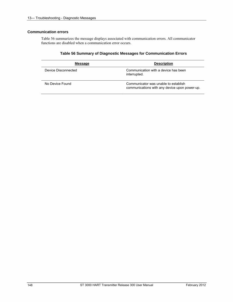
13— Troubleshooting - Diagnostic Messages
Communication errors
Table 56 summarizes the message displays associated with communication errors. All communicator functions are disabled when a communication error occurs.
Table 56 Summary of Diagnostic Messages for Communication Errors
Message Description
Device Disconnected
Communication with a device has been interrupted.
No Device Found
Communicator was unable to establish communications with any device upon power-up.
ST 3000 HART Transmitter Release 300 User Manual February 2012 148
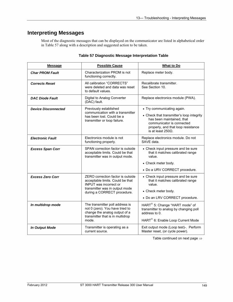
13— Troubleshooting - Interpreting Messages
February 2012 ST 3000 HART Transmitter Release 300 User Manual 149
Interpreting Messages Most of the diagnostic messages that can be displayed on the communicator are listed in alphabetical order in Table 57 along with a description and suggested action to be taken.
Table 57 Diagnostic Message Interpretation Table
Message Possible Cause What to Do
Char PROM Fault Characterization PROM is not functioning correctly.
Replace meter body.
Corrects Reset All calibration “CORRECTS” were deleted and data was reset to default values.
Recalibrate transmitter. See Section 10.
DAC Diode Fault Digital to Analog Converter (DAC) fault.
Replace electronics module (PWA).
Device Disconnected Previously established communication with a transmitter has been lost. Could be a transmitter or loop failure.
Try communicating again.
Check that transmitter’s loop integrity has been maintained, that communicator is connected properly, and that loop resistance is at least 250Ω.
Electronic Fault Electronics module is not functioning properly.
Replace electronics module. Do not SAVE data.
Excess Span Corr SPAN correction factor is outside acceptable limits. Could be that transmitter was in output mode.
Check input pressure and be sure that it matches calibrated range value.
Check meter body.
Do a URV CORRECT procedure.
Excess Zero Corr ZERO correction factor is outside acceptable limits. Could be that INPUT was incorrect or transmitter was in output mode during a CORRECT procedure.
Check input pressure and be sure that it matches calibrated range value.
Check meter body.
Do an LRV CORRECT procedure.
In multidrop mode The transmitter poll address is not 0 (zero). You have tried to change the analog output of a transmitter that is in multidrop mode.
HART 5: Change “HART mode” of transmitter to analog by changing poll address to 0.
HART 6: Enable Loop Current Mode
In Output Mode Transmitter is operating as a current source.
Exit output mode (Loop test)-. Perform Master reset, (or cycle power).
Table continued on next page
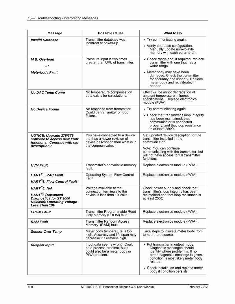
13— Troubleshooting - Interpreting Messages
ST 3000 HART Transmitter Release 300 User Manual February 2012 150
Message Possible Cause What to Do
Invalid Database Transmitter database was incorrect at power-up.
Try communicating again.
Verify database configuration, Manually update non-volatile memory with each parameter.
M.B. Overload
OR
Meterbody Fault
Pressure input is two times greater than URL of transmitter.
Check range and, if required, replace transmitter with one that has a wider range.
Meter body may have been damaged. Check the transmitter for accuracy and linearity. Replace meter body and recalibrate, if needed.
No DAC Temp Comp No temperature compensation data exists for calculations.
Effect will be minor degradation of ambient temperature influence specifications. Replace electronics module (PWA).
No Device Found No response from transmitter. Could be transmitter or loop failure.
Try communicating again.
Check that transmitter’s loop integrity has been maintained, that communicator is connected properly, and that loop resistance is at least 250Ω.
NOTICE: Upgrade 275/375 software to access new Xmtr functions. Continue with old description?
You have connected to a device that has a newer revision of device description than what is in the communicator.
Get updated device description for the transmitter installed in the communicator.
Note: You can continue communicating with the transmitter, but will not have access to full transmitter functions.
NVM Fault Transmitter’s nonvolatile memory fault.
Replace electronics module (PWA).
HART5: PAC Fault
HART6: Flow Control Fault
Operating System Flow Control Fault
Replace electronics module (PWA)
HART5: N/A
HART6 (Advanced Diagnostics for ST 3000 Release): Operating Voltage Less Than 10V
Voltage available at the connection terminals to the device is less than 10 Volts.
Check power supply and check that transmitter’s loop integrity has been maintained and that loop resistance is at least 250Ω.
PROM Fault Transmitter Programmable Read Only Memory (PROM) fault
Replace electronics module (PWA).
RAM Fault Transmitter Random Access Memory (RAM) fault.
Replace electronics module (PWA).
Sensor Over Temp Meter body temperature is too high. Accuracy and life span may decrease if it remains high.
Take steps to insulate meter body from temperature source.
Suspect Input Input data seems wrong. Could be a process problem, but it could also be a meter body or PWA problem.
Put transmitter in output mode. Diagnostic messages should identify where problem is. If no other diagnostic message is given, condition is most likely meter body related.
Check installation and replace meter body if condition persists.
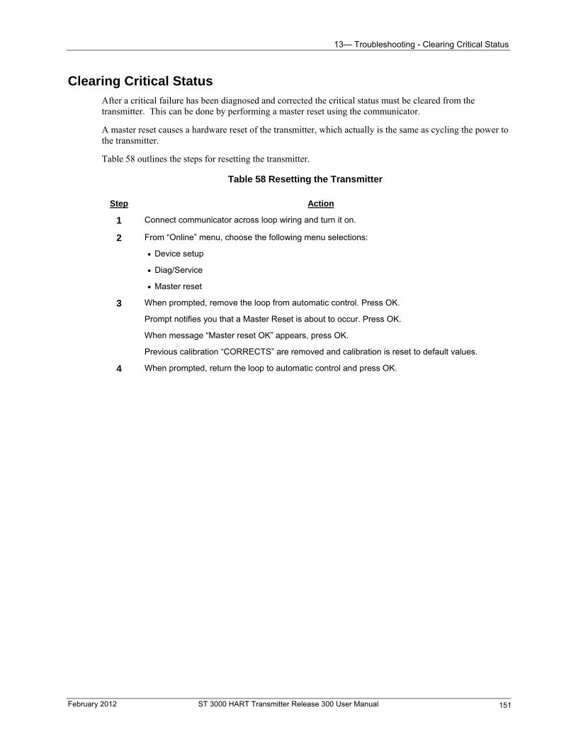
13— Troubleshooting - Clearing Critical Status
February 2012 ST 3000 HART Transmitter Release 300 User Manual 151
Clearing Critical Status After a critical failure has been diagnosed and corrected the critical status must be cleared from the transmitter. This can be done by performing a master reset using the communicator.
A master reset causes a hardware reset of the transmitter, which actually is the same as cycling the power to the transmitter.
Table 58 outlines the steps for resetting the transmitter.
Table 58 Resetting the Transmitter
Step Action
1 Connect communicator across loop wiring and turn it on.
2 From “Online” menu, choose the following menu selections:
Device setup
Diag/Service
Master reset
3 When prompted, remove the loop from automatic control. Press OK.
Prompt notifies you that a Master Reset is about to occur. Press OK.
When message “Master reset OK” appears, press OK.
Previous calibration “CORRECTS” are removed and calibration is reset to default values.
4 When prompted, return the loop to automatic control and press OK.
14— Parts List - Replacement Parts
14— Parts List
Replacement Parts
About this section
All individually saleable parts for the various transmitter models are listed in this section. Some parts are illustrated for identification. Parts are identified and listed in the corresponding tables as follows:
All individually saleable parts are indicated in each figure by key number callout. For example: 1, 2, 3, and so on.
All parts that are supplied in kits are indicated in each figure by key number callout with the letter “K” prefix. For example: K1, K2, K3, and so on.
Parts denoted with a “†” are recommended spares. See Table 70 for summary list of recommended spare parts.
Figure 40 shows major parts for a given model with reference to parts list figures.
ST 3000 HART Transmitter Release 300 User Manual February 2012 152
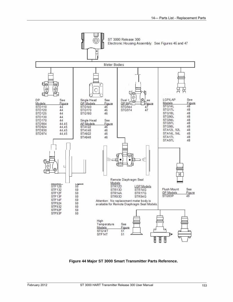
14— Parts List - Replacement Parts
Figure 44 Major ST 3000 Smart Transmitter Parts Reference.
February 2012 ST 3000 HART Transmitter Release 300 User Manual 153
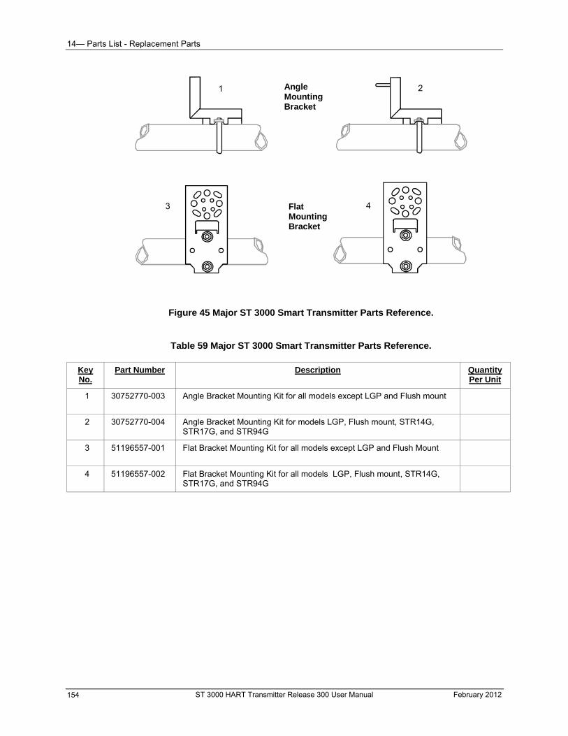
14— Parts List - Replacement Parts
2AngleMountingBracket
FlatMountingBracket
43
1
Figure 45 Major ST 3000 Smart Transmitter Parts Reference.
Table 59 Major ST 3000 Smart Transmitter Parts Reference.
Key No.
Part Number Description Quantity Per Unit
1 30752770-003
Angle Bracket Mounting Kit for all models except LGP and Flush mount
2 30752770-004
Angle Bracket Mounting Kit for models LGP, Flush mount, STR14G, STR17G, and STR94G
3 51196557-001 Flat Bracket Mounting Kit for all models except LGP and Flush Mount
4 51196557-002 Flat Bracket Mounting Kit for all models LGP, Flush mount, STR14G, STR17G, and STR94G
ST 3000 HART Transmitter Release 300 User Manual February 2012 154
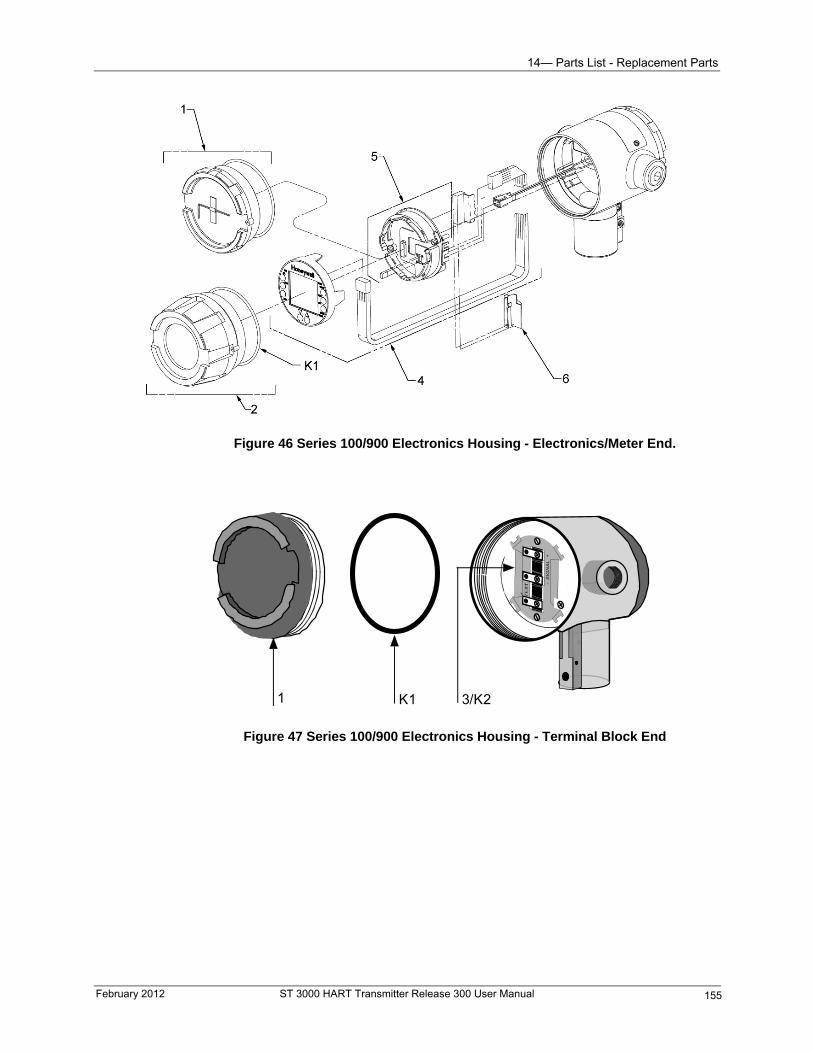
14— Parts List - Replacement Parts
Figure 46 Series 100/900 Electronics Housing - Electronics/Meter End.
K11 3/K2
Figure 47 Series 100/900 Electronics Housing - Terminal Block End
February 2012 ST 3000 HART Transmitter Release 300 User Manual 155
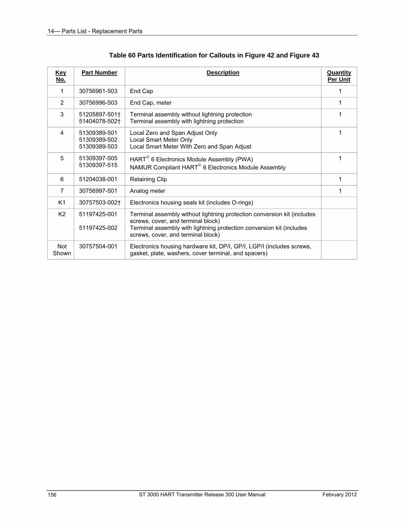
14— Parts List - Replacement Parts
Table 60 Parts Identification for Callouts in Figure 42 and Figure 43
Part Number Description Quantity Per Unit
Key No.
1 30756961-503 End Cap 1
2 30756996-503 End Cap, meter 1
3 51205897-501† 51404078-502†
Terminal assembly without lightning protection Terminal assembly with lightning protection
1
4 51309389-501 51309389-502 51309389-503
Local Zero and Span Adjust Only Local Smart Meter Only Local Smart Meter With Zero and Span Adjust
1
5 51309397-505 51309397-515
HART 6 Electronics Module Assembly (PWA) NAMUR Compliant HART 6 Electronics Module Assembly
1
6 51204038-001 Retaining Clip 1
7 30756997-501 Analog meter 1
K1 30757503-002† Electronics housing seals kit (includes O-rings)
K2 51197425-001 51197425-002
Terminal assembly without lightning protection conversion kit (includes screws, cover, and terminal block) Terminal assembly with lightning protection conversion kit (includes screws, cover, and terminal block)
Not Shown
30757504-001 Electronics housing hardware kit, DP/I, GP/I, LGP/I (includes screws, gasket, plate, washers, cover terminal, and spacers)
ST 3000 HART Transmitter Release 300 User Manual February 2012 156
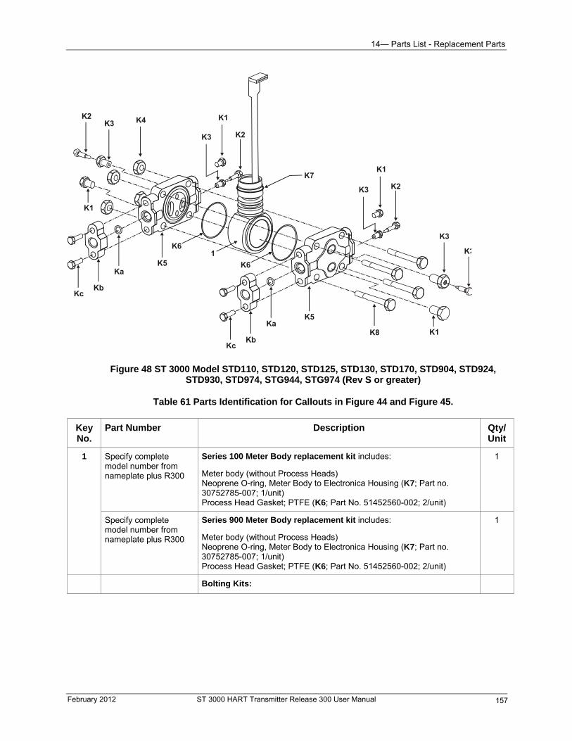
14— Parts List - Replacement Parts
Figure 48 ST 3000 Model STD110, STD120, STD125, STD130, STD170, STD904, STD924, STD930, STD974, STG944, STG974 (Rev S or greater)
Table 61 Parts Identification for Callouts in Figure 44 and Figure 45.
Key No.
Part Number Description Qty/ Unit
1 Specify complete model number from nameplate plus R300
Series 100 Meter Body replacement kit includes:
Meter body (without Process Heads) Neoprene O-ring, Meter Body to Electronica Housing (K7; Part no. 30752785-007; 1/unit) Process Head Gasket; PTFE (K6; Part No. 51452560-002; 2/unit)
1
Specify complete model number from nameplate plus R300
Series 900 Meter Body replacement kit includes:
Meter body (without Process Heads) Neoprene O-ring, Meter Body to Electronica Housing (K7; Part no. 30752785-007; 1/unit) Process Head Gasket; PTFE (K6; Part No. 51452560-002; 2/unit)
1
Bolting Kits:
February 2012 ST 3000 HART Transmitter Release 300 User Manual 157
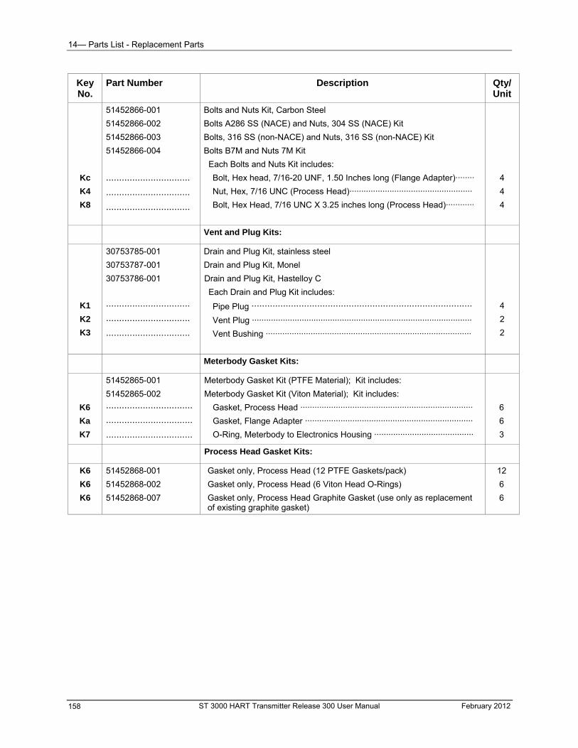
14— Parts List - Replacement Parts
Key No.
Part Number Description Qty/ Unit
Kc
K4
K8
51452866-001
51452866-002
51452866-003
51452866-004
································
································
································
Bolts and Nuts Kit, Carbon Steel
Bolts A286 SS (NACE) and Nuts, 304 SS (NACE) Kit
Bolts, 316 SS (non-NACE) and Nuts, 316 SS (non-NACE) Kit
Bolts B7M and Nuts 7M Kit
Each Bolts and Nuts Kit includes:
Bolt, Hex head, 7/16-20 UNF, 1.50 Inches long (Flange Adapter)········
Nut, Hex, 7/16 UNC (Process Head)····················································
Bolt, Hex Head, 7/16 UNC X 3.25 inches long (Process Head)············
4
4
4
Vent and Plug Kits:
K1
K2
K3
30753785-001
30753787-001
30753786-001
································
································
································
Drain and Plug Kit, stainless steel
Drain and Plug Kit, Monel
Drain and Plug Kit, Hastelloy C
Each Drain and Plug Kit includes:
Pipe Plug ····················································································
Vent Plug ·····························································································
Vent Bushing ·······················································································
4
2
2
Meterbody Gasket Kits:
K6
Ka
K7
51452865-001
51452865-002
·································
·································
·································
Meterbody Gasket Kit (PTFE Material); Kit includes:
Meterbody Gasket Kit (Viton Material); Kit includes:
Gasket, Process Head ·········································································
Gasket, Flange Adapter ·······································································
O-Ring, Meterbody to Electronics Housing ··········································
6
6
3
Process Head Gasket Kits:
K6
K6
K6
51452868-001
51452868-002
51452868-007
Gasket only, Process Head (12 PTFE Gaskets/pack)
Gasket only, Process Head (6 Viton Head O-Rings)
Gasket only, Process Head Graphite Gasket (use only as replacement of existing graphite gasket)
12
6
6
ST 3000 HART Transmitter Release 300 User Manual February 2012 158
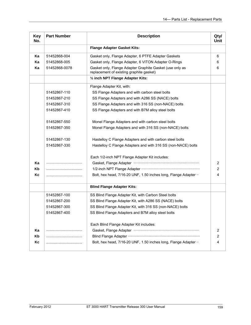
14— Parts List - Replacement Parts
Key No.
Part Number Description Qty/ Unit
Flange Adapter Gasket Kits:
Ka
Ka
Ka
51452868-004
51452868-005
51452868-0078
Gasket only, Flange Adapter, 6 PTFE Adapter Gaskets
Gasket only, Flange Adapter, 6 VITON Adapter O-Rings
Gasket only, Flange Adapter Graphite Gasket (use only as replacement of existing graphite gasket)
6
6
6
½ inch NPT Flange Adapter Kits:
Ka
Kb
Kc
51452867-110
51452867-210
51452867-310
51452867-410
51452867-550
51452867-350
51452867-130
51452867-330
···································
···································
···································
Flange Adapter Kit, with:
SS Flange Adapters and with carbon steel bolts
SS Flange Adapters and with A286 SS (NACE) bolts
SS Flange Adapters and with 316 SS (non-NACE) bolts
SS Flange Adapters and with B7M alloy steel bolts
Monel Flange Adapters and with carbon steel bolts
Monel Flange Adapters and with 316 SS (non-NACE) bolts
Hastelloy C Flange Adapters and with carbon steel bolts
Hastelloy C Flange Adapters and with 316 SS (non-NACE) bolts
Each 1/2-inch NPT Flange Adapter Kit includes:
Gasket, Flange Adapter ································································
1/2-inch NPT Flange Adapter ·························································
Bolt, hex head, 7/16-20 UNF, 1.50 inches long, Flange Adapter ··
2
2
4
Blind Flange Adapter Kits:
Ka
Kb
Kc
51452867-100
51452867-200
51452867-300
51452867-400
···································
···································
···································
SS Blind Flange Adapter Kit, with Carbon Steel bolts
SS Blind Flange Adapter Kit, with A286 SS (NACE) bolts
SS Blind Flange Adapter Kit, with 316 SS (non-NACE) bolts
SS Blind Flange Adapters and B7M alloy steel bolts
Each Blind Flange Adapter Kit includes:
2
2
Gasket, Flange Adapter ································································
Blind Flange Adapter ······································································
Bolt, hex head, 7/16-20 UNF, 1.50 inches long, Flange Adapter ·· 4
February 2012 ST 3000 HART Transmitter Release 300 User Manual 159
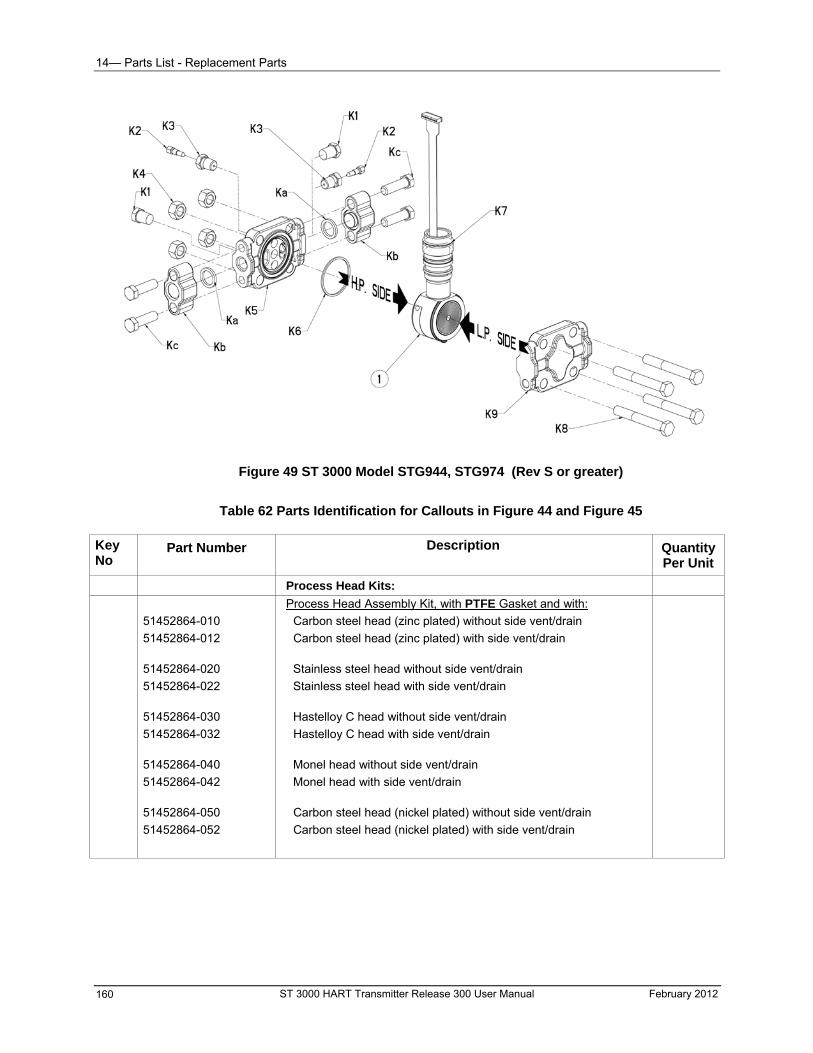
14— Parts List - Replacement Parts
Figure 49 ST 3000 Model STG944, STG974 (Rev S or greater)
Table 62 Parts Identification for Callouts in Figure 44 and Figure 45 Key No
Part Number Description Quantity Per Unit
Process Head Kits:
51452864-010
51452864-012
51452864-020
51452864-022
51452864-030
51452864-032
51452864-040
51452864-042
51452864-050
51452864-052
Process Head Assembly Kit, with PTFE Gasket and with:
Carbon steel head (zinc plated) without side vent/drain
Carbon steel head (zinc plated) with side vent/drain
Stainless steel head without side vent/drain
Stainless steel head with side vent/drain
Hastelloy C head without side vent/drain
Hastelloy C head with side vent/drain
Monel head without side vent/drain
Monel head with side vent/drain
Carbon steel head (nickel plated) without side vent/drain
Carbon steel head (nickel plated) with side vent/drain
ST 3000 HART Transmitter Release 300 User Manual February 2012 160
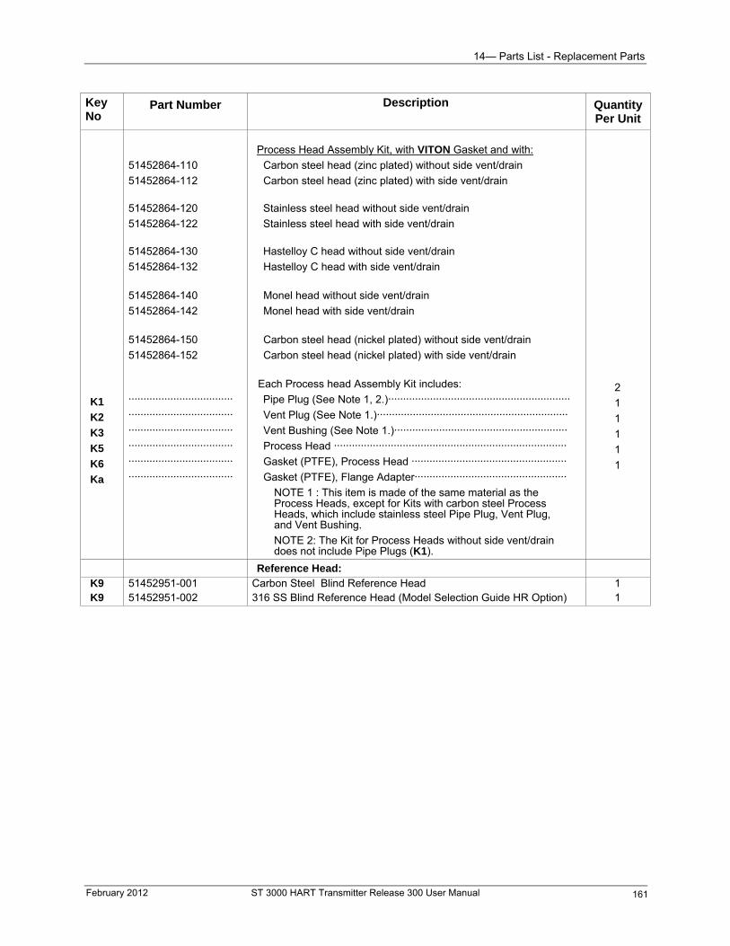
14— Parts List - Replacement Parts
Key No
Part Number Description Quantity Per Unit
K1
K2
K3
K5
K6
Ka
51452864-110
51452864-112
51452864-120
51452864-122
51452864-130
51452864-132
51452864-140
51452864-142
51452864-150
51452864-152
··································· ··································· ··································· ··································· ··································· ···································
Process Head Assembly Kit, with VITON Gasket and with:
Carbon steel head (zinc plated) without side vent/drain
Carbon steel head (zinc plated) with side vent/drain
Stainless steel head without side vent/drain
Stainless steel head with side vent/drain
Hastelloy C head without side vent/drain
Hastelloy C head with side vent/drain
Monel head without side vent/drain
Monel head with side vent/drain
Carbon steel head (nickel plated) without side vent/drain
Carbon steel head (nickel plated) with side vent/drain
Each Process head Assembly Kit includes:
Pipe Plug (See Note 1, 2.)····························································· Vent Plug (See Note 1.)································································ Vent Bushing (See Note 1.)·························································· Process Head ·············································································· Gasket (PTFE), Process Head ···················································· Gasket (PTFE), Flange Adapter···················································
NOTE 1 : This item is made of the same material as the Process Heads, except for Kits with carbon steel Process Heads, which include stainless steel Pipe Plug, Vent Plug, and Vent Bushing. NOTE 2: The Kit for Process Heads without side vent/drain does not include Pipe Plugs (K1).
2
1
1
1
1
1
Reference Head: K9 51452951-001 Carbon Steel Blind Reference Head K9 51452951-002 316 SS Blind Reference Head (Model Selection Guide HR Option)
1 1
February 2012 ST 3000 HART Transmitter Release 300 User Manual 161
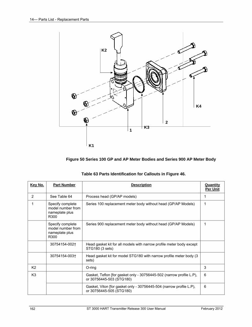
14— Parts List - Replacement Parts
K1
1
K2
K32
K4
Figure 50 Series 100 GP and AP Meter Bodies and Series 900 AP Meter Body
Table 63 Parts Identification for Callouts in Figure 46. Key No. Part Number Description Quantity
Per Unit
2 See Table 64 Process head (GP/AP models) 1
1 Specify complete model number from nameplate plus R300
Series 100 replacement meter body without head (GP/AP Models) 1
Specify complete model number from nameplate plus R300
Series 900 replacement meter body without head (GP/AP Models) 1
30754154-002† Head gasket kit for all models with narrow profile meter body except STG180 (3 sets)
30754154-003† Head gasket kit for model STG180 with narrow profile meter body (3 sets)
K2 O-ring 3
K3 Gasket, Teflon [for gasket only - 30756445-502 (narrow profile L.P), or 30756445-503 (STG180)
6
Gasket, Viton [for gasket only - 30756445-504 (narrow profile L.P), or 30756445-505 (STG180)
6
ST 3000 HART Transmitter Release 300 User Manual February 2012 162
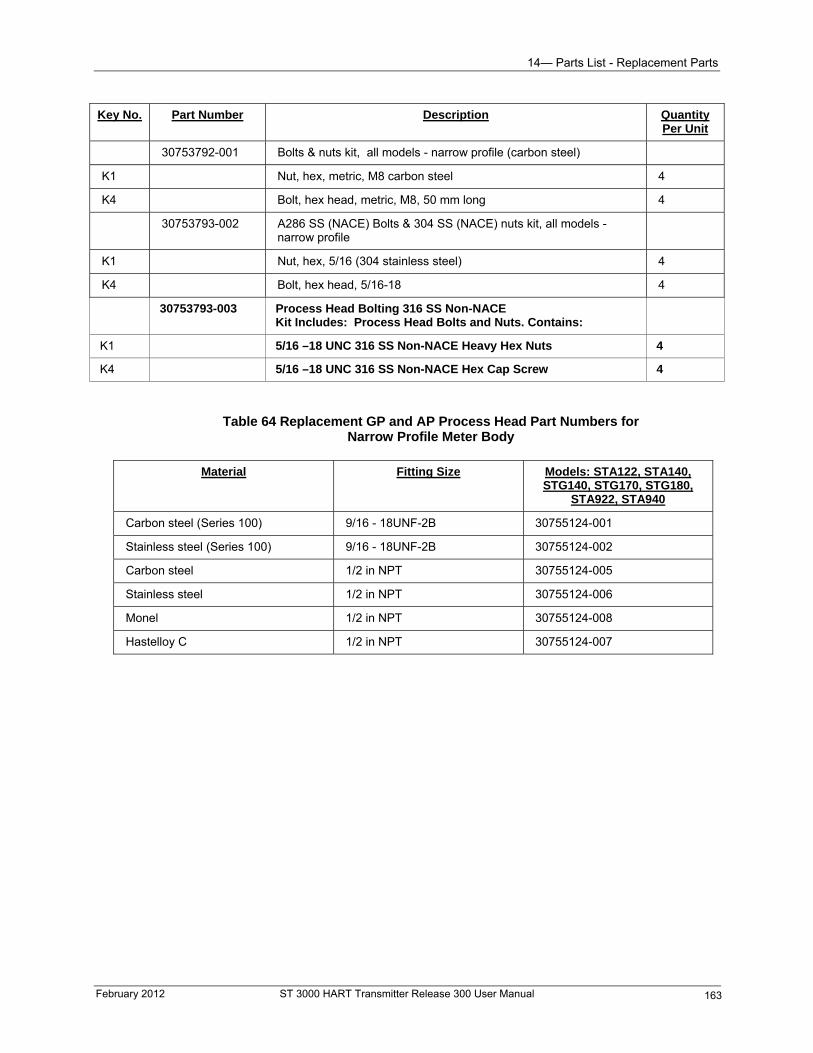
14— Parts List - Replacement Parts
Key No. Part Number Description Quantity Per Unit
30753792-001 Bolts & nuts kit, all models - narrow profile (carbon steel)
K1 Nut, hex, metric, M8 carbon steel 4
K4 Bolt, hex head, metric, M8, 50 mm long 4
30753793-002 A286 SS (NACE) Bolts & 304 SS (NACE) nuts kit, all models - narrow profile
K1 Nut, hex, 5/16 (304 stainless steel) 4
K4 Bolt, hex head, 5/16-18 4
30753793-003 Process Head Bolting 316 SS Non-NACE Kit Includes: Process Head Bolts and Nuts. Contains:
K1 5/16 –18 UNC 316 SS Non-NACE Heavy Hex Nuts 4
K4 5/16 –18 UNC 316 SS Non-NACE Hex Cap Screw 4
Table 64 Replacement GP and AP Process Head Part Numbers for Narrow Profile Meter Body
Material Fitting Size Models: STA122, STA140,
STG140, STG170, STG180, STA922, STA940
Carbon steel (Series 100) 9/16 - 18UNF-2B 30755124-001
Stainless steel (Series 100) 9/16 - 18UNF-2B 30755124-002
Carbon steel 1/2 in NPT 30755124-005
Stainless steel 1/2 in NPT 30755124-006
Monel 1/2 in NPT 30755124-008
Hastelloy C 1/2 in NPT 30755124-007
February 2012 ST 3000 HART Transmitter Release 300 User Manual 163
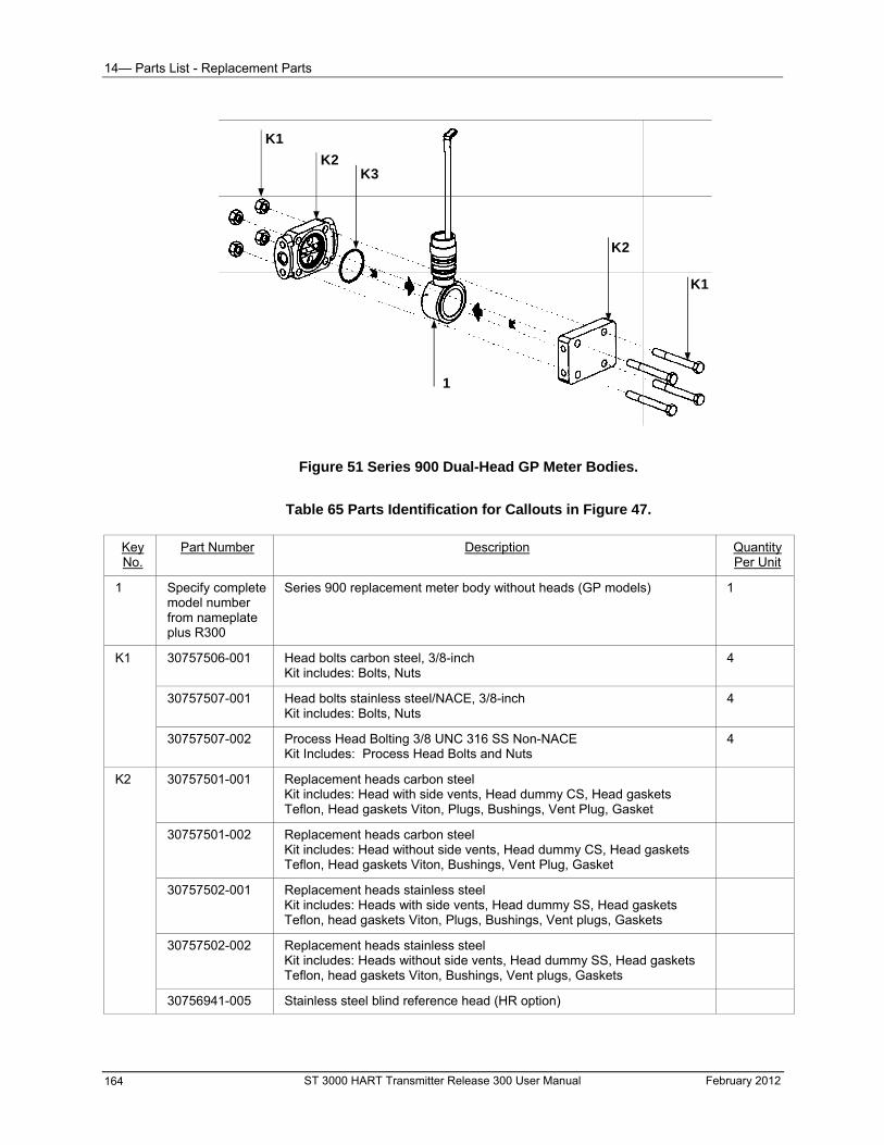
14— Parts List - Replacement Parts
K1
K2K3
1
K2
K1
Figure 51 Series 900 Dual-Head GP Meter Bodies.
Table 65 Parts Identification for Callouts in Figure 47.
Key No.
Part Number Description Quantity Per Unit
1 Specify complete model number from nameplate plus R300
Series 900 replacement meter body without heads (GP models) 1
K1 30757506-001 Head bolts carbon steel, 3/8-inch Kit includes: Bolts, Nuts
4
30757507-001 Head bolts stainless steel/NACE, 3/8-inch Kit includes: Bolts, Nuts
4
30757507-002 Process Head Bolting 3/8 UNC 316 SS Non-NACE Kit Includes: Process Head Bolts and Nuts
4
K2 30757501-001 Replacement heads carbon steel Kit includes: Head with side vents, Head dummy CS, Head gaskets Teflon, Head gaskets Viton, Plugs, Bushings, Vent Plug, Gasket
30757501-002 Replacement heads carbon steel Kit includes: Head without side vents, Head dummy CS, Head gaskets Teflon, Head gaskets Viton, Bushings, Vent Plug, Gasket
30757502-001 Replacement heads stainless steel Kit includes: Heads with side vents, Head dummy SS, Head gaskets Teflon, head gaskets Viton, Plugs, Bushings, Vent plugs, Gaskets
30757502-002 Replacement heads stainless steel Kit includes: Heads without side vents, Head dummy SS, Head gaskets Teflon, head gaskets Viton, Bushings, Vent plugs, Gaskets
30756941-005 Stainless steel blind reference head (HR option)
ST 3000 HART Transmitter Release 300 User Manual February 2012 164
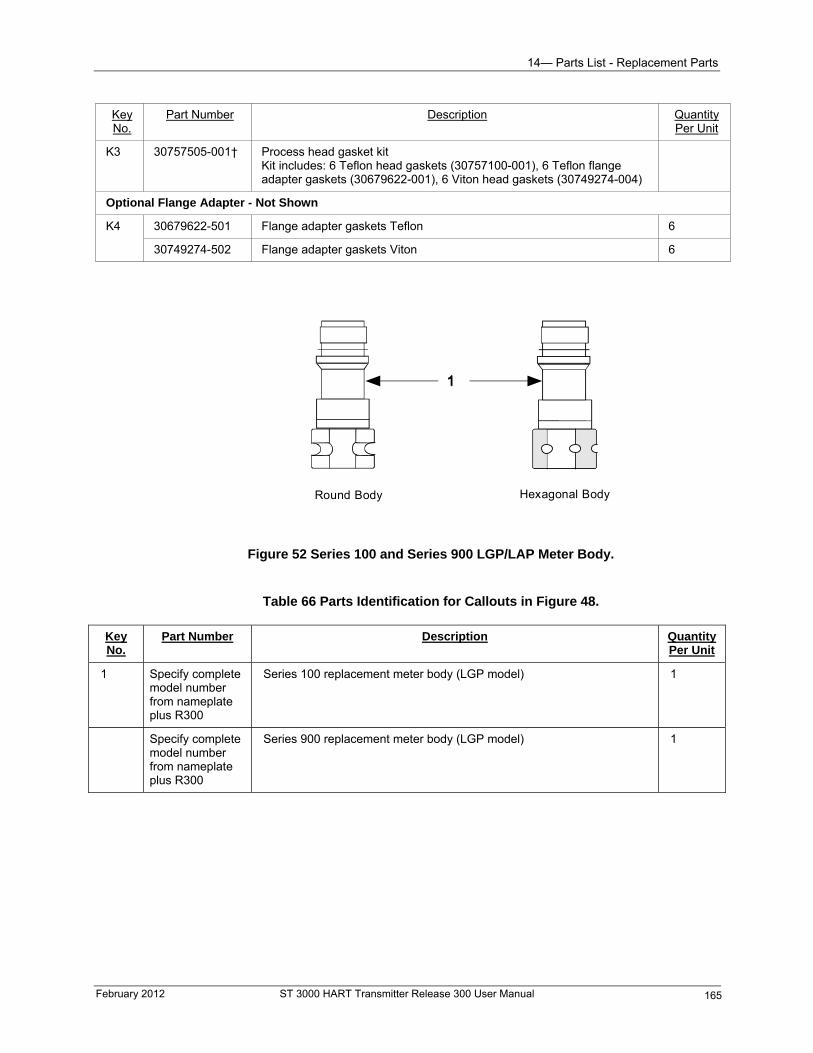
14— Parts List - Replacement Parts
Key No.
Part Number Description Quantity Per Unit
K3 30757505-001† Process head gasket kit Kit includes: 6 Teflon head gaskets (30757100-001), 6 Teflon flange adapter gaskets (30679622-001), 6 Viton head gaskets (30749274-004)
Optional Flange Adapter - Not Shown
K4 30679622-501 Flange adapter gaskets Teflon 6
30749274-502 Flange adapter gaskets Viton 6
Hexagonal BodyRound Body
Figure 52 Series 100 and Series 900 LGP/LAP Meter Body.
Table 66 Parts Identification for Callouts in Figure 48.
Key No.
Part Number Description Quantity Per Unit
1 Specify complete model number from nameplate plus R300
Series 100 replacement meter body (LGP model) 1
Specify complete model number from nameplate plus R300
Series 900 replacement meter body (LGP model) 1
February 2012 ST 3000 HART Transmitter Release 300 User Manual 165
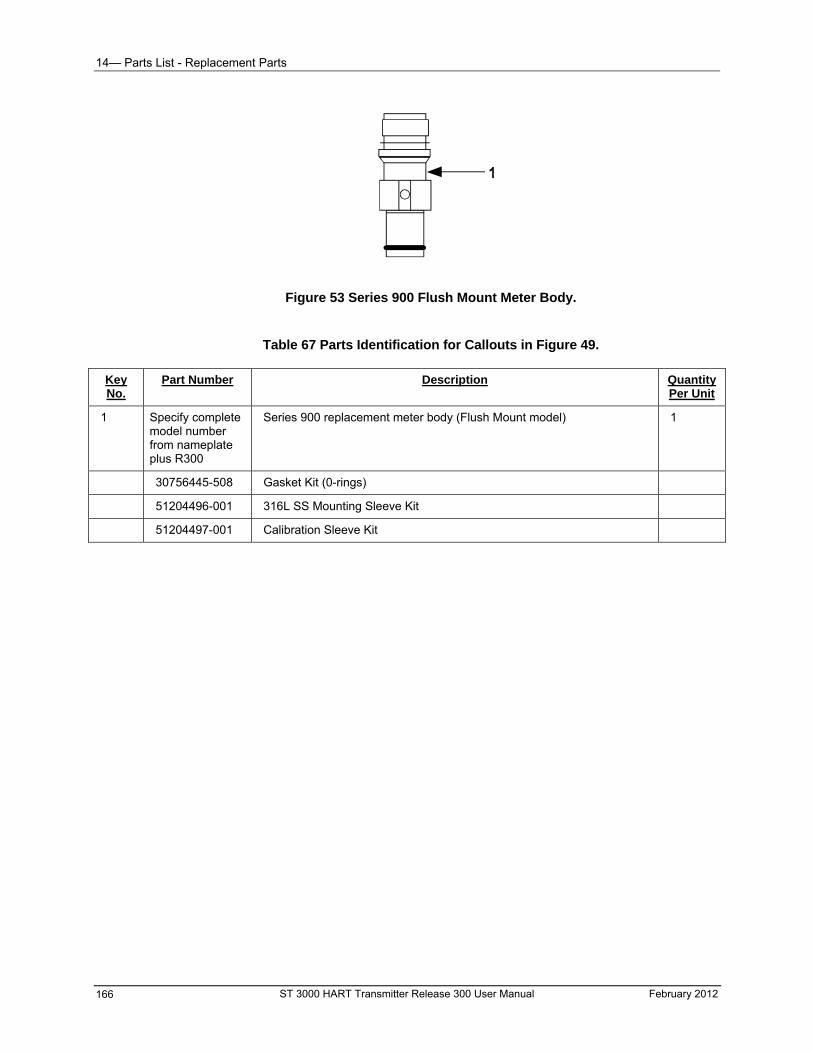
14— Parts List - Replacement Parts
Figure 53 Series 900 Flush Mount Meter Body.
Table 67 Parts Identification for Callouts in Figure 49.
Part Number Description Quantity Per Unit
Key No.
1 Specify complete model number from nameplate plus R300
Series 900 replacement meter body (Flush Mount model) 1
30756445-508 Gasket Kit (0-rings)
51204496-001 316L SS Mounting Sleeve Kit
51204497-001 Calibration Sleeve Kit
ST 3000 HART Transmitter Release 300 User Manual February 2012 166
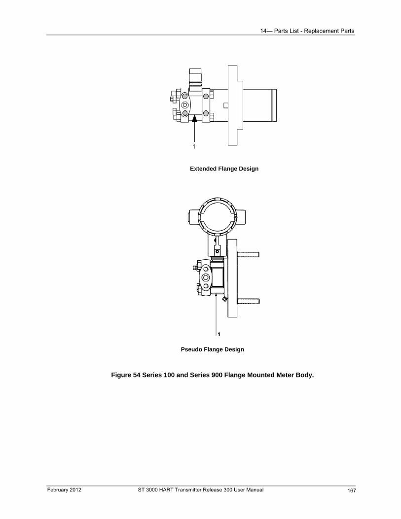
14— Parts List - Replacement Parts
1
Extended Flange Design
Pseudo Flange Design
Figure 54 Series 100 and Series 900 Flange Mounted Meter Body.
February 2012 ST 3000 HART Transmitter Release 300 User Manual 167
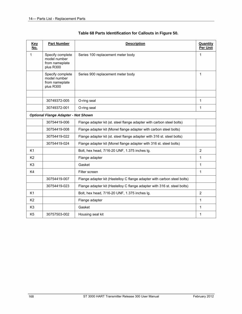
14— Parts List - Replacement Parts
Table 68 Parts Identification for Callouts in Figure 50.
Part Number Description Quantity Per Unit
Key No.
1 Specify complete model number from nameplate plus R300
Series 100 replacement meter body 1
Specify complete model number from nameplate plus R300
Series 900 replacement meter body 1
30749372-005 O-ring seal 1
30749372-001 O-ring seal 1
Optional Flange Adapter - Not Shown
30754419-006 Flange adapter kit (st. steel flange adapter with carbon steel bolts)
30754419-008 Flange adapter kit (Monel flange adapter with carbon steel bolts)
30754419-022 Flange adapter kit (st. steel flange adapter with 316 st. steel bolts)
30754419-024 Flange adapter kit (Monel flange adapter with 316 st. steel bolts)
K1 Bolt, hex head, 7/16-20 UNF, 1.375 inches lg. 2
K2 Flange adapter 1
K3 Gasket 1
K4 Filter screen 1
30754419-007 Flange adapter kit (Hastelloy C flange adapter with carbon steel bolts)
30754419-023 Flange adapter kit (Hastelloy C flange adapter with 316 st. steel bolts)
K1 Bolt, hex head, 7/16-20 UNF, 1.375 inches lg. 2
K2 Flange adapter 1
K3 Gasket 1
K5 30757503-002 Housing seal kit 1
ST 3000 HART Transmitter Release 300 User Manual February 2012 168
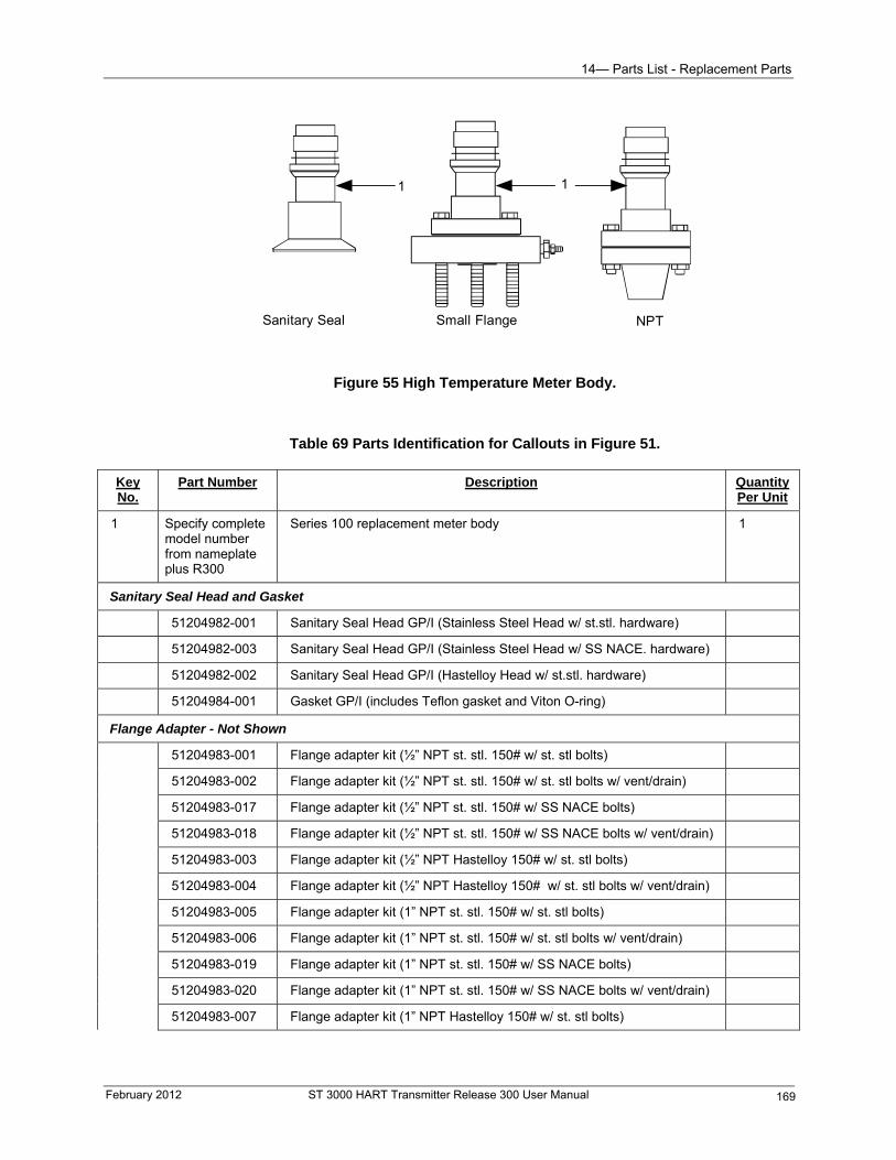
14— Parts List - Replacement Parts
11
Sanitary Seal Small Flange NPT
Figure 55 High Temperature Meter Body.
Table 69 Parts Identification for Callouts in Figure 51.
Key No.
Part Number Description Quantity Per Unit
1 Specify complete model number from nameplate plus R300
Series 100 replacement meter body 1
Sanitary Seal Head and Gasket
51204982-001 Sanitary Seal Head GP/I (Stainless Steel Head w/ st.stl. hardware)
51204982-003 Sanitary Seal Head GP/I (Stainless Steel Head w/ SS NACE. hardware)
51204982-002 Sanitary Seal Head GP/I (Hastelloy Head w/ st.stl. hardware)
51204984-001 Gasket GP/I (includes Teflon gasket and Viton O-ring)
Flange Adapter - Not Shown
51204983-001 Flange adapter kit (½” NPT st. stl. 150# w/ st. stl bolts)
51204983-002 Flange adapter kit (½” NPT st. stl. 150# w/ st. stl bolts w/ vent/drain)
51204983-017 Flange adapter kit (½” NPT st. stl. 150# w/ SS NACE bolts)
51204983-018 Flange adapter kit (½” NPT st. stl. 150# w/ SS NACE bolts w/ vent/drain)
51204983-003 Flange adapter kit (½” NPT Hastelloy 150# w/ st. stl bolts)
51204983-004 Flange adapter kit (½” NPT Hastelloy 150# w/ st. stl bolts w/ vent/drain)
51204983-005 Flange adapter kit (1” NPT st. stl. 150# w/ st. stl bolts)
51204983-006 Flange adapter kit (1” NPT st. stl. 150# w/ st. stl bolts w/ vent/drain)
51204983-019 Flange adapter kit (1” NPT st. stl. 150# w/ SS NACE bolts)
51204983-020 Flange adapter kit (1” NPT st. stl. 150# w/ SS NACE bolts w/ vent/drain)
51204983-007 Flange adapter kit (1” NPT Hastelloy 150# w/ st. stl bolts)
February 2012 ST 3000 HART Transmitter Release 300 User Manual 169
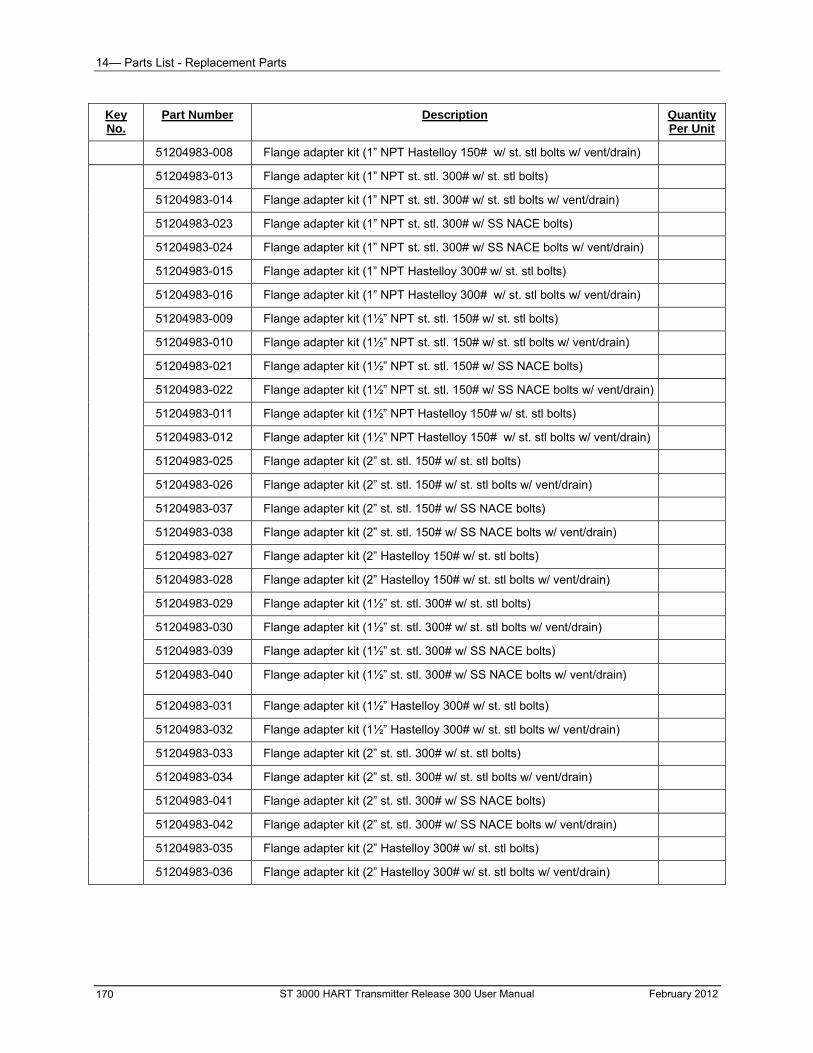
14— Parts List - Replacement Parts
Key No.
Part Number Description Quantity Per Unit
51204983-008 Flange adapter kit (1” NPT Hastelloy 150# w/ st. stl bolts w/ vent/drain)
51204983-013 Flange adapter kit (1” NPT st. stl. 300# w/ st. stl bolts)
51204983-014 Flange adapter kit (1” NPT st. stl. 300# w/ st. stl bolts w/ vent/drain)
51204983-023 Flange adapter kit (1” NPT st. stl. 300# w/ SS NACE bolts)
51204983-024 Flange adapter kit (1” NPT st. stl. 300# w/ SS NACE bolts w/ vent/drain)
51204983-015 Flange adapter kit (1” NPT Hastelloy 300# w/ st. stl bolts)
51204983-016 Flange adapter kit (1” NPT Hastelloy 300# w/ st. stl bolts w/ vent/drain)
51204983-009 Flange adapter kit (1½” NPT st. stl. 150# w/ st. stl bolts)
51204983-010 Flange adapter kit (1½” NPT st. stl. 150# w/ st. stl bolts w/ vent/drain)
51204983-021 Flange adapter kit (1½” NPT st. stl. 150# w/ SS NACE bolts)
51204983-022 Flange adapter kit (1½” NPT st. stl. 150# w/ SS NACE bolts w/ vent/drain)
51204983-011 Flange adapter kit (1½” NPT Hastelloy 150# w/ st. stl bolts)
51204983-012 Flange adapter kit (1½” NPT Hastelloy 150# w/ st. stl bolts w/ vent/drain)
51204983-025 Flange adapter kit (2” st. stl. 150# w/ st. stl bolts)
51204983-026 Flange adapter kit (2” st. stl. 150# w/ st. stl bolts w/ vent/drain)
51204983-037 Flange adapter kit (2” st. stl. 150# w/ SS NACE bolts)
51204983-038 Flange adapter kit (2” st. stl. 150# w/ SS NACE bolts w/ vent/drain)
51204983-027 Flange adapter kit (2” Hastelloy 150# w/ st. stl bolts)
51204983-028 Flange adapter kit (2” Hastelloy 150# w/ st. stl bolts w/ vent/drain)
51204983-029 Flange adapter kit (1½” st. stl. 300# w/ st. stl bolts)
51204983-030 Flange adapter kit (1½” st. stl. 300# w/ st. stl bolts w/ vent/drain)
51204983-039 Flange adapter kit (1½” st. stl. 300# w/ SS NACE bolts)
51204983-040 Flange adapter kit (1½” st. stl. 300# w/ SS NACE bolts w/ vent/drain)
51204983-031 Flange adapter kit (1½” Hastelloy 300# w/ st. stl bolts)
51204983-032 Flange adapter kit (1½” Hastelloy 300# w/ st. stl bolts w/ vent/drain)
51204983-033 Flange adapter kit (2” st. stl. 300# w/ st. stl bolts)
51204983-034 Flange adapter kit (2” st. stl. 300# w/ st. stl bolts w/ vent/drain)
51204983-041 Flange adapter kit (2” st. stl. 300# w/ SS NACE bolts)
51204983-042 Flange adapter kit (2” st. stl. 300# w/ SS NACE bolts w/ vent/drain)
51204983-035 Flange adapter kit (2” Hastelloy 300# w/ st. stl bolts)
51204983-036 Flange adapter kit (2” Hastelloy 300# w/ st. stl bolts w/ vent/drain)
ST 3000 HART Transmitter Release 300 User Manual February 2012 170
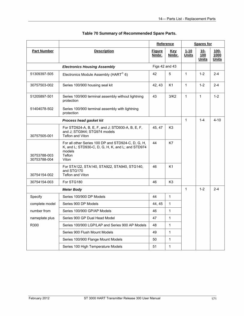
14— Parts List - Replacement Parts
Table 70 Summary of Recommended Spare Parts.
Reference Spares for
Part Number Description Figure Nmbr.
Key Nmbr.
1-10 Units
10-100
Units
100-1000 Units
Electronics Housing Assembly Figs 42 and 43
51309397-505
Electronics Module Assembly (HART 6) 42 5 1 1-2 2-4
30757503-002
Series 100/900 housing seal kit 42, 43 K1 1 1-2 2-4
51205897-501 51404078-502
Series 100/900 terminal assembly without lightning protection Series 100/900 terminal assembly with lightning protection
43 3/K2 1 1 1-2
Process head gasket kit 1 1-4 4-10
30757505-001
For STD924-A, B, E, F, and J; STD930-A, B, E, F, and J; STG944; STG974 models Teflon and Viton
45, 47 K3
30753788-003 30753788-004
For all other Series 100 DP and STD924-C, D, G, H, K, and L; STD930-C, D, G, H, K, and L; and STD974 models Teflon Viton
44 K7
30754154-002
For STA122, STA140, STA922, STA940, STG140, and STG170 Teflon and Viton
46 K1
30754154-003 For STG180 46 K3
Meter Body 1 1-2 2-4
Specify Series 100/900 DP Models 44 1
complete model Series 900 DP Models 44, 45 1
number from Series 100/900 GP/AP Models 46 1
nameplate plus Series 900 GP Dual Head Model 47 1
R300 Series 100/900 LGP/LAP and Series 900 AP Models 48 1
Series 900 Flush Mount Models 49 1
Series 100/900 Flange Mount Models 50 1
Series 100 High Temperature Models 51 1
February 2012 ST 3000 HART Transmitter Release 300 User Manual 171

- Replacement Parts
ST 3000 HART Transmitter Release 300 User Manual February 2012 172
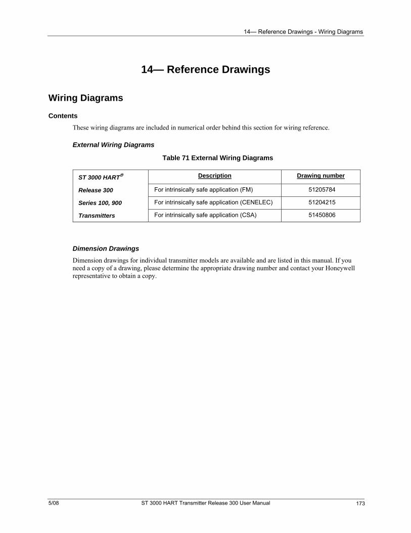
14— Reference Drawings - Wiring Diagrams
14— Reference Drawings
Wiring Diagrams
Contents
These wiring diagrams are included in numerical order behind this section for wiring reference.
External Wiring Diagrams
Table 71 External Wiring Diagrams
ST 3000 HART Description Drawing number
For intrinsically safe application (FM) 51205784 Release 300
For intrinsically safe application (CENELEC) 51204215 Series 100, 900
For intrinsically safe application (CSA) 51450806 Transmitters
Dimension Drawings
Dimension drawings for individual transmitter models are available and are listed in this manual. If you need a copy of a drawing, please determine the appropriate drawing number and contact your Honeywell representative to obtain a copy.
5/08 ST 3000 HART Transmitter Release 300 User Manual 173

14— Reference Drawings - Wiring Diagrams
ST 3000 HART Transmitter Release 300 User Manual February 2012 174

Appendix A— Smart Meter Reference - Introduction
Appendix A— Smart Meter Reference
Introduction
About this section
This section describes the integral smart meter options available with the ST 3000 Release 300 HARTtransmitter.
Procedures are given for setting range values of the transmitter using the smart meter pushbuttons.
You can use the meter pushbuttons or the HART communicator to set up the smart meter display to indicate transmitter PV output.
Typical smart meter indications are given as well as examples and descriptions of possible error codes displayed on the smart meter.
February 2012 ST 3000 HART Transmitter Release 300 User Manual 175
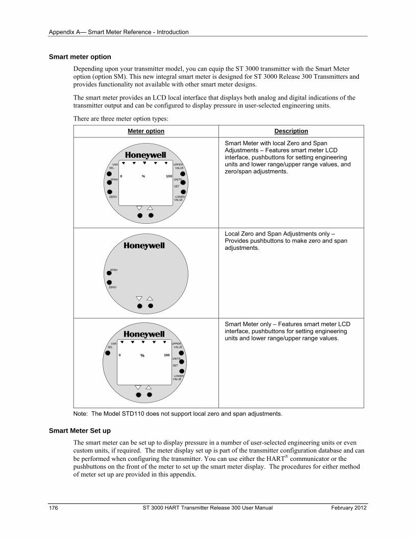
Appendix A— Smart Meter Reference - Introduction
Smart meter option
Depending upon your transmitter model, you can equip the ST 3000 transmitter with the Smart Meter option (option SM). This new integral smart meter is designed for ST 3000 Release 300 Transmitters and provides functionality not available with other smart meter designs.
The smart meter provides an LCD local interface that displays both analog and digital indications of the transmitter output and can be configured to display pressure in user-selected engineering units.
There are three meter option types:
Meter option Description
Smart Meter with local Zero and Span Adjustments – Features smart meter LCD interface, pushbuttons for setting engineering units and lower range/upper range values, and zero/span adjustments.
% 1000
UPPERVALUE
UNITS
LOWERVALUE
SET
VARSEL.
SPAN
ZERO
Local Zero and Span Adjustments only – Provides pushbuttons to make zero and span adjustments.
SPAN
ZERO
Smart Meter only – Features smart meter LCD interface, pushbuttons for setting engineering units and lower range/upper range values.
% 1000
UPPERVALUE
UNITS
LOWERVALUE
SET
VARSEL.
Note: The Model STD110 does not support local zero and span adjustments.
Smart Meter Set up
The smart meter can be set up to display pressure in a number of user-selected engineering units or even custom units, if required. The meter display set up is part of the transmitter configuration database and can be performed when configuring the transmitter. You can use either the HART communicator or the pushbuttons on the front of the meter to set up the smart meter display. The procedures for either method of meter set up are provided in this appendix.
ST 3000 HART Transmitter Release 300 User Manual February 2012 176
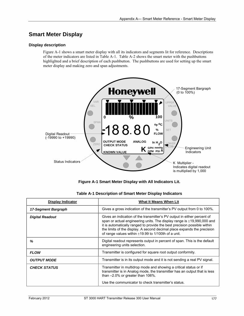
Appendix A— Smart Meter Reference - Smart Meter Display
Smart Meter Display
Display description
Figure A-1 shows a smart meter display with all its indicators and segments lit for reference. Descriptions of the meter indicators are listed in Table A-1. Table A-2 shows the smart meter with the pushbuttons highlighted and a brief description of each pushbutton. The pushbuttons are used for setting up the smart meter display and making zero and span adjustments.
UPPERVALUE
UNITS
LOWERVALUE
SET
% 1000
18 .808-ANALOG In H O
2
K GPH mmHgGPM PSI A
OUTPUT MODECHECK STATUS
KNOWN VALUE
%FLOW
oF oC
VAR
SEL.
SPAN
ZERO
Digital Readout (-19990 to +19990)
Status Indicators
17-Segment Bargraph (0 to 100%)
Engineering Unit Indicators
K Multiplier -Indicates digital readoutis multiplied by 1,000
Figure A-1 Smart Meter Display with All Indicators Lit.
Table A-1 Description of Smart Meter Display Indicators
Display Indicator What It Means When Lit
17-Segment Bargraph Gives a gross indication of the transmitter’s PV output from 0 to 100%.
Digital Readout Gives an indication of the transmitter’s PV output in either percent of span or actual engineering units. The display range is 19,990,000 and it is automatically ranged to provide the best precision possible within the limits of the display. A second decimal place expands the precision of range values within 19.99 to 1/100th of a unit.
Digital readout represents output in percent of span. This is the default engineering units selection.
%
Transmitter is configured for square root output conformity. FLOW
Transmitter is in its output mode and it is not sending a real PV signal. OUTPUT MODE
Transmitter in multidrop mode and showing a critical status or if transmitter is in Analog mode, the transmitter has an output that is less than –2.0% or greater than 106%.
CHECK STATUS
Use the communicator to check transmitter’s status.
February 2012 ST 3000 HART Transmitter Release 300 User Manual 177
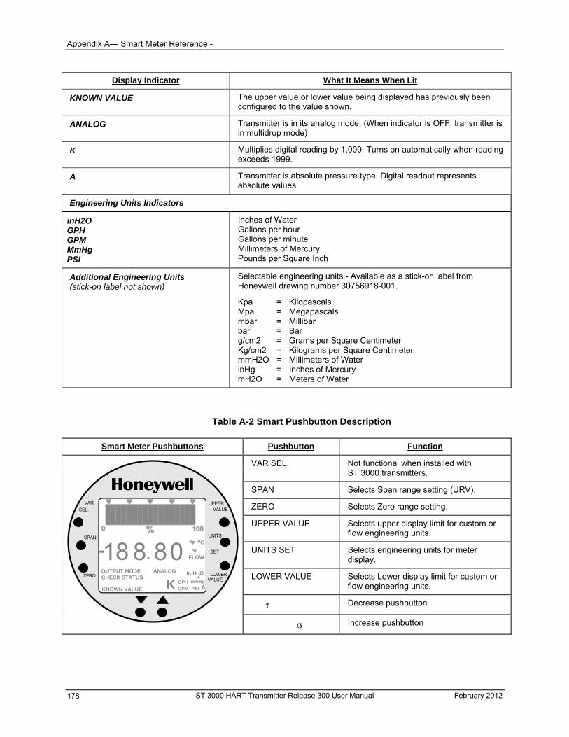
Appendix A— Smart Meter Reference -
ST 3000 HART Transmitter Release 300 User Manual February 2012 178
Display Indicator What It Means When Lit
KNOWN VALUE The upper value or lower value being displayed has previously been configured to the value shown.
ANALOG Transmitter is in its analog mode. (When indicator is OFF, transmitter is in multidrop mode)
K Multiplies digital reading by 1,000. Turns on automatically when reading exceeds 1999.
A Transmitter is absolute pressure type. Digital readout represents absolute values.
Engineering Units Indicators
inH2O GPH GPM MmHg PSI
Inches of Water Gallons per hour Gallons per minute Millimeters of Mercury Pounds per Square Inch
Additional Engineering Units (stick-on label not shown)
Selectable engineering units - Available as a stick-on label from Honeywell drawing number 30756918-001.
Kpa = Kilopascals Mpa = Megapascals mbar = Millibar bar = Bar g/cm2 = Grams per Square Centimeter Kg/cm2 = Kilograms per Square Centimeter mmH2O = Millimeters of Water inHg = Inches of Mercury mH2O = Meters of Water
Table A-2 Smart Pushbutton Description
Smart Meter Pushbuttons Pushbutton Function
VAR SEL. Not functional when installed with ST 3000 transmitters.
SPAN Selects Span range setting (URV).
ZERO Selects Zero range setting.
UPPER VALUE Selects upper display limit for custom or flow engineering units.
UNITS SET Selects engineering units for meter display.
LOWER VALUE Selects Lower display limit for custom or flow engineering units.
Decrease pushbutton
UPPERVALUE
UNITS
LOWERVALUE
SET
VAR
SEL.
SPAN
ZERO
18 .808-ANALOG In H O
2
K GPH mmHg
GPM PSI A
OUTPUT MODECHECK STATUS
KNOWN VALUE
%FLOW
oF oC
Increase pushbutton
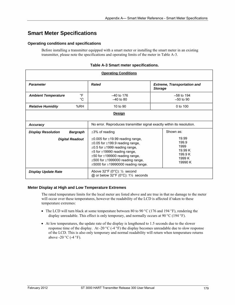
Appendix A— Smart Meter Reference - Smart Meter Specifications
Smart Meter Specifications
Operating conditions and specifications
Before installing a transmitter equipped with a smart meter or installing the smart meter in an existing transmitter, please note the specifications and operating limits of the meter in Table A-3.
Table A-3 Smart meter specifications.
Operating Conditions
Parameter Rated Extreme, Transportation and Storage
Ambient Temperature °F °C
–40 to 176 –40 to 80
–58 to 194 –50 to 90
Relative Humidity %RH 10 to 90 0 to 100
Design
No error. Reproduces transmitter signal exactly within its resolution. Accuracy
Shown as: 3% of reading Display Resolution Bargraph
19.99 199.9 1999 19.99 K 199.9 K 1999 K 19990 K
0.005 for 19.99 reading range, 0.05 for 199.9 reading range, 0.5 for 1999 reading range, 5 for 19990 reading range, 50 for 199900 reading range, 500 for 1999000 reading range, 5000 for 19990000 reading range.
Digital Readout
Above 32°F (0°C): ½ second @ or below 32°F (0°C): 1½ seconds
Display Update Rate
Meter Display at High and Low Temperature Extremes
The rated temperature limits for the local meter are listed above and are true in that no damage to the meter will occur over these temperatures, however the readability of the LCD is affected if taken to these temperature extremes:
The LCD will turn black at some temperature between 80 to 90 C (176 and 194 F), rendering the display unreadable. This effect is only temporary, and normally occurs at 90 C (194 F).
At low temperatures, the update rate of the display is lengthened to 1.5 seconds due to the slower response time of the display. At -20 C (-4 F) the display becomes unreadable due to slow response of the LCD. This is also only temporary and normal readability will return when temperature returns above -20 C (-4 F).
February 2012 ST 3000 HART Transmitter Release 300 User Manual 179
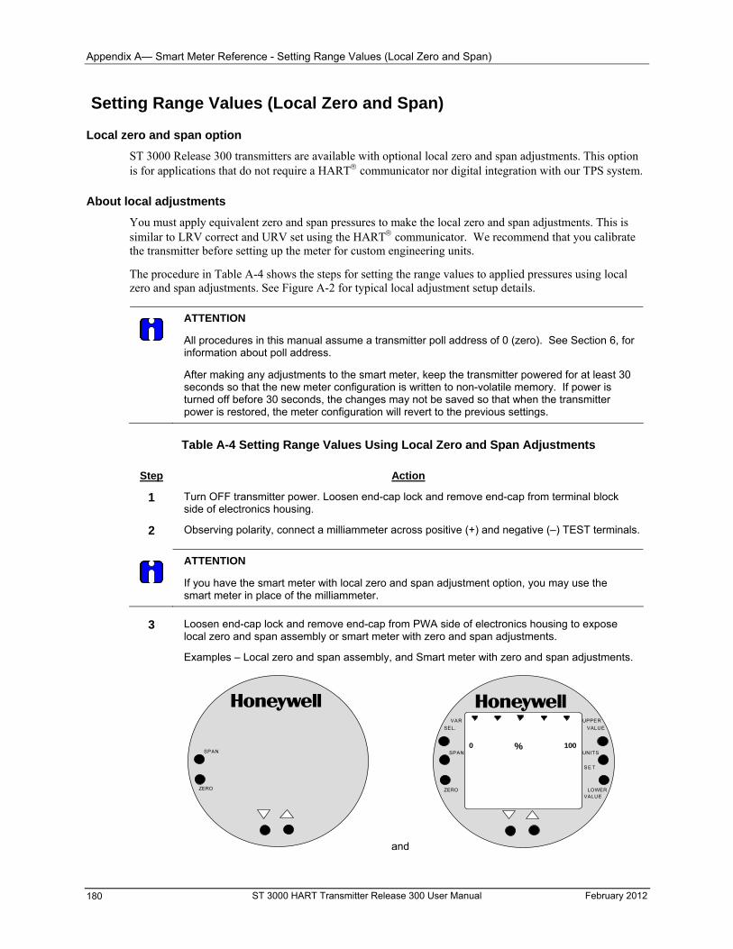
Appendix A— Smart Meter Reference - Setting Range Values (Local Zero and Span)
Setting Range Values (Local Zero and Span)
Local zero and span option
ST 3000 Release 300 transmitters are available with optional local zero and span adjustments. This option is for applications that do not require a HART communicator nor digital integration with our TPS system.
About local adjustments
You must apply equivalent zero and span pressures to make the local zero and span adjustments. This is similar to LRV correct and URV set using the HART communicator. We recommend that you calibrate the transmitter before setting up the meter for custom engineering units.
The procedure in Table A-4 shows the steps for setting the range values to applied pressures using local zero and span adjustments. See Figure A-2 for typical local adjustment setup details.
ATTENTION
All procedures in this manual assume a transmitter poll address of 0 (zero). See Section 6, for information about poll address.
After making any adjustments to the smart meter, keep the transmitter powered for at least 30 seconds so that the new meter configuration is written to non-volatile memory. If power is turned off before 30 seconds, the changes may not be saved so that when the transmitter power is restored, the meter configuration will revert to the previous settings.
Table A-4 Setting Range Values Using Local Zero and Span Adjustments
Step Action
1 Turn OFF transmitter power. Loosen end-cap lock and remove end-cap from terminal block side of electronics housing.
2 Observing polarity, connect a milliammeter across positive (+) and negative (–) TEST terminals.
ATTENTION
If you have the smart meter with local zero and span adjustment option, you may use the smart meter in place of the milliammeter.
3 Loosen end-cap lock and remove end-cap from PWA side of electronics housing to expose
local zero and span assembly or smart meter with zero and span adjustments.
Examples – Local zero and span assembly, and Smart meter with zero and span adjustments.
SPAN
ZERO
and
% 1000
UPPER
VALUE
UNITS
LOWERVALUE
S E T
VAR
SEL.
SPAN
ZERO
ST 3000 HART Transmitter Release 300 User Manual February 2012 180
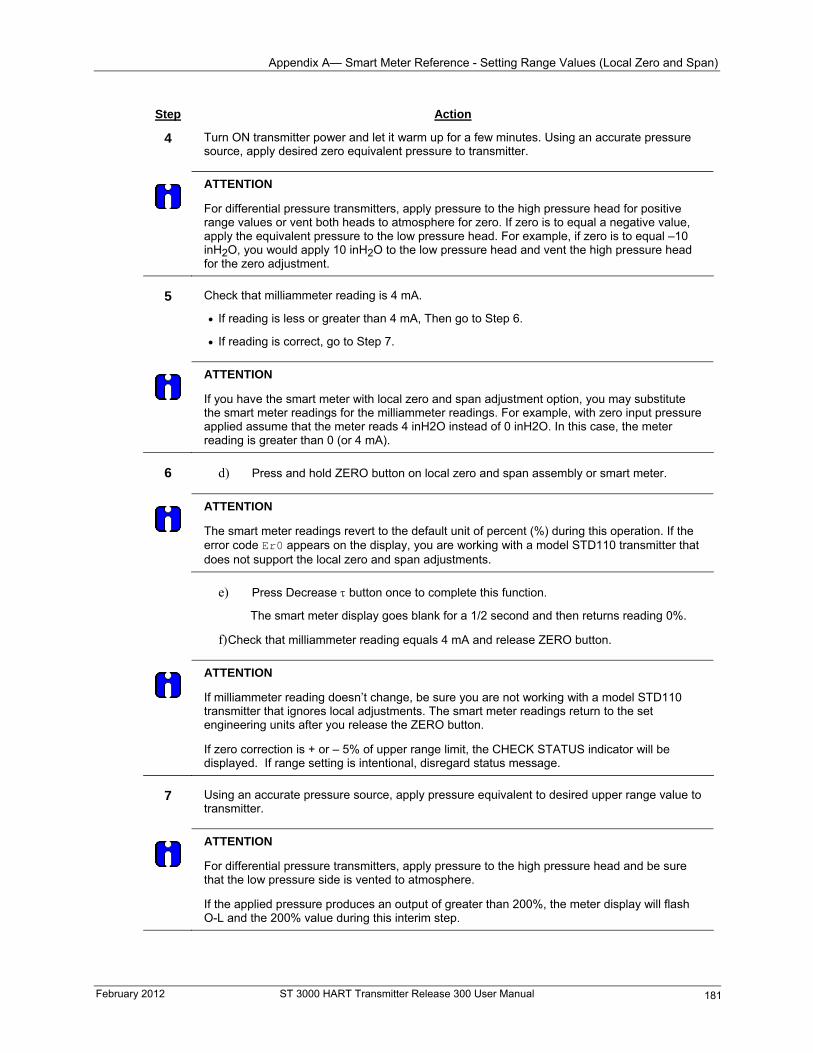
Appendix A— Smart Meter Reference - Setting Range Values (Local Zero and Span)
February 2012 ST 3000 HART Transmitter Release 300 User Manual 181
Step Action
4 Turn ON transmitter power and let it warm up for a few minutes. Using an accurate pressure source, apply desired zero equivalent pressure to transmitter.
ATTENTION
For differential pressure transmitters, apply pressure to the high pressure head for positive range values or vent both heads to atmosphere for zero. If zero is to equal a negative value, apply the equivalent pressure to the low pressure head. For example, if zero is to equal –10 inH2O, you would apply 10 inH2O to the low pressure head and vent the high pressure head for the zero adjustment.
5 Check that milliammeter reading is 4 mA.
If reading is less or greater than 4 mA, Then go to Step 6.
If reading is correct, go to Step 7.
ATTENTION
If you have the smart meter with local zero and span adjustment option, you may substitute the smart meter readings for the milliammeter readings. For example, with zero input pressure applied assume that the meter reads 4 inH2O instead of 0 inH2O. In this case, the meter reading is greater than 0 (or 4 mA).
6 d) Press and hold ZERO button on local zero and span assembly or smart meter.
ATTENTION
The smart meter readings revert to the default unit of percent (%) during this operation. If the error code Er0 appears on the display, you are working with a model STD110 transmitter that does not support the local zero and span adjustments.
e) Press Decrease button once to complete this function.
The smart meter display goes blank for a 1/2 second and then returns reading 0%.
f) Check that milliammeter reading equals 4 mA and release ZERO button.
ATTENTION
If milliammeter reading doesn’t change, be sure you are not working with a model STD110 transmitter that ignores local adjustments. The smart meter readings return to the set engineering units after you release the ZERO button.
If zero correction is + or – 5% of upper range limit, the CHECK STATUS indicator will be displayed. If range setting is intentional, disregard status message.
7 Using an accurate pressure source, apply pressure equivalent to desired upper range value to
transmitter.
ATTENTION
For differential pressure transmitters, apply pressure to the high pressure head and be sure that the low pressure side is vented to atmosphere.
If the applied pressure produces an output of greater than 200%, the meter display will flash O-L and the 200% value during this interim step.
Appendix A— Smart Meter Reference - Setting Range Values (Local Zero and Span)
ST 3000 HART Transmitter Release 300 User Manual February 2012 182
Step Action
8 Check that milliammeter reading is 20 mA.
If reading is not exactly 20 mA, Then go to Step 9.
If reading is correct, go to Step 10.
ATTENTION
If you have the smart meter with local zero and span adjustment option, you may substitute the smart meter readings for the milliammeter readings. For example, with URV input pressure applied, assume that the meter reads 396 inH2O instead of 400 inH2O. In this case, the meter reading is less than 100% (or 20 mA).
9 a) Press and hold SPAN button on local zero and span assembly or smart meter.
ATTENTION
The smart meter readings revert to the default unit of percent (%) during this operation. If the error code Er0 appears on the display, you are working with a model STD110 transmitter that does not support the local zero and span adjustments.
b) Press Increase button once to complete this function.
ATTENTION
If the error code Er4 appears, you are trying to set a SPAN value that is outside acceptable limits for your transmitter. Readjust applied pressure to be within acceptable range limits and repeat this procedure. The smart meter display goes blank for a 1/2 second and then returns reading 100%.
c) Check that milliammeter reading equals 20 mA and release SPAN button.
ATTENTION
If milliammeter reading doesn’t change, be sure you are not working with a model STD110 transmitter that ignores local adjustments. The smart meter readings return to the set engineering units after you release the SPAN button.
10 Wait 30 seconds so that changes are copied to the transmitter’s non-volatile memory.
11 Remove applied pressure and turn OFF transmitter power.
12 Replace end-cap on PWA side of electronics housing and tighten lock.
13 Remove milliammeter from TEST terminals and replace end-cap and tighten lock.
14 Turn ON transmitter power and check smart meter reading, if applicable.
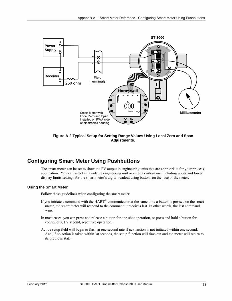
Appendix A— Smart Meter Reference - Configuring Smart Meter Using Pushbuttons
Smart Meter withLocal Zero and Spaninstalled on PWA sideof electronics housing
UPPERVALUE
UNITS
LOWERVALUE
SET
VAR
SEL.
SPAN
ZERO
% 1000
0AN ALOG In H O2
00
- S
IGN
AL
+
+
-T
ES
T
PowerSupply
+
-
Receiver
+
-
FieldTerminals
ST 3000
250 ohm
Milliammeter
Figure A-2 Typical Setup for Setting Range Values Using Local Zero and Span Adjustments.
Configuring Smart Meter Using Pushbuttons The smart meter can be set to show the PV output in engineering units that are appropriate for your process application. You can select an available engineering unit or enter a custom one including upper and lower display limits settings for the smart meter’s digital readout using buttons on the face of the meter.
Using the Smart Meter
Follow these guidelines when configuring the smart meter:
If you initiate a command with the HART communicator at the same time a button is pressed on the smart meter, the smart meter will respond to the command it receives last. In other words, the last command wins.
In most cases, you can press and release a button for one-shot operation, or press and hold a button for continuous, 1/2 second, repetitive operation.
Active setup field will begin to flash at one second rate if next action is not initiated within one second. And, if no action is taken within 30 seconds, the setup function will time out and the meter will return to its previous state.
February 2012 ST 3000 HART Transmitter Release 300 User Manual 183
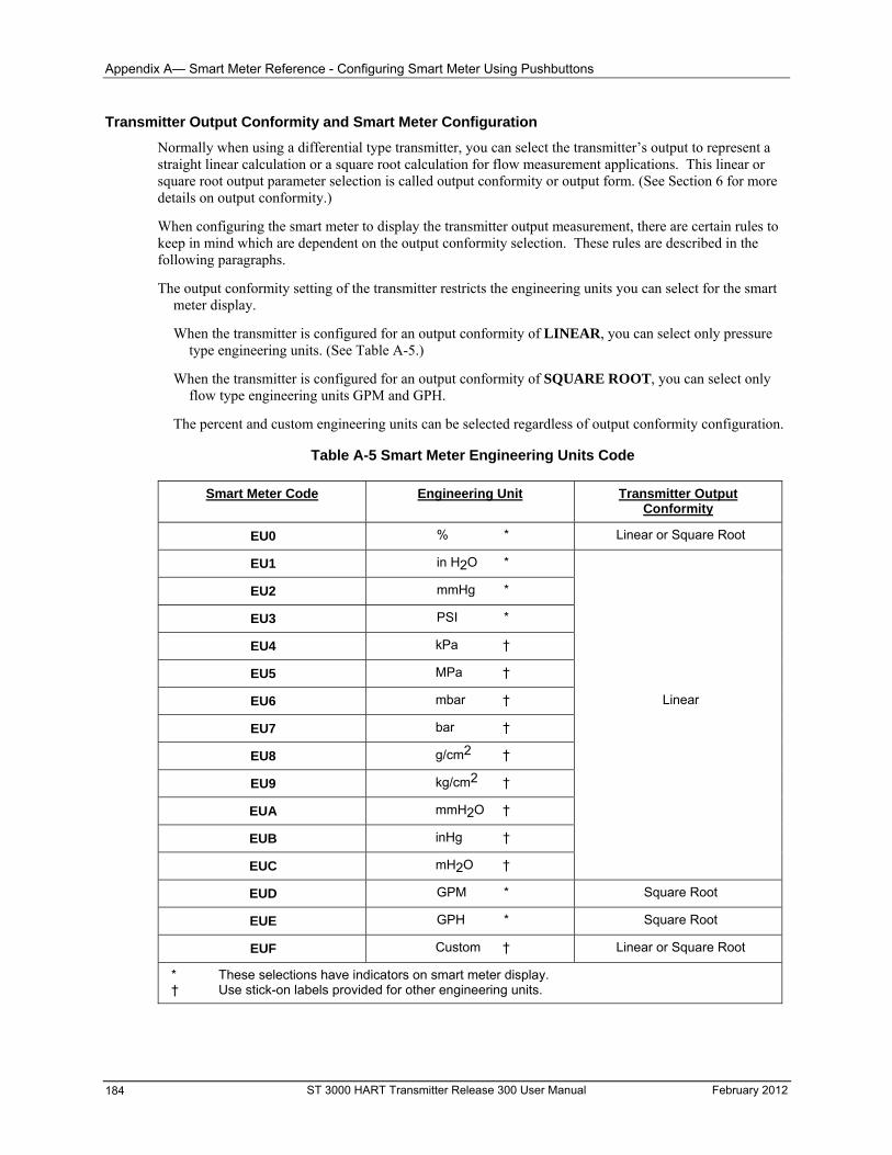
Appendix A— Smart Meter Reference - Configuring Smart Meter Using Pushbuttons
Transmitter Output Conformity and Smart Meter Configuration
Normally when using a differential type transmitter, you can select the transmitter’s output to represent a straight linear calculation or a square root calculation for flow measurement applications. This linear or square root output parameter selection is called output conformity or output form. (See Section 6 for more details on output conformity.)
When configuring the smart meter to display the transmitter output measurement, there are certain rules to keep in mind which are dependent on the output conformity selection. These rules are described in the following paragraphs.
The output conformity setting of the transmitter restricts the engineering units you can select for the smart meter display.
When the transmitter is configured for an output conformity of LINEAR, you can select only pressure type engineering units. (See Table A-5.)
When the transmitter is configured for an output conformity of SQUARE ROOT, you can select only flow type engineering units GPM and GPH.
The percent and custom engineering units can be selected regardless of output conformity configuration.
Table A-5 Smart Meter Engineering Units Code
Smart Meter Code Engineering Unit Transmitter Output Conformity
EU0 % * Linear or Square Root
EU1 in H2O *
EU2 mmHg *
EU3 PSI *
EU4 kPa †
EU5 MPa †
EU6 mbar † Linear
EU7 bar †
EU8 g/cm2 †
EU9 kg/cm2 †
EUA mmH2O †
EUB inHg †
EUC mH2O †
GPM * Square Root EUD
GPH * Square Root EUE
Custom † Linear or Square Root EUF
* These selections have indicators on smart meter display. † Use stick-on labels provided for other engineering units.
ST 3000 HART Transmitter Release 300 User Manual February 2012 184
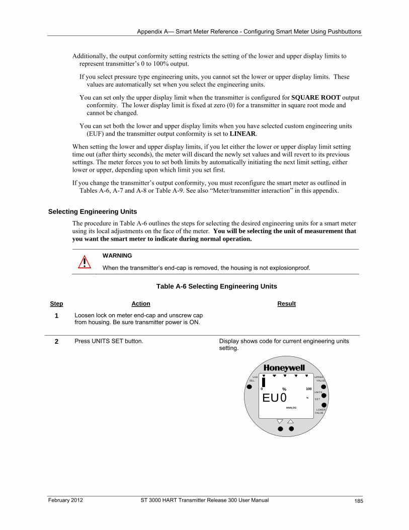
Appendix A— Smart Meter Reference - Configuring Smart Meter Using Pushbuttons
Additionally, the output conformity setting restricts the setting of the lower and upper display limits to represent transmitter’s 0 to 100% output.
If you select pressure type engineering units, you cannot set the lower or upper display limits. These values are automatically set when you select the engineering units.
You can set only the upper display limit when the transmitter is configured for SQUARE ROOT output conformity. The lower display limit is fixed at zero (0) for a transmitter in square root mode and cannot be changed.
You can set both the lower and upper display limits when you have selected custom engineering units (EUF) and the transmitter output conformity is set to LINEAR.
When setting the lower and upper display limits, if you let either the lower or upper display limit setting time out (after thirty seconds), the meter will discard the newly set values and will revert to its previous settings. The meter forces you to set both limits by automatically initiating the next limit setting, either lower or upper, depending upon which limit you set first.
If you change the transmitter’s output conformity, you must reconfigure the smart meter as outlined in Tables A-6, A-7 and A-8 or Table A-9. See also “Meter/transmitter interaction” in this appendix.
Selecting Engineering Units
The procedure in Table A-6 outlines the steps for selecting the desired engineering units for a smart meter using its local adjustments on the face of the meter. You will be selecting the unit of measurement that you want the smart meter to indicate during normal operation.
WARNING
When the transmitter’s end-cap is removed, the housing is not explosionproof.
Table A-6 Selecting Engineering Units Step Action Result
1 Loosen lock on meter end-cap and unscrew cap from housing. Be sure transmitter power is ON.
2 Press UNITS SET button. Display shows code for current engineering units setting.
% 1000
EUANALOG
%0
UPPER
VALUE
UNITS
LOWERVALUE
S E T
VAR
SEL.
February 2012 ST 3000 HART Transmitter Release 300 User Manual 185
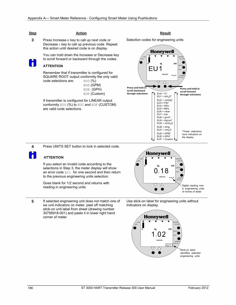
Appendix A— Smart Meter Reference - Configuring Smart Meter Using Pushbuttons
Step Action Result
3
Press Increase key to call up next code or Decrease key to call up previous code. Repeat this action until desired code is on display.
You can hold down the Increase or Decrease key to scroll forward or backward through the codes.
ATTENTION
Remember that if transmitter is configured for SQUARE ROOT output conformity the only valid code selections are: EU0 (%) EUD (GPM) EUE (GPH) EUF (Custom)
If transmitter is configured for LINEAR output conformity EU0 (%) to EUC and EUF (CUSTOM) are valid code selections.
Selection codes for engineering units
% 1000
EUANALOG
1
UPPER
VALUE
UNITS
LOWERVALUE
SE T
VAR
SEL.
In H O2
EU0 = %*EU1 = inH2O*
EU2 = mmHg*EU3 = PSI*EU4 = KPaEU5 = MPaEU6 = mbarEU7 = barEU8 = g/cm2
EU9 = Kg/cm2
EUA = mmH2O
EUB = inHgEUC = mH2O
EUD = GPM*EUE = GPH*EUF = Custom
Press and hold toscroll forwardthrough selections
Press and hold toscroll backwardthrough selections
*These selectionshave indicators onthe display.
4
Press UNITS SET button to lock in selected code.
ATTENTION
If you select an invalid code according to the selections in Step 3, the meter display will show an error code Er1 for one second and then return to the previous engineering units selection.
% 1000
0.1ANALOG
8
UPPER
VALUE
UNITS
LOWERVALUE
S E T
VAR
SEL.
In H O2
Digital reading nowin engineering unitsof inches of water
Goes blank for 1/2 second and returns with reading in engineering units
5 If selected engineering unit does not match one of six unit indicators on meter, peel off matching stick-on unit label from sheet (drawing number 30756918-001) and paste it in lower right hand corner of meter.
Use stick-on label for engineering units without indicators on display.
% 1000
1.0ANALOG
2
UPPER
VALUE
UNITS
LOWERVALUE
S E T
VAR
SEL.
Kg/cm2
Stick-on labelidentifies selectedengineering units
ST 3000 HART Transmitter Release 300 User Manual February 2012 186
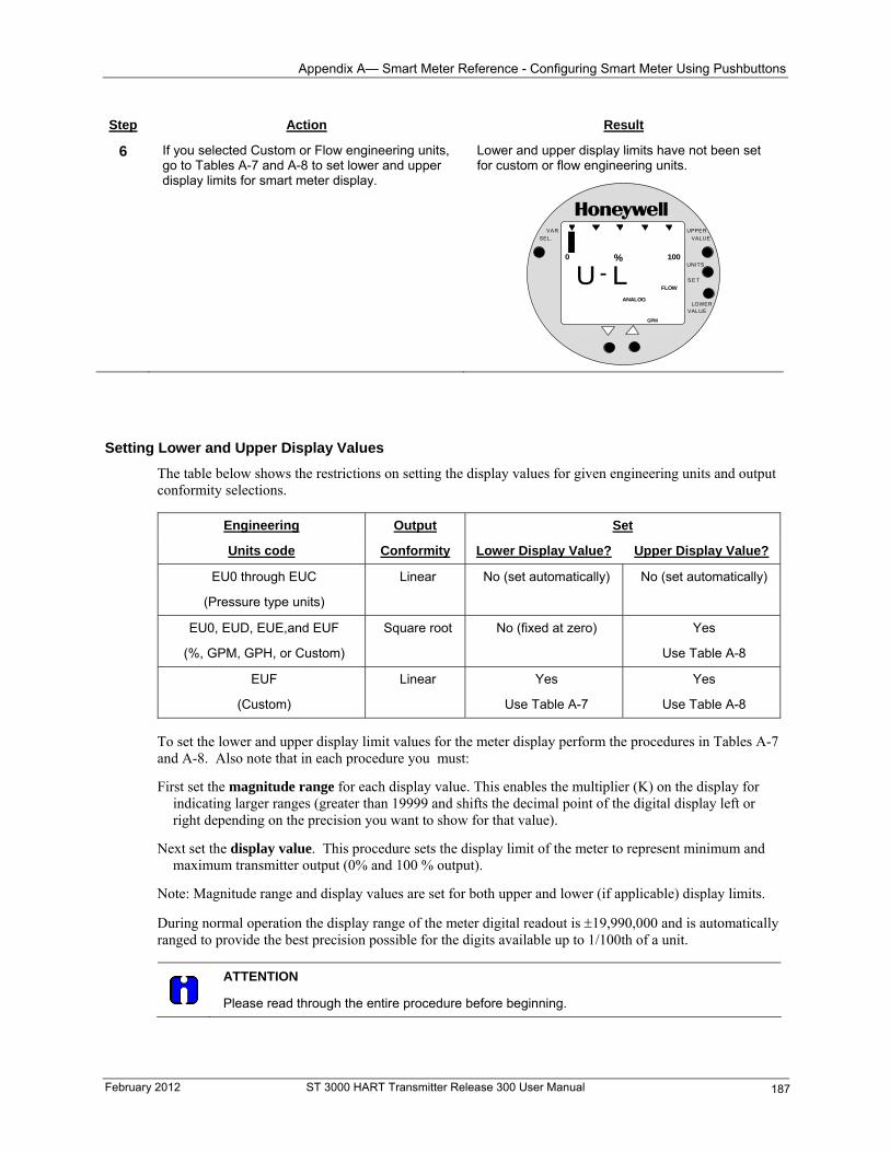
Appendix A— Smart Meter Reference - Configuring Smart Meter Using Pushbuttons
Step Action Result
6 If you selected Custom or Flow engineering units, go to Tables A-7 and A-8 to set lower and upper display limits for smart meter display.
Lower and upper display limits have not been set for custom or flow engineering units.
% 1000
U -ANALOG
L
UPPER
VALUE
UNITS
LOWERVALUE
S E T
VAR
SEL.
FLOW
GPM
Setting Lower and Upper Display Values
The table below shows the restrictions on setting the display values for given engineering units and output conformity selections.
Engineering Output Set
Units code Conformity Lower Display Value? Upper Display Value?
EU0 through EUC
(Pressure type units)
Linear No (set automatically) No (set automatically)
EU0, EUD, EUE,and EUF Square root No (fixed at zero) Yes
(%, GPM, GPH, or Custom) Use Table A-8
EUF
(Custom)
Linear Yes
Use Table A-7
Yes
Use Table A-8
To set the lower and upper display limit values for the meter display perform the procedures in Tables A-7 and A-8. Also note that in each procedure you must:
First set the magnitude range for each display value. This enables the multiplier (K) on the display for indicating larger ranges (greater than 19999 and shifts the decimal point of the digital display left or right depending on the precision you want to show for that value).
Next set the display value. This procedure sets the display limit of the meter to represent minimum and maximum transmitter output (0% and 100 % output).
Note: Magnitude range and display values are set for both upper and lower (if applicable) display limits.
During normal operation the display range of the meter digital readout is 19,990,000 and is automatically ranged to provide the best precision possible for the digits available up to 1/100th of a unit.
ATTENTION
Please read through the entire procedure before beginning.
February 2012 ST 3000 HART Transmitter Release 300 User Manual 187
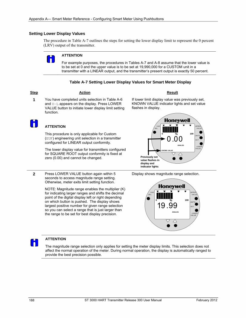
Appendix A— Smart Meter Reference - Configuring Smart Meter Using Pushbuttons
Setting Lower Display Values
The procedure in Table A-7 outlines the steps for setting the lower display limit to represent the 0 percent (LRV) output of the transmitter.
ATTENTION
For example purposes, the procedures in Tables A-7 and A-8 assume that the lower value is to be set at 0 and the upper value is to be set at 19,990,000 for a CUSTOM unit in a transmitter with a LINEAR output, and the transmitter’s present output is exactly 50 percent.
Table A-7 Setting Lower Display Values for Smart Meter Display Step Action Result
1
If lower limit display value was previously set, KNOWN VALUE indicator lights and set value flashes in display.
You have completed units selection in Table A-6 and U-L appears on the display. Press LOWER VALUE button to initiate lower display limit setting function.
% 1000
ANALOG
UPPER
VALUE
UNITS
LOWERVALUE
S E T
VAR
SEL.
0 . 00
Previously setvalue flashes indisplay andindicator lights
KNOWN VALUE
ATTENTION
This procedure is only applicable for Custom (EUF) engineering unit selection in a transmitter configured for LINEAR output conformity.
The lower display value for transmitters configured for SQUARE ROOT output conformity is fixed at zero (0.00) and cannot be changed.
2 Press LOWER VALUE button again within 5 seconds to access magnitude range setting. Otherwise, meter exits limit setting function.
NOTE: Magnitude range enables the multiplier (K) for indicating larger ranges and shifts the decimal point of the digital display left or right depending on which button is pushed. The display shows largest positive number for given range selection so you can select a range that is just larger than the range to be set for best display precision.
Display shows magnitude range selection.
% 1000
ANALOG
UPPER
VALUE
UNITS
LOWERVALUE
SE T
VAR
SEL.
19 .99
ATTENTION
The magnitude range selection only applies for setting the meter display limits. This selection does not affect the normal operation of the meter. During normal operation, the display is automatically ranged to provide the best precision possible.
ST 3000 HART Transmitter Release 300 User Manual February 2012 188
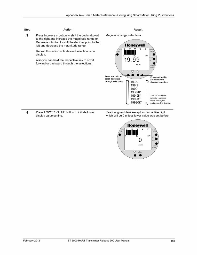
Appendix A— Smart Meter Reference - Configuring Smart Meter Using Pushbuttons
Step Action Result
3 Press Increase button to shift the decimal point to the right and increase the magnitude range or Decrease button to shift the decimal point to the left and decrease the magnitude range.
Repeat this action until desired selection is on display.
Also you can hold the respective key to scroll forward or backward through the selections.
Magnitude range selections.
% 1000
ANALOG
UPPER
VALUE
UNITS
LOWERVALUE
S E T
VAR
SEL.
19 . 99
19.99199.9199919.99K*199.9K*1999K*19990K*
Press and hold toscroll forwardthrough selections
Press and hold toscroll backwardthrough selections
*The "K" multiplierindicator appearsbelow the digitalreading on the display.
4 Press LOWER VALUE button to initiate lower display value setting.
Readout goes blank except for first active digit which will be 0 unless lower value was set before.
% 1000
ANALOG
UPPER
VALUE
UNITS
LOWERVALUE
S E T
VAR
SEL.
0
February 2012 ST 3000 HART Transmitter Release 300 User Manual 189
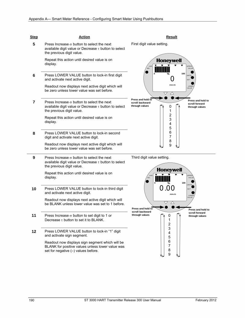
Appendix A— Smart Meter Reference - Configuring Smart Meter Using Pushbuttons
Step Action Result
5 Press Increase button to select the next available digit value or Decrease button to select the previous digit value.
Repeat this action until desired value is on display.
6 Press LOWER VALUE button to lock-in first digit and activate next active digit.
Readout now displays next active digit which will be zero unless lower value was set before.
7 Press Increase button to select the next available digit value or Decrease button to select the previous digit value.
Repeat this action until desired value is on display.
8 Press LOWER VALUE button to lock-in second digit and activate next active digit.
Readout now displays next active digit which will be zero unless lower value was set before.
First digit value setting.
% 1000
ANALOG
UPPER
VALUE
UNITS
LOWERVALUE
S E T
VAR
SEL.
0
0123456789
Press and hold toscroll forwardthrough values
Press and hold toscroll backwardthrough values
9 Press Increase button to select the next available digit value or Decrease button to select the previous digit value.
Repeat this action until desired value is on display.
Third digit value setting.
% 1000
ANALOG
UPPER
VALUE
UNITS
LOWERVALUE
S E T
VAR
SEL.
000 .
0123456789
Press and hold toscroll forwardthrough values
Press and hold toscroll backwardthrough values
10 Press LOWER VALUE button to lock-in third digit and activate next active digit.
Readout now displays next active digit which will be BLANK unless lower value was set to 1 before.
11 Press Increase button to set digit to 1 or Decrease button to set it to BLANK.
12 Press LOWER VALUE button to lock-in “1” digit and activate sign segment.
Readout now displays sign segment which will be BLANK for positive values unless lower value was set for negative (–) values before.
ST 3000 HART Transmitter Release 300 User Manual February 2012 190
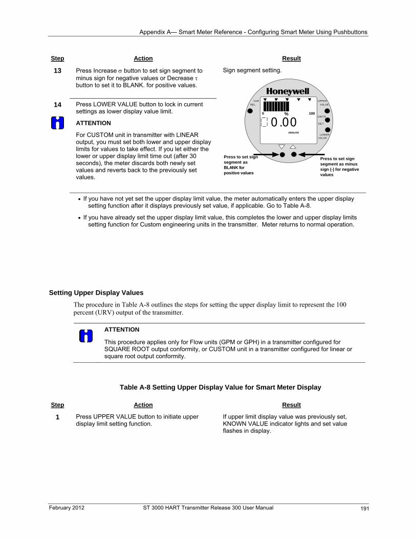
Appendix A— Smart Meter Reference - Configuring Smart Meter Using Pushbuttons
February 2012 ST 3000 HART Transmitter Release 300 User Manual 191
Step Action Result
13 Press Increase button to set sign segment to minus sign for negative values or Decrease button to set it to BLANK. for positive values.
14
Press LOWER VALUE button to lock in current settings as lower display value limit.
ATTENTION
For CUSTOM unit in transmitter with LINEAR output, you must set both lower and upper display limits for values to take effect. If you let either the lower or upper display limit time out (after 30 seconds), the meter discards both newly set values and reverts back to the previously set values.
Sign segment setting.
% 1000
ANALOG
UPPER
VALUE
UNITS
LOWERVALUE
S E T
VAR
SEL.
000 .
Press to set signsegment as minussign (-) for negativevalues
Press to set signsegment asBLANK forpositive values
If you have not yet set the upper display limit value, the meter automatically enters the upper display setting function after it displays previously set value, if applicable. Go to Table A-8.
If you have already set the upper display limit value, this completes the lower and upper display limits setting function for Custom engineering units in the transmitter. Meter returns to normal operation.
Setting Upper Display Values
The procedure in Table A-8 outlines the steps for setting the upper display limit to represent the 100 percent (URV) output of the transmitter.
ATTENTION
This procedure applies only for Flow units (GPM or GPH) in a transmitter configured for SQUARE ROOT output conformity, or CUSTOM unit in a transmitter configured for linear or square root output conformity.
Table A-8 Setting Upper Display Value for Smart Meter Display Step Action Result
1 Press UPPER VALUE button to initiate upper display limit setting function.
If upper limit display value was previously set, KNOWN VALUE indicator lights and set value flashes in display.
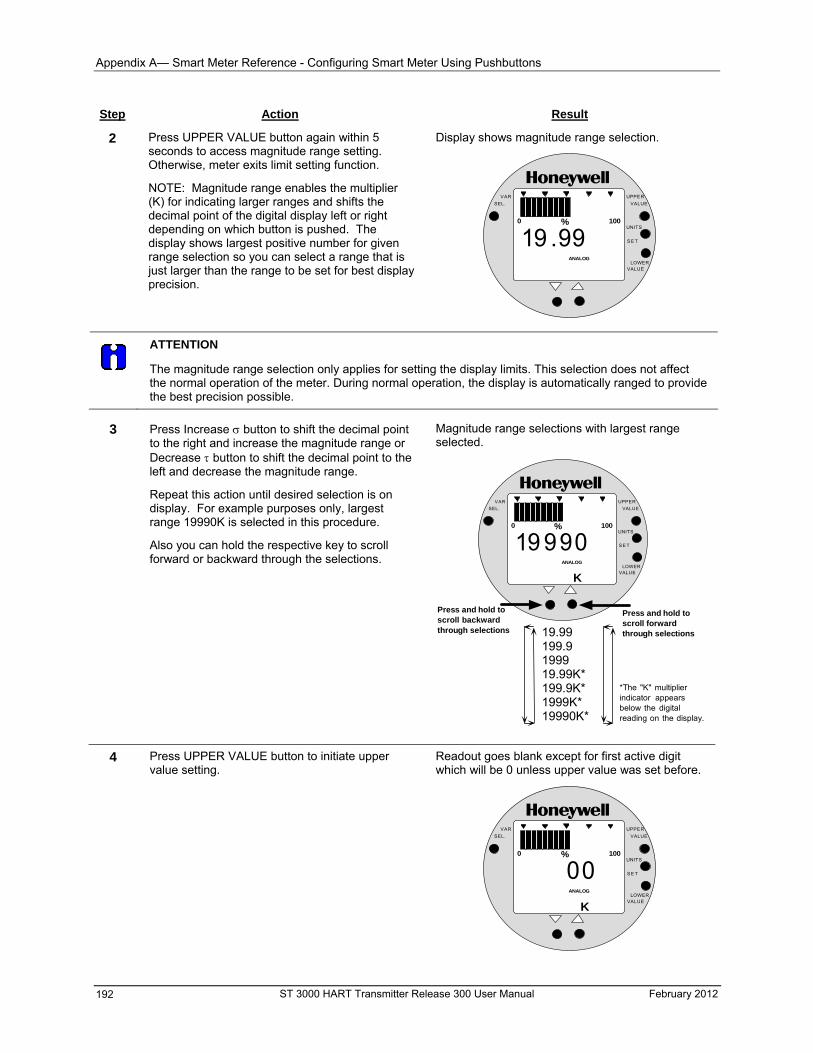
Appendix A— Smart Meter Reference - Configuring Smart Meter Using Pushbuttons
Step Action Result
2 Press UPPER VALUE button again within 5 seconds to access magnitude range setting. Otherwise, meter exits limit setting function.
NOTE: Magnitude range enables the multiplier (K) for indicating larger ranges and shifts the decimal point of the digital display left or right depending on which button is pushed. The display shows largest positive number for given range selection so you can select a range that is just larger than the range to be set for best display precision.
Display shows magnitude range selection.
% 1000
ANALOG
UPPER
VALUE
UNITS
LOWERVALUE
S E T
VAR
SEL.
19 .99
ATTENTION
The magnitude range selection only applies for setting the display limits. This selection does not affect the normal operation of the meter. During normal operation, the display is automatically ranged to provide the best precision possible.
3 Press Increase button to shift the decimal point
to the right and increase the magnitude range or Decrease button to shift the decimal point to the left and decrease the magnitude range.
Repeat this action until desired selection is on display. For example purposes only, largest range 19990K is selected in this procedure.
Also you can hold the respective key to scroll forward or backward through the selections.
Magnitude range selections with largest range selected.
% 1000
ANALOG
UPPER
VALUE
UNITS
LOWERVALUE
S E T
VAR
SEL.
19.99199.9199919.99K*199.9K*1999K*19990K*
Press and hold toscroll forwardthrough selections
Press and hold toscroll backwardthrough selections
*The "K" multiplierindicator appearsbelow the digitalreading on the display.
K
19 990
4 Press UPPER VALUE button to initiate upper value setting.
Readout goes blank except for first active digit which will be 0 unless upper value was set before.
% 1000
ANALOG
UPPER
VALUE
UNITS
LOWERVALUE
S E T
VAR
SEL.
K
00
ST 3000 HART Transmitter Release 300 User Manual February 2012 192
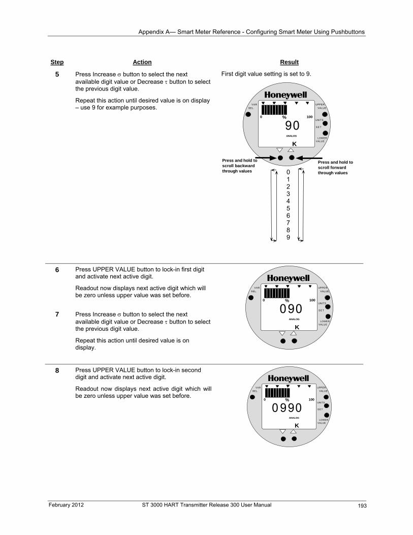
Appendix A— Smart Meter Reference - Configuring Smart Meter Using Pushbuttons
Step Action Result
5 Press Increase button to select the next available digit value or Decrease button to select the previous digit value.
First digit value setting is set to 9.
Repeat this action until desired value is on display – use 9 for example purposes.
% 1000
ANALOG
UPPER
VALUE
UNITS
LOWERVALUE
S E T
VAR
SEL.
K
90
0123456789
Press and hold toscroll forwardthrough values
Press and hold toscroll backwardthrough values
6 Press UPPER VALUE button to lock-in first digit and activate next active digit.
Readout now displays next active digit which will be zero unless upper value was set before.
7
% 1000
ANALOG
UPPER
VALUE
UNITS
LOWERVALUE
S E T
VAR
SEL.
K
090
Press Increase button to select the next available digit value or Decrease button to select the previous digit value.
Repeat this action until desired value is on display.
8 Press UPPER VALUE button to lock-in second digit and activate next active digit.
Readout now displays next active digit which will be zero unless upper value was set before.
% 1000
ANALOG
UPPER
VALUE
UNITS
LOWERVALUE
S E T
VAR
SEL.
K
0 990
February 2012 ST 3000 HART Transmitter Release 300 User Manual 193
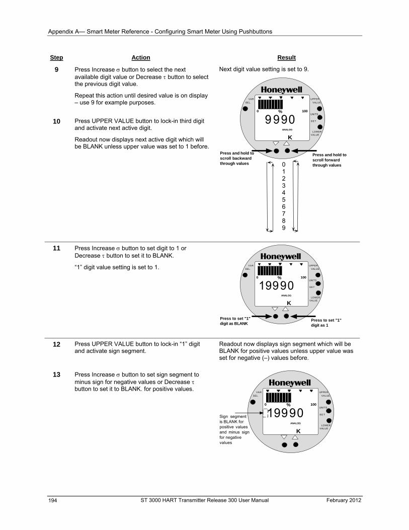
Appendix A— Smart Meter Reference - Configuring Smart Meter Using Pushbuttons
Step Action Result
9 Press Increase button to select the next available digit value or Decrease button to select the previous digit value.
Repeat this action until desired value is on display – use 9 for example purposes.
10 Press UPPER VALUE button to lock-in third digit and activate next active digit.
Next digit value setting is set to 9.
Readout now displays next active digit which will be BLANK unless upper value was set to 1 before.
% 1000
ANALOG
UPPER
VALUE
UNITS
LOWERVALUE
S E T
VAR
SEL.
K
9 990
0123456789
Press and hold toscroll forwardthrough values
Press and hold toscroll backwardthrough values
11 Press Increase button to set digit to 1 or Decrease button to set it to BLANK.
“1” digit value setting is set to 1.
% 1000
ANALOG
UPPER
VALUE
UNITS
LOWERVALUE
S E T
VAR
SEL.
K
9990
Press to set "1"digit as 1
Press to set "1"digit as BLANK
1
12 Press UPPER VALUE button to lock-in “1” digit and activate sign segment.
Readout now displays sign segment which will be BLANK for positive values unless upper value was set for negative (–) values before.
13 Press Increase button to set sign segment to minus sign for negative values or Decrease button to set it to BLANK. for positive values.
% 1000
ANALOG
UPPER
VALUE
UNITS
LOWERVALUE
S E T
VAR
SEL.
K
99901Sign segmentis BLANK forpositive valuesand minus signfor negativevalues
ST 3000 HART Transmitter Release 300 User Manual February 2012 194
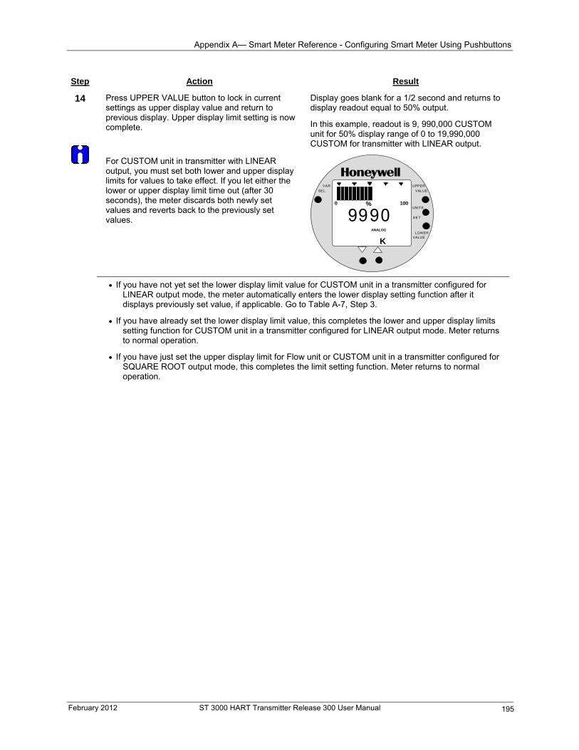
Appendix A— Smart Meter Reference - Configuring Smart Meter Using Pushbuttons
February 2012 ST 3000 HART Transmitter Release 300 User Manual 195
Step Action Result
14
Press UPPER VALUE button to lock in current settings as upper display value and return to previous display. Upper display limit setting is now complete.
For CUSTOM unit in transmitter with LINEAR output, you must set both lower and upper display limits for values to take effect. If you let either the lower or upper display limit time out (after 30 seconds), the meter discards both newly set values and reverts back to the previously set values.
Display goes blank for a 1/2 second and returns to display readout equal to 50% output.
In this example, readout is 9, 990,000 CUSTOM unit for 50% display range of 0 to 19,990,000 CUSTOM for transmitter with LINEAR output.
% 1000
ANALOG
UPPER
VALUE
UNITS
LOWERVALUE
S E T
VAR
SEL.
K
9990
If you have not yet set the lower display limit value for CUSTOM unit in a transmitter configured for LINEAR output mode, the meter automatically enters the lower display setting function after it displays previously set value, if applicable. Go to Table A-7, Step 3.
If you have already set the lower display limit value, this completes the lower and upper display limits setting function for CUSTOM unit in a transmitter configured for LINEAR output mode. Meter returns to normal operation.
If you have just set the upper display limit for Flow unit or CUSTOM unit in a transmitter configured for SQUARE ROOT output mode, this completes the limit setting function. Meter returns to normal operation.
Appendix A— Smart Meter Reference - Setting smart meter display using the HART communicator
Setting smart meter display using the HART communicator
Using the Hart Communicator to Configure the Smart Meter Display
You can select an available engineering unit or enter a custom one including upper and lower limit settings for the smart meter’s digital readout using the HART communicator. Use the procedure in Table A-9 to setup the smart meter display with the HART communicator.
Transmitter Output Conformity and Smart Meter Configuration
Normally when using a differential type transmitter, you can select the transmitter’s output to represent a straight linear calculation or a square root calculation for flow measurement applications. This linear or square root output parameter selection is called output conformity or output form. (See Section 6 in this User manual for more details.)
When configuring the smart meter to display the transmitter output measurement, there are certain rules to keep in mind which are dependent on the output conformity selection. These rules are described in the following paragraphs. Refer to Table A-5 also for meter set up restrictions.
1. The output conformity setting of the transmitter restricts the engineering units you can select for the smart meter display.
When the transmitter is configured for an output conformity of LINEAR, you can select only pressure type engineering units. (See Table A-5.)
When the transmitter is configured for an output conformity of SQUARE ROOT, you can select only flow type engineering units GPM and GPH.
The percent (%) and custom engineering units can be selected regardless of output conformity configuration.
2. Additionally, the output conformity setting restricts the setting of the lower and upper display limits to represent transmitter’s 0 to 100% output. The table below shows the restrictions on setting display values for given engineering units and output conformity selections.
Engineering Output Set
Units code Conformity Lower Display Value? Upper Display Value?
EU0 through EUC
(Pressure type units)
Linear No (set automatically) No (set automatically)
EU0, EUD, EUE,and EUF
(%, GPM, GPH, or Custom)
Square root No (fixed at zero) Yes
Custom Linear Yes Yes
3. If you change the transmitter’s output conformity, you must reconfigure the smart meter as outlined in Table A-9. See also “Meter/transmitter interaction” in this appendix.
ATTENTION
After making any adjustments to the smart meter, keep the transmitter powered for at least 30 seconds so that the new meter configuration is written to non-volatile memory. If power is turned off before 30 seconds, the changes may not be saved so that when the transmitter power is restored, the meter configuration will revert to the previous settings.
ST 3000 HART Transmitter Release 300 User Manual February 2012 196
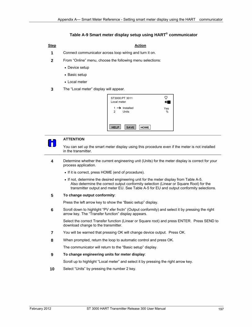
Appendix A— Smart Meter Reference - Setting smart meter display using the HART communicator
February 2012 ST 3000 HART Transmitter Release 300 User Manual 197
Table A-9 Smart meter display setup using HART communicator
Step Action
1 Connect communicator across loop wiring and turn it on.
2 From “Online” menu, choose the following menu selections:
Device setup
Basic setup
Local meter
3 The “Local meter” display will appear.
ST3000:PT 3011Local meter
12
InstalledUnits %
Yes
HELP SAVE HOME
ATTENTION
You can set up the smart meter display using this procedure even if the meter is not installed in the transmitter.
4 Determine whether the current engineering unit (Units) for the meter display is correct for your
process application.
If it is correct, press HOME (end of procedure).
If not, determine the desired engineering unit for the meter display from Table A-5. Also determine the correct output conformity selection (Linear or Square Root) for the transmitter output and meter EU. See Table A-5 for EU and output conformity selections.
5 To change output conformity:
Press the left arrow key to show the “Basic setup” display.
6 Scroll down to highlight “PV xfer fnctn” (Output conformity) and select it by pressing the right arrow key. The “Transfer function” display appears.
Select the correct Transfer function (Linear or Square root) and press ENTER. Press SEND to download change to the transmitter.
7 You will be warned that pressing OK will change device output. Press OK.
8 When prompted, return the loop to automatic control and press OK.
The communicator will return to the “Basic setup” display.
9 To change engineering units for meter display:
Scroll up to highlight “Local meter” and select it by pressing the right arrow key.
10
Select “Units” by pressing the number 2 key.
Appendix A— Smart Meter Reference - Setting smart meter display using the HART communicator
Step Action
11 Scroll through the list of engineering units using the up and down arrow keys and select the desired units, then press ENTER. The available units are listed below for reference.
% mbar mH2O
inH2O bar gal/min
mmHg g/Sqcm gal/h
psi kg/Sqcm Custom
kPa mmH2O
MPa inHg
Note: Be sure that the engineering unit that is selected is compatible with the output conformity selection in Table A-5.
12 Press SEND to download change to the transmitter.
13 If “Upper” and “Lower” appear on the screen, select Upper and enter the upper limit value for the meter display. Press ENTER.
Select Lower and enter the lower limit value for the meter display. Press ENTER.
Note: If square root output conformity is selected, the lower display limit is fixed at zero and cannot be changed.
14 Press SEND to download changes to the transmitter.
ATTENTION
If an error message appears,
“Invalid unit occurred writing Units. Restore device value?” or “Invalid meter option occurred writing Lower. Restore device value?”
You have tried to download an invalid parameter for the meter display.
ST 3000 HART Transmitter Release 300 User Manual February 2012 198
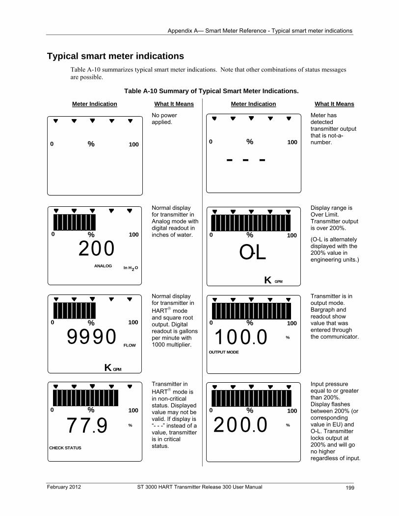
Appendix A— Smart Meter Reference - Typical smart meter indications
Typical smart meter indications Table A-10 summarizes typical smart meter indications. Note that other combinations of status messages are possible.
Table A-10 Summary of Typical Smart Meter Indications.
Meter Indication What It Means Meter Indication What It Means
% 1000
No power applied.
% 1000
- - -
Meter has detected transmitter output that is not-a-number.
% 1000
20ANALOG In H O2
0
Normal display for transmitter in Analog mode with digital readout in inches of water.
Display range is Over Limit. Transmitter output is over 200%.
% 1000
O-LK GPM
(O-L is alternately displayed with the 200% value in engineering units.)
% 1000
FLOW
GPMK
9990
Normal display for transmitter in HART mode and square root output. Digital readout is gallons per minute with 1000 multiplier.
Transmitter is in output mode. Bargraph and readout show value that was entered through the communicator.
% 1000
100.0 %
OUTPUT MODE
Transmitter in HART mode is in non-critical status. Displayed value may not be valid. If display is “- - -” instead of a value, transmitter is in critical status.
% 1000
200.0 %
Input pressure equal to or greater than 200%. Display flashes between 200% (or corresponding value in EU) and O-L. Transmitter locks output at 200% and will go no higher regardless of input.
% 1000
77.9 %
CHECK STATUS
February 2012 ST 3000 HART Transmitter Release 300 User Manual 199
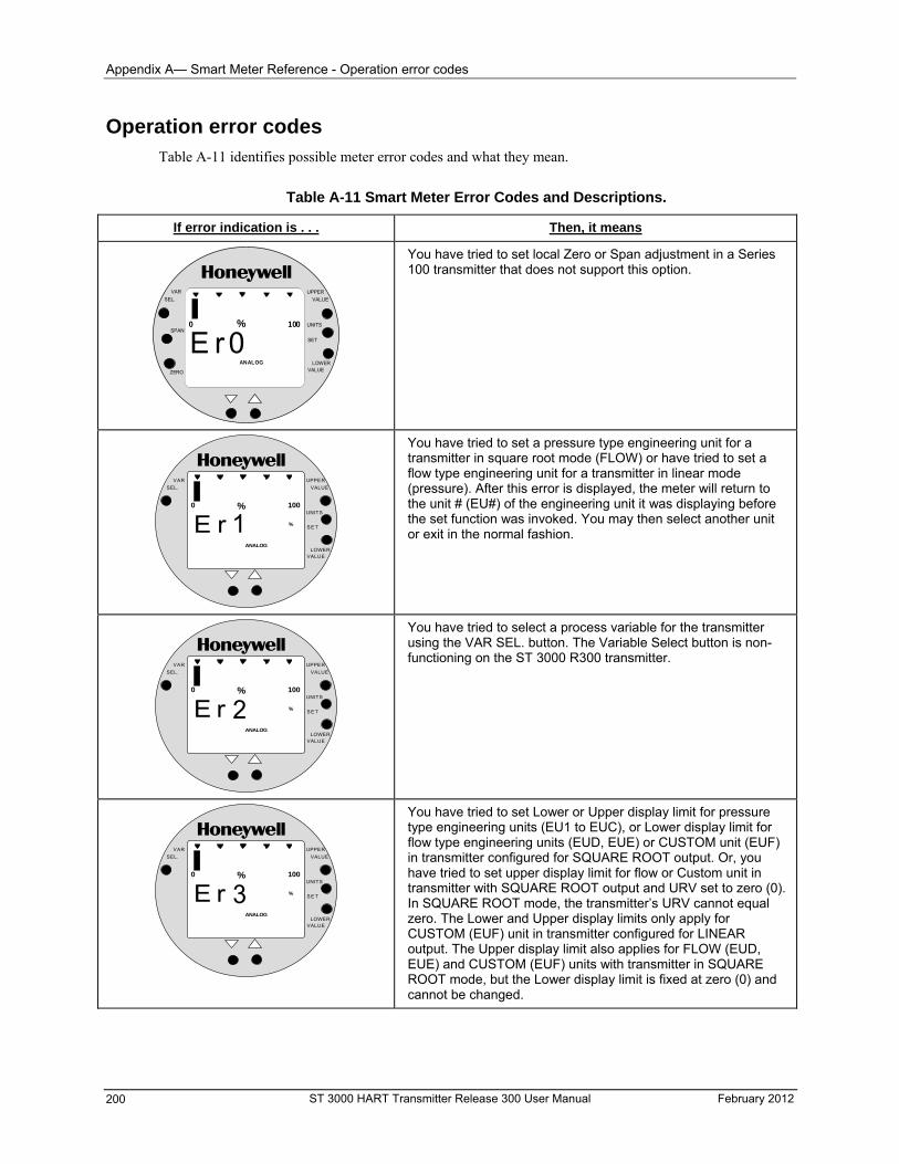
Appendix A— Smart Meter Reference - Operation error codes
Operation error codes Table A-11 identifies possible meter error codes and what they mean.
Table A-11 Smart Meter Error Codes and Descriptions.
If error indication is . . . Then, it means
UPPER
VALUE
UNITS
LOWERVALUE
SET
VAR
SEL.
SPAN
ZERO
% 1000
ANALOG
E r 0
You have tried to set local Zero or Span adjustment in a Series 100 transmitter that does not support this option.
% 1000
E rANALOG
%1
UPPER
VALUE
UNITS
LOWERVALUE
S E T
VAR
SEL.
You have tried to set a pressure type engineering unit for a transmitter in square root mode (FLOW) or have tried to set a flow type engineering unit for a transmitter in linear mode (pressure). After this error is displayed, the meter will return to the unit # (EU#) of the engineering unit it was displaying before the set function was invoked. You may then select another unit or exit in the normal fashion.
% 1000
E rANALOG
%2
UPPER
VALUE
UNITS
LOWERVALUE
S E T
VAR
SEL.
You have tried to select a process variable for the transmitter using the VAR SEL. button. The Variable Select button is non-functioning on the ST 3000 R300 transmitter.
% 1000
E rANALOG
%3
UPPER
VALUE
UNITS
LOWERVALUE
S E T
VAR
SEL.
You have tried to set Lower or Upper display limit for pressure type engineering units (EU1 to EUC), or Lower display limit for flow type engineering units (EUD, EUE) or CUSTOM unit (EUF) in transmitter configured for SQUARE ROOT output. Or, you have tried to set upper display limit for flow or Custom unit in transmitter with SQUARE ROOT output and URV set to zero (0). In SQUARE ROOT mode, the transmitter’s URV cannot equal zero. The Lower and Upper display limits only apply for CUSTOM (EUF) unit in transmitter configured for LINEAR output. The Upper display limit also applies for FLOW (EUD, EUE) and CUSTOM (EUF) units with transmitter in SQUARE ROOT mode, but the Lower display limit is fixed at zero (0) and cannot be changed.
ST 3000 HART Transmitter Release 300 User Manual February 2012 200
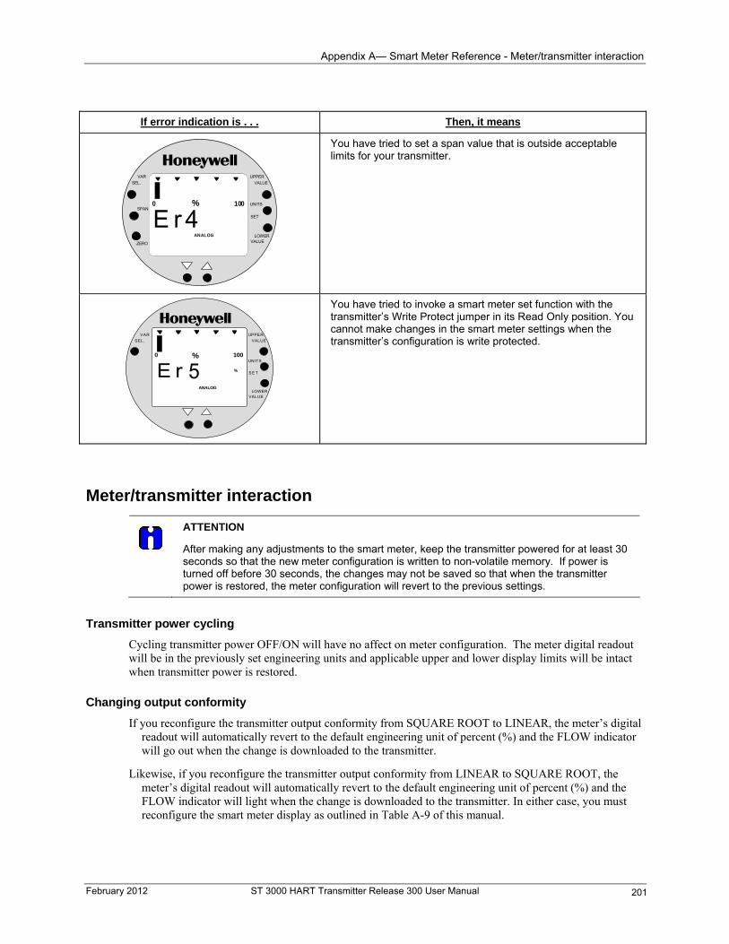
Appendix A— Smart Meter Reference - Meter/transmitter interaction
If error indication is . . . Then, it means
You have tried to set a span value that is outside acceptable limits for your transmitter.
UPPER
VALUE
UNITS
LOWERVALUE
SET
VAR
SEL.
SPAN
ZERO
% 1000
ANALOG
E r 4
% 1000
E rANALOG
%5
UPPER
VALUE
UNITS
LOWERVALUE
S E T
VAR
SEL.
You have tried to invoke a smart meter set function with the transmitter’s Write Protect jumper in its Read Only position. You cannot make changes in the smart meter settings when the transmitter’s configuration is write protected.
Meter/transmitter interaction
ATTENTION
After making any adjustments to the smart meter, keep the transmitter powered for at least 30 seconds so that the new meter configuration is written to non-volatile memory. If power is turned off before 30 seconds, the changes may not be saved so that when the transmitter power is restored, the meter configuration will revert to the previous settings.
Transmitter power cycling
Cycling transmitter power OFF/ON will have no affect on meter configuration. The meter digital readout will be in the previously set engineering units and applicable upper and lower display limits will be intact when transmitter power is restored.
Changing output conformity
If you reconfigure the transmitter output conformity from SQUARE ROOT to LINEAR, the meter’s digital readout will automatically revert to the default engineering unit of percent (%) and the FLOW indicator will go out when the change is downloaded to the transmitter.
Likewise, if you reconfigure the transmitter output conformity from LINEAR to SQUARE ROOT, the meter’s digital readout will automatically revert to the default engineering unit of percent (%) and the FLOW indicator will light when the change is downloaded to the transmitter. In either case, you must reconfigure the smart meter display as outlined in Table A-9 of this manual.
February 2012 ST 3000 HART Transmitter Release 300 User Manual 201

- Meter/transmitter interaction
ST 3000 HART Transmitter Release 300 User Manual February 2012 202
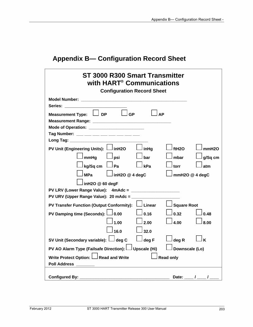
Appendix B— Configuration Record Sheet -
Appendix B— Configuration Record Sheet
ST 3000 R300 Smart Transmitter with HART Communications
Configuration Record Sheet
Model Number: ______________________________________________
Series: ___________________________
Measurement Type: DP GP AP
Measurement Range: __________________________________
Mode of Operation: ________________________
Tag Number: ___ ___ ___ ___ ___ ___ ___ ___
Long Tag: __________________________________
PV Unit (Engineering Units): inH2O inHg ftH2O mmH2O
mmHg psi bar mbar g/Sq cm
kg/Sq cm Pa kPa torr atm
MPa inH2O @ 4 degC mmH2O @ 4 degC
inH2O @ 60 degF
PV LRV (Lower Range Value): 4mAdc = _____________________
PV URV (Upper Range Value): 20 mAdc = _____________________
PV Transfer Function (Output Conformity): Linear Square Root
PV Damping time (Seconds): 0.00 0.16 0.32 0.48
1.00 2.00 4.00 8.00
16.0 32.0
SV Unit (Secondary variable): deg C deg F deg R K
PV AO Alarm Type (Failsafe Direction): Upscale (Hi) Downscale (Lo)
Write Protect Option: Read and Write Read only
Poll Address ________
Configured By: _______________________________________ Date: ____ / ____ / ____
February 2012 ST 3000 HART Transmitter Release 300 User Manual 203

-
ST 3000 HART Transmitter Release 300 User Manual February 2012 204
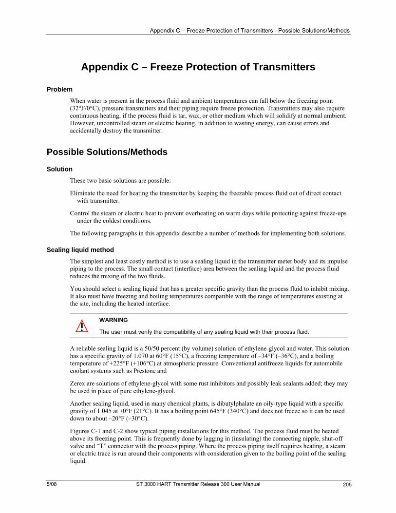
Appendix C – Freeze Protection of Transmitters - Possible Solutions/Methods
Appendix C – Freeze Protection of Transmitters
Problem
When water is present in the process fluid and ambient temperatures can fall below the freezing point (32°F/0°C), pressure transmitters and their piping require freeze protection. Transmitters may also require continuous heating, if the process fluid is tar, wax, or other medium which will solidify at normal ambient. However, uncontrolled steam or electric heating, in addition to wasting energy, can cause errors and accidentally destroy the transmitter.
Possible Solutions/Methods
Solution
These two basic solutions are possible:
Eliminate the need for heating the transmitter by keeping the freezable process fluid out of direct contact with transmitter.
Control the steam or electric heat to prevent overheating on warm days while protecting against freeze-ups under the coldest conditions.
The following paragraphs in this appendix describe a number of methods for implementing both solutions.
Sealing liquid method
The simplest and least costly method is to use a sealing liquid in the transmitter meter body and its impulse piping to the process. The small contact (interface) area between the sealing liquid and the process fluid reduces the mixing of the two fluids.
You should select a sealing liquid that has a greater specific gravity than the process fluid to inhibit mixing. It also must have freezing and boiling temperatures compatible with the range of temperatures existing at the site, including the heated interface.
WARNING
The user must verify the compatibility of any sealing liquid with their process fluid.
A reliable sealing liquid is a 50/50 percent (by volume) solution of ethylene-glycol and water. This solution has a specific gravity of 1.070 at 60°F (15°C), a freezing temperature of –34°F (–36°C), and a boiling temperature of +225°F (+106°C) at atmospheric pressure. Conventional antifreeze liquids for automobile coolant systems such as Prestone and
Zerex are solutions of ethylene-glycol with some rust inhibitors and possibly leak sealants added; they may be used in place of pure ethylene-glycol.
Another sealing liquid, used in many chemical plants, is dibutylphalate an oily-type liquid with a specific gravity of 1.045 at 70°F (21°C). It has a boiling point 645°F (340°C) and does not freeze so it can be used down to about –20°F (–30°C).
Figures C-1 and C-2 show typical piping installations for this method. The process fluid must be heated above its freezing point. This is frequently done by lagging in (insulating) the connecting nipple, shut-off valve and “T” connector with the process piping. Where the process piping itself requires heating, a steam or electric trace is run around their components with consideration given to the boiling point of the sealing liquid.
5/08 ST 3000 HART Transmitter Release 300 User Manual 205
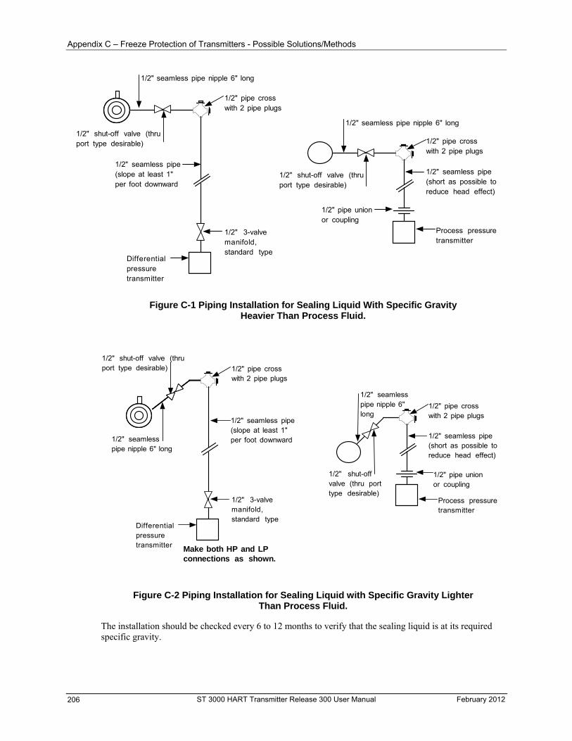
Appendix C – Freeze Protection of Transmitters - Possible Solutions/Methods
1/2" seamless pipe nipple 6" long
1/2" shut-off valve (thruport type desirable)
1/2" pipe crosswith 2 pipe plugs
1/2" seamless pipe(slope at least 1"per foot downward
1/2" 3-valvemanifold,standard type
1/2" seamless pipe(short as possible toreduce head effect)
Differentialpressuretransmitter
Process pressuretransmitter
1/2" pipe unionor coupling
1/2" pipe crosswith 2 pipe plugs
1/2" shut-off valve (thruport type desirable)
1/2" seamless pipe nipple 6" long
Figure C-1 Piping Installation for Sealing Liquid With Specific Gravity Heavier Than Process Fluid.
1/2" seamlesspipe nipple 6" long
1/2" shut-off valve (thruport type desirable)
1/2" seamless pipe(short as possible toreduce head effect)
Process pressuretransmitter
1/2" pipe unionor coupling
1/2" pipe crosswith 2 pipe plugs
1/2" shut-offvalve (thru porttype desirable)
1/2" seamlesspipe nipple 6"long
1/2" pipe crosswith 2 pipe plugs
1/2" 3-valvemanifold,standard type
Differentialpressuretransmitter
1/2" seamless pipe(slope at least 1"per foot downward
Make both HP and LPconnections as shown.
Figure C-2 Piping Installation for Sealing Liquid with Specific Gravity Lighter Than Process Fluid.
The installation should be checked every 6 to 12 months to verify that the sealing liquid is at its required specific gravity.
ST 3000 HART Transmitter Release 300 User Manual February 2012 206
Appendix C – Freeze Protection of Transmitters - Possible Solutions/Methods
Purging
Purging air or water purges are commonly used to prevent viscous materials from clogging the impulse lines to pressure, level, or flow transmitters. The bubbler system, using a constant-air flow regulator, is particularly common on open tank liquid level applications. No heating of impulse lines or transmitter is required, but normal precautions are required to keep water out of the air supply system.
Gas applications
We must not overlook the possibility of condensate freezing in impulse lines to transmitters measuring gas flow or pressure. Although these components could be heated similar to water and steam applications, the simplest and best approach is to install transmitters so that they are self draining. This means that the impulse lines are connected to the lowest point in the transmitter meter body and the piping is sloped downward at least one inch per foot. (Side-connected transmitters with vent-drains at a lower point in the meter body must be regularly checked to assure condensate removal.) If the transmitter is located below the process taps (not recommended), piping must still run downward from the transmitter to the drain point and then up to the process as shown in Figure C-3. Steam or electric heating of the drain point will prevent pipe rupture due to freezing.
Transmitter
Figure C-3 Piping Installation for Gas Flow.
Mechanical (diaphragm) seals
Diaphragm seals on the impulse lines provide the most expensive, yet broadest application of all the methods. Similar in principle to the liquid seals, diaphragm seals eliminate the possibility of seal liquid carry-over into the process fluid. This eliminates the need for periodic maintenance checks to assure full and equal liquid seal legs. Welded diaphragm seals with special fills permit temperatures from –34° to 600°F (–36° to 315°C) at the process interface which can therefore be steam or electrically heated to assure viscosity of tars and similar high-freezing point fluids under the coldest conditions.
You must be careful to specify large enough diaphragms to accommodate expansion and contraction of the fill fluid under varying temperatures without overextending the diaphragm into its stiff area. In general, conventional diaphragm seals are satisfactory for pressure ranges above approximately 75 psig with special large diameter elements required for low pressure or differential pressure measurements.
You can lag (insulate) impulse lines and diaphragm seals with the process piping, but this practice is only common with liquid level applications involving highly viscous materials unsuitable for 1/2-inch impulse
February 2012 ST 3000 HART Transmitter Release 300 User Manual 207
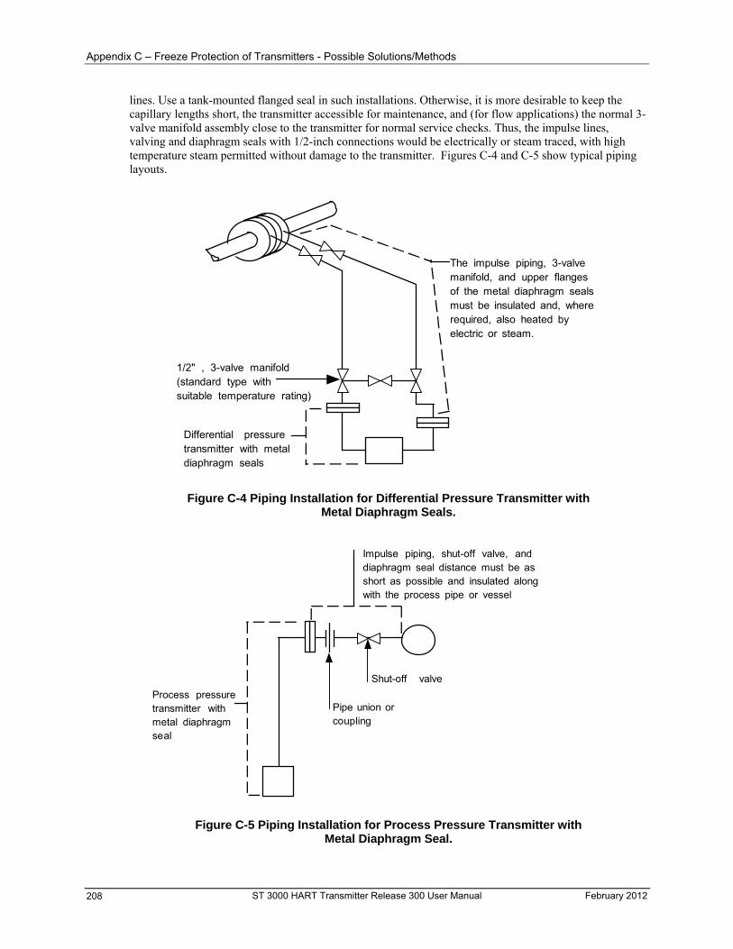
Appendix C – Freeze Protection of Transmitters - Possible Solutions/Methods
lines. Use a tank-mounted flanged seal in such installations. Otherwise, it is more desirable to keep the capillary lengths short, the transmitter accessible for maintenance, and (for flow applications) the normal 3-valve manifold assembly close to the transmitter for normal service checks. Thus, the impulse lines, valving and diaphragm seals with 1/2-inch connections would be electrically or steam traced, with high temperature steam permitted without damage to the transmitter. Figures C-4 and C-5 show typical piping layouts.
The impulse piping, 3-valvemanifold, and upper flangesof the metal diaphragm sealsmust be insulated and, whererequired, also heated byelectric or steam.
1/2" , 3-valve manifold(standard type withsuitable temperature rating)
Differential pressuretransmitter with metaldiaphragm seals
Figure C-4 Piping Installation for Differential Pressure Transmitter with Metal Diaphragm Seals.
Process pressuretransmitter withmetal diaphragmseal
Pipe union orcoupling
Shut-off valve
Impulse piping, shut-off valve, anddiaphragm seal distance must be asshort as possible and insulated alongwith the process pipe or vessel
Figure C-5 Piping Installation for Process Pressure Transmitter with Metal Diaphragm Seal.
ST 3000 HART Transmitter Release 300 User Manual February 2012 208
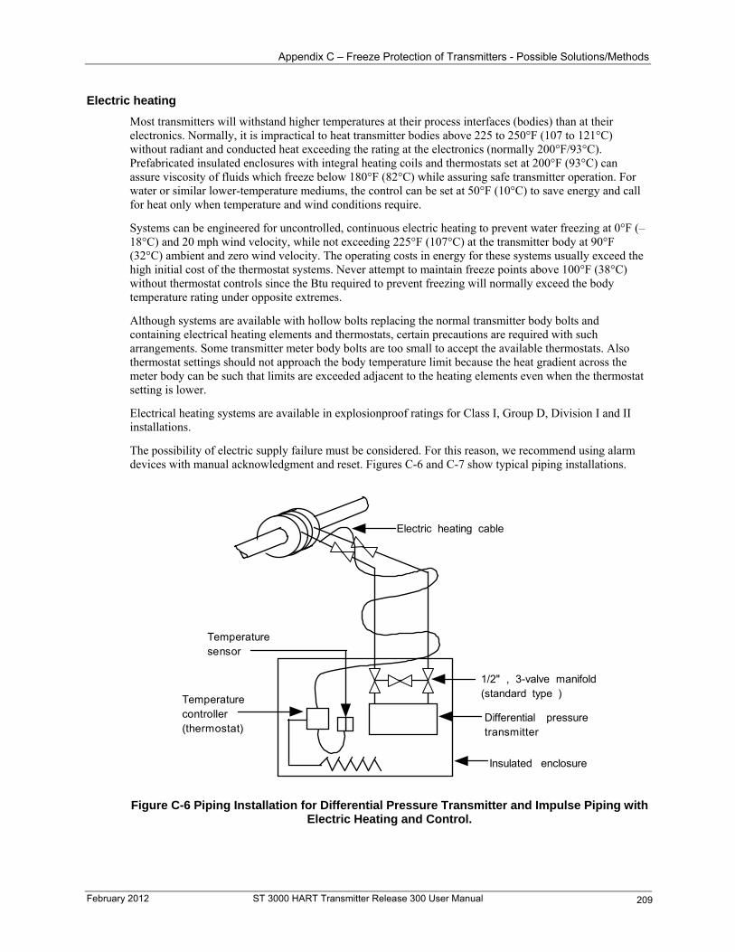
Appendix C – Freeze Protection of Transmitters - Possible Solutions/Methods
Electric heating
Most transmitters will withstand higher temperatures at their process interfaces (bodies) than at their electronics. Normally, it is impractical to heat transmitter bodies above 225 to 250°F (107 to 121°C) without radiant and conducted heat exceeding the rating at the electronics (normally 200°F/93°C). Prefabricated insulated enclosures with integral heating coils and thermostats set at 200°F (93°C) can assure viscosity of fluids which freeze below 180°F (82°C) while assuring safe transmitter operation. For water or similar lower-temperature mediums, the control can be set at 50°F (10°C) to save energy and call for heat only when temperature and wind conditions require.
Systems can be engineered for uncontrolled, continuous electric heating to prevent water freezing at 0°F (–18°C) and 20 mph wind velocity, while not exceeding 225°F (107°C) at the transmitter body at 90°F (32°C) ambient and zero wind velocity. The operating costs in energy for these systems usually exceed the high initial cost of the thermostat systems. Never attempt to maintain freeze points above 100°F (38°C) without thermostat controls since the Btu required to prevent freezing will normally exceed the body temperature rating under opposite extremes.
Although systems are available with hollow bolts replacing the normal transmitter body bolts and containing electrical heating elements and thermostats, certain precautions are required with such arrangements. Some transmitter meter body bolts are too small to accept the available thermostats. Also thermostat settings should not approach the body temperature limit because the heat gradient across the meter body can be such that limits are exceeded adjacent to the heating elements even when the thermostat setting is lower.
Electrical heating systems are available in explosionproof ratings for Class I, Group D, Division I and II installations.
The possibility of electric supply failure must be considered. For this reason, we recommend using alarm devices with manual acknowledgment and reset. Figures C-6 and C-7 show typical piping installations.
Electric heating cable
1/2" , 3-valve manifold(standard type )
Differential pressuretransmitter
Temperaturecontroller(thermostat)
Temperaturesensor
Insulated enclosure
Figure C-6 Piping Installation for Differential Pressure Transmitter and Impulse Piping with Electric Heating and Control.
February 2012 ST 3000 HART Transmitter Release 300 User Manual 209
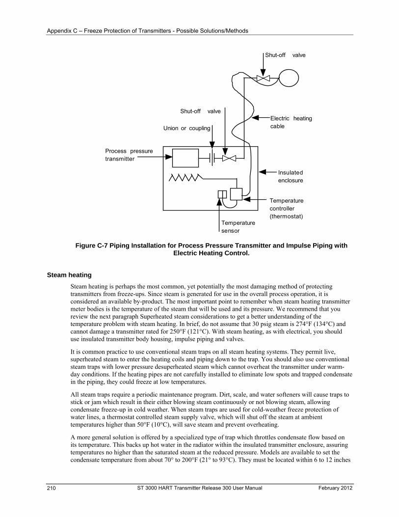
Appendix C – Freeze Protection of Transmitters - Possible Solutions/Methods
Union or coupling
Process pressuretransmitter
Temperaturecontroller(thermostat)
Temperaturesensor
Insulatedenclosure
Shut-off valve
Shut-off valveElectric heatingcable
Figure C-7 Piping Installation for Process Pressure Transmitter and Impulse Piping with Electric Heating Control.
Steam heating
Steam heating is perhaps the most common, yet potentially the most damaging method of protecting transmitters from freeze-ups. Since steam is generated for use in the overall process operation, it is considered an available by-product. The most important point to remember when steam heating transmitter meter bodies is the temperature of the steam that will be used and its pressure. We recommend that you review the next paragraph Superheated steam considerations to get a better understanding of the temperature problem with steam heating. In brief, do not assume that 30 psig steam is 274°F (134°C) and cannot damage a transmitter rated for 250°F (121°C). With steam heating, as with electrical, you should use insulated transmitter body housing, impulse piping and valves.
It is common practice to use conventional steam traps on all steam heating systems. They permit live, superheated steam to enter the heating coils and piping down to the trap. You should also use conventional steam traps with lower pressure desuperheated steam which cannot overheat the transmitter under warm-day conditions. If the heating pipes are not carefully installed to eliminate low spots and trapped condensate in the piping, they could freeze at low temperatures.
All steam traps require a periodic maintenance program. Dirt, scale, and water softeners will cause traps to stick or jam which result in their either blowing steam continuously or not blowing steam, allowing condensate freeze-up in cold weather. When steam traps are used for cold-weather freeze protection of water lines, a thermostat controlled steam supply valve, which will shut off the steam at ambient temperatures higher than 50°F (10°C), will save steam and prevent overheating.
A more general solution is offered by a specialized type of trap which throttles condensate flow based on its temperature. This backs up hot water in the radiator within the insulated transmitter enclosure, assuring temperatures no higher than the saturated steam at the reduced pressure. Models are available to set the condensate temperature from about 70° to 200°F (21° to 93°C). They must be located within 6 to 12 inches
ST 3000 HART Transmitter Release 300 User Manual February 2012 210
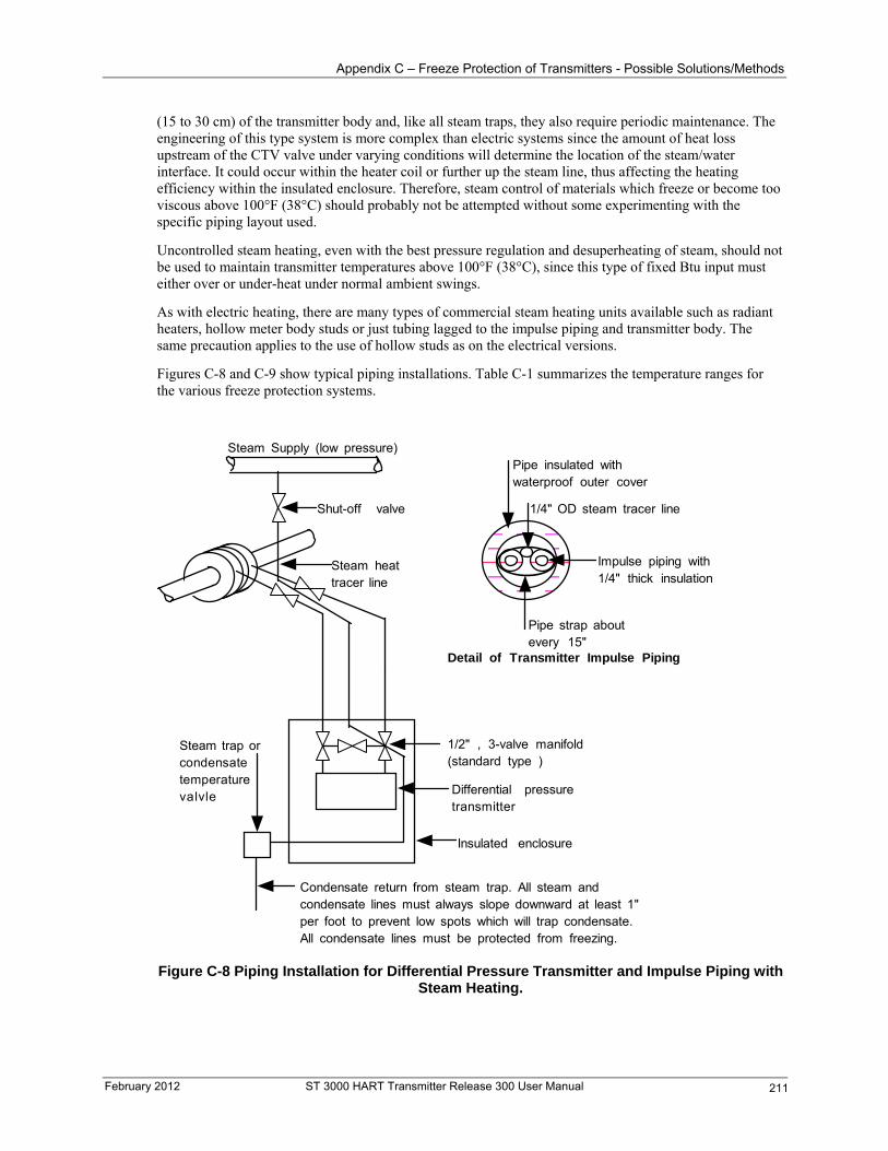
Appendix C – Freeze Protection of Transmitters - Possible Solutions/Methods
(15 to 30 cm) of the transmitter body and, like all steam traps, they also require periodic maintenance. The engineering of this type system is more complex than electric systems since the amount of heat loss upstream of the CTV valve under varying conditions will determine the location of the steam/water interface. It could occur within the heater coil or further up the steam line, thus affecting the heating efficiency within the insulated enclosure. Therefore, steam control of materials which freeze or become too viscous above 100°F (38°C) should probably not be attempted without some experimenting with the specific piping layout used.
Uncontrolled steam heating, even with the best pressure regulation and desuperheating of steam, should not be used to maintain transmitter temperatures above 100°F (38°C), since this type of fixed Btu input must either over or under-heat under normal ambient swings.
As with electric heating, there are many types of commercial steam heating units available such as radiant heaters, hollow meter body studs or just tubing lagged to the impulse piping and transmitter body. The same precaution applies to the use of hollow studs as on the electrical versions.
Figures C-8 and C-9 show typical piping installations. Table C-1 summarizes the temperature ranges for the various freeze protection systems.
Steam heattracer line
1/2" , 3-valve manifold(standard type )
Differential pressuretransmitter
Condensate return from steam trap. All steam andcondensate lines must always slope downward at least 1"per foot to prevent low spots which will trap condensate.All condensate lines must be protected from freezing.
Steam trap orcondensatetemperaturevalvle
Insulated enclosure
1/4" OD steam tracer line
Impulse piping with1/4" thick insulation
Pipe insulated withwaterproof outer cover
Pipe strap aboutevery 15"
Detail of Transmitter Impulse Piping
Shut-off valve
Steam Supply (low pressure)
Figure C-8 Piping Installation for Differential Pressure Transmitter and Impulse Piping with Steam Heating.
February 2012 ST 3000 HART Transmitter Release 300 User Manual 211
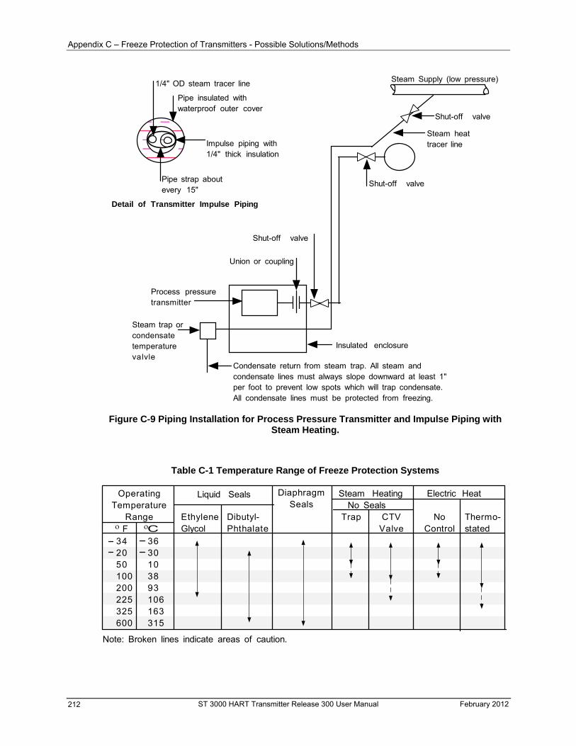
Appendix C – Freeze Protection of Transmitters - Possible Solutions/Methods
1/4" OD steam tracer line
Impulse piping with1/4" thick insulation
Pipe insulated withwaterproof outer cover
Pipe strap aboutevery 15"
Detail of Transmitter Impulse Piping
Condensate return from steam trap. All steam andcondensate lines must always slope downward at least 1"per foot to prevent low spots which will trap condensate.All condensate lines must be protected from freezing.
Steam trap orcondensatetemperaturevalvle
Insulated enclosure
Shut-off valve
Steam Supply (low pressure)
Union or coupling
Process pressuretransmitter
Shut-off valve
Shut-off valve
Steam heattracer line
Figure C-9 Piping Installation for Process Pressure Transmitter and Impulse Piping with Steam Heating.
Table C-1 Temperature Range of Freeze Protection Systems
OperatingTemperature
Range
Liquid Seals
EthyleneGlycol
Dibutyl-Phthalate
Steam HeatingNo Seals
Trap CTVValve
Electric Heat
NoControl
Thermo-statedF C
342050100200225325600
3630103893106163315
Note: Broken lines indicate areas of caution.
DiaphragmSeals
ST 3000 HART Transmitter Release 300 User Manual February 2012 212
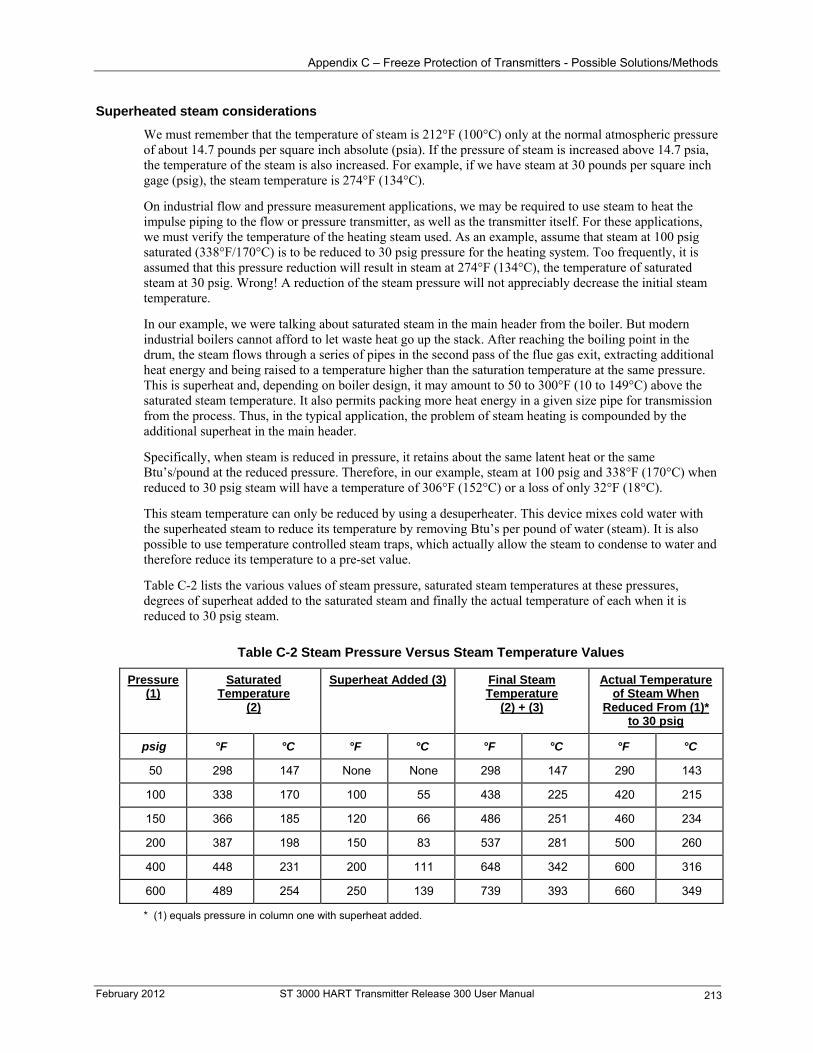
Appendix C – Freeze Protection of Transmitters - Possible Solutions/Methods
Superheated steam considerations
We must remember that the temperature of steam is 212°F (100°C) only at the normal atmospheric pressure of about 14.7 pounds per square inch absolute (psia). If the pressure of steam is increased above 14.7 psia, the temperature of the steam is also increased. For example, if we have steam at 30 pounds per square inch gage (psig), the steam temperature is 274°F (134°C).
On industrial flow and pressure measurement applications, we may be required to use steam to heat the impulse piping to the flow or pressure transmitter, as well as the transmitter itself. For these applications, we must verify the temperature of the heating steam used. As an example, assume that steam at 100 psig saturated (338°F/170°C) is to be reduced to 30 psig pressure for the heating system. Too frequently, it is assumed that this pressure reduction will result in steam at 274°F (134°C), the temperature of saturated steam at 30 psig. Wrong! A reduction of the steam pressure will not appreciably decrease the initial steam temperature.
In our example, we were talking about saturated steam in the main header from the boiler. But modern industrial boilers cannot afford to let waste heat go up the stack. After reaching the boiling point in the drum, the steam flows through a series of pipes in the second pass of the flue gas exit, extracting additional heat energy and being raised to a temperature higher than the saturation temperature at the same pressure. This is superheat and, depending on boiler design, it may amount to 50 to 300°F (10 to 149°C) above the saturated steam temperature. It also permits packing more heat energy in a given size pipe for transmission from the process. Thus, in the typical application, the problem of steam heating is compounded by the additional superheat in the main header.
Specifically, when steam is reduced in pressure, it retains about the same latent heat or the same Btu’s/pound at the reduced pressure. Therefore, in our example, steam at 100 psig and 338°F (170°C) when reduced to 30 psig steam will have a temperature of 306°F (152°C) or a loss of only 32°F (18°C).
This steam temperature can only be reduced by using a desuperheater. This device mixes cold water with the superheated steam to reduce its temperature by removing Btu’s per pound of water (steam). It is also possible to use temperature controlled steam traps, which actually allow the steam to condense to water and therefore reduce its temperature to a pre-set value.
Table C-2 lists the various values of steam pressure, saturated steam temperatures at these pressures, degrees of superheat added to the saturated steam and finally the actual temperature of each when it is reduced to 30 psig steam.
Table C-2 Steam Pressure Versus Steam Temperature Values
Pressure (1)
Saturated Temperature
(2)
Superheat Added (3) Final Steam Temperature
(2) + (3)
Actual Temperature of Steam When
Reduced From (1)* to 30 psig
psig °F °C °F °C °F °C °F °C
50 298 147 None None 298 147 290 143
100 338 170 100 55 438 225 420 215
150 366 185 120 66 486 251 460 234
200 387 198 150 83 537 281 500 260
400 448 231 200 111 648 342 600 316
600 489 254 250 139 739 393 660 349
* (1) equals pressure in column one with superheat added.
February 2012 ST 3000 HART Transmitter Release 300 User Manual 213

-
ST 3000 HART Transmitter Release 300 User Manual February 2012 214
Appendix D —Hazardous Area Classifications - Introduction
Appendix D —Hazardous Area Classifications
Introduction
Reference information
Information is provided to clarify the Hazardous Location installation requirements in North America and internationally. An explanation of the applicable enclosure classification systems is also provided.
North American Hazardous Location Standards
NEC and CEC electrical codes
Installation of electrical apparatus within hazardous (classified) locations of the United States is conducted under the provisions of the National Electrical Code (NEC), ANSI/NFPA 70, Article 500, and within Canada under the provisions of the Canadian Electrical Code (CEC) C22.1, Part 1, Section 18.
Classes
Hazardous (classified) locations, in both the United States and Canada, are categorized into one of three classes:
Class I - Presence of flammable gases or vapors may be present in quantities sufficient to produce explosive or ignitable mixtures
Class II - Presence of combustible dusts, powders or grains
Class III - Presence of easily ignitable fibers or flyings
Divisions
The classes listed above are further categorized based upon the level of risk present:
Division 1 - Locations in which hazardous concentrations of flammable gases or vapors - or combustible dust in suspension – are continuously, intermittently or periodically present under normal operating conditions.
Division 2 - Locations in which flammable gases or vapors are present, but normally confined within closed containers or systems from which they can escape only under abnormal or fault conditions. Combustible dusts are not normally in suspension nor likely to be thrown into suspension.
Examples
Given the criteria above, the following examples are made:
Class III, Division 1 - A class III, Division 1 location is a location in which easily ignitable fibers or material processing combustible flyings are handled, manufactured or used.
Class III, Division 2 - A Class III, Division 2 location is a location in which easily ignitable fibers are stored or handled.
February 2012 ST 3000 HART Transmitter Release 300 User Manual 215
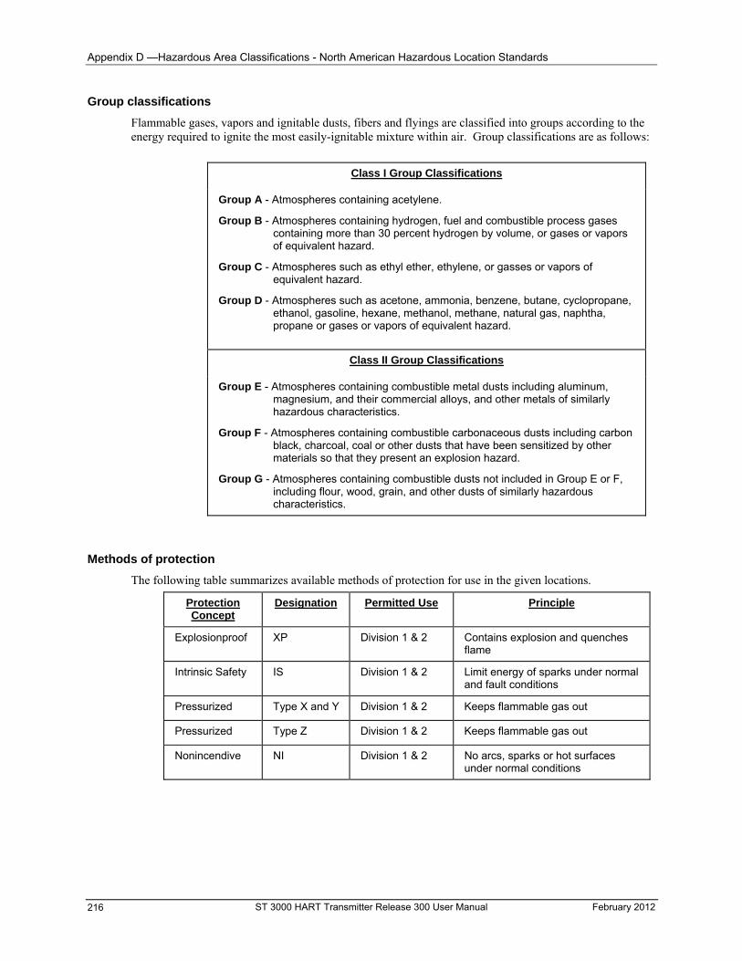
Appendix D —Hazardous Area Classifications - North American Hazardous Location Standards
Group classifications
Flammable gases, vapors and ignitable dusts, fibers and flyings are classified into groups according to the energy required to ignite the most easily-ignitable mixture within air. Group classifications are as follows:
Class I Group Classifications
Group A - Atmospheres containing acetylene. Group B - Atmospheres containing hydrogen, fuel and combustible process gases
containing more than 30 percent hydrogen by volume, or gases or vapors of equivalent hazard.
Group C - Atmospheres such as ethyl ether, ethylene, or gasses or vapors of equivalent hazard.
Group D - Atmospheres such as acetone, ammonia, benzene, butane, cyclopropane, ethanol, gasoline, hexane, methanol, methane, natural gas, naphtha, propane or gases or vapors of equivalent hazard.
Class II Group Classifications
Group E - Atmospheres containing combustible metal dusts including aluminum, magnesium, and their commercial alloys, and other metals of similarly hazardous characteristics.
Group F - Atmospheres containing combustible carbonaceous dusts including carbon black, charcoal, coal or other dusts that have been sensitized by other materials so that they present an explosion hazard.
Group G - Atmospheres containing combustible dusts not included in Group E or F, including flour, wood, grain, and other dusts of similarly hazardous characteristics.
Methods of protection
The following table summarizes available methods of protection for use in the given locations.
Protection Concept
Designation Permitted Use Principle
Explosionproof XP Division 1 & 2 Contains explosion and quenches flame
Intrinsic Safety IS Division 1 & 2 Limit energy of sparks under normal and fault conditions
Pressurized Type X and Y Division 1 & 2 Keeps flammable gas out
Pressurized Type Z Division 1 & 2 Keeps flammable gas out
Nonincendive NI Division 1 & 2 No arcs, sparks or hot surfaces under normal conditions
ST 3000 HART Transmitter Release 300 User Manual February 2012 216
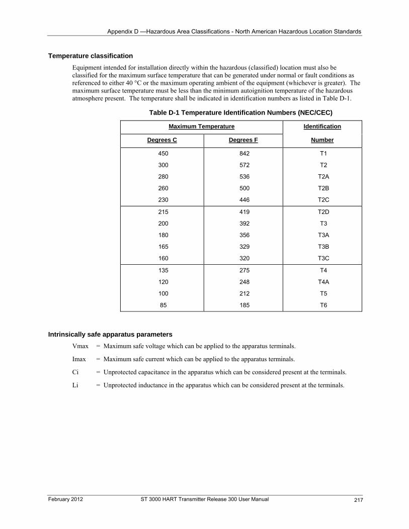
Appendix D —Hazardous Area Classifications - North American Hazardous Location Standards
Temperature classification
Equipment intended for installation directly within the hazardous (classified) location must also be classified for the maximum surface temperature that can be generated under normal or fault conditions as referenced to either 40 °C or the maximum operating ambient of the equipment (whichever is greater). The maximum surface temperature must be less than the minimum autoignition temperature of the hazardous atmosphere present. The temperature shall be indicated in identification numbers as listed in Table D-1.
Table D-1 Temperature Identification Numbers (NEC/CEC)
Maximum Temperature Identification
Degrees C Degrees F Number
450
300
280
260
230
842
572
536
500
446
T1
T2
T2A
T2B
T2C
215
200
180
165
160
419
392
356
329
320
T2D
T3
T3A
T3B
T3C
135 275 T4
120 248 T4A
100 212 T5
85 185 T6
Intrinsically safe apparatus parameters
Vmax = Maximum safe voltage which can be applied to the apparatus terminals.
Imax = Maximum safe current which can be applied to the apparatus terminals.
Ci = Unprotected capacitance in the apparatus which can be considered present at the terminals.
Li = Unprotected inductance in the apparatus which can be considered present at the terminals.
February 2012 ST 3000 HART Transmitter Release 300 User Manual 217
Appendix D —Hazardous Area Classifications - North American Hazardous Location Standards
ST 3000 HART Transmitter Release 300 User Manual February 2012 218
Associated apparatus parameters
Voc = Maximum output voltage which can be delivered to the hazardous (classified) location. This voltage is the maximum from a single channel.
Isc = Maximum output current which can be delivered to the hazardous (classified) location. This current is the maximum from a single channel.
*Vt = Maximum output voltage which can be delivered to the hazardous (classified) location. This voltage is the maximum across any combination of terminals of a multiple channel configuration.
*It = Maximum output current which can be delivered to the hazardous (classified) location. This current is the maximum through any combination of terminals of a multiple channel configuration.
Ca = Maximum capacitance which can be connected to the apparatus.
La = Maximum inductance which can be connected to the apparatus.
*CSA does not recognize these parameters at this time
Entity concept
Under entity requirements, the concept allows interconnection of intrinsically safe apparatus to associated apparatus, not specifically examined in such combination. The criteria for interconnection is that the voltage (Vmax) and current (Imax), which intrinsically safe apparatus can receive and remain intrinsically safe, considering faults, must be equal to or greater than the voltage (Voc or Vt) and current (Isc or It) levels which can be delivered by the associated apparatus, considering faults and applicable factors. In addition, the maximum unprotected capacitance (Ci) and inductance (Li) of the intrinsically safe apparatus, including interconnecting wiring, must be less than or equal to the capacitance (Ca) and inductance (La) which can be safely connected to the associated apparatus. If these criteria are met, then the combination may be connected and remain intrinsically safe. Both FMRC and CSA define the entity parameters as listed in Tables D-2, D-3 and D-4 below:
Factory Mutual (FM) Approval
Code Description
1C
Explosionproof for Class I, Division 1, Groups A, B, C & D. Dust-Ignitionproof for Class II, Division 1, Groups E, F & G. Suitable for Class III, Division 1. Conduit seals required within 18” of enclosure, Group A only.
Intrinsically Safe for use in Class I, Division 1, Groups A, B, C & D; Class II, Division 1, Groups E, F & G; Class III, Division 1, T4 at 40C, T3A at 93C maximum ambient, when connected in accordance with Honeywell drawing 51205784.
Nonincendive for use in Class I, Division 2, Groups A, B, C & D; Suitable for Classes II & III, Division 2, Groups F & G, T4 at 93C maximum ambient, hazardous locations. 42 Vdc max.
Environmental: Indoor and outdoor hazardous locations (NEMA 4X).
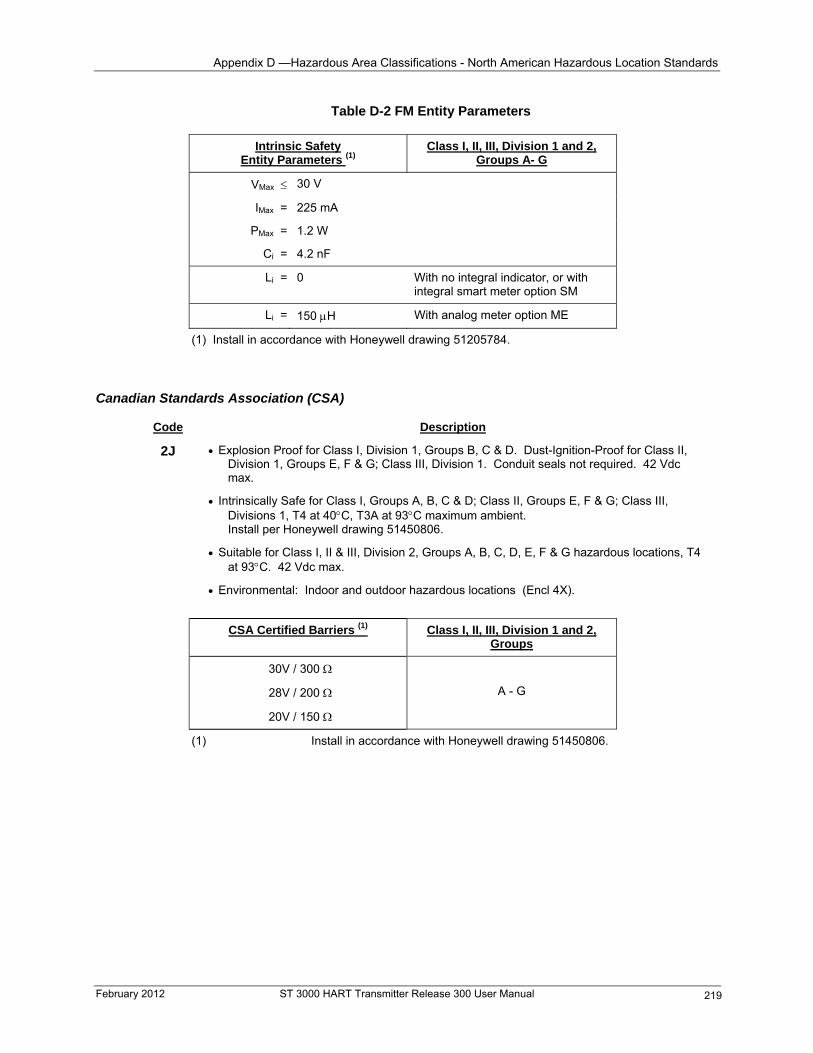
Appendix D —Hazardous Area Classifications - North American Hazardous Location Standards
February 2012 ST 3000 HART Transmitter Release 300 User Manual 219
Table D-2 FM Entity Parameters Intrinsic Safety
Entity Parameters (1) Class I, II, III, Division 1 and 2,
Groups A- G
VMax 30 V
IMax = 225 mA
PMax = 1.2 W
Ci = 4.2 nF
Li = 0 With no integral indicator, or with integral smart meter option SM
Li = 150 H With analog meter option ME
(1) Install in accordance with Honeywell drawing 51205784.
Canadian Standards Association (CSA)
Code Description
2J
Explosion Proof for Class I, Division 1, Groups B, C & D. Dust-Ignition-Proof for Class II, Division 1, Groups E, F & G; Class III, Division 1. Conduit seals not required. 42 Vdc max.
Intrinsically Safe for Class I, Groups A, B, C & D; Class II, Groups E, F & G; Class III, Divisions 1, T4 at 40C, T3A at 93C maximum ambient. Install per Honeywell drawing 51450806.
Suitable for Class I, II & III, Division 2, Groups A, B, C, D, E, F & G hazardous locations, T4 at 93C. 42 Vdc max.
Environmental: Indoor and outdoor hazardous locations (Encl 4X). CSA Certified Barriers (1) Class I, II, III, Division 1 and 2,
Groups
30V / 300
28V / 200
20V / 150
A - G
(1) Install in accordance with Honeywell drawing 51450806.
Appendix D —Hazardous Area Classifications - International Electrotechnical Commission (IEC) Classifications
International Electrotechnical Commission (IEC) Classifications
IEC Classification of hazardous locations
The IEC has established a number of recommendations applying to the construction of explosion protected electrical apparatus identified. These recommendations are found within IEC 79-0 through 79-15 and 79-28.
For all EC countries as well as various neighboring countries (CENELEC member states), the European Standards EN 50 014 to EN 50 020 and EN 50 039 apply for the construction of explosion protected electrical apparatus. They were established on the basis of the IEC Recommendations, however in comparison they are much more detailed.
Zones
Defined within IEC 7-10, Hazardous locations are categorized into three zones:
Zone 0 - Explosive gas atmosphere is present continuously, or is present for long periods.
Zone 1 - Explosive gas atmosphere is likely to occur in normal operation.
Zone 2 - Explosive gas atmosphere is not likely to occur in normal operation and, if it does occur, it will exist for a short period only.
Groups
Flammable gases, vapors and mists are classified into groups according to the energy required to ignite the most easily ignitable mixture within air. Apparatus is grouped according to the atmospheres it may be used within as follows:
Group IIC - Atmospheres containing acetylene, hydrogen, fuel and combustible process gases or vapors of equivalent hazard.
Group IIB - Atmospheres such as ethyl ether, ethylene, or gasses or vapors of equivalent hazard.
Group IIA - Atmospheres such as acetone, benzene, butane, cyclopropane, ethanol, gasoline, hexane, methanol, methane, natural gas, naphtha, propane or gases or vapors of equivalent hazard.
ST 3000 HART Transmitter Release 300 User Manual February 2012 220
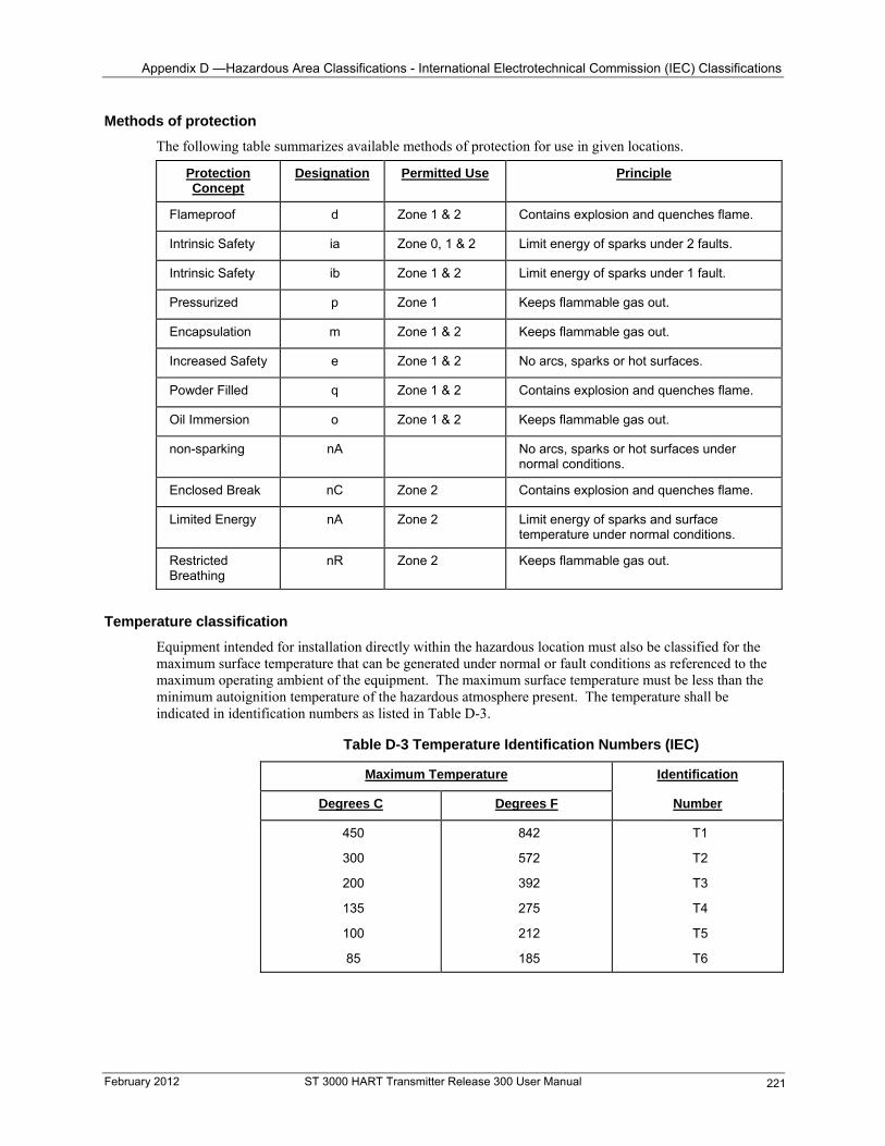
Appendix D —Hazardous Area Classifications - International Electrotechnical Commission (IEC) Classifications
Methods of protection
The following table summarizes available methods of protection for use in given locations.
Protection Concept
Designation Permitted Use Principle
Flameproof d Zone 1 & 2 Contains explosion and quenches flame.
Intrinsic Safety ia Zone 0, 1 & 2 Limit energy of sparks under 2 faults.
Intrinsic Safety ib Zone 1 & 2 Limit energy of sparks under 1 fault.
Pressurized p Zone 1 Keeps flammable gas out.
Encapsulation m Zone 1 & 2 Keeps flammable gas out.
Increased Safety e Zone 1 & 2 No arcs, sparks or hot surfaces.
Powder Filled q Zone 1 & 2 Contains explosion and quenches flame.
Oil Immersion o Zone 1 & 2 Keeps flammable gas out.
non-sparking nA No arcs, sparks or hot surfaces under normal conditions.
Enclosed Break nC Zone 2 Contains explosion and quenches flame.
Limited Energy nA Zone 2 Limit energy of sparks and surface temperature under normal conditions.
Restricted Breathing
nR Zone 2 Keeps flammable gas out.
Temperature classification
Equipment intended for installation directly within the hazardous location must also be classified for the maximum surface temperature that can be generated under normal or fault conditions as referenced to the maximum operating ambient of the equipment. The maximum surface temperature must be less than the minimum autoignition temperature of the hazardous atmosphere present. The temperature shall be indicated in identification numbers as listed in Table D-3.
Table D-3 Temperature Identification Numbers (IEC)
Maximum Temperature Identification
Degrees C Degrees F Number
450
300
200
135
842
572
392
275
100 212
185
T1
T2
T3
T4
T5
85 T6
February 2012 ST 3000 HART Transmitter Release 300 User Manual 221
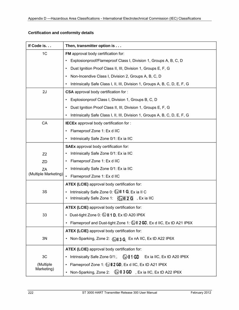
Appendix D —Hazardous Area Classifications - International Electrotechnical Commission (IEC) Classifications
Certification and conformity details
If Code is. . . Then, transmitter option is . . .
1C FM approval body certification for:
• Explosionproof/Flameproof Class I, Division 1, Groups A, B, C, D
• Dust Ignition Proof Class II, III, Division 1, Groups E, F, G
• Non-Incendive Class I, Division 2, Groups A, B, C, D
• Intrinsically Safe Class I, II, III, Division 1, Groups A, B, C, D, E, F, G
2J CSA approval body certification for :
• Explosionproof Class I, Division 1, Groups B, C, D
• Dust Ignition Proof Class II, III, Division 1, Groups E, F, G
• Intrinsically Safe Class I, II, III, Division 1, Groups A, B, C, D, E, F, G
CA IECEx approval body certification for :
• Flameproof Zone 1: Ex d IIC
• Intrinsically Safe Zone 0/1: Ex ia IIC
Z2
ZD
ZA (Multiple Marketing)
SAEx approval body certification for:
• Intrinsically Safe Zone 0/1: Ex ia IIC
• Flameproof Zone 1: Ex d IIC
• Intrinsically Safe Zone 0/1: Ex ia IIC
• Flameproof Zone 1: Ex d IIC
3S
ATEX (LCIE) approval body certification for:
• Intrinsically Safe Zone 0: , Ex ia II C
• Intrinsically Safe Zone 1: , Ex ia IIC
33
ATEX (LCIE) approval body certification for:
• Dust-tight Zone 0: , Ex tD A20 IP6X
• Flameproof and Dust-tight Zone 1: , Ex d IIC, Ex tD A21 IP6X
3N
ATEX (LCIE) approval body certification for:
• Non-Sparking, Zone 2: , Ex nA IIC, Ex tD A22 IP6X
ATEX (LCIE) approval body certification for:
• Intrinsically Safe Zone 0/1:, Ex ia IIC, Ex tD A20 IP6X 3C
(Multiple Marketing)
• Flameproof Zone 1: , Ex d IIC, Ex tD A21 IP6X
• Non-Sparking, Zone 2: , Ex ia IIC, Ex tD A22 IP6X
ST 3000 HART Transmitter Release 300 User Manual February 2012 222

Appendix D —Hazardous Area Classifications - International Electrotechnical Commission (IEC) Classifications
CERTUSP INMETRO (Brazil) approval body certification for:
• Flameproof Zone 1: BR-Ex d IIC 6D
• Intrinsically Safe Zone 0/1: BR-Ex ia IIC 6S
9X No certification
February 2012 ST 3000 HART Transmitter Release 300 User Manual 223
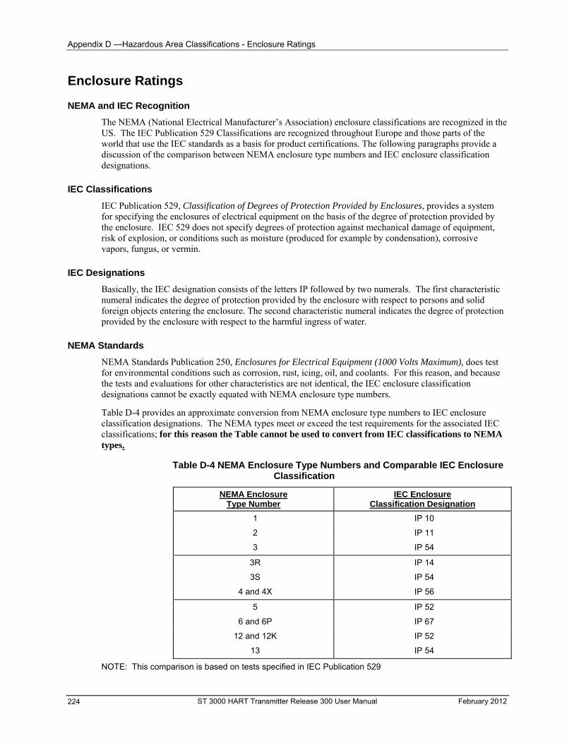
Appendix D —Hazardous Area Classifications - Enclosure Ratings
Enclosure Ratings
NEMA and IEC Recognition
The NEMA (National Electrical Manufacturer’s Association) enclosure classifications are recognized in the US. The IEC Publication 529 Classifications are recognized throughout Europe and those parts of the world that use the IEC standards as a basis for product certifications. The following paragraphs provide a discussion of the comparison between NEMA enclosure type numbers and IEC enclosure classification designations.
IEC Classifications
IEC Publication 529, Classification of Degrees of Protection Provided by Enclosures, provides a system for specifying the enclosures of electrical equipment on the basis of the degree of protection provided by the enclosure. IEC 529 does not specify degrees of protection against mechanical damage of equipment, risk of explosion, or conditions such as moisture (produced for example by condensation), corrosive vapors, fungus, or vermin.
IEC Designations
Basically, the IEC designation consists of the letters IP followed by two numerals. The first characteristic numeral indicates the degree of protection provided by the enclosure with respect to persons and solid foreign objects entering the enclosure. The second characteristic numeral indicates the degree of protection provided by the enclosure with respect to the harmful ingress of water.
NEMA Standards
NEMA Standards Publication 250, Enclosures for Electrical Equipment (1000 Volts Maximum), does test for environmental conditions such as corrosion, rust, icing, oil, and coolants. For this reason, and because the tests and evaluations for other characteristics are not identical, the IEC enclosure classification designations cannot be exactly equated with NEMA enclosure type numbers.
Table D-4 provides an approximate conversion from NEMA enclosure type numbers to IEC enclosure classification designations. The NEMA types meet or exceed the test requirements for the associated IEC classifications; for this reason the Table cannot be used to convert from IEC classifications to NEMA types.
Table D-4 NEMA Enclosure Type Numbers and Comparable IEC Enclosure Classification
NEMA Enclosure Type Number
IEC Enclosure Classification Designation
1 IP 10
2 IP 11
3 IP 54
3R IP 14
3S IP 54
4 and 4X IP 56
5 IP 52
6 and 6P IP 67
12 and 12K IP 52
13 IP 54
NOTE: This comparison is based on tests specified in IEC Publication 529
ST 3000 HART Transmitter Release 300 User Manual February 2012 224
- Process Sealing for Classes I, II, and III, Divisions 1 and 2 and Class I, Zone 0, 1, and 2, Explosionproof Electrical Systems
Process Sealing for Classes I, II, and III, Divisions 1 and 2 and Class I, Zone 0, 1, and 2, Explosionproof Electrical Systems
ST 3000, Smart Pressure Transmitters
The ST 3000, Series 100, 100e, 600, and 900, Smart Pressure Transmitters are CSA certified as “Dual Seal” devices in accordance with ANSI/ISA–12.27.01–2003, Requirements for Process Sealing between Electrical Systems and Flammable or Combustible Process Fluids.
Accordingly, the ST 3000, Series 100, 100e, 600, and 900, Smart Pressure Transmitters comply with the sealing requirements of NEC Chapter 5. Special Occupancies, Article 500 — Hazardous (Classified) Locations, Classes I, II, and III, Divisions 1 and 2, Article 501 — Class I Locations, Article 501-15, Sealing and Drainage, (f) Drainage, (3) Canned Pumps, Process or Service Connections, Etc., Article 505 — Class I, Zone 0, 1, and 2 Locations, Article 505-16, Sealing and Drainage, (E) Drainage, (3) Canned Pumps, Process, or Service Connections, and So Forth., and the Canadian Electrical Code rules 18-092, 18-108, 18-158, J18-108 and J18-158.
Annunciation of a primary seal failure per ANSI/ISA–12.27.01 is electronic and is displayed in various forms based on the type of communication used for the particular transmitter. Failure of the primary seal is considered a Critical Failure. Based on testing annunciation of primary seal failure will occur in 7 hours or less.
The transmitter’s 4-20 mA output will be driven to the selected failsafe direction – upscale or downscale.
The transmitter’s digital output (DE, HART, Fieldbus) will display any of the following responses which could indicate a primary seal failure as well as other meter body faults.
METER BODY FAULT, MB OVERLOAD, SUSPECT INPUT, SENSOR FAILURE, DEVICE FAILURE.
February 2012 ST 3000 HART Transmitter Release 300 User Manual 225

-
ST 3000 HART Transmitter Release 300 User Manual February 2012 226
Index -
February 2012 ST 3000 HART Transmitter Release 300 User Manual 227
Index
A Analog meter connections, 38 Approvals, 36
Canadian Standards Association (CSA), 183 Factory Mutual (FM), 182
B Barrier diaphragms, 127
inspecting and cleaning, 127
C Calibration
analog output signal, 138 range, 139 reset, 142
Certification CENELEC / LCIE, 186 Standards Australia (LOSC), 186 Zone 2 (Europe) Declaration of Conformity, 187
Communication errors, 148 Communications
request/response format, 7 starting, 44 transmitter/communicator, 7
Communicator connections, 79 connections to transmitter, 43 disconnecting, 75 keyboard, 58 memory module or data pack, 49 Software compatibility, 41 viewing/entering device information, 68
Configuration device information, 68 LRV and URV, 66 PV damping, 72 PV engineering units, 65 PV transfer function (output conformity), 70 SV units (meter body temperature), 73 tag number, 64
Configuration data reviewing, 45
Configuration database, 49 Configuration parameter summary, 51 Constant-current source mode, 78 Critical failures
clearing critical failures, 151
D Damping time, 72
adjusting, 72 Damping Time Constant, 52 Database
save/restore, 109 Device Information, 52 Diagnostic messages, 146
communication errors, 146 critical failures, 146 non-critical failures, 146
Diaphragm seals, 171
E Electric heating, 173 Electrical codes
IEC and CENELEC, 184 NEC and CEC, 179
EMC Directive, 13 Enclosure Ratings, 187 Enclosures
IEC classification, 188 NEMA standards, 188
Engineering units, 65 pre-programmed, 65 selecting, 65
F Failsafe direction, 105 Failure mode alarm
jumper, 46 Flange adapter
installing, 33 Flange connections
description, 32 Flange mounted transmitter, 26
Mounting, 26 Flow engineering units
Smart meter, 148 Flow measurement application, 80 Freeze protection, 169
H HART 5 275 Communicator
menu summary, 55 HART 6 375 Communicator
menu summary, 57 Hazardous location installation, 37 Hazardous location requirements, 179
Index -
J Jumpers
failsafe direction, 46 repositioning procedure, 105
L Lightning Protection, 37 Liquid level measurement application, 96
differential pressure (DP), 85, 87 gauge pressure (GP), 90 remote diaphragm seals, 96
Local smart meter options, 10 Local zero and span
adjusting (procedure), 144 Loop wiring, 38 LRV, 66
keying in, 66 setting to applied pressure, 67
LRV (Lower Range Value), 51
M Maintenance routines, 127 Master reset, 151 Meter body
replacing, 133 Model number
format, 4 Mounting
suggested location, 30 Mounting area
considerations, 14 Mounting transmitter
bracket mounting, 18 flange mounting, 26 flush mounting, 24 Models STA122, STA922, 21 remote diaphragm seal mounting, 27
Multidrop mode, 52, 74
N Non-critical failures, 147 Nonvolatile memory, 49
O Operation
data access, 101 Operation data, 101
failsafe output direction, 104 input pressure, 102 message (or scratchpad) area, 104 output, 102, 103 temperature, 104 upper and lower range limits, 103
Output conformity, 52, 70 selecting, 70
Output conformity and smart meter configuration, 148 Output meter options, 38 Output mode, 78
P Parts identification, 152 Piping, 29
guidelines, 32 Poll address, 52, 74, 75 Potential noise sources, 14 Power supply voltage
operating range, 34 Pressure measurement application
absolute pressure (AP), 93 differential pressure (DP), 82 gauge pressure (GP), 90
Pressure ratings, 16 Printed Wiring Assembly (PWA)
replacing, 130 Process connections
summary, 31 Process head bolt
torque ratings, 130 PV engineering unit, 51
R Recommended spare parts, 171 Restore database, 111
S Sealing liquid, 169 SM 3000 smart meter connections, 39 Smart meter
configuration and output conformity, 148 configuration using meter pushbuttons, 147 engineering units code, 148 error codes, 165 indications, 164 meter/transmitter interaction, 166 selecting engineering units, 149 setting display of LRV (using meter pushbuttons), 151 setting display of URV (using meter pushbuttons), 155 setting display using HART communicator, 161
Smart meter display, 47 description, 141 operating conditions and specifications, 143
Smart meter option (option SM), 140 Software version compatibility, 41 Solution Support Center, iv Span, 66, 67 Square root dropout, 71 Square root output, 70 ST 3000 smart transmitter, 2
ST 3000 HART Transmitter Release 300 User Manual February 2012 228
Index -
February 2012 ST 3000 HART Transmitter Release 300 User Manual 229
Start-up, 77 AP transmitter
pressure measurement application, 93 DP transmitter
flow measurement application, 80 liquid level measurement application, 85, 87 pressure measurement application, 82
DP transmitter (remote seals) liquid level measurement application, 96
GP transmitter liquid level measurement application, 90 pressure measurement application, 90
Start-up tasks reference, 12 Static electricity damage, 105 Status, 103
clearing critical status, 151 Steam heating, 174 Superheated steam considerations, 177
T Tag number, 51, 64 Temperature Limits
Operating, 14 Three-valve manifold
piping, 29 Torque ratings, 130 Transmitter
failure mode alarm jumper, 46 mounting, 17 operating temperature limits, 14 piping, 29 pressure ratings, 16
start-up, 77 wiring, 34 write protection option, 46
Transmitter models, 5 Transmitter types, 4 Turndown Ratio, 72
U URV, 66
keying in, 66 setting to applied pressure, 67
URV (Upper Range Value), 51
V Vibration sources, 14
W Wiring transmitter
connections, 35 Working memory, 49 Write protection option, 105 Writing data in the message area, 108
Z Zero and span adjust options, 10 Zero corrects, 21 Zero shift, 21
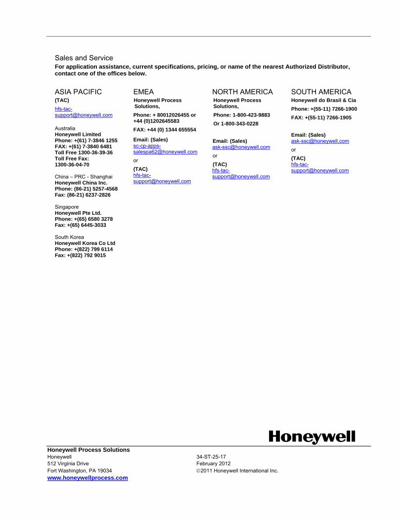
Sales and Service For application assistance, current specifications, pricing, or name of the nearest Authorized Distributor, contact one of the offices below.
ASIA PACIFIC (TAC)
Australia Honeywell Limited Phone: +(61) 7-3846 1255 FAX: +(61) 7-3840 6481 Toll Free 1300-36-39-36 Toll Free Fax: 1300-36-04-70 China – PRC - Shanghai Honeywell China Inc. Phone: (86-21) 5257-4568 Fax: (86-21) 6237-2826 Singapore Honeywell Pte Ltd. Phone: +(65) 6580 3278 Fax: +(65) 6445-3033 South Korea Honeywell Korea Co Ltd Phone: +(822) 799 6114 Fax: +(822) 792 9015
EMEA Honeywell Process Solutions,
Phone: + 80012026455 or +44 (0)1202645583
FAX: +44 (0) 1344 655554
Email: (Sales) [email protected]
or
(TAC) [email protected]
NORTH AMERICA Honeywell Process Solutions,
Phone: 1-800-423-9883
Or 1-800-343-0228
Email: (Sales) [email protected]
or
SOUTH AMERICA Honeywell do Brasil & Cia
Phone: +(55-11) 7266-1900
FAX: +(55-11) 7266-1905
Email: (Sales)
Honeywell Process Solutions Honeywell 34-ST-25-17 512 Virginia Drive February 2012 Fort Washington, PA 19034 2011 Honeywell International Inc. www.honeywellprocess.com
(TAC) [email protected]
or
(TAC) [email protected]