Embed Size (px)
Citation preview

3-Axis TB6560 CNC Driver Board User Manual - ST-6560V3
1
User's Manual For
ST-6560V3
Version 2.0
2016.08.25
All Rights Reserved
1. Key Features
Toshiba TB6560AHQ chip - High power, maximum current 3.5A
Resolution 1, 1/2, 1/8, 1/16 micro stepping output
Working voltage DC12-DC30V, rated voltage 24V
Adjustable current with 100%, 75%, 50%, 20% of full current by on-board switch.
Half current function when no signal to prevent motor heating
Build with a 227V 10A Relay
Manual Control circuit included
Overload, over-current and over-temperature safety
Protect the computer by using isolating power(1000V DC\DC) and optoelectronic coupler
Supports most parallel software MACH3, KCAM4, EMC2 etc.
Fixed in Aluminum box, better cooling function than fan and safer protection for board circuit
www.oyostepper.com

3-Axis TB6560 CNC Driver Board User Manual - ST-6560V3
2
2. Photo of 3-AXIS CNC Board
DB25 LPT
Manual control port & 4th extended
axis
Isolated power 3 axis drive module
X axis motor
12~24v Power
Signal input
Relay output
AC 277V-10A relay Relay output light
Power light
Y axis motor
Z axis motor
3 axis working light overheat warning light
Parallel signal drive &optical
coupling interface
Microstep, decay, current setting
www.oyostepper.com

3-Axis TB6560 CNC Driver Board User Manual - ST-6560V3
3
3. Hardware Installation
3.1 Selecting and Connecting Stepper Motors
WARNING: INCORRECT WIRING OF THE STEPPER MOTOR TO THE DRIVE BOARD CAN LEAD TO
IMMEDIATE DAMAGE OF DRIVE BOARD - DO NOT CONNECT OR DISCONNECT MOTORS WHILE POWER
IS ON.
4 Wire, 6 Wire, and 8 Wire stepper motors can be used.
4 Wire motors are recommended as they are by their manufacture true bipolar motors and easier
to properly connect to stepper motor drive controller.
It is critical to obtain a proper motor coil diagram of any motor you wish to utilize (making cross
connections between the two coils will destroy the control circuitry).
1.8 deg per step resolution is the industry standard for most automation grade stepper motors
and is recommended for most applications.
a. 4 Wire Stepper Diagram
Each wire is connected to its corresponding terminal block location (i.e. A- wire is connected at A-
location).
b. 6 Wire Stepper Diagram
www.oyostepper.com

3-Axis TB6560 CNC Driver Board User Manual - ST-6560V3
4
Center wire of each coil not connected (insulate termination). Remaining wires are connected to their
corresponding terminal block location (i.e. A- wire is connected at A- location).
c. 8 Wire Stepper Diagram
2 center wires of each coil connected (insulate connection)
Remaining wires are connected to their corresponding terminal block location (i.e. A- wire is connected
at A- location).
If using 6 or 8 wire motors, connected using series wiring method, reduce labeled amperage rating by 50%
(i.e. a motor rated at 4 amps should thus be considered now rated at 2 amps).
3.2 Connect to Computer by DB25
The following is to aid in the setup of the use of controller with various CAM software programs
operating on your computer.
www.oyostepper.com
3-Axis TB6560 CNC Driver Board User Manual - ST-6560V3
5
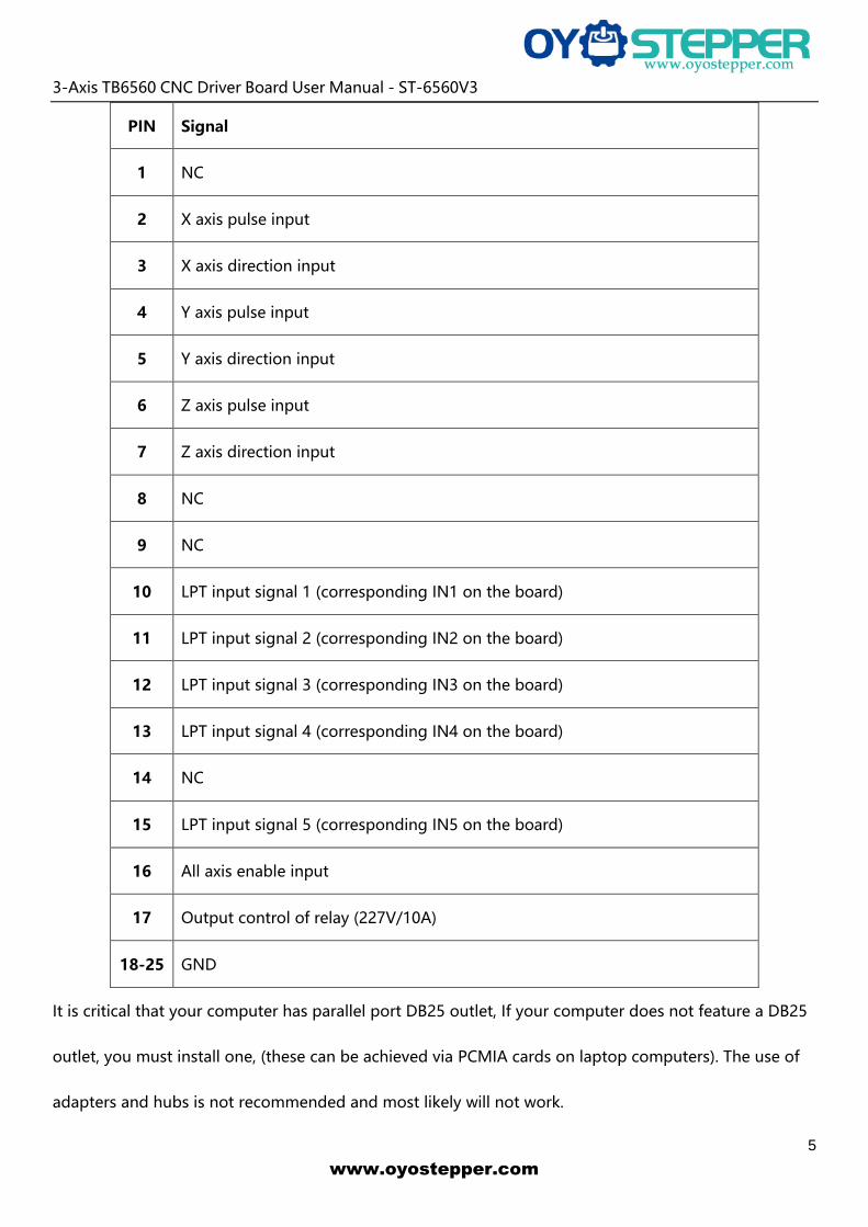
PIN Signal
1 NC
2 X axis pulse input
3 X axis direction input
4 Y axis pulse input
5 Y axis direction input
6 Z axis pulse input
7 Z axis direction input
8 NC
9 NC
10 LPT input signal 1 (corresponding IN1 on the board)
11 LPT input signal 2 (corresponding IN2 on the board)
12 LPT input signal 3 (corresponding IN3 on the board)
13 LPT input signal 4 (corresponding IN4 on the board)
14 NC
15 LPT input signal 5 (corresponding IN5 on the board)
16 All axis enable input
17 Output control of relay (227V/10A)
18-25 GND
It is critical that your computer has parallel port DB25 outlet, If your computer does not feature a DB25
outlet, you must install one, (these can be achieved via PCMIA cards on laptop computers). The use of
adapters and hubs is not recommended and most likely will not work.
www.oyostepper.com

3-Axis TB6560 CNC Driver Board User Manual - ST-6560V3
6
3.3 Manual Control
PIN Input Signal 0V~5V
1 X axis pulse input
2 X axis direction input
3 Y axis pulse input
4 Y axis direction input
5 Z axis pulse input
6 Z axis direction input
7 All axis enable input
8 Connect to the collector of NPN in relay, and connect to 24V through relay
9 NC
10 NC
11 NC
12 Connect to the base of NPN in relay, and pull-up to 5V by 4.7K resistance
13 5V power output (<50mA condition)
14 Direct connecting to IN1, as the input signal of parallel port PIN10
15 Power GND
3.4 Port for extending and relay
PIN (0V~5V) 1 2 3 4 5 6 7 8 9 10
Input Signal IN1 IN2 IN3 IN4 GND NC NC L2 NC L1
www.oyostepper.com

3-Axis TB6560 CNC Driver Board User Manual - ST-6560V3
7
4. Setting
4.1 Current adjusting and default testing
Working Current--> Pause current S1 S2 S3 S4
20%-->20% 0 0 1 1
50%-->20% 0 1 0 1
75%-->20% 0 0 1 0
75%-->50% 1 0 0 0
100%-->20% 0 1 0 0
100%-->50% 0 0 0 0
EXAMPLE: 75%-->20%
Working current=3.5A *75%, Pause current=3.5A *20%
4.2 Subdivision mode & Decay mode setting
S5 S6 S7 S8
1 1 1 NO DECAY 1 1
1/2 1 0 SLOW DECAY 1 0
1/8 0 0 MID DECAY 0 1
1/16 0 1 FAST DECAY 0 0
Note: If there is bumming when motor running or locked, it can be eliminated by setting the decay mode.
www.oyostepper.com

3-Axis TB6560 CNC Driver Board User Manual - ST-6560V3
8
5. How to use MACH software?
See Pic.1: open MACH3, choose Mach3mill,click OK.
Pic.1
See Pic.2, there are common use buttons.
Pic.2
www.oyostepper.com

3-Axis TB6560 CNC Driver Board User Manual - ST-6560V3
9
See Pic.3, open config-----ports and pins
Pic.3
See Pic.4, Circle 1 frequencies setting, to control the speed, and then click Circle 2 to define ports & pins.
Pic.4
www.oyostepper.com

3-Axis TB6560 CNC Driver Board User Manual - ST-6560V3
10
See Pic. 5, X\ Y\ Z\ axis “motor outputs”
Pic.5
See Pic. 6, set “output signals”
Pic.6
www.oyostepper.com

3-Axis TB6560 CNC Driver Board User Manual - ST-6560V3
11
See Pic. 7, pulse width setting: Step impulse: 5us, Direction impulse: 5us
Pic.7
Pls click “load G-code”, see Pic.8 and Pic.9
Pic.8
www.oyostepper.com

3-Axis TB6560 CNC Driver Board User Manual - ST-6560V3
12
Pic.9
After open the G-code, the Reset light is blinking which means you are in stop condition. You can solve it
by clicking the Reset button(see circle 1), then click circle 2 to start“Cycle-start”.
Pic.10
www.oyostepper.com

3-Axis TB6560 CNC Driver Board User Manual - ST-6560V3
13
If you need manual control, pls click TAB button (see Pic.11)
Pic.11
6. FAQ
1. Q: For long time working, the aluminum housing very hot, it’s normal?
A: Yes. It’s normal, at normal temperature, housing temperature reach 90℃ is normal.
2. Q: How to confirm A+, A-, B+, B- of stepper motor?
A: Choose two wire randomly, connect them, see if there is resistance when run the motor shaft
using finger, if there is resistance, then you take these two wires with A+ and A-, and the rest of
the wire will be B+ and B-.
3. Q: There is vibration when motor running or noise when motor locking, how to eliminate it?
A: You can try to set the decay mode to eliminate it.
7. Contact
For further technical questions, please don't hesitate contact us at our email
www.oyostepper.com