Embed Size (px)
Citation preview
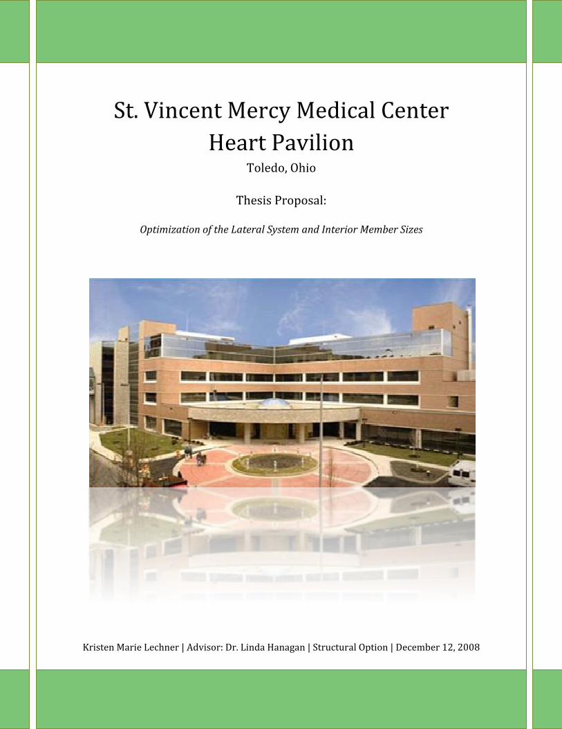
St. Vincent Mercy Medical Center Heart Pavilion
Toledo, Ohio
Thesis Proposal:
Optimization of the Lateral System and Interior Member Sizes
Kristen Marie Lechner | Advisor: Dr. Linda Hanagan | Structural Option | December 12, 2008
Kristen M. Lechner Page 2
TABLE OF CONTENTS
Table of Contents…………………………………………………………………………………………………... 2
Executive Summary……………………………………………………………………………………………….. 3
Introduction: St. Vincent Mercy Medical Center Heart Pavilion………………………………... 4
Existing Structural Description………………………………………………………………………………. 5
Floor System…………………………………………………………………………………………..…. 5
Roof System………………………………………………………………………………………………. 6
Columns…………………………………………………..………………………………………………... 6
Lateral System………………………………………………………………………………………..…. 6
Foundation System…………………………………………………………………………………..... 8
Problem Statement………………………………………………………………………………………………... 9
Proposed Solution…………………………………………………………………………………………………. 10
Structural Depth: New Lateral System………………………………………………………… 10
Breadth Study I: Geotechnical Investigation………………………………………………... 10
Breadth Study II: Construction Management………………………………………………. 11
Tasks & Tools………………………………………………………………………………………………………... 12
Timeline………………………………………………………………………………………………………………... 14
Kristen M. Lechner Page 3
EXECUTIVE SUMMARY
St. Vincent Mercy Medical Center Heart Pavilion is a four story hospital that provides diagnostics, surgery, and patient care. It was constructed for St. Vincent’s Mercy Medical Center Campus, established in 1855, in downtown Toledo, Ohio.
The facility is approximately 144,000 square feet and reaches a height of 57’5” above grade with a typical floor to floor height of approximately 14 feet. A typical interior bay is 30 feet by 35 feet and is comprised of composite steel with a concrete slab on deck. Non‐seismic steel moment frames are utilized to resist lateral forces at every column in both directions. This structural system was evaluated in previous technical reports and it was determined that the system meets architectural, strength, and serviceability requirements. Upon investigation of the soil classification within the site, it was determined that the soil was classified as Site Class E. As a result, it was concluded that the best solution for the Heart Pavilion is a structural steel system as this material is lighter than concrete and will have less impact on foundation selection.
The current site of St. Vincent Mercy Medical Center Heart Pavilion was chosen by the owner because it was already owned by Mercy Health Partners and it is adjacent to the main hospital. For these reasons, the Heart Pavilion will be kept on the existing site.
This thesis proposal outlines steps that will be taken in order to optimize the existing lateral system as well as interior member sizes. Classified as Site Class E, the soil is very sensitive to seismic forces. As a result, it was necessary at the time of design to place non‐seismic steel moment frames at every column in both directions. In order to optimize this lateral system, seismically detailed steel moment frames will be utilized to resist lateral loads. These seismically detailed steel moment frames will be placed along the perimeter of the building to ultimately reduce interior member sizes. Structural computer modeling will be used in order complete this design. In addition to designing the new lateral system, the seismically detailed connections will be designed based on applicable limit states.
A geotechnical investigation will also be provided in order to further verify that the site soils are soft in nature. The use of geopiers will also be researched and designed. By utilizing this foundation system lateral pressure within the soil will be increased, creating vertical reinforcement for the soil.
Implementing special detailing of the lateral system will require special welders to install the connections and special inspectors to regularly visit the construction site. For this reason, a construction schedule will be provided for the existing lateral system as well as the proposed lateral system. Conclusions will then be drawn based on viability of the new lateral system with respect to cost and constructability.
Kristen M. Lechner Page 4
INTRODUCTION: ST. VINCENT MERCY MEDICAL CENTER HEART PAVILION
St. Vincent’s Heart Pavilion is one of the seven hospitals that comprise Mercy Health Partners. As Toledo’s first and only facility for the treatment of vascular disease, St. Vincent’s Heart Pavilion has become a staple within the community. St. Vincent’s Mercy Medical Center Campus is now able to take a leadership role in providing education to its students as well as saving lives through the treatment of vascular disease.
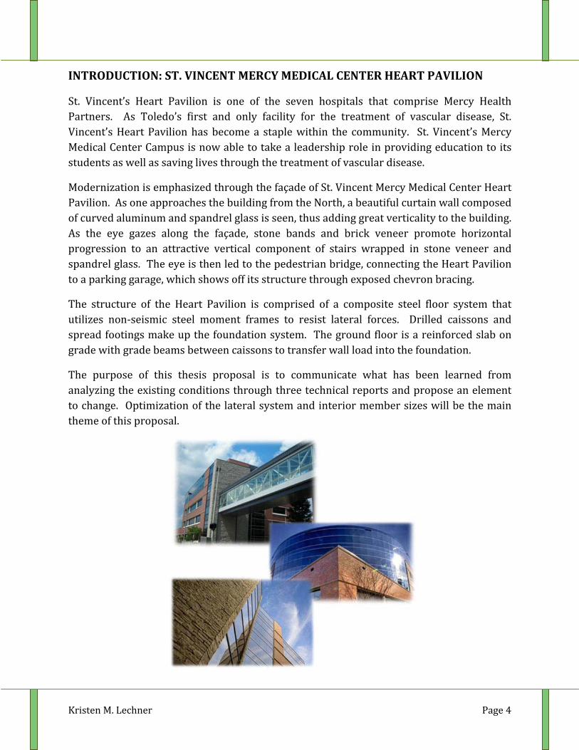
Modernization is emphasized through the façade of St. Vincent Mercy Medical Center Heart Pavilion. As one approaches the building from the North, a beautiful curtain wall composed of curved aluminum and spandrel glass is seen, thus adding great verticality to the building. As the eye gazes along the façade, stone bands and brick veneer promote horizontal progression to an attractive vertical component of stairs wrapped in stone veneer and spandrel glass. The eye is then led to the pedestrian bridge, connecting the Heart Pavilion to a parking garage, which shows off its structure through exposed chevron bracing.
The structure of the Heart Pavilion is comprised of a composite steel floor system that utilizes non‐seismic steel moment frames to resist lateral forces. Drilled caissons and spread footings make up the foundation system. The ground floor is a reinforced slab on grade with grade beams between caissons to transfer wall load into the foundation.
The purpose of this thesis proposal is to communicate what has been learned from analyzing the existing conditions through three technical reports and propose an element to change. Optimization of the lateral system and interior member sizes will be the main theme of this proposal.
Kristen M. Lechner Page 5
EXISTING STRUCTURAL DESCRIPTION
Floor System
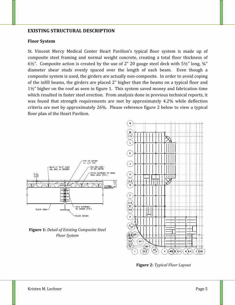
St. Vincent Mercy Medical Center Heart Pavilion’s typical floor system is made up of composite steel framing and normal weight concrete, creating a total floor thickness of 6½”. Composite action is created by the use of 2” 20 gauge steel deck with 5½” long, ¾” diameter shear studs evenly spaced over the length of each beam. Even though a composite system is used, the girders are actually non‐composite. In order to avoid coping of the infill beams, the girders are placed 2” higher than the beams on a typical floor and 1½” higher on the roof as seen in figure 1. This system saved money and fabrication time which resulted in faster steel erection. From analysis done in previous technical reports, it was found that strength requirements are met by approximately 4.2% while deflection criteria are met by approximately 26%. Please reference figure 2 below to view a typical floor plan of the Heart Pavilion.
Figure 1: Detail of Existing Composite Steel Floor System
Figure 2: Typical Floor Layout
Kristen M. Lechner Page 6
Roof System
The roof system is comprised W14x22 beams framing into W18X40 girders. This system was used as opposed to joists because surgery space was originally located directly below the main roof. The mechanical and medical equipment required for these spaces is easier to hang from wide flange beams.
The roof envelope is surrounded by a parapet wall. The roof system is made up of two systems: 1 ½” x 22 GA. galvanized steel roof deck providing enclosure to the building, and 6 ½” normal weight concrete on 1 ½” 20 GA. galvanized metal deck providing support for the mechanical equipment located in the two penthouses. Both systems are topped with a single ply membrane, ¾” plywood, and a minimum of 3” rigid insulation.
Columns
The columns used in St. Vincent Mercy Medical Center Heart Pavilion range from W10x119’s to W12x210’s, depending on their location within the building. While these sizes may seem large based purely on gravity, each column must resist induced moment since all columns are part of a moment frame. Pipe columns are used to support the roof for the main entrance lobby and the emergency vestibule canopy. All of the main building columns are spliced at the 2nd‐3rd floor. Base plates range in thickness from 1” to 2 ¼” depending on which columns they are supporting. Each base plate utilizes a standard 4 bolt connection using either ¾” A325 or 1 ¼” A325 bolts.
Lateral System
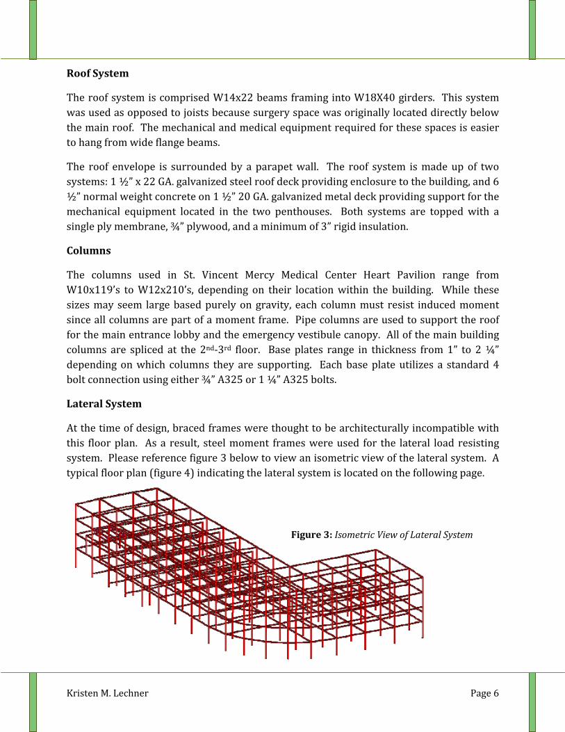
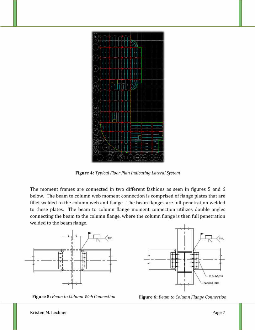
At the time of design, braced frames were thought to be architecturally incompatible with this floor plan. As a result, steel moment frames were used for the lateral load resisting system. Please reference figure 3 below to view an isometric view of the lateral system. A typical floor plan (figure 4) indicating the lateral system is located on the following page.
Figure 3: Isometric View of Lateral System
Kristen M. Lechner Page 7
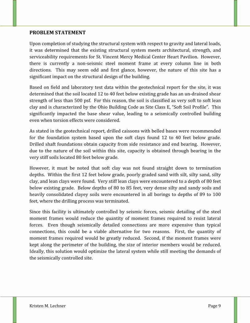
The moment frames are connected in two different fashions as seen in figures 5 and 6 below. The beam to column web moment connection is comprised of flange plates that are fillet welded to the column web and flange. The beam flanges are full‐penetration welded to these plates. The beam to column flange moment connection utilizes double angles connecting the beam to the column flange, where the column flange is then full penetration welded to the beam flange.
Figure 5: Beam to Column Web Connection Figure 6: Beam to Column Flange Connection
Figure 4: Typical Floor Plan Indicating Lateral System

Kristen M. Lechner Page 8
Foundation System
The foundation system is made up of 80 drilled caissons and 6 spread footings that support the entrance lobby. The caisson caps are a uniform size of 4’x4’x3’ thick. Between caissons are grade beams, varying in depth from 2’ to 4’ depending on the location, which transfer façade and wall load to the foundation system. The ground (main) floor rests on a 6” concrete slab reinforced with W/4x4‐W4.0x4.0 welded wire fabric.
The use of a deep foundation system with structural steel framing may seem odd at first glance, however site soils were reported to be very soft in nature. When the geotechnical investigation was done, it was found that within the first 12 feet below grade poorly graded sand with silt, silty sand, silty clay, and lean clays were found. Very stiff lean clays were encountered to a depth of 80 feet below existing grade. Below depths of 80 to 85 feet, very dense silty and sandy soils and heavily consolidated clayey soils were encountered in all borings to depths of 89 to 100 feet, where the drilling process was terminated. As a result, drilled caissons with belled bases were recommended for the foundation system based upon the soft clays found 12 to 40 feet below grade.
Figure 7: Caisson Detail at Interior Grade Beam
Kristen M. Lechner Page 9
PROBLEM STATEMENT
Upon completion of studying the structural system with respect to gravity and lateral loads, it was determined that the existing structural system meets architectural, strength, and serviceability requirements for St. Vincent Mercy Medical Center Heart Pavilion. However, there is currently a non‐seismic steel moment frame at every column line in both directions. This may seem odd and first glance, however, the nature of this site has a significant impact on the structural design of the building.
Based on field and laboratory test data within the geotechnical report for the site, it was determined that the soil located 12 to 40 feet below existing grade has an un‐drained shear strength of less than 500 psf. For this reason, the soil is classified as very soft to soft lean clay and is characterized by the Ohio Building Code as Site Class E, “Soft Soil Profile”. This significantly impacted the base shear value, leading to a seismically controlled building even when torsion effects were considered.
As stated in the geotechnical report, drilled caissons with belled bases were recommended for the foundation system based upon the soft clays found 12 to 40 feet below grade. Drilled shaft foundations obtain capacity from side resistance and end bearing. However, due to the nature of the soil within this site, capacity is obtained through bearing in the very stiff soils located 80 feet below grade.
However, it must be noted that soft clay was not found straight down to termination depths. Within the first 12 feet below grade, poorly graded sand with silt, silty sand, silty clay, and lean clays were found. Very stiff lean clays were encountered to a depth of 80 feet below existing grade. Below depths of 80 to 85 feet, very dense silty and sandy soils and heavily consolidated clayey soils were encountered in all borings to depths of 89 to 100 feet, where the drilling process was terminated.
Since this facility is ultimately controlled by seismic forces, seismic detailing of the steel moment frames would reduce the quantity of moment frames required to resist lateral forces. Even though seismically detailed connections are more expensive than typical connections, this could be a viable alternative for two reasons. First, the quantity of moment frames required would be greatly reduced. Second, if the moment frames were kept along the perimeter of the building, the size of interior members would be reduced. Ideally, this solution would optimize the lateral system while still meeting the demands of the seismically controlled site.
Kristen M. Lechner Page 10
PROPOSED SOLUTION
Theme: Optimizing the Lateral System and Minimizing Interior Member Sizes
Structural Depth: New Lateral System Design
The current site of St. Vincent Mercy Medical Center Heart Pavilion was chosen by the owner because it was already owned by Mercy Health Partners and it is adjacent to the main hospital. As Toledo’s first and only facility for the treatment of vascular disease, St. Vincent’s Heart Pavilion has become a staple within the community. For these reasons, the Heart Pavilion will be kept on the existing site.
Due to the nature of the soil, steel is the best solution for a structural system. Concrete is a heavier material by nature and would only increase the weight of the building, creating an even higher base shear value. As a result, the Heart Pavilion will remain a composite steel structure.
Classified as Site Class E, the soil is very sensitive to seismic forces. As a result, it was necessary at the time of design to place non‐seismic steel moment frames at every column in both directions. In order to optimize this lateral system, seismically detailed steel moment frames will be utilized to resist lateral loads. These seismically detailed steel moment frames will be placed along the perimeter of the building to ultimately reduce interior member sizes.
After designing the new lateral system, the seismically detailed connections will be designed based on applicable limit states. These connections will be detailed in AutoCAD and provided for reference with the new lateral system.
A cost analysis will be prepared for the existing lateral system as well and the new lateral system in order to create a side by side comparison. Ideally, cost savings will be discovered with the new lateral system due to the reduced quantity of moment frames. However, availability of welders and special inspectors in the Toledo area must be considered within this cost analysis.
Breadth Study I: Geotechnical Investigation
The geotechnical contractor will be contacted in order to discuss the soil classification method used and if there are alternative methods that may be used. The use of geopiers will also be discussed in efforts to improve the conditions of the soil.
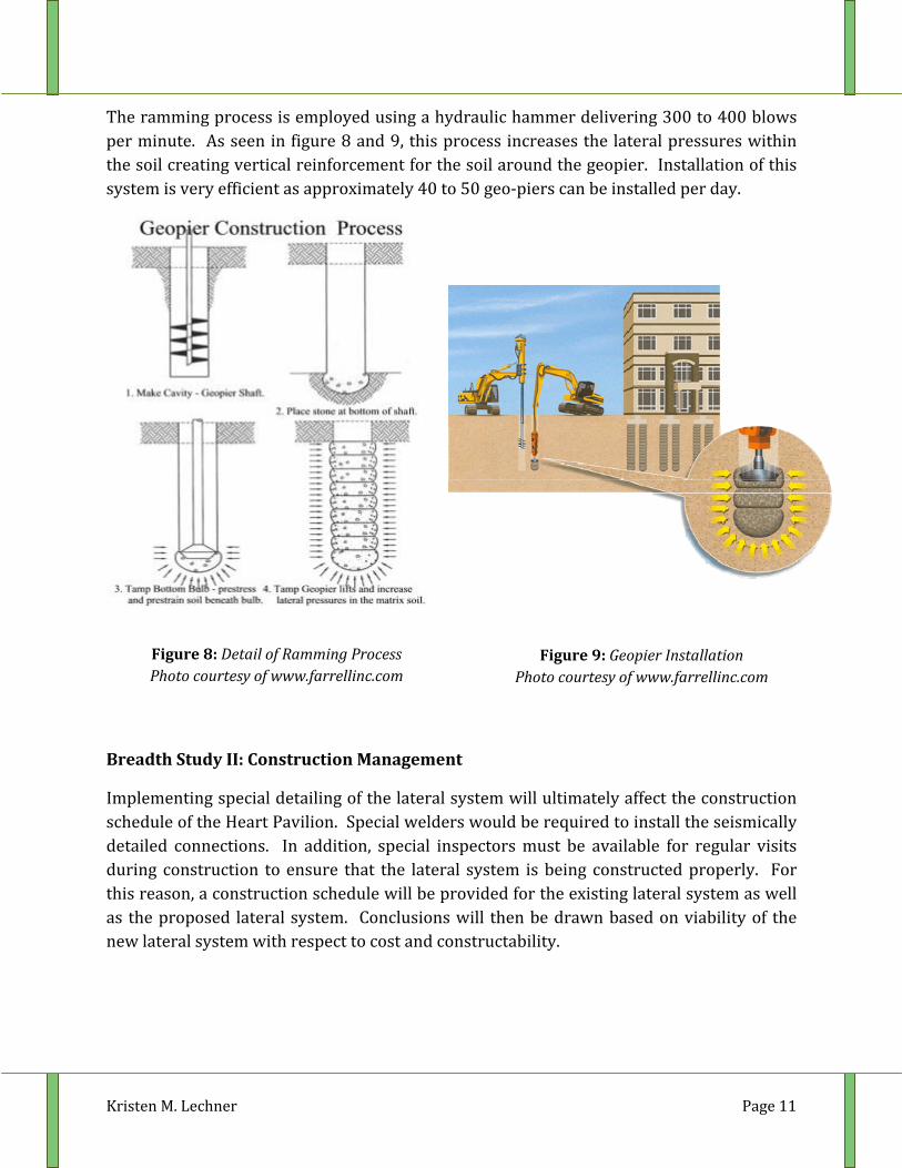
Within soft soil regions, geopiers are a great solution for a foundation system. They are installed by drilling a 30” diameter shaft and then ramming hard aggregate into the shaft in 12” lifts. This aggregate must be high quality and high hardness, or it will be destroyed.
Kristen M. Lechner Page 11
The ramming process is employed using a hydraulic hammer delivering 300 to 400 blows per minute. As seen in figure 8 and 9, this process increases the lateral pressures within the soil creating vertical reinforcement for the soil around the geopier. Installation of this system is very efficient as approximately 40 to 50 geo‐piers can be installed per day.
Breadth Study II: Construction Management
Implementing special detailing of the lateral system will ultimately affect the construction schedule of the Heart Pavilion. Special welders would be required to install the seismically detailed connections. In addition, special inspectors must be available for regular visits during construction to ensure that the lateral system is being constructed properly. For this reason, a construction schedule will be provided for the existing lateral system as well as the proposed lateral system. Conclusions will then be drawn based on viability of the new lateral system with respect to cost and constructability.
Figure 8: Detail of Ramming Process Photo courtesy of www.farrellinc.com
Figure 9: Geopier Installation Photo courtesy of www.farrellinc.com
Kristen M. Lechner Page 12
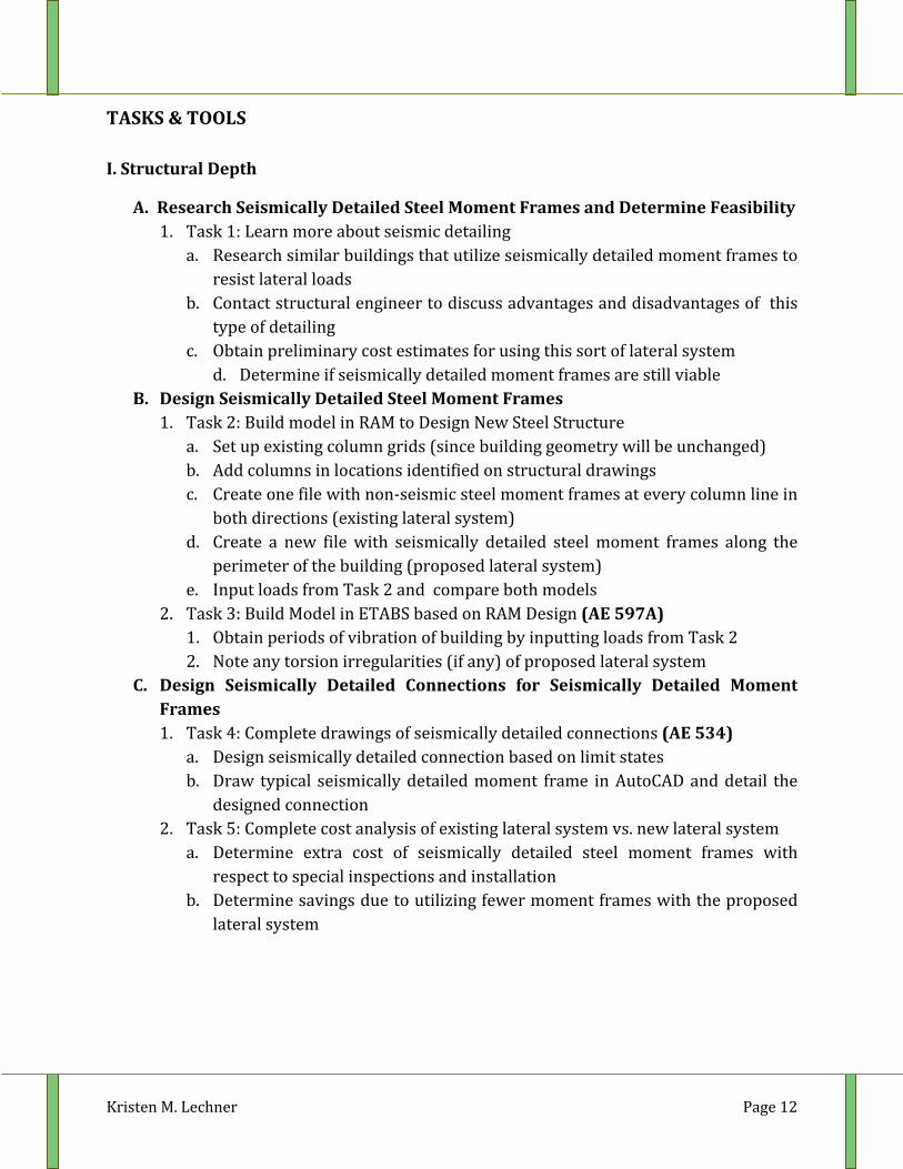
TASKS & TOOLS I. Structural Depth
A. Research Seismically Detailed Steel Moment Frames and Determine Feasibility 1. Task 1: Learn more about seismic detailing
a. Research similar buildings that utilize seismically detailed moment frames to resist lateral loads
b. Contact structural engineer to discuss advantages and disadvantages of this type of detailing
c. Obtain preliminary cost estimates for using this sort of lateral system d. Determine if seismically detailed moment frames are still viable
B. Design Seismically Detailed Steel Moment Frames 1. Task 2: Build model in RAM to Design New Steel Structure
a. Set up existing column grids (since building geometry will be unchanged) b. Add columns in locations identified on structural drawings c. Create one file with non‐seismic steel moment frames at every column line in
both directions (existing lateral system) d. Create a new file with seismically detailed steel moment frames along the
perimeter of the building (proposed lateral system) e. Input loads from Task 2 and compare both models
2. Task 3: Build Model in ETABS based on RAM Design (AE 597A) 1. Obtain periods of vibration of building by inputting loads from Task 2 2. Note any torsion irregularities (if any) of proposed lateral system
C. Design Seismically Detailed Connections for Seismically Detailed Moment Frames 1. Task 4: Complete drawings of seismically detailed connections (AE 534)
a. Design seismically detailed connection based on limit states b. Draw typical seismically detailed moment frame in AutoCAD and detail the
designed connection 2. Task 5: Complete cost analysis of existing lateral system vs. new lateral system
a. Determine extra cost of seismically detailed steel moment frames with respect to special inspections and installation
b. Determine savings due to utilizing fewer moment frames with the proposed lateral system
Kristen M. Lechner Page 13
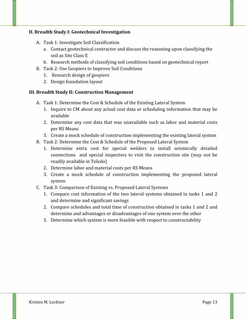
II. Breadth Study I: Geotechnical Investigation
A. Task 1: Investigate Soil Classification a. Contact geotechnical contractor and discuss the reasoning upon classifying the
soil as Site Class E b. Research methods of classifying soil conditions based on geotechnical report
B. Task 2: Use Geopiers to Improve Soil Conditions 1. Research design of geopiers 2. Design foundation layout
III. Breadth Study II: Construction Management
A. Task 1: Determine the Cost & Schedule of the Existing Lateral System 1. Inquire to CM about any actual cost data or scheduling information that may be
available 2. Determine any cost data that was unavailable such as labor and material costs
per RS Means 3. Create a mock schedule of construction implementing the existing lateral system
B. Task 2: Determine the Cost & Schedule of the Proposed Lateral System 1. Determine extra cost for special welders to install seismically detailed
connections and special inspectors to visit the construction site (may not be readily available in Toledo)
2. Determine labor and material costs per RS Means 3. Create a mock schedule of construction implementing the proposed lateral
system C. Task 3: Comparison of Existing vs. Proposed Lateral Systems
1. Compare cost information of the two lateral systems obtained in tasks 1 and 2 and determine and significant savings
2. Compare schedules and total time of construction obtained in tasks 1 and 2 and determine and advantages or disadvantages of one system over the other
3. Determine which system is more feasible with respect to constructability
Kristen M. Lechner Page 14
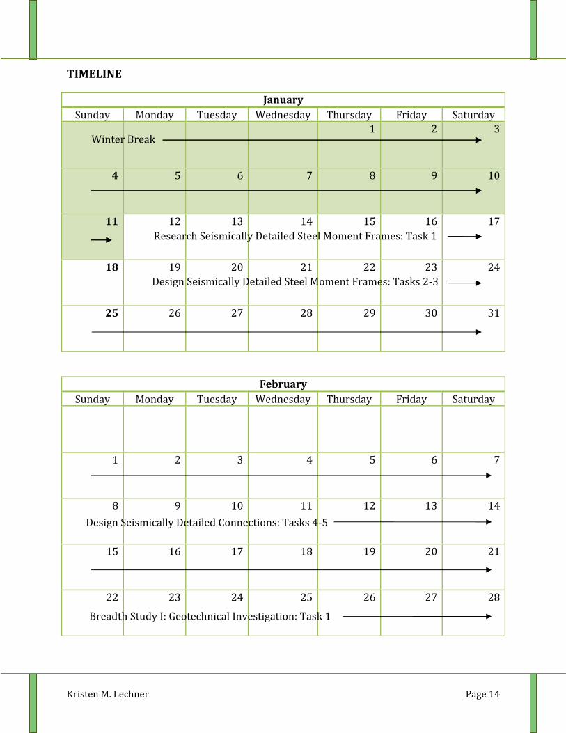
TIMELINE
January Sunday Monday Tuesday Wednesday Thursday Friday Saturday
1 2 3
4 5 6 7 8 9 10
11 12 13 14 15 16 17
18 19 20 21 22 23 24
25 26 27 28 29 30 31
February Sunday Monday Tuesday Wednesday Thursday Friday Saturday
1 2 3 4 5 6 7
8 9 10 11 12 13 14
15 16 17 18 19 20 21
22 23 24 25 26 27 28
Winter Break
Research Seismically Detailed Steel Moment Frames: Task 1
Design Seismically Detailed Steel Moment Frames: Tasks 2‐3
Design Seismically Detailed Connections: Tasks 4‐5
Breadth Study I: Geotechnical Investigation: Task 1
Kristen M. Lechner Page 15
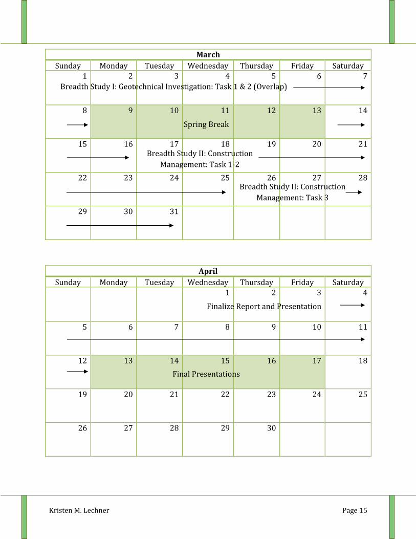
March Sunday Monday Tuesday Wednesday Thursday Friday Saturday
1 2 3 4 5 6 7
8 9 10 11 12 13 14
15 16 17 18 19 20 21
22 23 24 25 26 27 28
29 30 31
April Sunday Monday Tuesday Wednesday Thursday Friday Saturday
1 2 3 4
5 6 7 8 9 10 11
12 13 14 15 16 17 18
19 20 21 22 23 24 25
26 27 28 29 30
Final Presentations
Spring Break
Finalize Report and Presentation
Breadth Study II: Construction Management: Task 1‐2
Breadth Study II: Construction Management: Task 3
Breadth Study I: Geotechnical Investigation: Task 1 & 2 (Overlap)