Embed Size (px)
Citation preview
ST1332Snow Thrower
MTF−051059L
OPERATOR’SMANUAL
INTRODUCTION
2MTF−051059L
Congratulations on your purchase of a Frontier Snowthrower. It has been designed, engineered and manufactured to give youthe best possible dependability and performance. However, like all mechanical products, your machine will occasionally re-quire adjustment and maintenance. This handbook should be read before operating or performing and adjustments on yourmachine.
The instructions in this Owner’s Manual are written for a person with some mechanical ability. Like most service books, notall the steps are described. Steps on how to loosen or tighten fasteners are steps anyone can follow with some mechanicalability. Read and follow these instructions before you use the unit.
Know your product:: If you understand the unit and how the unit operates, you will get the best performance. As you readthis manual, compare the illustrations to the unit. Learn the location and the function of the controls. To help prevent an acci-dent, follow the operating instructions and the safety rules. Keep this manual for future reference.
IMPORTANT: Many units are not assembled and are sold in cartons. It is the responsibility of the owner to make sure the as-sembly instructions in this manual are exactly followed. Other units are purchased in an assembled condition. On assembledunits, it is the responsibility of the owner to make sure the unit is correctly assembled. The owner must carefully check the unitaccording to the instructions in this manual before it is first used.
The warranty, found in this manual, details the coverage and limitations of this product. Registration of the warranty isnecessary and must be preformed by the dealer within sixty (60) days from the date of retail sale or delivery. TheWarranty Registration Form is located on the Frontier website.
RESPONSIBILITY OF THE OWNERThe responsibility of the owners to follow the instructions below.
1. Carefully read and follow the rules for safe operation.
2. Follow all the assembly instructions.
3. Inspect the unit.
4. Make sure that the operator of the unit knows how to correctly use all standard and accessory equipment.
5. Operate the unit only with guards, shields, and other safety items in place and working correctly.
6. Correctly adjust the unit.
7. Service the unit only with authorized or approved replacement parts.
8. Complete all maintenance on the unit.
Read And Keep This Book For Future Reference. This Book Contains Important Information On:
SAFETY, ASSEMBLY, OPERATION AND MAINTENANCE.
PRODUCT INFORMATIONThe owner must be certain that all the product information is included with this unit.
This information includes the INSTRUCTION BOOKS, the REPLACEMENT PARTSand the WARRANTIES. This information must be included to make
sure state laws and other laws are followed.
RULES FOR SAFE OPERATION
3MTF−051059L
This manual contains safety information to make youaware of the hazards and risks associated with snow
throwers, and how to avoid them. The snow thrower is designed andintended for removal of snow, and should not be used for any otherpurpose. It is important that you read and understand theseinstructions, and anyone operating the equipment read andunderstand these instructions.
The engine exhaust from this product contains chemicals known to theState of California to cause cancer, birth defects, or other reproductiveharm.
WARNING
A signal word (DANGER, WARNING, or CAUTION) is used with the alertsymbol to indicate the likelihood and the potential severity of injury. Inaddition, a hazard symbol may be used to represent the type of hazard.
DANGER indicates a hazard which, if not avoided, will result indeath or serious injury.
WARNING indicates a hazard which, if not avoided, could resultin death or serious injury.
CAUTION indicates a hazard which, if not avoided, might resultin minor or moderate injury.CAUTION, when used without the alert symbol, indicates asituation that could result in damage to the equipment.
Hazard Symbols and the meanings
These symbols are used on your equipment and defined in your operating
manual. Review and understand the meanings. The use of one of these
symbols combined with a signal word will alert you to potential hazards
and how to avoid them.
Explosion
Toxic fumes Shock
Hot Surface
Fire
Operator’s Manual − Read and understandbefore performing any activity or runningequipment.
Safety Alert − Identifies safety information abouthazards that can result in personal injury.
Rotating auger
Rotating impeller
Rotating gears
Thrown objects
Keep a safe distancefrom the equipment.
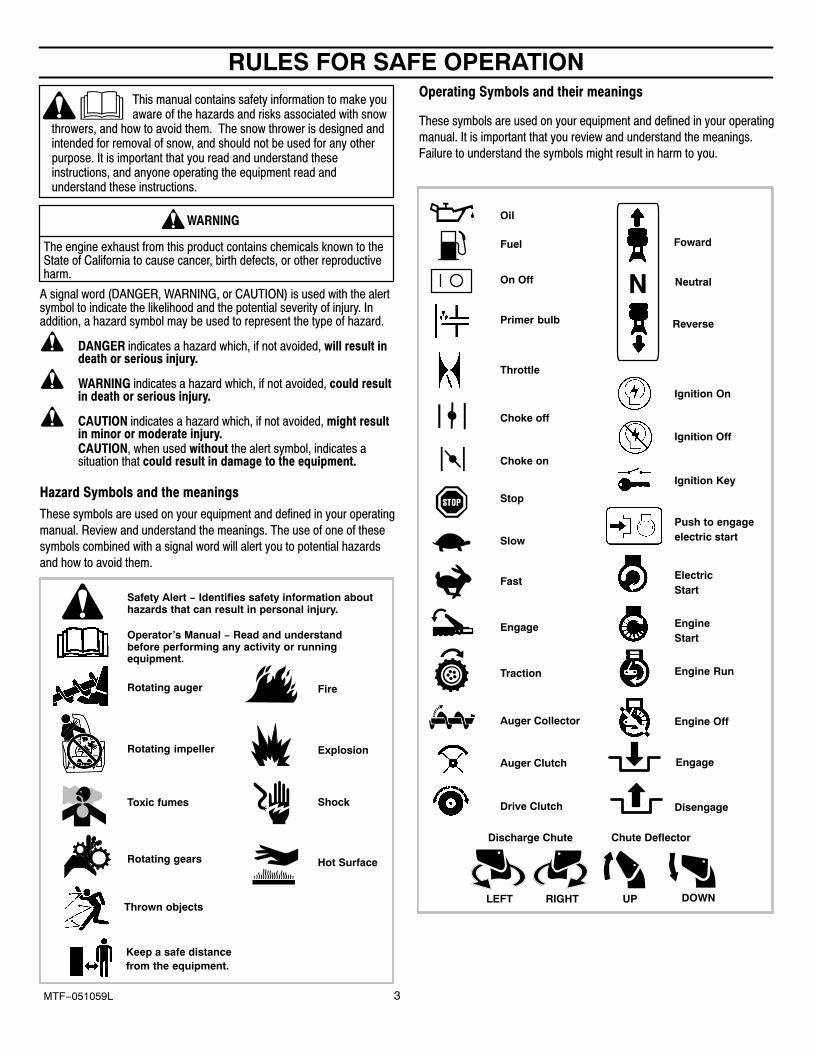
Operating Symbols and their meanings
These symbols are used on your equipment and defined in your operating
manual. It is important that you review and understand the meanings.
Failure to understand the symbols might result in harm to you.
Stop
Fuel
Choke off
Oil
Choke on
Slow
Fast
On Off
Ignition Key
Ignition Off
Ignition On
Primer bulb
Throttle
Drive Clutch
Auger Clutch
Engage
RIGHT
Auger Collector
Traction
Discharge Chute
LEFT UP DOWN
Foward
Neutral
Reverse
Push to engageelectric start
ElectricStart
EngineStart
Engine Run
Engine Off
Chute Deflector
Engage
Disengage
RULES FOR SAFE OPERATION
4MTF−051059L
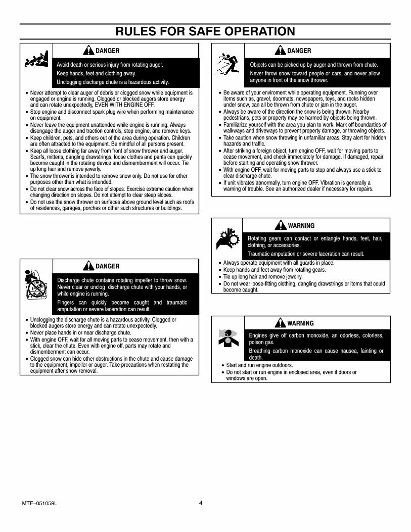
Avoid death or serious injury from rotating auger.
Keep hands, feet and clothing away.
Unclogging discharge chute is a hazardous activity.
• Never attempt to clear auger of debris or clogged snow while equipment isengaged or engine is running. Clogged or blocked augers store energyand can rotate unexpectedly, EVEN WITH ENGINE OFF.
• Stop engine and disconnect spark plug wire when performing maintenanceon equipment.
• Never leave the equipment unattended while engine is running. Alwaysdisengage the auger and traction controls, stop engine, and remove keys.
• Keep children, pets, and others out of the area during operation. Childrenare often attracted to the equipment. Be mindful of all persons present.
• Keep all loose clothing far away from front of snow thrower and auger.Scarfs, mittens, dangling drawstrings, loose clothes and pants can quicklybecome caught in the rotating device and dismemberment will occur. Tieup long hair and remove jewerly.
• The snow thrower is intended to remove snow only. Do not use for otherpurposes other than what is intended.
• Do not clear snow across the face of slopes. Exercise extreme caution whenchanging direction on slopes. Do not attempt to clear steep slopes.
• Do not use the snow thrower on surfaces above ground level such as roofsof residences, garages, porches or other such structures or buildings.
DANGER
Discharge chute contains rotating impeller to throw snow.Never clear or unclog discharge chute with your hands, orwhile engine is running.
Fingers can quickly become caught and traumaticamputation or severe laceration can result.
• Unclogging the discharge chute is a hazardous activity. Clogged orblocked augers store energy and can rotate unexpectedly.
• Never place hands in or near discharge chute.• With engine OFF, wait for all moving parts to cease movement, then with a
stick, clear the chute. Even with engine off, parts may rotate anddismemberment can occur.
• Clogged snow can hide other obstructions in the chute and cause damageto the equipment, impeller or auger. Take precautions when restating theequipment after snow removal.
DANGER
Objects can be picked up by auger and thrown from chute.
Never throw snow toward people or cars, and never allowanyone in front of the snow thrower.
• Be aware of your enviroment while operating equipment. Running overitems such as, gravel, doormats, newspapers, toys, and rocks hiddenunder snow, can all be thrown from chute or jam in the auger.
• Always be aware of the direction the snow is being thrown. Nearbypedestrians, pets or property may be harmed by objects being thrown.
• Familiarize yourself with the area you plan to work. Mark off boundarties ofwalkways and driveways to prevent property damage, or throwing objects.
• Take caution when snow throwing in unfamiliar areas. Stay alert for hiddenhazards and traffic.
• After striking a foreign object, turn engine OFF, wait for moving parts tocease movement, and check immediately for damage. If damaged, repairbefore starting and operating snow thrower.
• With engine OFF, wait for moving parts to stop and always use a stick toclear discharge chute.
• If unit vibrates abnormally, turn engine OFF. Vibration is generally awarning of trouble. See an authorized dealer if necessary for repairs.
DANGER
Rotating gears can contact or entangle hands, feet, hair,clothing, or accessories.
Traumatic amputation or severe laceration can result.
• Always operate equipment with all guards in place.• Keep hands and feet away from rotating gears.• Tie up long hair and remove jewelry.• Do not wear loose-fitting clothing, dangling drawstrings or items that could
become caught.
WARNING
Engines give off carbon monoxide, an odorless, colorless,poison gas.
Breathing carbon monoxide can cause nausea, fainting ordeath.
• Start and run engine outdoors.• Do not start or run engine in enclosed area, even if doors or
windows are open.
WARNING
RULES FOR SAFE OPERATION
5MTF−051059L
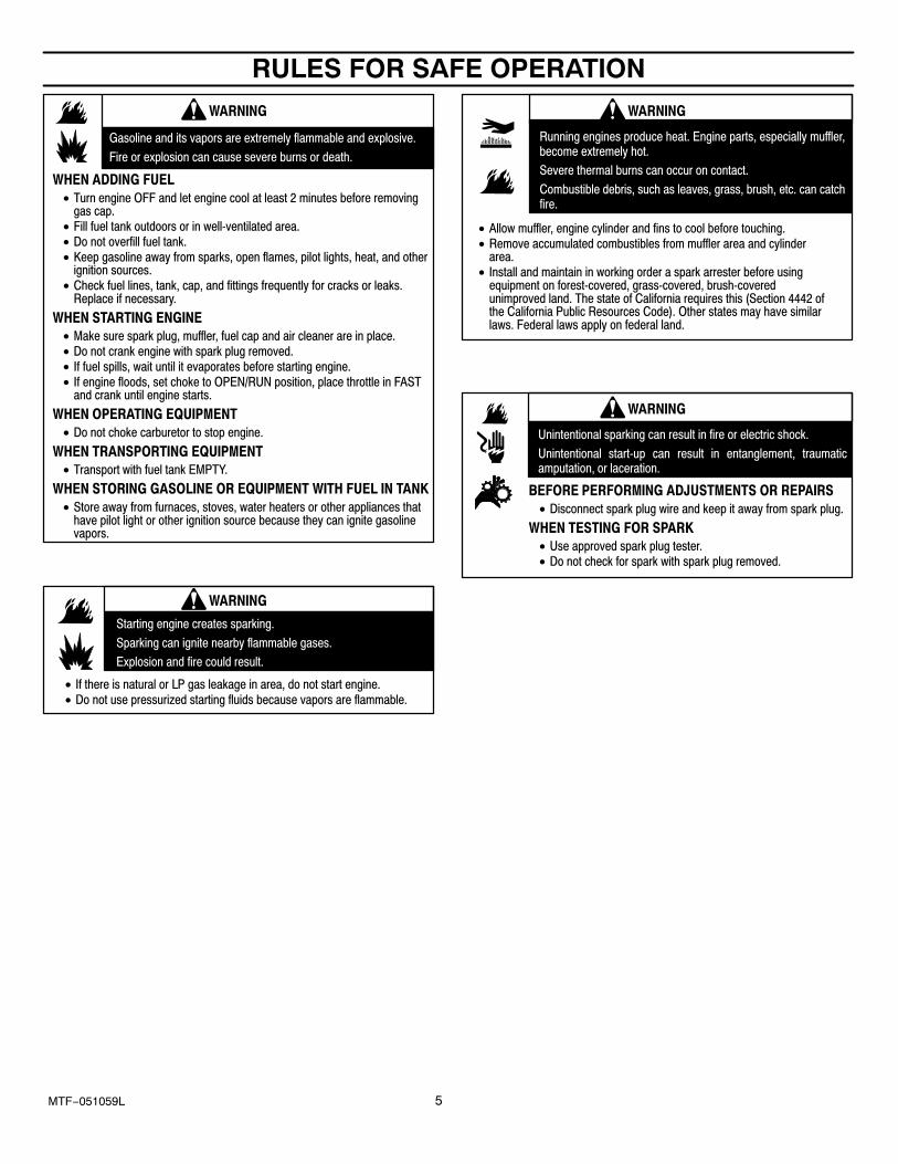
Gasoline and its vapors are extremely flammable and explosive.
Fire or explosion can cause severe burns or death.
WHEN ADDING FUEL
• Turn engine OFF and let engine cool at least 2 minutes before removinggas cap.
• Fill fuel tank outdoors or in well-ventilated area.• Do not overfill fuel tank.• Keep gasoline away from sparks, open flames, pilot lights, heat, and other
ignition sources.• Check fuel lines, tank, cap, and fittings frequently for cracks or leaks.
Replace if necessary.
WHEN STARTING ENGINE
• Make sure spark plug, muffler, fuel cap and air cleaner are in place.• Do not crank engine with spark plug removed.• If fuel spills, wait until it evaporates before starting engine.• If engine floods, set choke to OPEN/RUN position, place throttle in FAST
and crank until engine starts.
WHEN OPERATING EQUIPMENT
• Do not choke carburetor to stop engine.
WHEN TRANSPORTING EQUIPMENT
• Transport with fuel tank EMPTY.
WHEN STORING GASOLINE OR EQUIPMENT WITH FUEL IN TANK
• Store away from furnaces, stoves, water heaters or other appliances thathave pilot light or other ignition source because they can ignite gasolinevapors.
WARNING
Starting engine creates sparking.
Sparking can ignite nearby flammable gases.
Explosion and fire could result.
• If there is natural or LP gas leakage in area, do not start engine.• Do not use pressurized starting fluids because vapors are flammable.
WARNING
• Allow muffler, engine cylinder and fins to cool before touching.• Remove accumulated combustibles from muffler area and cylinder
area.• Install and maintain in working order a spark arrester before using
equipment on forest-covered, grass-covered, brush-coveredunimproved land. The state of California requires this (Section 4442 ofthe California Public Resources Code). Other states may have similarlaws. Federal laws apply on federal land.
WARNING
Running engines produce heat. Engine parts, especially muffler,become extremely hot.
Severe thermal burns can occur on contact.
Combustible debris, such as leaves, grass, brush, etc. can catchfire.
Unintentional sparking can result in fire or electric shock.
Unintentional start-up can result in entanglement, traumaticamputation, or laceration.
BEFORE PERFORMING ADJUSTMENTS OR REPAIRS
• Disconnect spark plug wire and keep it away from spark plug.
WHEN TESTING FOR SPARK
• Use approved spark plug tester.• Do not check for spark with spark plug removed.
WARNING
RULES FOR SAFE OPERATION
6MTF−051059L
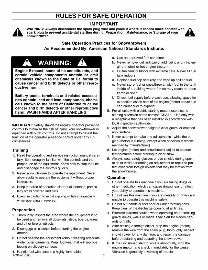
IMPORTANTWARNING: Always disconnect the spark plug wire and place it where it cannot make contact withspark plug to prevent accidental starting during: Preparation, Maintenance, or Storage of yoursnowthrower.
Safe Operation Practices for SnowthrowersAs Recommended By: American National Standards Institute.
Engine Exhaust, some of its constituents, andcertain vehicle components contain or emitchemicals known to the State of California tocause cancer and birth defects or other repro-ductive harm.
Battery posts, terminals and related accesso-ries contain lead and lead compounds, chemi-cals known to the State of California to causecancer and birth defects or other reproductiveharm. WASH HANDS AFTER HANDLING.
IMPORTANT: Safety standards require operator presencecontrols to minimize the risk of injury. Your snowthrower isequipped with such controls. Do not attempt to defeat thefunction of the operator presence control under any cir-cumstances.
Training1. Read the operating and service instruction manual care-
fully. Be thoroughly familiar with the controls and theproper use of the equipment. Know how to stop the unitand disengage the controls quickly.
2. Never allow children to operate the equipment. Neverallow adults to operate the equipment without properinstruction.
3. Keep the area of operation clear of all persons, particu-larly small children and pets.
4. Exercise caution to avoid slipping or falling especiallywhen operating in reverse.
Preparation1. Thoroughly inspect the area where the equipment is to
be used and remove all doormats, sleds, boards, wires,and other foreign objects.
2. Disengage all clutches before starting the engine(motor).
3. Do not operate the equipment without wearing adequatewinter outer garments. Wear footwear that will improvefooting on slippery surfaces.
4. Handle fuel with care; it is highly flammable.
a. Use an approved fuel container.b. Never remove fuel tank cap or add fuel to a running en-
gine (motor) or hot engine (motor).c. Fill fuel tank outdoors with extreme care. Never fill fuel
tank indoors.d. Replace fuel cap securely and wipe up spilled fuel.e. Never store fuel or snowthrower with fuel in the tank
inside of a building where fumes may reach an openflame or spark.
f. Check fuel supply before each use, allowing space forexpansion as the heat of the engine (motor) and/or suncan cause fuel to expand.
5. For all units with electric starting motors use electricstarting extension cords certified CSA/UL. Use only witha receptacle that has been installed in accordance withlocal inspection authorities.
6. Adjust the snowthrower height to clear gravel or crushedrock surface.
7. Never attempt to make any adjustments while the en-gine (motor) is running (except when specifically recom-mended by manufacturer).
8. Let engine (motor) and snowthrower adjust to outdoortemperatures before starting to clear snow.
9. Always wear safety glasses or eye shields during oper-ation or while performing an adjustment or repair to pro-tect eyes from foreign objects that may be thrown fromthe snowthrower.
Operation1. Do not operate this machine if you are taking drugs or
other medication which can cause drowsiness or affectyour ability to operate this machine.
2. Do not use this machine if you are mentally or physicallyunable to operate this machine safely.
3. Do not put hands or feet near or under rotating parts.Keep clear of the discharge opening at all times.
4. Exercise extreme caution when operating on or crossinggravel drives, walks or roads. Stay alert for hidden haz-ards or traffic.
5. After striking a foreign object, stop the engine (motor),remove the wire from the spark plug, thoroughly inspectsnowthrower for any damage, and repair the damagebefore restarting and operating the snowthrower.
6. If the unit should start to vibrate abnormally, stop theengine (motor) and check immediately for the cause.Vibration is generally a warning of trouble.
RULES FOR SAFE OPERATION
7MTF−051059L
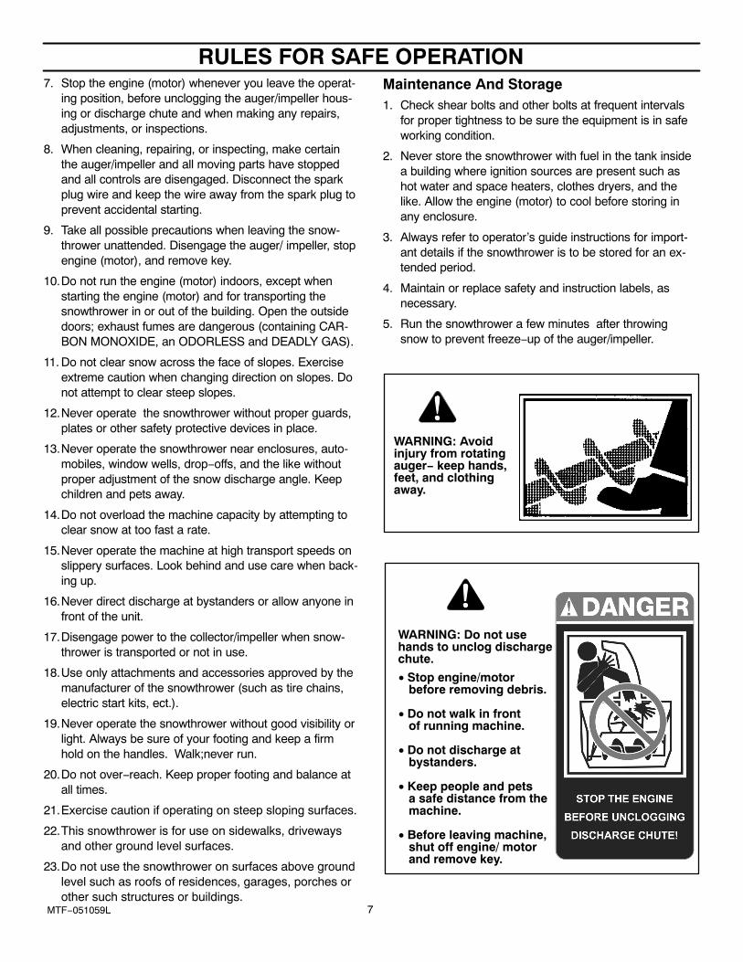
7. Stop the engine (motor) whenever you leave the operat-ing position, before unclogging the auger/impeller hous-ing or discharge chute and when making any repairs,adjustments, or inspections.
8. When cleaning, repairing, or inspecting, make certainthe auger/impeller and all moving parts have stoppedand all controls are disengaged. Disconnect the sparkplug wire and keep the wire away from the spark plug toprevent accidental starting.
9. Take all possible precautions when leaving the snow-thrower unattended. Disengage the auger/ impeller, stopengine (motor), and remove key.
10.Do not run the engine (motor) indoors, except whenstarting the engine (motor) and for transporting thesnowthrower in or out of the building. Open the outsidedoors; exhaust fumes are dangerous (containing CAR-BON MONOXIDE, an ODORLESS and DEADLY GAS).
11. Do not clear snow across the face of slopes. Exerciseextreme caution when changing direction on slopes. Donot attempt to clear steep slopes.
12.Never operate the snowthrower without proper guards,plates or other safety protective devices in place.
13.Never operate the snowthrower near enclosures, auto-mobiles, window wells, drop−offs, and the like withoutproper adjustment of the snow discharge angle. Keepchildren and pets away.
14.Do not overload the machine capacity by attempting toclear snow at too fast a rate.
15.Never operate the machine at high transport speeds onslippery surfaces. Look behind and use care when back-ing up.
16.Never direct discharge at bystanders or allow anyone infront of the unit.
17.Disengage power to the collector/impeller when snow-thrower is transported or not in use.
18.Use only attachments and accessories approved by themanufacturer of the snowthrower (such as tire chains,electric start kits, ect.).
19.Never operate the snowthrower without good visibility orlight. Always be sure of your footing and keep a firmhold on the handles. Walk;never run.
20.Do not over−reach. Keep proper footing and balance atall times.
21.Exercise caution if operating on steep sloping surfaces.
22.This snowthrower is for use on sidewalks, drivewaysand other ground level surfaces.
23.Do not use the snowthrower on surfaces above groundlevel such as roofs of residences, garages, porches orother such structures or buildings.
Maintenance And Storage1. Check shear bolts and other bolts at frequent intervals
for proper tightness to be sure the equipment is in safeworking condition.
2. Never store the snowthrower with fuel in the tank insidea building where ignition sources are present such ashot water and space heaters, clothes dryers, and thelike. Allow the engine (motor) to cool before storing inany enclosure.
3. Always refer to operator’s guide instructions for import-ant details if the snowthrower is to be stored for an ex-tended period.
4. Maintain or replace safety and instruction labels, asnecessary.
5. Run the snowthrower a few minutes after throwingsnow to prevent freeze−up of the auger/impeller.
WARNING: Avoidinjury from rotatingauger− keep hands,feet, and clothingaway.
• Stop engine/motor before removing debris.
• Do not walk in front of running machine.
• Do not discharge at bystanders.
• Keep people and pets a safe distance from the machine.
• Before leaving machine, shut off engine/ motor and remove key.
WARNING: Do not usehands to unclog dischargechute.
TABLE OF CONTENTS
8MTF−051059L
HAZARD SYMBOLS AND THE MEANINGS 3. . . . . . . . . . . . . . . . . . . . . . . OPERATING SYMBOLS AND THEIR MEANINGS 3. . . . . . . . . . . . . . . . . . SAFETY DECALS 9. . . . . . . . . . . . . . . . . . . . . . . . . . . . . . . . . . . . . . . . . . . . . . WARRANTY 10. . . . . . . . . . . . . . . . . . . . . . . . . . . . . . . . . . . . . . . . . . . . . . . . . . . OWNER’S INFORMATION 10. . . . . . . . . . . . . . . . . . . . . . . . . . . . . . . . . . . . . . . ASSEMBLY 11. . . . . . . . . . . . . . . . . . . . . . . . . . . . . . . . . . . . . . . . . . . . . . . . . . . .
TOOLS REQUIRED FOR ASSEMBLY 11. . . . . . . . . . . . . . . . . . . . . . . . . . . . . . . . . CONTENTS OF SHIPPING CARTON 11. . . . . . . . . . . . . . . . . . . . . . . . . . . . . . . . . . PARTS BAGS CONTENTS 11. . . . . . . . . . . . . . . . . . . . . . . . . . . . . . . . . . . . . . . . . . . UNPACKING 12. . . . . . . . . . . . . . . . . . . . . . . . . . . . . . . . . . . . . . . . . . . . . . . . . . . . . . . UPPER HANDLE ASSEMBLY 13. . . . . . . . . . . . . . . . . . . . . . . . . . . . . . . . . . . . . . . . CHECK THE CABLES 13. . . . . . . . . . . . . . . . . . . . . . . . . . . . . . . . . . . . . . . . . . . . . . . HOW TO SET THE LENGTH OF THE CABLES 13. . . . . . . . . . . . . . . . . . . . . . . . . REMOTE CHUTE CONTROL KNOB 14. . . . . . . . . . . . . . . . . . . . . . . . . . . . . . . . . . . SPEED SELECT KNOB 14. . . . . . . . . . . . . . . . . . . . . . . . . . . . . . . . . . . . . . . . . . . . . . HOW TO INSTALL THE SPEED CONTROL ROD 14. . . . . . . . . . . . . . . . . . . . . . . SNOW CHUTE ASSEMBLY 15. . . . . . . . . . . . . . . . . . . . . . . . . . . . . . . . . . . . . . . . . .
OPERATION 16. . . . . . . . . . . . . . . . . . . . . . . . . . . . . . . . . . . . . . . . . . . . . . . . . . . ENGINE AND SNOWTHROWER OPERATING CONTROLS 16. . . . . . . . . . . . . . SNOWTHROWER OPERATION 17. . . . . . . . . . . . . . . . . . . . . . . . . . . . . . . . . . . . . . HOW TO USE THE WHEEL LOCKOUT 18. . . . . . . . . . . . . . . . . . . . . . . . . . . . . . . . HOW TO SET THE DRIFT CUTTERS 18. . . . . . . . . . . . . . . . . . . . . . . . . . . . . . . . . . HOW TO USE THE HEATED GRIPS 18. . . . . . . . . . . . . . . . . . . . . . . . . . . . . . . . . . . BEFORE STARTING ENGINE 19. . . . . . . . . . . . . . . . . . . . . . . . . . . . . . . . . . . . . . . . CHECK THE OIL 19. . . . . . . . . . . . . . . . . . . . . . . . . . . . . . . . . . . . . . . . . . . . . . . . . . . . FILL GAS 19. . . . . . . . . . . . . . . . . . . . . . . . . . . . . . . . . . . . . . . . . . . . . . . . . . . . . . . . . . TO STOP ENGINE 20. . . . . . . . . . . . . . . . . . . . . . . . . . . . . . . . . . . . . . . . . . . . . . . . . . TO START ENGINE 20. . . . . . . . . . . . . . . . . . . . . . . . . . . . . . . . . . . . . . . . . . . . . . . . . HOW TO CLEAR A CLOGGED DISCHARGE CHUTE 22. . . . . . . . . . . . . . . . . . . . HOW TO USE THE CLEAN-OUT TOOL 22. . . . . . . . . . . . . . . . . . . . . . . . . . . . . . . . OPERATING TIPS 23. . . . . . . . . . . . . . . . . . . . . . . . . . . . . . . . . . . . . . . . . . . . . . . . . .
SERVICE RECOMMENDATIONS 24. . . . . . . . . . . . . . . . . . . . . . . . . . . . . . . . . MAINTENANCE 25. . . . . . . . . . . . . . . . . . . . . . . . . . . . . . . . . . . . . . . . . . . . . . . .
SNOWTHROWER 25. . . . . . . . . . . . . . . . . . . . . . . . . . . . . . . . . . . . . . . . . . . . . . . . . . AS REQUIRED 25. . . . . . . . . . . . . . . . . . . . . . . . . . . . . . . . . . . . . . . . . . . . . . . . . . . . . LUBRICATION 25. . . . . . . . . . . . . . . . . . . . . . . . . . . . . . . . . . . . . . . . . . . . . . . . . . . . . . AUGER HOUSING HEIGHT ADJUSTMENT 27. . . . . . . . . . . . . . . . . . . . . . . . . . . . HOW TO REMOVE THE SNOW HOOD 28. . . . . . . . . . . . . . . . . . . . . . . . . . . . . . . . TRACTION DRIVE BELT 29. . . . . . . . . . . . . . . . . . . . . . . . . . . . . . . . . . . . . . . . . . . . . AUGER DRIVE BELT 30. . . . . . . . . . . . . . . . . . . . . . . . . . . . . . . . . . . . . . . . . . . . . . . . HOW TO REMOVE THE AUGER DRIVE BELT 31. . . . . . . . . . . . . . . . . . . . . . . . . . HOW TO REMOVE THE TRACTION DRIVE BELT 32. . . . . . . . . . . . . . . . . . . . . . . AUGER BELT GUIDE ADJUSTMENT 33. . . . . . . . . . . . . . . . . . . . . . . . . . . . . . . . . . TRACTION DRIVE BELT GUIDE ADJUSTMENT 33. . . . . . . . . . . . . . . . . . . . . . . . HOW TO CHECK AND ADJUST THE CABLES 34. . . . . . . . . . . . . . . . . . . . . . . . . AUGER DRIVE CABLE ADJUSTMENT 34. . . . . . . . . . . . . . . . . . . . . . . . . . . . . . . . AUGER SHEAR BOLT REPLACEMENT 35. . . . . . . . . . . . . . . . . . . . . . . . . . . . . . . . SPARK PLUG 35. . . . . . . . . . . . . . . . . . . . . . . . . . . . . . . . . . . . . . . . . . . . . . . . . . . . . .
STORAGE 36. . . . . . . . . . . . . . . . . . . . . . . . . . . . . . . . . . . . . . . . . . . . . . . . . . . . . TROUBLE SHOOTING CHART 37. . . . . . . . . . . . . . . . . . . . . . . . . . . . . . . . . . REPLACEMENT PARTS 40. . . . . . . . . . . . . . . . . . . . . . . . . . . . . . . . . . . . . . . . . PARTS SCHEMATICS 41. . . . . . . . . . . . . . . . . . . . . . . . . . . . . . . . . . . . . . . . . . . SPECIFICATIONS 60. . . . . . . . . . . . . . . . . . . . . . . . . . . . . . . . . . . . . . . . . . . . . .
SAFETY DECALS
9MTF−051059L
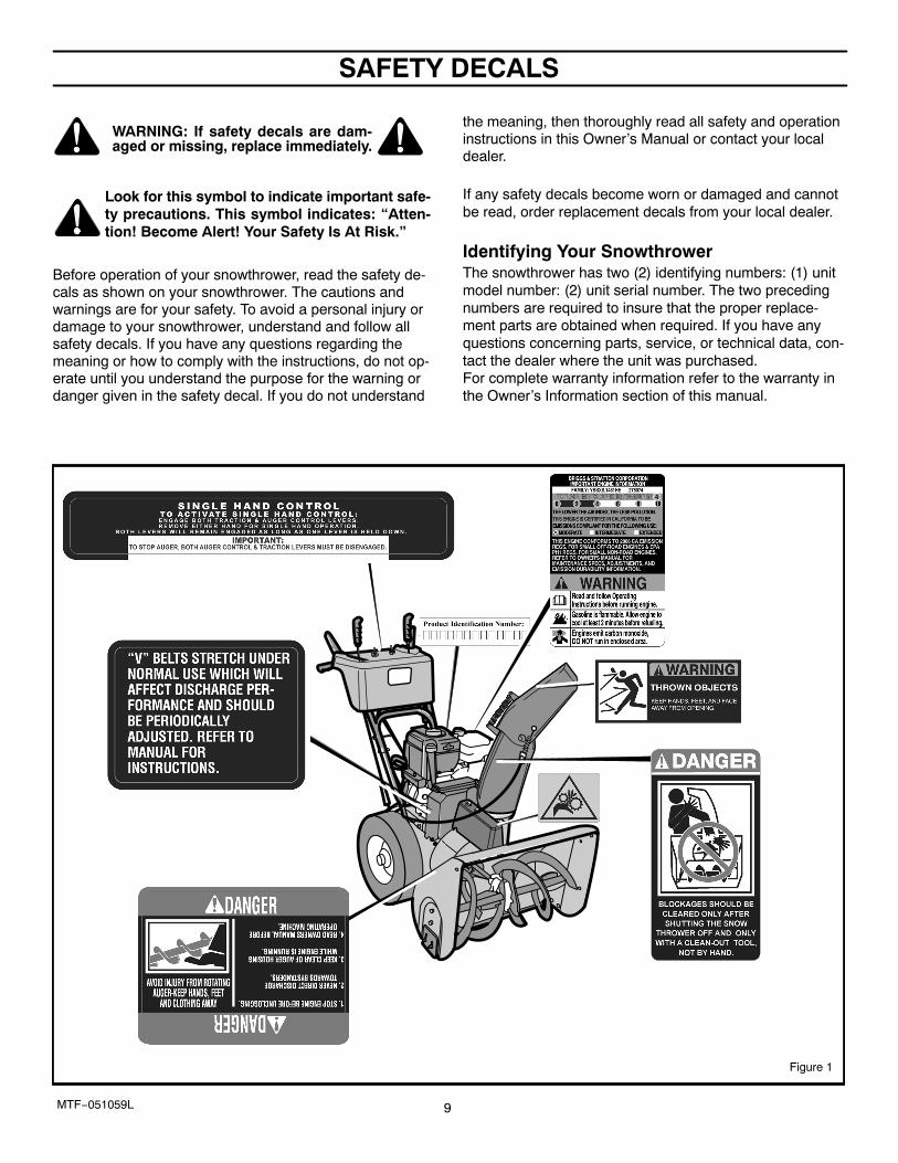
WARNING: If safety decals are dam-aged or missing, replace immediately.
Look for this symbol to indicate important safe-ty precautions. This symbol indicates: “Atten-tion! Become Alert! Your Safety Is At Risk.”
Before operation of your snowthrower, read the safety de-cals as shown on your snowthrower. The cautions andwarnings are for your safety. To avoid a personal injury ordamage to your snowthrower, understand and follow allsafety decals. If you have any questions regarding themeaning or how to comply with the instructions, do not op-erate until you understand the purpose for the warning ordanger given in the safety decal. If you do not understand
the meaning, then thoroughly read all safety and operationinstructions in this Owner’s Manual or contact your localdealer.
If any safety decals become worn or damaged and cannotbe read, order replacement decals from your local dealer.
Identifying Your SnowthrowerThe snowthrower has two (2) identifying numbers: (1) unitmodel number: (2) unit serial number. The two precedingnumbers are required to insure that the proper replace-ment parts are obtained when required. If you have anyquestions concerning parts, service, or technical data, con-tact the dealer where the unit was purchased.For complete warranty information refer to the warranty inthe Owner’s Information section of this manual.
Figure 1
OWNER’S INFORMATION
MTF−051059L 10
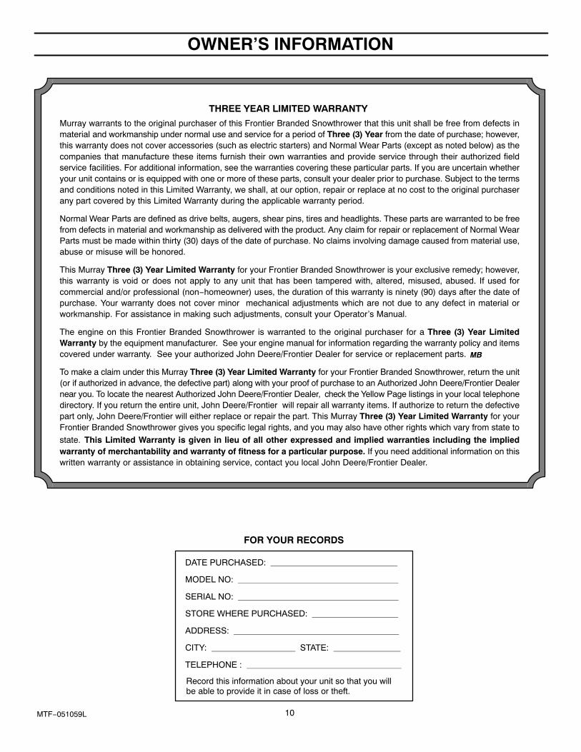
THREE YEAR LIMITED WARRANTY
Murray warrants to the original purchaser of this Frontier Branded Snowthrower that this unit shall be free from defects inmaterial and workmanship under normal use and service for a period of Three (3) Year from the date of purchase; however,this warranty does not cover accessories (such as electric starters) and Normal Wear Parts (except as noted below) as thecompanies that manufacture these items furnish their own warranties and provide service through their authorized fieldservice facilities. For additional information, see the warranties covering these particular parts. If you are uncertain whetheryour unit contains or is equipped with one or more of these parts, consult your dealer prior to purchase. Subject to the termsand conditions noted in this Limited Warranty, we shall, at our option, repair or replace at no cost to the original purchaserany part covered by this Limited Warranty during the applicable warranty period.
Normal Wear Parts are defined as drive belts, augers, shear pins, tires and headlights. These parts are warranted to be freefrom defects in material and workmanship as delivered with the product. Any claim for repair or replacement of Normal WearParts must be made within thirty (30) days of the date of purchase. No claims involving damage caused from material use,abuse or misuse will be honored.
This Murray Three (3) Year Limited Warranty for your Frontier Branded Snowthrower is your exclusive remedy; however,this warranty is void or does not apply to any unit that has been tampered with, altered, misused, abused. If used forcommercial and/or professional (non−homeowner) uses, the duration of this warranty is ninety (90) days after the date ofpurchase. Your warranty does not cover minor mechanical adjustments which are not due to any defect in material orworkmanship. For assistance in making such adjustments, consult your Operator’s Manual.
The engine on this Frontier Branded Snowthrower is warranted to the original purchaser for a Three (3) Year LimitedWarranty by the equipment manufacturer. See your engine manual for information regarding the warranty policy and itemscovered under warranty. See your authorized John Deere/Frontier Dealer for service or replacement parts.
To make a claim under this Murray Three (3) Year Limited Warranty for your Frontier Branded Snowthrower, return the unit(or if authorized in advance, the defective part) along with your proof of purchase to an Authorized John Deere/Frontier Dealernear you. To locate the nearest Authorized John Deere/Frontier Dealer, check the Yellow Page listings in your local telephonedirectory. If you return the entire unit, John Deere/Frontier will repair all warranty items. If authorize to return the defectivepart only, John Deere/Frontier will either replace or repair the part. This Murray Three (3) Year Limited Warranty for yourFrontier Branded Snowthrower gives you specific legal rights, and you may also have other rights which vary from state to
state. This Limited Warranty is given in lieu of all other expressed and implied warranties including the impliedwarranty of merchantability and warranty of fitness for a particular purpose. If you need additional information on thiswritten warranty or assistance in obtaining service, contact you local John Deere/Frontier Dealer.
MB
DATE PURCHASED:
MODEL NO:
SERIAL NO:
STORE WHERE PURCHASED:
ADDRESS:
CITY: STATE:
TELEPHONE :
Record this information about your unit so that you willbe able to provide it in case of loss or theft.
FOR YOUR RECORDS
ASSEMBLY
11MTF−051059L
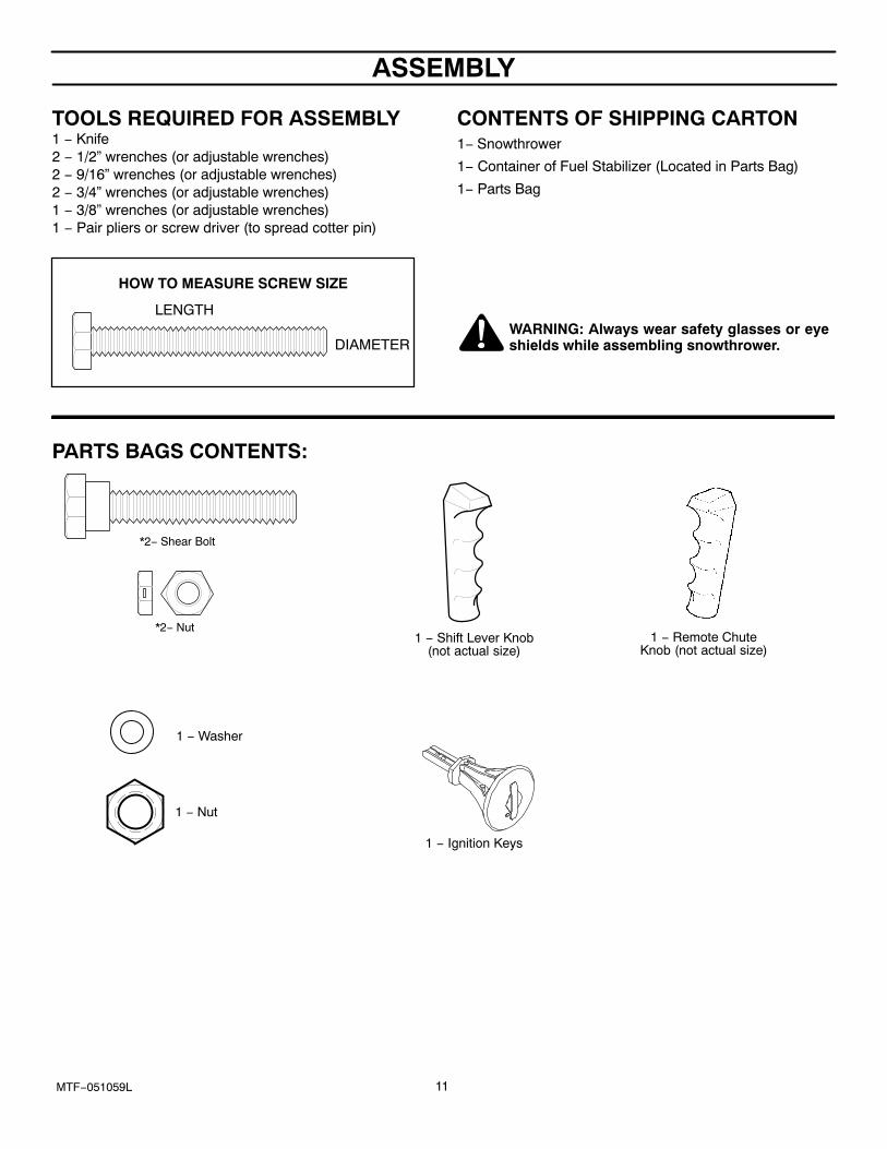
TOOLS REQUIRED FOR ASSEMBLY1 − Knife2 − 1/2” wrenches (or adjustable wrenches)2 − 9/16” wrenches (or adjustable wrenches)2 − 3/4” wrenches (or adjustable wrenches)1 − 3/8” wrenches (or adjustable wrenches)1 − Pair pliers or screw driver (to spread cotter pin)
HOW TO MEASURE SCREW SIZE LENGTH
DIAMETER
CONTENTS OF SHIPPING CARTON1− Snowthrower
1− Container of Fuel Stabilizer (Located in Parts Bag)
1− Parts Bag
WARNING: Always wear safety glasses or eyeshields while assembling snowthrower.
PARTS BAGS CONTENTS:
*2− Shear Bolt
*2− Nut1 − Shift Lever Knob
(not actual size)
1 − Washer
1 − Nut
1 − Remote ChuteKnob (not actual size)
1 − Ignition Keys
ASSEMBLY
12MTF−051059L
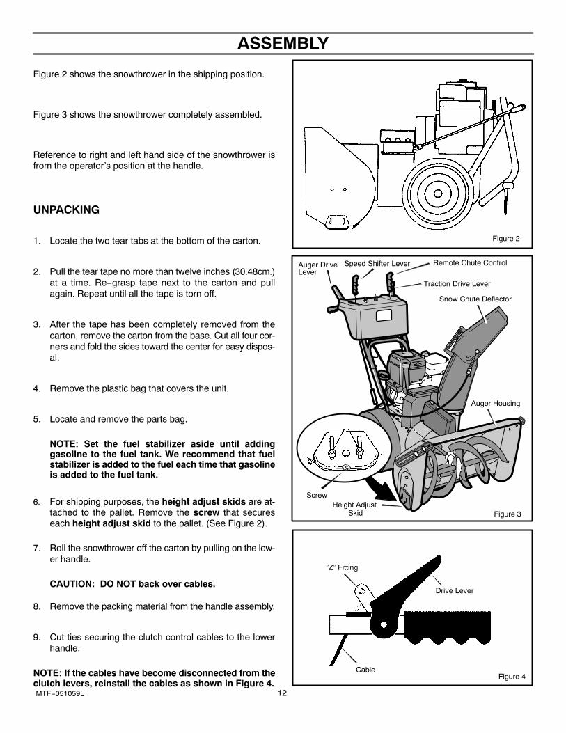
Figure 2 shows the snowthrower in the shipping position.
Figure 3 shows the snowthrower completely assembled.
Reference to right and left hand side of the snowthrower isfrom the operator’s position at the handle.
UNPACKING
1. Locate the two tear tabs at the bottom of the carton.
2. Pull the tear tape no more than twelve inches (30.48cm.)at a time. Re−grasp tape next to the carton and pullagain. Repeat until all the tape is torn off.
3. After the tape has been completely removed from thecarton, remove the carton from the base. Cut all four cor-ners and fold the sides toward the center for easy dispos-al.
4. Remove the plastic bag that covers the unit.
5. Locate and remove the parts bag.
NOTE: Set the fuel stabilizer aside until addinggasoline to the fuel tank. We recommend that fuelstabilizer is added to the fuel each time that gasolineis added to the fuel tank.
6. For shipping purposes, the height adjust skids are at-tached to the pallet. Remove the screw that secureseach height adjust skid to the pallet. (See Figure 2).
7. Roll the snowthrower off the carton by pulling on the low-er handle.
CAUTION: DO NOT back over cables.
8. Remove the packing material from the handle assembly.
9. Cut ties securing the clutch control cables to the lowerhandle.
NOTE: If the cables have become disconnected from theclutch levers, reinstall the cables as shown in Figure 4.
Figure 2
Figure 3
Auger DriveLever
Traction Drive Lever
Snow Chute Deflector
Height Adjust Skid
Auger Housing
Remote Chute Control
Screw
Speed Shifter Lever
Figure 4
”Z” Fitting
Drive Lever
Cable
ASSEMBLY
13MTF−051059L
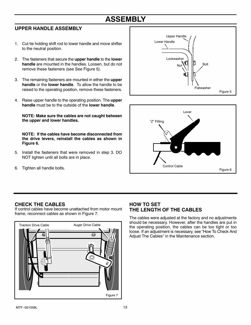
UPPER HANDLE ASSEMBLY
1. Cut tie holding shift rod to lower handle and move shifterto the neutral position.
2. The fasteners that secure the upper handle to the lowerhandle are mounted in the handles. Loosen, but do notremove these fasteners (see See Figure 5).
3. The remaining fasteners are mounted in either the upperhandle or the lower handle. To allow the handle to beraised to the operating position, remove these fasteners.
4. Raise upper handle to the operating position. The upperhandle must be to the outside of the lower handle.
NOTE: Make sure the cables are not caught betweenthe upper and lower handles.
NOTE: If the cables have become disconnected fromthe drive levers, reinstall the cables as shown inFigure 6.
5. Install the fasteners that were removed in step 3. DONOT tighten until all bolts are in place.
6. Tighten all handle bolts.
Figure 5
Nut
Flatwasher
Bolt
Lockwasher
Lower Handle
Upper Handle
Figure 6
Lever
“Z” Fitting
Control Cable
CHECK THE CABLESIf control cables have become unattached from motor mountframe, reconnect cables as shown in Figure 7.
Traction Drive Cable Auger Drive Cable
Figure 7
HOW TO SET THE LENGTH OF THE CABLES
The cables were adjusted at the factory and no adjustmentsshould be necessary. However, after the handles are put inthe operating position, the cables can be too tight or tooloose. If an adjustment is necessary, see “How To Check AndAdjust The Cables” in the Maintenance section.
ASSEMBLY
14MTF−051059L
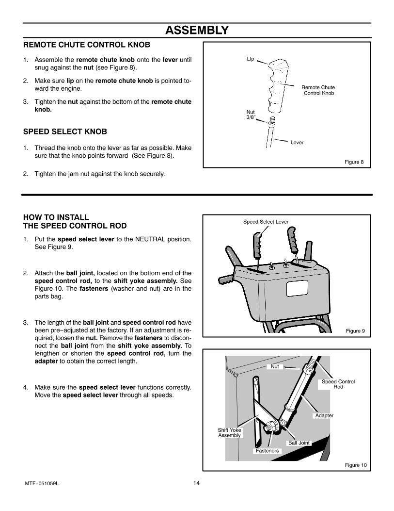
REMOTE CHUTE CONTROL KNOB
1. Assemble the remote chute knob onto the lever untilsnug against the nut (see Figure 8).
2. Make sure lip on the remote chute knob is pointed to-ward the engine.
3. Tighten the nut against the bottom of the remote chuteknob.
SPEED SELECT KNOB
1. Thread the knob onto the lever as far as possible. Makesure that the knob points forward (See Figure 8).
2. Tighten the jam nut against the knob securely.
Figure 8
Remote Chute Control Knob
Nut3/8”
Lever
LIp
HOW TO INSTALL THE SPEED CONTROL ROD
1. Put the speed select lever to the NEUTRAL position.See Figure 9.
2. Attach the ball joint, located on the bottom end of thespeed control rod, to the shift yoke assembly. SeeFigure 10. The fasteners (washer and nut) are in theparts bag.
3. The length of the ball joint and speed control rod havebeen pre−adjusted at the factory. If an adjustment is re-quired, loosen the nut. Remove the fasteners to discon-nect the ball joint from the shift yoke assembly. Tolengthen or shorten the speed control rod, turn theadapter to obtain the correct length.
4. Make sure the speed select lever functions correctly.Move the speed select lever through all speeds.
Speed Select Lever
Figure 9
Figure 10
Ball Joint
Speed ControlRod
Shift YokeAssembly
Fasteners
Nut
Adapter
ASSEMBLY
15MTF−051059L
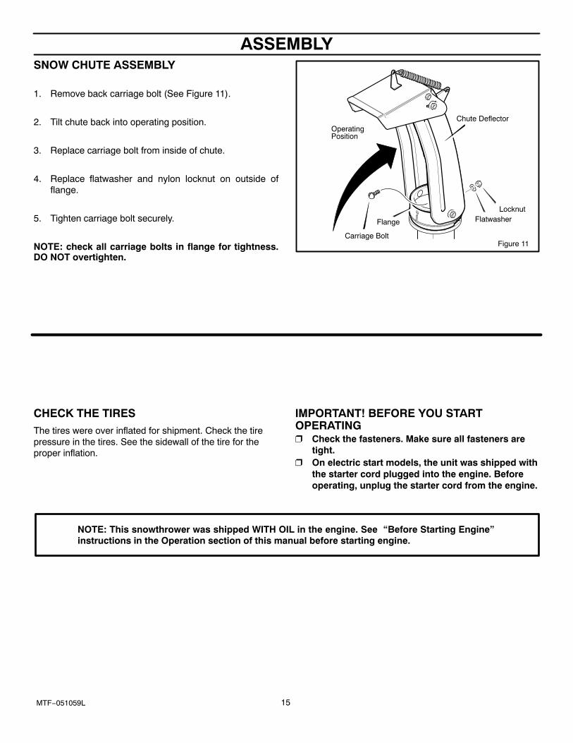
SNOW CHUTE ASSEMBLY
1. Remove back carriage bolt (See Figure 11).
2. Tilt chute back into operating position.
3. Replace carriage bolt from inside of chute.
4. Replace flatwasher and nylon locknut on outside offlange.
5. Tighten carriage bolt securely.
NOTE: check all carriage bolts in flange for tightness.DO NOT overtighten.
Chute DeflectorOperatingPosition
Flange
Carriage Bolt
FlatwasherLocknut
Figure 11
CHECK THE TIRES The tires were over inflated for shipment. Check the tirepressure in the tires. See the sidewall of the tire for theproper inflation.
IMPORTANT! BEFORE YOU STARTOPERATING� Check the fasteners. Make sure all fasteners are
tight.� On electric start models, the unit was shipped with
the starter cord plugged into the engine. Beforeoperating, unplug the starter cord from the engine.
NOTE: This snowthrower was shipped WITH OIL in the engine. See “Before Starting Engine”instructions in the Operation section of this manual before starting engine.
OPERATION
16MTF−051059L
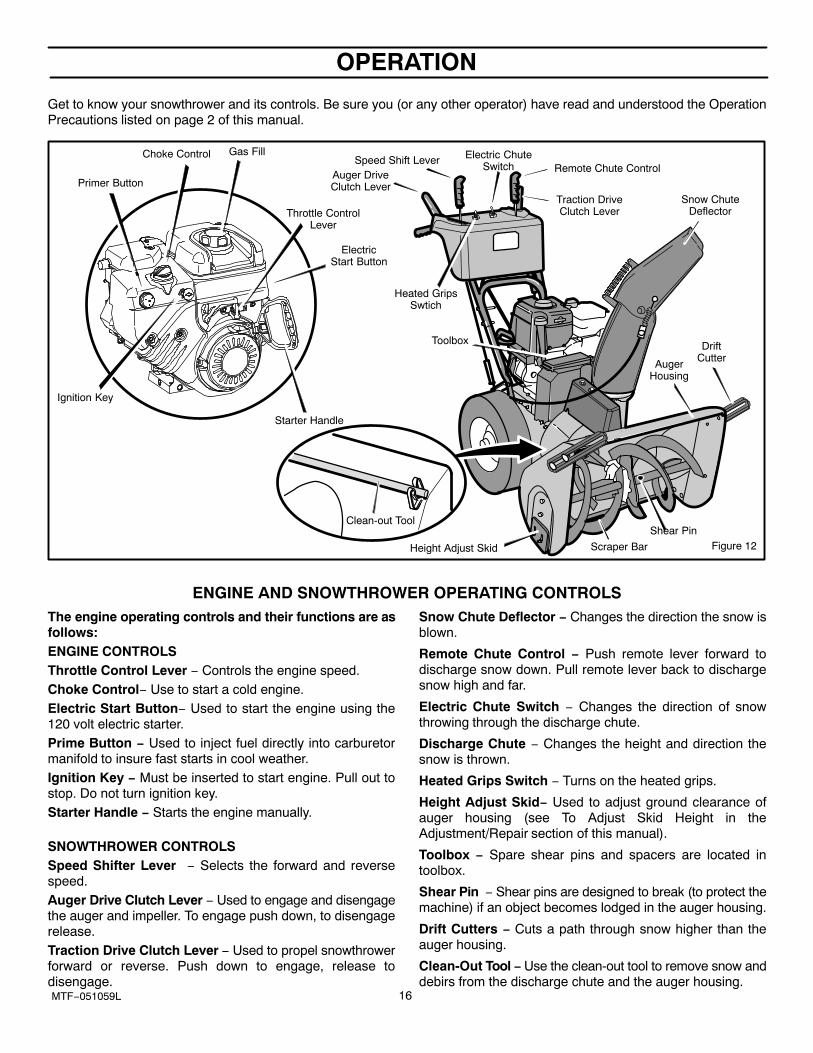
Get to know your snowthrower and its controls. Be sure you (or any other operator) have read and understood the OperationPrecautions listed on page 2 of this manual.
Figure 12
Electric ChuteSwitch
Auger DriveClutch Lever
Traction DriveClutch Lever
Speed Shift Lever
Snow ChuteDeflector
AugerHousing
Height Adjust Skid
Toolbox
Remote Chute Control
DriftCutter
Primer Button
Gas Fill
Starter Handle
Throttle ControlLever
Ignition Key
Choke Control
Scraper Bar
Shear Pin
ElectricStart Button
Heated GripsSwtich
Clean-out Tool
ENGINE AND SNOWTHROWER OPERATING CONTROLSThe engine operating controls and their functions are asfollows:ENGINE CONTROLSThrottle Control Lever − Controls the engine speed.Choke Control− Use to start a cold engine.Electric Start Button− Used to start the engine using the120 volt electric starter.Prime Button − Used to inject fuel directly into carburetormanifold to insure fast starts in cool weather.Ignition Key − Must be inserted to start engine. Pull out tostop. Do not turn ignition key.Starter Handle − Starts the engine manually.
SNOWTHROWER CONTROLSSpeed Shifter Lever − Selects the forward and reversespeed.Auger Drive Clutch Lever − Used to engage and disengagethe auger and impeller. To engage push down, to disengagerelease.Traction Drive Clutch Lever − Used to propel snowthrowerforward or reverse. Push down to engage, release todisengage.
Snow Chute Deflector − Changes the direction the snow isblown.
Remote Chute Control − Push remote lever forward todischarge snow down. Pull remote lever back to dischargesnow high and far.
Electric Chute Switch − Changes the direction of snowthrowing through the discharge chute.
Discharge Chute − Changes the height and direction thesnow is thrown.
Heated Grips Switch − Turns on the heated grips.
Height Adjust Skid− Used to adjust ground clearance ofauger housing (see To Adjust Skid Height in theAdjustment/Repair section of this manual).
Toolbox − Spare shear pins and spacers are located intoolbox.
Shear Pin − Shear pins are designed to break (to protect themachine) if an object becomes lodged in the auger housing.
Drift Cutters − Cuts a path through snow higher than theauger housing.
Clean-Out Tool − Use the clean-out tool to remove snow anddebirs from the discharge chute and the auger housing.
OPERATION
17MTF−051059L
The operation of any snowthrower can result in foreign objects being thrown into the eyes,which canresult in severe eye damage. Always wear safety glasses or eye shields before beginning snowthrowerOperation. We recommend standard safety glasses or Wide Vision Safety Mask for over spectacles.
SNOWTHROWER OPERATION
The most effective use of the snowthrower will be establishedby experience, taking into consideration the terrain, windconditions and building location which will determine thedirection of the discharge chute.
NOTE: Do not blow snow towards a building as hiddenobjects could be blown with sufficient force to causedamage.
TO STOP YOUR SNOWTHROWER
1. To stop throwing snow, release the auger drive lever.See Figure 13.
2. To stop the wheels, release the traction drive lever.
3. To stop the engine, push the throttle control lever to offand pull out the ignition key.
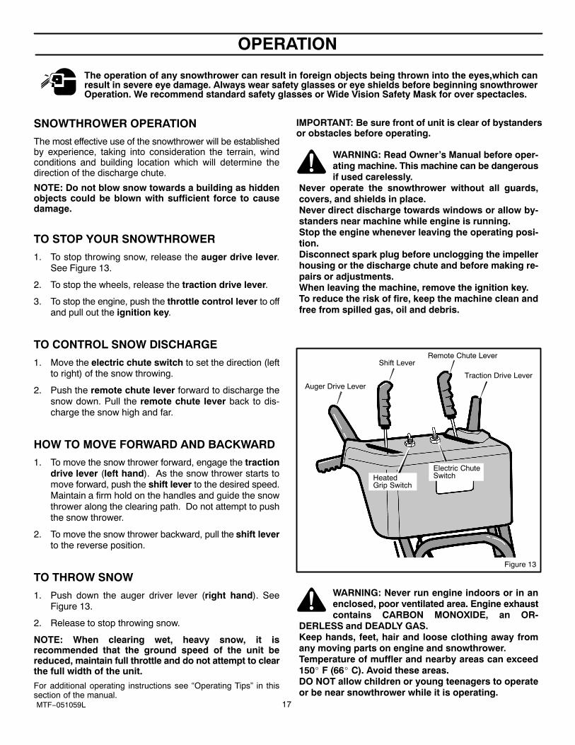
TO CONTROL SNOW DISCHARGE
1. Move the electric chute switch to set the direction (leftto right) of the snow throwing.
2. Push the remote chute lever forward to discharge thesnow down. Pull the remote chute lever back to dis-charge the snow high and far.
HOW TO MOVE FORWARD AND BACKWARD
1. To move the snow thrower forward, engage the tractiondrive lever (left hand). As the snow thrower starts tomove forward, push the shift lever to the desired speed.Maintain a firm hold on the handles and guide the snowthrower along the clearing path. Do not attempt to pushthe snow thrower.
2. To move the snow thrower backward, pull the shift leverto the reverse position.
TO THROW SNOW
1. Push down the auger driver lever (right hand). SeeFigure 13.
2. Release to stop throwing snow.
NOTE: When clearing wet, heavy snow, it isrecommended that the ground speed of the unit bereduced, maintain full throttle and do not attempt to clearthe full width of the unit.
For additional operating instructions see “Operating Tips” in thissection of the manual.
IMPORTANT: Be sure front of unit is clear of bystandersor obstacles before operating.
WARNING: Read Owner’s Manual before oper-ating machine. This machine can be dangerousif used carelessly.
Never operate the snowthrower without all guards,covers, and shields in place. Never direct discharge towards windows or allow by-standers near machine while engine is running. Stop the engine whenever leaving the operating posi-tion. Disconnect spark plug before unclogging the impellerhousing or the discharge chute and before making re-pairs or adjustments. When leaving the machine, remove the ignition key. To reduce the risk of fire, keep the machine clean andfree from spilled gas, oil and debris.
Auger Drive LeverTraction Drive Lever
Shift LeverRemote Chute Lever
Electric ChuteSwitchHeated
Grip Switch
Figure 13
WARNING: Never run engine indoors or in anenclosed, poor ventilated area. Engine exhaustcontains CARBON MONOXIDE, an OR-
DERLESS and DEADLY GAS.Keep hands, feet, hair and loose clothing away fromany moving parts on engine and snowthrower.Temperature of muffler and nearby areas can exceed150� F (66� C). Avoid these areas.DO NOT allow children or young teenagers to operateor be near snowthrower while it is operating.
OPERATION
18MTF--051059L
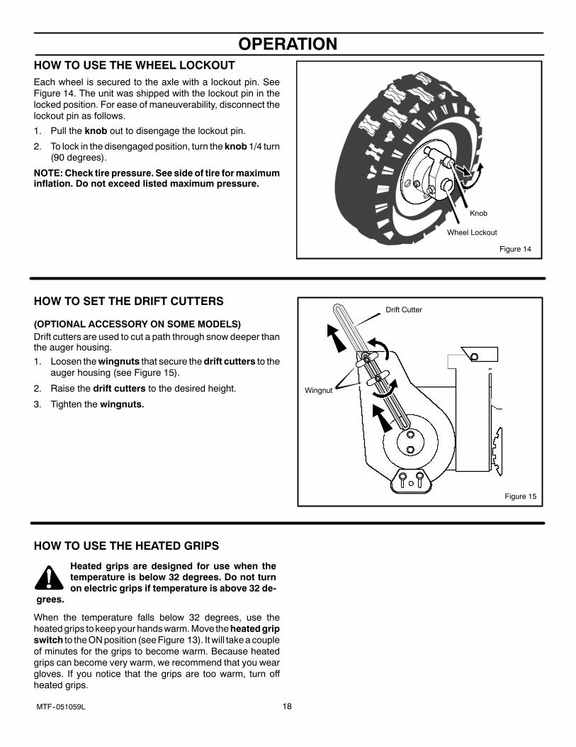
HOW TO USE THE WHEEL LOCKOUTEach wheel is secured to the axle with a lockout pin. SeeFigure 14. The unit was shipped with the lockout pin in thelocked position. For ease of maneuverability, disconnect thelockout pin as follows.
1. Pull the knob out to disengage the lockout pin.
2. To lock in the disengaged position, turn the knob 1/4 turn(90 degrees).
NOTE: Check tire pressure. See side of tire for maximuminflation. Do not exceed listed maximum pressure.
Figure 14
Knob
Wheel Lockout
HOW TO SET THE DRIFT CUTTERS
(OPTIONAL ACCESSORY ON SOME MODELS)Drift cutters are used to cut a path through snow deeper thanthe auger housing.
1. Loosen the wingnuts that secure the drift cutters to theauger housing (see Figure 15).
2. Raise the drift cutters to the desired height.
3. Tighten the wingnuts.
Drift Cutter
Wingnut
Figure 15
HOW TO USE THE HEATED GRIPS
Heated grips are designed for use when thetemperature is below 32 degrees. Do not turnon electric grips if temperature is above 32 de-
grees.
When the temperature falls below 32 degrees, use theheated grips to keep your hands warm. Move the heated gripswitch to the ON position (see Figure 13). It will take a coupleof minutes for the grips to become warm. Because heatedgrips can become very warm, we recommend that you weargloves. If you notice that the grips are too warm, turn offheated grips.
OPERATION
19MTF−051059L
BEFORE STARTING ENGINE
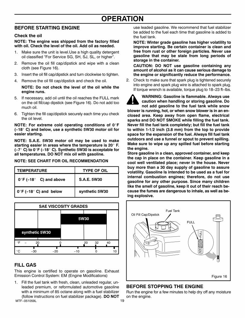
Check the oilNOTE: The engine was shipped from the factory filledwith oil. Check the level of the oil. Add oil as needed.
1. Make sure the unit is level.Use a high quality detergentoil classified “For Service SG, SH, SJ, SL, or higher”.
2. Remove the oil fill cap/dipstick and wipe with a cleancloth (see Figure 16).
3. Insert the oil fill cap/dipstick and turn clockwise to tighten.
4. Remove the oil fill cap/dipstick and check the oil.
NOTE: Do not check the level of the oil while theengine runs.
5. If necessary, add oil until the oil reaches the FULL markon the oil fill/cap dipstick (see Figure 16). Do not add toomuch oil.
6. Tighten the fill cap/dipstick securely each time you checkthe oil level.
NOTE: For extreme cold operating conditions of 0�F(−18� C) and below, use a synthetic 5W30 motor oil foreasier starting.
NOTE: S.A.E. 5W30 motor oil may be used to makestarting easier in areas where the temperature is 20� F.(−7� C) to 0�F (−18� C). Synthetic 5W30 is acceptable forall temperatures. DO NOT mix oil with gasoline.
NOTE: SEE CHART FOR OIL RECOMMENDATION
0�F (−18� C) and below
0�F (−18� C) and above
TYPE OF OILTEMPERATURE
synthetic 5W30
S.A.E. 5W30
�F − 20 0 20 32 40
�C −30 −20 −10 0 10
SAE VISCOSITY GRADES
5W30
synthetic 5W30
FILL GASThis engine is certified to operate on gasoline. ExhaustEmission Control System: EM (Engine Modifications)
1. Fill the fuel tank with fresh, clean, unleaded regular, un-leaded premium, or reformulated automotive gasolinewith a minimum of 85 octane along with a fuel stabilizer(follow instructions on fuel stabilizer package). DO NOT
use leaded gasoline. We recommend that fuel stabilizerbe added to the fuel each time that gasoline is added tothe fuel tank.NOTE: Winter grade gasoline has higher volatility toimprove starting. Be certain container is clean andfree from rust or other foreign particles. Never usegasoline that may be stale from long periods ofstorage in the container.CAUTION: DO NOT use gasoline containing anyamount of alcohol as it can cause serious damage tothe engine or significantly reduce the performance.
2. Check to make sure that spark plug is tightened securelyinto engine and spark plug wire is attached to spark plug.If torque wrench is available, torque plug to 18−23 ft−lbs.
WARNING: Gasoline is flammable. Always usecaution when handling or storing gasoline. Donot add gasoline to the fuel tank while snow
blower is running, hot, or when snow blower is in an en-closed area. Keep away from open flame, electricalsparks and DO NOT SMOKE while filling the fuel tank.Never fill the fuel tank completely; but fill the fuel tankto within 1-1/2 inch (3.8 mm) from the top to providespace for the expansion of the fuel. Always fill fuel tankoutdoors and use a funnel or spout to prevent spilling.Make sure to wipe up any spilled fuel before startingthe engine.Store gasoline in a clean, approved container, and keepthe cap in place on the container. Keep gasoline in acool well ventilated place; never in the house. Neverbuy more than a 30 day supply of gasoline to assurevolatility. Gasoline Is intended to be used as a fuel forinternal combustion engines; therefore, do not usegasoline for any other purpose. Since many childrenlike the smell of gasoline, keep it out of their reach be-cause the fumes are dangerous to inhale, as well as be-ing explosive.
FULL
Figure 16
Oil Fill Cap/DipstickFuel Tank
BEFORE STOPPING THE ENGINERun the engine for a few minutes to help dry off any moistureon the engine.
OPERATION
20MTF−051059L
TO STOP ENGINECAUTION: To stop the engine, do not move the chokecontrol to CHOKE position. Backfire or engine damagecan occur.
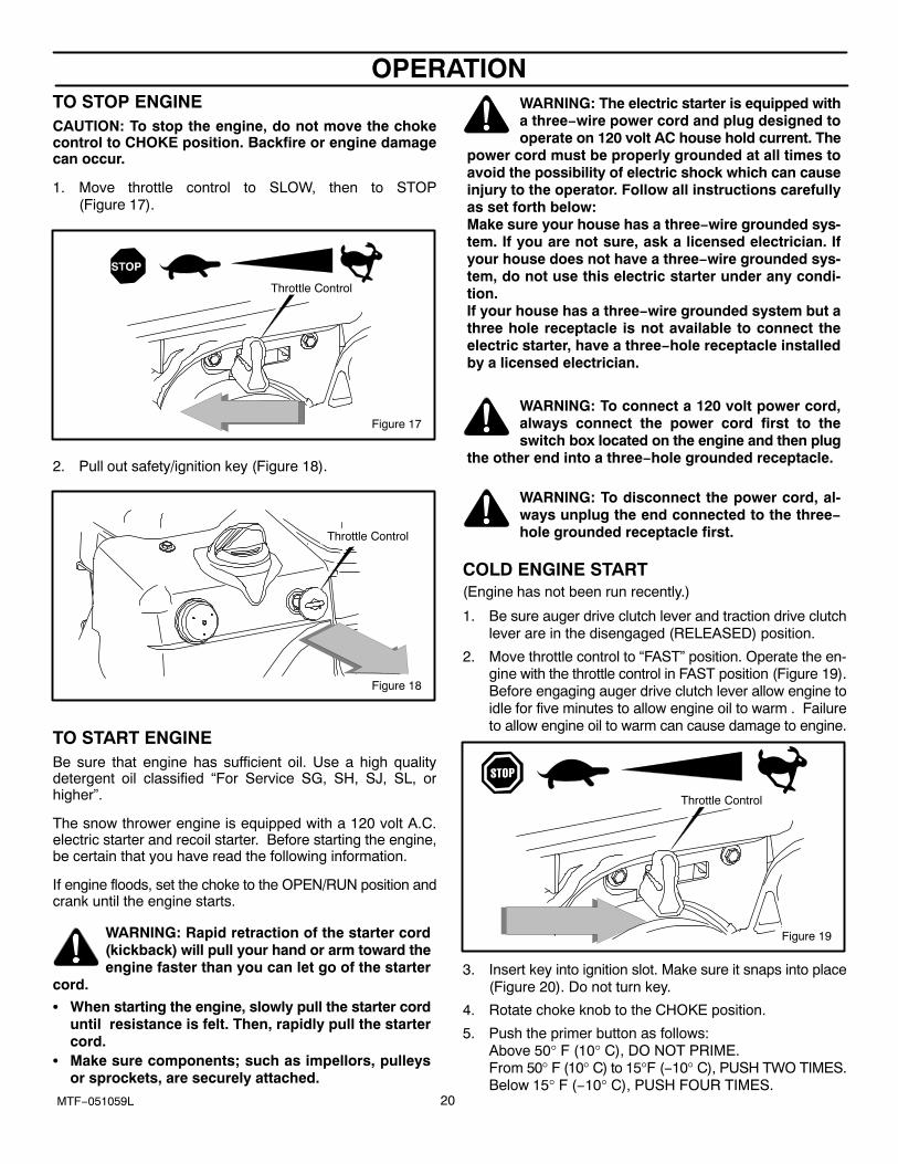
1. Move throttle control to SLOW, then to STOP(Figure 17).
Figure 17
Throttle Control
2. Pull out safety/ignition key (Figure 18).
Figure 18
Throttle Control
TO START ENGINEBe sure that engine has sufficient oil. Use a high qualitydetergent oil classified “For Service SG, SH, SJ, SL, orhigher”.
The snow thrower engine is equipped with a 120 volt A.C.electric starter and recoil starter. Before starting the engine,be certain that you have read the following information.
If engine floods, set the choke to the OPEN/RUN position andcrank until the engine starts.
WARNING: Rapid retraction of the starter cord(kickback) will pull your hand or arm toward theengine faster than you can let go of the starter
cord.
� When starting the engine, slowly pull the starter corduntil resistance is felt. Then, rapidly pull the startercord.
� Make sure components; such as impellors, pulleysor sprockets, are securely attached.
WARNING: The electric starter is equipped witha three−wire power cord and plug designed tooperate on 120 volt AC house hold current. The
power cord must be properly grounded at all times toavoid the possibility of electric shock which can causeinjury to the operator. Follow all instructions carefullyas set forth below:Make sure your house has a three−wire grounded sys-tem. If you are not sure, ask a licensed electrician. Ifyour house does not have a three−wire grounded sys-tem, do not use this electric starter under any condi-tion.If your house has a three−wire grounded system but athree hole receptacle is not available to connect theelectric starter, have a three−hole receptacle installedby a licensed electrician.
WARNING: To connect a 120 volt power cord,always connect the power cord first to theswitch box located on the engine and then plug
the other end into a three−hole grounded receptacle.
WARNING: To disconnect the power cord, al-ways unplug the end connected to the three−hole grounded receptacle first.
COLD ENGINE START(Engine has not been run recently.)
1. Be sure auger drive clutch lever and traction drive clutchlever are in the disengaged (RELEASED) position.
2. Move throttle control to “FAST” position. Operate the en-gine with the throttle control in FAST position (Figure 19).Before engaging auger drive clutch lever allow engine toidle for five minutes to allow engine oil to warm . Failureto allow engine oil to warm can cause damage to engine.
Figure 19
Throttle Control
3. Insert key into ignition slot. Make sure it snaps into place(Figure 20). Do not turn key.
4. Rotate choke knob to the CHOKE position.
5. Push the primer button as follows:Above 50° F (10° C), DO NOT PRIME.From 50° F (10° C) to 15°F (−10° C), PUSH TWO TIMES.Below 15° F (−10° C), PUSH FOUR TIMES.
OPERATION
21MTF−051059L
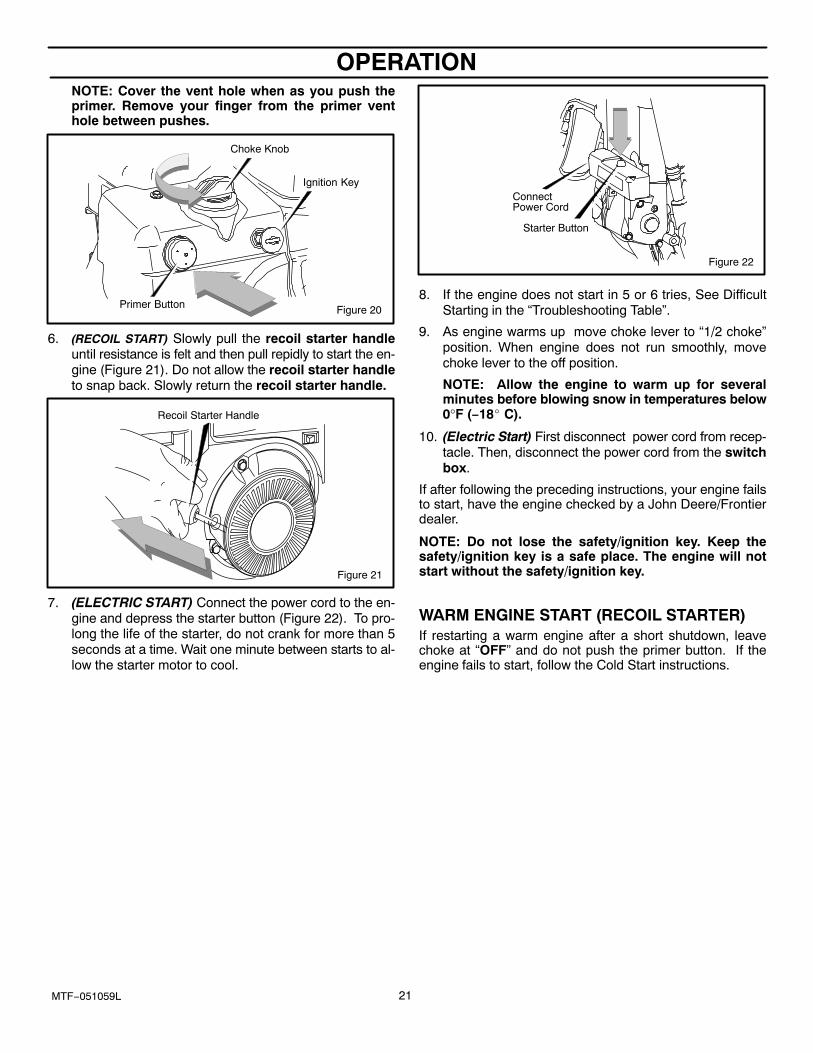
NOTE: Cover the vent hole when as you push theprimer. Remove your finger from the primer venthole between pushes.
Choke Knob
Figure 20Primer Button
Ignition Key
6. (RECOIL START) Slowly pull the recoil starter handleuntil resistance is felt and then pull repidly to start the en-gine (Figure 21). Do not allow the recoil starter handleto snap back. Slowly return the recoil starter handle.
Recoil Starter Handle
Figure 21
7. (ELECTRIC START) Connect the power cord to the en-gine and depress the starter button (Figure 22). To pro-long the life of the starter, do not crank for more than 5seconds at a time. Wait one minute between starts to al-low the starter motor to cool.
Figure 22
Starter Button
ConnectPower Cord
8. If the engine does not start in 5 or 6 tries, See DifficultStarting in the “Troubleshooting Table”.
9. As engine warms up move choke lever to “1/2 choke”position. When engine does not run smoothly, movechoke lever to the off position.
NOTE: Allow the engine to warm up for severalminutes before blowing snow in temperatures below0°F (−18� C).
10. (Electric Start) First disconnect power cord from recep-tacle. Then, disconnect the power cord from the switchbox.
If after following the preceding instructions, your engine failsto start, have the engine checked by a John Deere/Frontierdealer.
NOTE: Do not lose the safety/ignition key. Keep thesafety/ignition key is a safe place. The engine will notstart without the safety/ignition key.
WARM ENGINE START (RECOIL STARTER)If restarting a warm engine after a short shutdown, leavechoke at “OFF” and do not push the primer button. If theengine fails to start, follow the Cold Start instructions.
OPERATION
22MTF−051059L
FROZEN STARTER
If the starter is frozen and will not turn engine:
1. Pull as much rope out of the starter as possible.
2. Release the starter handle and let it snap back againstthe starter. Repeat until the engine starts.
Warm engines will cause condensation in cold weather. Tohelp prevent possible freeze−up of recoil starter and enginecontrols, proceed as follows after each snow removal job.
1. With engine off, allow engine to cool for several minutes.
2. Pull starter rope very slowly until resistance is felt, thenstop. Allow the starter rope to recoil. Repeat three times.
3. With the engine not running, wipe all snow and moisturefrom the carburetor cover in area of control levers. Alsomove choke knob and starter handle several times.
4. With engine not running, wipe all snow and moisture fromcarburetor cover in area of control levers. Also movecontrol levers backward and forward several times.
WARNING: Never run engine indoors or in en-closed, poorly ventilated areas. Engine exhaustcontains CARBON MONOXIDE, AN ODORLESS
AND DEADLY GAS. Keep hands, feet, hair and looseclothing away from any moving parts on engine andsnow thrower.� Engine parts, especially the muffler, become ex-
tremely hot. Severe thermal burns can occur on con-tact. Allow the engine to cool before touching.
� Never allow children to operate the snow thrower.Never allow adults to operate the snow blower with-out proper instruction.
� Keep the area of operation clear of all persons, partic-ularly small children and pets.
� Never leave the snow blower unattended while theengine is running. Anyone operating the engine orequipment must carefully read and understand theoperating instructions.
IMPORTANT: After each use of the snow blower, stop theengine, remove the safetey/ignition key, remove allaccumulated snow from the snow blower and wipeclean. Store the snow blower in a protected area.
NOTE: Never cover snow blower while engine andexhaust area are still warm.
HOW TO CLEAR A CLOGGED DISCHARGE CHUTE
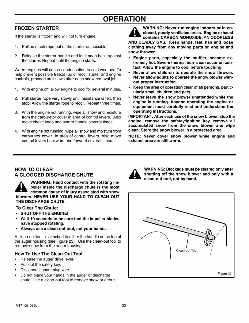
WARNING: Hand contact with the rotating im-peller inside the discharge chute is the mostcommon cause of injury associated with snow
blowers. NEVER USE YOUR HAND TO CLEAN OUTTHE DISCHARGE CHUTE.
To Clear The Chute:� SHUT OFF THE ENGINE!� Wait 10 seconds to be sure that the impeller blades
have stopped rotating.� Always use a clean-out tool, not your hands.
A clean-out tool is attached to either the handle or the top ofthe auger housing (see Figure 23). Use the clean-out tool toremove snow from the auger housing.
How To Use The Clean-Out Tool� Release the auger drive lever.� Pull out the safety key.� Disconnect spark plug wire.� Do not place your hands in the auger or discharge
chute. Use a clean-out tool to remove snow or debris.
WARNING: Blockage must be cleared only aftershutting off the snow blower and only with aclean-out tool, not by hand.
Figure 23
Clean-out Tool
OPERATION
23MTF−051059L
OPERATING TIPS
1. For optimum snow blower efficiency, adjust groundspeed, not the throttle. REMEMBER − if the wheels slip,forward speed will be reduced. The engine is designedto deliver optimum performance at full throttle and mustbe run at this power setting at all times.
2. Most efficient snowblowing is accomplished when snowis removed immediately after it falls.
3. For complete snow removal, slightly overlap each swathpreviously taken.
4. Snow should be discharged downwind whenever pos-sible.
5. For normal usage, set the skids one−eighth inch (3 mm)below the scraper bar. For extremely hard−packed snowsurfaces, the skids may be adjusted upward to insurecleaning efficiency.
6. On gravel or crushed rock surfaces, the skids should beset at 1−1/4 inch (32 mm) below the scraper bar (see ToAdjust Skid Height, in the Adjustment/Repair section inthis manual). Rocks and gravel must not be picked upand thrown by the machine.
7. After the snowblowing job has been completed, allow theengine to idle for a few minutes, to melt snow and ice ac-cumulated on the engine.
8. Clean the snow thrower thoroughly after each use.9. Remove ice and snow accumulation and all debris from
the entire snow thrower, and flush with water (if possible)to remove all salt or other chemicals. Wipe snow throwerdry.
10. Before starting snow blower, always inspect augers andimpeller for ice accumulation and/or debris, which couldresult in snow blower damage.
11. Check oil level before every start. Make sure the oil is atthe FULL mark on the oil fill cap/dipstick.
SERVICE RECOMMENDATIONS
24MTF−051059L
SERVICE RECOMMENDATIONS
PROCEDURE
FIRST2
HOUR
BEFOREEACHUSE OFTEN
EVERY5
HOURS
EVERY10
HOURS
EVERY25
HOURS
BEGINNINGEACH
SEASONBEFORE
STORAGE
SN
Tighten all screws and nuts √ √ √NOW
Auger Drive Belt * √ √WTH Adjust Traction Drive Belt � √ √ � √ � √
ROW
Lubricate Auger Shaft √ √ √WER
Lubricate Chute RotationGear √ √ √
ENG
Oil, Check √ √ √GINE
Oil, Change √ √ √
* Adjust after 2 to 4 hours of use.
� Adjust after First 10 hours and then Every 25 hours of use.
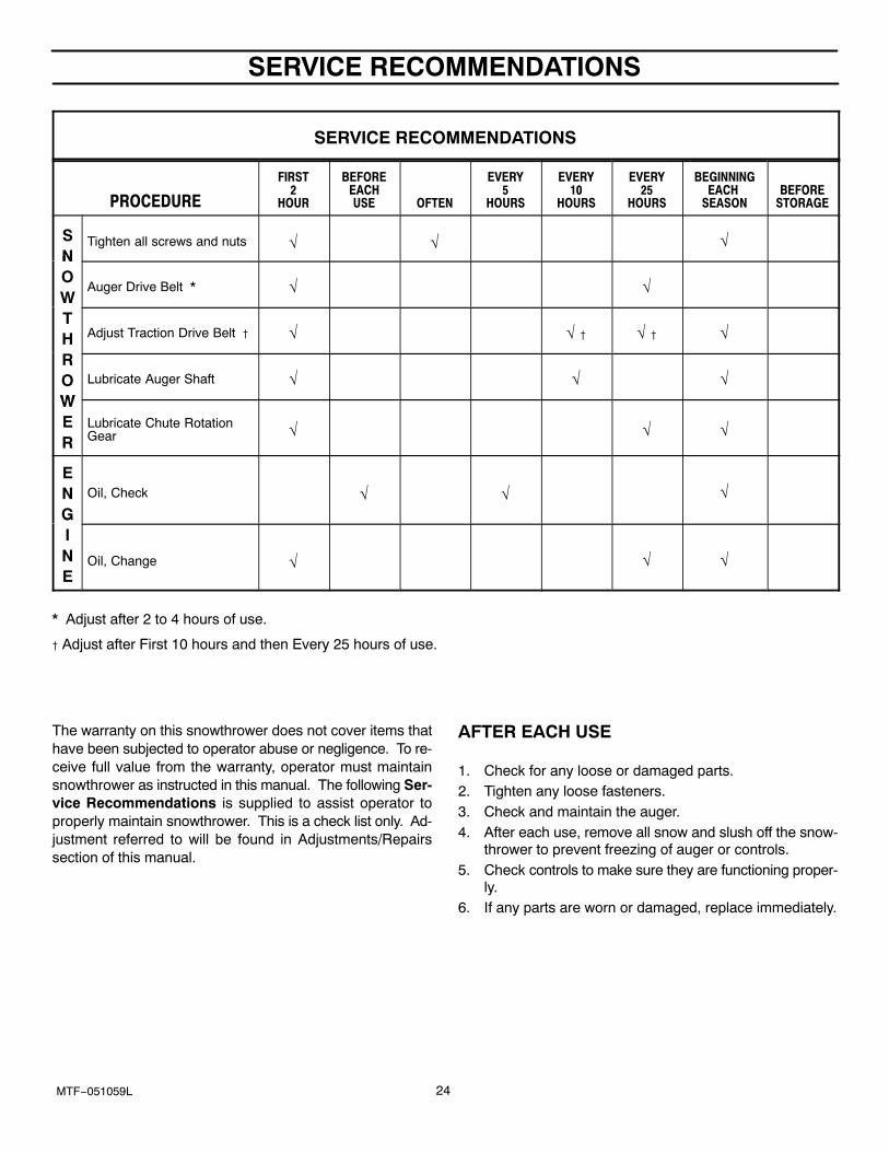
The warranty on this snowthrower does not cover items thathave been subjected to operator abuse or negligence. To re-ceive full value from the warranty, operator must maintainsnowthrower as instructed in this manual. The following Ser-vice Recommendations is supplied to assist operator toproperly maintain snowthrower. This is a check list only. Ad-justment referred to will be found in Adjustments/Repairssection of this manual.
AFTER EACH USE
1. Check for any loose or damaged parts.2. Tighten any loose fasteners.3. Check and maintain the auger.4. After each use, remove all snow and slush off the snow-
thrower to prevent freezing of auger or controls.5. Check controls to make sure they are functioning proper-
ly.6. If any parts are worn or damaged, replace immediately.
MAINTENANCE
25MTF−051059L
Some adjustments will need to be made periodically toproperly maintain your snowthrower.
All adjustments in the MAINTENANCE section of this manualshould be checked at least once each season.
SNOWTHROWERThe following adjustment should be performed more thanonce each season.
Auger and Traction Drive Belts should be adjusted after thefirst 2 to 4 hours of use, again about mid−season and twiceeach season thereafter (See To Adjust Belts paragraph in theMAINTENANCE section).
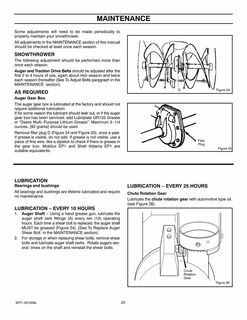
AS REQUIREDAuger Gear Box
The auger gear box is lubricated at the factory and should notrequire additional lubrication. If for some reason the lubricant should leak out, or if the augergear box has been serviced, add Lubriplate GR132 Greaseor “Deere Multi−Purpose Lithium Grease”. Maximum 3−1/4ounces, (92 grams) should be used.
Remove filler plug D (Figure 24 and Figure 25), once a year.If grease is visible, do not add. If grease is not visible, use apiece of fine wire, like a dipstick to check if there is grease inthe gear box. Mobilux EP1 and Shell Aldania EP1 aresuitable equivalents.
Figure 24D
Figure 25
FillerPlug
LUBRICATIONBearings and bushings
All bearings and bushings are lifetime lubricated and requireno maintenance.
LUBRICATION − EVERY 10 HOURS1. Auger Shaft − Using a hand grease gun, lubricate the
auger shaft zerk fittings (A) every ten (10) operatinghours. Each time a shear bolt is replaced, the auger shaftMUST be greased (Figure 24). (See To Replace AugerShear Bolt in the MAINTENANCE section).
2. For storage or when replacing shear bolts, remove shearbolts and lubricate auger shaft zerks. Rotate augers sev-eral times on the shaft and reinstall the shear bolts.
LUBRICATION − EVERY 25 HOURSChute Rotation GearLubricate the chute rotation gear with automotive type oil.(see Figure 26).
ChuteRotationGear
Figure 26
MAINTENANCE
26MTF−051059L
ENGINE
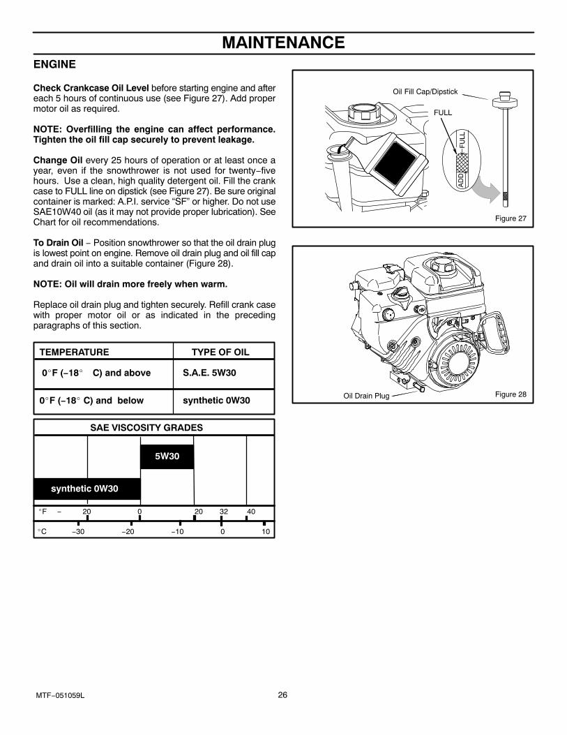
Check Crankcase Oil Level before starting engine and aftereach 5 hours of continuous use (see Figure 27). Add propermotor oil as required.
NOTE: Overfilling the engine can affect performance.Tighten the oil fill cap securely to prevent leakage.
Change Oil every 25 hours of operation or at least once ayear, even if the snowthrower is not used for twenty−fivehours. Use a clean, high quality detergent oil. Fill the crankcase to FULL line on dipstick (see Figure 27). Be sure originalcontainer is marked: A.P.I. service “SF” or higher. Do not useSAE10W40 oil (as it may not provide proper lubrication). SeeChart for oil recommendations.
To Drain Oil − Position snowthrower so that the oil drain plugis lowest point on engine. Remove oil drain plug and oil fill capand drain oil into a suitable container (Figure 28).
NOTE: Oil will drain more freely when warm.
Replace oil drain plug and tighten securely. Refill crank casewith proper motor oil or as indicated in the precedingparagraphs of this section.
0�F (−18� C) and below
0�F (−18� C) and above
TYPE OF OILTEMPERATURE
synthetic 0W30
S.A.E. 5W30
�F − 20 0 20 32 40
�C −30 −20 −10 0 10
SAE VISCOSITY GRADES
5W30
synthetic 0W30
FULL
Oil Fill Cap/Dipstick
Figure 27
Figure 28Oil Drain Plug
MAINTENANCE
27MTF−051059L
WARNING: Always turn unit off, remove igni-tion key and disconnect the spark plug wire be-fore making any repairs or adjustments.
AUGER HOUSING HEIGHT ADJUSTMENT
TO ADJUST SCRAPER BARAfter considerable use, the metal scraper bar will have adefinite wear pattern. The scraper bar in conjunction with theskids should always be adjusted to allow one−eighth of aninch (3 mm) between the scraper bar and the sidewalk orarea to be cleaned.
To adjust the scraper bar, proceed as follows:
1. Position the snowthrower on a level surface.
2. Loosen the carriage bolts and nuts securing the scraperbar to the auger housing.
3. Adjust the scraper bar to the proper position. Tighten thecarriage bolts and nuts, insuring that the scraper bar isparallel with the working surface.
4. For extended operation, the scraper bar may be re-versed. If the scraper bar must be replaced because ofwear, remove the carriage bolts and nuts and install anew scraper bar.
TO ADJUST SKID HEIGHTThis snowthrower is equipped with two height adjust skids,secured to the outside of the auger housing. These elevatethe front of the snowthrower.
When removing snow from a hard surface area such as apaved driveway or walk, adjust the skids up to bring the frontof the snowthrower down.
When removing snow from rock or uneven construction,raise the front of the snowthrower by moving the skids down.This will help to prevent rocks and other debris from beingpicked up and thrown by the augers.
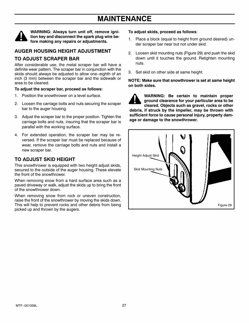
To adjust skids, proceed as follows:
1. Place a block (equal to height from ground desired) un-der scraper bar near but not under skid.
2. Loosen skid mounting nuts (Figure 29) and push the skiddown until it touches the ground. Retighten mountingnuts.
3. Set skid on other side at same height.
NOTE: Make sure that snowthrower is set at same heighton both sides.
WARNING: Be certain to maintain properground clearance for your particular area to becleared. Objects such as gravel, rocks or other
debris, if struck by the impeller, may be thrown withsufficient force to cause personal injury, property dam-age or damage to the snowthrower.
Figure 29
Skid Mounting Nuts
Height Adjust Skid
MAINTENANCE
28MTF−051059L
HOW TO REMOVE THE SNOW HOOD
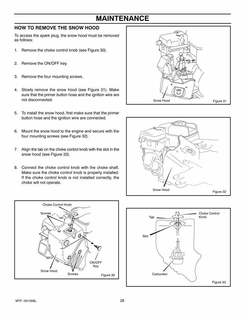
To access the spark plug, the snow hood must be removedas follows:
1. Remove the choke control knob (see Figure 30).
2. Remove the ON/OFF key.
3. Remove the four mounting screws.
4. Slowly remove the snow hood (see Figure 31). Makesure that the primer button hose and the ignition wire arenot disconnected.
5. To install the snow hood, first make sure that the primerbutton hose and the ignition wire are connected.
6. Mount the snow hood to the engine and secure with thefour mounting screws (see Figure 32).
7. Align the tab on the choke control knob with the slot in thesnow hood (see Figure 33).
8. Connect the choke control knob with the choke shaft.Make sure the choke control knob is properly installed.If the choke control knob is not installed correctly, thechoke will not operate.
Figure 30
Choke Control Knob
Screws
Screws
Snow Hood
ON/OFFKey
Figure 31Snow Hood
Figure 32Snow Hood
Carburetor
Choke ControlKnobTab
Slot
Figure 33
MAINTENANCE
29MTF−051059L
BELT ADJUSTMENT
Traction Drive Belt
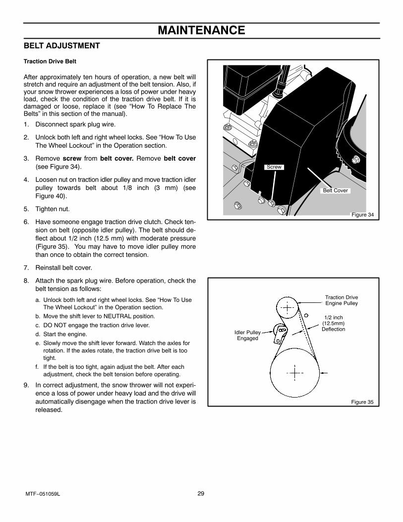
After approximately ten hours of operation, a new belt willstretch and require an adjustment of the belt tension. Also, ifyour snow thrower experiences a loss of power under heavyload, check the condition of the traction drive belt. If it isdamaged or loose, replace it (see “How To Replace TheBelts” in this section of the manual).
1. Disconnect spark plug wire.
2. Unlock both left and right wheel locks. See “How To UseThe Wheel Lockout” in the Operation section.
3. Remove screw from belt cover. Remove belt cover(see Figure 34).
4. Loosen nut on traction idler pulley and move traction idlerpulley towards belt about 1/8 inch (3 mm) (seeFigure 40).
5. Tighten nut.
6. Have someone engage traction drive clutch. Check ten-sion on belt (opposite idler pulley). The belt should de-flect about 1/2 inch (12.5 mm) with moderate pressure(Figure 35). You may have to move idler pulley morethan once to obtain the correct tension.
7. Reinstall belt cover.
8. Attach the spark plug wire. Before operation, check thebelt tension as follows:
a. Unlock both left and right wheel locks. See “How To UseThe Wheel Lockout” in the Operation section.
b. Move the shift lever to NEUTRAL position.
c. DO NOT engage the traction drive lever.
d. Start the engine.
e. Slowly move the shift lever forward. Watch the axles forrotation. If the axles rotate, the traction drive belt is tootight.
f. If the belt is too tight, again adjust the belt. After eachadjustment, check the belt tension before operating.
9. In correct adjustment, the snow thrower will not experi-ence a loss of power under heavy load and the drive willautomatically disengage when the traction drive lever isreleased.
Figure 34
Belt Cover
Screw
Figure 35
Idler PulleyEngaged
Traction DriveEngine Pulley
1/2 inch(12.5mm)Deflection
MAINTENANCE
30MTF−051059L
BELT ADJUSTMENT
Auger Drive Belt
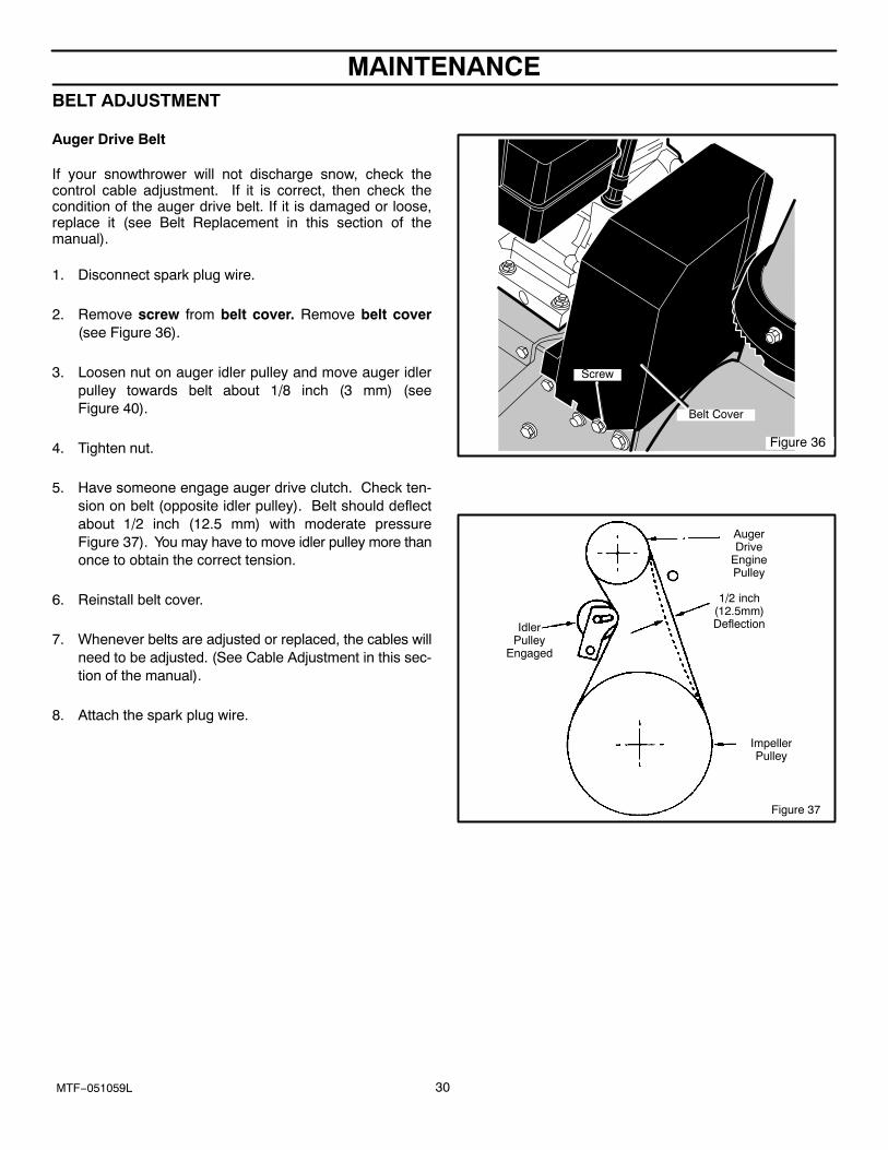
If your snowthrower will not discharge snow, check thecontrol cable adjustment. If it is correct, then check thecondition of the auger drive belt. If it is damaged or loose,replace it (see Belt Replacement in this section of themanual).
1. Disconnect spark plug wire.
2. Remove screw from belt cover. Remove belt cover(see Figure 36).
3. Loosen nut on auger idler pulley and move auger idlerpulley towards belt about 1/8 inch (3 mm) (seeFigure 40).
4. Tighten nut.
5. Have someone engage auger drive clutch. Check ten-sion on belt (opposite idler pulley). Belt should deflectabout 1/2 inch (12.5 mm) with moderate pressureFigure 37). You may have to move idler pulley more thanonce to obtain the correct tension.
6. Reinstall belt cover.
7. Whenever belts are adjusted or replaced, the cables willneed to be adjusted. (See Cable Adjustment in this sec-tion of the manual).
8. Attach the spark plug wire.
Figure 36
Belt Cover
Screw
Figure 37
AugerDrive
EnginePulley
1/2 inch(12.5mm)Deflection
ImpellerPulley
IdlerPulley
Engaged
MAINTENANCE
31MTF−051059L
HOW TO REPLACE THE BELTS
The drive belts are of special construction and must bereplaced with original factory replacement belts availablefrom your nearest authorized service center.Some steps require the assistance of a second person.
How To Remove the Auger Drive BeltIf the auger drive belt is damaged, the snow thrower will notdischarge snow. Replace the damaged belt as follows.1. Disconnect the spark plug wire.
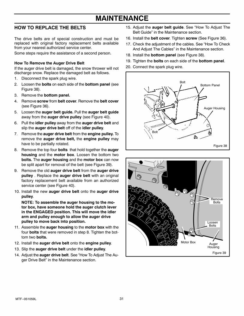
2. Loosen the bolts on each side of the bottom panel (seeFigure 38).
3. Remove the bottom panel.
4. Remove screw from belt cover. Remove the belt cover(see Figure 36).
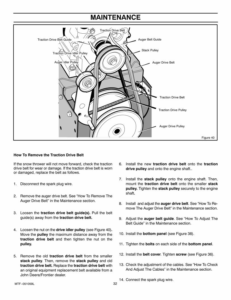
5. Loosen the auger belt guide. Pull the auger belt guideaway from the auger drive pulley (see Figure 40).
6. Pull the idler pulley away from the auger drive belt andslip the auger drive belt off of the idler pulley.
7. Remove the auger drive belt from the engine pulley. Toremove the auger drive belt, the engine pulley mayhave to be partially rotated.
8. Remove the top four bolts that hold together the augerhousing and the motor box. Loosen the bottom twobolts. The auger housing and the motor box can nowbe split apart for removal of the belt (see Figure 39).
9. Remove the old auger drive belt from the auger drivepulley . Replace the auger drive belt with an originalfactory replacement belt available from an authorizedservice center (see Figure 40).
10. Install the new auger drive belt onto the auger drivepulley.
NOTE: To assemble the auger housing to the mo-tor box, have someone hold the auger clutch leverin the ENGAGED position. This will move the idlerarm and pulley enough to allow the auger drivepulley to move back into position.
11. Assemble the auger housing to the motor box with thefour bolts that were removed in step 8. Tighten the bot-tom two bolts.
12. Install the auger drive belt onto the engine pulley.
13. Slip the auger drive belt under the idler pulley.
14. Adjust the auger drive belt. See “How To Adjust The Au-ger Drive Belt” in the Maintenance section.
15. Adjust the auger belt guide. See “How To Adjust TheBelt Guide” in the Maintenance section.
16. Install the belt cover. Tighten screw (See Figure 36).
17. Check the adjustment of the cables. See “How To CheckAnd Adjust The Cables” in the Maintenance section.
18. Install the bottom panel (see Figure 38).
19. Tighten the bolts on each side of the bottom panel.20. Connect the spark plug wire.
Figure 38
Bottom PanelBolt
Auger Housing
Bolt
Figure 39
RemoveBolts
AugerHousing
Motor Box
LoosenBolts
MAINTENANCE
32MTF−051059L
Auger Belt Guide
Stack Pulley
Auger Idler Pulley Auger Drive Belt
Auger Drive Pulley
Figure 40
Traction Drive Belt
Traction Drive Belt
Traction Drive Belt Guide
Traction Drive Pulley
Traction Drive Idler Pulley
How To Remove the Traction Drive Belt
If the snow thrower will not move forward, check the tractiondrive belt for wear or damage. If the traction drive belt is wornor damaged, replace the belt as follows.
1. Disconnect the spark plug wire.
2. Remove the auger drive belt. See “How To Remove TheAuger Drive Belt” in the Maintenance section.
3. Loosen the traction drive belt guide(s). Pull the beltguide(s) away from the traction drive belt.
4. Loosen the nut on the drive idler pulley (see Figure 40).Move the pulley the maximum distance away from thetraction drive belt and then tighten the nut on thepulley.
5. Remove the old traction drive belt from the smallerstack pulley. Then, remove the stack pulley and oldtraction drive belt. Replace the traction drive belt withan original equipment replacement belt available from aJohn Deere/Frontier dealer.
6. Install the new traction drive belt onto the tractiondrive pulley and onto the engine shaft..
7. Install the stack pulley onto the engine shaft. Then,mount the traction drive belt onto the smaller stackpulley. Tighten the stack pulley securely to the engineshaft.
8. Install and adjust the auger drive belt. See “How To Re-move The Auger Drive Belt” in the Maintenance section.
9. Adjust the auger belt guide. See “How To Adjust TheBelt Guide” in the Maintenance section.
10. Install the bottom panel (see Figure 38).
11. Tighten the bolts on each side of the bottom panel.
12. Install the belt cover. Tighten screw (see Figure 36).
13. Check the adjustment of the cables. See “How To CheckAnd Adjust The Cables” in the Maintenance section.
14. Connect the spark plug wire.
MAINTENANCE
33MTF−051059L
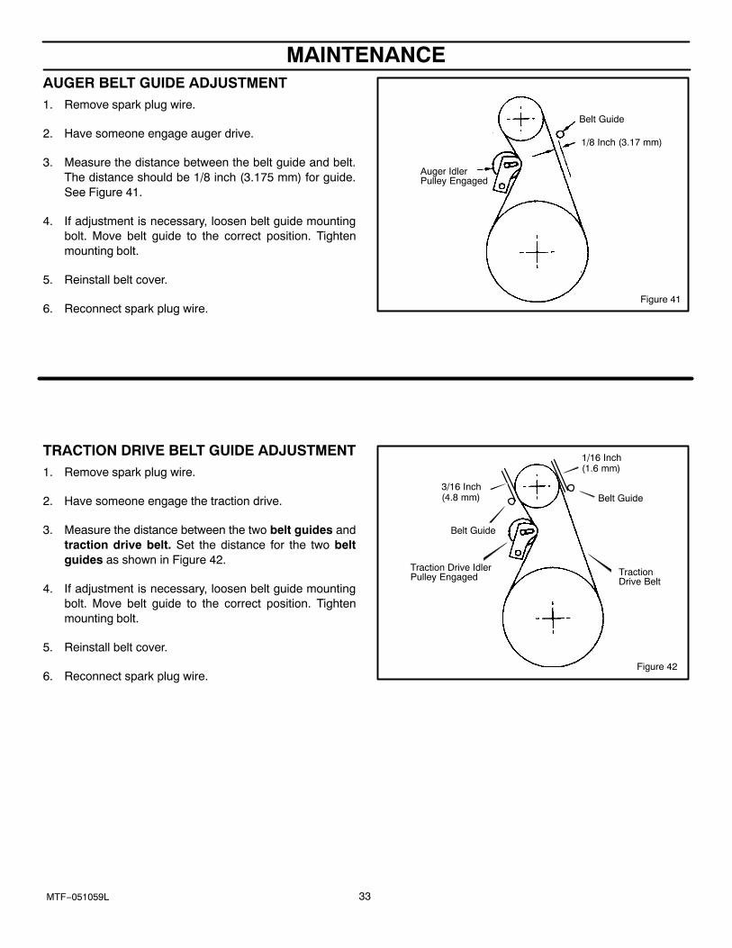
AUGER BELT GUIDE ADJUSTMENT1. Remove spark plug wire.
2. Have someone engage auger drive.
3. Measure the distance between the belt guide and belt.The distance should be 1/8 inch (3.175 mm) for guide.See Figure 41.
4. If adjustment is necessary, loosen belt guide mountingbolt. Move belt guide to the correct position. Tightenmounting bolt.
5. Reinstall belt cover.
6. Reconnect spark plug wire.Figure 41
Belt Guide
1/8 Inch (3.17 mm)
Auger Idler Pulley Engaged
TRACTION DRIVE BELT GUIDE ADJUSTMENT1. Remove spark plug wire.
2. Have someone engage the traction drive.
3. Measure the distance between the two belt guides andtraction drive belt. Set the distance for the two beltguides as shown in Figure 42.
4. If adjustment is necessary, loosen belt guide mountingbolt. Move belt guide to the correct position. Tightenmounting bolt.
5. Reinstall belt cover.
6. Reconnect spark plug wire.Figure 42
Belt Guide
1/16 Inch (1.6 mm)
Traction Drive Idler Pulley Engaged Traction
Drive Belt
3/16 Inch (4.8 mm)
Belt Guide
MAINTENANCE
34MTF−051059L
HOW TO CHECK AND ADJUST THE CABLES The cables are adjusted at the factory and no adjustmentshould be necessary. If the cables have become stretchedor are sagging adjustment will be necessary.
Whenever belts are adjusted or replaced, the cables willneed to be adjusted.
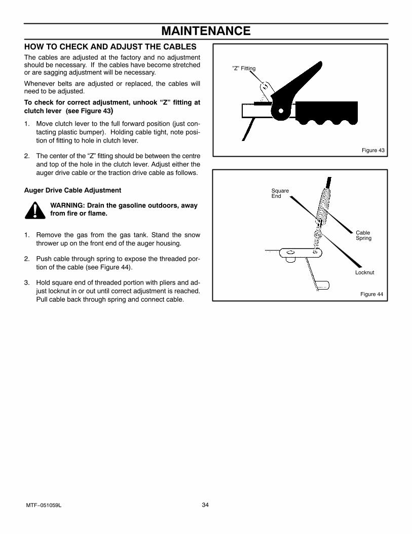
To check for correct adjustment, unhook “Z” fitting atclutch lever (see Figure 43)
1. Move clutch lever to the full forward position (just con-tacting plastic bumper). Holding cable tight, note posi-tion of fitting to hole in clutch lever.
2. The center of the “Z” fitting should be between the centreand top of the hole in the clutch lever. Adjust either theauger drive cable or the traction drive cable as follows.
Auger Drive Cable Adjustment
WARNING: Drain the gasoline outdoors, awayfrom fire or flame.
1. Remove the gas from the gas tank. Stand the snowthrower up on the front end of the auger housing.
2. Push cable through spring to expose the threaded por-tion of the cable (see Figure 44).
3. Hold square end of threaded portion with pliers and ad-just locknut in or out until correct adjustment is reached.Pull cable back through spring and connect cable.
Figure 43
”Z” Fitting
Figure 44
CableSpring
Locknut
SquareEnd
MAINTENANCE
35MTF−051059L
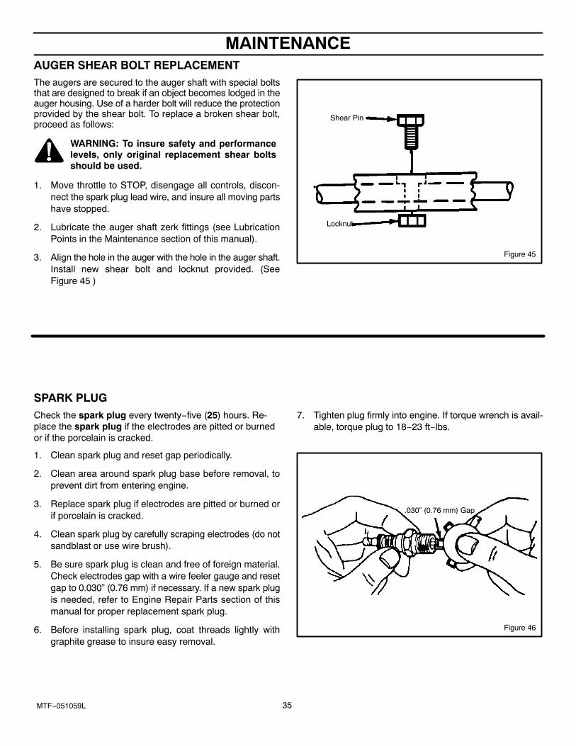
AUGER SHEAR BOLT REPLACEMENTThe augers are secured to the auger shaft with special boltsthat are designed to break if an object becomes lodged in theauger housing. Use of a harder bolt will reduce the protectionprovided by the shear bolt. To replace a broken shear bolt,proceed as follows:
WARNING: To insure safety and performancelevels, only original replacement shear boltsshould be used.
1. Move throttle to STOP, disengage all controls, discon-nect the spark plug lead wire, and insure all moving partshave stopped.
2. Lubricate the auger shaft zerk fittings (see LubricationPoints in the Maintenance section of this manual).
3. Align the hole in the auger with the hole in the auger shaft.Install new shear bolt and locknut provided. (SeeFigure 45 )
Figure 45
Shear Pin
Locknut
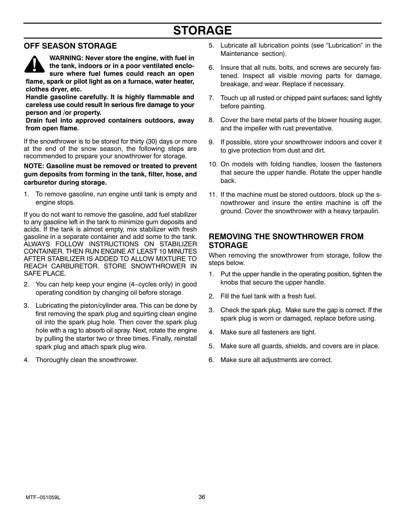
SPARK PLUGCheck the spark plug every twenty−five (25) hours. Re-place the spark plug if the electrodes are pitted or burnedor if the porcelain is cracked.
1. Clean spark plug and reset gap periodically.
2. Clean area around spark plug base before removal, toprevent dirt from entering engine.
3. Replace spark plug if electrodes are pitted or burned orif porcelain is cracked.
4. Clean spark plug by carefully scraping electrodes (do notsandblast or use wire brush).
5. Be sure spark plug is clean and free of foreign material.Check electrodes gap with a wire feeler gauge and resetgap to 0.030” (0.76 mm) if necessary. If a new spark plugis needed, refer to Engine Repair Parts section of thismanual for proper replacement spark plug.
6. Before installing spark plug, coat threads lightly withgraphite grease to insure easy removal.
7. Tighten plug firmly into engine. If torque wrench is avail-able, torque plug to 18−23 ft−lbs.
Figure 46
.030” (0.76 mm) Gap
STORAGE
36MTF−051059L
OFF SEASON STORAGEWARNING: Never store the engine, with fuel inthe tank, indoors or in a poor ventilated enclo-sure where fuel fumes could reach an open
flame, spark or pilot light as on a furnace, water heater,clothes dryer, etc.Handle gasoline carefully. It is highly flammable andcareless use could result In serious fire damage to yourperson and /or property.Drain fuel into approved containers outdoors, awayfrom open flame.
If the snowthrower is to be stored for thirty (30) days or moreat the end of the snow season, the following steps arerecommended to prepare your snowthrower for storage.
NOTE: Gasoline must be removed or treated to preventgum deposits from forming in the tank, filter, hose, andcarburetor during storage.
1. To remove gasoline, run engine until tank is empty andengine stops.
If you do not want to remove the gasoline, add fuel stabilizerto any gasoline left in the tank to minimize gum deposits andacids. If the tank is almost empty, mix stabilizer with freshgasoline in a separate container and add some to the tank.ALWAYS FOLLOW INSTRUCTIONS ON STABILIZERCONTAINER. THEN RUN ENGINE AT LEAST 10 MINUTESAFTER STABILIZER IS ADDED TO ALLOW MIXTURE TOREACH CARBURETOR. STORE SNOWTHROWER INSAFE PLACE.
2. You can help keep your engine (4−cycles only) in goodoperating condition by changing oil before storage.
3. Lubricating the piston/cylinder area. This can be done byfirst removing the spark plug and squirting clean engineoil into the spark plug hole. Then cover the spark plughole with a rag to absorb oil spray. Next, rotate the engineby pulling the starter two or three times. Finally, reinstallspark plug and attach spark plug wire.
4. Thoroughly clean the snowthrower.
5. Lubricate all lubrication points (see “Lubrication“ in theMaintenance section).
6. Insure that all nuts, bolts, and screws are securely fas-tened. Inspect all visible moving parts for damage,breakage, and wear. Replace if necessary.
7. Touch up all rusted or chipped paint surfaces; sand lightlybefore painting.
8. Cover the bare metal parts of the blower housing auger,and the impeller with rust preventative.
9. If possible, store your snowthrower indoors and cover itto give protection from dust and dirt.
10. On models with folding handles, loosen the fastenersthat secure the upper handle. Rotate the upper handleback.
11. If the machine must be stored outdoors, block up the s-nowthrower and insure the entire machine is off theground. Cover the snowthrower with a heavy tarpaulin.
REMOVING THE SNOWTHROWER FROMSTORAGEWhen removing the snowthrower from storage, follow thesteps below.
1. Put the upper handle in the operating position, tighten theknobs that secure the upper handle.
2. Fill the fuel tank with a fresh fuel.
3. Check the spark plug. Make sure the gap is correct. If thespark plug is worn or damaged, replace before using.
4. Make sure all fasteners are tight.
5. Make sure all guards, shields, and covers are in place.
6. Make sure all adjustments are correct.

TROUBLE SHOOTING CHART
37MTF−051059L
PROBLEM LOOK FOR REMEDY
Difficult starting Defective spark plug. Replace defective spark plug.
Engine runs erratically Blocked fuel line. Clean fuel line.
Empty gas tank. Check fuel supply,
Stale gasoline. Add fresh gasoline with fuel stabilizer.
Water or dirt in fuel system. Remove carburetor bowl to drain fuel tank. Refillwith fresh fuel. CAUTION: Do not removecarburetor bowl when the engine is hot.
Engine stalls Unit running on CHOKE. Set choke lever to RUN position.
Loss of power Gas cap vent hole is plugged. Remove ice and snow from cap. Be sure venthole is clear.
Electric Grips do notheat;Electric Chute doesnot rotate
Blown fuse Check the fuse. Replace the fuse with a 7.5 ampautomative type fuse. See the Wiring Harnessparts list page for the location of the fuse.
Excessive vibration Loose parts or damaged impeller. Stop engine immediately and remove spark plugwire. Tighten all bolts and make all necessaryrepairs. If vibration continues, have the unitserviced by a competent repairman.
Unit fails to propelitself
Drive belt loose or damaged. Replace drive belt. Refer to Drive BeltReplacement in Maintenance section of thismanual.
Incorrect adjustment of traction drivecable.
Adjust traction drive cable. Refer to CableAdjustment in Maintenance section of thismanual.
Unit fails to dischargesnow
Auger drive belt loose or damaged. Replace or adjust auger drive belt. Refer to DriveBelt Replacement and Drive Belt Adjustment inMaintenance section of this manual.
Auger control cable not adjustedcorrectly.
Adjust auger control cable. Refer to CableAdjustment in Maintenance section of thismanual.
Broken shear bolt. Replace shear bolt. Refer to Auger Shear BoltReplacement in Maintenance section of thismanual.
Discharge chute clogged. Stop engine immediately and disconnect sparkplug wire. Refer to the first Warning inSnowthrower Operation in Operation section ofthis manual. Clean discharge chute and inside ofauger housing.
Foreign object lodged in auger. Stop engine immediately and disconnect sparkplug wire. Refer to the third Warning inSnowthrower Operation in Operation section ofthis manual. Remove object from auger.
Identifying Your SnowthrowerYour new Snowthrower has two (2) identifying numbers: (1) unit model number: (2) unit serial number. The two precedingnumbers are required to insure that the proper replacement parts are obtained when required. If you have any questionsconcerning parts, service, or technical data, contact your nearest John Deere/Frontier dealer.For complete warranty information refer to the warranty in the Owner’s Information section of this manual.

NOTES
38MTF−051059L

NOTES
39MTF−051059L
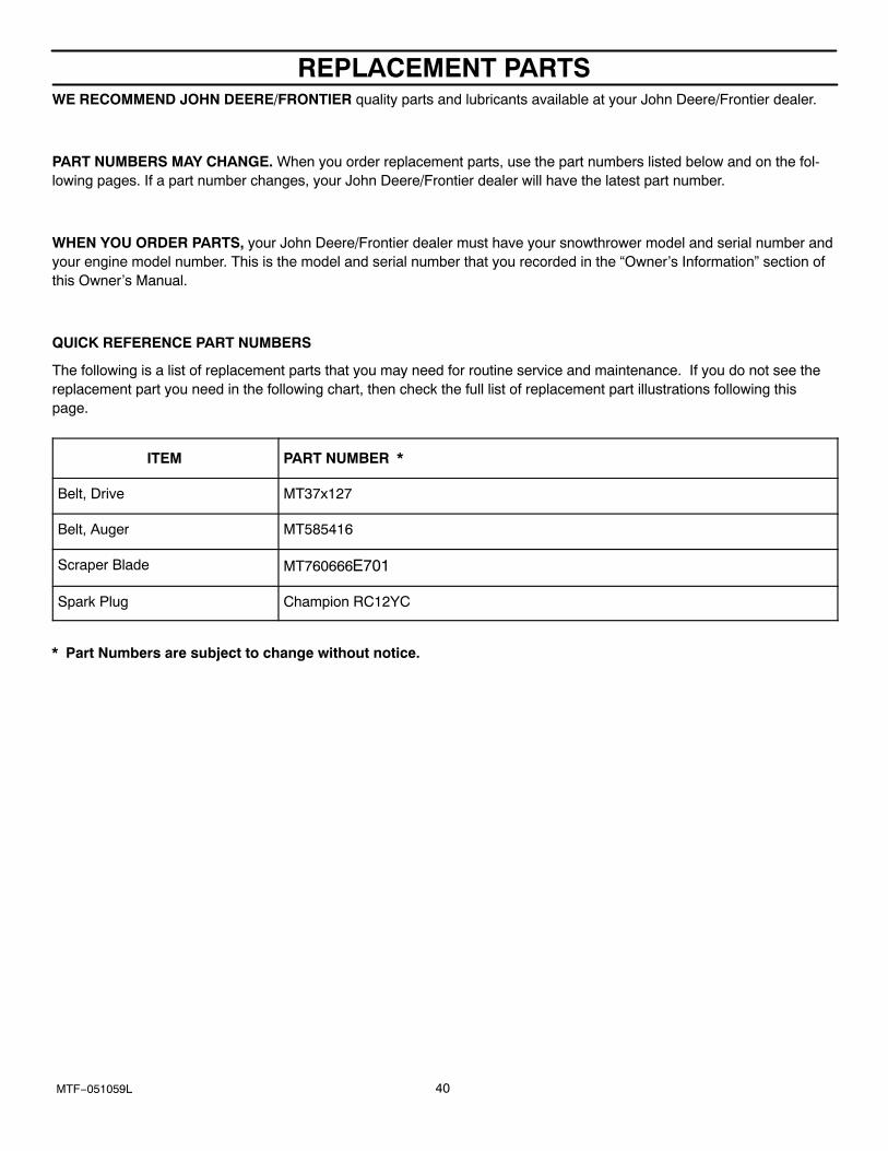
REPLACEMENT PARTS
40MTF−051059L
WE RECOMMEND JOHN DEERE/FRONTIER quality parts and lubricants available at your John Deere/Frontier dealer.
PART NUMBERS MAY CHANGE. When you order replacement parts, use the part numbers listed below and on the fol-lowing pages. If a part number changes, your John Deere/Frontier dealer will have the latest part number.
WHEN YOU ORDER PARTS, your John Deere/Frontier dealer must have your snowthrower model and serial number andyour engine model number. This is the model and serial number that you recorded in the “Owner’s Information” section ofthis Owner’s Manual.
QUICK REFERENCE PART NUMBERS
The following is a list of replacement parts that you may need for routine service and maintenance. If you do not see thereplacement part you need in the following chart, then check the full list of replacement part illustrations following thispage.
ITEM PART NUMBER *
Belt, Drive MT37x127
Belt, Auger MT585416
Scraper Blade MT760666E701
Spark Plug Champion RC12YC
* Part Numbers are subject to change without notice.
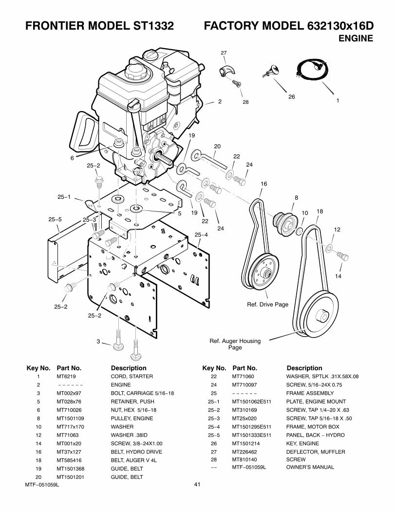
FRONTIER MODEL ST1332 FACTORY MODEL 632130x16D
41MTF−051059L
ENGINE
1
ÁÁ
ÁÁÁÁ
25−1
2
3
25−4
25−2
25−3
6
5
20
2224
18
8
10
12
16
Ref. Drive Page
Ref. Auger HousingPage
14
19
19
25−5
25−2
25−2
2224
26
27
28
Key No. Part No. Description Key No. Part No. Description1 MT6219 CORD, STARTER
2 − − − − − − ENGINE
3 MT002x97 BOLT, CARRIAGE 5/16−18
5 MT028x76 RETAINER, PUSH
6 MT710026 NUT, HEX 5/16−18
8 MT1501109 PULLEY, ENGINE
10 MT717x170 WASHER
12 MT71063 WASHER .38ID
14 MT001x20 SCREW, 3/8−24X1.00
16 MT37x127 BELT, HYDRO DRIVE
18 MT585416 BELT, AUGER V 4L
19 MT1501368 GUIDE, BELT
20 MT1501201 GUIDE, BELT
22 MT71060 WASHER, SPTLK .31X.58X.08
24 MT710097 SCREW, 5/16−24X 0.75
25 − − − − − − FRAME ASSEMBLY
25−1 MT1501062E511 PLATE, ENGINE MOUNT
25−2 MT310169 SCREW, TAP 1/4−20 X .63
25−3 MT25x020 SCREW, TAP 5/16−18 X .50
25−4 MT1501295E511 FRAME, MOTOR BOX
25−5 MT1501333E511 PANEL, BACK − HYDRO
26 MT1501214 KEY, ENGINE
27 MT226462 DEFLECTOR, MUFFLER
28 MT810140 SCREW
−− MTF−051059L OWNER’S MANUAL
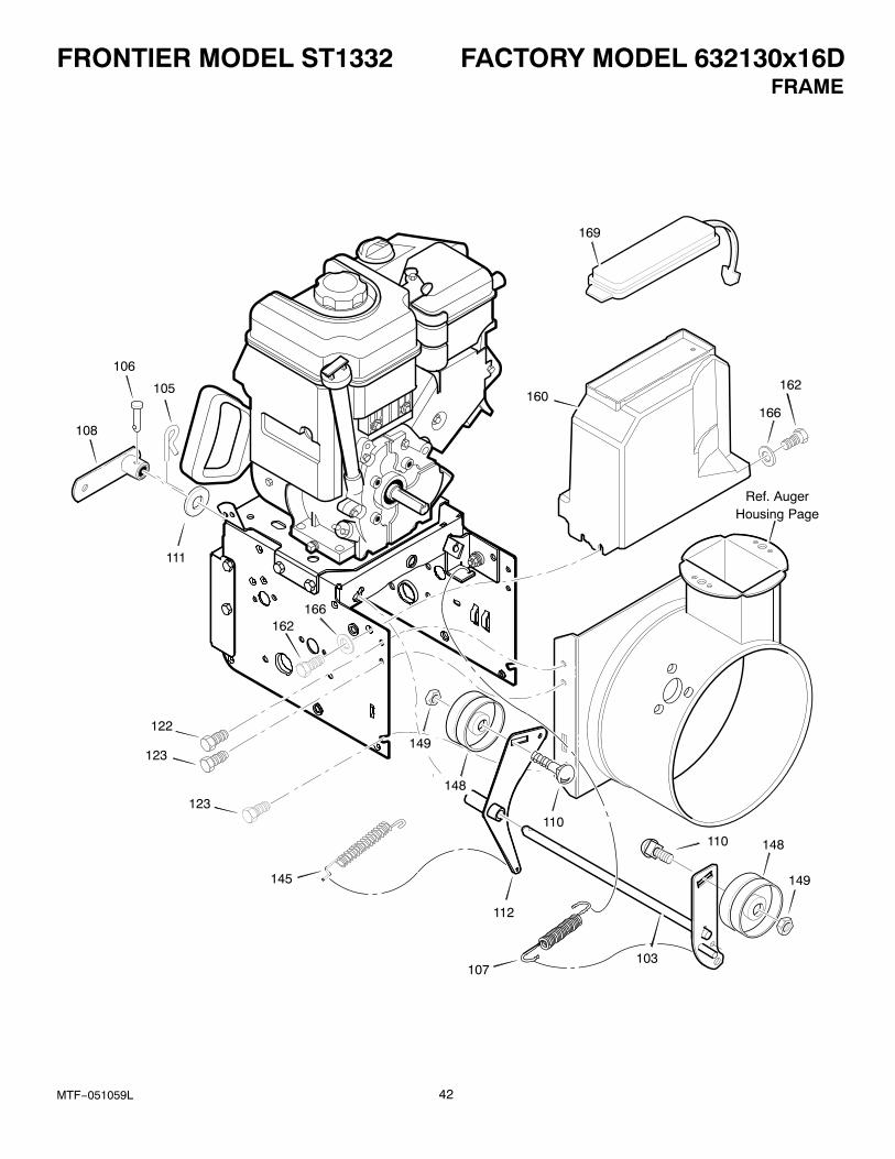
FRONTIER MODEL ST1332 FACTORY MODEL 632130x16D
42MTF−051059L
FRAME
106
108
105
111
122
123
123
145
162166
149
148
112
107103
148
149
110
110
166
162160
169
Ref. AugerHousing Page

FRONTIER MODEL ST1332 FACTORY MODEL 632130x16D
43MTF−051059L
FRAME
Key No. Part No. Description
103 MT1501369 YZ IDLER ASSEMBLY, AUGER
105 MT711682 PIN, HAIR .38DIAX1.64LG
106 MT761761 PIN, CLEVIS 3/16” DIA
107 MT165x159 SPRING, TENSION
108 MT761675 YZ ASSY., SPRING ATTACH
110 MT585781 BOLT, 3/8−16X1.25 CARR.
111 MT711617 WASHER, FLAT
112 MT1501370 YZ BRACKET, IDLER
122 MT25X020 SCREW, TAP 5/16−18 X .50
123 MT25X021 SCREW, TAP 5/16−18 X .75
145 MT165x155 SPRING, CLUTCH
148 MT1502120 PULLEY, IDLER
149 MT590 NUT, JAM 3/8−16
160 MT1502182 COVER, BELT
162 MT26x306 SCREW, TAP
167 MT71067 WASHER, FLAT
169 MT760539 LID, TOOL BOX
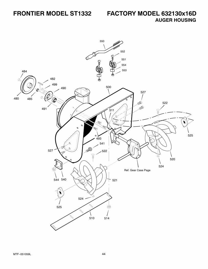
FRONTIER MODEL ST1332 FACTORY MODEL 632130x16D
44MTF−051059L
AUGER HOUSING
500
527
480 485
499
482
490
491
493
527
522
522
521
525
525
524
524
520
510 514
Ref. Gear Case Page
540
541
544
511
484
550
551
552
553
554

FRONTIER MODEL ST1332 FACTORY MODEL 632130x16D
45MTF−051059L
AUGER HOUSING
Key No. Part No. Description
480 MT583146 PULLEY, 4L 8.40 OD
482 MT2001022 KEY, SQUARE 3/16 X 3/4
484 MT15x112 NUT, 1/2−20
485 MT1501158 SPACER, FRICTION PULLEY
490 MT582957 YZ RETAINER, BALL BRNG
491 MT1501389 BEARING, BALL
493 MT001X92 BOLT, HEX 5/16−18X .50
499 MT710026 NUT, 5/16−18 HEXWDFLLK
500 MT1501721E511 HOUSING, ASSY
510 MT760666E701 BLADE, SCRAPER
511 MT001x45 BOLT, 5/16−18X.62
514 MT710026 NUT, 5/16−18
520 MT1501602E701 AUGER, ASSY, LH
521 MT1501595E701 AUGER, ASSY, RH
522 MT578647 SCREW, 5/16−18
524 MT71391 NUT, 5/16−18
525 MT53757 BEARING, FLANGE
527 MT25X021 SCREW, 5/16−18X .75
540 MT1502093E701 SKID, HEIGHT ADJUST
541 MT908156 BOLT, 5/16−18 X .50
544 MT710026 NUT, 5/16−18
550 MT1501576 BRUSH, CLEANOUT
551 MT1501672 CLIP, RETAINER
552 MT06x115 SCREW
553 MT15x146 NUT
554 MT578063 BLOCK
− − MT1501217 KIT, SHEAR BOLT
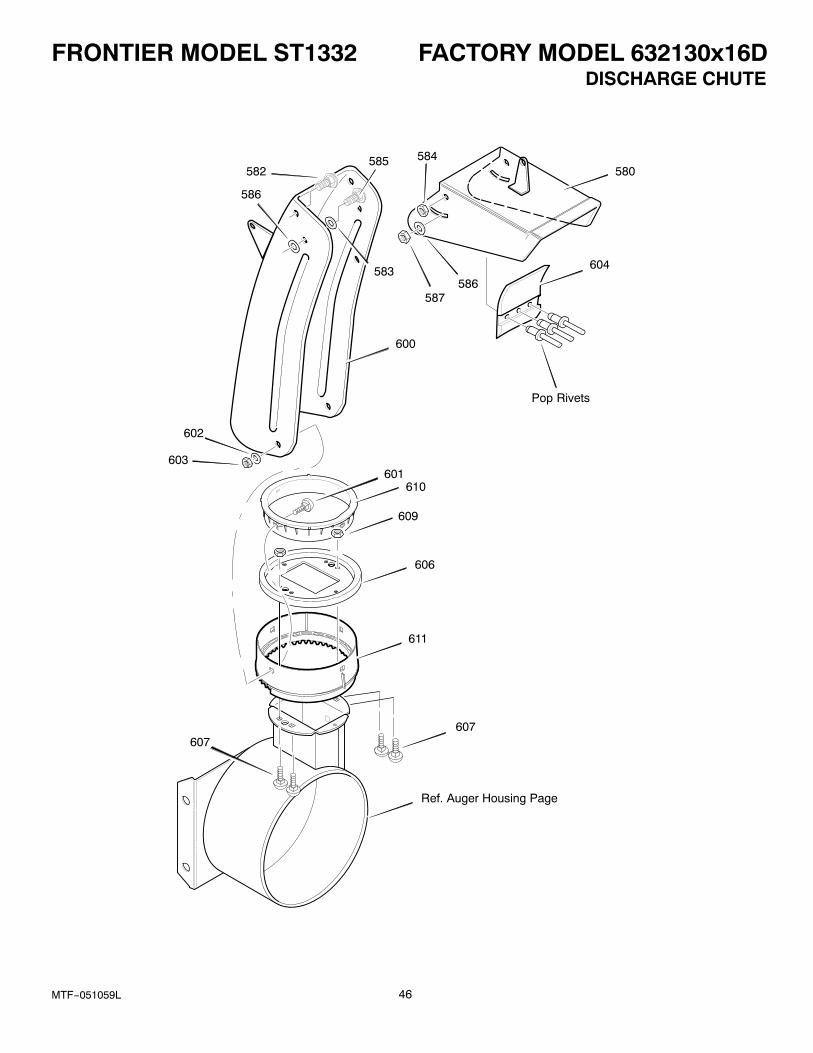
FRONTIER MODEL ST1332 FACTORY MODEL 632130x16D
46MTF−051059L
DISCHARGE CHUTE
580
586587
584582
586
600
602
603601
610
609
606
611
607
585
Ref. Auger Housing Page
607
604
Pop Rivets
583
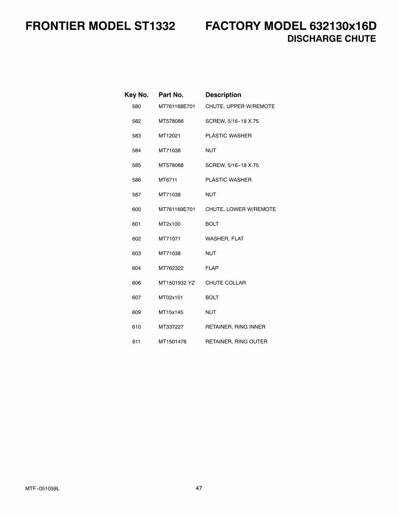
FRONTIER MODEL ST1332 FACTORY MODEL 632130x16D
47MTF−051059L
DISCHARGE CHUTE
Key No. Part No. Description
580 MT761168E701 CHUTE, UPPER W/REMOTE
582 MT578088 SCREW, 5/16−18 X.75
583 MT12021 PLASTIC WASHER
584 MT71038 NUT
585 MT578088 SCREW, 5/16−18 X.75
586 MT6711 PLASTIC WASHER
587 MT71038 NUT
600 MT761169E701 CHUTE, LOWER W/REMOTE
601 MT2x100 BOLT
602 MT71071 WASHER, FLAT
603 MT71038 NUT
604 MT762322 FLAP
606 MT1501932 YZ CHUTE COLLAR
607 MT02x101 BOLT
609 MT15x145 NUT
610 MT337227 RETAINER, RING INNER
611 MT1501476 RETAINER, RING OUTER
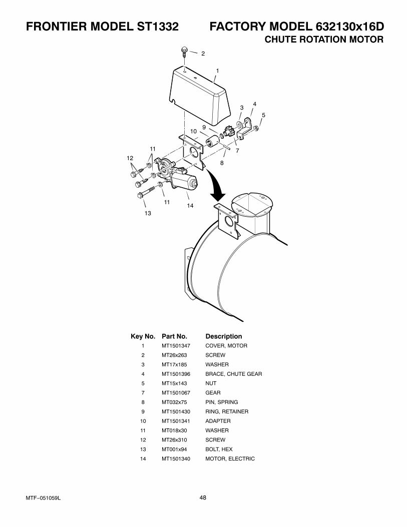
FRONTIER MODEL ST1332 FACTORY MODEL 632130x16D
48MTF−051059L
CHUTE ROTATION MOTOR
1
2
34
5
7
8
910
11
12
13
11 14
Key No. Part No. Description1 MT1501347 COVER, MOTOR
2 MT26x263 SCREW
3 MT17x185 WASHER
4 MT1501396 BRACE, CHUTE GEAR
5 MT15x143 NUT
7 MT1501067 GEAR
8 MT032x75 PIN, SPRING
9 MT1501430 RING, RETAINER
10 MT1501341 ADAPTER
11 MT018x30 WASHER
12 MT26x310 SCREW
13 MT001x94 BOLT, HEX
14 MT1501340 MOTOR, ELECTRIC
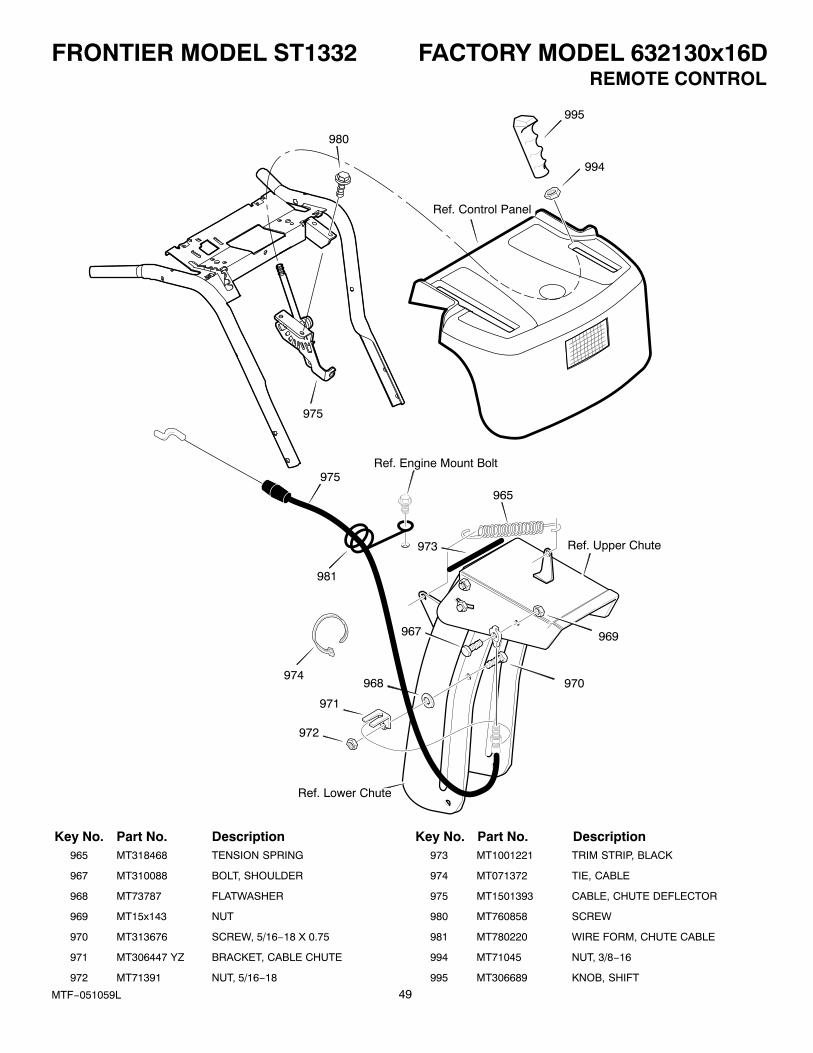
FRONTIER MODEL ST1332 FACTORY MODEL 632130x16D
49MTF−051059L
REMOTE CONTROL
975Ref. Engine Mount Bolt
981
974
965
Ref. Upper Chute
972
971
Ref. Lower Chute
968 970
969967
973
995
994
Ref. Control Panel
975
980
Key No. Part No. Description Key No. Part No. Description965 MT318468 TENSION SPRING
967 MT310088 BOLT, SHOULDER
968 MT73787 FLATWASHER
969 MT15x143 NUT
970 MT313676 SCREW, 5/16−18 X 0.75
971 MT306447 YZ BRACKET, CABLE CHUTE
972 MT71391 NUT, 5/16−18
973 MT1001221 TRIM STRIP, BLACK
974 MT071372 TIE, CABLE
975 MT1501393 CABLE, CHUTE DEFLECTOR
980 MT760858 SCREW
981 MT780220 WIRE FORM, CHUTE CABLE
994 MT71045 NUT, 3/8−16
995 MT306689 KNOB, SHIFT
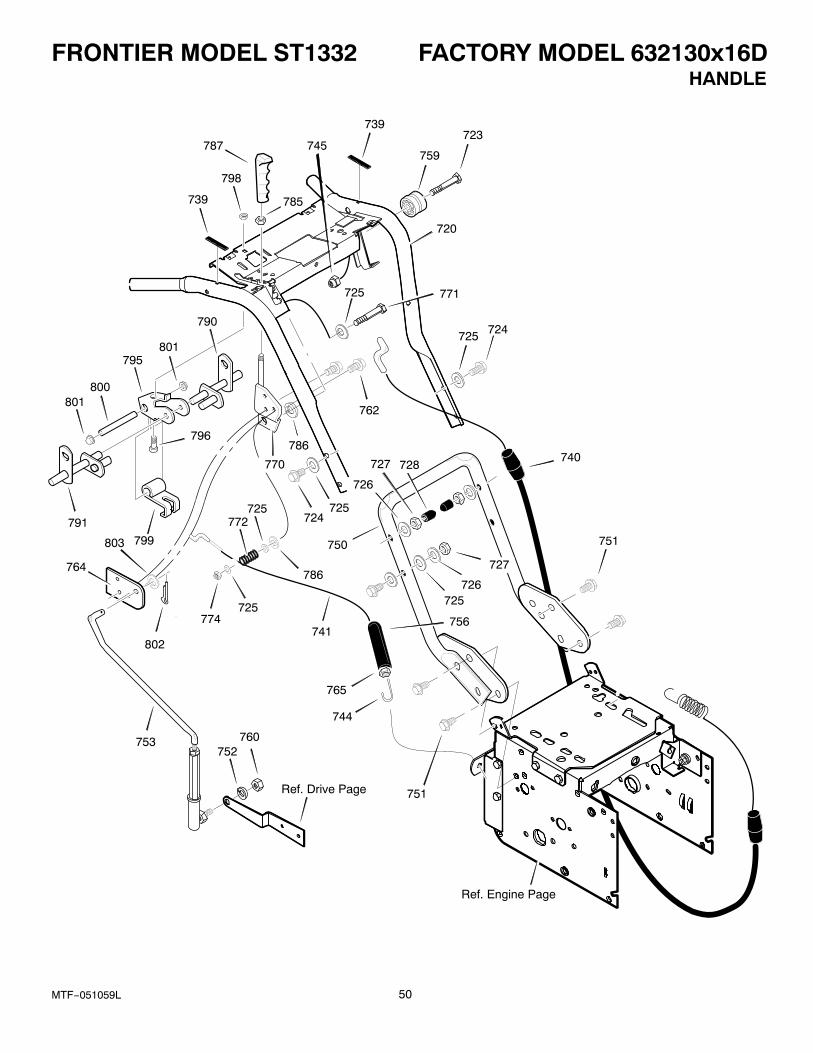
FRONTIER MODEL ST1332 FACTORY MODEL 632130x16D
50MTF−051059L
HANDLE
774725
785
798
787
739
771
720
790
801795
800801
791
796
799
741
724
740
725 724
728727
726
751
759
756
751
727
726725
739
725772
723
744
802
764
803
753752
760
Ref. Drive Page
762
745
786
765
725
725
Ref. Engine Page
750
770
786

FRONTIER MODEL ST1332 FACTORY MODEL 632130x16D
51MTF−051059L
HANDLE
Key No. Part No. Description720 MT1501381E701 ASSY., HANDLE
723 MT01x129 BOLT
724 MT7288 SCREW
725 MT71072 WASHER
726 MT71062 WASHER
727 MT71044 NUT
728 MT7289 STOP, PLASTIC
739 MT4049 BUMPER
740 MT1501363 CABLE, DRIVE
741 MT1501451 CABLE, AUGER
744 MT1673 SPRING, AUGER CLUTCH
745 MT15x116 NUT, HEX − 1/4−20
750 MT1501449E701 HANDLE, LOWER
751 MT25x021 SCREW
752 MT71060 WASHER
753 MT1501465 ASSEMBLY, ROD
756 MT308146 BOOT, SPRING
759 MT579860 SPOOL, CABLE
760 MT71042 NUT, 5/16−24
762 MT310169 SCREW 1/4−20X0.63
764 MT1501367 YZ BRACKET, CONTROL
765 MT15x145 NUT, HEX − 1/4−20
770 MT1501375 YZ BRACKET, SHIFT
771 MT1x157 YZ SCREW
772 MT164x39 SPRING
774 MT71046 NUT, HEX, 3/8−16
785 MT71045 NUT, HEX, 3/8−16
786 MT17x217 WASHER
787 MT306689 GRIP, LEVER
790 MT578926E701 ROD, ASSY LH
791 MT578924E701 ROD, ASSY RH
795 MT579002 BRACKET, CAM
796 MT002x53 SCREW
798 MT71038 NUT, NYLOCK
799 MT8417 CAM LOCK
800 MT584673 PIN, SPRING PIVOT
801 MT73664 NUT, PUSH ON
802 MT71081 PIN, COTTER
803 MT71071 WASHER
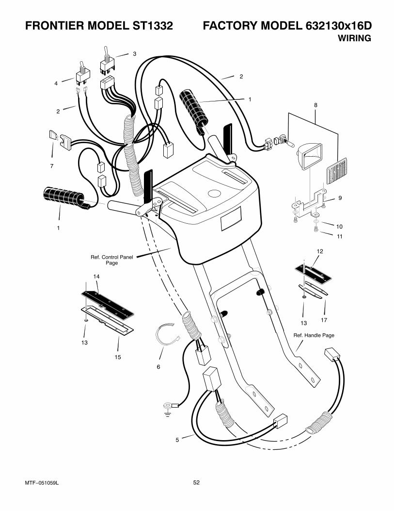
FRONTIER MODEL ST1332 FACTORY MODEL 632130x16D
52MTF−051059L
WIRING
Ref. Control PanelPage
Ref. Handle Page
8
9
10
11
6
2
2
1
3
4
5
7
1
13
13
15
14
12
17

FRONTIER MODEL ST1332 FACTORY MODEL 632130x16D
53MTF−051059L
WIRING
Key No. Part No. Description
1 MT1501352 GRIP, HEATED
2 MT1501351 WIRE HARNESS, UPPER
3 MT1501348 SWITCH, CHUTE ROTATION
4 MT1501349 SWITCH, HEATED GRIP
5 MT1501350 WIRE HARNESS, LOWER
6 MT071372 TIE, CABLE
7 − − − − − FUSE, 7.5 AMP AUTOMOTIVE
8 MT762343 HEADLIGHT ASSEMBLY *
9 MT1501412 BRACKET
10 MT901736 WASHER, FLAT
11 MT901696 SCREW #8 X .50
12 MT1501543 COVER, CHUTE LEVER
13 MT028x79 NUT, PUSH
14 MT1501542 COVER, SPEED LEVER
15 MT1501544 FRAME, SPEED LEVER
17 MT1501545 FRAME, CHUTE LEVER
* For replacement bulb, use Standard GE or Phillips #894.
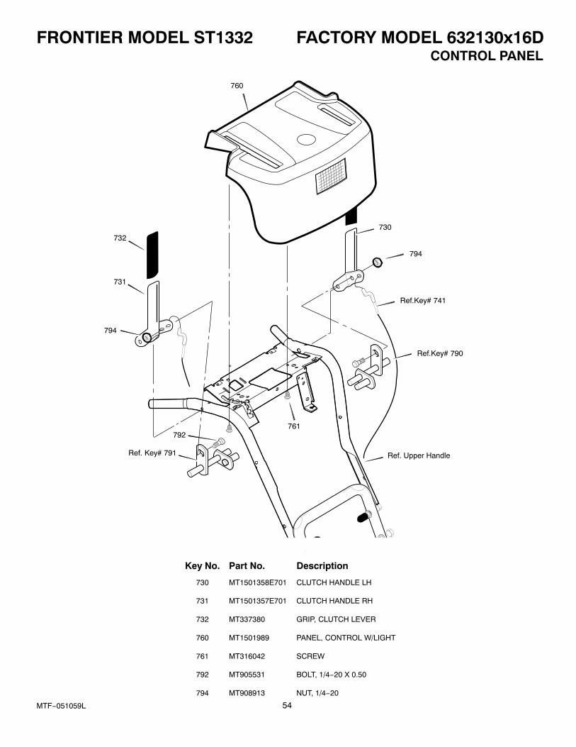
FRONTIER MODEL ST1332 FACTORY MODEL 632130x16D
54MTF−051059L
CONTROL PANEL
760
730
Ref.Key# 741
794
731
761792
Ref. Key# 791 Ref. Upper Handle
Ref.Key# 790
794
732
Key No. Part No. Description
730 MT1501358E701 CLUTCH HANDLE LH
731 MT1501357E701 CLUTCH HANDLE RH
732 MT337380 GRIP, CLUTCH LEVER
760 MT1501989 PANEL, CONTROL W/LIGHT
761 MT316042 SCREW
792 MT905531 BOLT, 1/4−20 X 0.50
794 MT908913 NUT, 1/4−20
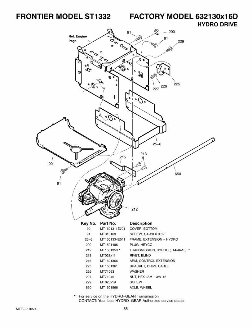
FRONTIER MODEL ST1332 FACTORY MODEL 632130x16D
55MTF−051059L
HYDRO DRIVE
Ref. EnginePage
91
91229
225226
227
25−6
213215
650
212
91
90
200
Key No. Part No. Description90 MT1501311E701 COVER, BOTTOM
91 MT310169 SCREW, 1/4−20 X 0.62
25−6 MT1501334E511 FRAME, EXTENSION − HYDRO
200 MT1501496 PLUG, HEYCO
212 MT1501353 * TRANSMISSION, HYDRO (314−0410) *
213 MT021x11 RIVET, BLIND
215 MT1501366 ARM, CONTROL EXTENSION
225 MT1501361 BRACKET, DRIVE CABLE
226 MT71063 WASHER
227 MT71045 NUT, HEX JAM − 3/8−16
229 MT025x19 SCREW
650 MT1501566 AXLE, WHEEL
* For service on the HYDRO−GEAR TransmissionCONTACT: Your local HYDRO−GEAR Authorized service dealer.
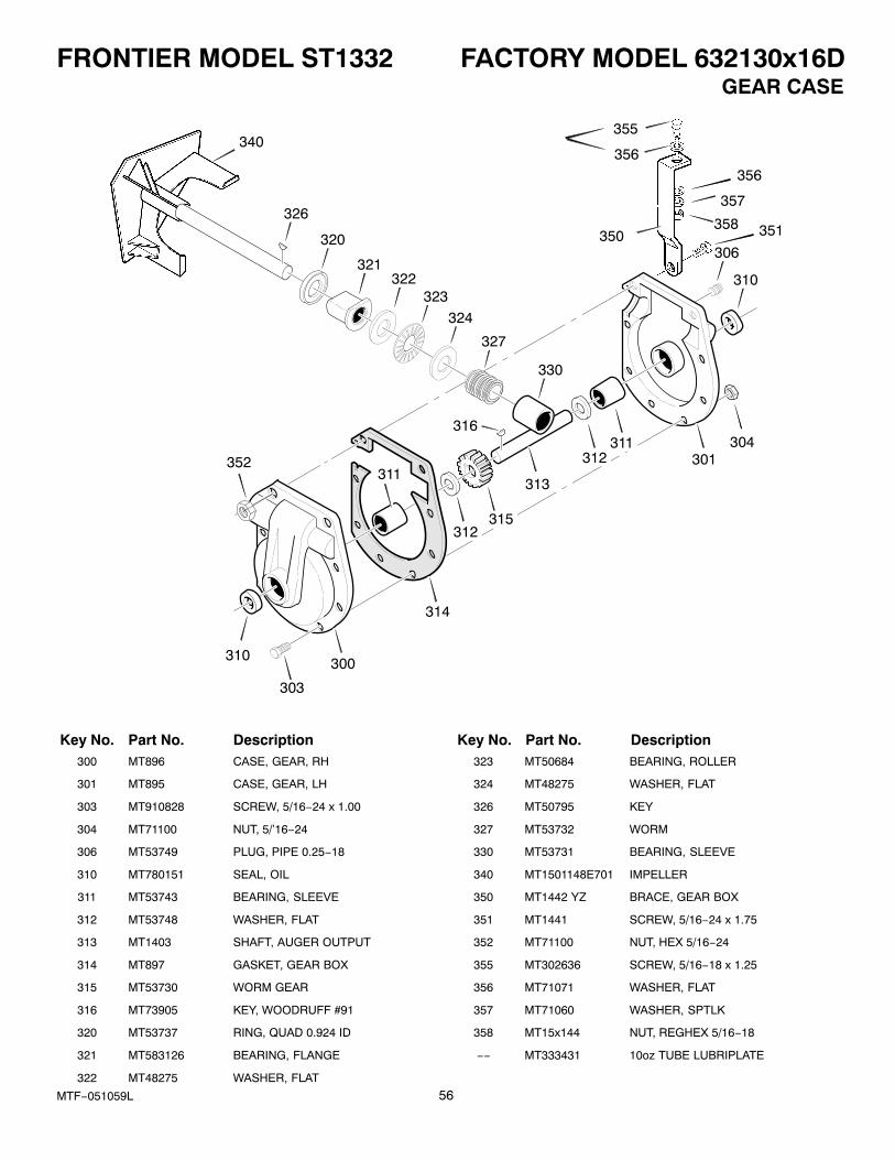
FRONTIER MODEL ST1332 FACTORY MODEL 632130x16D
56MTF−051059L
GEAR CASE
326
320
321322
323
324
327
330
311312
306
310
304301
303
310 300
314
311
312315
313
316
340
351
355
356
350
356
357
358
352
Key No. Part No. Description Key No. Part No. Description300 MT896 CASE, GEAR, RH
301 MT895 CASE, GEAR, LH
303 MT910828 SCREW, 5/16−24 x 1.00
304 MT71100 NUT, 5/’16−24
306 MT53749 PLUG, PIPE 0.25−18
310 MT780151 SEAL, OIL
311 MT53743 BEARING, SLEEVE
312 MT53748 WASHER, FLAT
313 MT1403 SHAFT, AUGER OUTPUT
314 MT897 GASKET, GEAR BOX
315 MT53730 WORM GEAR
316 MT73905 KEY, WOODRUFF #91
320 MT53737 RING, QUAD 0.924 ID
321 MT583126 BEARING, FLANGE
322 MT48275 WASHER, FLAT
323 MT50684 BEARING, ROLLER
324 MT48275 WASHER, FLAT
326 MT50795 KEY
327 MT53732 WORM
330 MT53731 BEARING, SLEEVE
340 MT1501148E701 IMPELLER
350 MT1442 YZ BRACE, GEAR BOX
351 MT1441 SCREW, 5/16−24 x 1.75
352 MT71100 NUT, HEX 5/16−24
355 MT302636 SCREW, 5/16−18 x 1.25
356 MT71071 WASHER, FLAT
357 MT71060 WASHER, SPTLK
358 MT15x144 NUT, REGHEX 5/16−18
−− MT333431 10oz TUBE LUBRIPLATE
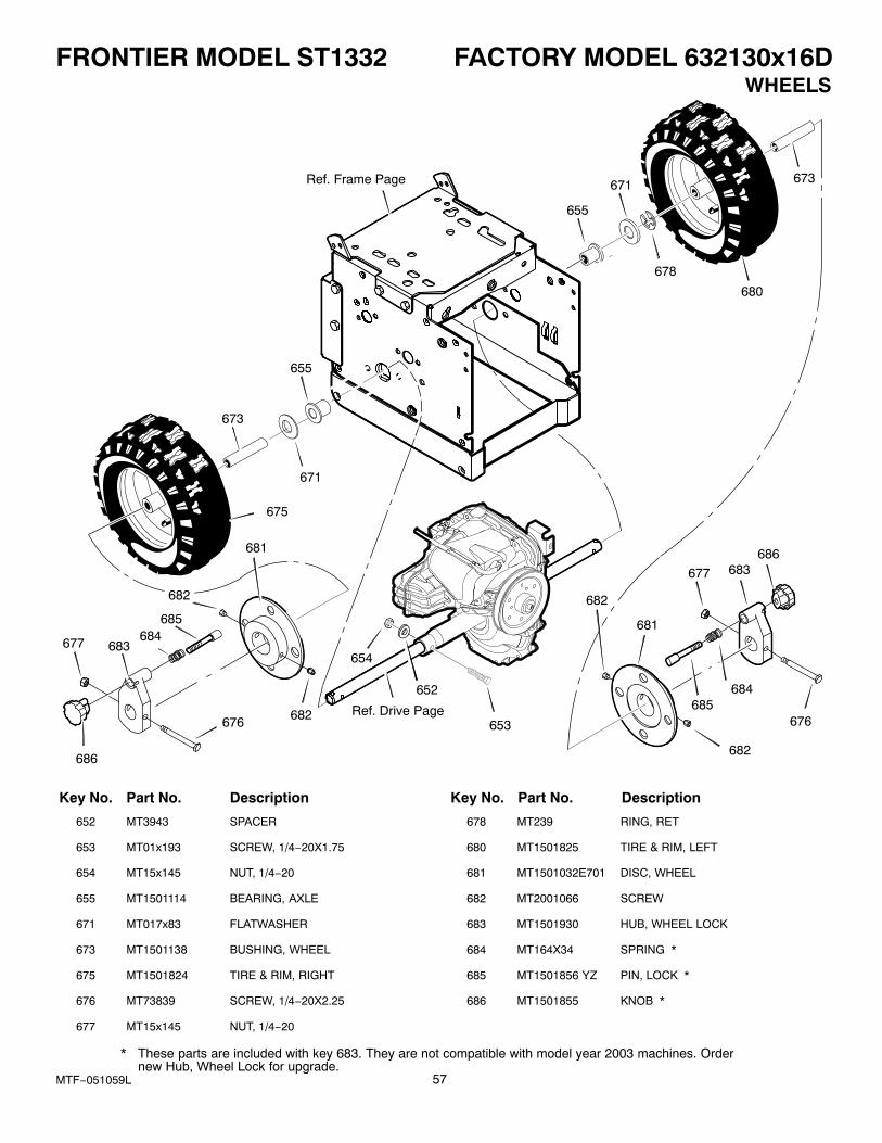
FRONTIER MODEL ST1332 FACTORY MODEL 632130x16D
57MTF−051059L
WHEELS
Ref. Frame Page 673
680
678
671
655
655
671
673
675
677 683684
685
682
681
676 682
686
654
653
682
681
677
685684
682
683686
652
676Ref. Drive Page
Key No. Part No. Description Key No. Part No. Description
652 MT3943 SPACER
653 MT01x193 SCREW, 1/4−20X1.75
654 MT15x145 NUT, 1/4−20
655 MT1501114 BEARING, AXLE
671 MT017x83 FLATWASHER
673 MT1501138 BUSHING, WHEEL
675 MT1501824 TIRE & RIM, RIGHT
676 MT73839 SCREW, 1/4−20X2.25
677 MT15x145 NUT, 1/4−20
678 MT239 RING, RET
680 MT1501825 TIRE & RIM, LEFT
681 MT1501032E701 DISC, WHEEL
682 MT2001066 SCREW
683 MT1501930 HUB, WHEEL LOCK
684 MT164X34 SPRING *
685 MT1501856 YZ PIN, LOCK *
686 MT1501855 KNOB *
* These parts are included with key 683. They are not compatible with model year 2003 machines. Ordernew Hub, Wheel Lock for upgrade.
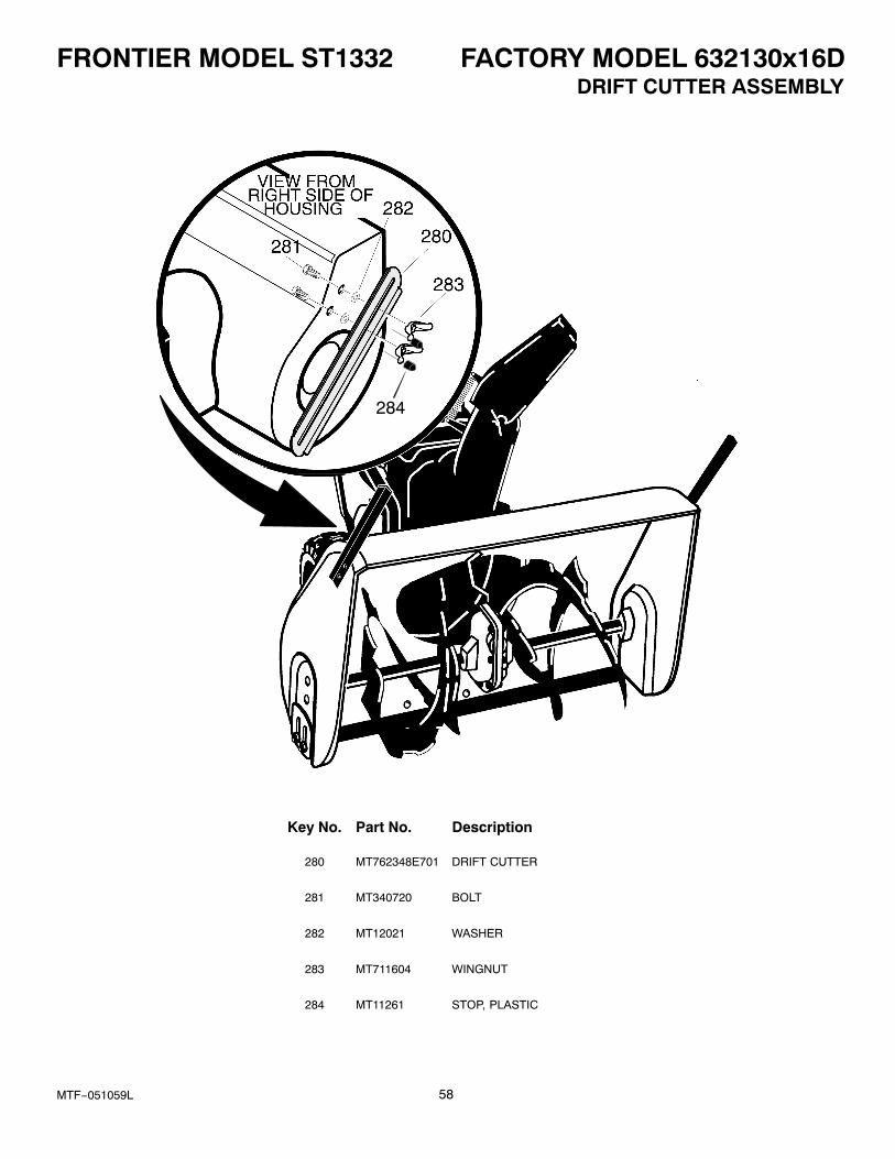
FRONTIER MODEL ST1332 FACTORY MODEL 632130x16D
58MTF−051059L
DRIFT CUTTER ASSEMBLY
284
Key No. Part No. Description
280 MT762348E701 DRIFT CUTTER
281 MT340720 BOLT
282 MT12021 WASHER
283 MT711604 WINGNUT
284 MT11261 STOP, PLASTIC
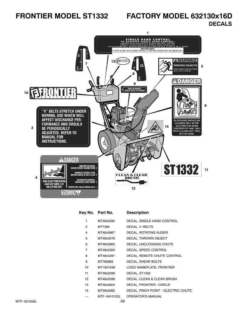
FRONTIER MODEL ST1332 FACTORY MODEL 632130x16D
59MTF−051059L
DECALS1
2
4
7
8
9
11
5
12
14
13
10
6
Key No. Part No. Description
1 MT48x5294 DECAL, SINGLE HAND CONTROL
2 MT7390 DECAL, V−BELTS
4 MT48x5967 DECAL, ROTATING AUGER
5 MT48x5578 DECAL, THROWN OBJECT
6 MT48x5965 DECAL, UNCLOGGING CHUTE
7 MT48x5300 DECAL, SPEED CONTROL
8 MT48x5297 DECAL, REMOTE CHUTE CONTROL
9 MT760983 DECAL, SHEAR BOLTS
10 MT1501548 LOGO NAMEPLATE, FRONTIER
11 MT48x5299 DECAL, ST1332
12 MT48x5599 DECAL, CLEAN & CLEAR BRUSH
13 MT48x5604 DECAL, FRONTIER −CIRCLE
14 MT48x5582 DECAL, PINCH POINT − ELECTRIC CHUTE
−− MTF−0410122L OPERATOR’S MANUAL

SPECIFICATIONS ST1332
60MTF−051059L
Engine Briggs & Stratton Intek Snow OHV
Horsepower 13 hp
Starter Electric / Recoil
Fuel Capacity 4 quarts
Drive System Hydrostatic
Speeds Variable Fwd/Rev
Tire Diameter 16”
Traction Control Wheel Lock
Clearing Width 32”
Housing Height 23.5”
Auger Diameter 16”
Auger Type Steel / Saw Tooth
Impeller Diameter 12”
Chute Rotation Electric
Chute Turning Radius 190�
Deflector Control Remote
Weight 307 lbs
Warranty − Engine 3 years
Warranty − Machine 3 years