Embed Size (px)
Citation preview

POWER SYSTEMS DIVISION GRID SYSTEMS CONSULTING
STABILITY ANALYSIS FOR FACILITY STUDY OF PID-226
FINAL REPORT REPORT NO.: 2009-E3350-R1 Issued On: August 19, 2009 Revised on: August 27, 2009 Revised on: February 19, 2010 Prepared for: Southwest Power Pool, Inc. ABB Inc. Power Systems Division Grid Systems Consulting 940 Main Campus Drive, Suite 300 Raleigh, NC 27606

ii
Legal Notice This document, prepared by ABB Inc., is an account of work sponsored by Southwest Power Pool, Inc. (SPP). Neither SPP nor ABB Inc, nor any person or persons acting on behalf of either party: (i) makes any warranty or representation, expressed or implied, with respect to the use of any information contained in this report, or that the use of any information, apparatus, method, or process disclosed in this report may not infringe privately owned rights, or (ii) assumes any liabilities with respect to the use of or for damages resulting from the use of any information, apparatus, method, or process disclosed in this document.

ABB Inc – Grid Systems Consulting Technical Report
Southwest Power Pool, Inc. No. 2009-E3350-R1
Facility Study for PID-226
Date: 8/21/2009
# Pages
45
Author(s): Reviewed by: Approved by: Trinadh Dwibhashyam Amit Kekare Willie Wong Executive Summary Southwest Power Pool, Inc (SPP) at the request of Entergy Services Inc. has commissioned ABB Inc. to perform a stability analysis for Facility study of PID-226, which is a request for 206 MW uprate of existing G. Gulf Unit #1 in the Entergy transmission system. A system impact study for the PID-226 has previously been completed. The objective of this study was to supplement the stability analysis performed in the system impact study for PID-226 Project. To that end, selected faults at G. Gulf 500 kV substation were simulated and a Critical Clearing Time Analysis was performed at G. Gulf 500 kV substation. The study was performed on 2012 Summer Peak case, provided by SPP/Entergy. The system was stable following all simulated normally cleared and stuck-breaker faults. No voltage criteria violation was observed following simulated faults. The Critical Clearing times at G. Gulf 500 kV substations are within the capabilities of the existing protection systems. The smallest CCT at G. Gulf 500 kV substation was 5 + 15 cycles for a fault involving loss of G. Gulf – B. Wilson 500 kV. Based on the results of stability analysis it can be concluded that proposed PID-226 project does not adversely impact the stability of the Entergy System in the local area. Also, PID-226 does not adversely impact the Critical Clearing time at G. Gulf 500 kV substations. Hence, no transmission reinforcements and/ or upgrades were identified for the interconnection of the PID-226 project.
iii

iv
The results of this analysis are based on available data and assumptions made at the time of conducting this study. If any of the data and/or assumptions made in developing the study model change, the results provided in this report may not apply.
Rev No.
Revision Description Date Authored by Reviewed by Approved by
0 Draft Report 8/21/09 Trinadh A. Kekare W. Wong
1 Updated per Entergy comments 8/27/09 Trinadh A. Kekare W. Wong
2
Updated for Ray Braswell 500 kV fault results 02/19/10 Trinadh A. Kekare W. Wong
DISTRIBUTION: Daniel Epperson – Southwest Power Pool, Inc. Brad Finkbeiner – Southwest Power Pool, Inc. Mukund Chander – Entergy Services Inc.

v
TABLE OF CONTENTS 1 INTRODUCTION ...............................................................................6 2 STABILITY ANALYSIS ......................................................................7
2.1 STABILITY ANALYSIS METHODOLOGY ..................................................7 2.2 STUDY MODEL DEVELOPMENT ............................................................9 2.3 TRANSIENT STABILITY ANALYSIS .......................................................12 2.4 CRITICAL CLEARING TIME ANALYSIS..................................................24
3 CONCLUSIONS ..............................................................................27 APPENDIX A DATA PROVIDED BY CUSTOMER ........................................................28 APPENDIX B LOAD FLOW AND STABILITY DATA IN PSSE FORMAT ...........................43 APPENDIX C PLOTS FOR STABILITY SIMULATIONS ..................................................45

1 INTRODUCTION Southwest Power Pool, Inc. (SPP) at the request of Entergy Services Inc. has commissioned ABB Inc. to perform a stability analysis for Facility Study of PID-226, which is a request for 206 MW uprate of the existing G. Gulf Unit in the Entergy transmission system. A system impact study1 for the PID-226 has previously been completed. The objective of this study was to supplement the stability analysis performed in the system impact study for PID-226 Project. The study was performed on 2012 Summer Peak case, provided by Entergy. Figure 1-1 shows the location of the G. Gulf Unit with proposed 206 MW increase of generation.
Proposed PID-226
Figure 1-1 PID 226 Project location
1 “Stability Analysis for PID-226 System Impact study”, March 30, 2009
6
ABB

2 STABILITY ANALYSIS 2.1 STABILITY ANALYSIS METHODOLOGY Using Planning Standards approved by NERC, the following stability definition was applied in the Transient Stability Analysis: “Power system stability is defined as that condition in which the differences of the angular positions of synchronous machine rotors become constant following an aperiodic system disturbance.” Stability analysis was performed using Siemens-PTI’s PSS/ETM dynamics program V30.3.2. Three-phase and single-phase line faults were simulated for the specified duration and synchronous machine rotor angles and wind turbine generator speeds were monitored to check whether synchronism is maintained following fault removal. Based on the Entergy study criteria, three-phase faults with normal clearing and delayed clearing were simulated. Stability analysis was performed using the PSS/E dynamics program, which only simulates the positive sequence network. Unbalanced faults involve the positive, negative, and zero sequence networks. For unbalanced faults, the equivalent fault admittance must be inserted in the PSS/E positive sequence model between the faulted bus and ground to simulate the effect of the negative and zero sequence networks. For a single-line-to-ground (SLG) fault, the fault admittance equals the inverse of the sum of the positive, negative and zero sequence Thevenin impedances at the faulted bus. Since PSS/E inherently models the positive sequence fault impedance, the sum of the negative and zero sequence Thevenin impedances needs to be added and entered as the fault impedance at the faulted bus. For three-phase faults, a fault admittance of –j2E9 is used (essentially infinite admittance or zero impedance). For the single phase stuck breaker faults, the fault admittances considered are mentioned in Table 2-4. Transient Voltage Criteria In addition to criteria for the stability of the machines, Entergy has evaluation criteria for the transient voltage dip as follows: • 3-phase fault or single-line-ground fault with normal clearing resulting in the loss of
a single component (generator, transmission circuit or transformer) or a loss of a single component without fault: Not to exceed 20% for more than 20 cycles at any bus Not to exceed 25% at any load bus Not to exceed 30% at any non-load bus
• 3-phase faults with normal clearing resulting in the loss of two or more components (generator, transmission circuit or transformer), and SLG fault with delayed clearing resulting in the loss of one or more components:
7
ABB

Not to exceed 20% for more than 40 cycles at any bus Not to exceed 30% at any bus
The duration of the transient voltage dip excludes the duration of the fault. The transient voltage dip criteria will not be applied to three-phase faults followed by stuck breaker conditions unless the determined impact is extremely widespread. The voltages at all local buses (above 115 kV) were monitored during each of the fault cases as appropriate. As there is no specific voltage dip criteria for three-phase stuck breaker faults, the results of these faults were compared with the most stringent voltage dip criteria of - not to exceed 20 % for more than 20 cycles. Critical Clearing Time (CCT) Analysis An evaluation of the critical clearing times was carried out for faults on lines and transformers in the G. Gulf 500 kV substation Critical Clearing Time assessment was performed on 2012 summer peak system conditions. Critical Clearing Time (CCT) was calculated for a three-phase stuck-breaker fault on each branch connected to G. Gulf 500 kV substation. CCT is defined as the longest fault clearing time for which stability is maintained. Independent pole operation (IPO) was assumed for breakers in both switchyards, with breaker failure occurring on only a single phase. This results in a three-phase fault becoming a single-phase fault at the normal clearing time. The single phase fault is then cleared by backup protection. The Normal Clearing Time was kept equal to the normal value (5 cycles on 500 kV and 6 cycles on 230 kV) and the backup clearing time was varied to find the CCT. All machines in the Entergy system were monitored for stability.
8
ABB

9
ABB
2.2 STUDY MODEL DEVELOPMENT The study model consists of power flow cases and dynamics databases, developed as follows. Power Flow Case A Powerflow case “EN12S08_Final_U2_With Upgrades_unconv.sav” representing the 2012 Summer Peak conditions was provided by SPP/ Entergy. Two prior-queued projects, PID-223 and PID-224, were added to the base case. Thus a pre-project powerflow case was established and named as ‘PRE-PID-226.sav’. The proposed PID-226 project is a 206 MW uprate at G. Gulf Unit. The additional 206 MW was dispatched against the White Bluff Unit #1. Table 2-1 summarizes the dispatch. Thus a post-project power flow case with PID-226 was established and named as ‘POST-PID-226.sav’.
Table 2-1 PID-226 project details System condition MW Point of Interconnection Sink
2012 Summer Peak 206 G. Gulf (#336821) White Bluff Unit 1 (#337652)
Figure 2-1 shows the PSS/E one-line diagram for the local area WITH the PID-226 project, for 2012 Summer Peak system conditions. Stability Database A base case stability database was provided by SPP/Entergy in a PSSE *.dyr file format (‘red11S_newnum.dyr’). To create a dynamic database (a snapshot file) for PRE-PID-226 powerflow case, stability data for PID-223 and PID-224 and the dynamic data in ‘dystop.dyr’ was appended to the base case stability database. After the proposed uprate of the G. Gulf unit the total MW output of the plant will be 1544 MW, higher than the existing maximum limit (0.90 p.u. on 1600 MVA) on the Governor. For the stability analysis purpose, to avoid the initial condition errors, the limit was changed from 0.90 p.u to 0.97 p.u. on 1600 MVA base. Given the large system under consideration impact of such assumption will not be significant. The pre-project stability database was updated to create dynamic database for Post-PID-226 powerflow case. The data provided at the Interconnection Request for PID-226 is included in Appendix A. The PSS/E power flow and stability data for PID-226, used for this study, are included in Appendix B.

Figure 2-1 One-line Diagram of the local area without PID-226 (2012 Summer Peak)
10
ABB

ABB
11
Figure 2-2 One-line Diagram of the local area with PID-226 (2012 Summer Peak)

2.3 TRANSIENT STABILITY ANALYSIS Stability simulations were run to examine the transient behavior of the G. Gulf Unit and impact of the proposed uprate on the Entergy system. Stability analysis was performed using the following procedure. First, three-phase faults with normal clearing were simulated. Next, the three-phase stuck breaker (IPO: 3PH-1PH) faults were simulated. The fault clearing times used for the simulations are given inTable 2-2.
Table 2-2: Fault Clearing Times Contingency at kV level Normal Clearing Delayed Clearing
500 5 cycles 5+9 cycles The breaker failure scenario was simulated with the following sequence of events: 1) At the normal clearing time for the primary breakers, the faulted line is tripped at the far end from the fault by normal breaker opening. 2) The fault remains in place for Three-phase stuck-breaker (IPO: 3PH-1PH) faults. The fault admittances is changed to Thevenin equivalent admittance of single phase faults. 3) The fault is then cleared by back-up clearing. If the system was found to be unstable, then the fault was repeated without the proposed PID-226 project. All line trips are assumed to be permanent (i.e. no high speed re-closure). Table 2-3 and Table 2-4 list all the fault cases that were simulated in this study. Fifteen (15) three phase normally cleared and twenty seven (27) three-phase stuck breaker converted into single-line-to-ground fault (following Independent Pole Operation of breakers) were simulated. For all cases analyzed, the initial disturbance was applied at t = 0.1 seconds. The breaker clearing was applied at the appropriate time following this fault inception.
12
ABB

Table 2-3 List of 3 Phase faults simulated for stability analysis
CASE LOCATION TYPE CLEARING
TIME (cycles)
BREAKER TRIP # TRIPPED FACILITIES
FAULT-1 G. Gulf - B. Wilson 500 kV 3 PH 5 J5224, J5216, J2240, J2244 G. Gulf - B. Wilson 500 kV FAULT-2 G. Gulf - Franklin 500 kV 3 PH 5 J2425, J2420, J5248, J5240 G. Gulf - Franklin 500 kV FAULT-3 B. Wilson - Perryville 500 kV 3 PH 5 R7372,R9872, J2233, J2218 B. Wilson - Perryville 500 kV FAULT-4 B. Wilson - Ray Braswell 500 kV 3 PH 5 J4928, J4920, J2230, J2233 B. Wilson - Ray Braswell 500 kV FAULT-5 B. Wilson 500/115 kV transformer #1 3 PH 5 J2214, J2222, B. Wilson 500/115 kV transformer #1 FAULT-6 Ray Braswell - Franklin 500 kV 3 PH 5 J2404, J2408, J4908, J4904 Ray Braswell - Franklin 500 kV FAULT-7 Ray Braswell - Lakeover 500 kV 3 PH 5 J4928,J4908, J9218, J9234 Ray Braswell - Lakeover 500 kV FAULT-8 Ray Braswell - B. Wilson 500 kV 3 PH 5 J4928, J4920, J2230, J2233 Ray Braswell - B. Wilson 500 kV FAULT-9 Ray Braswell 500/ 115 kV Transformer #1 3 PH 5 J4904, J4917 Ray Braswell 500/ 115 kV Transformer #1 FAULT-10 Ray Braswell 500/ 230 kV Transformer #1 3 PH 5 J4917, J4920 Ray Braswell 500/ 230 kV Transformer #1 FAULT-11 Franklin - McKinight 500 kV 3 PH 5 BRK#21105, BRK#21110, J2416,2412 Franklin - McKinight 500 kV FAULT-12 Franklin - Bogal USA - Adams Creek 500 kV 3 PH 5 S4402, S4405, J2416, J2420 Franklin - Bogal USA - Adams Creek 500 kV FAULT-13 Franklin - Ray Braswell 500 kV 3 PH 5 J2404, J2408, J4908, J4904 Franklin - Ray Braswell 500 kV FAULT-14 Franklin - G. Gulf 500 kv 3 PH 5 J2425, J2420, J5248, J5240 Franklin - G. Gulf 500 kv FAULT-15 Franklin 500/115 kV transformer #1 3 PH 5 J2425, J2404 Franklin 500/115 kV transformer #1
13
ABB

Table 2-4 List of 3 PhaseStuck Brekaer (IPO: 3PH-1PH) faults simulated for stability analysis CLEARING TIME
(cycles) CASE LOCATION TYPE PRIMARY Back-
up
SLG FAULT IMPEDANCE
(MVA)
STUCK BREAKER
#
PRIMARY BREAKER
TRIP #
SECONDARY BREAKER
TRIP TRIPPED FACILITIES
FAULT-1a G. Gulf - B. Wilson 500 kV 3 PH/SLG 5 9
640.02-j8505.34 J5224
J5216, J2240, J2244
J5208, J5236, J5248 G. Gulf - B. Wilson 500 kV
FAULT-2b G. Gulf - Franklin 500 kV 3 PH/SLG 5 9
640.02-j8505.34 J5248
J2425, J2420, J5240
J5208, J5236, J5224 G. Gulf - Franklin 500 kV
FAULT-3a B. Wilson - Perryville 500 kV 3 PH/SLG 5 9
779.96-j8641.41 J2233
R7372,R9872, J2218
J2230, J4928, J4920
B. Wilson - Perryville 500 kV; B. wilson Ray Braswell 500 kV
FAULT-3b B. Wilson - Perryville 500 kV 3 PH/SLG 5 9
779.96-j8641.41 J2218
R7372,R9872, J2233
J2214, J2252, J2225
B. Wilson - Perryville 500 kV; B. Wilson 500/115 kV transformer#1
FAULT-4a B. Wilson - Ray Braswell 500 kV 3 PH/SLG 5 9
779.96-j8641.41 J2233
J4928, J4920, J2230
R7372,R9872, J2218
B. Wilson - Ray Braswell 500 kV; B. Wilson - Perryville 500 kV
FAULT-4b B. Wilson - Ray Braswell 500 kV 3 PH/SLG 5 9
779.96-j8641.41 J2230
J4928, J4920, J2233
J2240, J2236, J2222 B. Wilson - Ray Braswell 500 kV
FAULT-5a B. Wilson 500/115 kV transformer #1
3 PH/SLG 5 9
779.96-j8641.41 J2214 J2222
J2218, J2252, J2225
B. Wilson 500/115 kV transformer #1
FAULT-6a Ray Braswell - Franklin 500 kV 3 PH/SLG 5 9
765.3-j6686.74 J4908
J2404, J2408, J4904
J4928, J9218, J9234
Ray Braswell - Franklin 500 kV; Ray Braswell - Lakeover 500 kV
FAULT-6b Ray Braswell - Franklin 500 kV 3 PH/SLG 5 9
765.3-j6686.74 J4904
J2404, J2408, J4908 J4917
Ray Braswell - Franklin 500 Kv; Ray Braswell 500/115 kV transformer #1
FAULT-7a Ray Braswell - Lakeover 500 kV 3 PH/SLG 5 9
765.3-j6686.74 J4928
J4908, J9218, J9234
J2230, J2233, J4920
Ray Braswell - Lakeover 500 kV; Ray Braswell - B. Wilson 500 kV
FAULT-7b Ray Braswell - Lakeover 500 kV 3 PH/SLG 5 9
765.3-j6686.74 J4908
J4928, J9218, J9234
J4904, J2404, J2408
Ray Braswell - Lakeover 500 kV, Ray Braswell - Franklin 500 kV
FAULT-8a Ray Braswell - B. Wilson 500 kV 3 PH/SLG 5 9
765.3-j6686.74 J4928
J4920, J2230, J2233
J4908, J9218, J9234
Ray Braswell - B. Wilson 500 kV; Ray Braaswell - Lakeover 500 kV
FAULT-8b Ray Braswell - B. Wilson 500 kV 3 PH/SLG 5 9
765.3-j6686.74 J4920
J4928, J2230, J2233 J4917
Ray Braswell - B. Wilson 500 kV; Ray Braswell 500/230 kV transformer #1
FAULT-9a Ray Braswell 500/ 115 kV Transformer #1
3 PH/SLG 5 9
765.3-j6686.74 J4904 J4917
J2404, J2408, J4908
Ray Braswell 500/ 115 kV Transformer #1; Ray Braswell - Franklin 500 kV
14
ABB

CLEARING TIME (cycles) CASE LOCATION TYPE
PRIMARY
SLG FAULT STUCK PRIMARY SECONDARY
Back-up
IMPEDANCE (MVA)
BREAKER #
BREAKER TRIP #
BREAKER TRIPPED FACILITIES TRIP
FAULT-9b Ray Braswell 500/ 115 kV Transformer #1
3 PH/SLG 5 9
765.3-j6686.74 J4917 J4904 J4920
Ray Braswell 500/ 115 kV Transformer #1; Ray Braswell 500/230 kV transformer #1
FAULT-10a Ray Braswell 500/ 230 kV Transformer #1
3 PH/SLG 5 9
765.3-j6686.74 J4920 J4917
J4928, J2230, J2233
Ray Braswell 500/ 230 kV Transformer #1; Ray Braswell - B. Wilson 500 kV
FAULT-10b Ray Braswell 500/ 230 kV Transformer #1
3 PH/SLG 5 9
765.3-j6686.74 J4917 J4920 J4904
Ray Braswell 500/ 115 kV Transformer #1; Ray Braswell 500/230 kV transformer #1
FAULT-11a Franklin - McKinight 500 kV 3 PH/SLG 5 9
823.73-j5887.89 J2416
BRK#21105, BRK#21110, J2412
J2420, S4402, S4405
Franklin - McKinight 500 kV; Franklin - Bogal USA - Adams Creek 500 kV
FAULT-11b Franklin - McKinight 500 kV 3 PH/SLG 5 9
823.73-j5887.89 J2412
BRK#21105, BRK#21110, J2416 J2408
Franklin - McKinight 500 kV; Franklin 500/115 kV transformer #1
FAULT-12a Franklin - Bogal USA - Adams Creek 500 kV
3 PH/SLG 5 9
823.73-j5887.89 J2416
S4402, S4405, J2420
BRK #21105, BRK#21110, J2412
Franklin - Bogal USA - Adams Creek 500 kV; Franklin - McKnight 500 kV
FAULT-12b Franklin - Bogal USA - Adams Creek 500 kV
3 PH/SLG 5 9
823.73-j5887.89 J2420
S4402, S4405, J2416 J2420
Franklin - Bogal USA - Adams Creek 500 Kv; Franklin - G. Gulf 500 kV
FAULT-13a Franklin - Ray Braswell 500 kV 3 PH/SLG 5 9
823.73-j5887.89 J2404
J2408, J4904, J4908 J2425
Franklin - Ray Braswell 500 Kv, Franklin 500/115 kV transformer #1
FAULT-13b Franklin - Ray Braswell 500 kV 3 PH/SLG 5 9
823.73-j5887.89 J2408
J2404, J4908, J4904 J2412
Franklin - Ray Braswell 500 kV; Franklin 500/115 kV transformer #2
FAULT-14a Franklin - G. Gulf 500 kv 3 PH/SLG 5 9
823.73-j5887.89 J2425
J2420, J5248, J5240 J2404
Franklin - G. Gulf 500 kV; Franklin 500/115 kV transformer #1
FAULT-14b Franklin - G. Gulf 500 kv 3 PH/SLG 5 9
823.73-j5887.89 J2420
J5248, J5240, J2425
J2416, S4402, S4405
Franklin - G. Gulf 500 kV; Franklin - Bogal USA - Adams Creek 500 kV
FAULT-15a Franklin 500/115 kV transformer #1
3 PH/SLG 5 9
823.73-j5887.89 J2404 J2425
J2408, J4904, J4908
Franklin 500/115 kV transformer #1; Franklin - Ray Braswell 500 kV
FAULT-15b Franklin 500/115 kV transformer #1
3 PH/SLG 5 9
823.73-j5887.89 J2425 J2404
J2420, J5248, J5240
Franklin 500/115 kV transformer #1; Franklin - G. Gulf 500 kV
15
ABB

16
ABB

J2218 J2214
J2233
J2230 J2222
J2225 J2252
J2236 J2240
J2244
U2
GEN NO.2750 MW
GEN NO.2 Main Transformer
(3) 1Φ 286.7 MVA
PERRYVILLE 500 KVGCB # R7372GCB # R9872
Raybraswell 500 KVGCB # J4928GCB # J4920
WarrenPower 500 KVGCB # J52L2GCB # J52L1
GrandGulf 500 KVGCB # J5224GCB # J5216
AUTOTRANSFORMER500/115 kV
FLT 3, 3a, 3b
FLT 4, 4a, 4b FLT 5, 5a, 5b
17
ABB

J4908 J4904
J4920 J4917
J4928
AUTOTRANSFORMER500/115 kV
AUTOTRANSFORMER500/230 kV
Lakeover 500 KVGCB # J9218GCB # J9234
B.W.S.E.S 500 KVGCB # J2230GCB # J2233
FRANKLIN 500 KVGCB # J2404GCB # J2408 FLT 6, 6a, 6b
FLT 8, 8a, 8b
FLT 7, 7a, 7b
FLT 10, 10a, 10b
FLT 9, 9a, 9b
18
ABB
J4908 J4904
J4920 J4917
J4928
AUTOTRANSFORMER500/115 kVLakeover 500 KV
GCB # J9218GCB # J9234
B.W.S.E.S 500 KVGCB # J2230GCB # J2233
AUTOTRANSFORMER500/230 kV
FRANKLIN 500 KVGCB # J2404GCB # J2408 FLT 6, 6a, 6b
FLT 8, 8a, 8b
FLT 7, 7a, 7b
FLT 10, 10a, 10b
FLT 9, 9a, 9b
18
ABB

ABB
19
J2412
J2416
J2420
J2408
J2425
J2404
Mc Night 500 KVGCB # 21105GCB # 21110
Adams Creek 500 kVGCB # S4402GCB # S4405BOGALUSASW # S7569
Grand Gulf 500 KVGCB # J5248GCB # J5240
Ray Braswell 500 KVGCB # J4904GCB # J4908
AUTOTRANSFORMER #1500/115 kV
AUTOTRANSFORMER #2500/115 kV
FLT 11, 11a, 11b
FLT 12, 12a, 12b
FLT 13, 13a, 13b
FLT 15, 15a, 15b
FLT 14, 14a, 14b

Table 2-5 Results of faults simulated for stability analysis PRE-PID226 POST-PID226
Stable Acceptable Voltages Stable Acceptable Voltages
? ? ? ? CASE
FAULT-1 Not tested Y Y FAULT-2 Not tested Y Y FAULT-3 Not tested Y Y FAULT-4 Not tested Y Y FAULT-5 Not tested Y Y FAULT-6 Not tested Y Y FAULT-7 Not tested Y Y FAULT-8 Not tested Y Y FAULT-9 Not tested Y Y FAULT-10 Not tested Y Y FAULT-11 Not tested Y Y FAULT-12 Not tested Y Y FAULT-13 Not tested Y Y FAULT-14 Not tested Y Y FAULT-15 Not tested Y Y FAULT-1a Not tested Y Y FAULT-2b Not tested Y Y FAULT-3a Not tested Y Y FAULT-3b Not tested Y Y FAULT-4a Not tested Y Y FAULT-4b Not tested Y Y FAULT-5a Not tested Y Y FAULT-6a Not tested Y Y FAULT-6b Not tested Y Y FAULT-7a Not tested Y Y FAULT-7b Not tested Y Y FAULT-8a Not tested Y Y FAULT-8b Not tested Y Y FAULT-9a Not tested Y Y FAULT-9b Not tested Y Y FAULT-10a Not tested Y Y FAULT-10b Not tested Y Y FAULT-11a Not tested Y Y FAULT-11b Not tested Y Y FAULT-12a Not tested Y Y FAULT-12b Not tested Y Y FAULT-13a Not tested Y Y FAULT-13b Not tested Y Y FAULT-14a Not tested Y Y FAULT-14b Not tested Y Y FAULT-15a Not tested Y Y FAULT-15b Not tested Y Y
20
ABB

The system was found to be STABLE following all the simulated faults. Figure 2-3 and Figure 2-4 show plots for the G. Gulf unit response and the voltage recovery at POI following two selected faults. Transient Voltage Recovery The voltages at all buses in the Entergy system (above 115 kV) were monitored during each of the fault cases as appropriate. No Voltage criteria violation was observed following a normally cleared three-phase fault. As there are no specific voltage dip criteria for three-phase fault converted into single-phase stuck breaker faults, the results of these faults were compared with the most stringent voltage dip criteria - not to exceed 20 % for more than 20 cycles. After comparison against the voltage-criteria, no voltage criteria violation was observed with the proposed uprate of G. Gulf unit (PID-226) case.
21
ABB

Figure 2-3 PID-226 Machine parameters for FLT_1_3PH
Grand Gulf unit VARs
Grand Gulf unit Power
Grand Gulf unit Angle
Grand Gulf unit Eterm
Grand Gulf unit POI Voltage
Grand Gulf unit Speed
22
ABB

Figure 2-4 PID-226 Machine parameters for Fault _14_3PH
Grand Gulf unit Speed
Grand Gulf unit VARs
Grand Gulf unit Power
Grand Gulf unit Angle
Grand Gulf unit Eterm
Grand Gulf unit POI Voltage
23
ABB

2.4 CRITICAL CLEARING TIME ANALYSIS Evaluation of Critical Clearing Time (CCT) was carried out for faults at G. Gulf 500 kV substation. Two 3 phase stuck breaker (IPO operation) faults - Fault 1a and Fault 2b - at G. Gulf 500 kV substation were considered. The primary Clearing Time was kept equal to the normal value (5 cycles on 500 kV and 6 cycles on 230 kV) and the backup clearing time was varied to find the CCT. Table 2-6 shows the Critical Clearing Times calculated for the simulated faults with PID-222. Figure 2-5 and Figure 2-6 shows the excursions in the speed of G. Gulf unit following the two faults for both, WITH and WITHOUT PID-226 project.
Table 2-6: CCT Results CCT (in cycles)
Back-up Clearing CASE LOCATION Primary clearing WITHOUT
PID-226 WITH PID-226
FAULT_1a G. Gulf - B. Wilson 500 kV 5 41 15 FAULT_2b G. Gulf - Franklin 500 kV 5 46 18
It can be seen from the results that the smallest CCT at G. Gulf 500 kV substation was 5 + 15 cycles for a fault involving loss of G. Gulf – B. Wilson 500 kV line. The lowest critical clearing time 20 cycles (=5 + 15 cycles) is still larger than Entergy’s standard clearing time of14 cycles (= 5 + 9 cycles) for 500 kV breakers. Based on the results of critical clearing time analysis it can be concluded that proposed PID-226 project (206 MW uprate of G. Gulf Unit#1) does not adversely impact the critical clearing at G. gulf 500 kV substation.
24
ABB
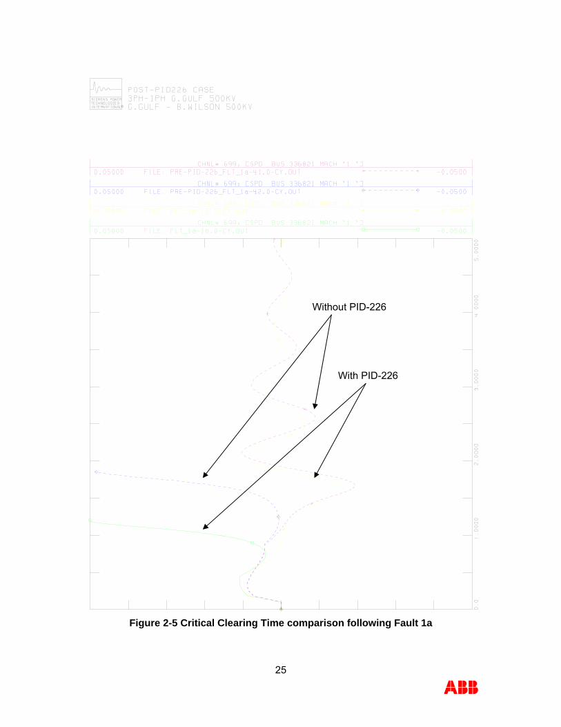
Figure 2-5 Critical Clearing Time comparison following Fault 1a
Without PID-226
With PID-226
25
ABB

Figure 2-6 Critical Clearing Time comparison following Fault 2b
Without PID-226
With PID-226
26
ABB

3 CONCLUSIONS Southwest Power Pool, Inc (SPP) at the request of Entergy Services Inc. has commissioned ABB Inc. to perform a stability analysis for Facility study of PID-226, which is a request for 206 MW uprate of existing G. Gulf Unit #1 in the Entergy transmission system. A system impact study for the PID-226 has previously been completed. The objective of this study was to supplement the stability analysis performed in the system impact study for PID-226 Project. To that end, selected faults at G. Gulf 500 kV substation were simulated and a Critical Clearing Time Analysis was performed at G. Gulf 500 kV substation. The study was performed on 2012 Summer Peak case, provided by SPP/Entergy. The system was stable following all simulated normally cleared and stuck-breaker faults. No voltage criteria violation was observed following simulated faults. The Critical Clearing times at G. Gulf 500 kV substations are within the capabilities of the existing protection systems. The smallest CCT at G. Gulf 500 kV substation was 5 + 15 cycles for a fault involving loss of G. Gulf – B. Wilson 500 kV. Based on the results of stability analysis it can be concluded that proposed PID-226 project does not adversely impact the stability of the Entergy System in the local area. Also, PID-226 does not adversely impact the Critical Clearing time at G. Gulf 500 kV substations. Hence, no transmission reinforcements and/ or upgrades were identified for the interconnection of the PID-226 project. The results of this analysis are based on available data and assumptions made at the time of conducting this study. If any of the data and/or assumptions made in developing the study model change, the results provided in this report may not apply.
27
ABB

APPENDIX A DATA PROVIDED BY CUSTOMER
28
ABB

29
ABB

30
ABB

31
ABB

32
ABB

33
ABB

34
ABB

35
ABB

36
ABB

37
ABB

38
ABB

39
ABB

40
ABB

41
ABB

42
ABB

APPENDIX B LOAD FLOW AND STABILITY DATA IN PSSE FORMAT
Loadflow Data 336821,'1 ', 1544.000, 0.000, 330.000, -330.000,1.02000,336820, 1600.000, 0.003656, 0.2880, 0.00000, 0.00000,1.00000,1, 100.0, 1544.000, 150.000, 1,1.0000 0 / END OF GENERATOR DATA, BEGIN BRANCH DATA 0 / END OF BRANCH DATA, BEGIN TRANSFORMER DATA 336820,336821, 0,'1 ',1,2,1, 0.00000, 0.00000,2,' ',1, 1,1.0000 0.0035, 0.1627, 1650.00 1.00000, 0.000, 0.000, 1650.00, 1650.00, 1650.00, 0, 0, 1.07500, 0.97500, 1.07500, 0.97500, 5, 0, 0.00000, 0.00000 1.00000, 0.000 0 / END OF TRANSFORMER DATA, BEGIN AREA DATA 0 / END OF AREA DATA, BEGIN TWO-TERMINAL DC DATA 0 / END OF TWO-TERMINAL DC DATA, BEGIN VSC DC LINE DATA 0 / END OF VSC DC LINE DATA, BEGIN SWITCHED SHUNT DATA 0 / END OF SWITCHED SHUNT DATA, BEGIN IMPEDANCE CORRECTION DATA 0 / END OF IMPEDANCE CORRECTION DATA, BEGIN MULTI-TERMINAL DC DATA 0 / END OF MULTI-TERMINAL DC DATA, BEGIN MULTI-SECTION LINE DATA 0 / END OF MULTI-SECTION LINE DATA, BEGIN ZONE DATA 0 / END OF ZONE DATA, BEGIN INTER-AREA TRANSFER DATA 0 / END OF INTER-AREA TRANSFER DATA, BEGIN OWNER DATA 0 / END OF OWNER DATA, BEGIN FACTS DEVICE DATA 0 / END OF FACTS DEVICE DATA
Dynamics Data REPORT FOR ALL MODELS BUS 336821 [GGULF 21.000] MODELS ** GENROU ** BUS X-- NAME --X BASEKV MC C O N S S T A T E S 336821 GGULF 21.000 1 130656-130669 51167-51172 MBASE Z S O R C E X T R A N GENTAP 1600.0 0.00366+J 0.28800 0.00000+J 0.00000 1.00000 T'D0 T''D0 T'Q0 T''Q0 H DAMP XD XQ X'D X'Q X''D XL 6.29 0.047 0.38 0.123 4.51 0.00 1.5510 1.4730 0.4170 0.8320 0.2880 0.2450 S(1.0) S(1.2) 0.2000 0.5000 ** PSS2A ** BUS X-- NAME --X BASEKV MC C O N S S T A T E S V A R S I C O N S 336821 GGULF 21.000 1 130670-130686 51173-51188 8396-8399 4483-4488 IC1 REMBUS1 IC2 REMBUS2 M N 1 0 3 0 5 1 TW1 TW2 T6 TW3 TW4 T7 KS2 KS3 2.000 2.000 0.000 2.000 0.000 2.000 0.202 1.000 T8 T9 KS1 T1 T2 T3 T4 VSTMAX VSTMIN 0.500 0.100 8.000 0.150 0.030 0.150 0.030 0.100 -0.100 ** ESAC5A ** BUS X-- NAME --X BASEKV MC C O N S S T A T E S VAR 336821 GGULF 21.000 1 130687-130701 51189-51193 8400 TR KA TA VRMAX VRMIN KE TE KF TF1 TF2 TF3 0.200 600.00 0.100 6.400 -6.400 1.000 0.220 0.020 1.000 0.130 0.000 E1 S(E1) E2 S(E2) KE VAR 3.7000 0.7300 2.8000 0.7300 0.0000
43
ABB

** IEEEG1 ** BUS X-- NAME --X BASEKV MC C O N S S T A T E S V A R S 336821 GGULF 21.000 1 130702-130721 51194-51199 8401-8402 K T1 T2 T3 UO UC PMAX PMIN T4 K1 12.00 0.000 0.000 0.075 0.600 -0.600 0.9700 0.0000 0.250 0.350 K2 T5 K3 K4 T6 K5 K6 T7 K7 K8 0.000 2.750 0.650 0.000 0.000 0.000 0.000 0.000 0.000 0.000
44
ABB

45
ABB
APPENDIX C PLOTS FOR STABILITY SIMULATIONS