Embed Size (px)
Citation preview

Proceedings of the
Annual Stability Conference
Structural Stability Research Council
Toronto, Canada, March 25-28, 2014
Stability of energy-dissipating steel fuses in an innovative
seismic system for cold-formed steel structures
R. Comini1, B.W. Schafer
2
Abstract
This paper describes modeling directed toward the development of an innovative energy-
dissipating seismic system for buildings framed from cold-formed steel members. The system
consists of shear walls with integrated butterfly-shaped steel links designed to yield under
seismic action, thus acting as replaceable energy-dissipating fuses. The shear deformation of the
wall under lateral seismic action induces shear and bending in the fuse links. The links yield
nearly uniformly along their length due to their butterfly shape. However, the significant
slenderness of the fuses, when sized for cold-formed steel structural applications, can make them
prone to buckling; and, instability of the fuses is detrimental as it decreases their energy-
dissipation capacity. The effect of buckling on the hysteretic response of the fuses and a cold-
formed steel framed wall with fuses is investigated, and numerical simulations using a
commercial finite-element software are carried out for both single steel links and an entire shear
wall system. Parametric studies on single fuse links are performed to investigate their behavior
and to estimate the occurrence of buckling. Formulas are provided to allow for selecting the
number and size of fuses necessary to achieve a targeted seismic performance in terms of
capacity and critical drift. The numerical results obtained by modeling the shear wall system
with fuses show that a significantly improved hysteretic behavior, compared to conventional
cold-formed steel framing sheathed with wood structural panels, can be achieved if fuse buckling
is prevented. This demonstrates the potential feasibility of the new system in the construction
industry. The paper also lays the foundations for future work, including dynamic analysis of a
full building model with the proposed seismic system, and laboratory testing of shear walls with
fuses to further validate the exploratory findings presented here.
1. Introduction
Cold-formed steel is an increasingly common material for building structures, not only for
traditional low-rise but also for mid-rise construction, which require seismic protection systems
complying with larger energy-dissipation demand. The primary lateral force resisting system for
1 Visiting Graduate Student, Johns Hopkins University, <[email protected]>
1 M.S. Student, Technical University of Denmark, <[email protected]>
1 M.S. Student, University of Padua, <[email protected]>
2 Professor and Chair, Johns Hopkins University, <[email protected]>
2
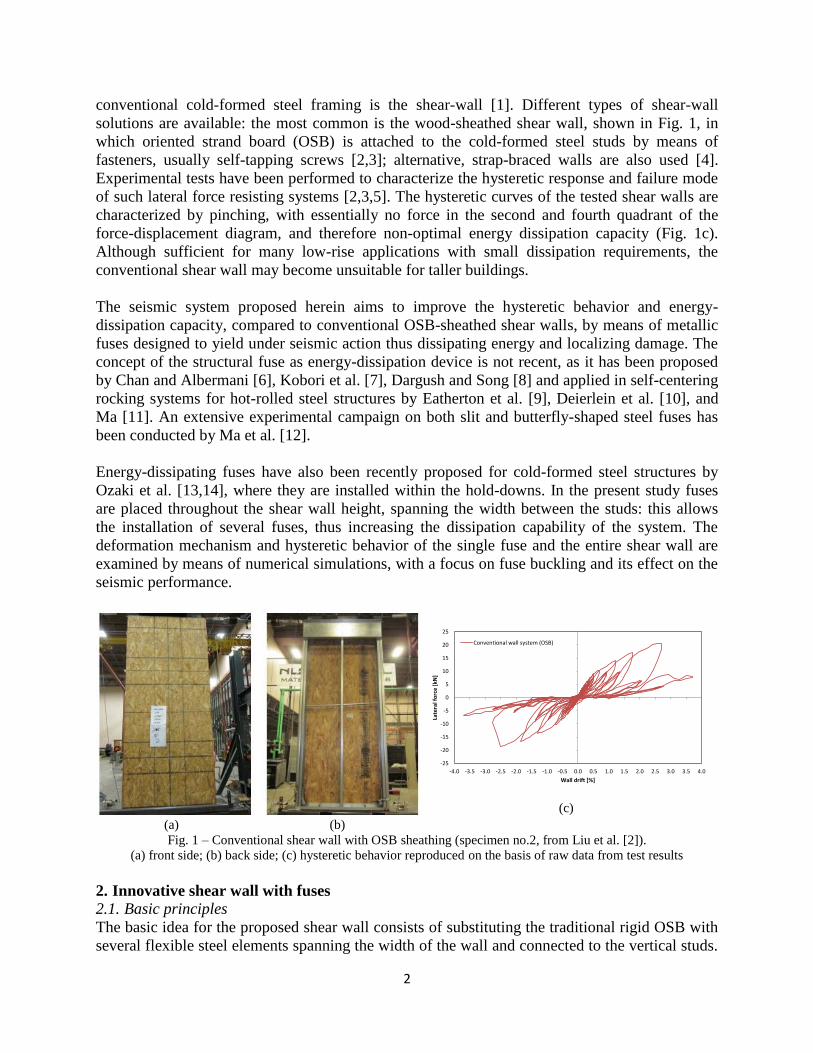
conventional cold-formed steel framing is the shear-wall [1]. Different types of shear-wall
solutions are available: the most common is the wood-sheathed shear wall, shown in Fig. 1, in
which oriented strand board (OSB) is attached to the cold-formed steel studs by means of
fasteners, usually self-tapping screws [2,3]; alternative, strap-braced walls are also used [4].
Experimental tests have been performed to characterize the hysteretic response and failure mode
of such lateral force resisting systems [2,3,5]. The hysteretic curves of the tested shear walls are
characterized by pinching, with essentially no force in the second and fourth quadrant of the
force-displacement diagram, and therefore non-optimal energy dissipation capacity (Fig. 1c).
Although sufficient for many low-rise applications with small dissipation requirements, the
conventional shear wall may become unsuitable for taller buildings.
The seismic system proposed herein aims to improve the hysteretic behavior and energy-
dissipation capacity, compared to conventional OSB-sheathed shear walls, by means of metallic
fuses designed to yield under seismic action thus dissipating energy and localizing damage. The
concept of the structural fuse as energy-dissipation device is not recent, as it has been proposed
by Chan and Albermani [6], Kobori et al. [7], Dargush and Song [8] and applied in self-centering
rocking systems for hot-rolled steel structures by Eatherton et al. [9], Deierlein et al. [10], and
Ma [11]. An extensive experimental campaign on both slit and butterfly-shaped steel fuses has
been conducted by Ma et al. [12].
Energy-dissipating fuses have also been recently proposed for cold-formed steel structures by
Ozaki et al. [13,14], where they are installed within the hold-downs. In the present study fuses
are placed throughout the shear wall height, spanning the width between the studs: this allows
the installation of several fuses, thus increasing the dissipation capability of the system. The
deformation mechanism and hysteretic behavior of the single fuse and the entire shear wall are
examined by means of numerical simulations, with a focus on fuse buckling and its effect on the
seismic performance.
(a)
(b)
(c)
Fig. 1 – Conventional shear wall with OSB sheathing (specimen no.2, from Liu et al. [2]).
(a) front side; (b) back side; (c) hysteretic behavior reproduced on the basis of raw data from test results
2. Innovative shear wall with fuses
2.1. Basic principles
The basic idea for the proposed shear wall consists of substituting the traditional rigid OSB with
several flexible steel elements spanning the width of the wall and connected to the vertical studs.
-25
-20
-15
-10
-5
0
5
10
15
20
25
-4.0 -3.5 -3.0 -2.5 -2.0 -1.5 -1.0 -0.5 0.0 0.5 1.0 1.5 2.0 2.5 3.0 3.5 4.0
Late
ral f
orc
e [
kN]
Wall drift [%]
Conventional wall system (OSB)
3
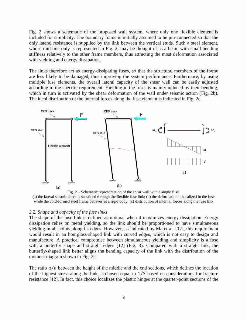
Fig. 2 shows a schematic of the proposed wall system, where only one flexible element is
included for simplicity. The boundary frame is initially assumed to be pin-connected so that the
only lateral resistance is supplied by the link between the vertical studs. Such a steel element,
whose mid-line only is represented in Fig. 2, may be thought of as a beam with small bending
stiffness relatively to the other frame members, thus attracting the most deformation associated
with yielding and energy dissipation.
The links therefore act as energy-dissipating fuses, so that the structural members of the frame
are less likely to be damaged, thus improving the system performance. Furthermore, by using
multiple fuse elements, the overall lateral capacity of the shear wall can be easily adjusted
according to the specific requirement. Yielding in the fuses is mainly induced by their bending,
which in turn is activated by the shear deformation of the wall under seismic action (Fig. 2b).
The ideal distribution of the internal forces along the fuse element is indicated in Fig. 2c.
(a)
(b)
(c)
Fig. 2 – Schematic representation of the shear wall with a single fuse.
(a) the lateral seismic force is sustained through the flexible fuse link; (b) the deformation is localized in the fuse
while the cold-formed steel frame behaves as a rigid body; (c) distribution of internal forces along the fuse link
2.2. Shape and capacity of the fuse links
The shape of the fuse link is defined as optimal when it maximizes energy dissipation. Energy
dissipation relies on metal yielding, so the link should be proportioned to have simultaneous
yielding in all points along its edges. However, as indicated by Ma et al. [12], this requirement
would result in an hourglass-shaped link with curved edges, which is not easy to design and
manufacture. A practical compromise between simultaneous yielding and simplicity is a fuse
with a butterfly shape and straight edges [12] (Fig. 3). Compared with a straight link, the
butterfly-shaped link better aligns the bending capacity of the link with the distribution of the
moment diagram shown in Fig. 2c.
The ratio ⁄ between the height of the middle and the end sections, which defines the location
of the highest stress along the link, is chosen equal to ⁄ based on considerations for fracture
resistance [12]. In fact, this choice localizes the plastic hinges at the quarter-point sections of the
0M0M
V V
V
M

4
links ( ⁄ ), away from the end and mid sections that are the most vulnerable to fracture due
to the stress concentration induced by geometric changes (corners).
The relationship between shear V and end moments is obtained by equilibrium of the fuse:
02MV
L (1)
where L is the length of the link. The shear force , causing first yielding at the quarter-point
sections, is:
28
27
y
y
t bV
L
(2)
where t is the thickness and the yield stress. The moment causing plastic hinges, for a
rectangular cross section, is 50% larger than the moment causing first yielding in the same
section, and therefore the maximum shear force the fuse can sustain is obtained by multiplying
Eq. (2) by 1.5, which gives the shear capacity:
24
9
y
fuse
t bV
L
(3)
Fig. 3 – Optimal butterfly-shaped fuse link, with nearly uniform yielding along its length and ratio chosen to
localize first yielding and first plastic hinges at the quarter-point sections, to increase its fracture resistance
2.3. Statics of the shear wall
A fundamental parameter for designing the shear wall with integrated fuses is the total lateral
capacity of the wall, ̅ hereinafter. A simplified relationship to estimate ̅ on the basis of
number and size of fuses can be derived from the global equilibrium of the frame, assumed to be
pin-connected (Fig. 4). In such a case, the lateral force F induced by seismic action can only be
sustained by the shear force V developed in the fuses and transferred to the foundation through
axial force N in the studs. From basic equilibrium considerations, the axial force at the bottom of
the studs is expressed by:
F h
Nw
(4)
a b
L
x
4L
V V
0M 0M
1
3
a
b

5
where h and w are, respectively, the height and the width of the frame. The shear force V in each
fuse is therefore related to the total lateral force F by the following expression:
1
fuse fuse
N F hV
n w n
(5)
where is the number of identical links installed in the wall. By rearranging Eq. (5) and
substituting ̅ , the maximum lateral capacity of the wall is found:
fuse
wall fuse
V wF n
h
(6)
However, an actual cold-formed steel frame is not pin-connected but fixed to the foundation by
means of hold-downs, which resist overturning moments. Thus, the frame provides extra
capacity that, when added to Eq. (6), gives a more realistic expression for a preliminary
design of the wall system:
fuse
wall frame fuse
V wF F n
h
(7)
Eq. (7), together with the fuse capacity expressed by Eq. (3), allows for selection of the number
and size of fuses to achieve a targeted lateral resistance for the shear wall.
Fig. 4 – Static equilibrium of the simplified shear wall with fuses:
the lateral seismic force F is resisted by the shear force V in the fuse links
2.4. Kinematics of the shear wall
To analyze the fuse response separately from the entire wall system, it is necessary to determine
the relationship between the overall deformation of the frame and the corresponding deformation

6
of the fuses. In this way, an equivalent loading protocol can be applied to the single fuses,
reproducing the same loading conditions they undergo when installed within the shear wall.
Seismic loading causes shear deformation of the wall, described by the lateral drift Δ that
approximately corresponds to the inclination angle of the studs:
[ ]topu
radh
(8)
where is the lateral displacement of the top track, and h the height of the frame. If the fuse
links span the entire width of the frame, their end section only undergoes the rotation angle
, and their local drift is equal to the drift of the wall . If, instead, side plates with
length are used to connect the fuses to the studs, each end of the link undergoes the
vertical displacement as well (Fig. 5). The total relative displacement between the two
fuse ends is therefore:
plate plateu L L L u w w (9)
where Eq. (8) has been used to simplify. The local drift of the fuse, by definition equal to
(Fig. 5), is therefore amplified compared to the drift of the wall, according to:
fuse
u w
L L (10)
Thus, to reproduce on the single link the same loading condition it would undergo if installed
within the shear wall, both rotation and vertical displacement have to be applied to the end
sections of the link, as schematically depicted in Fig. 5. Note, in all previous considerations the
fuse link was assumed to be much more flexible than side plates and vertical studs, thus
attracting almost the entire deformation.
Fig. 5 – Deformation of the fuse link with side plates under seismic action
(the fuse link is approximated by its mid-line, in red)

7
3. Numerical models of fuse links
A parametric study employing shell finite element models of single fuses under cyclic loading
has been carried out. The main objectives of the study were to verify the actual fuse capacity
expressed by Eq. (3), to determine hysteretic and deformation behavior of the fuses, and to
derive a formula for estimating their critical drift (i.e., the drift initiating buckling).
The fuse parameters analyzed are length L, height b of the end sections, thickness t and yield
stress . Sixty different links have been modeled by combining the following values:
;
;
;
.
3.1. Loading protocol and modeling techniques
The fuse models are subjected to cyclic loading protocols reproducing the same loading
conditions they would undergo when installed and tested within the shear wall. The seismic
performance of the wall system, in terms of hysteretic behavior and dissipation capacity, can be
evaluated by appropriate protocols capable of replicating the cumulative damage induced by
seismic action [15]. Here, the FEMA loading protocol [16] has been used, applied with
displacement control in a quasi-static way: the wall drift has been used as the deformation
control parameter because it is significant for evaluating the effects of earthquakes on building
structures. The protocol consists of repeated cycles with increasing amplitude, and for each
amplitude two identical cycles are completed. The targeted maximum drift , which should
correspond to initiation of the most severe damage, has been chosen equal to 2.5% based on
historical prescriptive requirements for cold-formed steel framing [17]. The amplitude of the
preceding cycles has been defined according to the FEMA document [16], as indicated in Fig. 6.
Up to two further steps have been added if any evident damage state (fuse buckling) has not
occurred before .
If the loading history on the entire wall is expressed by ( ), equivalent conditions on the
single fuse links are obtained, based on Section 2.4, by applying the following loading history to
the link end sections (Fig. 7):
( ) ( )
( ) ( ) ( )2
plate
t t
w Lu t t L t
(11)
where indicates the rotation and u the vertical displacement of each link end section.

8
Cycle N
1 0.12
2 0.17
3 0.24
4 0.33
5 0.47
6 0.65
7 0.91
8 1.28
9 1.79
10 2.50
11 3.25
12 4.00
(a)
(b)
Fig. 6 – (a) drift amplitude, in terms of wall drift, of the FEMA loading protocol;
(b) loading history comprehensive of two eventual extra-cycles after
Fig. 7 – Finite element mesh and loading conditions of the fuse link
The fuses are modeled by means of general-purpose shell elements S4R with reduced integration
(four nodes at the corners and one integration point at the center) and linear interpolation
between nodes: the commercial finite element software Abaqus [18] is used for all simulations.
To accurately describe the twisting deformation associated with instability of the fuses, eight
elements are seeded along the short edges, and the number of elements along the long edges aims
to keep the aspect ratio of each element close to one (Fig. 7). All degrees of freedom at the two
end sections of the fuse links are fixed, except for in-plane rotation and vertical displacement
u. The material model is elastic-perfectly plastic, which neglects eventual hardening and failure
associated with cracking.
Geometric imperfections are applied to the initial geometry to both replicate the flaws present in
reality and prevent numerical issues associated with bifurcation when buckling occurs. The
imperfection shape resembles that of the lowest buckling eigenmode of the fuse (obtained from
linear eigenvalue analyses) and the magnitude is taken equal to , which is the classical
imperfection value associated with global buckling modes [19].
3.2. Deformation and buckling of the fuses
The fuses, installed within the shear wall, initially deform in double-bending remaining in their
own plane. Their butterfly shape induces first yielding at the external fibers of the quarter-point
sections, and yielding immediately extends to the adjacent sections as well (Fig. 8). For larger
-4.0
-3.5
-3.0
-2.5
-2.0
-1.5
-1.0
-0.5
0.0
0.5
1.0
1.5
2.0
2.5
3.0
3.5
4.0
Wal
l dri
ft [
%]
Initial 10 steps
First additional step
Second additional step

9
drifts, the capacity ̅ is reached and plastic hinges form at the quarter-point sections (Fig. 9):
up to this point the fuse behavior is stable and no evident out-of-plane displacements are visible
(Fig. 10). However, when the drift increases further instability occurs as shown in Fig. 11 and
Fig. 12.
Fig. 8 – First yielding at the external fibers of the quarter-point sections.
The area where the stress has reached the yield stress is highlighted in red (stresses in Pascal)
Fig. 9 – Plastic hinges at the quarter-point sections.
The area where the stress has reached the yield stress is highlighted in red (stresses in Pascal)
Fig. 10 – Top view of the fuse before buckling (out-of-plane displacement in meters)
Fig. 11 – Buckling of the fuse with extensive plastic regions due to out-of-plane bending (stresses in Pascal)
Fig. 12 – Top view of the fuse after buckling (out-of-plane displacement in meters)
Lateral torsional buckling is the expected instability mode for elements loaded in major-axis
bending like the fuses; however, the full buckling mechanism is more complex. In fact, since the
critical load is significantly larger than the shear capacity, plastic behavior would anticipate
(Avg: 75%)SNEG, (fraction = -1.0)
S, Mises
-1.790e+08-1.492e+08-1.193e+08-8.950e+07-5.967e+07-2.983e+07+4.000e+00+2.983e+07+5.967e+07+8.950e+07+1.193e+08+1.492e+08+1.790e+08+1.800e+08
(Avg: 75%)SNEG, (fraction = -1.0)
S, Mises
-1.790e+08-1.492e+08-1.193e+08-8.950e+07-5.967e+07-2.983e+07+4.000e+00+2.983e+07+5.967e+07+8.950e+07+1.193e+08+1.492e+08+1.790e+08+1.800e+08
U, U3
-5.293e-05-4.411e-05-3.529e-05-2.647e-05-1.764e-05-8.822e-06-1.619e-10+8.821e-06+1.764e-05+2.646e-05+3.529e-05+4.411e-05+5.293e-05
(Avg: 75%)
SNEG, (fraction = -1.0)
S, Mises
+1.573e+07+2.933e+07+4.294e+07+5.654e+07+7.015e+07+8.376e+07+9.736e+07+1.110e+08+1.246e+08+1.382e+08+1.518e+08+1.654e+08+1.790e+08+1.800e+08
U, U3
-8.858e-03-7.381e-03-5.905e-03-4.429e-03-2.953e-03-1.476e-03-8.149e-09+1.476e-03+2.953e-03+4.429e-03+5.905e-03+7.381e-03+8.858e-03

10
and theoretically prevent instability. The expansion of the plastic hinges transforms the link into
three joined pieces, of which the central part nearly behaves like a pin-connected column, where
tension field develops due to stretching and elongation. Under increasing monotonic loading,
buckling does not occur even for very large drift, because it is prevented by the tension in the
central “column”. However, load reversal typical of cyclic protocols induces compressive
stresses that allow occurrence of lateral torsional buckling (Fig. 11). When the loading further
increases, the central link part is subjected to an instability mode similar to flexural buckling of
compressed elements. Instability generally precipitates large out-of-plane displacements (Fig.
12), drop of the fuse capacity and ensuing pinching of its hysteretic curve (Fig. 13).
Nevertheless, even in the post-buckling stage, large drifts produce tension in the central column
so that the fuse strength starts picking up again, as Fig. 13 shows.
Fig. 13 – Hysteretic curve of one of the fuse links (L=300mm; b=60mm; t=5mm; =180MPa).
Buckling of the fuse results in strength degradation and evident pinching of the hysteretic curves
It should be noted that the fuse critical drift depends on the magnitude of the
imperfections. Furthermore, the presence of imperfections makes evaluation of buckling less
straightforward due to the absence of a sharp bifurcation point, as in perfect structures. The
criterion followed to evaluate buckling is based on the negative stiffness of the load-deformation
curve: it is assumed that instability has occurred when the ratio between load and deformation
increments is, for the first time, negative. Since such negative stiffness always occurs after load
reversal, for a drift smaller than the previous peaks, the buckling drift is then defined as the
maximum peak before initiation of instability.
3.3. Buckling estimation
As fuse instability is associated with pinching of the hysteretic curves and is therefore
detrimental to the energy-dissipation capacity of the entire shear wall, a formula for estimating
is required. With such formula one can choose fuse dimensions to ensure stable
dissipation behavior up to the desired drift. No analytical expression is available to evaluate
buckling drift for butterfly-shaped elements; thus, the numerical results for the 60 fuses analyzed
are interpolated for this purpose. To obtain an evident trend, the normalized critical drift has
been plotted against the fuse slenderness , defined as:
-5
-4
-3
-2
-1
0
1
2
3
4
5
-6 -5 -4 -3 -2 -1 0 1 2 3 4 5 6
She
ar [
kN]
Fuse drift [%]

11
y
cr
V
V (12)
where is given by Eq. (2) and is the critical load obtained by an eigenvalue analysis. The
fuse slenderness is expected to be inversely proportional to buckling resistance. The critical drift
is conveniently normalized by the yielding drift (drift at which the fuse starts to
yield), in analogy with Eq. (12). A simplified expression for , obtained from the stiffness
coefficients of an equivalent straight fuse, is given by:
,
y
y fuse
L
E b
(13)
where E is the Young modulus. The normalized critical drift can be therefore defined as:
,
,
cr fuse
y fuse
(14)
Fig. 14 shows the numerical results for all 60 models analyzed where, despite the approximations
introduced, a clear trend can be seen, which is interpolated by a power law as indicated in the
figure. If the exponent is approximated to 1, the equation represents the branch of a rectangular
hyperbola, and:
0.57
(15)
which can be rewritten in terms of critical drift by substituting Eq. (12) and Eq. (14):
,
, 0.57y fuse cr
cr fuse
y
V
V
(16)
The maximum drift any butterfly-shaped fuse can sustain before buckling can therefore be
estimated, and Eq. (10) allows one to determine the corresponding lateral drift of the wall as
well. Since generally the maximum drift of cold-formed shear walls does not exceed 2-3%, the
fuse dimension should be chosen to ensure stable behavior until such drift level. As expected,
buckling resistance is inversely proportional to fuse slenderness.

12
Fig. 14 – Numerical interpolation of the critical drifts obtained in the numerical models of single fuses,
to derive a generalized formula for the buckling drift
4. Numerical model of the shear wall with fuses
A numerical model of the entire shear wall with fuses is presented in the following to
demonstrate the effectiveness of the proposed seismic system. The lateral capacity, hysteretic
behavior and energy-dissipation performance of the shear wall are evaluated and compared to a
conventional OSB-sheathed shear wall. For this purpose, geometric dimensions and cold-formed
steel members are chosen similar to those employed in the experiments of Liu et al. [2].
4.1. Modeling description
The width of the shear wall (distance between the center-lines of the back-to-back studs) is
, and the height . The aspect ratio is modestly smaller than 4, as
recommended in the AISI Standard [20]. Back-to-back studs 600S200-97 (50ksi) are used, which
are among the largest employed in current building practice; the top track 600T200-97 (50ksi) is
chosen accordingly (the nomenclature of the cold-formed steel members is based on an AISI
Standard [21]).
The members used for the model of the innovative seismic wall are slightly stronger compared to
those employed in the experimental tests [2]. The chord studs are built-up members made of two
600S200-97 connected together back-to-back (Fig. 15a): in actual frames, the built-up members
are realized by screw-connecting their webs together, but for simplicity the entire webs have
been tied together here (tie constraint in Abaqus [18]). Such a choice is not conservative, because
it introduces composite bending action of the webs and prevents independent local buckling of
the two members, but is justified here as the main focus is on fuse deformation and overall
performance of the shear wall.
To model the hold-down fasteners fixed boundary conditions have been applied, on the inward
face at the bottom of the chord studs, to a surface approximately equal to the surface of the hold-
downs. The top track (Fig. 15b) has been restrained against transverse displacements to force in-
plane behavior of the system; the stud-to-track joints are assumed to be moment-resisting and
therefore modeled by means of tie-constraints.
δ = 0.57/λ1.03
R² = 0.89
0
1
2
3
4
5
6
7
8
9
10
11
12
13
14
15
0 0.05 0.1 0.15 0.2 0.25
δ(n
orm
aliz
ed
cri
tica
l dri
ft)
λ (fuse slenderness)

13
Similarly to the fuses, S4R shell elements with four nodes and reduced integration [18] define
the finite element mesh of the thin cold-formed steel members. Two elements have been used
along the lips of the studs, which is the minimum required to approximate local buckling at the
lips. The number of elements for the flanges and web ensure an aspect ratio close to one. An
elastic-perfectly plastic material model is employed, with yield stress ( ).
The FEMA loading protocol [16], already described for the single fuse models, is applied to the
frame with displacement-control. This is completed by imposing the proper displacement history
along the longitudinal axis to all nodes of the end cross-section of the track (Fig. 15b). Any
loading eccentricity is therefore prevented.
(a)
(b)
Fig. 15 – Finite element mesh of the back-to-back studs (a) and top track (b)
4.2. Fuse links and connection to the studs
In the model of the shear wall presented herein, the fuses indicated in Fig. 16 are used. The fuse
links are flanked by two side plates for connection to the studs. Nine fuses are installed within
the shear wall (Fig. 17a), to provide lateral capacity similar to the capacity of the walls tested by
Liu et al. [2]. Different solutions can be employed for the actual connection of the fuses to the
studs; here, for simplicity, tie-constraints (allowing for moment-transfer) are applied between the
end section of the side plates and the web of the studs. Although convenient for simple modeling,
this solution is not optimal for practical implementation, and the small out-of-plane bending
resistance of the web may cause localized deformation in the studs. However, for the present
example this connection detail is not the focus, and is designed primarily to minimize its impact
on the overall performance of the system.
400
60
7
180y
L mm
b mm
t mm
MPa
Fig. 16 – Fuse type used for the seismic wall presented in the example (dimensions in mm)

14
4.3. Seismic response of the shear wall
The maximum lateral capacity ̅ sustained by the shear wall shown in Fig. 17a is equal to
18.8kN, which is just 5% larger than the value estimated by the approximate formula (7):
5.04 0.7
6 9 17.82.7
fuse
wall frame fuse
V wF F n kN kN
h
(17)
Thus, Eq. (7) is a useful tool for the design of the seismic wall, in terms of lateral capacity. The
actual deformation behavior of the shear wall during cyclic deformation is shown in Fig. 17b: the
red areas indicate where the yield stress has been reached. As expected, the plastic deformation
is concentrated in the links and is associated with their bending behavior (see detail in Fig. 17c).
The rest of the structure, colored grey, remains practically undamaged.
The seismic performance of the shear wall, in terms of energy-dissipation capacity, can be
evaluated from its hysteretic behavior, shown in Fig. 18. Up to a wall drift of 2-2.5%, the
behavior is stable as the fuses deform in bending and yield in their own plane. However, for
larger drift, instability occurs as predicted by Eq. (16), which results in a decrease of capacity
and ensuing pinching of the hysteretic curves (Fig. 18). The wall behaves elastically up to a drift
of approximately 0.5%, after which the fuses start to yield and dissipate energy. Fuse buckling is
detrimental to the seismic performance of the system, because it reduces the energy dissipation,
although the capacity reduction in the first cycles after instability is not dramatic. The fuses
should guarantee stable behavior up to the desired drift but also prevent yielding and ensuing
damage for very small drift: for this purpose, Eq. (16) and Eq. (13), respectively, can be used.
(a)
(b)
(c)
Fig. 17 – (a) Three-dimensional Abaqus model of the shear wall with 9 fuses; (b) stable deformation behavior of the
shear wall, with yielding (red areas) localized in the fuses and the frame remaining in the elastic range; (c) detail of
bending deformation and yielding of two fuse links

15
Fig. 18 – Hysteretic behavior of the shear wall with 9 fuses, under the FEMA loading protocol [16]
4.4. Comparison with the conventional seismic wall
In this section the hysteretic behavior of the proposed seismic wall with fuses is compared to the
behavior of the conventional shear walls sheathed with OSB and tested by Liu et al. [2]. The wall
specimen used for the comparison is characterized by 11mm (7/16 in.) OSB on the front side,
attached to the studs and track by flat-head fasteners. The hysteretic curves of Fig. 1c and Fig. 18
are plotted together in Fig. 19. Although initial stiffness and maximum wall resistance are similar
for the two cases, the deformation mechanism and development of damage are significantly
different. The wall with OSB sustains most of the seismic action through localized bearing
damage at the fastener locations in the rigid wooden panel, and almost no force is left in the
system when the applied drift returns to zero. As a consequence, the hysteretic curves are narrow
and the energy dissipated is small. When, eventually, brittle failure occurs in the connections,
there is an evident reduction of capacity associated with significant pinching.
On the contrary, the wall with fuses sustains most of the seismic action through shear and
bending of the links, which yield quite early thus making the system capable of carrying residual
force even when the drift is back to zero. When instability occurs, the total capacity decreases
but the fuses can still absorb plastic energy. Since the hysteretic curves are large and extend to
the second and fourth quadrant of the load-drift diagram (Fig. 19), the energy dissipated is much
larger in this innovative system.
Fig. 19 – Comparison of the hysteretic behavior of the conventional OSB-sheathed frame
(reproduced from [2]) and the innovative shear wall with fuses
-25
-20
-15
-10
-5
0
5
10
15
20
25
-4.0 -3.5 -3.0 -2.5 -2.0 -1.5 -1.0 -0.5 0.0 0.5 1.0 1.5 2.0 2.5 3.0 3.5 4.0
Late
ral f
orc
e [
kN]
Wall drift [%]
Innovative wall system (fuses)
-25
-20
-15
-10
-5
0
5
10
15
20
25
-4.0 -3.5 -3.0 -2.5 -2.0 -1.5 -1.0 -0.5 0.0 0.5 1.0 1.5 2.0 2.5 3.0 3.5 4.0
Late
ral f
orc
e [
kN]
Wall drift [%]
Conventional wall system (OSB)
Innovative wall system (fuses)

16
5. Conclusions
Structural fuses installed within traditional cold-formed steel frames improve the seismic
performance in terms of hysteretic behavior and energy-dissipation capacity. A butterfly-shaped
link is an effective fuse, inducing uniform yielding along the fuse length and maximizing energy
dissipation. If properly designed, the fuses have smaller bending resistance than the studs and
therefore, under seismic action, attract most of deformation and reduce damage in the rest of the
shear wall. However, large bending in the fuse may cause lateral torsional buckling, which
reduces the fuse capacity and is detrimental to the seismic performance of the wall. An
approximate formula has been derived to estimate the buckling drift of the fuses, and
consequently of the shear wall. Once the fuses are damaged (e.g., after significant earthquakes),
they can be replaced thus allowing continued occupancy of the building. Stiffness and lateral
resistance of the shear wall can be adjusted by selecting the number and size of the fuse links,
and formulas are provided for preliminary design of such a system. Comparison with
conventional shear walls, sheathed with wooden panels, suggests that the proposed shear wall
can dramatically improve the seismic response of cold-formed steel structures. Further numerical
analyses (including dynamic simulations) and experimental tests are necessary before
implementation in the construction industry, but the concept has demonstrated promise.
References
[1] B. W. Schafer, "Cold-formed steel structures around the world – A review of recent advances in applications,
analysis and design," Steel Construction, vol. 3, 2011.
[2] P. Liu, K. D. Peterman, and B. W. Schafer, "Test report on cold-formed steel shear walls," 2012.
[3] K. D. Peterman and B. W. Schafer, "Hysteretic shear response of fasteners connecting sheathing to cold-formed
steel studs," 2013.
[4] M. Al-Kharat and C. A. Rogers, "Inelastic performance of cold-formed steel strap braced walls," Journal of
Constructional Steel Research, no. 63, pp. 460-474, 2007.
[5] O. Iuorio, L. Fiorino, V. Macillo, and R. Landolfo, "Seismic design and experimental tests of an Italian cold
formed steel structure," 2012.
[6] R.W.K Chan and F. Albermani, "Experimental study of steel slit damper for passive energy dissipation,"
Engineering Structures, no. 30, pp. 1058-1066, 2008.
[7] T. Kobori et al., "Development and Application of Hysteresis Steel Damper," in Earthquake Engineering,
Rotterdam, 1992.
[8] G. F. Dargush and T. T. Soong, "Behavior of Metallic Plate Dampers in Seismic Passive Energy Dissipation
Systems," Earthquake Spectra, vol. 11, no. 4, 1995.
[9] M. Eatherton et al., "Controlled rocking of steel-frame buildings with replaceable energy-dissipating fuses," in
The 14th World Conference on Earthquake Engineering, 2008.
[10] G. Deierlein et al., "Seismically resilient steel braced frame systems with controlled rocking and energy
dissipating fuses," in NSF Engineering Research and Innovation Conference, Honolulu, Hawaii, 2009.
[11] X. Ma, "Seismic design and behavior of self-centering braced frame with controlled rocking and energy-
dissipating fuses," 2010.
[12] X. Ma et al., "Design and behavior of steel shear plates with openings as energy-dissipating fuses," 2011.
[13] F. Ozaki, Y. Kawai, H. Tanaka, T. Okada, and R. Kanno, "Innovative damage control systems using
replaceable energy dissipating steel fuses for cold-formed steel structures," in Specialty Conference on Cold-
Formed Steel Structures, 2010.
[14] F. Ozaki, Y. Kawai, R. Kanno, and K. Hanya, "Damage-Control Systems Using Replaceable Energy-
Dissipating Steel Fuses for Cold-Formed Steel Structures: Seismic Behavior by Shake Table Tests," Journal of
Structural Engineering, no. 139, pp. 787-795, 2013.

17
[15] H. Krawinkler, "Loading histories for cyclic tests in support of performance assessment of structural
components,".
[16] Federal Emergency Management Agency, "Interim Testing Protocols for Determining the Seismic Performance
Characteristics of Structural and Nonstructural Components," 2007.
[17] American Society of Civil Engineers, ASCE 7 - Minimum Design Loads for Buildings and Other Structures.,
2002.
[18] SIMULIA, Abaqus Analysis User's Manual (version 6.11).
[19] V. M. Zeinoddini and B. W. Schafer, "Simulation of geometric imperfections in cold-formed steel members
using spectral representation approach," Thin-Walled Structures, 2012.
[20] American Iron and Steel Institute, "North American Standard for Cold-formed Steel Framing - Lateral design.
S213-07-SI-09," 2009.
[21] American Iron and Steel Institute, "North American Standard for Cold-formed Steel Framing - Product Data.
AISI S201-7," 2007.