Embed Size (px)
Citation preview
Abstract — The stability of perforated plates with an in-plane
pre-load at central circular opening were studied. Parametric
investigations were conducted by varying the diameter of opening
and the magnitude of in-plane force. The effect of aspect ratio
(edge-length to thickness) was examined. Three sets of numerical
models were prepared. First, the plate structures without any
openings (pristine) were simulated for critical buckling loads.
Results were verified with theoretical closed form solutions.
Second, circular openings were introduced on the same models
and simulations were repeated. Finally, all models were
simulated with in-plane pre-loads at cutouts. Plots representing
Eigen values versus plate slenderness ratio were presented.
Critical stresses for stability were calculated in relation to
applied in-plane load at cutouts. Finally, a design equation for
critical stress values was developed for a perforated plate.
Keywords—Buckling, Perforated plate, ABAQUS, Simply
supported, 316L.
Notation:
FE —Finite Element
LPS — Local Positioning System
SEL — Shell Edge Load
𝜎𝑐𝑟 — Critical stress for instability
𝜎𝑐𝑟𝑝
— Critical stress for instability with pre-load
𝜎𝑥 — Normal stress parallel to 𝑥 axis
𝑝𝑥 — Distributed load parallel to 𝑥 axis
𝐸 — Elastic Modulus
𝜗 — Poisson’s ratio
𝑡 — Thickness of plate
𝐾 — Plate buckling coefficient
𝐶 — Plate buckling coefficient for a perforated plate
𝑏 — Width of plate
𝑎 — Length of plate
𝜑 — Aspect ratio of plate (𝑎 𝑏 )
𝑆 — Slenderness ratio of plate (𝑎 𝑡 )
𝑚 — Number of Half-waves
𝑝𝑐𝑟 — Critical unit compressive force
𝑑 — Diameter of circular opening
𝑝𝑎 — Total force applied
𝐴𝑠𝑒𝑙 — Applied Shell Edge Load
𝑓 — Multiplication factor
Sathish Nammi, Jean-Luc Mauricette and Hassan Shirvani are with Anglia
Ruskin Universitya, Chelmsford, CM1 1SQ, UK (*Corresponding Author
Phone: 0845-196-3900; [email protected]). Imran Patel is with
University of Hertfordshireb, Hatfield, AL10 9AB.
I. INTRODUCTION
The stability of structures is an important area in civil,
mechanical, marine, aerospace and many other fields of
engineering. Therefore structural stability problems can
manifest in a myriad of ways. The field of solid mechanics
examines many classic problems on stability criterion, and
there is an extensive literature available on fundamental
problems in applied mechanics [1], [2]. However, solutions to
problems with varying boundary conditions and various
possibilities of loads is a challenge, where there are many gaps
in knowledge. There are many facets to engineering problems
that require further study; one such area is in multi-loading
scenerios involving perforated plates. In this paper, a plate
without any cutout and with a cutout will be referred to as
pristine and perforated.
Most published information is largely on pristine plates,
whereas perforated plates are still an area requiring further
research, especially under complex loading scenerios. Most
literature on perforated plates pertain to loads subjected to
pure uniaxial, biaxial or shear loading ([3]-[4]). However,
problems involving how pre-loads on a centrally located
opening affect stability have not been given thorough attention
which the current investigations focus upon. The critical load
under edge compression is computed for specific dimensions
of a perforated plate. Investigations are limited to elastic
buckling cases with intention for future research to extend to
inelastic problems, with critical instability stresses examined
for various slenderness ratios of plates.
II. PROBLEM DESCRIPTION AND JUSTIFICATION OF RESEARCH
A schematic of a perforated rectangular perforated plate
lateral and longitudinal dimensions of 203.2 × 254𝑚𝑚2 and a
circular cutout at its centre is shown in Fig 1. Its critical
buckling stress diminishes when this plate is subjected to an
inplane distributed pre-load on the circular opening. The aim
is to develop an equation for critical buckling stress with a
known pre-load at its circular cutout. The plate shown in Fig 2
is of a blast resistant enclosure with its front face reinforced
with steel and Al foam designed to withstand low yield frontal
blast loading. Such reinforcements can be extended to one or
more faces depending on the requirements.
Stability of Perforated Plates with an In-plane
Pre-load on Central Cutout
Sathish Nammia*, Jean-Luc Mauricettea, Imran Patelb and Hassan Shirvania
Proceedings of the World Congress on Engineering 2016 Vol II WCE 2016, June 29 - July 1, 2016, London, U.K.
ISBN: 978-988-14048-0-0 ISSN: 2078-0958 (Print); ISSN: 2078-0966 (Online)
WCE 2016

The enclosures have the ability to with-stand high-pressure
loads generated in a typical explosion. It is the intention of this
research to build enclosures to protect sensor (viz: strain,
thermal, LPS and acceleration) and wireless waspnote units.
The back face shown in Fig 3 has a circular opening that
allows passing wiring harness, and also allows the fixing of
several sensors, antennas and media recording equipment, as
shown in Fig 4. The back face is pre-loaded due to the
mounting of aforementioned units causing the stress
distribution to change around the cutouts. In this regard, the
work described in this paper will go some way in developing
numerical solutions for critical loads for pre-loaded plates.
Fig 1: Problem description
Fig 2: Front and back faces of enclosure
Fig 3: Circular cutout on the back face of enclosure
Fig 4: Illustration of a pre-load to back face
III. ANALYTICAL THEORY
An analytical procedures on pristine plate with an edge-
compression is presented here in Fig 5 the longitudinal (𝑎) and
lateral (𝑏) edges are parallel to 𝑥 and 𝑦 axis respectively. This
plate is subjected to in-plane edge-load, with a uniformly
distributed load acting parallel to the 𝑥 axis given by:
𝑝𝑥 = 𝑡 𝜎𝑥 (1)
Theoretical critical buckling stress for this case involving
uniformly distributed edge compression on two opposite
edges, parallel to the 𝑦 axis, is given by [2]:
𝜎𝑐𝑟 = 𝐾𝜋2𝐸
12(1−𝜗2) 𝑡
𝑏
2
(2)
Here 𝐾 depends on ratio (𝜑) and number of half-waves
(𝑚) formed in the buckled configuration of plate, and is
defined by:
𝐾 = 𝜑
𝑚+
𝑚
𝜑
2
(3)
Proceedings of the World Congress on Engineering 2016 Vol II WCE 2016, June 29 - July 1, 2016, London, U.K.
ISBN: 978-988-14048-0-0 ISSN: 2078-0958 (Print); ISSN: 2078-0966 (Online)
WCE 2016
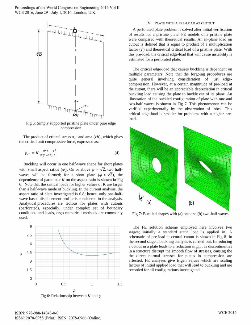
Fig 5: Simply supported pristine plate under pure edge
compression
The product of critical stress 𝜎𝑐𝑟 and area (𝑡𝑏), which gives
the critical unit compressive force, expressed as:
𝑝𝑐𝑟 = 𝐾𝜋2𝐸
12(1−𝜗2)
𝑡3
𝑏 (4)
Buckling will occur in one half-wave shape for short plates
with small aspect ratios (𝜑). On or above 𝜑 = 2, two half-
waves will be formed; for a short plate (𝜑 < 2), the
dependence of parameter 𝐾 on the aspect ratio is shown in Fig
6. Note that the critical loads for higher values of K are larger
than a half-wave mode of buckling. In the current analysis, the
aspect ratio of plate investigated is 0.8; hence, only one-half-
wave based displacement profile is considered in the analysis.
Analytical procedures are tedious for plates with cutouts
(perforated), especially, under complex set of boundary
conditions and loads, ergo numerical methods are commonly
used.
Fig 6: Relationship between 𝐾 and 𝜑
IV. PLATE WITH A PRE-LOAD AT CUTOUT
A perforated plate problem is solved after initial verification
of results for a pristine plate. FE models of a pristine plate
were compared with theoretical results. An in-plane load on
cutout is defined that is equal to product of a multiplication
factor (𝑓) and theoretical critical load of a pristine plate. With
this pre-load, the critical edge-load that will cause instability is
estimated for a perforated plate.
The critical edge-load that causes buckling is dependent on
multiple parameters. Note that the forgoing procedures are
quite general involving consideration of just edge-
compression. However, at a certain magnitude of pre-load at
the cutout, there will be an appreciable depreciation in critical
buckling load causing the plate to buckle out of its plane. An
illustration of the buckled configuration of plate with one and
two-half waves is shown in Fig 7. This phenomenon can be
verified experimentally by the observation of lobes. This
critical edge-load is smaller for problems with a higher pre-
load.
Fig 7: Buckled shapes with (a) one and (b) two-half waves
The FE solution scheme employed here involves two
stages; initially a standard static load is applied in. A
schematic of pre-load at central cutout is shown in Fig 8. In
the second stage a buckling analysis is carried-out. Introducing
a cutout in a plate leads to a reduction in 𝑝𝑐𝑟 , as discontinuities
in a structure distrupt the smooth flow of stresses, causing the
the direct normal stresses for plates in compression are
affected. FE analyses give Eigen values which are scaling
factors of initial applied load that will lead to buckling and are
recorded for all configurations investigated.
Proceedings of the World Congress on Engineering 2016 Vol II WCE 2016, June 29 - July 1, 2016, London, U.K.
ISBN: 978-988-14048-0-0 ISSN: 2078-0958 (Print); ISSN: 2078-0966 (Online)
WCE 2016

Fig 8: Illustration of a perforated plate with a pre-load at
cutout
Numerical code ABAQUS was used to conduct the
investigations with much of the parametric modelling
accomplished using PYTHON programming language scripts.
FE models with a range of slenderness ratios (40.6 to 225.7)
were prepared, with thickness varying between 0.9-5 mm. The
dimensions of the rectangular plates used in simulations are
detailed in Table I. Yield stress versus plastic strain properties
of 316L grade alloy used for FE model is in Table II, an
elastic modulus of 200 𝐺𝑃𝑎 and poisson’s ratio 0.3 were
assigned.
Table I: Plate thickness simulated
𝑡
(mm) 𝑎
(mm) 𝑏
(mm) 𝑎
𝑡
0.9 203.2 254 225.7
1.2 203.2 254 169.3
1.5 203.2 254 135.4
2.0 203.2 254 101.6
2.2 203.2 254 92.3
2.5 203.2 254 81.2
2.7 203.2 254 75.2
3.0 203.2 254 67.7
3.2 203.2 254 63.5
3.5 203.2 254 58.0
4.0 203.2 254 50.8
4.5 203.2 254 45.1
5.0 203.2 254 40.6
Table II: Plasticity data for 316L
Yield Stress (MPa) Plastic Strain
238.4 0.0
302.8 0.0078
383.9 0.0341
447.9 0.0642
501.6 0.092
594.1 0.146
669.6 0.1998
729.8 0.2516
780.4 0.3035
819.2 0.3559
The material properties were obtained from tensile testing
according to EN 10002-1. Note that only elastic properties
were considered in this paper. In literature [5] materials are
also assumed to deform plastically with no work hardening
after yield stress. Such models also referred to as the elastic
and perfectly plastic material model. FE models with two
cutout diameters of 20.32 and 40.64 𝑚𝑚 were considered.
They were descritized into a grid of quadrilateral shell
elements using adaptive meshing for modelling curvature
around the circular cutouts. A fine mesh was used in zones
around the cutout with the best mesh density gained from a
grid independence study. High aspect ratios (length to width
of elements) in the structured mesh were avoided to minimize
inaccuracies illustrated in Fig 9. The general-purpose shell (4-
NODE, S4R type ABAQUS [8]) elements that are capable of
bending, axial deformation and transverse shear were used.
Five integration points were used over the thickness for each
element.
Fig 9: Illustration of adaptive mesh (a) pristine (b) with cutout
It is assumed that the free edges on the boundary are simply
supported in an out-of-plane direction. The bottom end nodes
of FE model were constrained against any movement along
the global 𝑥 direction. So the boundary conditions reflect a
case of simply supported edge condition. An in-plane uniform
SEL is applied on the top edge based on the following
formulation:
𝐴𝑠𝑒𝑙 =𝜋2𝐸
12(1−𝜗2)
𝑡3
𝑏2 (5)
An illustration of the edge load applied is highlighted in Fig
10. The product of 𝐴𝑠𝑒𝑙 and Eigen values provided by the
buckling analysis, gives the critical Shell Edge Load (SEL) of
instability, for example a SEL of 2042.52 𝑁/𝑚 is obtained
from eq. (5) for a 0.9 𝑚𝑚 thick plate. The corresponding
buckling analysis produced an Eigen value of 4.24; in a
similar fashion an analysis is repeated for a perforated plate.
Proceedings of the World Congress on Engineering 2016 Vol II WCE 2016, June 29 - July 1, 2016, London, U.K.
ISBN: 978-988-14048-0-0 ISSN: 2078-0958 (Print); ISSN: 2078-0966 (Online)
WCE 2016

Eigen values of a plate of 20.32 𝑚𝑚 diameter (𝑑) cutout are
shown along side a pristine plate in Fig 11. An Eigen value of
4.2433 for the pristine plate is within 1% of theoretical result.
A lower value of 4.0652 was obtained for plate with a cutout.
A lower value in relation to a pristine plate is expected for
perforated as an opening reduces the strength of plate. The
critical shell edge-load that will cause instability therefore
is 2042.52 × 4.0652 = 8303.26 𝑁/𝑚. FE results of
perforated plates of cutout diameters (𝑑) 20.32 and 40.64 𝑚𝑚
were compared with a pristine plate. An in-plane uniform SEL
is applied on the top edge based on equation (5).
Corresponding critical Eigen values for various slenderness
ratios are shown in Fig 12. The Eigen values are nearly
constant independent of slenderness ratios for the cases
considered. The 𝐾 values for a perforated plate of thickness
0.9 mm and cutout diameter 20.32 mm is shown in Fig 13, a
reduction was noted with an increase in cutout diameter.
Fig 10: Illustration of edge load
Fig 11: Buckling analysis results of pristine (left) and perforated (right) plates
Fig 12: K values of models simulated
Fig 13: Effect of increasing the cutout dimeter
Proceedings of the World Congress on Engineering 2016 Vol II WCE 2016, June 29 - July 1, 2016, London, U.K.
ISBN: 978-988-14048-0-0 ISSN: 2078-0958 (Print); ISSN: 2078-0966 (Online)
WCE 2016
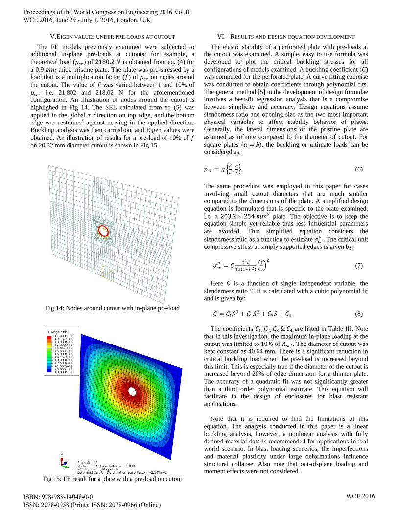
V. EIGEN VALUES UNDER PRE-LOADS AT CUTOUT
The FE models previously examined were subjected to
additional in-plane pre-loads at cutouts; for example, a
theoretical load (𝑝𝑐𝑟 ) of 2180.2 𝑁 is obtained from eq. (4) for
a 0.9 𝑚𝑚 thick pristine plate. The plate was pre-stressed by a
load that is a multiplication factor (𝑓) of 𝑝𝑐𝑟 on nodes around
the cutout. The value of 𝑓 was varied between 1 and 10% of
𝑝𝑐𝑟 . i.e. 21.802 and 218.02 N for the aforementioned
configuration. An illustration of nodes around the cutout is
highlighed in Fig 14. The SEL calculated from eq (5) was
applied in the global 𝑥 direction on top edge, and the bottom
edge was restrained against moving in the applied direction.
Buckling analysis was then carried-out and Eigen values were
obtained. An illustration of results for a pre-load of 10% of 𝑓
on 20.32 mm diameter cutout is shown in Fig 15.
Fig 14: Nodes around cutout with in-plane pre-load
Fig 15: FE result for a plate with a pre-load on cutout
VI. RESULTS AND DESIGN EQUATION DEVELOPMENT
The elastic stability of a perforated plate with pre-loads at
the cutout was examined. A simple, easy to use formula was
developed to plot the critical buckling stresses for all
configurations of models examined. A buckling coefficient (𝐶)
was computed for the perforated plate. A curve fitting exercise
was conducted to obtain coefficients through polynomial fits.
The general method [5] in the development of design formulae
involves a best-fit regression analysis that is a compromise
between simplicity and accuracy. Design equations assume
slenderness ratio and opening size as the two most important
physical variables to affect stability behavior of plates.
Generally, the lateral dimensions of the pristine plate are
assumed as infinite compared to the diameter of cutout. For
square plates (𝑎 = 𝑏), the buckling or ultimate loads can be
considered as:
𝑝𝑐𝑟 = 𝑔 𝑑
𝑎,𝑎
𝑡 (6)
The same procedure was employed in this paper for cases
involving small cutout diameters that are much smaller
compared to the dimensions of the plate. A simplified design
equation is formulated that is specific to the plate examined.
i.e. a 203.2 × 254 𝑚𝑚2 plate. The objective is to keep the
equation simple yet reliable thus less influencial parameters
are avoided. This simplified equation considers the
slenderness ratio as a function to estimate 𝜎𝑐𝑟𝑝
. The critical unit
compressive stress at simply supported edges is given by:
𝜎𝑐𝑟𝑝
= 𝐶𝜋2𝐸
12(1−𝜗2) 𝑡
𝑏
2
(7)
Here 𝐶 is a function of single independent variable, the
slenderness ratio 𝑆. It is calculated with a cubic polynomial fit
and is given by:
𝐶 = 𝐶1𝑆3 + 𝐶2𝑆
2 + 𝐶3𝑆 + 𝐶4 (8)
The coefficients 𝐶1,𝐶2, 𝐶3 & 𝐶4 are listed in Table III. Note
that in this investigation, the maximum in-plane loading at the
cutout was limited to 10% of 𝐴𝑠𝑒𝑙 . The diameter of cutout was
kept constant as 40.64 mm. There is a significant reduction in
critical buckling load when the pre-load is increased beyond
this limit. This is especially true if the diameter of the cutout is
increased beyond 20% of edge dimension for a thinner plate.
The accuracy of a quadratic fit was not significantly greater
than a third order polynomial estimate. This equation will
facilitate in the design of enclosures for blast resistant
applications.
Note that it is required to find the limitations of this
equation. The analysis conducted in this paper is a linear
buckling analysis, however, a nonlinear analysis with fully
defined material data is recommended for applications in real
world scenario. In blast loading scenerios, the imperfections
and material plasticity under large deformations influence
structural collapse. Also note that out-of-plane loading and
moment effects were not considered.
Proceedings of the World Congress on Engineering 2016 Vol II WCE 2016, June 29 - July 1, 2016, London, U.K.
ISBN: 978-988-14048-0-0 ISSN: 2078-0958 (Print); ISSN: 2078-0966 (Online)
WCE 2016

Table III: List of coefficients for design equation
In-plane load applied
at cutout
𝐶1 𝐶2
𝐶3
𝐶4
1% of 𝑓 3.6001 × 10⁻⁸ −1.7491 × 10⁻⁵ 2.7712 × 10⁻³ 3.8921
3% of 𝑓 3.6046 × 10⁻⁸ −1.7504 × 10⁻⁵ 2.7721 × 10⁻³ 3.8415
5% of 𝑓 3.5973 × 10⁻⁸ −1.7478 × 10⁻⁵ 2.7692 × 10⁻³ 3.7908
7% of 𝑓 3.608 × 10⁻⁸ −1.7516 × 10⁻⁵ 2.7735 × 10⁻³ 3.7398
10% of 𝑓 3.5971 × 10⁻⁸ −1.748 × 10⁻⁵ 2.7705 × 10⁻³ 3.6633
VII. CONCLUSIONS
Stability of plates containing circular cutouts subjected to
in-plane pre-loads at central opening were investigated. A
simplified design formula to estimate critical buckling loads
was successfully presented. This design equation can be
applied to a plate with a cutout diameter 20.32 𝑚𝑚. It is
demonstrated here there is a possibility of developing generic
formulae for any diameter cutout. To summarise:
o Both cutout diameter and in-plane pre-load affect the
critical buckling load. However, small in-plane pre-
loads on a diameter cutout (less than 10% longer
edge length) do not significantly reduce strength.
o The critical stress of instability of a plate always
decreases with increase in slenderness ratio and this
decrease is greater for larger diameter (more than
20% of edge 𝑎) cutout.
o Increasing the cutout diameter size to 20% of
longitudinal edge 𝑎, reduces buckling load by 11.4%
for a plate of aspect ratio 0.8.
ACKNOWLEDGMENT
This work was also partly supported by the European
Commission under RECONASS (FP7-312718), a
collaborative project part of the Seventh Framework
Programme for research, technological development and
demonstration. Furthermore, authors would like to thank all
the partners of the consortium for their valuable contribution.
REFERENCES
[1] S.P. Timoshenko and J. M. Gere. Theory of elastic stability (book).
Second edition, McGraw-Hill publications, NewYork, 1961.
[2] F. Bleich (1952). Buckling strength of metal structures. McGraw-Hill
Book Company, 1995.
[3] D. Ritchie and J. Rhodes. Buckling and post-buckling buckling behavior
of plates with holes. Aeronautical Quarterly, November 1975, pp 281-296.
[4] K.C. Rockey. The buckling and post-buckling behavior of shear panels
which have a central circular cutout. International conference on thin
walled structures, University of Strathclyde, 1979.
[5] N.E. Shanmugam, V. Thevendran and Y.H. Tan. Design formula for
axially compressed perforated plates. Thin-Walled Structures 34 (1999) 1-
20.
[6] K.M. El-Sawy, A.S. Nazmy and M.I. Martini. Elasto-plastic buckling of
perforated plates under uniaxial compression. Thin-Walled Structures 42
(2004) 1083-1101.
[7] P.J. Deolasi and P.K. Datta. Parametric instability characteristics of
rectangular plates subjected to localized edge loading (compression or
tension). Computers & Structures Vol. 54, No. 1. pp. 73-82, 1995.
[8] ABAQUS-Version 6.14 , Abaqus Analysis User’s Manuals, Simulia,
Dassault Systĕmes, Rising Sun Mills, 166 Valley Street, Providence, RI
02909-2499, USA.
Proceedings of the World Congress on Engineering 2016 Vol II WCE 2016, June 29 - July 1, 2016, London, U.K.
ISBN: 978-988-14048-0-0 ISSN: 2078-0958 (Print); ISSN: 2078-0966 (Online)
WCE 2016


![FULL AND PERFORATED METAL PLATE SHEAR WALLS …ingegneriasismica.org/wp-content/uploads/2016/08/Formisano-finale.pdf · Steel Plate Shear Walls ... and perforated steel plates 0 2007],](https://img.pdfslide.net/doc/110x75/5b1532617f8b9a4e2c8e0564/full-and-perforated-metal-plate-shear-walls-steel-plate-shear-walls-and.jpg)