Embed Size (px)
Citation preview
Stack Gas AnalyzerSG750
Bulletin 11G04G01-01E
www.yokogawa.com/an/
SG750Stack Gas Analyzer
PreampSample gas outlet
Sample gas inlet Measurement cell
Mirror Double sphere
Magnetc field
photo diode
Permanentmagnet
Permanent magnet
Light-emittingdiode
Heater
ElectrodeOutput
Zirconia element
Sample gas
Reference gas
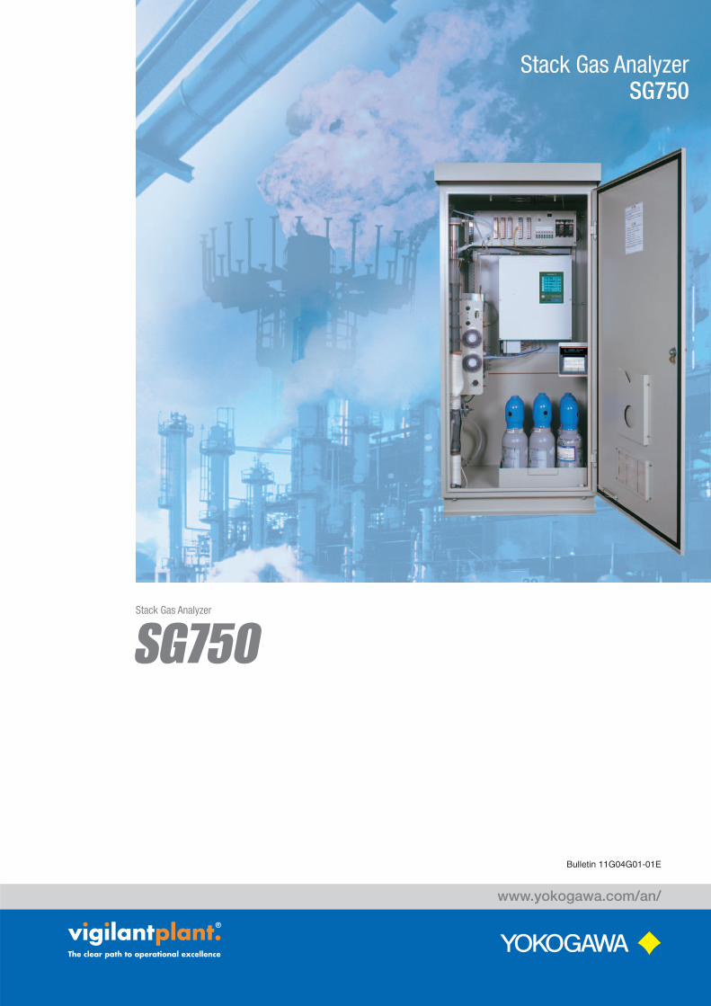
Measures NOX, SO2, CO and CO2 concentrations via an infrared method
The infrared dose absorbed by a sample cell is detected by the mass flow sensor.
When sample gas enters the measurement cell, the oxygen molecule is attracted to a field where there is considerable magnetic field strength, so that a force corresponding to the oxygen concentration is applied to the double sphere,where it is then converted into an electrical signal.
Detects the EMF (electromotive force) of an oxygen concentration cell generated on electrodes on the front and rear of the Zirconia element.
Paramagnetic Oxygen Analyzer (Built-in) Zirconia Oxygen Analyzer (External)
Heat ray temperature
No air flow status
Mass flow sensor(heat ray air flow velocity detecting element)
1mm
Detecting sensitivity( P)when there is an air flow from the left
Detecting sensitivity( P)when there is an air flow from the right
Sample gas outlet
Detector Interferencecompensation detector
<Mass flow sensor>Excellent noise resistance thanks to the low impedancesensor. The absence of moving parts makes the deviceresistant to vibration and semi-permanently usable.Converts the infrared absorbance into an electrical signal.High sensitivity allows a ratio within the range 1:25.
Sample cellSample gas inlet
Trimmer Reference cell
PP-
P
Distribution cell also serving as an interference filter
Infrared source
Motor
Rotarysector
SG750Continuously measures and monitors concentrations offlue gases generated from boilers or garbage incineratorsContinuously measures and monitors concentrations offlue gases generated from boilers or garbage incinerators
Dual Beam NDIR Stack Gas Analyzer
Principle
Power Plant
Cement Kiln
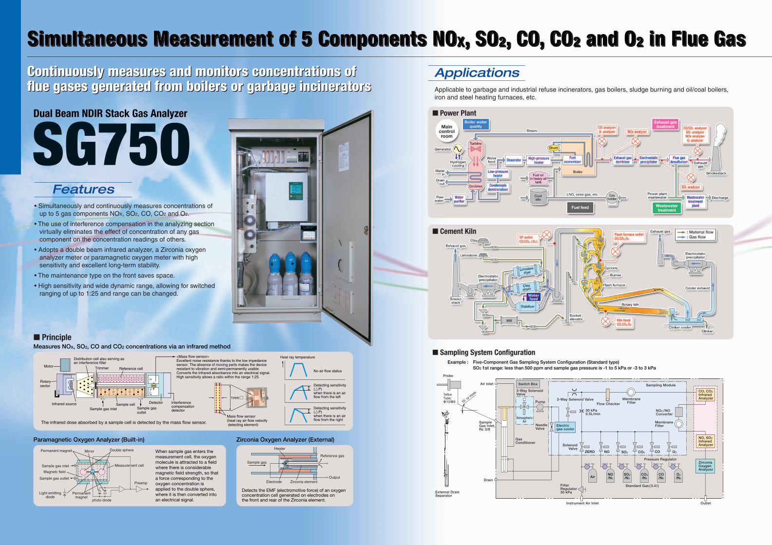
Sampling System Configuration
• Simultaneously and continuously measures concentrations of up to 5 gas components NOX, SO2, CO, CO2 and O2.
• The use of interference compensation in the analyzing section virtually eliminates the effect of concentration of any gas component on the concentration readings of others.
• Adopts a double beam infrared analyzer, a Zirconia oxygen analyzer meter or paramagnetic oxygen meter with high sensitivity and excellent long-term stability.
• The maintenance type on the front saves space.
• High sensitivity and wide dynamic range, allowing for switched ranging of up to 1:25 and range can be changed.
Simultaneous Measurement of 5 Components NOX, SO2, CO, CO2 and O2 in Flue GasSimultaneous Measurement of 5 Components NOX, SO2, CO, CO2 and O2 in Flue GasSimultaneous Measurement of 5 Components NOX, SO2, CO, CO2 and O2 in Flue Gas
Features
Applicable to garbage and industrial refuse incinerators, gas boilers, sludge burning and oil/coal boilers, iron and steel heating furnaces, etc.
Applications
Example : Five-Component Gas Sampling System Configuration (Standard type)SO2 1st range: less than 500 ppm and sample gas pressure is -1 to 5 kPa or -3 to 3 kPa
Probe
External DrainSeparator
SampleGas Inlet,Rc 3/8
Drain
Outlet
SolenoidValve
Pressure Regulator
Instrument Air Inlet
Air Inlet
Flow Checker
MembraneFilter
MembraneFilter
AtmosphericAir
Air
ZERO NO SO2 CO O2CO2
NO/N2
SO2/N2
CO2/N2
CO/N2
O2/N2
CO, CO2
InfraredAnalyzer
NO, SO2
InfraredAnalyzer
Switch Box Sampling Module
ZirconiaOxygenAnalyzer
FilterRegulator30 kPa
NO2 /NOConverter
GasConditioner
3-Way Solenoid Valve
NeedleValve
Pump
Standard Gas ( 3.4 l )
Electricgas cooler
2-Way Solenoid Valve
30 kPa0.5L/min

Subject to change without noticeAll Rights Reserved. Copyright © 2010, by Yokogawa Electric Corporation
Vig-PMK-G·NL-10E
YOKOGAWA ELECTRIC CORPORATION
World Headquarters9-32 Nakacho 2-chome, Musashino-shi,Tokyo 180-8750, JAPANTel: +81-422-52-6316 Fax: +81-422-52-6619http://www.yokogawa.com/an/
North AmericaYOKOGAWA CORPORATION OF AMERICAGeorgia, U.S.Ahttp://www.yokogawa.com/us/
South AmericaYOKOGAWA AMERICA DO SUL LTDA.BRAZILhttp://www.yokogawa.com.br/
EuropeYOKOGAWA EUROPE B.V.European HeadquartersTHE NETHERLANDShttp://www.yokogawa.com/eu/YOKOGAWA ELECTRIC CIS LTD. RUSSIAN FEDERATIONhttp://www.yokogawa.ru/
Middle EastYOKOGAWA MIDDLE EAST B.S.C.(C)http://www.yokogawa.com/bh/
SingaporeYOKOGAWA ENGINEERING ASIA PTE.LTD.http://www.yokogawa.com/sg/
KoreaYOKOGAWA ELECTRIC KOREA CO., LTD.http://www.yokogawa.com/kr/
ChinaYOKOGAWA CHINA CO., LTD.http://www.yokogawa.com/cn/YOKOGAWA SHANGHAI INSTRUMENTATION CO., LTD.http://www.ysi.com.cn/YOKOGAWA SICHUAN INSTRUMENT CO., LTD.http://www.cys.com.cn/
TaiwanYOKOGAWA TAIWAN CORPORATIONhttp://www.yokogawa.com.tw/
IndiaYOKOGAWA INDIA LTD.http://www.yokogawa.com/in/
AustraliaYOKOGAWA AUSTRALIA PTY. LTD.http://www.yokogawa.com/au/
Printed in Japan, 312(KP) [Ed : 01/b]
Represented by:
Measurement object
Measuring method
Measuring range
Output signal
Contact output
Contact input
Automatic calibration function
Power supply
Power consumption
Construction
Installation conditions
Weight
Sample gas conditions
Up to 4 components (NOX, SO2, CO2, CO) and O2 in flue gases
NOX, SO2, CO2, CO: Non-dispersive infrared methodO2: Zirconia or paramagnetic method
NOX: 0-50 ppm to 0-5000 ppmSO2: 0-100 ppm to 0-1000 ppmCO2: 0-10 vol% to 0-20 vol%CO: 0-50 ppm to 0-5000 ppmO2: 0-10/0-25 vol%Each is 2 range types. Maximum range ratio is 1:25, except O2 measurement.
4-20 mA DC or 0-1 V DC5 outputs for instantaneous values (NOX, SO2, CO2, CO, O2), 3 outputs for O2 correction instantaneous values (NOX, SO2, CO), 3 outputs for O2 correction average values (NOX, SO2, CO), 1 output for average O2 value, permissible load resistance: 550Ω max. (750Ω max. for isolated output)
(1) Each 1a contact (contact capacity 250V AC/2A, or 30V DC/3A)
•Each component range identification, analyzer failure, calibration failure, calibration status, maintenance status.
•CO peak count alarm(2) Each 1c contact (contact capacity 250 V AC/1A or
30 V DC/1A)•Each instantaneous value alarm (H/L/HL,configurable)•Analyzer power shutdown
Auto calibration start, average reset, range switching, output hold, remote pump off
Zero, span are auto calibrated (calibration cycle settable)•Interval range;1 to 99 hours (1 hour increments) or 1 to 40 days (1 day increments)
•Time of calibration gas flow: 60 to 599 seconds (1 second increments)
100/110/115/200/230 V AC ±15%, 50/60 Hz ±0.5 Hz
Approx. 600 VA (excluding probe and heating sample tube)
Outdoor/indoor stand-alone system, non-explosion proof, rainproof, single swing front door, standard plate thickness of 2.3 mm (both housing and door)
Avoid direct sunlight and vibrationAmbient temperature:
-5 to 40°C-15 to 40°C (cold district version: specify “/T1”)-10 to 40°C (cold district version: specify “/T2”)
Ambient humidity: 90%RH or less
Approx. 300 kg (without standard gases)
Temperature: 1400°C or lessDust: 500 mg/Nm3 or lessPressure: -1 to 5 kPa, -3 to 3 kPa, -5 to 1 kPaFlow rate: Approx. 2 L/min
Standard SpecificationsRepeatability
Linearity
Stability
90% response time
Warm-up time
± 0.5 % of FS
± 1.0 % of FS
Zero drift : ± 1% of FS/week ( ± 2% of FS/week for the range of 200 ppm or less)± 2% of FS/month for zirconia oxygen analyzers
Span drift : ± 2% of FS/week (± 2% of FS/month for zirconia oxygen analyzer)
(From the inlet of the system)Approx. 4 minutes for SO2
Approx. 2 minutes for others
Approx. 4 hrs. (after power on)
Characteristics
Note: Fluctuation in the operation period of 4 hours from the end of warm-up time is within ± 2% of FS.
External DimensionsUnit: mm
120
1380
700
580
Upper line(calibrationgas inlets)6-Rc 1/4
Air inletRc 1/4
4-Wiring Portsø 34 grommets(For outdoor type,waterproof glandsare required)
Left Side View
DrainRc 1/2
ExhaustRc 1/4
Vent hole
70 90
550
100
Instrument air inletRc 1/4, Rc 1/2
(43)
Sample gas inletRc 3/8
615
1800
(O
utdo
or T
ype)
800620
70
100
770
4-ø15 holesFor M12anchor boltsFront View
60
Tag plateNameplate
815 (Outdoor Type)
800 (Indoor Type)
1710
(In
door
Typ
e)
30˚