Embed Size (px)
Citation preview

AP- 2L1
STAGE 1 & 2 REPORTS
DATE: J3W %, 'XOOt

RICE Operating
Junction Box E-15 Remediation Project
RECEIVED JUN 0 8 2001
ENVIRONMENTAL BUREAU OIL CONSERVATION DIVISION
Whole Earth Environmental 19606 San Gabriel Houston, Tx. 77084 (800) 854-4358 www.wholeearthonIine.com

Site Profile
Location The spill area is located within Section 15, T22S, Range 37E southeast of Eunice, New Mexico on fee land owned by Messrs. Irvin Boyd and Robert Cueto. The primary land use is that of grazing cattle. Significant oilfield development is present within the area and several oil wells, storage tanks, flow lines and ancillary structures are present on both landholdings. A 7.5' map is enclosed within this section to define the location (Exhibits 1 &2).
The topography is unremarkable. There are no surface streams or catchments within one mile of the site.
Spill Discovery & Notification On March 29, 2000 a leak of produced brine water was discovered and verbally reported to the Hobbs office of the NMOCD. This notice was followed up the next day with a Form C-141 (Exhibit 3) describing the cause of the leak as due to a rusted sleeve.
Containment Rice Operating Company immediately recovered approximately 300 barrels of fluid and began excavation and disposal of the contaminated soils. The initial excavation and disposal effort resulted in approximately 2,000 cubic yards of contaminated being transported to the Sundance Parabo Facility. With the initial excavation at approximately 15' bgi, the site was contoured to insure that any potential contaminate migration would be to the center of the site.
Testing Protocol Soil and water sampling was conducted in accordance with the site investigation plan: PR-61, enclosed as Exhibit 4.

Soil Testing In an effort to determine the vertical and lateral extent of contaminant migration, Claiborne Harrison Corp. drilled a series of six boreholes on July 14, 2000. A site map describing the location of these test holes is provided as Exhibit 5. The test holes were sampled extensively to detennine the chloride concentrations within the remaining plume. The results of these tests are contained within Exhibit 6.
Water Testing On January 22,2001, Clairborn Harrison Corporation drilled and completed two water monitoring wells. The location of these wells is described within the attached survey, Exhibit 7). WW-1 was completed satisfactorily and sampled on January 23 in accordance with WEQP-28 and WEQP-77. WW-2 was successfully drilled, however the tight formation did not allow a sufficient volume of fluid to be pumped from the well bore to obtain meaningful test results.
Whole Earth Environmental was notified of the test results of WW-1 on January 25th and immediately notified Messrs. Price and Williams of the NMOCD telephonically that day and provided written notification and copies of the test results and associated chain of custody the next day (Exhibits 8-12).
Whole Earth Environmental re-sampled MW-2 on February 27, 2001. Mr. Buddy Hand of the Hobbs office ofthe NMOCD witnessed the re-sampling. The results of these analyses are provided in Exhibits 13-15.
Based on the results of the first two monitor well test results, two additional monitor wells were drilled, cased, and developed in early May. The two new monitor wells were sampled on May 23,2001. The test results indicate that an additional plume source may Ue up-gradient from the E-15 junction box leak (Exhibits 19,19A & 19B). Additional investigation will be conducted to determine the source of this plume.
Site Geology The boring logs from the six test holes and two monitoring wells (Exhibits 16A-H), reveal a red, sandy topsoil extending to a depth of approximately 5' bgi underlain by tan calichi to approximately 30' bgi atop a 40' dense sand layer. A 3' layer of indurated sandstone lies immediately above an 18' red bed clay layer.
Hydrology The U.S.G.S. survey maps (Exhibits 1 & 2) indicate a general decline in elevation to the southeast. The civil survey (Exhibit 7) shows the elevation of MW-1 to be 3,403.4' at the top of the cement pad. The distance to ground water from the top of the pad is 73.2'. The elevation of MW-2 is 3403.1' at the top of the cement. The distance to groundwater is 77'. The gradient between the two water depths is .00928 ft. / ft.

mmmm
^ r.i
Exhibit Index
1. U.S.G.S. topographical map
2. U.S.G.S. topographical map
3. N.M.O.C.D. Form C-141
4. Site Investigation Plan PR-61
5. Bore hole location schematic
6. Bore hole chloride concentrations
7. Basin Survey showing locations of monitor wells
8. January 26th, 2001 notification letter to Wayne Price
9. January 26th, 2001 notification letter to Chris Williams
10. Environmental Labs of Texas chain of custody document
11. Environmental Labs of Texas report of BTEX concentrations
12. Environmental Labs of Texas report of chloride concentrations
13. Environmental Labs of Texas chain of custody document
14. Environmental Labs of Texas report of BTEX concentrations
15. Environmental Labs of Texas report of chloride concentrations
16A. Well Report-Bore Hole # 1
16B. Well Report-Bore Hole # 2

16C. Well Report-Bore Hole # 3
16D. Well Report-Bore Hole # 4
16E. WeU Report-Bore Hole # 5
16F. Well Report-Bore Hole # 6
16G. WeU Report-Monitor WeU # 1
16H. Well Report-Monitor WeU # 2
161. Boring Log Monitor WeU # 3
16J. Boring Log Monitor WeU # 4
17. Water weU development procedure QP-28
18. Water weU sampling procedure QP-76(A)
19. Chain of Custody document for MW 3& 4
19A. Environmental Labs of Texas report of chloride concentrations
19B. Environmental Labs of Texas report of BTEX concentrations


P.O. Bat 1980, Hobbs, NM 88241-1980 Districts 811 South First, Artesia, NM 88210
M P̂JsOOORi 000 Rio Brazos, Aztec, NM 87410 District IV 2040 South Pacheco, Santa Fe, NM 87505
State ofNew Mexico Energy, Minerals & Natural Resources Department
OH. CONSERVATION DIVISION 2040 Sooth Pacheco Santa Fe, MM 87505
OPERATOR'S MONTHT.y BMP/TOT
Exhibit 3 nomicanon and corrective Action
Fonn C-141 Originated 2/13/97
Submit 2 copies to Appropriate District Office in accordance
with Rule 116 on hack Bde of form
OPE] I A T O R X Initial Report Final Report Name
Rice Operating Company Contact
John L. Moody Jr.
Address
122 West Taylor Hobbs, NM 88240 Telephone No.
505-393-9174 Facility Name
BJD.SWD Facility Type
PRODUCED WATER PIPELINE
Surface Owner Mineral Owner Lease Na
IRVIN BOYD & ROBERT CUETO •
LOCATION OF RELEASE Unit Letter Section Township Range Feet from the North/South line Feet from the East/West Line County E&D 15 T22S R37E LEA
NATURE OF RELEASE Type of Release Production Water
Volume of Release
TJNKOWN Volume Recovered
300BBLS •^Bjee of Release Oate and Hoar of Occurrence
1:00PM 3-29-00 Date and Hour of Discovery
SAME it as Immediate Notice Given?
| X |YES NO Not Required IfYES.ToWhom?
SLYVIA By Whom?
JOHN L. MOODY Date and Hour 3:55 3-29-00
Was a Watercourse Reached?
Q Yes gNo If YES, Volume Impacting the Watercourse.
If a Watercourse was Impacted, Describe Fully. (Attach Additional Sheets If Necessary)
N/A
Describe Cause of Problem and Remedial Action Taken. (Attach Additional Sheets If Necessary) STEEL DRESSER SLEEVE RUSTED OUT, TAKE DRESSER SLEEVE OUT AND REPLACE WITH JOINT OF PVC PIPE
Describe Area Affected and Cleanup Action Taken. (Attach Additional Sheets If Necessary) Area affected: 1512 SQUARE FEET IN UNIT LTR. "D". 10,450 SQUARE FEET IN UNIT LTR."E*\ IRVIN BOYD IS THE SURFACE OWNER IN UNTT LTR. "E" AND HE WANTS ALL IMPACTED SOIL DUG OUT AND REPLACED WITH CLEAN AND WE HAVE STARTED HAULING 3-30-00. WE WILL DO THE SAME FOR ROBERT CUETO IN UNIT LTR. "D"
I heielycerrify that the infonnarion given abc^g md /nr fife certain irima rmrificatmm mri pnfam cnmetine acting firnshflnw ffhfe* may WIlfrnF ptihlic health nrthe Bmiuiimt The acceptance of a C-141 report by the NMOCD marked aa "Final Report" does not relieve the or̂ ratoroftialdrry should rhcir operatic human health or tbe environment In addition, NMOCD acceptance of a C-141 report does net relieve the cperaorcfiespons
i Name: John L.Moody Jr. M / A ^ J f
OIL CONSERVATION piVISION
Approved by District Supervisor:
•" / /• " V Title: Regulatory Compliance Coordinator
/ Approval Date: Expiration Date:
Date3-30-00 Phone: 505-393-9174 A M i • r - i

U M
Exhibit 4 PR-61
Site Investigation Plan Rice Operating Company
Junction Box 15
1.0 Purpose This plan is to be used to determine the vertical extent of contamination adjacent to Rice Operating Company's Junction Box E-15.
2.0 Scope
This plan is site specific for the Rice Operating investigation project.
3.0 Preliminary Prior to any field operations, Whole Earth Environmental shall conduct the following activities: 3.1 Client Review
3.1.1 Whole Earth shall meet with cognizant personnel within Rice to review this protocol and make any requested modifications or alterations.
3.1.2 Changes to this protocol will be documented and submitted for final review by Client prior to the initiation of actual field work.
4.0 Safety 4.1 Prior to work on the site, Whole Earth shall obtain the location and phone numbers ofthe nearest emergency medical treatment facility. We will review all safety related issues with the appropriate Client personnel, sub-contractors and exchange phone numbers.
4.2 A tailgate safety meeting shall be held and documented each day. All subcontractors must attend and sign the daily log-in sheet.
4.3 Anyone allowed on to location must be wearing sleeved shirts, steel toed boots, and long pants. Each vehicle must be ©quipped with two way cornmimication capabilities.

PR-61 Page 2
4.4 Prior to any excavation, New Mexico One Call will be notified. The One Call notification number will bs included Vvithin the closure report. I f lines are discovered within the area to be excavated they shall be marked with pin flags on either side ofthe line at maximum five foot intervals.
5.0 Coring 5.1 A delineation hole will be cored at the southeast corner ofthe surface stain area. A log will be kept by the coring company outlining soil morphology.
6.0 Soil Sampling 6.1 Soil samples will be obtained in accordance with WEQP-77 at the ground surface and at each 10' depth interval.
7.0 Soil Analysis 7.1 The soil samples obtained under 6.1 of this plan will be transported to a laboratory and tested for the presence of DRO-GRO TPH, BTEX and chlorides.
8.0 Water Sampling 8.1 The coring rig will drill to a rninimum depth of 15' below the upper interface layer of the water table.
8.2 The well will be left uncased but developed by pumping fluid from the well bore until a minimum turbidity is found but a minimum of twenty gallons of fluid from the well bore shall be drawn.
8.3 All bailed fluids shall be collected by the coring company and disposed of at an approved disposal facility.
8.4 The open well bore shall be protected to insure that no foreign matter may enter the bore while a water analysis is conducted.
8.5 A water sample shall be collected in accordance with WEQP-76 and transported to a laboratory for the analysis of BTEX and chlorides.
9.0 Investigation Report 9.1 Whole Earth will provide an investigation report containing the following
minimum information:

PR-61 Page 2
• Photographs ofthe location ofthe test boring • Photographs ofthe entire spill area • Copies of this protocol and all testing procedures • Independent laboratory analyses and associated chains of custody • Driller's Log

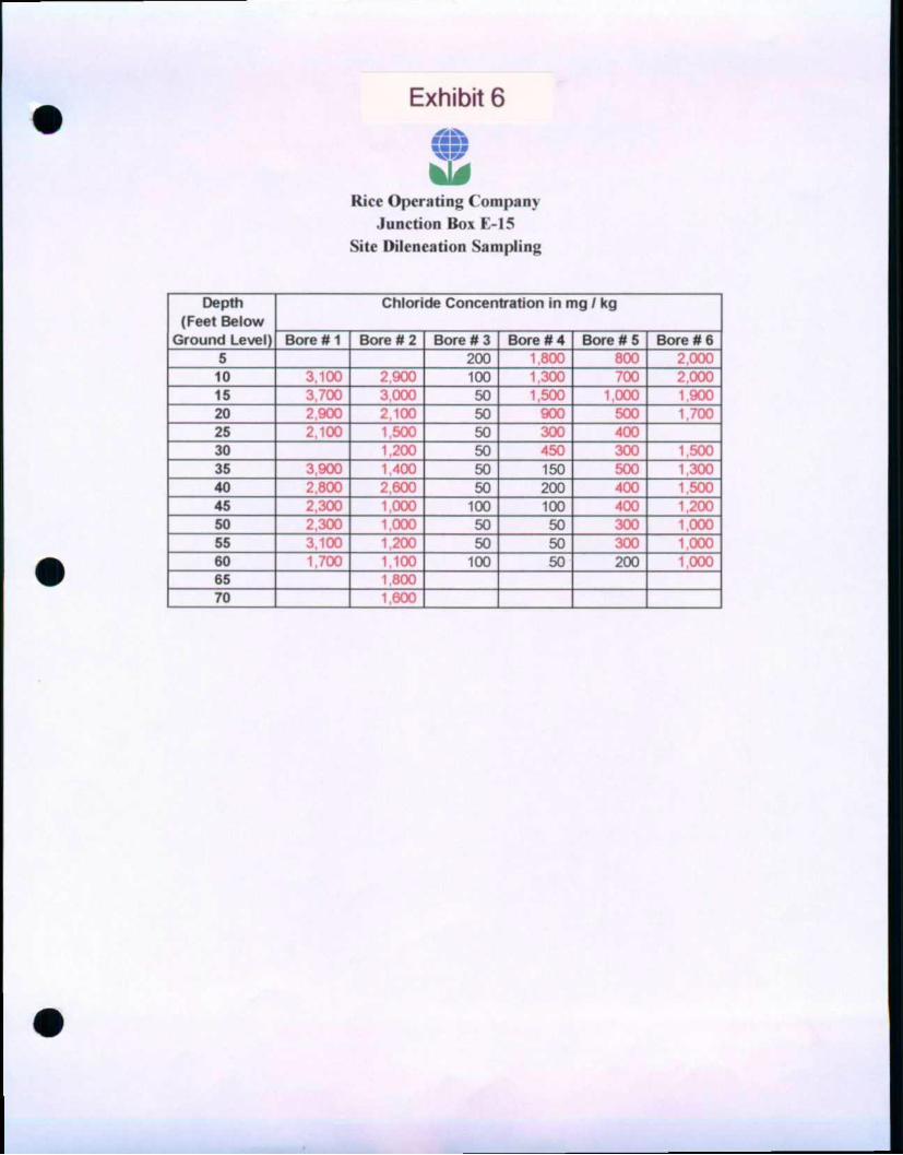
Exhibit 6 ran ww mm
mm mmi
Rice Operating Company Junction Box 115
Site Dileneation Sampling
Depth (Feet Below
Ground Level)
Chloride Concentration in mg / kg Depth (Feet Below
Ground Level) Bore n 1 Bore # 2 Bore # 3 Bore # 4 Bore #5 Bore U 6 5 200 • 80! 800 2,000
10 3,100 2,900 100 1,300 700 2,000 15 3,700 3,000 50 1,500 1,000 | BOO 20 2,900 2,100 50 900 500 1,700 25 2.100 1 500 50 300 400 30 1,200 50 450 300 1,500 35 3,900 1,400 50 150 500 1,300 40 2,800 2,600 50 200 400 1,500 45 2,300 1 000 100 100 400 1,200 50 2,300 i 000 50 50 300 1,000 55 3,100 1,200 50 50 300 1,000 60 1,700 1,100 100 50 200 ; i)«K i
65 1,800 70 1 600

SECTION 15, TOWNSHIP 22 SOUTH, RANGE 37 EAST, N.M.P.M., LEA COUNTY", —
Exhibit 7 NEW MEXICO.
FND R.R. FND SPK IN PVMNT N89S9'00'E (BASIS OF BEARINGS) 57tW£
WELL GRND ELEV.
PAD ELEV. NORTHING EASTING LA T1TUDE LONGITUDE
MW/7 3398.3' 3398.6' N509436.578 E904771.875 N32-23'42.0" W103V9'21.2"
MW #2 3398.4' 3398.9' N509096.706 E905055.281 N32'23'38.6" WJ03V9'77.9"
MW /3 3397.6' 3397.8' NS09842.177 E904419.441 N32'23'46.1" W103V9'25.2"
MW/4 3397.9' 3398.6' N508876.745 E905266.429 N32-23'36.4" W103V9'15.5"
ALL COORDINATES ARE BASED ON NMSPCE (NADB3)
I HEREBY CERTIFY THAT THIS PLAT JW5l<PR£PARE0~ FROM FIELD NOTES OF AN ACTUAL! "
1000 0 l-l M H H H 1=
1000 2000 FEET
5^ SURVEYS AS SPECIFIED -̂BY^miSASTATE.̂ f \ ° \ W
GARY L JOMES N.M. P.S. \ ^ O N 8 ? ^ ^ # / TEXAS P.L.S. ^ N ^ O Q a ^ f f l * ^ ^ ^
BASIN SURVEYS P.O. BOX 1786-HOBBS, NEW MEXICO
WHOLE EARTH ENVIROMENTAL, INC. 5^ SURVEYS AS SPECIFIED -̂BY^miSASTATE.̂ f \ ° \ W
GARY L JOMES N.M. P.S. \ ^ O N 8 ? ^ ^ # / TEXAS P.L.S. ^ N ^ O Q a ^ f f l * ^ ^ ^
BASIN SURVEYS P.O. BOX 1786-HOBBS, NEW MEXICO
REF: MONITOR WELLS BD SITE - Jet. Box E-15
5^ SURVEYS AS SPECIFIED -̂BY^miSASTATE.̂ f \ ° \ W
GARY L JOMES N.M. P.S. \ ^ O N 8 ? ^ ^ # / TEXAS P.L.S. ^ N ^ O Q a ^ f f l * ^ ^ ^
BASIN SURVEYS P.O. BOX 1786-HOBBS, NEW MEXICO
MONITOR WELLS LOCATED IN
SECTION 15, TOWNSHIP ZZ SOUTH, RANGE 37 EAST,
N.M.P.M., LEA COUNTY, NEW MEXICO. W.O. Number 1522 | Drawn By: K. GOAD
MONITOR WELLS LOCATED IN
SECTION 15, TOWNSHIP ZZ SOUTH, RANGE 37 EAST,
N.M.P.M., LEA COUNTY, NEW MEXICO.
Date: 05-30-2001 | Disk: KJG CD#3 - RC1522A.DWG Survey Date: 05-29-2001 Sheet 1 of 1 Sheets

Exhibit 8
January 26,2001 Mr. Wayne Price NMOCD Office 1220 South St. Francis Dr. Sante Fe, New Mexico 88505
Re. Notice of Groundwater Impact: UL D&E, Sec 15, T22S, R37E BD SWD System Operated by Rice Operating System
Dear Mr. Price.
On January 22nd Whole Earth Environmental, Jne. witnessed the drilling and completion of two water monitoring weUs situated adjacent to a spill area defined as UL D&E Sec 15, T22S, Range 37E, Junction Box E-15. A 7.5 minute map specifying the location is included within this transmittal.
On January 23rd Whole Earth Environmental, Inc. collected water samples from the two wells and transported them to Environmental Labs of Texas for the analysis of BTEX and chlorides. The enclosed analytical results indicate that the chloride concentrations within MW-1 exceed NMWQCC standards. The analytical results for MW-2 should not be considered reliable or accurate as we were unable to bail sufficient fluids from within the wellbore to develop the well.
These analytical results were received by Whole Earth Environmental, Inc. on the morning of January 25. Mr. Olson was notified of these results by e-mail that afternoon.
We are presently working to provide you and Chris Williams a Stage 2 Abatement Plan by March 31st, 2001.
Sincerely,
Mike Coffin President Whole Earth Environmental, Inc.
Cc: Carolyn Haynes / Rice Operating System
-^•(Enclosure: 7.5' map ELT Analysis Chain of Custody

Exhibit 9
January 26,2001 Mr. Chris Williams NMOCD Hobbs Office 1625 North French Drive Hobbs, New Mexico 88240
Re: Notice of Groundwater Impact: UL D&E, Sec 15, T22S, R37E BD SWD System Operated by Rice Operating System
Dear Mr. Williams:
On January 22nd Whole Earth Environmental, Inc. witnessed the drilling and completion of two water monitoring wells situated adjacent to a spill area defined as UL D&E Sec 15, T22S, Range 37E, Junction Box E-15. A 7.5 minute map specifying the location is included within this transmittal.
On January 23rd Whole Earth Environmental, Jne. collected water samples from the two weUs and transported them to Environmental Labs of Texas for the analysis of BTEX and chlorides. The enclosed analytical results indicate that the chloride concentrations within MW-1 exceed NMWQCC standards. The analytical results for MW-2 should not be considered reliable or accurate as we were unable to bail sufficient fluids from within the wellbore to develop the well.
These analytical results were received by Whole Earth Environmental, Inc. on the morning of January 25. You were notified of these results telephonicafly that afternoon. My efforts to reach you by e-mail at [email protected]/ were unsuccessful
We are presently working to provide you and Wayne Price a Stage 2 Abatement Plan by March 31st, 2001.
Sincerely,
Mike Griffin President Whole Earth Environmental, Inc.
Cc: Carolyn Haynes / Rice Operating System
Enclosure: 7.5' map ELT Analysis Chain of Custody

•
I 1 to
Q
8 to o o !
i
so
E
o ct
LU
O C
tn (0 x
o .Q CO
c5
es N.
n n to to •9 "?
= IS a
m tn m a> to
y c o S
» i l l eo
o I s
o 5"
ki
a E o u
v3
v
O Z. o-
o I—
a.
"3-
o
5
Si
- S i
tr
s
3* ( v /
5
o|npaips-34d) I V l H S n «
0E0S/aiZ08X3iS
S9|tlE|DA!UJ9S
se|RB|0A
as B H qd JO PO Eg Ov s v sp jaw
OUO/OH9WSl08Hdl
9001/9001XI H d i
0 3 / e V S / l O / S O l
8 5
(0
"O 2 TJ O >• e
O
c 3
"5 v
£ (0
:(AKoeds) js i f lo
l!0S
eEpms
( f loods )J9lflQ
BUON
"OS'H
HOEN
IOH
cONH
30|
SJ6UIEPJOQ j o Of j
pe|duiES e ^ Q
X"
\
\ \
f i l l ' i
f vo JS

Z N V I R O N M E N T A L
LAB OF , INC. "Don't Treat Your Soil Like Dirt!"
Sample Type: Water Sample Condition: Intact/ Iced/ HCI/ -1 deg. Project # : None Given Project Name: JB-15 Project Location: Eunice, N.M.
WHOLE EARTH ENVIRONMENTAL ATTN: MR. MIKE GRIFFIN 19606 SAN GABRIEL HOUSTON, TEXAS 77084 FAX: 281-646-8996
Exhibit 11 Sampling Date: 01/23/01 Receiving Date: 01/24/01 Analysis Date: 01/24/01
ELT# FIELD CODE BENZENE TOLUENE ETHYLBENZENE m,p-XYLENE o-XYLENE
mg/L mg/L mg/L mg/L mg/L
36787 36788
MW-1 MW-2
<0.001 <0.001
<0.001 <0.001
<0.001 <0.001
<0.001 <0.001
<0.001 <0.001
%IA %EA BLANK
104 93
<0.001
103 92
<0.001
105 95
<0.001
107 96
<0.001
108 97
<0.001
METHODS: EPA SW 846-8021B ,5030
Raland K. Turtle /-ZT-0/
Date

ENVIRONMENTAL
LAB OF , INC. "Don't Treat Your Soil Like Dirt!"
WHOLE EARTH ENVIRONMENTAL ATTN: MR. MIKE GRIFFIN 19606 SAN GABRIEL HOUSTON, TEXAS 77084 FAX: 281-646-8996
Sample Type: Water Sample Condition: Intact/ Iced/ -1 deg. C Project # : None Given Project Name: JB-15 Project Location: Eunice, N.M.
Exhibit 12 Sampling Date: 01/23/01 Receiving Date: 01/24/01 Analysis Date: 01/24/01
ELT# FIELD CODE Chloride
mfl/L
36787 36788
MW-1 MW-2
19675 780
QUALITY CONTROL 5140 TRUE VALUE 5000 % INSTRUMENT ACCURACY 103 BLANK <10
METHODS: EPA 325.3
fl d Raland K. Turtle Date


ENVIRONMENTAL
LABOFK^ , INC. "Don't Treat Your Soil Like Dirt!"
WHOLE EARTH ENVIRONMENTAL, INC. ATTN: MR. MIKE GRIFFIN 19606 SAN GABRIEL HOUSTON,TEXAS 77084 FAX: 281-646-8996
Sample Type: Water Sample Condition: Intact/ Iced/ HCI/ 3.5 deg. i Project # . E-15 Project Name: None Given Project Location: Eunice, N.M.
Exhibit 14
ELT# FIELD CODE BENZENE
mg/L TOLUENE
mg/L ETHYLBENZENE
mg/L
Sampling Date: Q2/27/01 Receiving Date: 02/28/01 Analysis Date: 02/28/01
m,p-XYLENE o-XYLENE mg/L mg/L
37796 MW-2 <0.001 <0.001 <0.001 <0.001 <0.001
%IA °/oEA BLANK
86 87
<0.001
93 88
•CO.001
96 91
<0.001
93 88
<0.001
96 91
<0.00l
METHODS: EPA SW 846-8021B ,5030
Raland K. Turtle '

ENVIRONMENTAL
LAB OF <J , INC. "Don't Treat Your Soil Like Dirt!"
Sample Type: Water Sample Condition: Intact/ Iced/ 3.5 deg. C Project # : E-15 Project Name: None Given Project Location: Eunice, N.M.
ELT# FIELD CODE
WHOLE EARTH ENVIRONMENTAL, INC. ATTN: MR. MIKE GRIFFIN 19606 SAN GABRIEL HOUSTON, TEXAS 77084 FAX: 281-646-8996
Exhibit 15 Sampling Date: 02/27/01 Receiving Date: 02/28/01 Analysis Date: 03/01/01
Chloride mg/L
37796 MW-2 886
QUALITY CONTROL 5052 TRUE VALUE 5000 % INSTRUMENT ACCURACY 101 BLANK <10
METHODS: EPA SW 846-9253
Raland K. Tuttle " Date

02/06/2001 15:16 FAX _004
Exhibit 16A Send anginal copy by certified mail to:
ATTENTION OWNER Conmemmlity PlMege Notice on rovers* Sitte Of Wall Omar's COP* (pink)
T D L R . P
State of Texas WELL REPORT
Ysxes Department or Licensing & Regulation
P.O. BOX 12157 Austin. TX 78711
512-461-7880
3) TYPE OF WORK (Chock): I «) PROPOSCD USE <CMc*r. 0 Montor B Environmental Soil BOftog ° Domestic
65 New Well • Deepening O industrial • irrigate*. • injection O Public Supply O De-watering • Testwel
• ReeondHioning B Plugging « PuW« Supply well. were plens submitted (0 the THRCC7
SB-1 n n . * ™ ™ ^ n t r a v e l P a r . u - 1 O O t h e r
II Gravel Packed give interval Irom ft to _ ft 0 5 Sand - Red
n n . * ™ ™ ^ n t r a v e l P a r . u - 1 O O t h e r
II Gravel Packed give interval Irom ft to _ ft
5 30 Caliche - Tan CASINO, BLANK PIPE. ANO WELL SCREEN OATA:
30 65 Sand - Red/Brown Dia.
New Or
used
Steel. Ptasbc. etc Pert.. Stoned, etc Screen M0.. it commercial
Sewn Gage Casing Screen
Dia. New
Or
used
Steel. Ptasbc. etc Pert.. Stoned, etc Screen M0.. it commercial From To
Gage Casing Screen
Dia. New
Or
used
Steel. Ptasbc. etc Pert.. Stoned, etc Screen M0.. it commercial From To
Gage Casing Screen
1) OWNER Rice Operating Co. (Name)
ADDRESS 122 W. Tavtor Hobbs NM
ADDRESS OF WELL'S LOCATION.
County Lea 3 S . on Hwy. 207
(street or RFD)
Long.
Eunice
(City)
NM 88231
(Stale)
Lat. _
GRID*
88240 (Zip)
(Street RFD or otner) (City) (Stata)
8) WELL LOG
DSteOnlfingr.
Started _
Completed.
7/14/00 7/14/00
• Ye» • No
DIAMETER O f HOLE
Dia.. (in.) From (f t )
Surface
TO(IL)
65
From f f i ) To ( f t ) Description and color of tarnation material
(Use reverse *<de of Wai) Cwrwrs copy. If necessory}
13) Well plugged within 4B hours
Casino left in wen.
From no JoJ2L
CemgnVbentomte placed In well:
From (H)
Sacks used:
14) TYPE PUMP:
• TurDlrte C j e t • Submersible • Cylinder
• Other
Depth to pump bowls. Cylinder, jet, e tc , 15) WELL TESTS:
Type teal c Pump
Yield _ _ _ _ _ gpm with
• Baoer • Jetted • Estimated
It, drawdown after hrs
16) WATER QUALITY:
Old you Knowingly penetrate any strata which contained undesirable constituents?
D Yes IS No tf yes. submit "REPORT OF UNDESIRABLE WATER"
Tvne of water-? F f e S h Depth o l strata N / A
Was Chemical analyses made? • Yes _ NO
7) DRILLING METHOD (Check):
B Air Rotary D Mud Rotary
O Air Hammer O Cable Tool
n other
• Driven
• Bored • jetteo
5)
8) Borehole Complet ion (Check): Q Open Hole O Stratghl Wai!
»> CEMENTING DATA
Cemented from Bentonite from 0
f l t o
ft to 65 tv NO. o l sacks used .
No of sacks used 13
Method used Chios cemented t>y Harrison & Cooper. Inc. Distance lo septic system field Ines or ether concer (rated contamination
Method of verification of above distance
tD) SURFACE COMPLETION
• Specified Surface Slab Installed
• Specified Steel Sleeve Installed
D Pffiess Adapter Used
• Approved Alternative Procedure Used
11) WATER LEVEL
Static level W A
Artesian Flow
ft. below land surface
gpm,
Dale 7/14/00 Date
12) PACKERS: Depth
I certify mat I drilled this well (or the wen was armed under my direct supervision) and that each and aB of the statements herein are true and correct I understand lhat failurt to complete items 1 thru 16 win result In the log(s) being returned for completion and reBubmrttat.
COMPANY NAME Claiborr>6 Harrison
ADDRESS 7202 66' (Trps rx Pr-i l
166 St-A
WELL DRILLER S LICENSE NO W D - 1 2 7 1 _
Lubbock TX 79407 (Cny) | S o _ ) t * P )
ri«»n,,«aw.itonii--i (SignM)
[f lgnlHorpn nrjltof T r a i i - t l
Plassc 3Uscn otocuir. log. cn»mi_» ansyia, ma OBW pwtlnant mfo—alion, it mtHt/X*
TDLR FORM D01WWD (4/88) Copies M TDLR. DRILLER, ami WELL OWNER Form provided by Forms On-A-Disk, Inc. Dallas, Texas • (214) J40-9428

02/06/2001 15:16 FAX 12)005
Exhibit 16B
•
^rH>oflnin-lcopybyceitme<Jmailto: TDLR, P.O. ""ATTENTION OWNER: CtanWenfisftfy
Prtvl/ege Nolice on reverse side 0/ Wa« Owner's copy (pir*)
State of Texas WELL REPORT
Texas Department of Licensing & Regulalion
P.O. Box 121 ST Austin, TX 78711
512-463-7880
3) TYPE OF WORK (Check):
B New Well C Deepening
O Reconditioning — Plugging
6) WELL LOG:
Dale Drilling
Slatted
Compleled ,
From (ft ) To(ft-)
SB-2 • Urtderraamed O Gravel Packed Q
If Gravel Packed give Nerval from
Other
0 S Sand-Red
• Urtderraamed O Gravel Packed Q
If Gravel Packed give Nerval from ft. to fl
5 30 Caliche - Tan CASING. BLANK PIPE, AND WBLL SCREEN 1 JATA:
30 70 Sand - Red/Brown Da. (inj
New
or Used
Steel. Plastic, ere
Pert.. Slotted, etc
Screen Mfg.. il commercial
SeWn Gage Casting
Screen Da. (inj
New
or Used
Steel. Plastic, ere
Pert.. Slotted, etc
Screen Mfg.. il commercial From To
Gage Casting
Screen Da. (inj
New
or Used
Steel. Plastic, ere
Pert.. Slotted, etc
Screen Mfg.. il commercial From To
Gage Casting
Screen
i i OWNER Rice Operatino Co. (Name)
2) ADDRESS OF WELL'S LOCATION.
Coun ty L e a 3 S - ° f f > D W y - 2 0 7
ADDRESS 122 W. Taylor Hobbs NM 8B240 (Street or RFD)
tons Eunice
(City)
NM 88231
(State)
U l .
G R I D *
(Zip)
(State) (Bp)
7/14/00 7/14/00
(Street. RFO or amer) (City)
4) PROPOSED USE (Check): D Monitor B Environmental So* Boring O Domestic
D industrial a irrigation • Injection • PuBfle Supply D De-watering • Testweil
U Putrtc Supply wed, were plans submitted to the TNRCC? D Yes • No
DIAMETER OF HOL—
Dia. (in.) From(h\)
Surface
To (ft.)
70
Description and co~r of formation material
7) DRILLING METHOD (Check): O Driven
- Air Rotary D Mud Rotary O Bored
• Air Hammer Q Cable Tool • Jettec
• Other
S)
B) Borehole Complet ion (Check): O Open Hole O Straight Wail
(Use reverse side of WeV Owners copy, rf necessary)
13) WHI ptuggea within 46 hours
Casing left in well.
From (ft) J_i2L
Cement/bentonrte placed io weB
From m To TO
Sacks used:
14) TYPE PUMP;
• Turbine — jet Q Submersible • Cylinder
• Other
Depth to pump bowls, cylinder, iet. d c . . .
15) WELL TESTS:
Type test' D Pump
Yield: gpm with
• Bailer O jet ted
fl. drawdown after
• Estimated
hrs
16) WATER QUALITY:
Did you knowingly penetrate any strata vhicn contained undesirable constituents?
• Yes » No tl yes, submit "REPORT OF UNDESIRABLE WATER*
Tvoe of water? F r e S h Depth of strata N/A
Was chemical analysis made? D Yes 8 No
9) CEMENTING DATA
Cemented trom
Bentonite from 0 ft. to
ft to 7 0
ft.
ft.
No o' sacks used .
NO. Ol sacks used . 14
Chips Method used
Cemented by Harrison & Cooper. Inc. Distance to septic system field lines or olher concentrated contamination ft
Method Of verification of above distance _ _ _ _ _ _ _ _ _ _ _ _ _ _ _ _ _ _ _ _ _ _ _ _ _ _ _
10) SURFACE COMPLETION
• Specified Surface Slab instated
• Specified Steel Sleeve Installed
• Pities* Adapter Used
— Approved Alternative Procedure Used
11) WATER LEVEL
Static level
Artesian Flow
N/A fv be l jw land surface
gpm.
Dele 7/14/00 Date
12) PACKERS: Type Depth
I certify that) drilled this well (or the well waa drilled under my direct supervision) and that each and all ot the statements herein are true and correa. I understand tnat failure <o complete items 1 thru 1 s will remit in the log(s) bemg returned for completion and resubmrttai
COMPANY MAMF Claiborne Harrison
AOORESS 7202 66LhSt.
{Signed)
(TvpaerPrini)
(Si aet g{_FO)
WELL DRILLER S LICENSE NO W D - 1 2 7 1
Lubbock I C w
UL 79407 (State)
(Signed) (RHiiiarea Dn tor "rai l- l i t
Plena s i x t i etecuic loo. cftemicai analysis, and other pertinent inti—aiion. it avaiiawj.
TDLR FORM 001WWD (4f9B) Copies to TDLR, ORfU-R and WELL OWNER Form provided Dy Forms On-A-Oisk, Inc. Dallas. Texas • (Z14) 340-9429

02/06/2001 15:17 FAX ©006
Exhibit 16C I ATTI 1 Pnvi)
ofW
S e n d ong ina l copy by cert i f ied mai l tol
ATTENTION OWNER: ConHdanUalny Privilege Notica on reverse side of WaU Owner's copy fjsvity
TDLR. P.O.
State of Texas WELL REPORT
Texas Department of Licensing & Regulation
P.O Box 1215? AUStH. TX 78711
512-4B3-79B0
1) OWNER Rice Operating Co. ADDRESS 122 W. Taylor, Hobbs NM 88240
(Name)
2) ADDRESS OF WELL'S LOCATION:
County Lea 3 S. on Hwy. 207
(Street or RFD)
Long .
E u n i c e
(City)
NM 88231
(Slate)
Lat _
GRID*
(Zip)
(Street RFD or other) (eny) (zip)
3JTYPEOFWORK -Cheek):
IS New Well O Deepening
O Recorvlrtioning — Plugging
6) WELL LOO: Date Drilling:
Started
Completed.
7/14/QQ 7/14/00
4) PROPOSED USE (Check) O Monitor 8 Environmental So* Boring D Domestic
_ industrial D Irrigation - iniection D Pubhc Supply a De-watermg O TestweU
If Public Supply wet , wen? plans submrBed to the TNRCC? 0 Y e B ° N o
DIAMETER O f HOLE
Dia. (in.) From (tt.)
Surface
To ( f t )
60
From (ft.) To (ft.) Description and color of formation material
SB 3 Sand - Red
30 Caliche - Tan 30 60 Sand - Red/Brown
/Use reverse side of Well Cwnor s copy. It necessary)
13) Wett plugged wfcNn 4s hou-a
Casing left In well
From (<Q To(h)
Cement/beraonne placed in wen.
From (W) JI-JSL
14) TYPE PUMP:
D Turbme 3 Jet • Submersible O Cylinder
O other
Sacks used:
Depth to pump bowls, cylinder, jet, etc..
15) WELL TESTS:
Type test O p u m o
Ytetd: gpm with
• Belter O jet ted • Estimated
ft. drawdown after hrs
16) WATER QUALITY:
Did you knowingly penetrate any strata whish contained undesirable eonstrtuenls?
• Yes _ No ff yes. submit "REPORT OF UNDESIRABLE WATER'
Type of water? F r e s h Depth Of strata N / A
Was chemical analysis made? D Yes - No
7) DRILLING METHOD (Cheek).
- An Rotary • Mud Rotary
D Air Hammer O Cable Tool
D other
O Driven
O Bored
D Jetted
5)
ff
8) Borehole Complet ion (Check): • Open Hole
• unoerreamed o Gravel Pac<ed D ottier
If Gravel Packed give interval from ft to
• Straight Wall
CASINO, BLANK PIPE, ANO WELL SCREEN DATA;
Dia.
_ _ or
Used
Steel, P—stic. etc
perf., Slotted, elc
Screen Mfg.. if commercial.
Setting (ft.j_
From TO
Gage
Casting
Screen
8) CEMENTING DATA
Cemented from Bentonite trom 0
ft to
ft. to 60 ft.
n No of sacks used_
No. of sacks used 12
Chips Harrteon & Cooper. Inc.
Method used
Cemented by
Distance lo septic system field lines or ether concentralea contamination .
Method o l verflicaUon of above distance
10) SURFACE COMPLETION
• Specifisd Surface Slab installed
• Specified Steel Sleeve Installeo
o Pitiess Adapter used
O Approved AltemativB Procedure Used
11) WATER LEVEL
Static level
Artesian Flow
N/A . ft below Isnd surface
UPm
Dare 7 / 1 4 / 0 0
Date
12) PACKERS: Pepin
I certify that I drilled M s well (Of the we* was drilled under my Used supervision) and that each and B« of the statements herein are true and correct I understand tnat taiturt to compter.* ttems l mru 16 will resuh in ths ag<s)Beir^ returned fwcomp le l lw
COMPANY NAME Clalbome Harrison
ADDRESS 7202 66mSV (T(oaorPr/ni)
(Signed)
WELL DRILLER'S LICENSE NO, W - t - 1 2 7 1
Lubbock TX (City)
(Signer!)
(Stata)
(Wmaacnd Orih, Tr»-—> "
79407 (2rp)
Prassa amen stearic log. cncmic— analy*;*, ana other perinem BV_—tan, if mailem.
TDLR FORM 001WWD (4/9B) Copies to TOLR, DRILLER amS WBLL OWNER Form provided by Forms On-A-Disk. Inc. Danes. Texas • (214) 340.942s

02/06/2001 15:17 FAX @007
Send otiflinal coOv by certified mail to. TDLR, P.C • ATTENTION OVVMTR CtxiMmtietXy
PnVrtepe Notice on r a w s * Side of WaU Owners copy (piPK)
Exhibit 16D
Stats of Texas WELL REPORT
Texas Department of Licensing & Regulation
P O Box 12157 AU3tjn,TX7B711
512-463-7860
1) ™-IFB Rice Operatino Co. (Namo)
2) ADDRESS OF WLLL S LOCATION;
county Lea 3 S. on Hwy. 207
ADDRESS 122 W. Tavlor (Street Of RFO)
Long .
Hobbs MM 88240 (City)
Eunice NM 88231
(Stale)
Lat. _
G R I D *
(Zip)
(Street. RFO or other) (City) (State) (Zrp)
3) TYPE OF WORK (Check):
B New WeV n Deepening
• Reconditioning B Plugging
s ; WELL LOG .
Date Drilling
Started
Completer!.
7/14/00 7/14/00
<) P R O P O S E D USE (Check): • Monitor B Environmental Soil Boring O Domestic
• Industrial • Irrigation • Injection D Public Supply O D e W e r m g CJ TeslweH
D Y e s D N O U Public Supply wed, were pans submitted 10 Bie TNRCC?
DIAMETER OF HOLE
DM.. (In.) From (ft.)
Surface
To ( f t )
60
From (ft.) To (f t ) Description end color or formation material
7) DRILLING METHOD (Cheek):
8 Air Rotary • Mud Rotary
O Air Hammer D Cable Tool
O other
• Driven
a Bored
• Jettea
5)
SEM Sand - Red
30 Caliche - Tan 30 60 Sand - Red/Brown
(Use reverse sloe of Well Owner's copy, if necessary)
13) Wetl p tu jged within 4« nours
Casing reft In wed
From (ft) T o _ _
Cemeni/benftyiite placed in wttM
Ffpm (ft)
14) TYPE PUMP:
3 Turbine O Jet O Submersible • Cylinder
D Other
Sacks used:
Depth to pump oowts, cylinder, jet, e tc ,
15) WELL TESTS:
Type test: D Pump
Yield: gpm wtth
• Bailer • Jetted
ft. drawdown alter
O Estimated
B) BorehOK Complet ion (Check): • Open Hole
• Linden-earned • Gravel P»c<ed a other
If Gravoi Packed give interval from
• siratghtwaii
ft to
CASINC, BLANK PIPE. AND WELL SCREEN DATA:
Dia
New
or
Used
Steel, Plastic, ale Pert., Slotted, etc Screen Mtg., if commercial
Setting (ft.)
From To
Gage Casting
Screen
9) CEMENTING OATA
Cemented from ft. to
Bentonee from 0 f l W 6 0
No of sacks used
No ot sacks used 12
Method used C h l P S
cememedby Harrison & Cooper. Inc. Distance lo septic system field fines or ether concertrated contamination
Method 0 l verification of above distance
10) SURFACE COMPLETION
• Specified Surface Slab Instated
• Specified Steel Sleeve Installed
• Pidess Adapter Used
• Approved Alternative Procedure Used
16) WATER QUALITY:
Did you knowingly penetrate any strata which contained undesirable constituents?
• Yes 81 No 't yes. suOmll"REPORT OF UNDESIRABLE WATER"
Type of water? F r e s h Deptn of strata N/A
Was chemical analysis made ' • Yes B No
n f s 11) WATER LEVEL
Static level N/A Artesian Flow
. ft. below Isnd surface
gpm.
Oa te 7 / 1 4 / 0 0
Date
12) PACKERS; peptn
t certify that I drilled t h * well (or the we* was drilled under my direct supervision) and that each and a* o l the statements herein are true end correct I understand that '8ltur« to complete items 1 thtu 16 win result in tht lcrg(s) being returned for completion end reaubmittal
COMPANY NAME Claiborne Harrison
ADDRESS 7202 6611* Sj (Type or Prim)
(Signed)
WELL DRILLER S LICENSE NO W D - 1 2 7 1
Lubbock TX 79407 (St-SetorRFD) (City) (Slale)
i i ^ r t i i M i i v a v i (Sienod)
HHMMWMI Onilar TrainMt
Please attsoi electric log, cwireeai anatyaa, am eater ponneru Wbrmaiiori. il available
TDLR FORM 001WWD (4/88) Copies to TDLR. DRILLER, and WELL OWNER Form provided by Forms 0n-A4>tsk, Inc. Dallas. Texas • (214) 340-9429

02/06/2001 15.17 FAX f_008
Send or ig ina l copy by cert i f ied maM to : T D L R . P.O
Exhibit 16E ATTENTION OWNER: CcmMenbaUty PrMege Notice on reverse side of Weff Owner's copy (pink)
State of Texas WELL REPORT
OWNER Rice Operating Co. (Name)
2) ADDRESS OF WELL'S LOCATION;
County Lea
ADDRESS 122 W. Taylor
3 S . on Hwy. 207 (Street RFD or other)
(Stfeet or RFD)
Long.
Eunice
Hobbs
Texas Department of Licensing & Regulation
P.O Box 12t57 Austin, TX 78711
51Z-493-7&80
88240 (Cty)
WM (State) (Zip)
NM (City) (State)
88231 (ZIP)
U t .
G R I D *
3) TYPE OF WORK (Check):
8 Mew Well O Deepening
O Recortdrtlorvng J3 Plugging
S) WELL LOO:
Dele Drrtnng;
Started
Completed.
7/14/00 7/14/00
4) PROPOSED USE (Check). • Monlkx — Environmental Soil Boring • D o m e s t i c
a industrial • Irrigation • Injection O Pubsc Supply 0 De-watering D TestweH
l l Public Supply we». were plans submined to »>e TNRCC? O Yes • No O Yes
DIAMETER OF HOLE
Dia ( in )
6
From ( f t )
Surface
To ( f t )
60
From (ft ) To (f t ) Oescnpbcm and color of formation materiel
SB-5 Sand - Red
30 Caliche - Tan
7) DRILLING METHOO (Check) '
B An Rotary a Mud Rotary
D Air Hammer • Cable Too)
• Otner
• Driven
• Bored
O Jetted
5 )
I ) Borehole Complet ion (Check): • Open Mote • Straight Wall
• Underreamed • Gravel Pac<ed Q Other
If Gravel Packed give Interval from ft. to
CASING. BLANK PIPE. AND WELL SCREEN DATA:
30 60 Sand - Red/Brown Dia (in.)
New or
Used
Steel. PlaSVC, etc Peri.. Slotted, etc Screen Mfg.. 1 commercial
Setfjri art.) Gage Casting Screen
Dia (in.)
New or
Used
Steel. PlaSVC, etc Peri.. Slotted, etc Screen Mfg.. 1 commercial From TO
Gage Casting Screen
Dia (in.)
New or
Used
Steel. PlaSVC, etc Peri.. Slotted, etc Screen Mfg.. 1 commercial From TO
Gage Casting Screen
(Use reverse svde of Weil Comers copy, if necessary)
13) Wes plugged within 4S hou •»
9) CEMENTING DATA
Cemented from f t lo
Bentonite from 0 ft IO 60 rt.
ft.
No. of sacks used No of sacks used 12
Casing left in well:
From ffl) To (ft) CementfbentonrtB placed w wee.
From (ft) T«»W
14) TYPE PUMP:
• Turbine • Jet • Submersible • Cylinder
• Other
Seeks used:
Method used C h t P S
Cemented by Harrison 8> Cooper. Inc. Distance to septic system field lines or ether concentrated contamination
Method ol venflearjon of above distance
Depth to pump bowls, cylinder, je t etc..
IS) WELL TESTS:
Type lest O Pump
Yield gpm with
1 t ) WATER QUALITY
• Bailer Q Jetteo • Estimated
_ _ _ _ _ fl drawdown ater _ _ _ _ _ _ _ _ _ hrs
noo ot verification c« BDOVB C
10) SURFACE COMPLETION
• Specified surface Slab Ins—Sea
• Specioaa Steel Sleeve k i i t iUed
• Pidess Adapter Used
D Approved Alternative Procedure Used T C D I C U E !
Ord you knowingly penetrate any strata win Hi contained undesirable constituents?
D Yes B No If yes, submit 'REPORT O f UNDESIRABLE WATER*
Type o!water? Fresh
Was chemical analysts made?
11) WATER LEVEL
Static level N / A
Artesian Flow
. ft below land surface
gpm.
Date 7 / 1 4 / 0 0
Date
Depth of strata N / A
• Yes B N O
12) PACKERS: Depth
1 certify that I dnBed mis we» (or the wet) was ruffled under my direct Supervision) and tnat each end aB of me statements herein are true end correct / understand inat W u n to complete items t thru 16 wtU result tn the kxj(s) being returned for rxrnptetion and resubmUtal. ^
COMPANY NAME Claiborne Harrison
ADDRESS 7202 66*"
(Signed)
(Type or Pnm)
tS t rMI or R f f j r j
. W E U DRILLER S U C E N S E NO W D - 1 2 7 1
Lubbock TX 79407 iMy) ISwte) |Z»>
' " " imnit f t i f t l l (Sign-id)
Piscie attacn trtacoic tup. crtc(~_t enairata, ancoetorponWwnr Jrvornwnon. JMBMHO
TDLR FORM O01WWD (4798) Copras » TOLA?. ORILLSR. ami WELL OWNER Form provided by Forma On-A-Diak. Inc. Dallas. Texas • (214) 340 9429

02/06/2001 15:18 FAX @009
Send original copy by certified mail to: ATTENTION OWNER: Contoanbtttty PrMeoe Notice on reverse siaa of Well Owner's cnpy ((rink)
T D L R , P.O. B o :
Exhibit 16F
State of Texas W E L L R E P O R T
Tsxas Oepartrnefw of l icensing & Regulation
P.O BOX 121S7 Austin. TX 78711
512-463-7880
I I OWNER Rice Operating Co. (Name)
2) ADDRESS OF WELL'S LOCATION:
ADDRESS 122 VV. Taylor Hobbs NM 88240
County Lea 3 S. on Hwy- 207
(Street or RFO)
Long .
Eunice
(City)
NM 88231
(Slate)
Lat. _
GRID*
Kip)
(Stats) (ap) (Street, RFD or otner) (Oty) 4) PROPOSED USE (Check)- D Monitor B Emitrirtrnentat Soil Boring a Domestic
O industrial O Irrigation • tr^ectton O Public Supply O Oe-watenna • TesbvWI
11 Public Supply well, were parts submitted to thaTHRCC? • Yes • No
J) TYPE OF WORK (Check):
B New Wen • Deepening
• Reconrjiborttnq 8 Plugging
«) WELL LOG:
Date OrrUng
sarteo 7 / 1 4 / 0 0
DIAMETER OF MOLE «) WELL LOG:
Date OrrUng
sarteo 7 / 1 4 / 0 0
Dra. (In.) From (ft ) To(IL)
«) WELL LOG:
Date OrrUng
sarteo 7 / 1 4 / 0 0 6 Surface 60 ComDleteO 7 / 1 4 / 0 0
7) DRILLING
B Air Rotary
• Air Hammer
• Other
METHOD (Check):
• Mud Rotary
• Cable Tool
D Driven
• Bored • Jetteo
5>
I* From (If.) To ( f t ) DasciiBrton and color of formation material O OpenHole • Siratght Wan
SB-6 • Llnderreamed • Gravel Pae<ed a
If Gravel Packed give interval from
Olher
0 5 Sand - Red • Llnderreamed • Gravel Pae<ed a
If Gravel Packed give interval from it-to n.
5 30 Caliche - Tan CASMG. BLANK PIPE, AMD WELL SCREEN DATA:
30 60 Sand • Red/Brown
Dia.
(fn.)
New
or
Used
Steel. Plastic, etc Pert.. Slotted, etc Screen Mfg.. if commercial
Settinq (ft.) Gage Casting Screen
Dia.
(fn.)
New
or
Used
Steel. Plastic, etc Pert.. Slotted, etc Screen Mfg.. if commercial From To
Gage Casting Screen
Dia.
(fn.)
New
or
Used
Steel. Plastic, etc Pert.. Slotted, etc Screen Mfg.. if commercial From To
Gage Casting Screen
(Use reverse side of Wen Cmar's copy. It necessary)
13) Wad p tuggw watwi * a boms
Casing left m welt Cement/bentortlie Macedinwen: Sacks used:
From (ft) TpjBJ From (ft) To (ft)
9) CEMENTING DATA
Cemented from
Bentonite from 0
B.lo ,
f t to 60 fL
ft
No. of sacks u s e d .
No. of sacks used 12
14) TYPE PUMP:
O Turbine Q Jet • Submetaibte • Cylinder
O Other
Chips Harrison 8i Cooper. Inc.
Death io pump bowls, cylinder, jet, e t c , .
15) WELL TESTS.
Type test-
Yield:
• Pump
gpm with
C Bailer
1«) WATER QUALITY:
Did you knowingly penetrate any strata amen con-uned undesirable conslltuenta?
O Yes ta No II yes. SUBRUI "REPORT OF UNDESIRABLE WATER"
Type of water? F f e s h Depth of straia N / A
Was chemical analysis made? O Yes a No
• Jetted • Estimated
S. drawdown after
Method used
Cemented by
Distance lo septic system field lines or ether concentrated ajntamvtetian
Method of verification o l above distance 10) SURFACE COMPLETION " "
• Speoiried Surfecs Stab Inslatled
• Speafied Sted Sleeve installed
• Prtlsss Adapter Used
• Approved Alternative Procedure Used
h ~ 11) WATER LEVEL
Static level
Artesian Flow
N/A ft. below land surface
9Phi-
Date 7/14/00 Date
12) PACKERS: Type Depth
' c ^ > r S * ! * ^ ^ t T l ̂ £ ! , ^ J ^ ^ ' ^ ? i ? ^ f ^ ' S ! l i and that each and alt ot me statements herein are true and correct I underslanfl mat failun complete itemE 1 thru 16 wiH result m the tog(5) b e m returned for comolerJon and resubmrtlHt tog(5) being returned for compleoon a m resuWnrttHt
COMPANY NAME Claiborne Harrison WELL DRILLERS LICENSE NO, WD-1271 (Type ci Pm»!
ADDRESS 7202 66" S t Lubbock
\ S It Irm^-M — _ • nn—n
TX 79407 (Cityl (SUrtv) (ZIC)
ftiwr^YmBniry) (5tr~W)
(HanfaMfridDriliefTfjr—n
Ptaasa attach BiActrit tog. cnomical errafyits. ami otrtar pertinent (nrijrmotkm,./ avstiebt^
TDLR FORM 091WWD (4790) Copies IO TDLR. DRILLER, and WELL OWNS* Form provided by Fo rm* On-A-Disk, inc. Dallas. Texas - (214) 340-9429

02/06/2001 15:15 FAX @002
Exhibit 16G nat copy by certified mail to TDLR. P .Q-
ATTENTION OWNER: ConfidtnUaltTy PrMega Notice on —verse side of Weff Owner's COW Ipmkj
State of Texas
WELL REPORT
Tswra Department ot Licaoslr Regulation
P O. Box 1215? AJSU1.TX7B711
51Z-463-7B80
3)TYP£OFWORK (Check):
B New we l l D Deepening
O Reconolibning • Plugging
MW-1 0 Underrearned & Gravel ""acted •
If Crawl Pecked give interval from 61
outer 16/30 Filter Sand
0 5 Sand - Red 0 Underrearned & Gravel ""acted •
If Crawl Pecked give interval from 61 ) a t o 9 9 ti
5 30 Caliche - Tan CASING, BLANK PIPE. AND WELL SCREEN DATA:
30 78 Sand - Red/Brown Dia. (rn.)
New
or
Used
Steel. Plastic, etc
Pert.. Slotted, etc
Screen Mfg.. rf commercial
settin Gage Casting Screen
78 81 Sandstone - Tan Dia. (rn.)
New
or
Used
Steel. Plastic, etc
Pert.. Slotted, etc
Screen Mfg.. rf commercial From TO
Gage Casting Screen 81 97 Clay - Red
Dia. (rn.)
New
or
Used
Steel. Plastic, etc
Pert.. Slotted, etc
Screen Mfg.. rf commercial From TO
Gage Casting Screen
97 99 Clayey Gravel-Tan 2 N PVC Solid 0 65 2 N PVC Slotted 65 85 0.010
1) OWNER Rice Operating Co. ADDRESS 122 W. Tavlor Hobbs NM 88240 (Name)
2) ADDRESS OF WELL'S LOCATION:
County Lea 3 S. on Hwy- 207
(Street or RFO)
Long.
Eunice
(CHy)
NM 88231
(Slate)
Let.
GRID*
(Zip)
(Street. RFD or other) (City) (State) <Zip)
S) WELL LOG:
Date Drilling-
Started
Completed .
J12201. 1/22/01
4) PROPOSED USE (Check): S3 Monitor • Environmental Soil Boring n Domestic
• Industrial O irrigation D Injection D Pubhc Supply • De-walermg D Testweli
If Public Supply well, were plans submitted IO Ihe TNRCC7 _ J _ _ _ ° •*>
DIAMETER OT HOLE
Ola.. (In.) From (ft.)
Surface
To ( f t )
99
From (ft ) To ( f t ) Oescriplicn and color of formation materral
7) DRILLING METHOD (Check): O Driven
B Air Rotary • Mud Rotary O Bored
• Air Hammer • Cable Tool Q Jehec
D Other
5)
tf
8) Borehole Completion (Check): Cl Open Hole 0 Straight Wall
(Use reverse side or wen Owners copy, dnacBssary)
13) Well plugged within 46 rtou-s
0) CEMENTING DATA
Cemented from 0 Bentorste from 3
ft to ,
f l t o 60 No. or sacks used. Mo. of sacks used 14
Casing left in well
From (ft) To (ft)
CemenlfbemoniMi placed in wen
From (ft) T» ffl
14) TYPE PUMP:
O Turbine D Jet • Submersible • Cylinder
O Otner
Sacks used.
Slurry Method used
Cemented by
Distance to septic system field lines Of ether concer (rated contamination .
Method of verification o l above distance
Harrison & Coooer. Inc.
Depth to pump bowls, cylinder, jet, etc .
15) WELL TESTS:
Type test- • Pump
Yield. gpm with
• Bailer • Jetted • Estimated
ft drawdown after hrs
10) S U R F A C E COMPLETION
B Specified Surface Stab Installed
• Specified Steel Sleeve insta led
• Ptttess Adapter used
• Approved Alternative Procedure Used
10) WATER QUALITY:
Did you knowingly penetrate any strata wnteh contained undesirable constituents?
a Yes o No tf yes. submit "REPORT O f U N D E S I R A B L E W A T E R *
Type of water -' F r e s h Oeopi of strata 7 8 *
11) WATER L E V E L
Static level 7 8 ft. below land surface
Artesian Flow
Date 1(22/01 Date
12) PACKERS' Type Depth
Was chemical analysis made? a Yes B NO
I certify tnat I dnlted this well (or the welt was b i l led under my direct supervision) and tnat each and ell o l the statements herein are true and correct. I understand that failure (o complete items i thm 1S will result in tht tog(s) being returned for completion and resubmits'.
COMPANY NAME Claiborne Harrison
AOORESS 7202 66" S
(Signed)
(Typo or Pnnl) WELL DRILLER'S LICENSE NO W D - 1 2 7 1
Lubbock TX 79407 (Street or RFD) (Cnyl
lllr«w.«iWcttOnll«rt (Signed)
(State)
(Race-mion rifi'lw ' n - i w l "
ii>p>
Ptesta attach atectric log. cheimcai aftatysia. and ctnar porrmem information. ,l avaMe&fe
TDLR FORM 001WWO |4/8o) Copies to TDLR. DRILLER, and WELL OWNER Form provided by Forms On-A-D>sk, Inc. Dallas, Texas • (214) 340-S429

02/06/2001 15:16 FAX @003
Send original COPY by certified ffgM to: TPLR. P.O. I
Exhibit 16H ATTENTION OWT+ER: ConfiOerH(a«y privilege Nolice on reverse side of W M Owner's copy fp/n*)
State of Texas WELL REPORT
Texas Department of Licensing 8, Regulation
P O. BOX 12157 AuSln.TX 78711
512-483-7880
Rice Operating Co. (Namo)
1) OWNER
ADDRESS OF WELL'S LOCATION 2 )
county Lea. 3 S . on Hwy. 207
ADDRESS 122 W. Taylor
(Street at RFD)
Long.
Eunice
Hobbs NM 88240 (Oty)
NM 88231
(State)
Lat _
GRID*
(»P>
(Street RFD or other) (City) (Stale)
3) TYPE OF WORK. (Cheek):
8 New Well C Deepening
• Reconditioning • Plugging
«) PROPOSED USE (Check): B Monitor • Environmental Soil Boring D Domestic
• industrial D Irrigation O Injection L l Public Supply D De-watering • Teslwell
it Public Supply wen were plans submitted to the TNRCC? O Yes O No
Date Drilling
Stern* 1 /22 /01
Dia.. (In.) From (ti) To (ft.) Date Drilling
Stern* 1 /22 /01 S Surface 99 r ^ n u ^ n 1 /22 /01
From (f t )
5 30 Caliche - Tan CASING. BLANK PIPE. AND WELL SCREEN 1 JATA:
30 78 Sand - Red/Brown Dia.
(m.)
New
or
Used
Steel, Plastic, etc
Perf. Slotted, etc
Screen Mfg.. it commercial
Setflr en.) Gage
Casting
Screen 78 79 Sandstone - Tan Dia.
(m.)
New
or
Used
Steel, Plastic, etc
Perf. Slotted, etc
Screen Mfg.. it commercial From TO
Gage
Casting
Screen 79 97 Clay - Red Dia.
(m.)
New
or
Used
Steel, Plastic, etc
Perf. Slotted, etc
Screen Mfg.. it commercial From TO
Gage
Casting
Screen
97 99 Clayey Gravel - Tan 2 N PVC Solid 0 76 2 N PVC Slotted 76 97 0.010
To (ft.) Descnpucm and color ot tornistlon material
MW-2 Sand - Red
7) DRILLING METHOD (Check):
SI Air Rotary • Mud Rotary
n Air Hammer D Cable Tool
• Other
D Driven
a Bored
O Jenec
5)
8) Borehole Complet ion (Check): • Open note ° Straight Wail
0 unoerreamed ss Gravel Pac«d o other 16/30 Filter Sand I I rvavM Pnrfcptf m m interval from 7 0 R. to 9 9 ft
(Use reverse side of WeU Cwners copy, it necessary)
13) Well plugged within 48 hou-s
8) CEMENTING DATA
OHner rMr rom 0
Bentonite from
No. of sacks u s e d .
No of sacks used . 11 Casing left in well'
From (ft) To (ft)
Cement/Pentoniie placed in wen Sacks used.
From (ft) JojflL Method used S l U r r V
Cemented by Harrtson & Cooper. Inc.
14) TYPE PUMP:
O Turbine • Jet • Submersible D Cylinder
• Other
Depth to pump brjwta, cylinder, rel etc., ft.
15) WELL TESTS:
Type lest. D Pump
Yield. _ _ _ _ gpm with .
3 Bailer O Jetted • Estimated
It drawdown alter hrs
Distance to septic system field knes or ether concer trated contamination .
Method of verification of above distance
10) SURFACE COMPLETION
B Specified Surface Stab Installed
Q Specified Steel Sleeve Installed
• PWess Adapter Used Q Approved Alternative Procedure Used
1 1 | WATER LEVEL
16) WATER QUALITY'
Did you knowingly penetrate any strata wm;h contained undesirable constituents?
O Yes H No If yes, submit RETORT OF UNDESIRABLE WATER"
Type ol water? F f Q S h Depth of strata N/A
Was chemical analysis made? • Yes 8 No
Static level
Artesian Flow
N/A rt below land surface
gpm.
Dale 1/22/01, Dale
12) PACKERS: Depth
l certify that I dniled this welt (or ihe well was drilled under my direct supervision) and mat each and ok of the statements herein are true and correct. I understand mat lailun 10 complete items 1 thru IS will result In the tog(s) being returned lor rjempttiioft and resubmitlBl.
COMPANY NAME Claiborne Harrison
ADDRESS 7202 66 t h SL (Type or Print)
WELL DRILLER'S LICENSE NO W P - 1 2 7 1
Lubbock TX 79407 ( S t i w or P.FD1 (City) (Slats) (Zip)
ta rn - , . * Wal l Driaarl (Signed)
IH»n|-.,^Bd Drdr«r Tr»f t f<n
Ploaso attach electric tag, cnemlcei analyt iv and nmar pertinent rnlerlTiatton. it avatlabls.
TDLR FORM 001WWD (4/30) Copies to TDLR. DRILLER, and WELL OWNER Form provided by Forms On-A.Dlsk, Inc. Dal las. Texas - (214) 340-9429

Exhibit 161
Atkins Engineering Associates, Inc.
2904 W. 2nd St., Roswell, NM 88202-3156
LOG OF BORING Rice Operating MW-3 (Page 1 of 2)
Whole Earth Environmental 19606 San Gabriel Houston, TX 77084
Contact: Mike Griffin
Job#: EUNICEG.MWD.01
Date Drill Start Drill End Boring Location
05-08 & 05-09-01 Site Location a.m. 12:00 Auger Type 3V* mi SE of Eunice & Vi mi (Logged By
: SE Eunice, NM :Sec. 15.T22S, R37E : Hollow Stem : Mort Bates
Depth in
Feet
O I 0. w
o w 3
0) a. E ro
DESCRIPTION Lab
PID ppm-v
1 0 - .
1 5 - ;
2 0 - '
25-
30-
35-
40-
4 5 - .
50-
55-
SP
SM
SM
SM
Sand, reddish tan, loose, dry
Sand w/ caliche, tan, loose, dry
Silty sand w/ caliche, reddish, tan, loose, dry
Caliche, tan, hard, dry
Sand w/ caliche, tan, firm, dry
Well: MW-3
4" x 4" x 5'Well Cover * T Concrete Cap
-Grout
^ - 2 " PVC casing

Atkins Engineering Associates, Inc.
2904 W. 2nd St., Roswell, NM 88202-3156
LOG OF BORING Rice Operating MW-3 (Page 2 of 2)
Whole Earth Environmental 19606 San Gabriel
Houston, TX 77084
Contact: Mike Griffin
Job#: EUNICEG.MWD.01
Date Drill Start Drill End Boring Location
05-08 & 05-09-01 Site Location a.m. 12:00 Auger Type 3% mi SE of Eunice & Vi mi togged By
: SE Eunice, NM : Sec. 15, T22S, R37E : Hollow Stem : Mort Bates
Depth in
Feet
55
60-
65-
70-
75
80
85
90
95
100
105-
110
a. E ro V)
SM
SS
SP
SS
SP
DESCRIPTION Lab
PID ppm-v
Well: MW-3
Sand w/ caliche, tan, firm, dry
Sandstone, tan, hard, dry
Sand, tan, soft, moist
Broken sandstone, tan, firm, moist
Sand, tan, soft, wet
— Grout
— Bentonite seal
2" PVC casing
— Sand pack
2" .020 slot screen
TD 100' WL 83.55'

Exhibit 16J
Atkins Engineering Associates, Inc.
2904 W. 2nd St., Roswell, NM 88202-3156
LOG OF BORING Rice Operating MW-4 (Page 1 of 2)
Whole Earth Environmental 19606 San Gabriel Houston, TX 77084
Contact: Mike Griffin
Date Drill Start/End Boring Location
Job#: EUNICEG.MWD.01
05-11-01 0900/1500 3 mi. S. Eunice & 1/4 mi. East
Site Location
Auger Type Logged By
: SE Eunice, NM :Sec. 15, T22S, R37E : Hollow Stem : Mori Bates
Depth in
Feet
O X O-
o D
JB Q. E ra W
SP
SM
" ] • *# • '
15-
-\m'm •
20-.r;
25
30-
3 5 - ;
40-
45 - -
50-
55"
, •>*»
• ("•>•«* SM
SP
SP
SP
DESCRIPTION Lab
PID ppm-v
Well: MW-4
4" x 4" x 5' Well Cover
Sand, red, loose, dry
Sand w/ caliche, tan, loose, dry
Caliche, tan, hard, dry
Sand w/ caliche, yellow, loose, dry
Sand, tan, loose, dry
Sand, tan, loose, dry
Sand, reddish tan, loose, dry
i=t Concrete Cap
— Grout
2" PVC casing

Atkins Engineering Associates, Inc.
2904 W. 2nd St., Roswell, NM 88202-3156
LOG OF BORING Rice Operating MW-4 (Page 2 of 2)
Whole Earth Environmental 19606 San Gabriel
Houston, TX 77084
Contact: Mike Griffin
Date Drill Start/End Boring Location
Job#: EUNICEG.MWD.01
05-11-01 0900/1500 3 mi. S. Eunice & 1/4 mi. East
Site Location
Auger Type Logged By
: SE Eunice, NM : Sec. 15, T22S, R37E : Hollow Stem : Mort Bates
Depth In
Feet
O I o. w
o 03 3
0) Q. E ro co
55-
60-
65-
70-
7 5 - '
80-
85-
90-
95-
SP
SP
SP
SP
CL
100- A.
DESCRIPTION Lab
PID ppm-v
Well: MW-4
Sand, reddish tan, loose, dry
Sand, tan, loose, damp
Sand, tan, soft, wet
Sand, reddish, tan, soft, wet
Sandy day, red, tight, moist
— Grout
— Bentonite seal
-2" PVC casing
— Sand pack
-2" .020 slot screen
TD 100' WL 78'
105-
110-

Exhibit 17 QP-28
WHOLE EARTH ENVIRONMENTAL QUALITY PROCEDURE
Procedure for Developing Cased Water Monitoring Wells
Completed By: Approved By: Effective Date: / /
1.0 Purpose This procedure outlines the methods to be employed to develop cased monitoring wells.
2.0 Scope This procedure shall be used for developed, cased water monitoring wells. It is not to be used for standing water samples such as ponds or streams.
3.0 Preliminary 3.1 Prior to development, the static water level and height of the water column within the well casing will be measured with the use of an electric D.C. probe or a steel engineer's tape and water sensitive paste.
3.2 All measurements will be recorded within a field log notebook and subsequently reported within the driller's boring log report.
3.3 All equipment used to measure the static water level will be decontaminated after each use by means of Alconox, a phosphate free laboratory detergent, and water to reduce the possibility of cross-contamination. The volume of water in each well casing will be calculated.
4.0 Purging 4.1 Wells will be purged by removing a minimum of three well casing volumes by using a 2" decontaminated submersible pump or dedicated one liter Teflon bailer.
4.2 I f a submersible is used the pump will be decontaminated prior to use by scrubbing the outside surface of tubing and wiring with an Alconox-water mixture, pumping an Alconox-water mixture through the pump, and a final flush with fresh water.
QP-28 Page 2
5.0 Water Disposal 5.1 All purge and decontamination water will be temporarily stored within a 60 gallon portable tank and then pumped into a permanent storage tank to be later disposed of in an appropriate manner.
6.0 Records 6.1 Whole Earth will record the amount of water removed from the well during development procedures. The purge volume will be reported to the appropriate regulatory authority when filing the closure report.
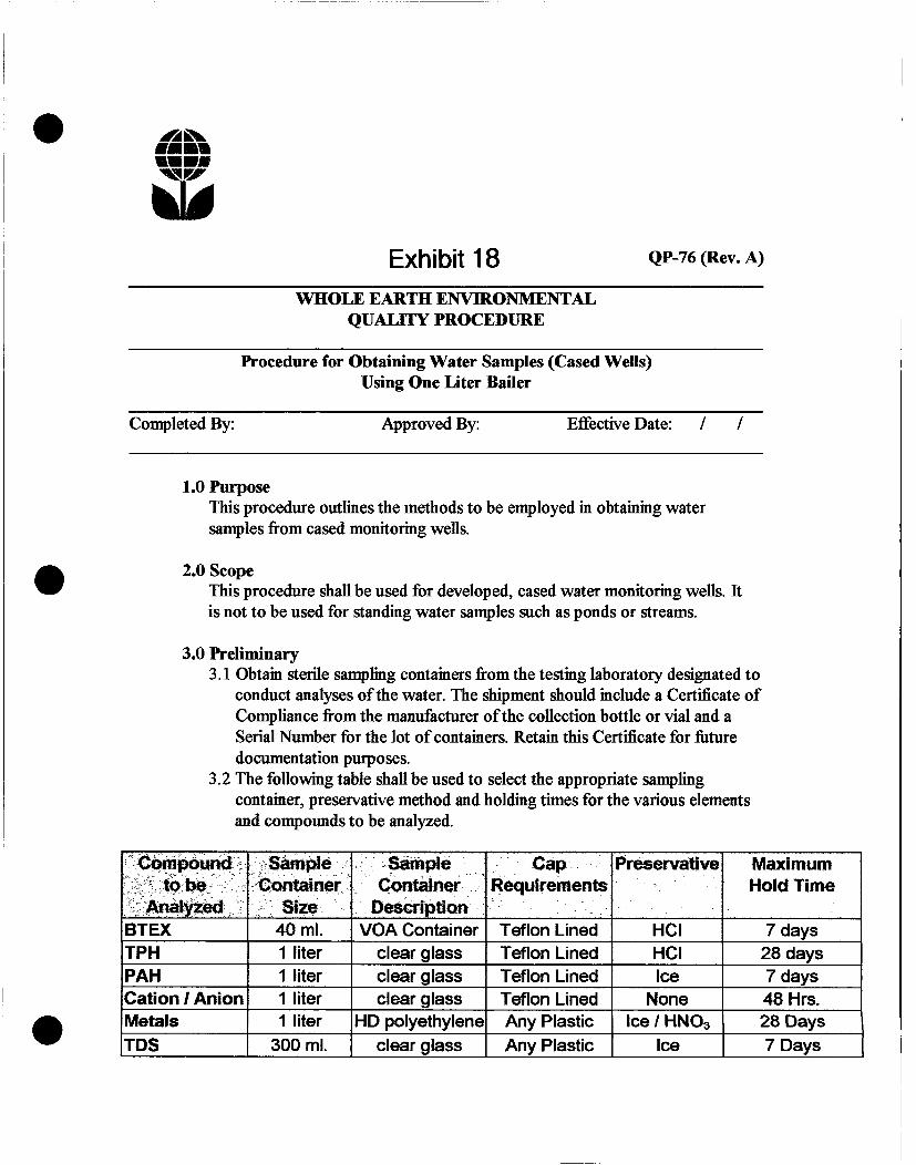
Exhibit 18 QP-76(Rev.A)
WHOLE EARTH ENVIRONMENTAL QUALITY PROCEDURE
Procedure for Obtaining Water Samples (Cased Wells) Using One Liter Bailer
Completed By: Approved By: Effective Date: / /
1.0 Purpose This procedure outlines the methods to be employed in obtaining water samples from cased monitoring wells.
2.0 Scope This procedure shall be used for developed, cased water monitoring wells. It is not to be used for standing water samples such as ponds or streams.
3.0 Preliminary 3.1 Obtain sterile sampling containers from the testing laboratory designated to
conduct analyses of the water. The shipment should include a Certificate of Compliance from the manufacturer ofthe collection bottle or vial and a Serial Number for the lot of containers. Retain this Certificate for future documentation purposes.
3.2 The following table shall be used to select the appropriate sampling container, preservative method and holding times for the various elements and compounds to be analyzed.
Compound to be
Analyzed
Sample Container
Size
Sample Container
Description
Cap Requirements
Preservative Maximum Hold Time
BTEX 40 ml. VOA Container Teflon Lined HCI 7 days TPH 1 liter clear glass Teflon Lined HCI 28 days PAH 1 liter clear glass Teflon Lined Ice 7 days Cation / Anion 1 liter clear glass Teflon Lined None 48 Hrs. Metals 1 liter HD polyethylene Any Plastic Ice / HN03 28 Days TDS 300 ml. clear glass Any Plastic Ice 7 Days

QP-76 Page 2
4.0 Chain of Custody 4.1 Prepare a Sample Plan. The plan will list the well identification and the
individual tests to be performed at that location. The sampler will check the list against the available inventory of appropriate sample collection bottles to insure against shortage.
4.2 Transfer the data to the Laboratory Chain of Custody Form. Complete all sections ofthe form except those that relate to the time of delivery of the samples to the laboratory.
4.3 Pre-label the sample collection jars. Include all requested information except time of collection. (Use a fine point Sharpie to insure that the ink remains on the label). Affix the labels to the jars.
5.0 Bailing Procedure 5.1 Identify the well from the site schematics. Place pre-labeled jar(s) next to
the well. Remove the bolts from the well cover and place the cover with the bolts nearby. Remove the plastic cap from the well bore by first lifting the metal lever and then unscrewing the entire assembly.
5.2 The well may be equipped with an individual 1 liter bailing tube. I f so, use the tube to bail a volume of water from the well bore equal to 10 liters for each 5' of well bore in the water table. (This assumes a 2" dia. well bore).
5.3 Take care to insure that the bailing device and string do not become cross-contaminated. A clean pair of rubber gloves should be used when handling either the retrieval string or bailer. The retrieval string should not be allowed to come into contact with the ground.
6.0 Sampling Procedure 6.1 Once the well has been bailed in accordance with 5.2 of this procedure, a
sample may be decanted into the appropriate sample collection jar directly from the bailer. The collection jar should be filled to the brim. Once the jar is sealed, turn the jar over to detect any bubbles that may be present. Add additional water to remove all bubbles from the sample container.
6.2 Note the time of collection on the sample collection jar with a fine Sharpie.
QP-76 Page 3
6.3 Place the sample directly on ice for transport to the laboratory. The preceding table shows the rnaximum hold times between collection and testing for the various analyses.
6.4 Complete the Chain of Custody form to include the collection times for each sample. Deliver all samples to the laboratory.
7.0 Documentation 7.1 The testing laboratory shall provide the following minimum information:
A. Client, Project and sample name. B. Signed copy ofthe original Chain of Custody Form including data on
the time the sample was received by the lab. C. Results of the requested analyses D. Test Methods employed E. Quality Control methods and results

J u n 0 1 Q l 1 2 : 1 2 p p . 4
I V l p i e p u e j g
>|np»M3S-8Jd) i v i Hsna
t -
p>
s o to
I O tt:
8 Uj or >-Q
e to =9 o &
HJ
E Z
8 5" ct
CD
X LU
e
tf) J*? CD t -X T T A i rt rt DJ u w
! US tfl
u> ui
CTJ
CO
C 0)
tf) CO
LU o>
v.
UJ
V i
£ E
ro
5"
2
OEOS/9U09 X3J.9
ssiqeiuAiiuss
OS 6H Qd JO PD BG 6v*sv «IBISW
oaa/oaowtosHdi 900IK001 X I H d l
D 3 / W S / 1 0 / S Q 1
ty
C Oc
N 1
•J Ci
5±.
— 0)
3 C g UJ s
3
C
£5
CL E «
to
.{Ajioeds) jvt i io
IMS
•Bpnis
HO»N
DH
sJ3Utej.uoo i ° 'ON
paidiUEs s t u n
paidoiES ajEQ
V
Vr T
i 'vrfi
f t
o
\
V
i
i
3
3
NT
g O
3
•Oi •JV.. t i l . . .
Tlx.: .••fl*:::
«y O
i- . -
o ^

J u n 0 1 0 1 1 2 : 1 2 p p . 3
ENVIRONMENTAL
LAB OF <J , INC.
Exhibit 19A
"Don't Treat Your Soil Like Dirt!'
Sample Type: Water Sample Condition: Intact/ Iced/ 1.5 deg C Project # : None Given Project Name: E-15 Project Location: Eunice, N.M.
WHOLE EARTH ENVIRONMENTAL ATTN: MR. MIKE GRIFFIN 19606 SAN GABRIEL HOUSTON, TEXAS 77084 FAX: 281-646-8996
Chloride mg/L
Sampling Date; 05/23/01 Receiving Date: 05/24/01 Analysis Date: 05/29/01
40425 40426
MW-3 MW-4
1312 674
QUALITY CONTROL TRUE VALUE 5 0 0 0
% INSTRUMENT ACCURACY 103 BLANK < 1 0
Methods: EPA SW 846-9253
P LV d / i ; Q ^-z9-o/ r Raland K. T u t W Date
12600 West I-20 East • Odessa, Texas 79765 • (915) 563-1800 • Fax (915) 563-1713

J u n 0 1 0 1 1 2 : 1 l p
ENVIRONMENTAL Exhibit 1 9B
LAB OF , INC.
p . c
"Don't Treat Your Soil Like Dirt!"
Sample Type: Water Sample Condition: Intact/ Iced/ HCI/ 1.5 deg. Project # : None Given Project Name: E-15 Project Location: Eunice, N.M.
WHOLE EARTH ENVIRONMENTAL INC. ATTN: MR. MIKE GRIFFIN 19606 SAN GABRIEL HOUSTON, TEXAS 77084 FAX: 281-646-8996
ELT# FIELD CODE BENZENE TOLUENE
mg/L mg/L ETHYLBENZENE
rng/L
Sampling Date: 05/23/01 Receiving Date: 05/24/01 Analysis Date: 05/24/01
m,p-XYLENE mg/L
o-XYLENE mg/L
40425 40426
MW-3 MW-4
•cO.001 <0.001
<0.001 <0.001
<0.001 <0.001
<0.001 <0.00l
•eO.OOl <0.001
QUALITY CONTROL 0.094 0.093 0.096 0.191 0.099 TRUE VALUE 0.100 0.100 0.100 0.200 0.100 % INSTRUMENT ACCURACY 94 93 96 96 99 SPIKED AMOUNT 0.100 0.100 0.100 0.200 0.100 ORIGINAL SAMPLE <0.001 <0.001 <0.001 <0.001 <0.00l SPIKE 0.096 0.094 0.098 0.193 0.100 SPIKE DUP 0.088 0.088 0.091 0.178 0.093 % EXTRACTION ACCURACY 96 . 94 98 96 100 BLANK <0.001 <0.001 <0.00l <0,00l <0.00l RPD 9 6 7 8 7
METHODS: EPA SW 846-8021B ,5030
Ralartd K. Turtle Date
12600 West I-20 East • Odessa, Texas 79765 • (915) 563-1800 • Fax (915) 563-1713

Abatement Plan
Current Site Status The site has been fenced with four-strand barbed wire perimeter and contoured to direct any storm water run-off to the excavated area. An open excavation having the approximate dimensions of 60' X 60' X 15' remains at the center of the site. The corroded connection leading to the spill event has been repaired.
Extensive soil borings and surface testing have been employed to detenriine the vertical and lateral extent of soil contamination. Additional investigations included thedrilling, casing development and testing of four monitor wells. The enclosed plat map (Exhibit 7) provides an accurate, surveyed location for each such monitor well.
Abatement Options (Soil) The site has no significant hydrocarbon contamination. The sole criteria contaminant is chlorides. The American Petroleum Association guideline, "Remediation of Salt-Affected Soils at Oil and Gas Production Facilities", (publication no. 4663, dated October 1997), lists eight potential remediation alternatives and provides a decision tree to arrive at the option most appropriate to an individual site. The following is a brief discussion of each of these options.
Natural Remediation Under this scenario, the site would slowly revert to background concentrations through simple dilution. In some cases, halophytic (salt tolerant) plants such as rye grass may be sown at the surface to promote the movement of salt into a biotic system. The plants will eventually be harvested, grazed or allowed to simply die out and blow away resulting over time in slightly lower soil salt concentrations through the process of dilution.
This option is deemed inappropriate due to several fectors. Testing has shown that the contaminant plume extends up to 70' below ground surface. Natural attenuation relies primarily on rainfall as the driver to move the salt from the various lenses. A comparison of the precipitation / pan evaporation tables enclosed as Exhibits 19 & 20 shows the area to have a negative 88" per year precipitation / evaporation ratio. Natural attenuation of this site will result in a slow but constant capillary migration of the salts both to the ground surface and the water table.

Page 2
In-Situ Chemical Amendments Under this scenario, the soils would be treated with either a solid amendment such as gypsum or liquid amendments such as calcium nitrate or potassium sulfate. The process works on the basis of ion exchange in which the electrical bond between the sodium chloride molecule and the soil platelets is broken, allowing the release of the salt into solution.
The process requires significant amounts of water. Exhibit 21 calculates the amount of calcium nitrate and water needed to achieve a target electrical conductivity (EC) result of <9mmhos/cm to be 390 barrels in solution whh 1,470 barrels of water. Using a minimum 3:1 flush ratio, this method will require the injection, collection and disposal of a minimum of7,440 barrels of brine water from a depth of 75' BGS.
Land Spreading This treatment method requires that the soils be spread evenly over an area large enough to decrease the contarninant concentration to an acceptable level. We estimate that the site contains approximately 12-15,000 cubic yards of contarninated soils having an average chloride concentration of 1,200 ppm. Assuming an acceptance standard of 250 ppm, it will be necessary to dilute the soils at a 4.8:1 to achieve acceptance standards. This will require the addition of between 58,000-72,000 cubic yards of dilution material. Spread over a six-inch lift, the resulting spread zone will be between 87-127 acres.
This option will necessarily require excavation to a depth of 75' BGS and that replacement soils be obtained to refill the excavation.
Road Spreading The New Mexico OCD generally does not allow salt contaminated soils to be used as road spread material. Assuming only 12,000 cubic yards of contaminated soils to be involved and further assuming the standard width of a lease road to be 40', it would require a length of almost three miles of distance to spread the soils to an average depth of 6".
This option will necessarily require excavation to a depth of 75' BGS and that replacement soils be obtained to refill the excavation.
Disposal in Landfill This option is simply to excavate the contarninant plume and transport it to a commercial facility for disposal. Some of the contarninated materials may be mixed and diluted with replacement soils before being re-deposited within the excavation.

Page 3
The main disadvantage to this method is the cost-estimated to be at least $25.00 per excavated cubic yard. Nothing will be done to remediate the contamination, it will simply be moved somewhere else.
In-Situ Soil Washing This method was generally described in the Chemical Amendments section of this report. A variant of this method is to erect a tile and drain system in which the area is constantly flooded with fresh water later sent to disposal.
Ex-Situ Soil Washing Soil washing requires that the plume be excavated and transported to a mobile treatment plant. The soil will then be crushed and subjected to a series of chemical treatments, rinses and drying stations.
Again, the main disadvantage is cost. Due to its' high porosity, calichi is exceedingly difficult to wash.
Encapsulation There are two main variants to this method. The first is to mix water and a binding agent such as fry ash, lye or cement into the contarninant plume to produce a non-leachable amalgam. This amalgam would be left in place. The second is to construct an impermeable outside barrier such as clay or plastic to prevent contarninant migration.
Our protocol is based upon yet another variant of this technique. Using a risk based corrective action (RBCA) approach to the project, we propose to excavate and encapsulate the bulk of the contaminant plume within an impermeable, high-density polyethylene liner. A shnilar top liner will be installed and overlapped with the lower liner at a minimum depth of 5' BGS. A secondary clay liner will be installed below the polyethylene liner to insure a near zero vertical infiltration rate.
The liners serve as a vertical tramrnissivity barrier to the percolation of rainwater through the vadose zone. With no vertical driver, the portion of the plume lying beneath the liner will tend to remain hydrologically inactive. VADSAT modeling (Exhibits 22 & 23) indicates that the remaining plume will not pose a future threat to the environment. The detailed closure protocol, PR-62 is enclosed as Exhibit 24.
Abatement Option (Water) The contaminant plume Ues immediately adjacent to a water disposal line managed by Rice Operating Company. A windmill, temporary storage tank and ancillary equipment will be erected at the present site of MW-1. The waters underlying the site will be

Page 4
pumped out and transported through existing lines to SWDW-N18. NMOCD Salt Water Disposal Order Form D-184 is included as Exhibit 25. The recovery well will be tested for chloride concentrations each quarter and will remain in service until such concentrations meet NMWQCC standards for a period of four consecutive quarters.

I W I
Abatement Plan Exhibit Index
19. Central Southwest USA Normal Annual Total Precipitation Map
20. Western USA Mean Annual Class A Pan Evaporation Map
21. Loading Calculations Worksheet
22. NaCl Migration Model Data
23. VADSAT Concentration vs. Time Probability Model
24. PR-62 Spill Remediation Protocol
25. NMOCD Salt Water Disposal Order Form SWD-184

Central Southwest USA Normal Annual Total Precipitation Map
1-6

Exhibit 20

Exhibit 21 mmm* mmmm
m\0 Rice Operating Company
J.R E-15 Ixiadine ( alculations Worksheel
r n n t a — k i l l i w T n t 1 Ml
1 IIIUMI
•r Depth ,'5
Y d ' 15.000 Surface Acres 0 1240 8CJ.PL
Analytical Data E-1S
% Molst iae SoN Sample S o M a pH (7 • )
• S c M s E l e c t r i c Conducttvty(E.C. )<M 3) 38 3 S o M a Cadon Exchange Capacity (C.E.C.X 20 1) ro i S o M a Exchangeable Sodium Percentage ( E . S . P . ) C 3 6) ?8 6 Sodhan Adsorption Ratio <' < 54
Optional Values E - K Sac*ground E . C . (1) 1
Target E . C . (S)
'• Target S A R . (<12) 12 Sample S o M s T P H % 0
Background T P H % M ) 0 1 Disking Depth, (") (•) 6 Max. Spread Depth 1
Limiting Parameters (L.P.) £-16 Contaminant Concentration In Soil oooooo Background Concentration oooooo Target Concentration 3 00COC
WW / Dry Valuaxi Caku ia t ton i E-1S
Wat Y d 1 S o M a 15 000
Dry V d 1 S o M a • t 296
Dilution Option Calculations E - K
Additional SoBs Raquked E X . (Yd 3 ) 5? S21
AddRtonal SoBs Requked L.P. (Yd 1 ) N / A A c r a * Requked tor tp leading 8 4 8 Y d 3 to be Land spread 66 586
Oypoura Loading Calculat ions E-11 T o m L b s . Oypaum Raquked 50 230 • R E P ! L b s . SuVur Requked 8 860 • R E P ! Acres Requked tor Spreading 18 5950 Barrels of water Raquked •N'A
C a B o ' LoaoTng Calculat ions E-1S Barrels Cakdum HBrate 0 11.M0 meq 1 L Bora, of Water Raquked 1 470 No. of AppBcattona Raquked N / A
c . i s
L b s . of Nitrogen ••ie N / A L b s . of Phosporus N / A
L b s . of Potassium N / A ! ! » R » ! E-1S
Lbs. Ammonium Sulfate N / A L b s . Concentrated Super Phosphate N / A L b s . Muriate of Potash N / A

7* "

Exhibit 22
mmmm V ' /
Modeling Data Entry Rice Operating Co. Junction Box E-15
NaCl Migration Model
Control Data Entry U / M Deterministic Y r s
Final Time 73,000 Days Time Interval 365 Days
Monte Carlo No Low Permeability Layer Below Contamination No
Waste Zone Thickness 30 meters Waste Zone Area 500 sq meters Ratio of Length to Width 00:000 Soil Thickness Above Waste Zone 5 meter Initial Total Concentration in Waste 2 600 ppm
Chemical Data NaCl Yes|
Unsaturated Zone Soil Database Clay Hydraulic Conductivity 0.00011 meters/day Hydrological Database Bedded Sedimentary Unsaturated Zone Thickness 8 meter Soil Database Clay van Genuchten n 1.09 (Default) Residual Water Content 0.011 Unsaturated Zone Dispersivity 0 Internally
Saturated Zone Aquifer Porosity 0.2 (Default) Longitudinal Dispersivity 0 Internally Ratio of Long / Trans Dispersivities 1 Ratio of Trans. / Vert. Dispersivities 87 Hydrological Database Bedded Sedimentary Aquifer Thickness 10 meters Aquifer Gradient 0.00928 Saturated Hydraulic Conductivity 0.13 meters / day
|Net Infiltration Rate 1 0 00001 ft. / day

Cl /Om NOI1U^1N33NOD

^m%.
mm Exhibit 24 PR-62
Spill Remediation Protocol Rice Operating Co. Junction Box £-15
1.0 Purpose This protocol is provide a detailed outline of the steps to be employed in the remediation and final closure of a spill area adjacent to Rice Operating Co. Junction Box E-15.
2.0 Scope This protocol is site specific.
3.0 Preliminary Prior to any field operations, Whole Earth Environmental shall conduct the following activities:
3.1 Client Review 3.1.1 Whole Earth shall meet with cognizant personnel within Rice Operating Co.
(ROC) to review this protocol and make any requested modifications or alterations prior to submittal to the State of New Mexico Oil Conservation Division.
3.1.2 Changes to this protocol will be documented and submitted for final review by ROC prior to submittal to the Oil Conservation Division.
3.2 Oil Conservation Division Review 3.2.1 Upon client approval, this protocol and associated modeling results will be
submitted to the New Mexico Oil Conservation Division for review and comment. Recommended changes will be reviewed by the client prior to implementation.

PR-62 Page 2
3.2.2 Any recommended changes effecting costs will require a revised quotation to be issued to the client for approval prior to the commencement of any on-site remediation activity.
4.0 Safety 4.1 Prior to work on the site, Whole Earth shall obtain the location and phone numbers ofthe nearest emergency medical treatment facility. We will review all safety related issues with the appropriate ROC personnel, sub-contractors and exchange phone numbers.
4.2 A tailgate safety meeting shall be held and documented each day. All subcontractors must attend and sign the daily log-in sheet.
4.3 Anyone allowed on to location mast be wearing sleeved shirts, steel toed boots, and long pants. Each vehicle must be equipped with two way cornnmtiicatiott capabilities.
4.4 Prior to any excavation, tke area shall be surveyed with a line finder. I f lines are discovered within the area to be excavated they shall be marked with pin flags on either side ofthe line at maximum five foot intervals.
5.0 Excavation & Remediation 5.1 The site shall be excavated to a rninimum depth of 35' BGS. All materials will be deposited immediately adjacent to the excavation.
5.2 Each of the four side-walls and bottom will be will be tested on a rninimum five point composite basis for the presence and concentrations of TPH, BTEX and chlorides. The Hobbs office of the NMOCD will be alerted a minimum of twenty-four hours in advance of any sampling event. Soil samples will be collected in accordance with WEQP-77 and transported to a lab for analysis.
5.3 The sidewalls ofthe site shall meet the following criteria contarninant concentrations:

PR-62 Page 3
Benzene: 10 ppm BTEX: 50 ppm TPH: 100 ppm Chlorides: 250 ppm
5.4 The bottom ofthe excavation must meet the benzene, BTEX, and TPH requirements specified in 5.3 and have a maximum chloride concentration of 2,000 ppm.
6.0 Qay Liner Upon reaching a njinimum depth of 35'BGS and achieving the closure standards specified within 5.4, a clay liner will be installed and compacted to a minimum depth of 12". The liner will meet or exceed 95% of a Proctor Test ASTM D-698 with a permeability (hydraulic conductivity) equal to or less than 1X10"7 cm/sec for containment / isolation of impact.
7.0 Lower Polyethylene Liner Upon installation ofthe clay liner, a 20 mil polyethylene liner will be constructed to cover the contour of the excavation up to surface level. The previously excavated soils will be re-deposited within the liner to a depth no less than 5' BGL.
8.0 Upper Liner A 20 mil high density polyethylene top liner will be installed above the excavated area and overlapped with the lower liner to prevent surface drainage into to the containment area. The surface will be covered with a niinimum of 5' of fresh topsoil and contoured to match the surrounding elevations.
9.0 Recovery & Monitoring Wells 9.1 At the completion ofthe surface remediation portion of the project, a recovery well will be installed at the location ofthe existing MW-1. The recovery well will be a minimum 4" diameter and drilled at least 10' into the water table. A windmill will be erected over the well and all pumped fluids diverted to disposal well N-l8.
9.2 Delineation wells will be drilled down gradient of the plume to determine the lateral extent of contamination.
10. Monitoring 10.1 The recovery well and each monitoring well will be sampled on quarterly basis for the presence and concentrations of chlorides. Final site closure will occur after the recovery well and all monitoring wells meet NMWQCC standards for a period of four consecutive quarters.

11.0 Documentation & Reporting 11.1 At the conclusion of the pit remediation project, Whole Earth will prepare a
closure report to include the following information:
• A plat map of the location showing the exact location of the pit, the dimensions prior to excavation and the actual excavated dimensions.
• Photographs ofthe site prior to excavation, at the point of maximum excavation, liner installation details, and after final closure
• Design and construction details of the drawdown and monitoring wells. • Design and construction details of the windmill and ancillary piping. • Laboratory analytical results of the sidewalls and bottom of the excavation • MSDS of the polyethylene liners • Proctor and density tests of the clay liner.

SUBJECT: SALT WATER DISPOSAL WELL ORDER KO. SI;D-1S4
THE APPLICATION 0. AGUA, INC. FOR
A SALT WATER DISPOSAL WELL. £*XH"l8lT 2,5 ADMINISTRATIVE ORDER
OF THE OIL CONSERVATION COMMISSION
Under the provisions of Rule 701 (C) Agua, Inc. made application to the New Mexico O i l Conservation Commission on June 13, 1977 for permission to complete for aalt water disposal i t s Blinebry-Drinkard SWD System Well No. 13 located in Unit N of Section 18, Township 22 South, Range 37 East, NMPM, Lea County, New Mexico.
The Secretary-Director finds:
1. That application has been duly f i l e d under the provisions of Rule 701 (C) of the Commission Rules and Regulations;
2. That satisfactory information has been provided that a l l offset operators and surface owners have been duly n o t i f i e d ; and
3. That the.applicant has presented satisfactory evidence that a l l requirements prescribed i n Rule 701 (C) w i l l be mat.
4. That no objections have been received within the waiting period prescribed by said rule.
IT 13 THEREFORE ORDERED;
That the applicant herein, Agua, Inc. i s hereby authorized to complete I t s Blinebry-Drinkard SWD System Well Ko. 18 located i n Unit N of Section 18, Township 22 South, Range 37 East, NMPM, Lea County, New Mexico, i n auch a manner as to permit the injection of salt water for disposal purposes into the San Andres formation at approximately 4000 feet to approximately 5000 feet through 5% inch plastic lined tubing set i n an o i l column extending from approximately 4000 feet to the surface.
IT IS FURTHER ORDERED:
That the operator shall take a l l steps necessary to ensure that the injected water enters only tha proposed injection interval and is not permitted to escape to other formations or onto the surface.
That tha casing-tubing annulus shall ba equipped with a pressure gauge st the surface or l e f t open to the atmosphere to f a c i l i tate detection of leakage In the casing or tubing;
That injection pressures shall be limited to 800 pounds per square inch asmsasured at the surface.
That the operator shall notify the supervisor of the Commission's Hobbs Oistrict Office before injection is commenced through said well.
That the operator shall immediately notify the supervisor of the Commission's Hobbs District Office of the failure of the tubing or casing i n said well or the leakage of water from or around said well and shall take auch steps as may be timely or necessary to correct such failure or leakage.

PROVIDED FURTHER:
That jurisdiction of thia cause is hereby retained by the Commission for such further order or orders as may seen necessary or convenient for the prevention of waste and/or protection of correlative rights; upon failure of applicant to comply with any requirement of this order after notice and hearing, the Commission may terminate the authority hereby granted in the interest of conservation. That applicant shall submit aionthly reports of the disposal operation in accordance with Rule 704 and 1120 of the Commission Rules and Regulations.
APPROVED at Santa Fe, New Mexico, on this 13th day of July, 1977.
STATS OF NEW MEXICO OIL CONSERVATION COMMISSION
JOE D. RAMEY Secretary-Director
S E A L

RICE Operating Company 122 West Taylor • Hobbs, New Mexico 88240 Phone: (505)393-9174 • Fax: (505) 397-1471
June 5, 2001
Mr. Robert Cueto P. O. Box 56 Eunice, NM 88231
Dear Mr. Cueto:
Enclosed please find the results of the groundwater analysis for the new monitor well and updated copies of the information submitted to the NMOCD for the accidental discharge site Jet. E-15 of the Blinebry Drinkard SWD System. Rice Operating Company (ROC) has submitted Stage I and Stage I I , developed by Whole Earth Environmental, Inc. to the NMOCD for remediation plans at this site.
As events develop, you will be informed of progress. ROC appreciates your patience in the remediation at this site. I f you have any observations, questions or concerns, please do not hesitate to call me at the above phone number.
Thank you,
RICE OPERATING COMPANY
Carolyn Doran Haynes Operations Engineer
Enclosures
cc: LBG, Whole Earth, NMOCD, file

RICE Operating Company 122 West Taylor • Hobbs, New Mexico 88240 Phone: (505)393-9174 • Fax: (505) 397-1471
June 5, 2001
Mr. Irvin Boyd P. O. Box 121 Eunice, NM 88231
Dear Mr. Boyd:
Enclosed please find the results of the groundwater analysis for the new monitor well and updated copies of the information submitted to the NMOCD for the accidental discharge site Jet. E-15 of the Blinebry Drinkard SWD System. Rice Operating Company (ROC) has submitted Stage I and Stage I I , developed by Whole Earth Environmental, Inc. to the NMOCD for remediation plans at this site.
As events develop, you will be informed of progress. ROC appreciates your patience in the remediation at this site. I f you have any observations, questions or concerns, please do not hesitate to call me at the above phone number.
Thank you,
RICE OPERATING COMPANY
Carolyn Doran Haynes Operations Engineer
Enclosures
cc: LBG, Whole Earth, NMOCD, file