Embed Size (px)
Citation preview

Effi ciency
as standard
Stage II / Tier 2Stage IIIA / Tier 3
Wheel Loaders L 538 / L 556 / L 580
Tipping load, articulated: 9,500 kg - 18,000 kg

2 L 538 / L 556 / L 580
L 538Tipping load, articulated: 9,500 kg
Bucket capacity: 2.5 m3
Operating weight: 12,800 kg
Engine output: 104 kW / 141 HP
L 556Tipping load, articulated: 12,900 kg
Bucket capacity: 3.5 m3
Operating weight: 17,400 kg
Engine output: 140 kW / 191 HP
L 580Tipping load, articulated: 18,000 kg
Bucket capacity: 5.0 m3
Operating weight: 24.720 kg
Engine output: 209 kW / 284 HP

L 538 / L 556 / L 580 3
ReliabilityAll the materials used have passed long-term tests to ensure
that they comply with Liebherr’s high quality standards in even
the toughest conditions. A sophisticated concept and proven
quality mean that Liebherr wheel loaders are specially designed
for your market to set the standard when it comes to reliability.
ComfortThe ultra-modern cabin design with advanced ergonomics,
Liebherr driveline, optimal weight distribution and excellent
maintenance access lead to unequalled overall comfort and
simple service.
EconomyWith Liebherr wheel loaders it is simple to do more, moving
larger volumes of material with less fuel compared with conven-
tional wheel loaders. In fact, your production costs are greatly
reduced with each bucket you load and, at the same time, lower
fuel consumption means active protection of the environment.
PerformanceLiebherr wheel loaders are specially designed for your market
to meet the highest requirements. The ideal positioning of the
Liebherr driveline moves the center of gravity to the rear of the
wheel loader - meaning increased stability and no lifting of the
rear. This greatly increases the handling capacity per operating
hour compared with conventional wheel loaders.

2
5
4
3
115
20
25
30
35n=?
20m
T ~
35
sec.
2,5
m
A
B
4 L 538 / L 556 / L 580
Lower fuel consumption
• A fuel saving of up to 5 litres
per operating hour represents
a cost saving of up to 25 %.
• The Liebherr standard test demon-
strates the operating effi ciency of
Liebherr wheel loaders.

L 538 / L 556 / L 580 5
An all-purpose loader
• The use of innovative Liebherr
driveline and high quality hydraulic
components mean increased sta-
bility, no lifting of the rear and faster
work cycles - perfectly matched for
your applications and thus increas-
ing effi ciency.
Reduced tyre wear
• The tractive force can be adjusted
continuously. This prevents wheelspin
and reduces tyre wear by up to 25 %.
Reduced brake wear
• Even in the toughest working con-
ditions, the Liebherr travel drive is
always braked hydraulically. The me-
chanical service brake is used only as
a secondary braking function, so the
brakes are virtually wear-free.
With Liebherr wheel loaders it is simple to do more, moving larger volumes of material
with less fuel compared with conventional wheel loaders. In fact, your production costs
are greatly reduced with each bucket you load and, at the same time, lower fuel consump-
tion means active protection of the environment.
Low operating costsMoving material
at lower costs
When it comes to economy, conventional wheel loaders
are no match for Liebherr machines, mainly due to the
following factors:
− Low fuel consumption as a result of higher effi ciency
and a lower operating weight.
− Virtually no brake wear, thanks to the hydraulic braking
action of the driveline. This means no brake repair costs
resulting from wear and tear.
− Continuous traction control for reduced tyre wear. De-
pending on the working conditions, tyre wear can be
up to 25 % lower than with conventional wheel loaders.
– Liebherr quality ensures high durability and reliability
in even the toughest applications and therefore less
downtime and more productivity.
Active environmental protectionEconomical use
of resources
Reduced fuel consumption means lower emissions, which
leads to the active and economical use of resources.
Low noise emissions The innovative driveline concept also cuts noise emis-
sions considerably: Liebherr wheel loaders are signifi -
cantly quieter in operation.
Economy

6 L 538 / L 556 / L 580
Liebherr driveline L 538, L 556
• Optimum weight distribution
due to transverse installation
of the diesel engine.
• The diesel engine as well as the
variable displacement pumps
mounted on the engine act as
counterweight, thus allowing
higher tipping loads at low
operating weight.
• Compact design improves
visibility in all directions.

L 538 / L 556 / L 580 7
Liebherr driveline L 580
• Optimum weight distribution thanks
to lengthways-installed diesel engine,
output shaft is facing to the rear.
• The diesel engine as well as the varia-
ble displacement pumps mounted on
the engine act as counterweight, thus
allowing higher tipping loads at low
operating weight.
• Compact design improves visibility
in all directions.
Conventional travel gear
• Longitudinally mounted diesel
engine moves the centre of
gravity further forward.
• Additional counterweight is
needed to maintain stability
and to increase the tipping load.
• This leads to high operating
weight and bad visibility.
Liebherr wheel loaders are specially designed for your market to meet the highest re-
quirements. The ideal positioning of the Liebherr driveline moves the center of gravity to
the rear of the wheel loader - meaning increased stability and no lifting of the rear. This
greatly increases the handling capacity per operating hour compared with conventional
wheel loaders.
Higher performanceHigher productivity The ideal positioning of the Liebherr driveline reduces the
need to carry unnecessary counterweight on the machine
compared with conventional wheel loaders - leading to re-
duced operating weight and increased productivity.
Ultra-modern Liebherr drivelineInnovative
hydrostatic technology
Tractive force and speed are adapted to suit demand –
automatically and without gear changes. Even the change
from forward to reverse travel is controlled hydraulically,
so that no mechanical reverse gear is required.
Powerful HydraulicsReduced input,
higher output
The use of high quality hydraulic components combined
with the innovative Liebherr driveline result in less need
of engine power - leading to an easy fi lling of the bucket,
faster work cycles and perfectly matched engine perfor-
mance.
Flexibility puts them aheadAn all-purpose loader Their compact design combined with the excellent dump-
ing height allow the wheel loaders to manoeuvre quickly
and effi ciently when loading big trucks – an ideal basis for
high handling capacity.
Performance

8 L 538 / L 556 / L 580
Cooling system L 538, L 550
• The radiator is installed at the
cleanest position of the wheel
loader, between the diesel en-
gine and the cabin. Cooling air
is drawn in directly behind the
cabin and blown out upwards at
the rear. The fan speed is varied
automatically by heat sensors
that determine the amount of
cooling needed.

L 538 / L 556 / L 580 9
Cooling system L 580
• The cooling system is mounted
between the diesel engine and the
cab on the rear carriage, where it
can draw in clean air. The speed of
the fan is dependent on the cooling
capacity, with thermosensors ensur-
ing optimum fan speed.
• To improve visibility, the cooler pack-
age has been mounted lengthways,
and the unit has been redesigned to
make cleaning and maintenance even
easier, achieving greatest possible
convenience.
Liebherr quality
• Liebherr has many years of expe-
rience in the design, development
and construction of wheel loaders.
The high quality of steel structures,
equipments and the use of compo-
nents that are all matched together
down to the smallest detail set the
standard when it comes to reliability.
All the materials used have passed long-term tests to ensure that they comply with Lieb-
herr’s high quality standards in even the toughest conditions. A sophisticated concept and
proven quality mean that Liebherr wheel loaders are specially designed for your market to
set the standard when it comes to reliability.
Reliable Liebherr drivelineFewer components Liebherr’s driveline includes a self-locking hydraulic brake,
with the result that the additional wet brake discs are ef-
fectively wear-free. A reversing gear unit is not required, so
less parts are affected by wear.
Components to Liebherr’s quality standardsEngineered
by Liebherr
Engineered by Liebherr means co-ordinated quality from
the manufacture down to the smallest detail to ensure the
highest possible performance and reliability for the market.
Keep on working -
in the toughest
conditions
Liebherr wheel loaders are built to keep on working and
prevent costly downtime. No matter how tough the con-
ditions are.
Controlled coolingThe intelligent answer Wheel loaders usally work in dusty environments, so the
Liebherr cooling system is located directly behind the
cab, which is the cleanest area of the wheel loader. This
greatly increases the service life and ensures the most
reliable cooling. The cooling fan is driven independently
from the diesel engine and produces only the cooling air
output which is actually required. Heat sensors ensure reli-
able control. If overheating should occur, the wheel loader
automatically shifts down to fi rst travel speed range. The
reduced power consumption protects the engine from
overheating. At the same time, the fan speed is increased
to maximum output, thus preventing the engine from over-
heating.
Reliability

10 L 538 / L 556 / L 580

–
–
–
–
L 538 / L 556 / L 580 11
Service accessibility
• Due to the unique position of the
diesel engine, Liebherr wheel loaders
offer excellent service accessibility
and thus increase effi ciency for daily
maintenance.
• The clever positioning of the cooling
package, directly behind the cab,
reduces maintenance and cleaning.
Liebherr joystick
• The Liebherr control lever is used to manage all travel
and working movements of the wheel loader. This
ensures the operator’s left hand always remains on
the steering wheel and therefore increases safety.
The operator controls the following functions with
his right hand:
The ultra-modern cabin design with advanced ergonomics, Liebherr driveline, optimal
weight distribution and excellent maintenance access lead to unequalled overall comfort
and simple service.
Top-class cabin designComfortable
cabin - productive
operator
The ultra modern cabin is especially designed for the operator’s
needs and ensures increased performance and productivity, as
well as safe operation. ROPS and FOPS are standard on Liebherr
wheel loaders.
Improved visibility The advanced cab design, combined with the compact dimensions
of the wheel loader, provide unequalled visibility in all directions.
Liebherr joystick All working and travel functions are operated precisely and sen-
sitively from a single control lever. This means accurate and safe
handling, and the left hand always remains on the steering wheel.
This increases the safety at the job site.
Liebherr drivelineContinuously varia-
ble acceleration
Liebherr’s driveline enables the wheel loader to accelerate smooth-
ly and continuously in all speed ranges, with no discernable gear
shifts and no interruptions to tractive force.
Service accessibilityEasy maintenance With the unique position of the diesel engine, Liebherr wheel load-
ers provide outstanding accessibility for maintenance. The posi-
tioning of the cooling system directly behind the cab results in less
contamination, which in turn reduces maintenance and cleaning; a
clear benefi t which saves time and money.
L 538, L 556 All the points for daily maintenance can be reached from ground
level by opening a single compartment hood. Cleaning of the cool-
ing system is carried out while standing on the machine, anti-slip
step surfaces and strong handrails in the access area ensure a
high safety standard.
L 580 Most access points for daily maintenance can be reached from
ground level, by opening a single engine compartment. Work on
the cooler unit, diesel engine and pump distributor gear is carried
out while standing on the machine. Great care has been taken to
ensure maximum safety in these areas as well.
Comfort
Raise and lower attachment
Fill and dump the bucket
Automatic bucket return to dig (optional)
Change of travel direction
with simultaneous travel start

12 L 538 / L 556 / L 580
Effi ciency as standard
Lift arm / Equipment Faster working cycles
Long lasting working equipment
Flexibility in use
High quality hydraulic components
Strong steel structure
Wide range of working equipment
Operator’s cab Increased performance and productivity
Excellent all-round visibility
Safe operation
The operator’s concentration is enhanced
Ergonomic cab design
High proportion of glass in the cab
ROPS / FOPS as standard
Control of working and travel functions
with one single joystick
Liebherr driveline Fuel saving of up to 25 %
Maximum productivity: High tipping loads at comparable low operating weight
Excellent manoeuvrability
Tyre wear reduced by up to 25 %
Practically no brake wear
Safe machine operation even when driving over rough terrain and steep slopes
Compact machine design due to the unique position of the drive components
No need for additional counter weight due to the ideal weight distribution
Continuous tractive force prevents wheelspin
Wear free hydrostatic self-braking system
aaaaaaaaaaaararararararrarararaarar blblblblblblblblblblblblbbblbb eeeeeeeeeeee lololoolololololololooow w w w wwww ww w ww opopopopopopopopopopopopperererererererererre atatatatatatatatatataaa ininininininninnining g gg ggg g g gg weweweweweweweweweweweweweww igiigigigigigigigigighththththththththththttt
ghghghghghghghgh ttttttttererererrrrerrarararararainininninininn aaaaaaandndndndnnddd sssssssssteteteteteet epepepepep ssssssslololoolooopepepepepeeesssss
nnnnnn ooooooof f fffff thththththhhhheeeee drdrdrdrdrd ivivivivve e e e e cocococococococ mpmpmpmpmppmm ononnonononenenenenenentstsstsstss
eaeaeaeaeaeaealllllll wewewewewewww igigigigghthththtt dddddisisisisstrtrtrtrt ibibibibbbututututu ioioioiooooonnnnn

L 538 / L 556 / L 580 13
Cooling system Reliable cooling, no overheating even in hard
applications and hot outside temperatures
Increased service life
Less service time due to less cleaning requirements
The cooling system is driven independently
from the diesel engine
Heat sensors ensure reliable control
The radiator is installed at the cleanest position
of the wheel loader, directly behind the cab
Service accessibility Time savings in daily maintenance
Extremely low downtime due to minimal
maintenance requirements
Daily maintenance points can be reached
from the ground by opening a single hood
Unique positioning of the cooling system,
directly behind the cab
SSSSSSSSSSeeeeeeeeerrrrrrrrvvvvvvvviiiiiiiicccccccceeeeeeeeee aaaaaaaaccccccccTTTTTTTTimimimiimimimme e ee e sasasasasasaaasavivivivivivviingngngngngngngg
EEEEExtxtxtxtxtrererereemememememelylylyly llllooooo
mmmmmmmaiaiaiaiaiaiaintntntntntntntenenenenenenenananaaanananncecececececee
DDDDDDaiaiaiaiaaaa lylylyly mmmmmmmaiaiaiaaaiaintntntntntnn eeeeeee
fffffffrrorororrom m mmm thththththheeee grgrgrgrgrgrooooooo
UUUUUUUnininininininin quququququuueeeeeee popopopoppp sisisiisittt
dddddddiriririiriri ececececeece tltltltllyy yy y bebebebebebeb hihihihih

14 L 538 / L 556 / L 580
Technical Data
EngineDiesel engine ����������������������� 4045HF286 Design ������������������������� water-cooled, turbo charged, intercooledCylinders inline ��������������������� 4Fuel injection process ������������� electronic Common Rail high-pressure injection Max. output according to DIN/ISO 3046 �������������� 104 kW at 2,400 RPM Max. torque ������������������� 525 Nm at 1,500 RPM Displacement ����������������� 4.5 litres Bore/Stroke ������������������� 106/127 mmAir cleaner system ����������������� Dry air filter with main and safety element,
pre-cleaner, service indicatorElectrical system Operating voltage ������������ 24 V Battery ������������������������ 2 x 135 Ah Alternator���������������������� 28 V/100 A Starter motor ����������������� 24 V/7 kW
The exhaust emissions are below the limits in Stage IIIA / Tier 3.
Travel DriveStepless hydrostatic travel drive Design ������������������������� Swash plate type variable flow pump and two
variable axial piston motors in closed loop circuit and axle transfer case. Direction of travel is reversed by changing the flow-direction of the variable-displace-ment pump
Filtering system �������������� Suction return line filter for closed circuit Control ������������������������ By travel and inching pedal. The inching pedal makes
it possible to control the tractive and thrust forces steplessly at full engine speed. The Liebherr joystick is used to control forward and reverse travel
Travel speed range ���������������� Speed range 1 ���������������������������� 0 – 4.0 km/h Speed range A1-2 ������������������������ 0 – 15.0 km/h Speed range A1-3 ������������������������ 0 – 40.0 km/h The quoted speeds apply with the tyres that are
standard equipment on the loader
AxlesFour-wheel driveFront axle ��������������������������� FixedRear axle ���������������������������� Centre pivot, with 10° oscillating angle to each side.
470 mm in height can be driven over (with all four wheels remain in contact with the ground)
Differentials ������������������������� Automatic limited-slip differentialsReduction gear ��������������������� Planetary final drive in wheel hubsTrack width ������������������������� 1,900 mm with all types of tyres
BrakesWear-free service brake ����������� Self-locking of the hydrostatic travel drive (acting on
all four wheels) and additional pump-accumulator brake system with wet multi-disc brakes located in the differential housing (two seperate brake circuits)
Parking brake ���������������������� Electro-hydraulically actuated spring-loaded disc brake system on the front axle
The braking system meets the requirements of the EC guidelines 71/320.
TyresStandard size ����������������������� 20.5R25 L3Special tyres ������������������������ By arrangement with the manufacturer
SteeringDesign ������������������������������ “Load-sensing” swash plate type variable flow pump
with pressure cut-off and flow control. Central pivot with two double-acting steering cylinders
Angle of articulation ��������������� 40° (to each side)Emergency steering ��������������� Electro-hydraulic emergency steering system, optional
Operator’s CabDesign ������������������������������ On elastic bearing on rear section, soundproof
ROPS/FOPS cab. Operator’s door with 105° opening angle, ventilation opening on the right hand side, front windscreen made of compound safety glass, green tinted as standard, side windows made of single-pane safety glass, grey tinted, continuously adjust able steering column and joystick control as standard, heatable rear window ROPS roll over protection per EN/ISO 3471/EN 474-1 FOPS falling objects protection per EN/ISO 3449/ EN 474-1
Liebherr Operator’s seat ���������� 6 way adjustable seat with lap belt, vibration damping and suspension adjustable for the opera tor’s weight (mechanically sprung)
Cab heating and ventilation ������� Operator’s cab with 4-level air control, cooling water heating, mechanical controlled heating as standard, mechanical controlled air-condition as option
Noise EmissionSound pressure, measured according to ISO 6396 (inside cab): ������������������������� LpA = 69 dB(A)Sound power, measured according to ISO 6395 (emitted by wheel loader): ���������� LWA = 103 dB(A)
CapacitiesFuel tank ������������������������������������������������������������������������������������� 225 lEngine oil (including filter change) �������������������������������������������������������� 14.7 lTransmission ���������������������������������������������������������������������������������3.8 lCoolant ��������������������������������������������������������������������������������������� 36 lFront axle/wheel hubs �������������������������������������������������������������� 16.3 l / 2.6 lRear axle/wheel hubs ������������������������������������������������������������������15 l /2.6 lHydraulic tank �������������������������������������������������������������������������������� 90 lHydraulic system, total ��������������������������������������������������������������������� 170 l
AttachmentGeometry ��������������������������� Powerful Z-bar linkage with tilt cylinder and steel
cross-tubeBearings ���������������������������� SealedCycle time at nominal load ������� Lifting ������������������������������������������������ 5.3 s Dumping �������������������������������������������� 1.6 s Lowering (empty) ����������������������������������� 4.0 s
Attachment HydraulicsDesign ������������������������������ “Load-sensing” swash plate type variable flow pump
with output and flow control, and pressure cut-off in the control block
Cooling ����������������������������� Hydraulic oil cooling using thermostatically controlled fan and oil cooler
Filtration ���������������������������� Return line filter in the hydraulic reservoirControl ������������������������������ “Liebherr-Joystick” with hydraulic servo controlLift circuit ��������������������������� Lifting, neutral, lowering
and float positions controlled by Liebherr joystick with detent
Tilt circuit ��������������������������� Tilt back, neutral, dump automatic bucket return to dig optional
Max. flow ��������������������������� 223 l/min.Max. pressure ���������������������� 350 bar
L0067
90 mm breit x 60 mm hoch
Out
put
(kW
)
To
rque
(Nm
)
rpm
L 538
00
100
200
300
400
500
600
700
20
40
60
80
100
120
140
800 1,000 1,200 1,400 1,600 1,800 2,000 2,200 2,400
Torque
Output
L 538-1493-U-IIIA (LMD) L 542-1356-U-IIIA (LBR)L0067 - 11.07.2013
L 5
38

L 538 / L 556 / L 580 15
Loading Bucket Cutting tool Lift arm length mm Bucket capacity according to ISO 7546 ** m3
Bucket width mmA Dumping height at max. lift height and 45° discharge mmB Dump-over height mmC Max. height of bucket bottom mmD Max. height of bucket pivot point mmE Max. operating height mmF Reach at max. lift height and 45° discharge mmG Digging depth mmH Height above cab mm I Height above exhaust mmJ Ground clearance mmK Wheelbase mmL Overall length mm Turning circle radius over outside bucket edge mm Turning circle radius over tyres mm Width over tyres mm Breakout force (SAE) kN Tipping load, straight * kg Tipping load, articulated at 40° * kg Operating weight * kg Tyre sizes
* The figures shown here are valid with tyres above, includes all lubricants, a full fuel tank, the ROPS/FOPS cab and the operator. Different tyres and optional equipment will change the operating weight and tipping load. (Tipping load, articulated at 40° according to ISO 14397-1)
** Actual bucket capacity may be approx. 10 % larger than the calculation according to ISO 7546 standard. The degree to which the bucket can be filled depends on the material – see page 24.
= Excavation bucket with back grading edge for direct mounting
= Excavation bucket with back grading edge for quick-hitch
T = Welded-on tooth holder with add-on teeth
Dimensions
T2,500 2.5
2,5002,9003,4803,6803,9305,17096080
3,2502,910490
2,9757,1505,8405,3502,470117
10,7009,50012,800
20.5R25 L3
T2,5002.7
2,5002,8453,4803,6803,9305,2601,005
803,2502,910490
2,9757,2255,8705,3502,470114
10,5009,30013,000
20.5R25 L3
T2,5002.2
2,5002,7703,4753,6803,9305,2301,015
803,2502,910490
2,9757,2805,8805,3502,470109
10,2009,00013,200
20.5R25 L3
L 5
38
L0001.01
E
DC
BA
GK
L
F
J
IH

16 L 538 / L 556 / L 580
AttachmentLight Material Bucket
Light Material Bucketwith Bolt-On Cutting Edge Bucket capacity m3
Bucket width mmA Dumping height at max. lift height mmE Max. operating height mmF Reach at maximum lift height mmL Overall length mm Tipping load, straight * kg Tipping load, articulated at 40° * kg Operating weight * kg Tyre sizes
* The figures shown here are valid with tyres above, includes all lubricants, a full fuel tank, the ROPS/FOPS cab and the operator. Different tyres and optional equipment will change the operating weight and tipping load. (Tipping load, articulated at 40° according to ISO 14397-1)
3.5 4.0 2,700 2,700 2,800 2,715 5,370 5,440 1,150 1,300 7,605 7,695 10,600 10,500 9,400 9,300 13,200 13,300 20.5R25 L3 20.5R25 L4
L 5
38
L0002.01
E
A
F
L

L 538 / L 556 / L 580 17
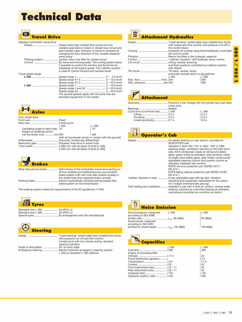
AttachmentFork Carrier and Fork
FEM III Fork Carrier and Forkwith Quick CouplerA Lifting height at max. reach mmC Max. lifting height mmE Max. operating height mmF Reach at loading position mmF max. Max. reach mmF min. Reach at max. lifting height mmG Fork length mmL Length – basic machine mm Tipping load, straight * kg Tipping load, articulated at 40° * kg Recommended payload for uneven ground = 60 % of tipping load, articulated 1) kg Recommended payload for smooth surfaces = 80 % of tipping load, articulated 1) kg Operating weight * kg Tyre sizes
* The figures shown here are valid with tyres above, includes all lubricants, a full fuel tank, the ROPS/FOPS cab and the operator. Different tyres and optional equipment will change the operating weight and tipping load. (Tipping load, articulated at 40° according to ISO 14397-1)
1) According to EN 474-32) Load capacity for the fork carrier and forks is limited to 5,000 kg
1,781 3,738 4,662 939
1,635 694
1,200 6,350 7,8806,940
3,825
5,000 2)
12,700 20.5R25 L3
L 5
38
L0003.01
E
C
500
F max
F min
A
G F
L
L550 - L580Picto Ladegabel14.03.2012

18 L 538 / L 556 / L 580
Technical Data
Engine L 556 L 580Diesel engine ����������������������� BF6M2012C Stage II: 6090HFL75
Stage IIIA: 6090HFL85 Design ������������������������� water-cooled, turbo charged, intercooled Cylinders inline ��������������� 6 6 Fuel injection process ������� Unit pump (PLD) electronic Common Rail
high-pressure injection Max. output according to DIN/ISO 3046 �������������kW 140 209 at RPM 2,500 1,600 Max. torque ���������������Nm 671 1,320 at RPM 1,500 1,400 Displacement ����������� litres 6.057 9.0 Bore/Stroke �������������� mm 101/126 118.4/136Air cleaner system ����������������� Dry air filter with main and safety element,
pre-cleaner, service indicatorElectrical system Operating voltage ���������� V 24 24 Battery ���������������������Ah 2 x 150 2 x 180 Alternator������������������V/A 28/80 28/100 Starter motor ���������� V/kW 24/4 24/7.8
L 556: available for exhaust emission limits of Stage II / Tier 2. L 580: selectable between models for exhaust standards of Stage II / Tier 2 and
Stage IIIA / Tier 3.
L0063
90 mm breit x 60 mm hoch
Out
put
(kW
)
To
rque
(Nm
)
rpm
L 580
00
200
400
600
800
1,000
1,200
1,400
2,000
1,600
1,800
25
50
75
100
125
150
175
250
200
225
800 1,000 1,200 1,400 1,600 1,800 2,000
Torque
Output
L580-1412-U-II-IIIAL0063 - 24.06.2013
L0069
90 mm breit x 60 mm hoch
Out
put
(kW
)
To
rque
(Nm
)
rpm
L 556
00
100
200
300
400
500
600
700
800
20
40
60
80
100
120
140
160
1,000 1,200 1,400 1,600 1,800 2,000 2,200 2,400 2,600
Torque
Output
L 556-1289-U-II (LMD)L0069 - 30.07.2013
L 5
56
/ L
58
0
L 538 / L 556 / L 580 19
Technical Data
Travel DriveStepless hydrostatic travel drive Design ������������������������� Swash plate type variable flow pump and two
variable axial piston motors in closed loop circuit and axle transfer case. Direction of travel is reversed by changing the flow-direction of the variable-displace-ment pump
Filtering system �������������� Suction return line filter for closed circuit Control ������������������������ By travel and inching pedal. The inching pedal makes
it possible to control the tractive and thrust forces steplessly at full engine speed. The Liebherr joystick is used to control forward and reverse travel
Travel speed range L 556 �������������������������� Speed range 1 ���������������������������� 0 – 4.0 km/h Speed range A1-2 ������������������������ 0 – 15.0 km/h Speed range A1-3 ������������������������ 0 – 40.0 km/h L 580 �������������������������� Speed range 1 ���������������������������� 0 – 10.0 km/h Speed range 2 and A2 ������������������� 0 – 20.0 km/h Speed range A3 �������������������������� 0 – 40.0 km/h The quoted speeds apply with the tyres that are
standard equipment on the loader
AxlesFour-wheel driveFront axle ��������������������������� FixedRear axle ���������������������������� Centre pivot
L 556 L 580 Oscillating angle to each side � 10° 13° Height of obstacles which can be driven over �������� mm 500 490
(with all fourwheels remain in contact with the ground)Differentials ������������������������� Automatic limited-slip differentialsReduction gear ��������������������� Planetary final drive in wheel hubsTrack width ������������������������� 2,090 mm with all types of tyres (L 556)
2,230 mm with all types of tyres (L 580)
BrakesWear-free service brake ����������� Self-locking of the hydrostatic travel drive (acting on
all four wheels) and additional pump-accumulator brake system with wet multi-disc brakes located in the wheel hubs (two seperate brake circuits)
Parking brake ���������������������� Electro-hydraulically actuated spring-loaded disc brake system on the transmission
The braking system meets the requirements of the EC guidelines 71/320.
TyresStandard size L 556 ��������������� 23.5R25 L3Standard size L 580 ��������������� 26.5R25 L3Special tyres ������������������������ By arrangement with the manufacturer
SteeringDesign ������������������������������ “Load-sensing” swash plate type variable flow pump
with pressure cut-off and flow control. Central pivot with two double-acting, damped steering cylinders
Angle of articulation ��������������� 40° (to each side)Emergency steering ��������������� Electro-hydraulic emergency steering system:
L 556 as standard / L 580 optional
Operator’s CabDesign ������������������������������ On elastic bearing on rear section, soundproof
ROPS/FOPS cab. Operator’s door with 110° (L 556) / 180° (L 580) opening angle, ventilation opening on the right hand side, front windscreen made of compound safety glass, green tinted as standard, side windows made of single-pane safety glass, grey tinted, continuously adjustable steering column and joystick control as standard, heatable rear window ROPS roll over protection per EN/ISO 3471/ EN 474-1 FOPS falling objects protection per EN/ISO 3449/ EN 474-1
Liebherr Operator’s seat ���������� 6 way adjustable seat with lap belt, vibration damping and suspension adjustable for the opera-tor’s weight (mechanically sprung)
Cab heating and ventilation ������� Operator’s cab with 4-level air control, cooling water heating, mechanical controlled heating as standard, mechanical controlled air-condition as option
Noise EmissionSound pressure, measured L 556 L 580according to ISO 6396 (inside cab): ������������������������� LpA 69 dB(A) 69 dB(A)Sound power, measured according to ISO 6395 (emitted by wheel loader): ���������� LWA 105 dB(A) 106 dB(A)
Capacities L 556 L 580Fuel tank ��������������������������� l 290 400Engine oil (including filter change) ���������������������������� l 17.5 34Pump distribution gearbox ������� l 2.5Transmission ���������������������� l 3.8 11.5Coolant ���������������������������� l 26 42Front axle/wheel hubs ������������ l 22 / 11 42 Rear axle/wheel hubs ������������� l 22 / 11 42 Hydraulic tank ��������������������� l 135 135Hydraulic system, total ����������� l 240 230
AttachmentGeometry ��������������������������� Powerful Z-bar linkage with tilt cylinder and cast steel
cross-tubeBearings ���������������������������� SealedCycle time at nominal load �������� L 556 L 580 Lifting �������������������������� 5.5 s 5.5 s Dumping ���������������������� 2.3 s 2.0 s Lowering (empty) ������������� 2.7 s 3.5 s
Attachment HydraulicsDesign ������������������������������ “Load-sensing” swash plate type variable flow pump
with output and flow control, and pressure cut-off in the control block
Cooling ����������������������������� Hydraulic oil cooling using thermostatically controlled fan and oil cooler
Filtration ���������������������������� Return line filter in the hydraulic reservoirControl ������������������������������ “Liebherr-Joystick” with hydraulic servo controlLift circuit ��������������������������� Lifting, neutral, lowering
and float positions controlled by Liebherr joystick with detent
Tilt circuit ��������������������������� Tilt back, neutral, dump automatic bucket return to dig optional L 556 L 580
Max. flow �������������������� l/min. 234 290Max. pressure ������������������bar 330 380 L
55
6 /
L 5
80

20 L 538 / L 556 / L 580
Loading Bucket L 556 L 580 STD HL STD HL Cutting tool Lift arm length mm Bucket capacity according to ISO 7546 ** m3
Bucket width mmA Dumping height at max. lift height and 45° discharge mmB Dump-over height mmC Max. height of bucket bottom mmD Max. height of bucket pivot point mmE Max. operating height mmF Reach at max. lift height and 45° discharge mmG Digging depth mmH Height above cab mm I Height above exhaust mmJ Ground clearance mmK Wheelbase mmL Overall length mm Turning circle radius over outside bucket edge mm Turning circle radius over tyres mm Width over tyres mm Breakout force (SAE) kN Tipping load, straight * kg Tipping load, articulated at 37° * kg Tipping load, articulated at 40° * kg Operating weight * kg Tyre sizes
* The figures shown here are valid with tyres above, includes all lubricants, a full fuel tank, the ROPS/FOPS cab and the operator. Different tyres and optional equipment will change the operating weight and tipping load. (Tipping load, articulated at 40° according to ISO 14397-1)
** Actual bucket capacity may be approx. 10 % larger than the calculation according to ISO 7546 standard. The degree to which the bucket can be filled depends on the material – see page 24.
= Excavation bucket with back grading edge for direct mounting
STD = Standard lift arm length HL = High Lift T = Welded-on tooth holder with add-on teeth
Dimensions
T T T T 2,750 3,050 3,050 3,250 3.5 3.0 5.0 4.5 2,900 2,900 3,300 3,000 3,200 3,700 3,320 3,530 3,810 4,230 4,100 4,300 3,950 4,320 4,270 4,470 4,230 4,650 4,580 4,780 5,730 6,100 6,340 6,540 1,000 850 1,150 1,215 60 80 100 140 3,380 3,380 3,590 3,590 2,800 2,800 3,000 3,000 500 500 535 535 3,280 3,280 3,900 3,900 8,365 8,670 9,645 9,915 6,560 6,790 7,910 7,895 5,853 5,850 7,150 7,150 2,740 2,740 2,960 2,960 130 125 190 190 14,620 12,880 20,780 18,990 13,140 11,580 18,380 16,760 12,900 11,380 18,000 16,400 17,400 17,560 24,720 25,030 23.5R25 L3 26.5R25 L3
L 5
56
/ L
58
0
L0023.01J
K
LG
49º
AB
CD
E
IH
F
65°
45°

L 538 / L 556 / L 580 21
AttachmentLight Material Bucket
Light Material Bucket L 556 L 580with Bolt-On Cutting Edge STD HL HL STD STD Bucket capacity m3
Bucket width mmA Dumping height at max. lift height mmE Max. operating height mmF Reach at maximum lift height mmL Overall length mm Tipping load, straight * kg Tipping load, articulated at 40° * kg Operating weight * kg Tyre sizes
* The figures shown here are valid with tyres above, includes all lubricants, a full fuel tank, the ROPS/FOPS cab and the operator. Different tyres and optional equipment will change the operating weight and tipping load. (Tipping load, articulated at 40° according to ISO 14397-1)
STD = Standard lift arm length HL = High Lift
4.5 3.5 4.5 6.5 8.0 2,900 2,900 2,900 3,200 3,500 2,980 3,650 3,400 3,195 3,150 5,880 6,150 6,300 6,450 6,480 1,160 900 1,100 1,205 1,240 8,430 8,770 9,020 9,510 9,600 13,970 12,834 12,384 20,130 18,210 12,330 11,324 10,926 17,390 15,970 17,790 17,610 17,973 24,960 25,420 23.5R25 L3 26.5R25 L3
L 5
56
/ L
58
0
L0024.01
A
E
F
L

22 L 538 / L 556 / L 580
AttachmentHigh-Dump Bucket
High-Dump Bucket L 580with Bolt-On Cutting Edge STD Bucket capacity m3
Bucket width mmA Dumping height at max. lift height mmE Max. operating height mmF Reach at maximum lift height mmL Overall length mm Tipping load, straight * kg Tipping load, articulated at 40° * kg Operating weight * kg Tyre sizes
* The figures shown here are valid with tyres above, includes all lubricants, a full fuel tank, the ROPS/FOPS cab and the operator. Different tyres and optional equipment will change the operating weight and tipping load. (Tipping load, articulated at 40° according to ISO 14397-1)
STD = Standard lift arm length
6.53,2005,0507,4501,4309,98018,15015,50026,180
26.5R25 L3
L 5
80
L0006.01
E
AF
L
L 538 / L 556 / L 580 23
AttachmentFork Carrier and Fork
FEM IV Fork Carrier and Fork L 556with Quick Coupler STDA Lifting height at max. reach mmC Max. lifting height mmE Max. operating height mmF Reach at loading position mmF max. Max. reach mmF min. Reach at max. lifting height mmG Fork length mmL Length – basic machine mm Tipping load, straight * kg Tipping load, articulated at 40° * kg Recommended payload for uneven ground = 60 % of tipping load, articulated 1) kg Recommended payload for smooth surfaces = 80 % of tipping load, articulated 1) kg Operating weight * kg Tyre sizes
* The figures shown here are valid with tyres above, includes all lubricants, a full fuel tank, the ROPS/FOPS cab and the operator. Different tyres and optional equipment will change the operating weight and tipping load. (Tipping load, articulated at 40° according to ISO 14397-1)
1) According to EN 474-32) Payload on forks is limited by tilt cylinder
STD = Standard lift arm length
1,8334,0104,9951,0921,728682
1,5007,34610,2409,030
5,418
6,500 2)
17,14023.5R25 L3
L550 - L580Picto Ladegabel14.03.2012
L 5
56
L0025.01
600
A
C
E
LFG
F max.
F min.

24 L 538 / L 556 / L 580
Bucket selection
Bulk Materials
Bucket Filling Factor
Lift armZK Z-bar linkage, standard lift arm lengthZK-HL Z-bar linkage, High LiftZK-QH Z-bar linkage, including quick-hitch, standard lift arm length
BucketGPB General purpose bucket (Excavation)LMB Light material bucketHDB High-dump bucket
Bulk Material Densities and Bucket Filling Factors t/m3 %Gravel, moist 1.9 105 dry 1.6 105 crushed stone 1.5 100Sand, dry 1.5 105 wet 1.9 110Gravel and sand, dry 1.7 105 wet 2.0 100Sand / clay 1.6 110Clay, natural 1.6 110 dry 1.4 110Clay / gravel, dry 1.4 110 wet 1.6 100
t/m3 %Earth, dry 1.3 115 wet excavated 1.6 110Topsoil 1.1 110Basalt 1.95 100Granite 1.8 95Sandstone 1.6 100Slate 1.75 100Bauxite 1.4 100Limestone 1.6 100Gypsum, broken 1.8 100Coke 0.5 110Slag, broken 1.8 100
t/m3 %Glass waste, broken 1.4 100 solid 1.0 100Compost, dry 0.8 105 wet 1.0 110Wood chips / saw dust 0.5 110Paper, shredded / loose 0.6 110 recovered paper / cardboard 1.0 110Coal, heavy material density 1.2 110 light material density 0.9 110Waste, domestic waste 0.5 100 bulky waste 1.0 100
L 538
Tabellenbreite 90 mm
L 538 für NTB_L538-L550-L580NTB_L538-L556-L580
Liftarm
BucketMaterial density (t/m³)
0.4 0.6 0.8 1.0 1.2 1.4 1.6 1.8 2.0
ZK
GPB2.5 m³
2.7 m³
LMB3.5 m³
4.0 m³
ZK-
QH GPB 2.2 m³
2.8
3.9
4.4
2.4
2.7
2.5
3.5
4.0
2.2
100 % 95 %105 %110 %
Schaufelfüllung
L 580Tabellenbreite 90 mm
L 580 für NTB_L538-L550-L580NTB_L538-L556-L580
Liftarm
BucketMaterial density (t/m³)
0.4 0.6 0.8 1.0 1.2 1.4 1.6 1.8 2.0
ZK
GPB 5.0 m³
LMB6.5 m³
8.0 m³
HDB 6.5 m³
ZK-
HL GPB 4.5 m³
5.5
7.2
5.0
8.8
7.2
5.0
6.5
4.5
8.0
6.5
100 % 95 %105 %110 %
Schaufelfüllung
L 556
Tabellenbreite 90 mm
L 556 für NTB_L538-L556-L580
Liftarm
BucketMaterial density (t/m³)
0.4 0.6 0.8 1.0 1.2 1.4 1.6 1.8 2.0
ZK
GPB 3.5 m³
LMB 4.5 m³
ZK-H
L
GPB 3.0 m³
LMB3.5 m³
4.5 m³
3.9
3.3
5.0
5.0
3.9
3.5
3.0
4.5
4.5
3.5
100 % 95 %105 %110 %
Schaufelfüllung
Tabellenbreite 90 mm
L 556 für NTB_L538-L556-L580
Liftarm
BucketMaterial density (t/m³)
0.4 0.6 0.8 1.0 1.2 1.4 1.6 1.8 2.0
ZK
GPB 3.5 m³
LMB 4.5 m³
ZK-H
L
GPB 3.0 m³
LMB3.5 m³
4.5 m³
3.9
3.3
5.0
5.0
3.9
3.5
3.0
4.5
4.5
3.5
100 % 95 %105 %110 %
Schaufelfüllung
L 538 / L 556 / L 580 25
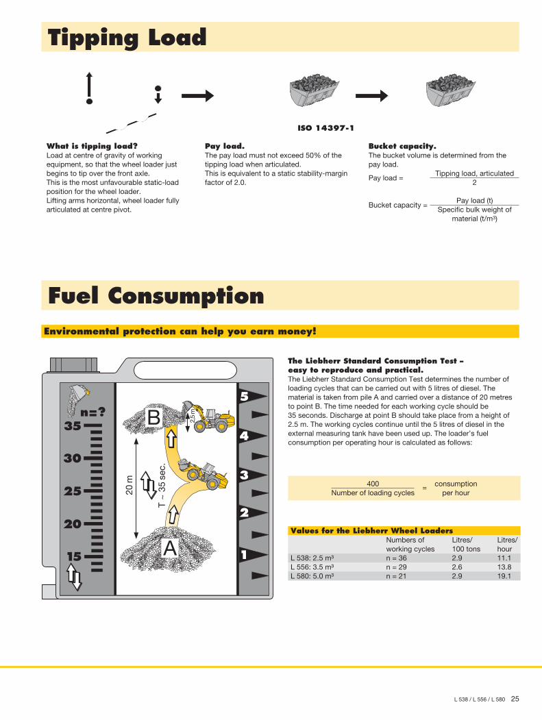
Tipping Load
Fuel Consumption
What is tipping load?Load at centre of gravity of working equipment, so that the wheel loader just begins to tip over the front axle.This is the most unfavourable static-load posi tion for the wheel loader.Lifting arms horizontal, wheel loader fully articulated at centre pivot.
Pay load.The pay load must not exceed 50% of the tipping load when articulated.This is equivalent to a static stability-margin factor of 2.0.
Bucket capacity.The bucket volume is determined from the pay load.
Tipping load, articulated2
Pay load =
Pay load (t)Specific bulk weight of
material (t/m3)
Bucket capacity =
ISO 14397-1
Environmental protection can help you earn money!
2
5
4
3
115
20
25
30
35n=?
T ~
35
sec.
A
B
20m
2,5
m
The Liebherr Standard Consumption Test –easy to reproduce and practical.The Liebherr Standard Consumption Test determines the number of loading cycles that can be carried out with 5 litres of diesel. The mate rial is taken from pile A and carried over a distance of 20 metres to point B. The time needed for each working cycle should be 35 seconds. Discharge at point B should take place from a height of 2.5 m. The working cycles continue until the 5 litres of diesel in the external measuring tank have been used up. The loader’s fuel consumption per operating hour is calculated as follows:
400Number of loading cycles
= consumption per hour
Values for the Liebherr Wheel Loaders Numbers of Litres/ Litres/ working cycles 100 tons hourL 538: 2.5 m³ n = 36 2.9 11.1L 556: 3.5 m³ n = 29 2.6 13.8L 580: 5.0 m³ n = 21 2.9 19.1

• = Standard, + = Option, – = not available
Equipment
Basic MachineAutomatic central lubrication system + + +Battery master switch • • •Automatic travel mode • • •Speed range selection • • •Ride control + + +Parking brake • • •Speed limiting Vmax • • •Pre-heat system for cold starting • • •Combined inching-braking system • • •Multi-disc limited slip differentials in both axles • • •Air cleaner system with pre-filter • • •Emergency steering system + • +Acoustic back-up alarm • • •Tail lights • • •Headlights and license plate illumination rear, single version (on tail flap) – halogen
+
+ +
Headlights front, single version (on front-chassis) – halogen • • •Lockable doors, service flap and engine hood • • •Ramming guard + + +Chock + + +Air pre-cleaner + + +Fuel pre-heating system + + +Hazard warning flashers • • •Toolbox with toolkit • • •Central lubrication lines for lift arm + + •Towing hitch • • •
EquipmentWorking hydraulics lockout • • •Automatic bucket return to dig – adjustable • • •Fork carrier and lift forks + + –High Lift arms – + +High-dump bucket – – +Hydraulic quick coupler + + +Hydraulic servo control of working hydraulics • • •Tilt cylinder protection – + + Loading buckets with and without teeth, or bolt-on cutting edge + + +Country-specific versions + + +Light material bucket + + +Float position • • •Z-bar linkage • • •3rd hydraulic control circuit + + +3rd and 4th hydraulic control circuits – + – L
538
/ L 5
56 /
L 58
0 05
.13
Audible Warnings forQuick coupler, opened • • •Coolant level • • •Charge air / fuel temperature too high • • •Steering system / braking system • • •Engine oil pressure • • •Service codes • • •Overheating of coolant, fuel, hydraulic oil or gearbox oil • • •Acoustic back-up alarm • • •
Warning symbols forBattery charge • • •Brake accumulator pressure • • •Emergency steering system + • +Air cleaner blockage • • •Engine oil pressure • • •Engine overheat • • •Operator’s Cab
Storage box • • •Armrest, adjustable • • •Exterior mirror, heatable + + +Exterior mirror, tiltable • • •Operator’s seat – mechanically sprung • • •Operator’s seat – air sprung + + +Operator’s seat – air sprung with seat heating + + +Fire extinguisher 2 kg + + +Cup holder • • •Rear window heater • • •Heater • • •Horn • • •Floor mat • • •Clothes hook • • •Air conditioning system • • •Storage box with cooling function + + +Steering column, height-adjustable + + +Steering column, adjustable • • • Liebherr joystick control – adjustable • • •Radio • • •Provision for radio including loudspeaker + + +Interior rear-view mirror • • •Amber beacon + + +Soundproof ROPS/FOPS cab • • •Wash/wipe system for windscreen and rear window • • •Headlights rear, double version – halogen + + +Headlights rear, single version – halogen • • •Headlights front, double version – halogen • • •Windscreen guard + + +Sun visor front • • •Sunblind front / rear + + +Dust filter system + + +Plug 12 V • • •First aid kit + + +Wide angle mirror + + +
Display unitWorking hydraulics lockout • • •Battery charge • • •Timer for hours of operation • • •Indicator light / Hazard warning lights • • •Brake accumulator pressure • • •Rev. Counter • • •Speed range indicator • • •Travel speed • • •Travel direction • • •Parking brake • • •Gear level • • •Hydraulic oil temperature (overheating) • • •Fuel level • • •Coolant temperature • • •Engine oil pressure • • •Emergency steering system + • +Service codes • • •System and function settings • • •Time • • •Tractive force regulation – – •
Liebherr-Werk Bischofshofen GmbH Postfach 49, A-5500 Bischofshofen +43 50809 1-0, Fax +43 50809 11385 www.liebherr.com, E-Mail: [email protected] www.facebook.com/LiebherrConstruction
Liebherr Machinery (Dalian) Co., Ltd. No. 30, Wanli Street, Dalian Dev. Zone, Dalian 116600 +86 411 8733 5999, Fax +86 411 8733 5881 www.liebherr.com, E-Mail: [email protected] www.facebook.com/LiebherrConstruction
Prin
ted
in C
hina
R
G-B
K L
BH
/PM
11
1606
74-3
-01.
14_e
nGB
A
ll ill
ustr
atio
ns a
nd d
ata
may
diff
er fr
om s
tand
ard
eq
uip
men
t. S
ubje
ct t
o ch
ange
with
out
notic
e.
53
8
55
6
58
0
53
8
55
6
58
0
53
8
55
6
58
0
53
8
55
6
58
0
53
8
55
6
58
0
53
8
55
6
58
0
![Tier 3/Stage III Auploads.gocdn.us/52/1/Tier3_pamphlet dswt18[1].pdf · compliance is available with John Deere engines. To meet Tier 3/Stage III A standards, John Deere worked closely](https://img.pdfslide.net/doc/110x75/61297dbc1d2a2e55fd42f195/tier-3stage-iii-dswt181pdf-compliance-is-available-with-john-deere-engines.jpg)


![Interim Tier 4/Stage III B frequently asked questionsbellpower.com/uploads/product_brochures/4_IT4_FAQ[1].pdf · Interim Tier 4/Stage III B frequently asked questions Updated March](https://img.pdfslide.net/doc/110x75/5b3447f27f8b9a436d8bd2ee/interim-tier-4stage-iii-b-frequently-asked-1pdf-interim-tier-4stage-iii.jpg)