Embed Size (px)
Citation preview
8/12/2019 Stage-nguyen Huu Nghia
http://slidepdf.com/reader/full/stage-nguyen-huu-nghia 1/90
Institut de la Francophonie pour
l'Informatique
Institut Eurécom
Mémoire de fin d’études
Intégration du protocole MBMS dans la
plateforme TD-CDMA
Réalisé par :
NGUYEN Huu Nghia
Promotion 9 – IFI
Sous la responsabilité de :
Mme Michelle WETTERWALD
Ingénieur de recherche senior à l’institut Eurécom
Sophia Antipolis, Le 20 octobre
8/12/2019 Stage-nguyen Huu Nghia
http://slidepdf.com/reader/full/stage-nguyen-huu-nghia 2/90
Table des matières
Table des matières .......................................................................................................................2
Liste des figures...........................................................................................................................5
Liste des tableaux ........................................................................................................................6
Remerciements ............................................................................................................................7
Résumé ........................................................................................................................................8
Abstract........................................................................................................................................9
CHAPITRE 1 - INTRODUCTION...........................................................................................10
1. Problématique..............................................................................................................10
2. Motivation ...................................................................................................................11
3. Contribution.................................................................................................................12
4. Environnement de stage ..............................................................................................12
CHAPITRE 2 – ETAT DE L’ART ...........................................................................................13
1. UMTS - Les réseaux mobiles 3G ................................................................................13
1.1. Historique..................................................................................................................13
1.2. Architecture générale du réseau UMTS....................................................................14
1.3. Le contexte international - Recherche et normalisation pour la 3G..........................15
2. Broadcast Multicast .....................................................................................................16
2.1. Généralité .............................................................................................................. 16
2.2. Le protocole 3GPP MBMS ...................................................................................17
3. Projet Daidalos ............................................................................................................ 20
2
8/12/2019 Stage-nguyen Huu Nghia
http://slidepdf.com/reader/full/stage-nguyen-huu-nghia 3/90
3.1. Une perspective pour les réseaux post 3G.............................................................20
3.2. Broadcast et Multicast dans le contexte du projet Daidalos..................................21
4. Plate-forme TD-CDMA ..............................................................................................22
CHAPITRE 3 – VERS UNE PLATEFORME TD-CDMA MULTICAST ..............................25
1. Description ..................................................................................................................25
2. Adaptation du MBMS pour Daidalos..........................................................................28
3. Mise en œuvre ............................................................................................................. 32
3.1. Préparation pour une couche RRC multicast.........................................................32
3.2. Mise en œuvre du RRC-RG ..................................................................................33
3.2.1. Initialisation.......................................................................................................33
3.2.2. Le séquenceur....................................................................................................33
3.2.3. Les signaux de sortie .........................................................................................34
3.2.4. Simulation ......................................................................................................... 34
3.2.5. Interaction avec le NAS ....................................................................................35
3.2.6. Interaction avec le serveur RRM.......................................................................38
3.3. Mise en œuvre du RRC-UE...................................................................................38
3.3.1. Initialisation.......................................................................................................38
3.3.2. Traitement des messages MBMS sur le canal MCCH......................................39
3.3.3. Traitement des messages MBMS sur le canal DCCH.......................................39
3.3.4. La machine à états finis.....................................................................................39
CHAPITRE 4 – EVALUATION...............................................................................................41
1. Critères d’évaluation ...................................................................................................41
2. Banc de test .................................................................................................................41
3

8/12/2019 Stage-nguyen Huu Nghia
http://slidepdf.com/reader/full/stage-nguyen-huu-nghia 4/90
8/12/2019 Stage-nguyen Huu Nghia
http://slidepdf.com/reader/full/stage-nguyen-huu-nghia 5/90
Liste des figures
FIGURE 1. L’EVOLUTION DES RESEAUX DE TELECOMMUNICATION .........................................................................14
FIGURE 2. ARCHITECTURE DU RESEAU UMTS .......................................................................................................15
FIGURE 3. ARCHITECTURE LOGIQUE DU MBMS......................................................................................................18
FIGURE 4. PHASES D'UN SERVICE MBMS BROADCAST ............................................................................................18
FIGURE 5. PHASES D'UN SERVICE MBMS MULTICAST ............................................................................................19
FIGURE 6. U NE ILLUSTRATION EXEMPLAIRE DE LA RECEPTION D'UN SERVICE MBMS MULTICAST .........................20
FIGURE 7. I NTEGRATION DE BROADCAST/MULTICAST DANS DAIDALOS ..................................................................21
FIGURE 8. EVOLUTION DU STANDARD 3GPP VERS PURE-IPV6 ................................................................................22
FIGURE 9. LA PILE PROTOCOLAIRE ..........................................................................................................................23
FIGURE 10. LES COMPOSANTS LOGICIELS DE LA PLATEFORME ................................................................................24
FIGURE 11. LA PLANIFICATION GENERALE ..............................................................................................................26
FIGURE 12. LA PLANIFICATION DE LA PREMIERE PHASE ..........................................................................................27
FIGURE 13. LA PLANIFICATION DE LA DEUXIEME PHASE .........................................................................................28
FIGURE 14. U NE ADAPTATION DU MBMS POUR DAIDALOS.................................................................................29
FIGURE 15. LES PRIMITIVES D’UN SERVICE DANS LE MODE CONNECTION................................................................31
FIGURE 16. DIAGRAMME DES CLASSES : LES PRIMITIVES DES SERVICES MMBS DE LA COUCHE RRC ....................32
FIGURE 17. DIAGRAMME DE SEQUENCE: ETABLISSEMENT D’UN PTM RB................................................................36
FIGURE 18. DIAGRAMME DE SEQUENCE: R ELACHEMENT D’UN PTM RB..................................................................37
FIGURE 19. R ESULTAT DU TEST AU MODE NATIF .....................................................................................................45
FIGURE 20. R ESULTAT DU TEST AU MODE D’INTEGRATION - SIMULATION...............................................................46
5

8/12/2019 Stage-nguyen Huu Nghia
http://slidepdf.com/reader/full/stage-nguyen-huu-nghia 6/90
Liste des tableaux
TABLEAU 1 : ORGANISMES REGIONAUX PARTICIPENT AU 3GPP ............................................................................. 16
TABLEAU 2: PROTOCOLS BROADCAST ET MULTICAST .............................................................................................17
TABLEAU 3: R EACTIONS DU UE POUR LA PROCEDURE JOIN....................................................................................30
TABLEAU 4: R EACTIONS DU UE POUR LA PROCEDURE LEAVE ................................................................................30
TABLEAU 5: BANC DE TEST ..................................................................................................................................... 42
TABLEAU 6: SCÉNARIO DE TEST ..............................................................................................................................42
TABLEAU 7: R ESULTATS ESPERES COTE RG............................................................................................................ 43
TABLEAU 8: R ESULTATS ESPERES COTE UE............................................................................................................44
6
8/12/2019 Stage-nguyen Huu Nghia
http://slidepdf.com/reader/full/stage-nguyen-huu-nghia 7/90
Remerciements
En premier lieu, je tiens à exprimer ma plus grande reconnaissance envers ma
responsable de stage, Madame Michelle WETTERWALD qui a accepté de m'accueillir en
stage avec son équipe de recherche pour m'avoir permis de mener à bien ce travail par ses
conseils, ses remarques et ses suggestions. Je la remercie aussi pour son soutien,
l’encouragement qu'elle m'a donné pour faciliter mes conditions de vie à Sophia, pour me
familiariser avec la vie de l'équipe.
Je tiens à remercier Monsieur Christian BONNET, Directeur de l’unité
Communications Mobiles de l’Eurécom, pour son encouragement et sa sympathie pendantmon stage.
Je tiens à exprimer toute ma reconnaissance à Monsieur HO Tuong Vinh, Directeur
d’études de l’IFI (Institut de la Francophonie pour l’Informatique), d’avoir préparé mon stage.
Je remercie aussi vivement Monsieur Charles Durand, Directeur de l’IFI, de m’avoir
bien favorisé au cours de mon stage.
Je remercie tous les membres de l’unité Communications Mobiles pour leurs
encouragements, leurs conseils, leurs aides et la sympathie qu'ils m'ont donnée.
Depuis le début de mon stage en France, j'ai reçu beaucoup d'aides et
d'encouragements de mes amis. Tout cela me permet de mieux compléter le stage. Je les
remercie.
Je voudrais également remercier mes parents et ma sœur qui m'encouragent
énormément depuis le début de mon stage en France.
Enfin, un grand merci à toutes les personnes de l’Institut Eurécom et de l’IFI dem’avoir aidé au cours de mon stage.
7
8/12/2019 Stage-nguyen Huu Nghia
http://slidepdf.com/reader/full/stage-nguyen-huu-nghia 8/90
Résumé
La nouvelle génération de réseaux post 3G doit intégrer tous les réseaux existants,
c'est-à-dire les réseaux de données de type Internet, les réseaux téléphoniques, que ce soit le
réseau téléphonique commuté ou le réseau cœur d’un opérateur de mobiles, et les réseaux de
vidéo pour effectuer de la diffusion de télévision ou de la vidéo à la demande. En ce qui
concerne le broadcast et le multicast, pour les réseaux de télécommunication UMTS
(Universal Mobile Telecommunications System) où les ressource radio et les ressources du
réseau de cœur sont vraiment limitées, on doit recourir au protocole MBMS (Multimedia
Broadcast Multicast Service) normalisé par le 3GPP (3rd Generation Partnership Project). Ce
rapport vise à présenter l’intégration et les expérimentations du protocole MBMS dans la platforme TD-CDMA (Time Division – Code Division Multiple Access) d’Eurécom dans le
cadre du projet DAIDALOS (Designing Advanced network Interfaces for the Delivery and
Administration of Location independent, Optimised personal Services ).
Le rapport se compose de 4 chapitres et 4 annexes.
D’abord, le chapitre 1 présente le problème du Broadcast et du Multicast dans
DAIDALOS et l’environnement du stage.
Ensuite, dans le chapitre 2, un état de l’art dans le domaine d’étude sera présenté. Le chapitre 3 présentera les démarches à faire pour produire une couche RRC (Radio
Resource Control) multicast dans la plateforme TD-CDMA avec des adaptations
nécessaires au protocole MBMS.
Et puis, le chapitre 4 donne une évaluation sur l’intégration et les expérimentations sur ces
adaptations.
L’annexe A vous montrera des termes et des abréviations.
L’annexe B représentera la machine à états finis côté UE (User Equipment) modélisé avec
Télélogic Tau
L’annexe C est le document de spécification du protocole MBMS synthétisé à l’Eurécom
L’annexe D est le document de conception .
Mot clés: B3G, Broadcast, Daidalos, Multicast, MBMS, TD-CDMA, UMTS, 3GPP
8
8/12/2019 Stage-nguyen Huu Nghia
http://slidepdf.com/reader/full/stage-nguyen-huu-nghia 9/90
Abstract
The new B3G network must integrate all existing networks: Enterprises, Multimedia
and Telecommunications. In regard to Broadcast and Multicast in the UMTS (Universal
Mobile Telecommunications System) telecommunications network where the radio resources
and network resources are really limited, we have to use the MBMS (Multimedia Broadcast
Multicast Service) protocol, which is standardized by the 3GPP (3rd Generation Partnership
Project). This report aims to present the integration and the experimentations of MBMS
protocol in the Eurecom’s TD-CDMA (Time Division – Code Division Multiple Access)
platform within the scope of DAIDALOS project (Designing Advanced network Interfaces forthe Delivery and Administration of Location independent, Optimised personal Services ).
This report is composed with 4 chapters and 4 appendixes
First of all, the chapter 1 presents the broadcast and multicast problems in DAIDALOS
project and the working environment.
In the chapter 2, A state of the art in the domain will be presented
The chapter 3 presents the process to product a RRC (Radio Resource Control) multicast
layer in the TD-CDMA platform with necessary adaptations to the MBMS protocol. The chapter 4 gives an evaluation on the integration and experimentations on the
adaptations.
The appendix A presents a list of terms and abbreviations used in the report
The appendix B presents the UE’s finite state machine modeled with Telelogic Tau
The appendix C is the Eurecom's specification document of the MBMS protocol
The appendix D is the Eurecom's design document.
Key words: B3G, Broadcast, Daidalos, Multicast, MBMS, TD-CDMA, UMTS, 3GPP
9
8/12/2019 Stage-nguyen Huu Nghia
http://slidepdf.com/reader/full/stage-nguyen-huu-nghia 10/90
1
Chapitre
CHAPITRE 1 - INTRODUCTION
1. Problématique
Le réseau sans fil de troisième génération (3G), fournit une bande passante plus élevée,
un accès à l’internet à plus haute vitesse. Cela favorise énormément des services multimédias.
Au fur et à mesure que les technologies et la société changent, il y a une prolifération detechnologies et de services pour les utilisateurs mobiles. Cela crée un environnement de
communications complexe non seulement pour les utilisateurs mais également pour les
opérateurs.
DAIDALOS est un Projet Intégré dans le cadre du FP6 (6th Framework Program)
lancé au niveau européen et regroupe un grand nombre de partenaires. Il s’adresse aux
problèmes d'hétérogénéité des accès. Pour le multicast, par exemple, on doit assurer une
diffusion de contenu multimédia sans interruption et indépendante du type de réseau – que ce
soit un réseau de diffusion, un réseau de télécommunication ou un réseau sans fil d’entreprise.
Parmi ses 46 partenaires industriels et académiques, Eurécom joue un rôle actif pour
remplir les objectifs avec la plateforme radio logicielle TD-CDMA qui est développée au sein
du département Communications Mobiles. L'utilisation d’une technologie de radio logicielle
permet de conserver des coûts d’équipements raisonnables, car principalement basés sur des
équipements peu chers tels que des micro-ordinateurs PC. D’autre part, cela fournit un moyen
idéal pour mener des expérimentations en vraie grandeur d’un système radio mobile. Enfin,
ces plateformes sont utilisées pour valider des avancées théoriques, en particulier dans le
domaine très prometteur des réseaux sans fil post 3G [35].
A l’heure actuelle, la plateforme TD-CDMA reste encore un système unicast conforme
à la norme 3GPP R4 [2]. Dans un système unicast, il s’agit des connexions de type point à
point entre le client et le serveur. Avec une augmentation des applications consommant
énormément de bande passante radio, et particulièrement, avec un grand nombre d’utilisateurs
recevant le même service à haut taux de données, la distribution d'information efficace devient
10
8/12/2019 Stage-nguyen Huu Nghia
http://slidepdf.com/reader/full/stage-nguyen-huu-nghia 11/90
essentielle.
Pour résoudre ce problème, le Broadcast/Multicast est utilisé pour communiquer
simultanément avec un groupe de terminaux identifiés par une adresse spécifique. L'avantage
de ce principe par rapport à l’unicast classique devient évident quand on veut diffuser de la
vidéo. Le paquet n'est émis qu'une seule fois, et sera routé vers toutes les machines du groupede diffusion. Cela assure une économie des ressources radio très pertinente dans les systèmes
mobiles [33].
Pour les réseaux locaux sans fils d’entreprise, on utilise IP Multicast de l’IETF commesolution. Pourtant dans un réseau de télécommunication où les ressources radio sont vraiment
limitées, ce protocole ne conviendra pas comme il consommera encore énormément de bande
passante ainsi que l’énergie pour la signalisation.
Le protocole MBMS (Multimédia Broadcast Multicast Service) conçu par le 3GPP, pour les systèmes mobiles 3G, utilise la même philosophie « one to many » et est dédié aux
réseaux de télécommunications mobiles. Ce n’est donc pas étonnant qu’il faille intégrer le
protocole MBMS dans la plate-forme afin d’optimiser l’usage des ressources radio, de se
conformer à l’évolution de la norme 3GPP R6 (Release 6) et de satisfaire aux objectifs initiaux
de la plateforme et aux exigences du projet Daidalos.
La plateforme TD-CDMA est construite sur l’idée d’une architecture « Pure-IP » [1]
pour conserver des coûts d’équipements en tenant compte du but « All-IP » [7] des réseaux
post 3G. Il reste donc une question sur l’adaptation optimisée du protocole MBMS à la
plateforme. De plus, ce protocole est en voie de normalisation, et il faut également des
expérimentations pour valider la stabilité du protocole.
Dans le cadre du stage, j’étendrai la couche RRC de la plateforme TD-CDMA et la
rendra RRC-multicast conformant à la norme 3GPP R6 [11, 12, 13, 14, 15, 16, 17, 18, 19, 20,
21, 22, 37].
2. Motivation
En choisissant le sujet, j’aurai une chance de contacter avec de grandes partenaires du projet Daidalos. D’ailleurs, MBMS est actuellement un sujet à la pointe de la technologie. En
plus, je bénéficierai d’une formation au métier de recherche et de développement. J’ai pu
acquérir des méthodes de travail ainsi qu’une expérience de recherche grâce aux responsables
de stage et les collèges dans l'équipe. Enfin, je me suis habitué au processus d’une
normalisation d’un protocole.
11
8/12/2019 Stage-nguyen Huu Nghia
http://slidepdf.com/reader/full/stage-nguyen-huu-nghia 12/90
3. Contribution
Ce document est le fruit de 7 mois de travail. Pendant ce temps, j’ai accompli toutes les
tâches concernant non seulement la partie théorique mais aussi la partie pratique.
Sur le plan théorique, j’ai maîtrisé le protocole MBMS et la couche RRC de
l’architecture UMTS. En plus, j’ai aussi suivi les compte-rendus des réunions du 3GPP sur le
protocole MBMS pour l’adapter aux exigences du projet DAIDALOS sous la direction de
madame Michelle Wetterwald. J’ai aussi synthétisé toutes les informations dans les documents
du 3GPP concernant le protocole MBMS de la couche RRC dans un document de
spécification d’Eurécom. Nous avons discuté pour archiver une adaptation optimale au
protocole MBMS, pour prévoir l’interaction entre les composants de la plate-forme TD-
CDMA.
Sur le plan pratique, j’ai implémenté le protocole MBMS qui peut fonctionner dans lemode natif (pour le test) ou dans le mode d’intégration (pour le projet DAIDALOS). Les
adaptations sont bien réalisées et validées.
4. Environnement de stage
Le stage se déroule pendant 7 mois (à partir du 21 mars 2005) à l’Institut Eurécom,
Sophia Antipolis, FRANCE. Le Parc scientifique de Sophia Antipolis s'affirme aujourd'hui
comme le pôle d'excellence européen dans le domaine des hautes technologies. C'est
aujourd'hui le site le plus convoité, notamment par les entreprises du secteur des technologiesde l'information. Quant à Eurécom, c’est une Grande Ecole internationale d’Ingénieurs et un
Centre de Recherche en Systèmes de communication, fondée par Télécom Paris (Ecole
Nationale Supérieure des Télécommunications) et l'EPFL (Ecole Polytechnique Fédérale de
Lausanne).
Ce travail est réalisé sous la direction de Mme Michelle WETTERWALD à l’unité
Communications Mobiles qui est actuellement dirigée par M. le professeur Christian
BONNET. Les travaux de l’unité portent sur différents aspects d'un réseau Mobile. Les axes
de Recherche du Département se déclinent dans plusieurs environnements:
Les réseaux mobiles de troisième génération et au delà Les réseaux locaux sans fil Les réseaux de communication à courte portée (Capteurs) Les réseaux Ad Hoc
Des informations plus détaillées sur l'équipe se trouvent dans son site
web http://www.eurecom.fr/cm.fr.htm
12
8/12/2019 Stage-nguyen Huu Nghia
http://slidepdf.com/reader/full/stage-nguyen-huu-nghia 13/90
Chapitre
2CHAPITRE 2 – ETAT DE L’ART
Ce chapitre est consacré à un état de l’art dans le domaine d’étude. Un survol sur les
réseaux mobiles 3G, les technologies différentes pour la diffusion, et enfin, le projet Daidalos
avec la convergence des réseaux mobiles ainsi que la plateforme TD-CDMA seront présentés.
On considère dans ce rapport que les connaissances de base des réseaux sans fil informatiques,des réseaux sans fil de télécommunication sont connues par le lecteur. Pour en savoir plus,
voir [7, 8, 18, 19, 29].
1. UMTS - Les réseaux mobiles 3G
1.1. Historique
Les réseaux cellulaires analogiques ont été communément appelés “systèmes de
première génération”. Quant aux réseaux numériques utilisés à l’heure actuelle, comme leGSM (Global System for Mobile Communications), le PDC (Personal Digital Cellular), le
CdmaOne (IS-95) et l’US-TDMA (IS-136), ils sont regroupés sous l’appellation de «système
de deuxième génération ». Ces systèmes ont permis aux communications vocales de
s’affranchir de la traditionnelle paire de cuivre et de gérer efficacement la mobilité de leurs
utilisateurs.
La deuxième génération est maintenant parfaitement implantée dans de nombreux
pays, et la troisième est en cours de mise en place. Cependant, cette mise en place va
demander un laps de temps assez long à l’aide des réseaux de génération deux et demie. Les
raisons à cela sont d’une part, le besoin de repartir de zéro du point de vue des infrastructureset, d’autre part, un manque de capitaux de la part des opérateurs de mobiles à la suite de
l’achat de licences [8]. Les réseaux de génération 2,5 se caractérisent souvent, comme c’est le
cas dans le GPRS (General Packet Radio Service), par un double réseau cœur, un réseau cœur
pour le transport du téléphone et un réseau cœur pour le transport des données sous forme de
paquets.
13
8/12/2019 Stage-nguyen Huu Nghia
http://slidepdf.com/reader/full/stage-nguyen-huu-nghia 14/90
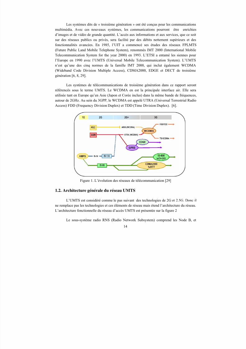
Les systèmes dits de « troisième génération » ont été conçus pour les communications
multimédia. Avec ces nouveaux systèmes, les communications pourront être enrichies
d’images et de vidéo de grande quantité. L’accès aux informations et aux services, que ce soit
sur des réseaux publics ou privés, sera facilité par des débits nettement supérieurs et des
fonctionnalités avancées. En 1985, l’UIT a commencé ses études des réseaux FPLMTS
(Future Public Land Mobile Telephone System), renommés IMT 2000 (International Mobile
Telecommunication System for the year 2000) en 1993. L’ETSI a entamé les siennes pour
l’Europe en 1990 avec l’UMTS (Universal Mobile Telecommunication System). L’UMTS
n’est qu’une des cinq normes de la famille IMT 2000, qui inclut également WCDMA
(Wideband Code Division Multiple Access), CDMA2000, EDGE et DECT de troisième
génération [6, 8, 29].
Les systèmes de télécommunications de troisième génération dans ce rapport seront
référencés sous le terme UMTS. Le WCDMA en est la principale interface air. Elle sera
utilisée tant en Europe qu’en Asie (Japon et Corée inclus) dans la même bande de fréquences,autour de 2GHz. Au sein du 3GPP, le WCDMA est appelé UTRA (Universal Terrestrial Radio
Access) FDD (Frequency Division Duplex) et TDD (Time Division Duplex). [6].
Figure 1. L’évolution des réseaux de télécommunication [29]
1.2. Architecture générale du réseau UMTS
L’UMTS est considéré comme le pas suivant des technologies de 2G et 2.5G. Donc il
ne remplace pas les technologies et ces éléments de réseau mais étend l’architecture du réseau.
L’architecture fonctionnelle du réseau d’accès UMTS est présentée sur la figure 2
Le sous-système radio RNS (Radio Network Subsystem) comprend les Node B, et
14
8/12/2019 Stage-nguyen Huu Nghia
http://slidepdf.com/reader/full/stage-nguyen-huu-nghia 15/90
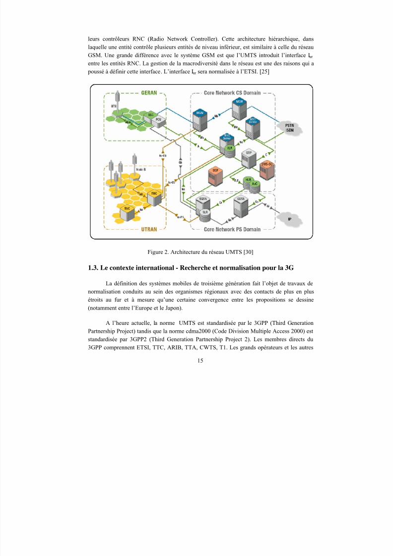
leurs contrôleurs RNC (Radio Network Controller). Cette architecture hiérarchique, dans
laquelle une entité contrôle plusieurs entités de niveau inférieur, est similaire à celle du réseau
GSM. Une grande différence avec le système GSM est que l’UMTS introduit l’interface Iur
entre les entités RNC. La gestion de la macrodiversité dans le réseau est une des raisons qui a
poussé à définir cette interface. L’interface Iur sera normalisée à l’ETSI. [25]
Figure 2. Architecture du réseau UMTS [30]
1.3. Le contexte international - Recherche et normalisation pour la 3G
La définition des systèmes mobiles de troisième génération fait l’objet de travaux de
normalisation conduits au sein des organismes régionaux avec des contacts de plus en plus
étroits au fur et à mesure qu’une certaine convergence entre les propositions se dessine(notamment entre l’Europe et le Japon).
A l’heure actuelle, la norme UMTS est standardisée par le 3GPP (Third Generation
Partnership Project) tandis que la norme cdma2000 (Code Division Multiple Access 2000) est
standardisée par 3GPP2 (Third Generation Partnership Project 2). Les membres directs du
3GPP comprennent ETSI, TTC, ARIB, TTA, CWTS, T1. Les grands opérateurs et les autres
15
8/12/2019 Stage-nguyen Huu Nghia
http://slidepdf.com/reader/full/stage-nguyen-huu-nghia 16/90
participent aux projets par l’intermédiaire des organismes régionaux.
Organismes régionaux Régions
ETSI (European Telecommunications Standards Institute) Europe
TTC (Telecommunication Technology Committee) et ARIB (Association of
Radio Industries and Businesses)
Japon
TTA (the Telecommunication Technology Association) Corée
CWTS (Chinese Wireless Telecommunications Standards) Chine
T1 Etats-Unis
Tableau 1 : Organismes régionaux participent au 3GPP
Chaque région a sa propre stratégie, fortement liée à la situation de développement des
systèmes de deuxième génération. En Europe, il faut souligner la place occupée dans la
normalisation par l’existence de groupes d’intérêt pour la troisième génération (MOU GSM,UMTS Forum) dont l’objectif est de fédérer, dans la mesure du possible, les positions des
opérateurs GSM et des industriels. [25]
2. Broadcast Multicast
2.1. Généralité
Au fur et à mesure de la convergence de l’internet et du multimédia, la méthode
unicast fondamentale, qui est la transmission de données en mode point à point , a évolué pour
faire face à de nouveaux besoins : la communication de un vers plusieurs ou plusieurs vers plusieurs.
Le broadcast est un terme anglais définissant une diffusion de données à un ensemble
de machines connectées à un réseau. En français on utilise le terme diffusion. Quant à
multicast, c’est une connexion réseau multipoint. Pourtant, il est au milieu de l’unicast et du
broadcast. Au lieu d’envoyer les données à une seule machine (unicast), ou à toutes les
machines dans le réseau (broadcast), il s’adresse à un groupe de certaines machines.
La notion de transmission multipoint peut être implémentée au niveau applicatif, par
exemple, lorsque l'on envoie un courrier électronique à une liste de destinataires ou que l'on poste une intervention dans un groupe de news. Mais cela devient rapidement lourd à gérer dès
que la liste de destinataires varie. D'autre part cela peut conduire à faire circuler de multiples
exemplaires des mêmes données sur un même lien, consommant ainsi de la bande passante.
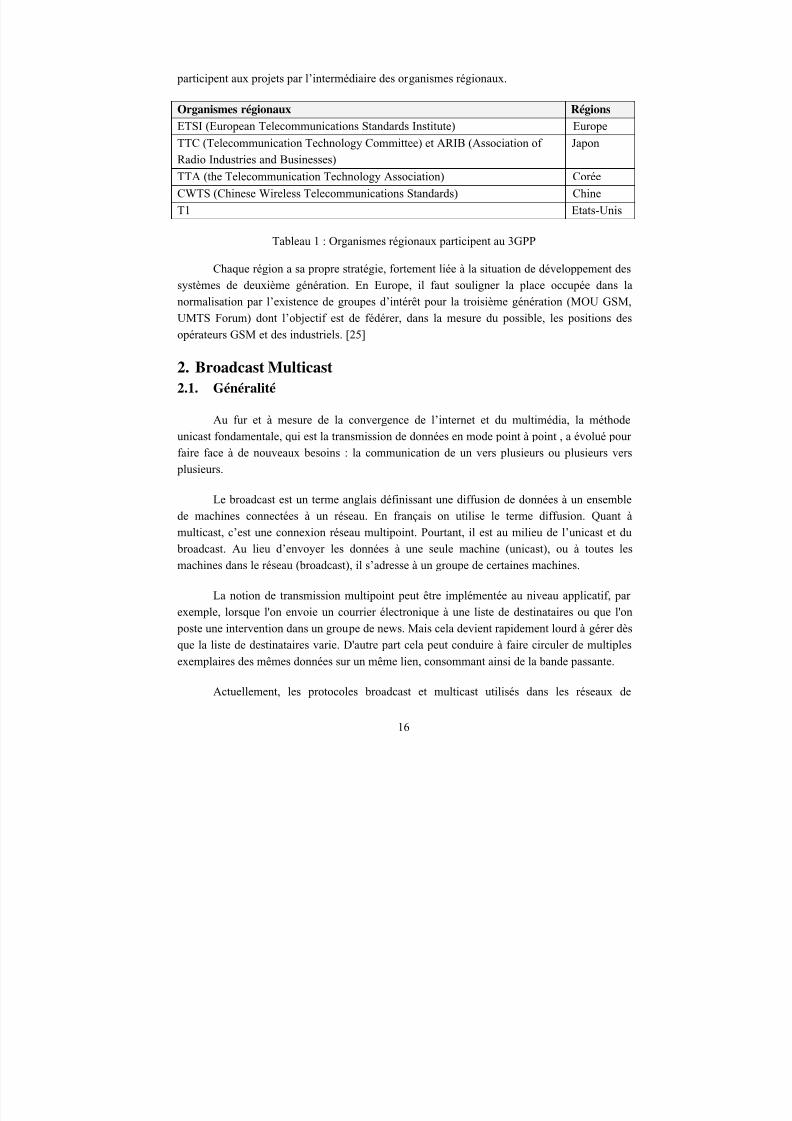
Actuellement, les protocoles broadcast et multicast utilisés dans les réseaux de
16
8/12/2019 Stage-nguyen Huu Nghia
http://slidepdf.com/reader/full/stage-nguyen-huu-nghia 17/90
diffusion des câblo-opérateurs, les réseaux informatiques et les réseaux de télécommunication
sont DVB-T/H, IETF Multicast et 3GPP MBMS. Le protocole MBMS du 3GPP sera présenté
avec plus de détails dans la partie qui suit.
DVB IETF IP Multicast 3GPP MBMS
Réseaux Réseaux hertziens de
diffusion des câblo-
opérateurs
(multimédia)
Réseaux sans fil
d’entreprise
(informatiques)
Réseaux de
télécommunication
(Mobile)
Organisation de
standadisation
ETSI IETF 3GPP
Documents DVB-T : EN
300 744, TR 101 190
DVB-H : EN 302 304
RFC 2710 TS 22.146, TS 22.346,
TS 25.331, TS 25.346,
TS 26.346, TS 29.846
Tableau 2: Protocols broadcast et multicast
2.2. Le protocole 3GPP MBMS
Pour les réseaux locaux sans fils d’entreprise, on utilise IP Multicast de l’IETF comme
solution. Dans [27], Mariann Hauge, Oyvind Kure ont présenté les approches pour exploiter le
protocole IP Multicast de l’IETF [34] dans les réseaux de télécommunications UMTS
(Universal Mobile Telecommunications System). Pourtant, les recherches ont également
montré que la seule utilisation de ce protocole dans un réseau UMTS n’assure pas une
optimisation d’utilisation des ressources radios. De même, le protocole IP Multicast se termine
dans le GGSN (Gateway GPRS Support Node) qui joue le rôle d’une passerelle entre Internet
et UMTS. Donc, bien qu’il puisse réduire la charge du serveur, il n’économise pas de bande
passante dans le réseau UMTS.
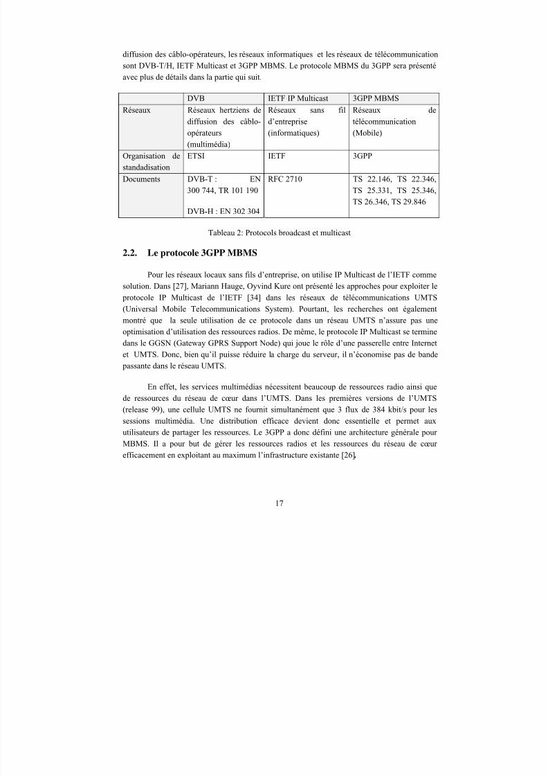
En effet, les services multimédias nécessitent beaucoup de ressources radio ainsi que
de ressources du réseau de cœur dans l’UMTS. Dans les premières versions de l’UMTS
(release 99), une cellule UMTS ne fournit simultanément que 3 flux de 384 kbit/s pour les
sessions multimédia. Une distribution efficace devient donc essentielle et permet auxutilisateurs de partager les ressources. Le 3GPP a donc défini une architecture générale pour
MBMS. Il a pour but de gérer les ressources radios et les ressources du réseau de cœur
efficacement en exploitant au maximum l’infrastructure existante [26].
17
8/12/2019 Stage-nguyen Huu Nghia
http://slidepdf.com/reader/full/stage-nguyen-huu-nghia 18/90
Figure 3. Architecture logique du MBMS [26]
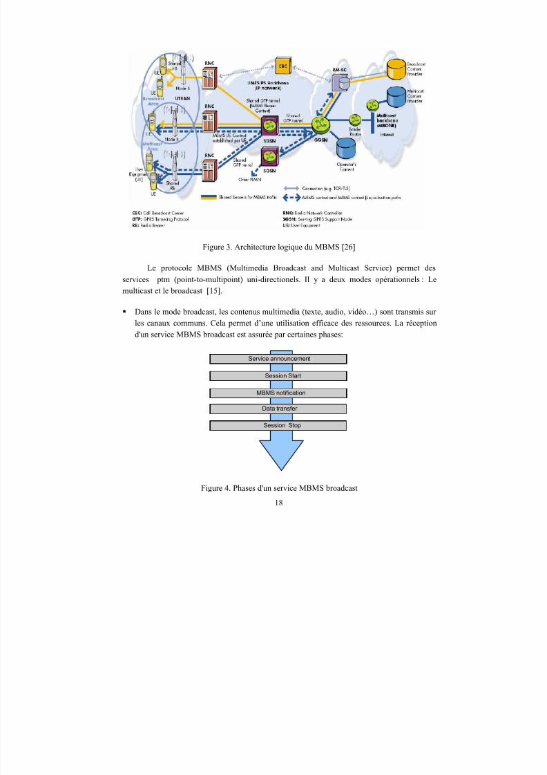
Le protocole MBMS (Multimedia Broadcast and Multicast Service) permet des
services ptm (point-to-multipoint) uni-directionels. Il y a deux modes opérationnels : Le
multicast et le broadcast [15].
Dans le mode broadcast, les contenus multimedia (texte, audio, vidéo…) sont transmis surles canaux communs. Cela permet d’une utilisation efficace des ressources. La réception
d'un service MBMS broadcast est assurée par certaines phases:
Service announcement
Data transfer
MBMS notification
Session Start
Session Stop
Figure 4. Phases d'un service MBMS broadcast
18
8/12/2019 Stage-nguyen Huu Nghia
http://slidepdf.com/reader/full/stage-nguyen-huu-nghia 19/90
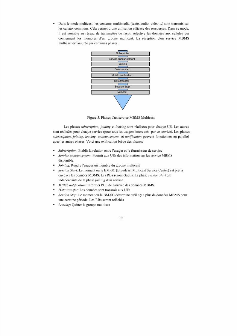
Dans le mode multicast, les contenus multimedia (texte, audio, vidéo…) sont transmis sur
les canaux communs. Cela permet d’une utilisation efficace des ressources. Dans ce mode,
il est possible au réseau de transmettre de façon sélective les données aux cellules qui
contiennent les membres d’un groupe multicast. La réception d'un service MBMS
multicast est assurée par certaines phases:
Subscription
Joining
Service announcement
Data transfer
Leaving
MBMS notification
Session start
Session Stop
Figure 5. Phases d'un service MBMS Multicast
Les phases subscription, joining et leaving sont réalisées pour chaque UE. Les autres
sont réalisées pour chaque service (pour tous les usagers intéressés par ce service). Les phases
subscription, joining, leaving, announcement et notification peuvent fonctionner en parallelavec les autres phases. Voici une explication brève des phases:
Subscription: Etablir la relation entre l'usager et le fournisseur de service
Service announcement : Fournir aux UEs des information sur les service MBMS
disponible.
Joining: Rendre l'usager un membre du groupe multicast
Session Start : Le moment où le BM-SC (Broadcast Multicast Service Center) est prêt à
envoyer les données MBMS. Les RBs seront établis. La phase session start est
indépendante de la phase joining d'un service MBMS notification: Informer l'UE de l'arrivée des données MBMS
Data transfer : Les données sont transmis aux UEs
Session Stop: Le moment où le BM-SC détermine qu'il n'y a plus de données MBMS pour
une certaine période. Les RBs seront relâchés
Leaving: Quitter le groupe multicast
19
8/12/2019 Stage-nguyen Huu Nghia
http://slidepdf.com/reader/full/stage-nguyen-huu-nghia 20/90
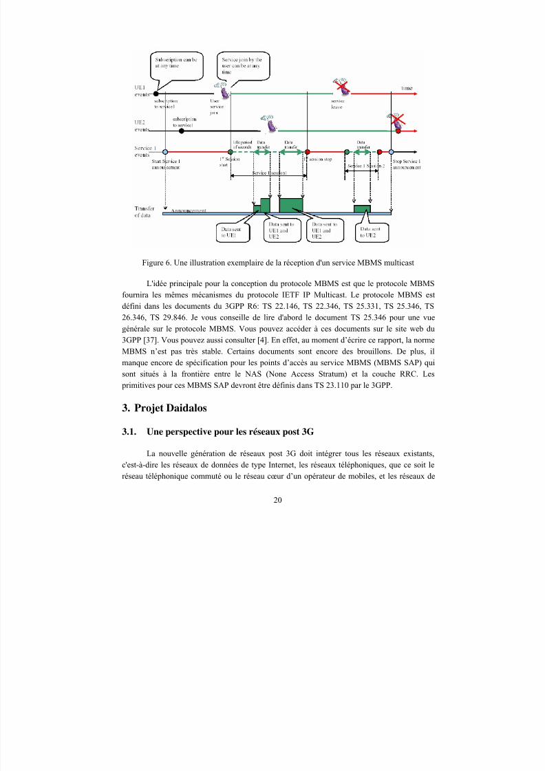
Figure 6. Une illustration exemplaire de la réception d'un service MBMS multicast
L'idée principale pour la conception du protocole MBMS est que le protocole MBMS
fournira les mêmes mécanismes du protocole IETF IP Multicast. Le protocole MBMS est
défini dans les documents du 3GPP R6: TS 22.146, TS 22.346, TS 25.331, TS 25.346, TS
26.346, TS 29.846. Je vous conseille de lire d'abord le document TS 25.346 pour une vue
générale sur le protocole MBMS. Vous pouvez accéder à ces documents sur le site web du
3GPP [37]. Vous pouvez aussi consulter [4]. En effet, au moment d’écrire ce rapport, la norme
MBMS n’est pas très stable. Certains documents sont encore des brouillons. De plus, il
manque encore de spécification pour les points d’accès au service MBMS (MBMS SAP) qui
sont situés à la frontière entre le NAS (None Access Stratum) et la couche RRC. Les
primitives pour ces MBMS SAP devront être définis dans TS 23.110 par le 3GPP.
3. Projet Daidalos
3.1. Une perspective pour les réseaux post 3G
La nouvelle génération de réseaux post 3G doit intégrer tous les réseaux existants,
c'est-à-dire les réseaux de données de type Internet, les réseaux téléphoniques, que ce soit le
réseau téléphonique commuté ou le réseau cœur d’un opérateur de mobiles, et les réseaux de
20
8/12/2019 Stage-nguyen Huu Nghia
http://slidepdf.com/reader/full/stage-nguyen-huu-nghia 21/90
vidéo pour effectuer de la diffusion de télévision ou de la vidéo à la demande. Pour avoir une
vision plus concrète, consultez [8, 10, 31, 32, 40]
La gestion de la mobilité et du nomadisme est aussi une propriété essentielle des
réseaux du XXIe siècle. Dans ces réseaux, les clients veulent se déplacer tout en restant
connectés. Le monde IP apporte des solutions à ce problème avec Mobile IP et Cellular IP, quigèrent la mobilité lente aussi bien que rapide. [8, 40]
3.2. Broadcast et Multicast dans le contexte du projet Daidalos
Dans le contexte du projet Daidalos, on étudie un réseau hétérogène qui assure bien le
“seamless mobility”. Les terminaux mobiles peuvent fonctionner dans n’importe quel réseau
sans fil, que ce soit les réseaux de diffusion, les réseaux de télécommunication ou les réseaux
informatiques d’entreprise.
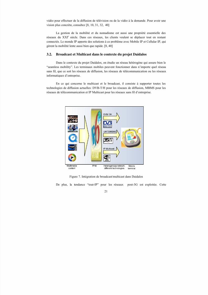
En ce qui concerne le multicast et le broadcast, il consiste à supporter toutes les
technologies de diffusion actuelles: DVB-T/H pour les réseaux de diffusion, MBMS pour les
réseaux de télécommunication et IP Multicast pour les réseaux sans fil d’entreprise.
Figure 7. Intégration de broadcast/multicast dans Daidalos
De plus, la tendance “tout-IP” pour les réseaux post-3G est exploitée. Cette
21
8/12/2019 Stage-nguyen Huu Nghia
http://slidepdf.com/reader/full/stage-nguyen-huu-nghia 22/90
architecture se place entièrement sur l’interface IPv6 ou, ce qui est équivalent, transporte
uniquement des paquets IP. Aux couches plus basses, on intègre des protocoles différents et
des technologies d’accès différentes. On peut donc introduire une vision comme suit: le
contenu multimédia est diffusé sur l’interface IPv6, et puis, traverse un réseau hétérogène qui
supporte des technologies différentes pour arriver aux terminaux mobiles post-3G.
4. Plate-forme TD-CDMA
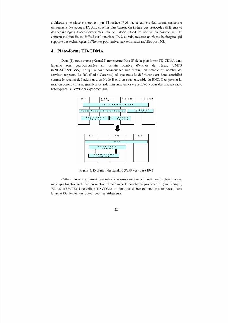
Dans [1], nous avons présenté l’architecture Pure-IP de la plateforme TD-CDMA dans
laquelle sont court-circuitées un certain nombre d’entités du réseau UMTS
(RNC/SGSN/GGSN), ce qui a pour conséquence une diminution notable du nombre de
services supports. Le RG (Radio Gateway) tel que nous le définissons est donc considéré
comme le résultat de l’addition d’un Node-B et d’un sous-ensemble du RNC. Ceci permet la
mise en oeuvre en vraie grandeur de solutions innovantes « pur-IPv6 » pour des réseaux radio
hétérogènes B3G/WLAN expérimentaux.
Figure 8. Evolution du standard 3GPP vers pure-IPv6
Cette architecture permet une interconnexion sans discontinuité des différents accès
radio qui fonctionnent tous en relation directe avec la couche de protocole IP (par exemple,
WLAN et UMTS). Une cellule TD-CDMA est donc considérée comme un sous réseau dans
laquelle RG devient un routeur pour les utilisateurs.
22
8/12/2019 Stage-nguyen Huu Nghia
http://slidepdf.com/reader/full/stage-nguyen-huu-nghia 23/90
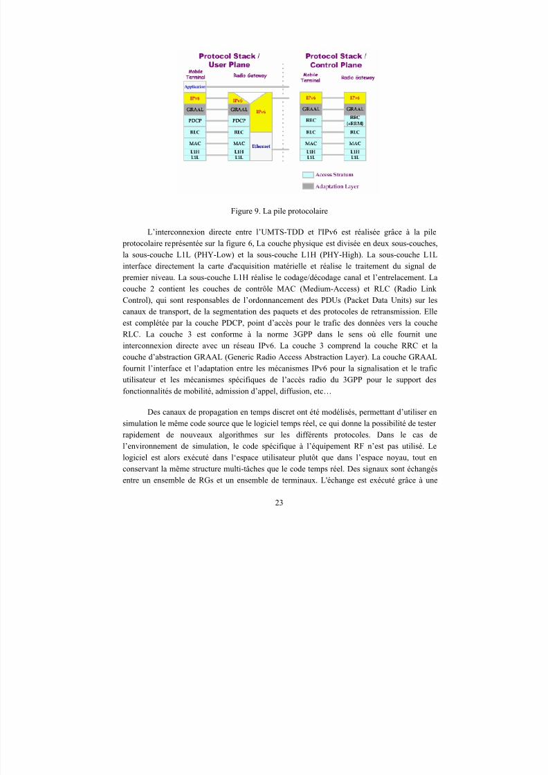
Figure 9. La pile protocolaire
L’interconnexion directe entre l’UMTS-TDD et l'IPv6 est réalisée grâce à la pile
protocolaire représentée sur la figure 6, La couche physique est divisée en deux sous-couches,
la sous-couche L1L (PHY-Low) et la sous-couche L1H (PHY-High). La sous-couche L1L
interface directement la carte d'acquisition matérielle et réalise le traitement du signal de
premier niveau. La sous-couche L1H réalise le codage/décodage canal et l’entrelacement. La
couche 2 contient les couches de contrôle MAC (Medium-Access) et RLC (Radio Link
Control), qui sont responsables de l’ordonnancement des PDUs (Packet Data Units) sur les
canaux de transport, de la segmentation des paquets et des protocoles de retransmission. Elleest complétée par la couche PDCP, point d’accès pour le trafic des données vers la couche
RLC. La couche 3 est conforme à la norme 3GPP dans le sens où elle fournit une
interconnexion directe avec un réseau IPv6. La couche 3 comprend la couche RRC et la
couche d’abstraction GRAAL (Generic Radio Access Abstraction Layer). La couche GRAAL
fournit l’interface et l’adaptation entre les mécanismes IPv6 pour la signalisation et le trafic
utilisateur et les mécanismes spécifiques de l’accès radio du 3GPP pour le support des
fonctionnalités de mobilité, admission d’appel, diffusion, etc…
Des canaux de propagation en temps discret ont été modélisés, permettant d’utiliser en
simulation le même code source que le logiciel temps réel, ce qui donne la possibilité de testerrapidement de nouveaux algorithmes sur les différents protocoles. Dans le cas de
l’environnement de simulation, le code spécifique à l’équipement RF n’est pas utilisé. Le
logiciel est alors exécuté dans l‘espace utilisateur plutôt que dans l’espace noyau, tout en
conservant la même structure multi-tâches que le code temps réel. Des signaux sont échangés
entre un ensemble de RGs et un ensemble de terminaux. L'échange est exécuté grâce à une
23
8/12/2019 Stage-nguyen Huu Nghia
http://slidepdf.com/reader/full/stage-nguyen-huu-nghia 24/90
interface socket client/serveur TCP/IP et à une troisième entité qui contrôle le flux du signal,
que nous appelons un Serveur de Canal (Channel Server). [2]
Une fonction qui n’est pas présentée dans les stations de base mais dans le RNC est le
RRM (Radio Ressource Management) dont les algorithmes doivent gérer les ressources radio
de plusieurs cellules adjacentes. Le RRM est mis en oeuvre de façon centralisée pour ungroupe de RGs. L’entité RRM fournit les fonctions suivantes aux clients RGs qu’elle gère:
1. configuration automatique de l’Access Stratum à partir des requêtes de service basées sur la QdS.2. réduction des parasites (contrôle de puissance, allocation dynamique de canal)3. gestion de la mobilité de bas niveau (par exemple, contrôle du « Soft Handover »)4. gestion de ressources conjointe à travers plusieurs technologies d’accès différentes(UMTS/WLAN)5. recueil et algorithmique du traitement des mesures.
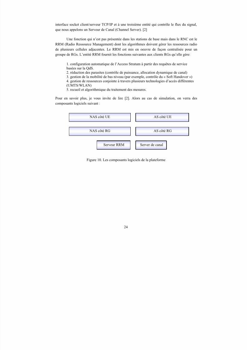
Pour en savoir plus, je vous invite de lire [2]. Alors au cas de simulation, on verra des
composants logiciels suivant :
NAS côté UE AS côté UE
NAS côté RG AS côté RG
Serveur RRM Server de canal
Figure 10. Les composants logiciels de la plateforme
24
8/12/2019 Stage-nguyen Huu Nghia
http://slidepdf.com/reader/full/stage-nguyen-huu-nghia 25/90
Chapitre
3CHAPITRE 3 – VERS UNE PLATEFORME TD-CDMA
MULTICAST
Ce chapitre est consacré à la solution pour la problématique mentionnée. Un processus
strict de recherche et développement sera présenté. En plus, les adaptations de la norme en
tenant compte des exigences et des hypothèses seront précisées aussi.
1. Description
Le processus se divise en trois phases qui sont étroitement liés au processus denormalisation du 3GPP. Comme la norme MBMS n’est pas stable en ce moment, il faut faire
attention que, en réalisant ces trois phases, on suive toujours les compte-rendus des réunions
du 3GPP – RAN WG2.
25
8/12/2019 Stage-nguyen Huu Nghia
http://slidepdf.com/reader/full/stage-nguyen-huu-nghia 26/90
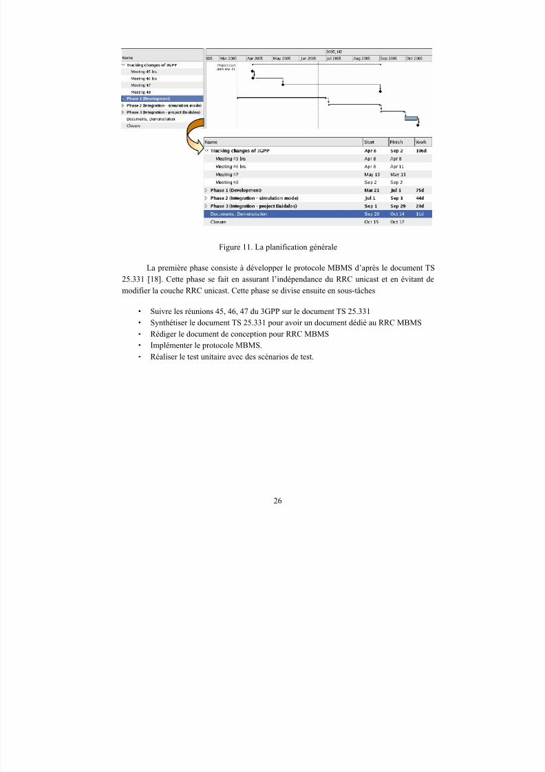
Figure 11. La planification générale
La première phase consiste à développer le protocole MBMS d’après le document TS
25.331 [18]. Cette phase se fait en assurant l’indépendance du RRC unicast et en évitant de
modifier la couche RRC unicast. Cette phase se divise ensuite en sous-tâches
Suivre les réunions 45, 46, 47 du 3GPP sur le document TS 25.331 Synthétiser le document TS 25.331 pour avoir un document dédié au RRC MBMS
Rédiger le document de conception pour RRC MBMS
Implémenter le protocole MBMS.
Réaliser le test unitaire avec des scénarios de test.
26
8/12/2019 Stage-nguyen Huu Nghia
http://slidepdf.com/reader/full/stage-nguyen-huu-nghia 27/90
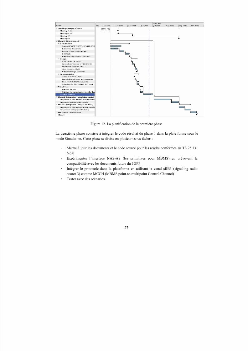
Figure 12. La planification de la première phase
La deuxième phase consiste à intégrer le code résultat du phase 1 dans la plate forme sous le
mode Simulation. Cette phase se divise en plusieurs sous-tâches :
Mettre à jour les documents et le code source pour les rendre conformes au TS 25.331
6.6.0
Expérimenter l’interface NAS-AS (les primitives pour MBMS) en prévoyant la
compatibilité avec les documents futurs du 3GPP
Intégrer le protocole dans la plateforme en utilisant le canal sRB3 (signaling radio
bearer 3) comme MCCH (MBMS point-to-multipoint Control Channel)
Tester avec des scénarios.
27
8/12/2019 Stage-nguyen Huu Nghia
http://slidepdf.com/reader/full/stage-nguyen-huu-nghia 28/90
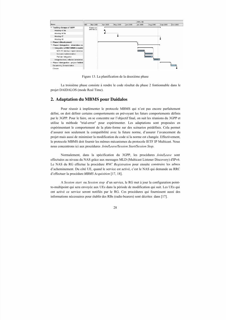
Figure 13. La planification de la deuxième phase
La troisième phase consiste à rendre le code résultat du phase 2 fontionnable dans le projet DAIDALOS (mode Real Time).
2. Adaptation du MBMS pour Daidalos
Pour réussir à implémenter le protocole MBMS qui n’est pas encore parfaitement
défini, on doit définir certains comportements en prévoyant les futurs comportements définis
par le 3GPP. Pour le faire, on se concentre sur l’objectif final, on suit les réunions du 3GPP et
utilise la méthode "trial-error" pour expérimenter. Les adaptations sont proposées en
expérimentant le comportement de la plate-forme sur des scénarios prédéfinis. Cela permet
d’assurer non seulement la compatibilité avec la future norme, d’assurer l’avancement du
projet mais aussi de minimiser la modification du code si la norme est changée. Effectivement,
le protocole MBMS doit fournir les mêmes mécanismes du protocole IETF IP Multicast. Nous
nous concentrons ici aux procédures Join/Leave/Session Start/Session Stop.
Normalement, dans la spécification du 3GPP, les procédures Join/Leave sont
effectuées au niveau du NAS grâce aux messages MLD (Multicast Listener Discovery) d'IPv6.
Le NAS du RG effectue la procédure RNC Registration pour ensuite construire les arbres
d’acheminement. Du côté UE, quand le service est activé, c’est le NAS qui demande au RRC
d’effectuer la procédure MBMS Acquisition [17, 18].
A Session start ou Session stop d’un service, le RG met à jour la configuration point-
to-multipoint qui sera envoyée aux UEs dans la période de modification qui suit. Les UEs qui
ont activé ce service seront notifiés par le RG. Ces procédures qui fournissent aussi des
informations nécessaires pour établir des RBs (radio bearers) sont décrites dans [17].
28
8/12/2019 Stage-nguyen Huu Nghia
http://slidepdf.com/reader/full/stage-nguyen-huu-nghia 29/90
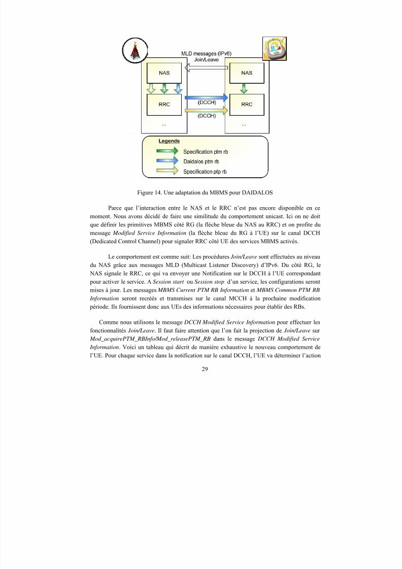
Figure 14. Une adaptation du MBMS pour DAIDALOS
Parce que l’interaction entre le NAS et le RRC n’est pas encore disponible en ce
moment. Nous avons décidé de faire une similitude du comportement unicast. Ici on ne doit
que définir les primitives MBMS côté RG (la flèche bleue du NAS au RRC) et on profite du
message Modified Service Information (la flèche bleue du RG à l’UE) sur le canal DCCH(Dedicated Control Channel) pour signaler RRC côté UE des services MBMS activés.
Le comportement est comme suit: Les procédures Join/Leave sont effectuées au niveau
du NAS grâce aux messages MLD (Multicast Listener Discovery) d’IPv6. Du côté RG, le
NAS signale le RRC, ce qui va envoyer une Notification sur le DCCH à l’UE correspondant
pour activer le service. A Session start ou Session stop d’un service, les configurations seront
mises à jour. Les messages MBMS Current PTM RB Information et MBMS Common PTM RB
Information seront recréés et transmises sur le canal MCCH à la prochaine modification
période. Ils fournissent donc aux UEs des informations nécessaires pour établir des RBs.
Comme nous utilisons le message DCCH Modified Service Information pour effectuer les
fonctionnalités Join/Leave. Il faut faire attention que l’on fait la projection de Join/Leave sur Mod_acquirePTM_RBInfo/Mod_releasePTM_RB dans le message DCCH Modified Service
Information. Voici un tableau qui décrit de manière exhaustive le nouveau comportement de
l’UE. Pour chaque service dans la notification sur le canal DCCH, l’UE va déterminer l’action
29
8/12/2019 Stage-nguyen Huu Nghia
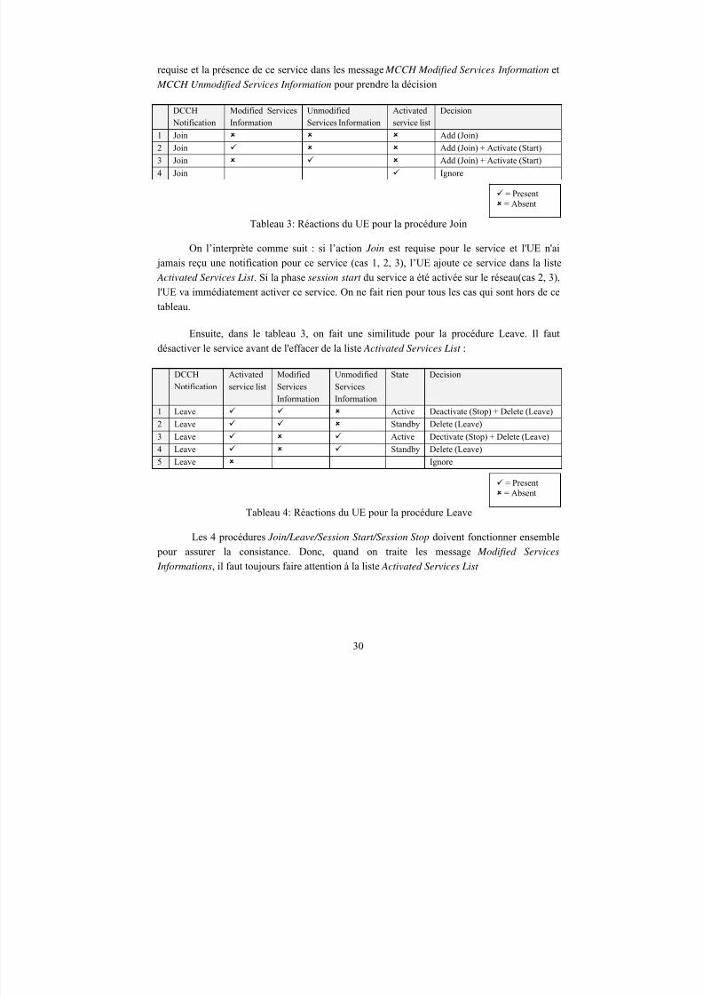
http://slidepdf.com/reader/full/stage-nguyen-huu-nghia 30/90
requise et la présence de ce service dans les message MCCH Modified Services Information et
MCCH Unmodified Services Information pour prendre la décision
DCCH Notification
Modified ServicesInformation
UnmodifiedServices Information
Activatedservice list
Decision
1 Join Add (Join)2 Join Add (Join) + Activate (Start)
3 Join Add (Join) + Activate (Start)
4 Join Ignore
= Present = Absent
Tableau 3: Réactions du UE pour la procédure Join
On l’interprète comme suit : si l’action Join est requise pour le service et l'UE n'ai
jamais reçu une notification pour ce service (cas 1, 2, 3), l’UE ajoute ce service dans la liste Activated Services List . Si la phase session start du service a été activée sur le réseau(cas 2, 3),
l'UE va immédiatement activer ce service. On ne fait rien pour tous les cas qui sont hors de ce
tableau.
Ensuite, dans le tableau 3, on fait une similitude pour la procédure Leave. Il faut
désactiver le service avant de l'effacer de la liste Activated Services List :
DCCH
Notification
Activated
service list
Modified
Services
Information
Unmodified
Services
Information
State Decision
1 Leave Active Deactivate (Stop) + Delete (Leave)
2 Leave Standby Delete (Leave)
3 Leave Active Dectivate (Stop) + Delete (Leave)
4 Leave Standby Delete (Leave)
5 Leave Ignore
= Present = Absent
Tableau 4: Réactions du UE pour la procédure Leave
Les 4 procédures Join/Leave/Session Start/Session Stop doivent fonctionner ensemble pour assurer la consistance. Donc, quand on traite les message Modified Services
Informations, il faut toujours faire attention à la liste Activated Services List
30
8/12/2019 Stage-nguyen Huu Nghia
http://slidepdf.com/reader/full/stage-nguyen-huu-nghia 31/90
Required Action (of Modified
Services Information)
Activated service
list
State Decision
1 Mod_acquirePTM_RBInfo Standby Activate the service whenever the
configuration point-to-multipoint is
available
2 Mod_releasePTM_RB
Active Deactivate the service3 Ignore
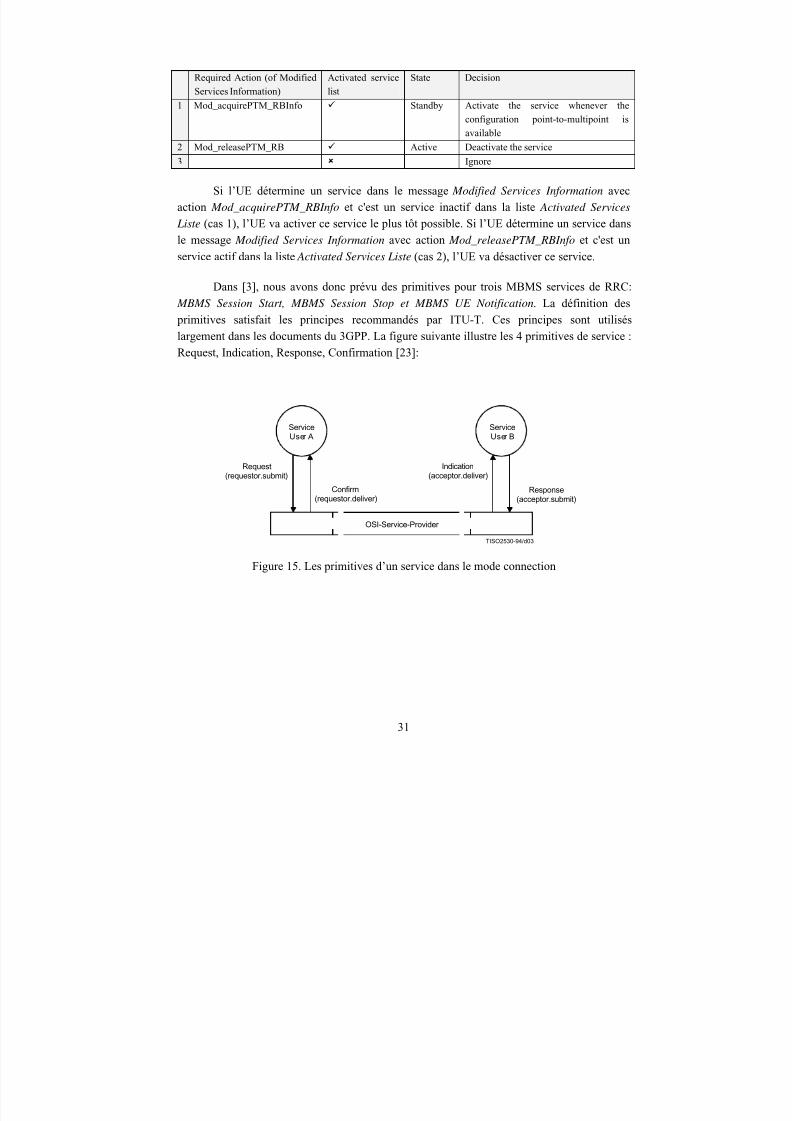
Si l’UE détermine un service dans le message Modified Services Information avecaction Mod_acquirePTM_RBInfo et c'est un service inactif dans la liste Activated Services
Liste (cas 1), l’UE va activer ce service le plus tôt possible. Si l’UE détermine un service dans
le message Modified Services Information avec action Mod_releasePTM_RBInfo et c'est un
service actif dans la liste Activated Services Liste (cas 2), l’UE va désactiver ce service.
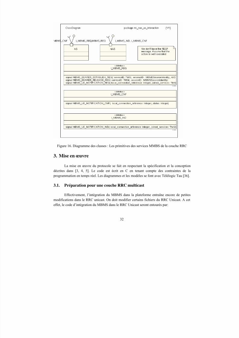
Dans [3], nous avons donc prévu des primitives pour trois MBMS services de RRC:
MBMS Session Start, MBMS Session Stop et MBMS UE Notification. La définition des primitives satisfait les principes recommandés par ITU-T. Ces principes sont utilisés
largement dans les documents du 3GPP. La figure suivante illustre les 4 primitives de service :
Request, Indication, Response, Confirmation [23]:
TISO2530-94/d03
ServiceUser A
ServiceUser B
OSI-Service-Provider
Request(requestor.submit)
Confirm(requestor.deliver)
Indication(acceptor.deliver)
Response(acceptor.submit)
Figure 15. Les primitives d’un service dans le mode connection
31
8/12/2019 Stage-nguyen Huu Nghia
http://slidepdf.com/reader/full/stage-nguyen-huu-nghia 32/90
8/12/2019 Stage-nguyen Huu Nghia
http://slidepdf.com/reader/full/stage-nguyen-huu-nghia 33/90
#ifdef ALLOW_MBMS_ PROTOCOL<Code pour MBMS>#endif
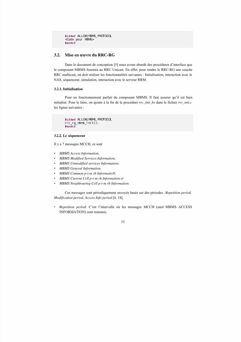
3.2. Mise en œuvre du RRC-RG
Dans le document de conception [5] nous avons abordé des procédures d’interface que
le composant MBMS fournira au RRC Unicast. En effet, pour rendre le RRC-RG une couche
RRC multicast, on doit réaliser les fonctionnalités suivantes : Initialisation, interaction avec le
NAS, séquenceur, simulation, interaction avec le serveur RRM.
3.2.1. Initialisation
Pour un fonctionnement parfait du composant MBMS. Il faut assurer qu’il est bien
initialisé. Pour le faire, on ajoute à la fin de la procédure rrc_init_bs dans le fichier rrc_init.c
les lignes suivantes :
#ifdef ALLOW_MBMS_ PROTOCOLr r c_r g_mbms_i ni t ( ) ;#endif
3.2.2. Le séquenceur
Il y a 7 messages MCCH, ce sont
MBMS Access Information,
MBMS Modified Services Information,
MBMS Unmodified services Information,
MBMS General Information,
MBMS Common p-t-m rb InformatioN,
MBMS Current Cell p-t-m rb Information et
MBMS Neighbouring Cell p-t-m rb Information.
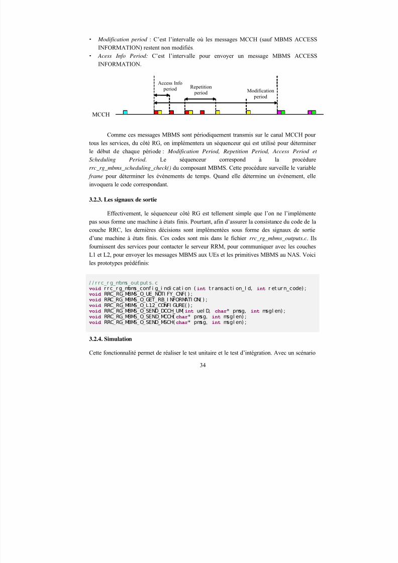
Ces messages sont périodiquement envoyés basés sur des périodes : Repetition period,
Modification period , Access Info period [4, 18].
Repetition period : C’est l’intervalle où les messages MCCH (sauf MBMS ACCESS
INFORMATION) sont transmis.
33
8/12/2019 Stage-nguyen Huu Nghia
http://slidepdf.com/reader/full/stage-nguyen-huu-nghia 34/90
8/12/2019 Stage-nguyen Huu Nghia
http://slidepdf.com/reader/full/stage-nguyen-huu-nghia 35/90
prédéfini on peut vérifier le fonctionnement interne de la couche RRC. Pour la réaliser, on a
deux façons :
Au niveau du NAS : le NAS peut gérer les primitives définies dans [3] et les envoie auRRC. Le RRC va ensuite traiter ces primitives. Dans ce cas, il suffit d’ajouter l’appelnas_mbms_scenario_check() dans la procédure nas_rg_DC_Rcve_FIFO() du fichier NAS/SIM/nas_rg_control_user.c.
Au niveau du RRC : le RRC peut directement simuler comme s’il a reçu des primitives du NAS. Dans la procédure rrc_rg_rxtx() du fichier rrc_nas_if.c, on ajoute l’appelrrc_rg_mbms_scenario_check() just après l’appel rrc_rg_mbms_scheduling_check()
3.2.5. Interaction avec le NAS
Le RRC du RG se charge aussi de traiter les primitives MBMS qui viennent du NAS.
Cette fonctionnalité fournit un SAP (Service Access Point) à la couche NAS. Il se charge detraiter les primitives MBMS_<PRIMITIVE_NAME>_REQ qui viennent du NAS. Lesinformations ne sont pas disponibles aux UEs tout de suite [4, 18]. Effectivement, cesinformations seront validées à la modification period qui suit. On voit par exemple dans les
scénarios suivants :
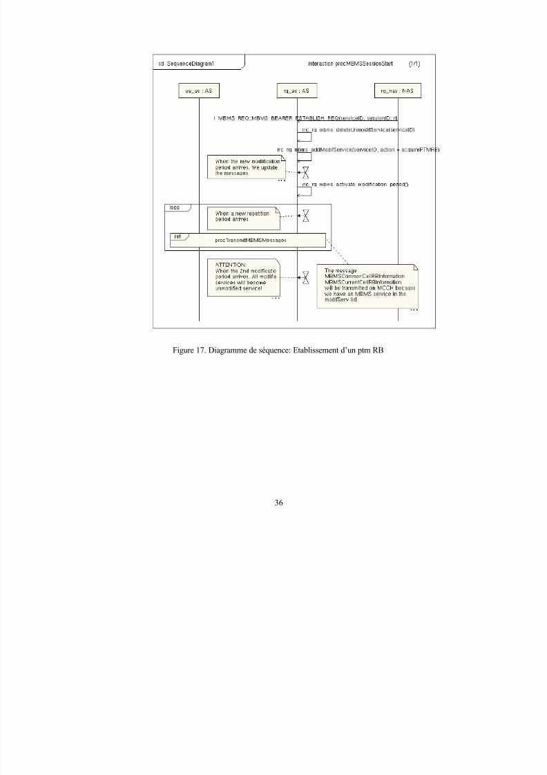
A session start ou session stop, le RRC du RG reçoit une primitiveMBMS_BEARER_ESTABLIS_REQ, il va mettre à jour les message MBMS MODIFIEDSERVICE INFORMATION et MBMS UNMODIFIED SERVICE INFORATION. Pourtant,ces nouveaux changements ne sont transmis aux UEs qu’à la prochaine modification period [4,
18].
35
8/12/2019 Stage-nguyen Huu Nghia
http://slidepdf.com/reader/full/stage-nguyen-huu-nghia 36/90
Figure 17. Diagramme de séquence: Etablissement d’un ptm RB
36
8/12/2019 Stage-nguyen Huu Nghia
http://slidepdf.com/reader/full/stage-nguyen-huu-nghia 37/90
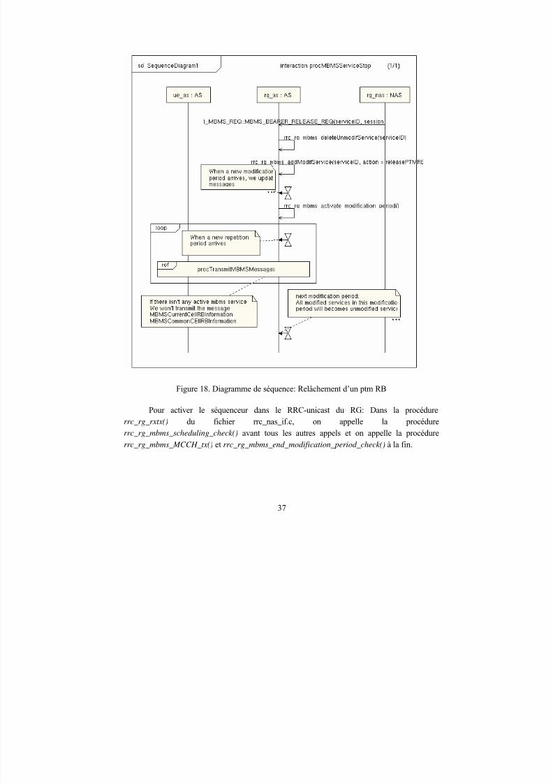
Figure 18. Diagramme de séquence: Relâchement d’un ptm RB
Pour activer le séquenceur dans le RRC-unicast du RG: Dans la procédure
rrc_rg_rxtx() du fichier rrc_nas_if.c, on appelle la procédurerrc_rg_mbms_scheduling_check() avant tous les autres appels et on appelle la procédurerrc_rg_mbms_MCCH_tx() et rrc_rg_mbms_end_modification_period_check() à la fin.
37
8/12/2019 Stage-nguyen Huu Nghia
http://slidepdf.com/reader/full/stage-nguyen-huu-nghia 38/90
Dans la procédure rrc_rg_read_DCin_FIFO() du fichier rrc_rg_msg_decode.c, on ajoutele code qui traite la primitive MBMS_UE_NOTIFY_REQ
Dans la procédure rrc_rg_read_GC_FIFO du fichier rrc_rg_msg_decode.c on ajoute lecode qui traite les primitives MBMS_BEARER_ESTABLISH_REQ etMBMS_BEARER_RELEASE_REQ
3.2.6. Interaction avec le serveur RRM
En effet, quand on envoie une demande au serveur RRM, on doit attendre la réponse. Ilest donc nécessaire au composant MBMS de savoir le moment où la configuration point-to-multipoint est disponible. Pour le faire, on modifie un peu la procédurerrc_process_commands(int tx_idP) dans CONTRIB/rrc_message_handler.c comme suit :
Avant rr c_conf i g_i ndi cat i on( t x_i dP, 0) ;
Aprèsif ( t x_i dP < MBMS_MI N_TRANSACTI ON_I D)
rr c_conf i g_i ndi cat i on( t x_i dP, 0) ;else if ( t x_ i dP >= MBMS_MI N_TRANSACTI ON_I D && t x_ i dP <=MBMS_MAX_TRANSACTI ON_I D)
r r c_r g_mbms_conf i g_i ndi cat i on ( t x_i dP, 0) ;
Ici je considère que toutes les transactions RRM avec id supérieur ou égal àMBMS_MIN_TRANSACTION_ID et inférieur ou égale à MBMS_MAX_TRANSACTIONsont des transactions RRM pour MBMS.
3.3. Mise en œuvre du RRC-UE
Quant au RRC côté UE, il faut tout d’abord assurer l’initialisation du composantMBMS. En plus, on doit assurer la capacité de recevoir et décoder les messages sur le canalMCCH et la notification sur le canal DCCH. Actuellement, le canal MCCH n’est pasdisponible dans la plateforme. Pour assurer l’avancement, on doit temporairement utiliser lesRB3 qui est dédié aux messages DCCH Downlink Direct Transfer portant la signalisation NAS [18 section 6.3]. Dans le RRC côté UE, on implémentera une machine à états finis pour prendre la décision.
3.3.1. Initialisation
Pour un fonctionnement parfait du composant MBMS, il faut assurer qu’il est bieninitialisé. Pour le faire, on ajoute à la fin de la procédure rrc_init_ms() dans le fichierrrc_init.c les lignes suivantes:
#ifdef ALLOW_MBMS_ PROTOCOLr r c_ue_mbms_i ni t ( ) ;
38
8/12/2019 Stage-nguyen Huu Nghia
http://slidepdf.com/reader/full/stage-nguyen-huu-nghia 39/90
#endif
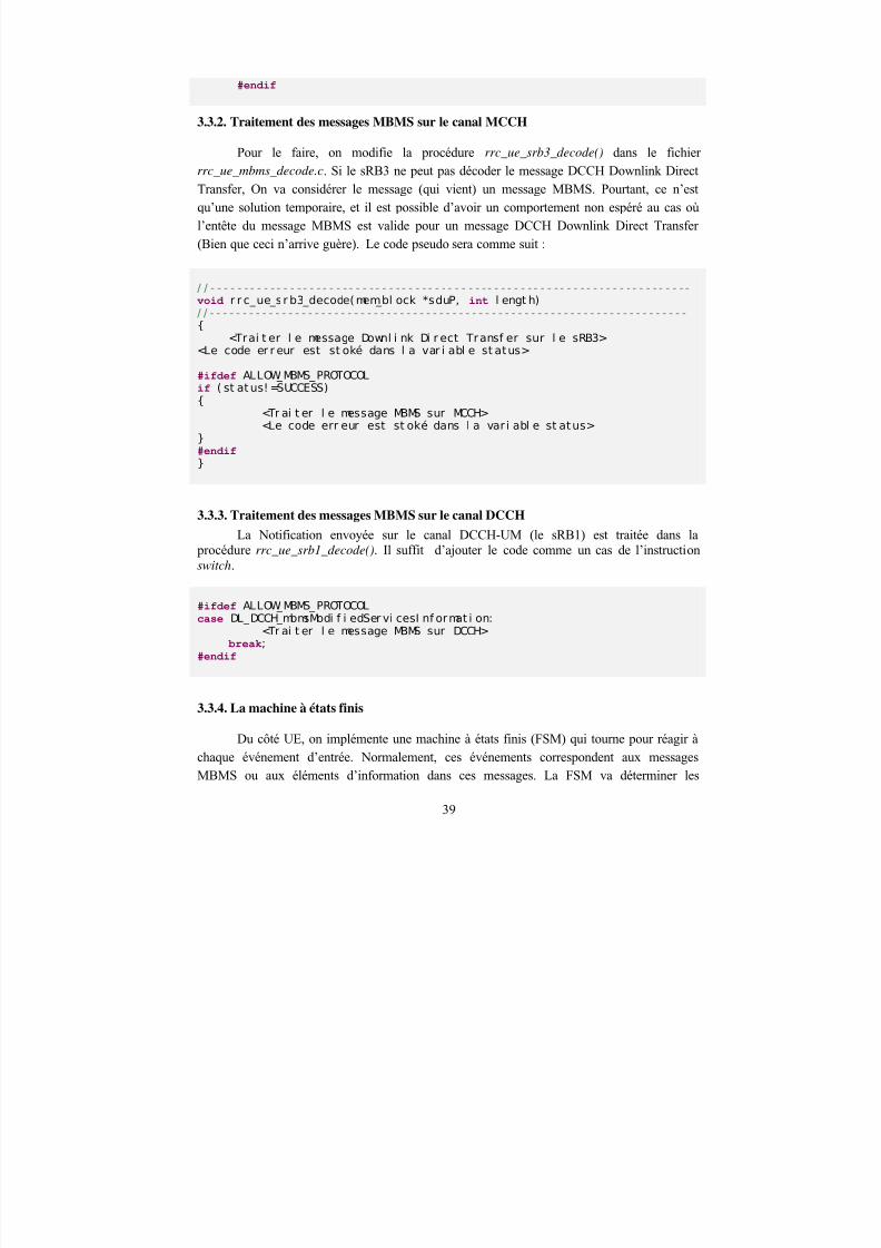
3.3.2. Traitement des messages MBMS sur le canal MCCH
Pour le faire, on modifie la procédure rrc_ue_srb3_decode() dans le fichier
rrc_ue_mbms_decode.c. Si le sRB3 ne peut pas décoder le message DCCH Downlink DirectTransfer, On va considérer le message (qui vient) un message MBMS. Pourtant, ce n’estqu’une solution temporaire, et il est possible d’avoir un comportement non espéré au cas oùl’entête du message MBMS est valide pour un message DCCH Downlink Direct Transfer(Bien que ceci n’arrive guère). Le code pseudo sera comme suit :
/ / - - - - -- - - - - - - - - - - - - - - - - - - - - - - - - - - - - - - - - - - - - - - - - - - - - - - - - - - - - - - - - - - - - - - - - - - - void r r c_ue_sr b3_decode(mem_bl ock *sduP, int l engt h)/ / - - - - - - - - - - - - - - - - - - - - - - - - - - - - - - - - - - - - - - - - - - - - - - - - - - - - - - - - - - - - - - - - - - - - - - - - - {
<Trai t er l e message Downl i nk Di r ect Transf er sur l e sRB3><Le code er r eur est st oké dans l a var i abl e st atus>
#ifdef ALLOW_MBMS_PROTOCOLif ( st at us! =SUCCESS){
<Tr ai t er l e message MBMS sur MCCH><Le code err eur est st oké dans l a var i abl e st atus>
}#endif }
3.3.3. Traitement des messages MBMS sur le canal DCCH
La Notification envoyée sur le canal DCCH-UM (le sRB1) est traitée dans la procédure rrc_ue_srb1_decode(). Il suffit d’ajouter le code comme un cas de l’instructionswitch.
#ifdef ALLOW_MBMS_PROTOCOLcase DL_DCCH_mbmsModi f i edSer vi cesI nf ormat i on:
<Tr ai t er l e message MBMS sur DCCH> break;
#endif
3.3.4. La machine à états finis
Du côté UE, on implémente une machine à états finis (FSM) qui tourne pour réagir àchaque événement d’entrée. Normalement, ces événements correspondent aux messagesMBMS ou aux éléments d’information dans ces messages. La FSM va déterminer les
39
8/12/2019 Stage-nguyen Huu Nghia
http://slidepdf.com/reader/full/stage-nguyen-huu-nghia 40/90
événements de sortie et activer le code correspondant. Il faut faire attention que
l’implémentation de cette machine est influencée par les adaptations.
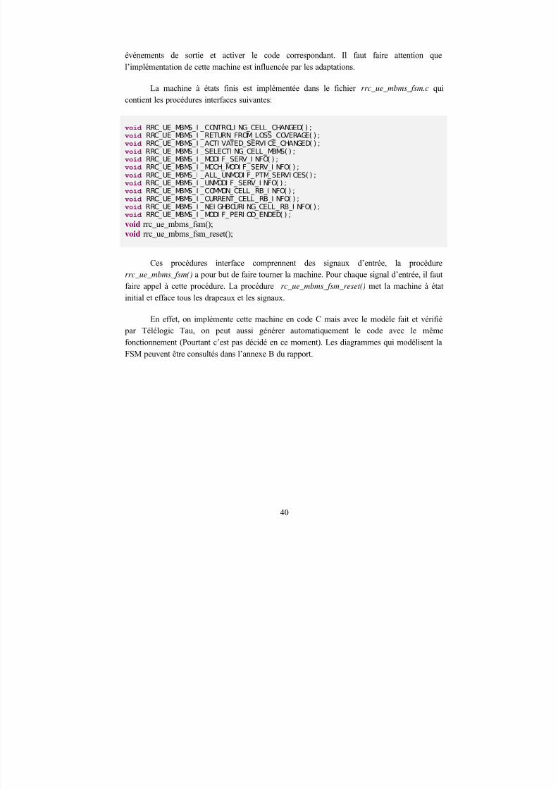
La machine à états finis est implémentée dans le fichier rrc_ue_mbms_fsm.c quicontient les procédures interfaces suivantes:
void RRC_UE_MBMS_I _CONTROLI NG_CELL_CHANGED( ) ;void RRC_UE_MBMS_I _RETURN_FROM_LOSS_COVERAGE( ) ;void RRC_UE_MBMS_I _ACTI VATED_SERVI CE_CHANGED( ) ;void RRC_UE_MBMS_I _SELECTI NG_CELL_MBMS( ) ;void RRC_UE_MBMS_I _MODI F_SERV_I NFO( ) ;void RRC_UE_MBMS_I _MCCH_MODI F_SERV_I NFO( ) ;void RRC_UE_MBMS_I _ALL_UNMODI F_PTM_SERVI CES( ) ;void RRC_UE_MBMS_I _UNMODI F_SERV_I NFO( ) ;void RRC_UE_MBMS_I _COMMON_CELL_RB_I NFO( ) ;void RRC_UE_MBMS_I _CURRENT_CELL_RB_I NFO( ) ;void RRC_UE_MBMS_I _NEI GHBOURI NG_CELL_RB_I NFO( ) ;
void RRC_UE_MBMS_I _MODI F_PERI OD_ENDED( ) ;void rrc_ue_mbms_fsm();void rrc_ue_mbms_fsm_reset();
Ces procédures interface comprennent des signaux d’entrée, la procédurerrc_ue_mbms_fsm() a pour but de faire tourner la machine. Pour chaque signal d’entrée, il fautfaire appel à cette procédure. La procédure rc_ue_mbms_fsm_reset() met la machine à état
initial et efface tous les drapeaux et les signaux.
En effet, on implémente cette machine en code C mais avec le modèle fait et vérifié par Télélogic Tau, on peut aussi générer automatiquement le code avec le mêmefonctionnement (Pourtant c’est pas décidé en ce moment). Les diagrammes qui modélisent la
FSM peuvent être consultés dans l’annexe B du rapport.
40

8/12/2019 Stage-nguyen Huu Nghia
http://slidepdf.com/reader/full/stage-nguyen-huu-nghia 41/90
CHAPITRE 4 – EVALUATION
Ce chapitre vous montrera les résultats de mon stage pendant 7 mois. En fait, dans le mondeindustriel, le protocole MBMS ne sera mis en place que dans au moins un ou deux ans. Ceseront les premières expérimentations. Il faut donc:
Valider les adaptations
Vérifier que l’implémentation est conforme au 3GPP R6
1. Critères d’évaluation
Dans le cadre du stage, l’évaluation ne s’adresse pas à la performance du protocole MBMSmais plutôt à la validité du protocole. Je me permets de mettre ici certains critères utilisés:Indépendance, Tolérance au fautes, Conformité au 3GPP, Stabilité:
Le composant MBMS doit fonctionner de façon indépendante: Il fonctionne comme une boite noire, comme un système réactif avec des signaux d’entrée et des signaux de sortie.On peut le tester avant de l’intégrer dans la plateforme.
Le composant MBMS doit assurer la tolérance aux fautes: Il doit être capable de réagir auxsignaux inattendus sans se casser. Il est aussi important d’éviter les fautes de programmation (segmentation fault, broken pipe…)
Le composant MBMS doit assurer la conformité au 3GPP: Le code, les conventions, lefonctionnement doivent bien respecter la norme du 3GPP.
Le composant MBMS doit assurer la stabilité: Il doit fonctionner long temps sans ralentirle système, sans gaspiller les ressources du système (Mémoire, CPU…).
Le RRC Multicast doit fournir le service MBMS en assurant toutes les fonctionnalités du
RRC Unicast.
2. Banc de test
Le test est effectué avec
Système Linux Redhat 7 - kernel 2.4.20
Chapitre
4
41
8/12/2019 Stage-nguyen Huu Nghia
http://slidepdf.com/reader/full/stage-nguyen-huu-nghia 42/90
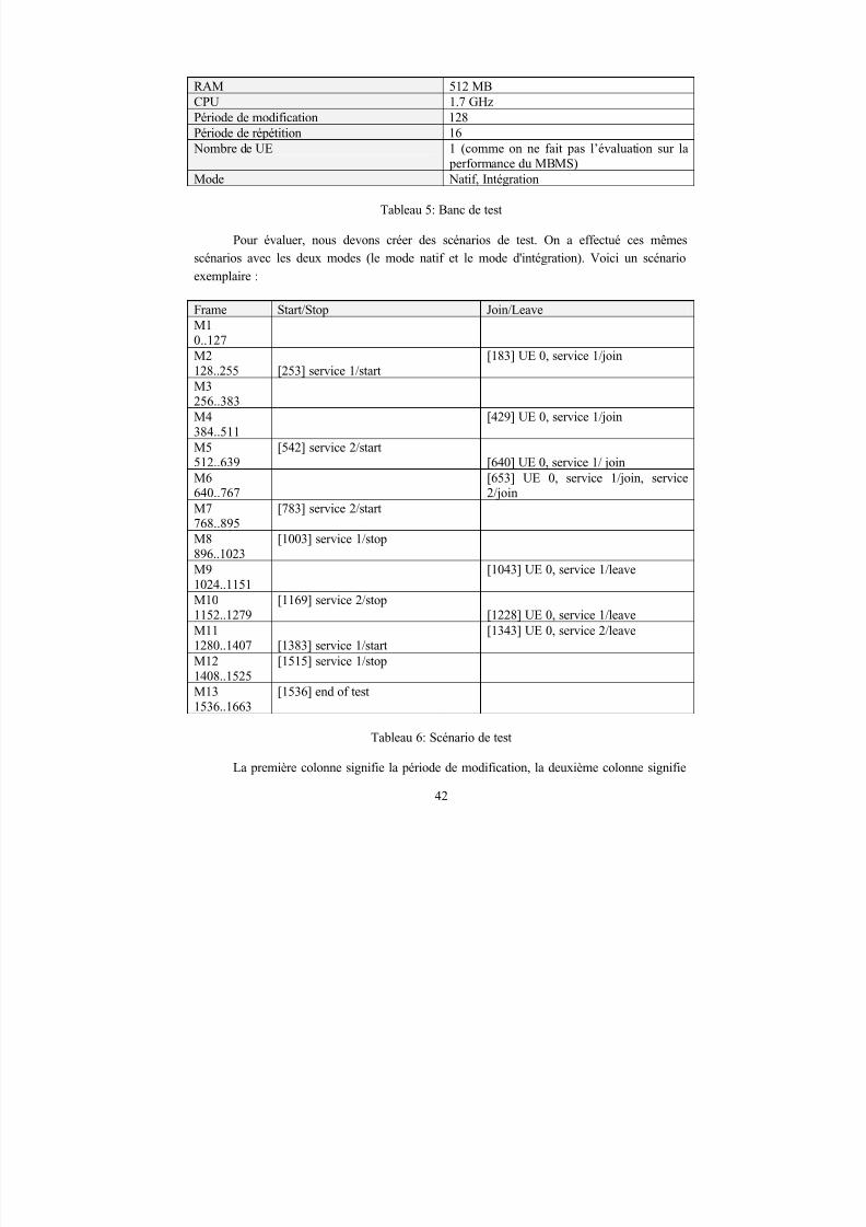
RAM 512 MBCPU 1.7 GHzPériode de modification 128Période de répétition 16 Nombre de UE 1 (comme on ne fait pas l’évaluation sur la
performance du MBMS)Mode Natif, Intégration
Tableau 5: Banc de test
Pour évaluer, nous devons créer des scénarios de test. On a effectué ces mêmesscénarios avec les deux modes (le mode natif et le mode d'intégration). Voici un scénario
exemplaire :
Frame Start/Stop Join/Leave
M10..127M2128..255 [253] service 1/start
[183] UE 0, service 1/join
M3256..383M4384..511
[429] UE 0, service 1/join
M5512..639
[542] service 2/start[640] UE 0, service 1/ join
M6
640..767
[653] UE 0, service 1/join, service
2/joinM7768..895
[783] service 2/start
M8896..1023
[1003] service 1/stop
M91024..1151
[1043] UE 0, service 1/leave
M101152..1279
[1169] service 2/stop[1228] UE 0, service 1/leave
M111280..1407 [1383] service 1/start
[1343] UE 0, service 2/leave
M121408..1525 [1515] service 1/stop
M131536..1663
[1536] end of test
Tableau 6: Scénario de test
La première colonne signifie la période de modification, la deuxième colonne signifie
42
8/12/2019 Stage-nguyen Huu Nghia
http://slidepdf.com/reader/full/stage-nguyen-huu-nghia 43/90
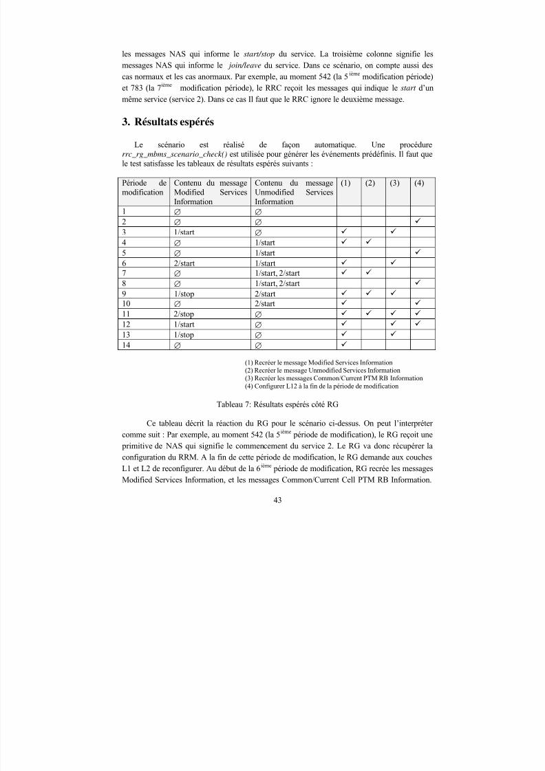
les messages NAS qui informe le start/stop du service. La troisième colonne signifie lesmessages NAS qui informe le join/leave du service. Dans ce scénario, on compte aussi descas normaux et les cas anormaux. Par exemple, au moment 542 (la 5 ième modification période)et 783 (la 7ième modification période), le RRC reçoit les messages qui indique le start d’unmême service (service 2). Dans ce cas Il faut que le RRC ignore le deuxième message.
3. Résultats espérés
Le scénario est réalisé de façon automatique. Une procédurerrc_rg_mbms_scenario_check() est utilisée pour générer les événements prédéfinis. Il faut quele test satisfasse les tableaux de résultats espérés suivants :
Période demodification
Contenu du messageModified ServicesInformation
Contenu du messageUnmodified ServicesInformation
(1) (2) (3) (4)
1 ∅ ∅ 2 ∅ ∅ 3 1/start ∅ 4 ∅ 1/start 5 ∅ 1/start 6 2/start 1/start 7 ∅ 1/start, 2/start 8 ∅ 1/start, 2/start 9 1/stop 2/start 10 ∅ 2/start
11 2/stop ∅ 12 1/start ∅ 13 1/stop ∅ 14 ∅ ∅
(1) Recréer le message Modified Services Information(2) Recréer le message Unmodified Services Information(3) Recréer les messages Common/Current PTM RB Information(4) Configurer L12 à la fin de la période de modification
Tableau 7: Résultats espérés côté RG
Ce tableau décrit la réaction du RG pour le scénario ci-dessus. On peut l’interprétercomme suit : Par exemple, au moment 542 (la 5ième période de modification), le RG reçoit une primitive de NAS qui signifie le commencement du service 2. Le RG va donc récupérer laconfiguration du RRM. A la fin de cette période de modification, le RG demande aux couchesL1 et L2 de reconfigurer. Au début de la 6ième période de modification, RG recrée les messagesModified Services Information, et les messages Common/Current Cell PTM RB Information.
43
8/12/2019 Stage-nguyen Huu Nghia
http://slidepdf.com/reader/full/stage-nguyen-huu-nghia 44/90
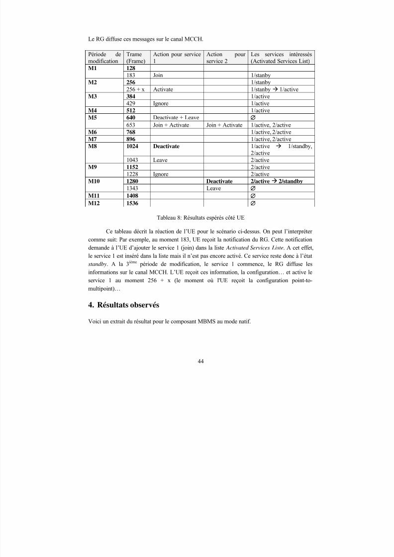
Le RG diffuse ces messages sur le canal MCCH.
Période demodification
Trame(Frame)
Action pour service1
Action pourservice 2
Les services intéressés(Activated Services List)
128M1
183 Join 1/stanby256 1/stanby M2
256 + x Activate 1/stanby 1/active384 1/active M3
429 Ignore 1/activeM4 512 1/active
640 Deactivate + LeaveM5
653 Join + Activate Join + Activate 1/active, 2/activeM6 768 1/active, 2/active
M7 896 1/active, 2/active
1024 Deactivate 1/active 1/standby,2/active
M8
1043 Leave 2/active1152 2/active M9
1228 Ignore 2/active1280 Deactivate 2/active 2/standbyM10
1343 LeaveM11 1408
M12 1536
Tableau 8: Résultats espérés côté UE
Ce tableau décrit la réaction de l’UE pour le scénario ci-dessus. On peut l’interprétercomme suit: Par exemple, au moment 183, UE reçoit la notification du RG. Cette notificationdemande à l’UE d’ajouter le service 1 (join) dans la liste Activated Services Liste. A cet effet,le service 1 est inséré dans la liste mais il n’est pas encore activé. Ce service reste donc à l’étatstandby. A la 3ième période de modification, le service 1 commence, le RG diffuse lesinformations sur le canal MCCH. L’UE reçoit ces information, la configuration… et active leservice 1 au moment 256 + x (le moment où l'UE reçoit la configuration point-to-
multipoint)…
4. Résultats observés
Voici un extrait du résultat pour le composant MBMS au mode natif.
44
8/12/2019 Stage-nguyen Huu Nghia
http://slidepdf.com/reader/full/stage-nguyen-huu-nghia 45/90
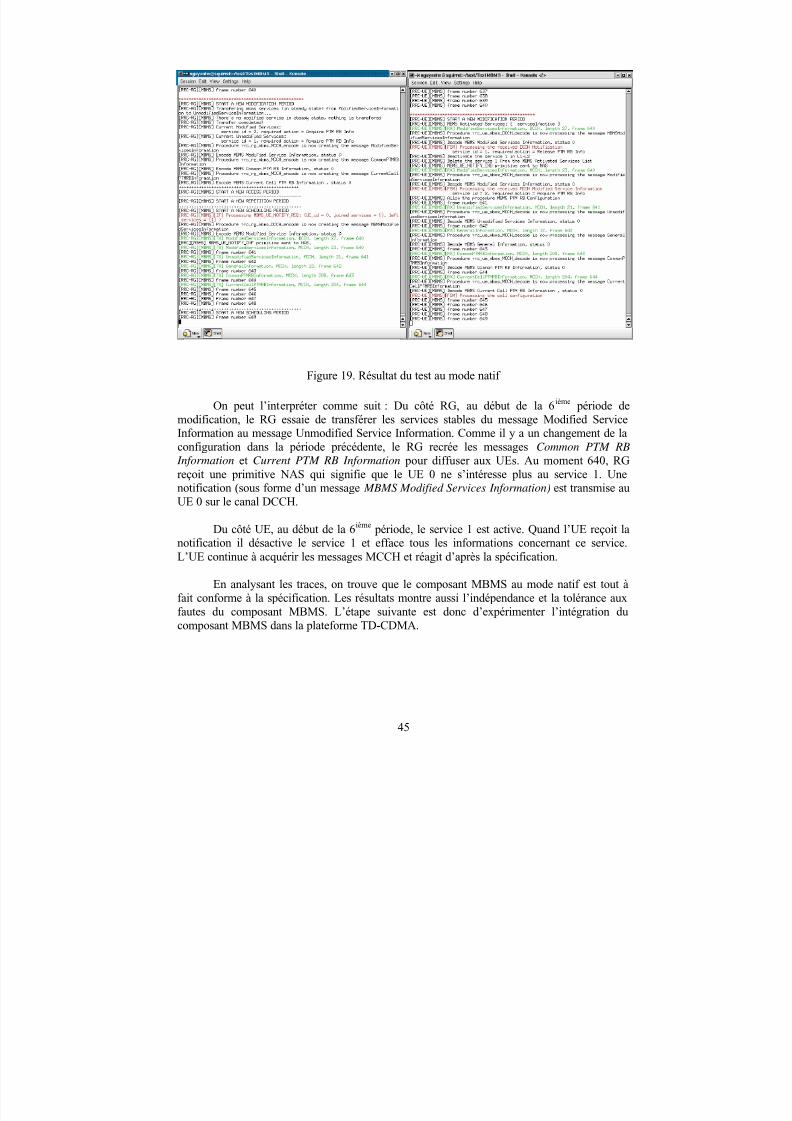
Figure 19. Résultat du test au mode natif
On peut l’interpréter comme suit : Du côté RG, au début de la 6ième période demodification, le RG essaie de transférer les services stables du message Modified ServiceInformation au message Unmodified Service Information. Comme il y a un changement de laconfiguration dans la période précédente, le RG recrée les messages Common PTM RB
Information et Current PTM RB Information pour diffuser aux UEs. Au moment 640, RGreçoit une primitive NAS qui signifie que le UE 0 ne s’intéresse plus au service 1. Unenotification (sous forme d’un message MBMS Modified Services Information) est transmise auUE 0 sur le canal DCCH.
Du côté UE, au début de la 6ième période, le service 1 est active. Quand l’UE reçoit lanotification il désactive le service 1 et efface tous les informations concernant ce service.L’UE continue à acquérir les messages MCCH et réagit d’après la spécification.
En analysant les traces, on trouve que le composant MBMS au mode natif est tout àfait conforme à la spécification. Les résultats montre aussi l’indépendance et la tolérance auxfautes du composant MBMS. L’étape suivante est donc d’expérimenter l’intégration ducomposant MBMS dans la plateforme TD-CDMA.
45
8/12/2019 Stage-nguyen Huu Nghia
http://slidepdf.com/reader/full/stage-nguyen-huu-nghia 46/90
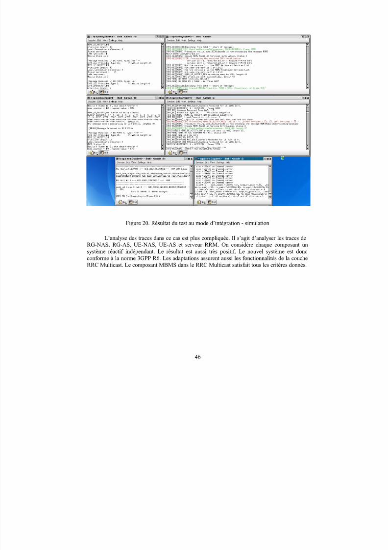
Figure 20. Résultat du test au mode d’intégration - simulation
L’analyse des traces dans ce cas est plus compliquée. Il s’agit d’analyser les traces deRG-NAS, RG-AS, UE-NAS, UE-AS et serveur RRM. On considère chaque composant unsystème réactif indépendant. Le résultat est aussi très positif. Le nouvel système est doncconforme à la norme 3GPP R6. Les adaptations assurent aussi les fonctionnalités de la coucheRRC Multicast. Le composant MBMS dans le RRC Multicast satisfait tous les critères donnés.
46
8/12/2019 Stage-nguyen Huu Nghia
http://slidepdf.com/reader/full/stage-nguyen-huu-nghia 47/90
Conclusions et perspectives
Le problème du broadcast/multicast dans le cadre du projet DAIDALOS convenait parfaitement à un stage de 7 mois. C’est un stage très enrichissant. Dans le cadre du stage, la plate-forme TD-CDMA, le projet DAIDALOS et les documents du 3GPP (la couche RRC, le protocole MBMS,…) sont bien étudiés. L’objectif principal du stage est d’intégrer le
protocole MBMS dans la plate-forme TD-CDMA.
Nous avons synthétisé des documents de spécification, des documents de conception.
Nous avons aussi suivi les comptes-rendu du 3GPP pour proposer une adaptation optimale au protocole MBMS, pour prévoir l’interaction NAS-AS. Nous avons analysé le code source de
la plate-forme TD-CDMA pour découvrir et résoudre certains problèmes potentiels.
Nous avons aussi modélisé le protocole MBMS avec Télélogic Tau. Ensuite, nousavons abordé une implémentation du protocole MBMS qui peut fonctionner dans le modenatif (pour le test) ou dans le mode d’intégration (pour le projet DAIDALOS). Nous avonsréalisé les tests pour valider les adaptations et pour vérifier l’implémentation du MBMS. Lestests donnent des résultats positifs. La couche RRC est donc conforme au 3GPP R6 (au moins
pour la signalisation, la structure des messages, la fonctionalité).
Comme nous l’avons annoncé, l’implémentation se base sur certaines hypothèses.Actuellement, on ne s’intéresse qu’à la validité du protocole MBMS dans le cadre du projetDAIDALOS. La couche L1 et L2 reste encore à la version 3GPP R4 (unicast). Il manque descanaux MTCH, MCCH, MSCH qui sont dédiés aux MBMS. Les mécanismes d’établissementet de relâchement des RBs ne sont pas encore parfaits.
Effectivement, la plateforme logiciel TD-CDMA est déjà utilisée dans plusieurs projetseuropéens comme RHODOS, WIDENS. Maintenant, en restant conforme à la norme 3GPP
R6, elle est bien exploitée dans le projet européen DAIDALOS. Pourtant, afin de compléterces travaux, il faudrait encore continuer des recherches et des développements.
47
8/12/2019 Stage-nguyen Huu Nghia
http://slidepdf.com/reader/full/stage-nguyen-huu-nghia 48/90
Références[1] Michelle Wetterwald, Christian Bonnet, Lionel Gauthier, Yan Moret, Raymond Knopp,
Dominique Nussbaum, An original adaptation of the UMTS protocols for a DirectInterconnection with IPv6
[2] Eurécom, Une plateforme radio logicielle UMTS-TDD[3] Michelle Wetterwald, NAS Interfaces for MBMS (working document) [4] Michelle Wetterwald, Huu Nghia Nguyen, RRC for MBMS (working document)[5] Michelle Wetterwald, Huu Nghia Nguyen, RRC for MBMS conception document
(working document)[6] H.Holma A.Toskala , UMTS les réseaux mobiles de troisième génération, ISBN : 2-
7464-0370-6
[7] Jeffrey Bannister, Paul Mather, Sebastian Coope , Convergence Technologies for 3G Networks: IP, UMTS, EGPRS and ATM, ISBN: 047086091X[8] Guy Pujolle, Olivier Salvatori, Jacques Nozick, Les réseaux, édition 2005, ISBN :
2212114370 [9] David R. Kosiur, IP Multicasting: the Complete Guide to Interactive Corporate
Networks, ISBN: 0471243590[10] Alex Brand, Hamid Aghvami, Multiple access protocols for mobiles communication:
GPRS, UMTS and Beyon, ISBN: 0471498777[11] 3GPP TR 21.905, v6.7.0: "Vocabulary for 3GPP Specifications"[12] 3GPP TR 22.146 v6.6.0: "Multimedia Broadcast/Multicast Service; Stage 1"[13] 3GPP TR 22.946, v1.0.0: "Broadcast and multicast services"[14] 3GPP TS 23.110, v6.0.0: "UMTS Access Stratum Services and Functions"[15] 3GPP TS 23.246, v6.5.0: "Multimedia Broadcast/Multicast Service (MBMS);
Architecture and functional description"[16] 3GPP TR 23.846, v6.1.0: "Multimedia Broadcast/Multicast Service (MBMS); Stage 2"[17] 3GPP TS 25.346, v6.4.0: "Introduction of the Multimedia Broadcast Multicast Service
(MBMS) in the Radio Access Network (RAN); Stage 2"
[18] 3GPP TS 25.331, v6.5.0: "Radio Resource Control (RRC); Protocol Specification(Release 6)"
[19] 3GPP TS 25.301, v6.2.0: "Radio interface protocol architecture (Release 6)"[20] 3GPP TR 25.931, v6.2.0: "UTRAN functions, examples on signalling procedures"[21] 3GPP TS 26.346, v6.2.0: "Multimedia Broadcast/Multicast Service (MBMS); Protocols
and codecs"[22] 3GPP TS 29.846, v6.0.0: "Multimedia Broadcast/Multicast Service (MBMS); CN1
procedure description"
48
8/12/2019 Stage-nguyen Huu Nghia
http://slidepdf.com/reader/full/stage-nguyen-huu-nghia 49/90
[23] ITU-T Recommendation X.210: "Open Systems Interconnection - Basic referencemodel: Conventions for the definition of OSI services"
[24] RFC 1112: "Host extensions for IP multicasting"[25] Alain Charbonnier, Les systèm mobile de troisième génération[26] Alcatel, J. de Vriendt, I. Gómez Vinagre, A. Van Ewijk, Multimedia Broadcast and
Multicast Services in 3G Mobile Networks[27] Mariann Hauge, Oyvind Kure, Multicast in 3G Network : Employment of existing IP
multicast protocols in UMTS[28] L.Henden (ed.), N. Chuberre, L. Combelles, G. Corazza, S. Danton, T. Flo,
D. Grace, T. Kourtis, H. Le-Bihan, H. Linder, A. Nordbotten, E. Pallis,T. Tjelta, A. Vanelli , Broadcast and multicast - a vision on their role in future
broadband access networks [29] Tektronix, W-CDMA/UMTS Wireless Networks: Technology Brief[30] Tektronix, K1297 – G20 Protocol Tester
[31] http://www.equitekcapital.com/Investorinfo/Webpagecontent/flarion_articles/flarioneconomist2.htm[32] http://www.mobilites.net/?2005/03/29/112-linternet-4g-ambiant-et-plus-tard-autonome[33] Christian Claveleira, Diffusion unicast et multicast (http://www.netcast.be/Pour-
Approfondir/Diffusion-unicast-et-multicast.html )[34] IEEE working groups – IEEE 802.xx, http://grouper.ieee.org/groups/802/ [35] Eurécom, www.wireless3G4Free.com[36] Télélogic Tau, www.telelogic.com[37] 3GPP Website, http://www.3gpp.org [38] IPv6 Forum Website, http://www.ipv6forum.org
[39] FP6, http://europa.eu.int/comm/research/fp6/index_en.html[40] DAIDALOS, http://www.ist-daidalos.org
49
8/12/2019 Stage-nguyen Huu Nghia
http://slidepdf.com/reader/full/stage-nguyen-huu-nghia 50/90
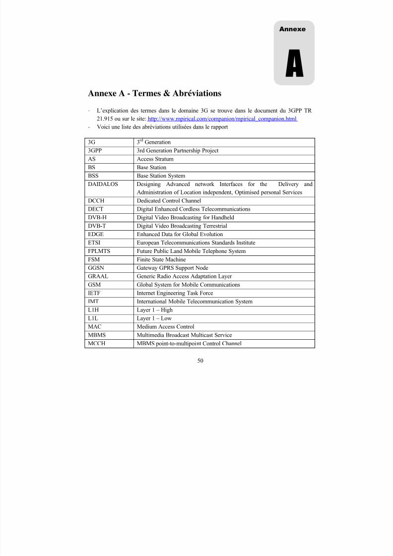
Annexe A - Termes & Abréviations
- L’explication des termes dans le domaine 3G se trouve dans le document du 3GPP TR21.915 ou sur le site: http://www.mpirical.com/companion/mpirical_companion.html
- Voici une liste des abréviations utilisées dans le rapport
3G 3rd Generation
3GPP 3rd Generation Partnership ProjectAS Access Stratum
BS Base Station
BSS Base Station System
DAIDALOS Designing Advanced network Interfaces for the Delivery andAdministration of Location independent, Optimised personal Services
DCCH Dedicated Control Channel
DECT Digital Enhanced Cordless Telecommunications
DVB-H Digital Video Broadcasting for Handheld
DVB-T Digital Video Broadcasting TerrestrialEDGE Enhanced Data for Global Evolution
ETSI European Telecommunications Standards Institute
FPLMTS Future Public Land Mobile Telephone System
FSM Finite State Machine
GGSN Gateway GPRS Support Node
GRAAL Generic Radio Access Adaptation Layer
GSM Global System for Mobile Communications
IETF Internet Engineering Task Force
IMT International Mobile Telecommunication SystemL1H Layer 1 – High
L1L Layer 1 – Low
MAC Medium Access Control
MBMS Multimedia Broadcast Multicast Service
MCCH MBMS point-to-multipoint Control Channel
Annexe
A
50

8/12/2019 Stage-nguyen Huu Nghia
http://slidepdf.com/reader/full/stage-nguyen-huu-nghia 51/90
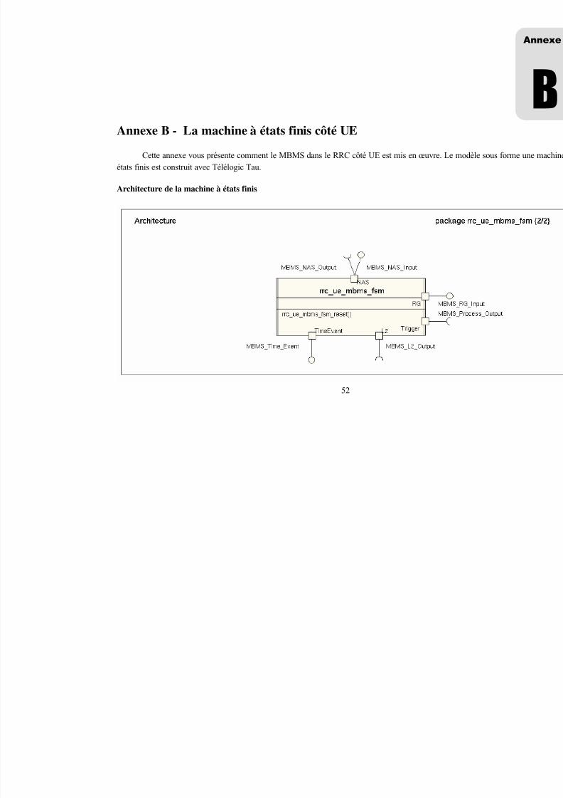
8/12/2019 Stage-nguyen Huu Nghia
http://slidepdf.com/reader/full/stage-nguyen-huu-nghia 52/90
Annexe B - La machine à états finis côté UE
Cette annexe vous présente comment le MBMS dans le RRC côté UE est mis en œuvre. Le mod
états finis est construit avec Télélogic Tau.
Architecture de la machine à états finis
52
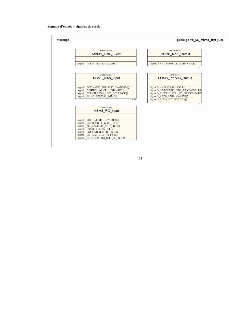
8/12/2019 Stage-nguyen Huu Nghia
http://slidepdf.com/reader/full/stage-nguyen-huu-nghia 53/90
Signaux d’entrée – signaux de sortie
53
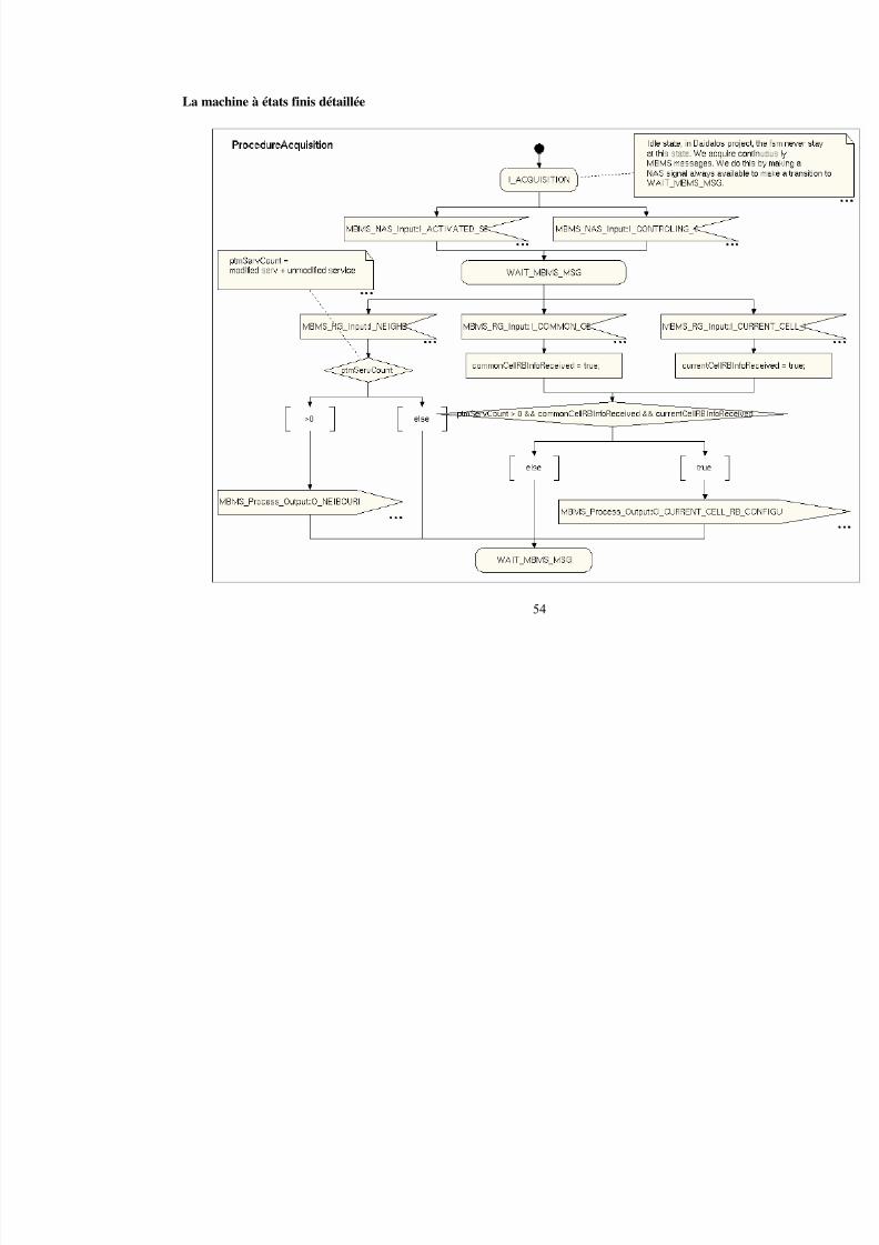
8/12/2019 Stage-nguyen Huu Nghia
http://slidepdf.com/reader/full/stage-nguyen-huu-nghia 54/90
La machine à états finis détaillée
54
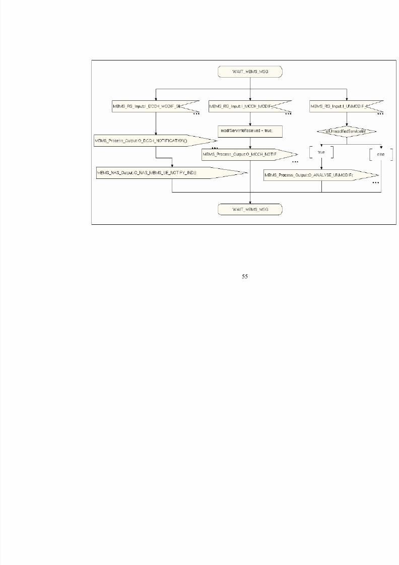
8/12/2019 Stage-nguyen Huu Nghia
http://slidepdf.com/reader/full/stage-nguyen-huu-nghia 55/90
55
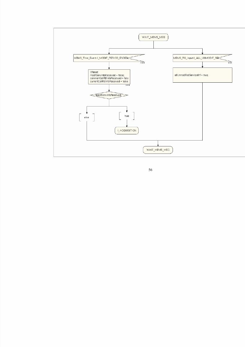
8/12/2019 Stage-nguyen Huu Nghia
http://slidepdf.com/reader/full/stage-nguyen-huu-nghia 56/90
56
8/12/2019 Stage-nguyen Huu Nghia
http://slidepdf.com/reader/full/stage-nguyen-huu-nghia 57/90
Annexe C – Document de spécification (Anglais)
RRC for MBMS
Working Document – Printed 06/12/2005
Michelle WETTERWALDHuu Nghia NGUYEN
Mobile Communication DepartmentInstitut Eurecom
BP 193F-06904 Sophia Antipolis Cedex - France
Tel: 04.93.00.26.31 - Fax: 04.93.00 26.27
Email : [email protected] web : http://www.eurecom..fr/Mobile
Annexe
C
57
8/12/2019 Stage-nguyen Huu Nghia
http://slidepdf.com/reader/full/stage-nguyen-huu-nghia 58/90
1. Introduction
This part describes the RRC protocol layer for MBMS. This is a reduced version of theoriginal working document. References used in this part are locally relative to TS 25.331. For
example: [6.3] means the section 6.3 of the TS 25.331 document.
2. Signalling Radio Bearers [6.3]
The Radio Bearers (RB) available for transmission of RRC messages are defined as
"signalling radio bearers" and are specified in the following. The UE and UTRAN shall select thesignalling radio bearers for RRC messages using RLC-TM, RLC-UM or RLC-AM on the DCCH
and CCCH, according to the following:
5. Signalling radio bearer RB0 shall be used for all messages sent on the CCCH (UL: RLC-TM,DL: RLC-UM).
6. Signalling radio bearer RB1 shall be used for all messages sent on the DCCH, when usingRLC unacknowledged mode (RLC-UM).
7. Signalling radio bearer RB2 shall be used for all messages sent on the DCCH, when usingRLC acknowledged mode (RLC-AM), except for the RRC messages carrying higher layer
(NAS) signalling.8. Signalling radio bearer RB3 and optionally Signalling radio bearer RB4 shall be used for the
RRC messages carrying higher layer (NAS) signalling and sent on the DCCH in RLCacknowledged mode (RLC-AM), as specified in subclauses 8.1.8., 8.1.9 and 8.1.10.
9. Additionally, RBs whose identities shall be set between 5 and 32 may be used as signallingradio bearer for the RRC messages on the DCCH sent in RLC transparent mode (RLC-TM).
10. RRC messages on the MCCH are mapped on FACH using RLC-UM. The transport channelconfiguration for MCCH is indicated on BCCH. For this signalling radio bearer no identity isapplied.
11. RRC messages on the MSCH are mapped on FACH using RLC-UM. The transport channelconfiguration for MSCH is indicated on MCCH. For this signalling radio bearer no identity isapplied.
3. External Interfaces
58
8/12/2019 Stage-nguyen Huu Nghia
http://slidepdf.com/reader/full/stage-nguyen-huu-nghia 59/90
3.1. Primitives for the interface with the NAS (To be updated by MW)
3.2. RRC Peer-to-peer - MBMS specific procedures
3.2.1. MCCH Acquisition
Purpose:
The UE applies the MCCH acquisition procedure to determine the MBMS servicesavailable in the cell and to initiate reception of the services that the UE has joined. The procedureapplies to all UEs supporting MBMS, irrespective of their state (idle, URA_PCH, CELL_PCH,CELL_FACH and CELL_DCH).
Associated RRC Messages:
UTRAN→ UE
MBMS MODIFIED SERVICES INFORMATIONMBMS UNMODIFIED SERVICES INFORMATIONMBMS ACCESS INFORMATIONGENERAL INFORMATIONMBMS CURRENT CELL P-T-M RB INFORMATIONMBMS NEIGHBOURING CELL P-T-M RB INFORMATION
RLC-SAP: UMLogical channel: MCCH
3.2.2. MBMS Notification
Purpose:
The MBMS notification procedure is used by the UE to respond to a notification provided by UTRAN, indicating a change applicable for one or more MBMS services the UE has joined.The procedure applies to all UEs supporting MBMS, irrespective of their state (idle andconnected mode: URA_PCH, CELL_PCH, CELL_FACH and CELL_DCH). The actual
notification mechanism to be used depends on the UE state.
Associated RRC Messages:
In case of notification on the DCCH
UTRAN→ UE – MBMS MODIFIED SERVICES INFORMATION
RLC-SAP: UMLogical channel: DCCH
UTRAN→ UE – Updated MBMS control information (Other MBMS messages ?)
RLC-SAP: UM
59
8/12/2019 Stage-nguyen Huu Nghia
http://slidepdf.com/reader/full/stage-nguyen-huu-nghia 60/90
Logical channel: MCCH
3.2.3. MBMS counting – message supported only
Purpose:
The MBMS counting procedure is used by the UE to inform UTRAN about its interest toreceive an MBMS transmission. The procedure applies to UEs supporting MBMS that are in idle
mode or in connected mode, URA_PCH state.
Associated RRC Messages:
UTRAN→ UE - MBMS ACCESS INFORMATION
RLC-SAP: UMLogical channel: MCCH
3.2.4. MBMS p-t-m radio bearer configuration
Purpose:
The MBMS p-t-m radio bearer configuration procedure is used by the UE to acquire the(modified) radio bearer configuration for one or more MBMS services the UE has joined. The procedure applies to all UEs supporting MBMS, irrespective of their state (idle and connectedmode: URA_PCH, CELL_PCH, CELL_FACH and CELL_DCH).
Associated RRC Messages:
UTRAN→ UE - MBMS COMMON P-T-M RB INFORMATION
RLC-SAP: UMLogical channel: MCCH
UTRAN→ UE - MBMS CURRENT CELL P-T-M RB INFORMATION
RLC-SAP: UMLogical channel: MCCH
UTRAN→ UE - MBMS NEIGHBOURING CELL P-T-M RB INFORMATION
RLC-SAP: UM
Logical channel: MCCH
3.2.5. MBMS modification request – not supported
Purpose:
The MBMS modification request procedure is used by the UE to request UTRAN torelease the p-t-p radio bearers of one or more MBMS services the UE is receiving. The procedure
60

8/12/2019 Stage-nguyen Huu Nghia
http://slidepdf.com/reader/full/stage-nguyen-huu-nghia 61/90
may also be used to request to be moved to a preferred frequency applicable for one or more(prioritised) MBMS services, the UE has joined. The procedure applies to all UEs supporting
MBMS, that are in state CELL_DCH.
Associated RRC Messages:
UE→ UTRAN - MBMS MODIFICATION REQUEST
RLC-SAP: UM ?Logical channel: DCCH
3.2.6. MBMS service scheduling
Purpose:
The MBMS service scheduling procedure is used by the UE that is receiving one or more
MBMS services that the UE has joined to acquire the MBMS scheduling information for theMBMS services. The procedure applies to all UEs that are receiving an MBMS service providedvia a p-t-m radio bearer, irrespective of their state (idle and connected mode: URA_PCH,CELL_PCH, CELL_FACH and CELL_DCH).
Associated RRC Messages:
UTRAN→ UE - MBMS SCHEDULING INFORMATION
RLC-SAP: UMLogical channel: MSCH
4. Internal Procedures Description-MBMS specific procedures
MBMS specific procedure include the following procedures:
MCCH acquisition: The UE applies the MCCH acquisition procedure to determine theMBMS services available in the cell and to initiate reception of the services that the UE has joined. The procedure applies to all UEs supporting MBMS, irrespective of their state (idle,URA_PCH, CELL_PCH, CELL_FACH and CELL_DCH).
MBMS Notification: The MBMS notification procedure is used by the UE to respond to anotification provided by UTRAN, indicating a change applicable for one or more MBMSservices the UE has joined. The procedure applies to all UEs supporting MBMS, irrespectiveof their state (idle and connected mode: URA_PCH, CELL_PCH, CELL_FACH andCELL_DCH). The actual notification mechanism to be used depends on the UE state.
MBMS p-t-m radio bearer configuration: The MBMS p-t-m radio bearer configuration procedure is used by the UE to acquire the (modified) radio bearer configuration for one or
61
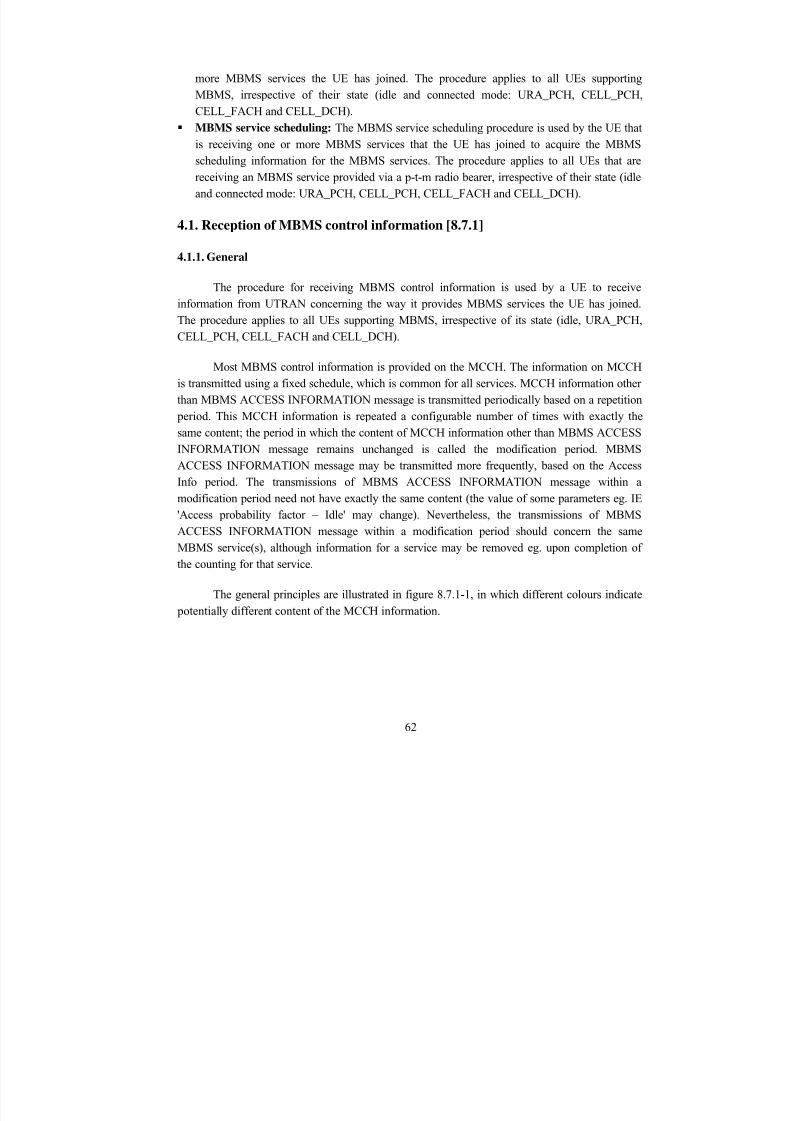
8/12/2019 Stage-nguyen Huu Nghia
http://slidepdf.com/reader/full/stage-nguyen-huu-nghia 62/90
more MBMS services the UE has joined. The procedure applies to all UEs supportingMBMS, irrespective of their state (idle and connected mode: URA_PCH, CELL_PCH,CELL_FACH and CELL_DCH).
MBMS service scheduling: The MBMS service scheduling procedure is used by the UE thatis receiving one or more MBMS services that the UE has joined to acquire the MBMSscheduling information for the MBMS services. The procedure applies to all UEs that arereceiving an MBMS service provided via a p-t-m radio bearer, irrespective of their state (idleand connected mode: URA_PCH, CELL_PCH, CELL_FACH and CELL_DCH).
4.1. Reception of MBMS control information [8.7.1]
4.1.1. General
The procedure for receiving MBMS control information is used by a UE to receive
information from UTRAN concerning the way it provides MBMS services the UE has joined.The procedure applies to all UEs supporting MBMS, irrespective of its state (idle, URA_PCH,CELL_PCH, CELL_FACH and CELL_DCH).
Most MBMS control information is provided on the MCCH. The information on MCCHis transmitted using a fixed schedule, which is common for all services. MCCH information otherthan MBMS ACCESS INFORMATION message is transmitted periodically based on a repetition period. This MCCH information is repeated a configurable number of times with exactly thesame content; the period in which the content of MCCH information other than MBMS ACCESS
INFORMATION message remains unchanged is called the modification period. MBMSACCESS INFORMATION message may be transmitted more frequently, based on the AccessInfo period. The transmissions of MBMS ACCESS INFORMATION message within amodification period need not have exactly the same content (the value of some parameters eg. IE'Access probability factor – Idle' may change). Nevertheless, the transmissions of MBMSACCESS INFORMATION message within a modification period should concern the sameMBMS service(s), although information for a service may be removed eg. upon completion ofthe counting for that service.
The general principles are illustrated in figure 8.7.1-1, in which different colours indicate
potentially different content of the MCCH information.
62
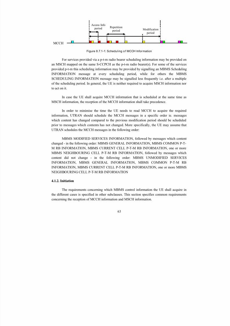
8/12/2019 Stage-nguyen Huu Nghia
http://slidepdf.com/reader/full/stage-nguyen-huu-nghia 63/90
Modification period
Access Info period Repetition
period
MCCH
Figure 8.7.1-1: Schedul ing o f MCCH Information
For services provided via a p-t-m radio bearer scheduling information may be provided onan MSCH mapped on the same S-CCPCH as the p-t-m radio bearer(s). For some of the services provided p-t-m this scheduling information may be provided by signalling an MBMS SchedulingINFORMATION message at every scheduling period, while for others the MBMSSCHEDULING INFORMATION message may be signalled less frequently i.e. after a multipleof the scheduling period. In general, the UE is neither required to acquire MSCH information nor
to act on it.
In case the UE shall acquire MCCH information that is scheduled at the same time asMSCH information, the reception of the MCCH information shall take precedence.
In order to minimise the time the UE needs to read MCCH to acquire the requiredinformation, UTRAN should schedule the MCCH messages in a specific order ie. messageswhich content has changed compared to the previous modification period should be scheduled prior to messages which contents has not changed. More specifically, the UE may assume that
UTRAN schedules the MCCH messages in the following order:
MBMS MODIFIED SERVICES INFORMATION, followed by messages which contentchanged - in the following order: MBMS GENERAL INFORMATION, MBMS COMMON P-T-M RB INFORMATION, MBMS CURRENT CELL P-T-M RB INFORMATION, one or moreMBMS NEIGHBOURING CELL P-T-M RB INFORMATION, followed by messages whichcontent did not change - in the following order: MBMS UNMODIFIED SERVICESINFORMATION, MBMS GENERAL INFORMATION, MBMS COMMON P-T-M RBINFORMATION, MBMS CURRENT CELL P-T-M RB INFORMATION, one or more MBMS
NEIGHBOURING CELL P-T-M RB INFORMATION
4.1.2. Initiation
The requirements concerning which MBMS control information the UE shall acquire inthe different cases is specified in other subclauses. This section specifies common requirementsconcerning the reception of MCCH information and MSCH information.
63
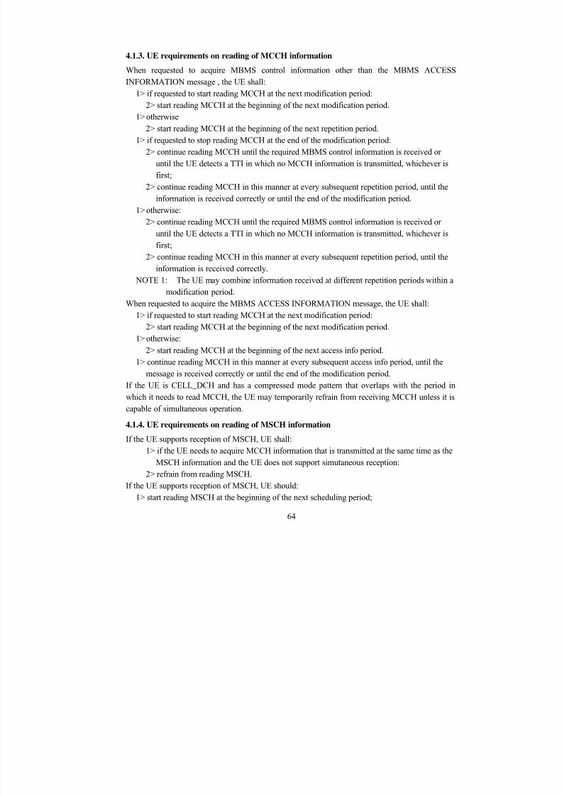
8/12/2019 Stage-nguyen Huu Nghia
http://slidepdf.com/reader/full/stage-nguyen-huu-nghia 64/90
4.1.3. UE requirements on reading of MCCH information
When requested to acquire MBMS control information other than the MBMS ACCESSINFORMATION message , the UE shall:
1> if requested to start reading MCCH at the next modification period:
2> start reading MCCH at the beginning of the next modification period.1> otherwise2> start reading MCCH at the beginning of the next repetition period.
1> if requested to stop reading MCCH at the end of the modification period:2> continue reading MCCH until the required MBMS control information is received or
until the UE detects a TTI in which no MCCH information is transmitted, whichever isfirst;
2> continue reading MCCH in this manner at every subsequent repetition period, until theinformation is received correctly or until the end of the modification period.
1> otherwise:2> continue reading MCCH until the required MBMS control information is received or
until the UE detects a TTI in which no MCCH information is transmitted, whichever isfirst;
2> continue reading MCCH in this manner at every subsequent repetition period, until theinformation is received correctly.
NOTE 1: The UE may combine information received at different repetition periods within amodification period.
When requested to acquire the MBMS ACCESS INFORMATION message, the UE shall:1> if requested to start reading MCCH at the next modification period:
2> start reading MCCH at the beginning of the next modification period.1> otherwise:
2> start reading MCCH at the beginning of the next access info period.1> continue reading MCCH in this manner at every subsequent access info period, until the
message is received correctly or until the end of the modification period.If the UE is CELL_DCH and has a compressed mode pattern that overlaps with the period inwhich it needs to read MCCH, the UE may temporarily refrain from receiving MCCH unless it iscapable of simultaneous operation.
4.1.4. UE requirements on reading of MSCH information
If the UE supports reception of MSCH, UE shall:1> if the UE needs to acquire MCCH information that is transmitted at the same time as the
MSCH information and the UE does not support simutaneous reception:2> refrain from reading MSCH.
If the UE supports reception of MSCH, UE should:1> start reading MSCH at the beginning of the next scheduling period;
64
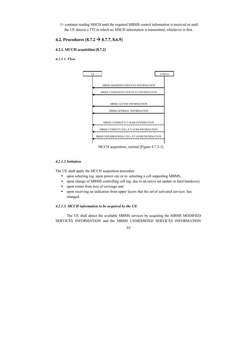
8/12/2019 Stage-nguyen Huu Nghia
http://slidepdf.com/reader/full/stage-nguyen-huu-nghia 65/90
1> continue reading MSCH until the required MBMS control information is received or untilthe UE detects a TTI in which no MSCH information is transmitted, whichever is first.
4.2. Procedures [8.7.2 8.7.7, 8.6.9]
4.2.1. MCCH acquisition [8.7.2]
4.2.1.1. Flow
UTRAN
MBMS MODIFIED SERVICES INFORMATION
UE
MBMS UNMODIFIED SERVICES INFORMATION
MBMS GENERAL INFORMATION
MBMS COMMON P-T-M RB INFORMATION
MBMS CURRENT CELL P-T-M RB INFORMATION
MBMS NEIGHBOURING CELL P-T-M RB INFORMATION
MBMS ACCESS INFORMATION
MCCH acquisition, normal [Figure 8.7.2-1]
4.2.1.2 Initiation
The UE shall apply the MCCH acquisition procedure upon selecting (eg. upon power on) or re- selecting a cell supporting MBMS, upon change of MBMS controlling cell (eg. due to an active set update or hard handover), upon return from loss of coverage and
upon receiving an indication from upper layers that the set of activated services haschanged.
4.2.1.3. MCCH information to be acquired by the UE
The UE shall detect the available MBMS services by acquiring the MBMS MODIFIEDSERVICES INFORMATION and the MBMS UNMODIFIED SERVICES INFORMATION
65

8/12/2019 Stage-nguyen Huu Nghia
http://slidepdf.com/reader/full/stage-nguyen-huu-nghia 66/90
messages without delaying reading of MCCH until the next modification period and without
stopping at the end of the modification period, in accordance with subclause 8.7.1.3.
The UE shall immediately acquire the MBMS ACCESS INFORMATION and the MBMSGENERAL INFORMATION messages ie. it shall not delay reception of these messages until it
has completed the acquisition of the MBMS MODIFIED SERVICES INFORMATION and theMBMS UNMODIFIED SERVICES INFORMATION messages. Likewise, the UE shouldimmediately acquire the MBMS CURRENT CELL P-T-M RB INFORMATION and MBMS NEIGHBOURING CELL P-T-M RB INFORMATION messages.
The UE shall continue acquiring the above messages until it has received a consistent set ofMCCH information eg. both the MBMS MODIFIED SERVICES INFORMATION and theMBMS UNMODIFIED SERVICES INFORMATION message should be acquired in the samemodification period.
4.2.1.4. Reception of the MODIFIED SERVICES INFORMATION and the MBMS
UNMODIFIED SERVICES INFORMATION by the UE
Upon completing the reception of the MODIFIED SERVICES INFORMATION and the MBMSUNMODIFIED SERVICES INFORMATION messages, the UE shall
1> act as follows for each of the services included in these messages provided that the serviceis included in variable MBMS_ACTIVATED_SERVICES and upper layers indicate thatthe session has not yet been received correctly (referred to as 'applicable services');
1> act upon all received information elements as specified in subclause 8.6, unless specifiedotherwise in the following;
1> perform the service prioritisation procedure as specified in subclause 8.5.26;1> if the UE receives an MBMS service using a p-t-m radio bearer and the received messages
does not contain an IE "MBMS required action" set to "Acquire PTM RB info" for thatservice then the UE shall:2> stop receiving the concerned MBMS service and clear all service specific information
applicable for the concerned service.
4.2.1.5. Reception of the other MBMS messages by the UE
Upon receiving the MBMS ACCESS INFORMATION message, the UE shall act as specified insubclause 8.7.4.3.Upon receiving the MBMS GENERAL INFORMATION message, the UE should store allrelevant IEs included in this message. The UE shall also:
66
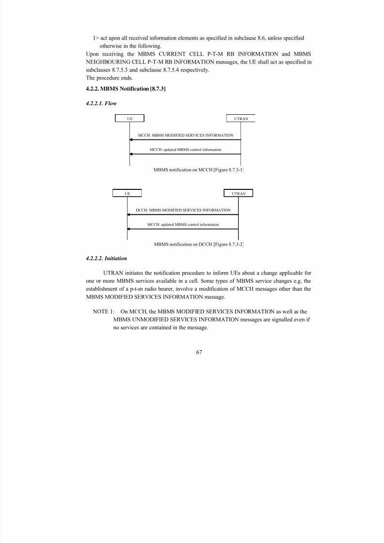
8/12/2019 Stage-nguyen Huu Nghia
http://slidepdf.com/reader/full/stage-nguyen-huu-nghia 67/90
1> act upon all received information elements as specified in subclause 8.6, unless specifiedotherwise in the following.
Upon receiving the MBMS CURRENT CELL P-T-M RB INFORMATION and MBMS NEIGHBOURING CELL P-T-M RB INFORMATION messages, the UE shall act as specified insubclauses 8.7.5.3 and subclause 8.7.5.4 respectively.The procedure ends.
4.2.2. MBMS Notification [8.7.3]
4.2.2.1. Flow
UTRAN
MCCH: MBMS MODIFIED SERVICES INFORMATION
UE
MCCH: updated MBMS control information
MBMS notification on MCCH [Figure 8.7.3-1]
UTRAN
DCCH: MBMS MODIFIED SERVICES INFORMATION
MCCH: updated MBMS control information
UE
MBMS notification on DCCH [Figure 8.7.3-2]
4.2.2.2. Initiation
UTRAN initiates the notification procedure to inform UEs about a change applicable forone or more MBMS services available in a cell. Some types of MBMS service changes e.g. theestablishment of a p-t-m radio bearer, involve a modification of MCCH messages other than the
MBMS MODIFIED SERVICES INFORMATION message.
NOTE 1: On MCCH, the MBMS MODIFIED SERVICES INFORMATION as well as theMBMS UNMODIFIED SERVICES INFORMATION messages are signalled even ifno services are contained in the message.
67
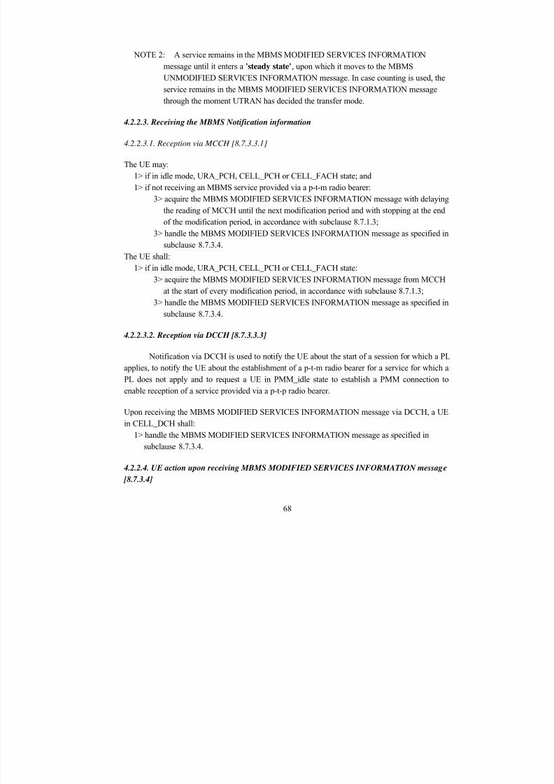
8/12/2019 Stage-nguyen Huu Nghia
http://slidepdf.com/reader/full/stage-nguyen-huu-nghia 68/90
NOTE 2: A service remains in the MBMS MODIFIED SERVICES INFORMATIONmessage until it enters a 'steady state', upon which it moves to the MBMSUNMODIFIED SERVICES INFORMATION message. In case counting is used, theservice remains in the MBMS MODIFIED SERVICES INFORMATION messagethrough the moment UTRAN has decided the transfer mode.
4.2.2.3. Receiving the MBMS Notification information
4.2.2.3.1. Reception via MCCH [8.7.3.3.1]
The UE may:1> if in idle mode, URA_PCH, CELL_PCH or CELL_FACH state; and1> if not receiving an MBMS service provided via a p-t-m radio bearer:
3> acquire the MBMS MODIFIED SERVICES INFORMATION message with delaying
the reading of MCCH until the next modification period and with stopping at the endof the modification period, in accordance with subclause 8.7.1.3;
3> handle the MBMS MODIFIED SERVICES INFORMATION message as specified insubclause 8.7.3.4.
The UE shall:1> if in idle mode, URA_PCH, CELL_PCH or CELL_FACH state:
3> acquire the MBMS MODIFIED SERVICES INFORMATION message from MCCHat the start of every modification period, in accordance with subclause 8.7.1.3;
3> handle the MBMS MODIFIED SERVICES INFORMATION message as specified in
subclause 8.7.3.4.
4.2.2.3.2. Reception via DCCH [8.7.3.3.3]
Notification via DCCH is used to notify the UE about the start of a session for which a PLapplies, to notify the UE about the establishment of a p-t-m radio bearer for a service for which aPL does not apply and to request a UE in PMM_idle state to establish a PMM connection toenable reception of a service provided via a p-t-p radio bearer.
Upon receiving the MBMS MODIFIED SERVICES INFORMATION message via DCCH, a UE
in CELL_DCH shall:1> handle the MBMS MODIFIED SERVICES INFORMATION message as specified in
subclause 8.7.3.4.
4.2.2.4. UE action upon receiving MBMS MODIFIED SERVICES INFORMATION message
[8.7.3.4]
68
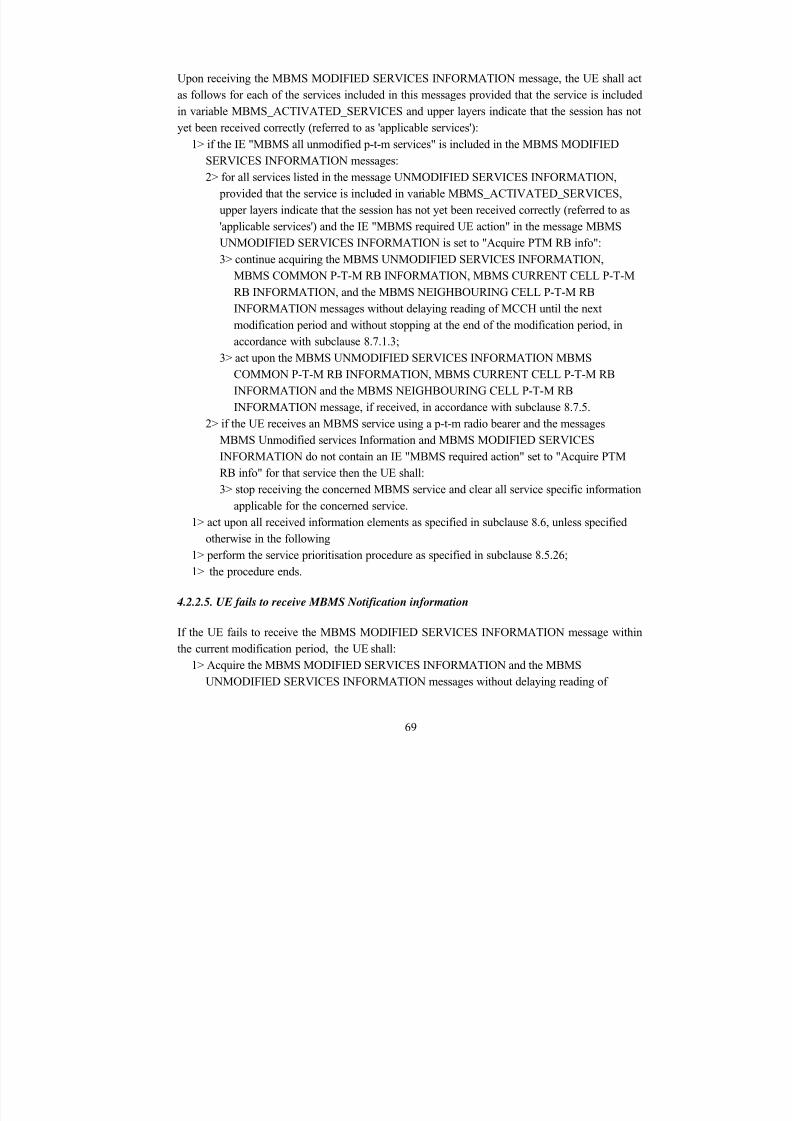
8/12/2019 Stage-nguyen Huu Nghia
http://slidepdf.com/reader/full/stage-nguyen-huu-nghia 69/90
Upon receiving the MBMS MODIFIED SERVICES INFORMATION message, the UE shall actas follows for each of the services included in this messages provided that the service is includedin variable MBMS_ACTIVATED_SERVICES and upper layers indicate that the session has notyet been received correctly (referred to as 'applicable services'):
1> if the IE "MBMS all unmodified p-t-m services" is included in the MBMS MODIFIEDSERVICES INFORMATION messages:2> for all services listed in the message UNMODIFIED SERVICES INFORMATION,
provided that the service is included in variable MBMS_ACTIVATED_SERVICES,upper layers indicate that the session has not yet been received correctly (referred to as'applicable services') and the IE "MBMS required UE action" in the message MBMSUNMODIFIED SERVICES INFORMATION is set to "Acquire PTM RB info":3> continue acquiring the MBMS UNMODIFIED SERVICES INFORMATION,
MBMS COMMON P-T-M RB INFORMATION, MBMS CURRENT CELL P-T-MRB INFORMATION, and the MBMS NEIGHBOURING CELL P-T-M RB
INFORMATION messages without delaying reading of MCCH until the nextmodification period and without stopping at the end of the modification period, inaccordance with subclause 8.7.1.3;
3> act upon the MBMS UNMODIFIED SERVICES INFORMATION MBMSCOMMON P-T-M RB INFORMATION, MBMS CURRENT CELL P-T-M RBINFORMATION and the MBMS NEIGHBOURING CELL P-T-M RBINFORMATION message, if received, in accordance with subclause 8.7.5.
2> if the UE receives an MBMS service using a p-t-m radio bearer and the messagesMBMS Unmodified services Information and MBMS MODIFIED SERVICES
INFORMATION do not contain an IE "MBMS required action" set to "Acquire PTMRB info" for that service then the UE shall:3> stop receiving the concerned MBMS service and clear all service specific information
applicable for the concerned service.1> act upon all received information elements as specified in subclause 8.6, unless specified
otherwise in the following1> perform the service prioritisation procedure as specified in subclause 8.5.26;1> the procedure ends.
4.2.2.5. UE fails to receive MBMS Notification information
If the UE fails to receive the MBMS MODIFIED SERVICES INFORMATION message withinthe current modification period, the UE shall:
1> Acquire the MBMS MODIFIED SERVICES INFORMATION and the MBMSUNMODIFIED SERVICES INFORMATION messages without delaying reading of
69
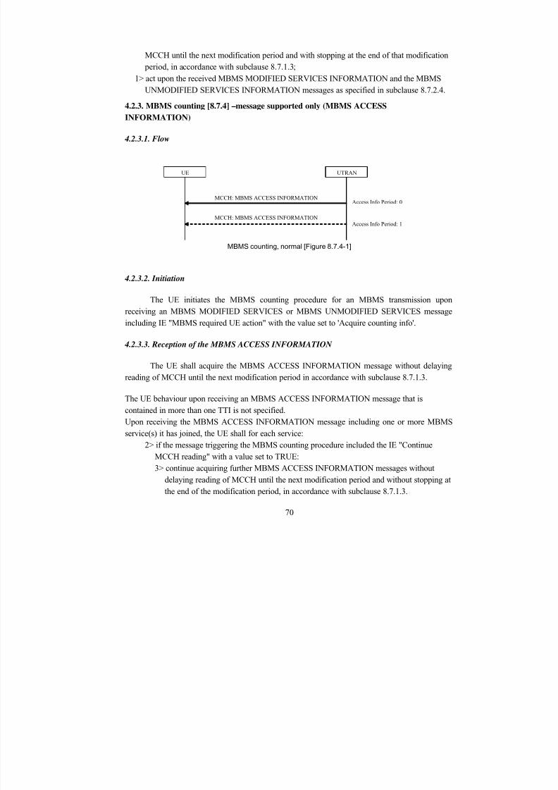
8/12/2019 Stage-nguyen Huu Nghia
http://slidepdf.com/reader/full/stage-nguyen-huu-nghia 70/90
MCCH until the next modification period and with stopping at the end of that modification period, in accordance with subclause 8.7.1.3;
1> act upon the received MBMS MODIFIED SERVICES INFORMATION and the MBMSUNMODIFIED SERVICES INFORMATION messages as specified in subclause 8.7.2.4.
4.2.3. MBMS counting [8.7.4] –message supported only (MBMS ACCESSINFORMATION)
4.2.3.1. Flow
UTRAN
MCCH: MBMS ACCESS INFORMATION
MCCH: MBMS ACCESS INFORMATION
UE
Access Info Period: 0
Access Info Period: 1
MBMS counting, normal [Figure 8.7.4-1]
4.2.3.2. Initiation
The UE initiates the MBMS counting procedure for an MBMS transmission uponreceiving an MBMS MODIFIED SERVICES or MBMS UNMODIFIED SERVICES message
including IE "MBMS required UE action" with the value set to 'Acquire counting info'.
4.2.3.3. Reception of the MBMS ACCESS INFORMATION
The UE shall acquire the MBMS ACCESS INFORMATION message without delayingreading of MCCH until the next modification period in accordance with subclause 8.7.1.3.
The UE behaviour upon receiving an MBMS ACCESS INFORMATION message that iscontained in more than one TTI is not specified.Upon receiving the MBMS ACCESS INFORMATION message including one or more MBMSservice(s) it has joined, the UE shall for each service:
2> if the message triggering the MBMS counting procedure included the IE "ContinueMCCH reading" with a value set to TRUE:3> continue acquiring further MBMS ACCESS INFORMATION messages without
delaying reading of MCCH until the next modification period and without stopping atthe end of the modification period, in accordance with subclause 8.7.1.3.
70
8/12/2019 Stage-nguyen Huu Nghia
http://slidepdf.com/reader/full/stage-nguyen-huu-nghia 71/90
2> otherwise:
3> continue acquiring further MBMS ACCESS INFORMATION messages withoutdelaying reading of MCCH until the next modification period and with stopping atthe end of the modification period, in accordance with subclause 8.7.1.3.
4.2.3.4. Termination of the MBMS counting procedure [8.7.4.4]
If the UE detects that the MBMS ACCESS INFORMATION message is not provided at anaccess info period; ORIf the UE receives an MBMS ACCESS INFORMATION message not including an MBMSservice the UE has joined, the UE shall:
1> terminate the MBMS counting procedure.
4.2.3.5. Failure of the counting response procedure [8.7.4.5]
If the counting response procedure (RRC connection establishment or Cell update) fails, the UEshall:
1> if the failure occurs in the same modification period as the one in which the UE initiated thecounting response procedure; or
1> if the message triggering the MBMS counting procedure included the IE "Continue MCCHreading" with a value set to TRUE that is applicable in the modification period in which theUE detects the failure:2> continue acquiring further MBMS ACCESS INFORMATION messages without
delaying reading of MCCH until the next modification period and without stopping atthe end of the modification period, in accordance with subclause 8.7.1.3.
1> otherwise:2> the procedure ends.
4.2.4. MBMS p-t-m radio bearer configuration [8.7.5]
4.2.4.1. Flow
71
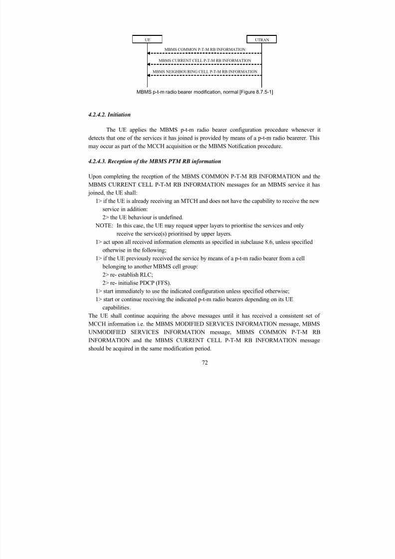
8/12/2019 Stage-nguyen Huu Nghia
http://slidepdf.com/reader/full/stage-nguyen-huu-nghia 72/90
UTRANUE
MBMS COMMON P-T-M RB INFORMATION
MBMS CURRENT CELL P-T-M RB INFORMATION
MBMS NEIGHBOURING CELL P-T-M RB INFORMATION
MBMS p-t-m radio bearer modification, normal [Figure 8.7.5-1]
4.2.4.2. Initiation
The UE applies the MBMS p-t-m radio bearer configuration procedure whenever itdetects that one of the services it has joined is provided by means of a p-t-m radio bearerer. Thismay occur as part of the MCCH acquisition or the MBMS Notification procedure.
4.2.4.3. Reception of the MBMS PTM RB information
Upon completing the reception of the MBMS COMMON P-T-M RB INFORMATION and theMBMS CURRENT CELL P-T-M RB INFORMATION messages for an MBMS service it has joined, the UE shall:
1> if the UE is already receiving an MTCH and does not have the capability to receive the newservice in addition:2> the UE behaviour is undefined.
NOTE: In this case, the UE may request upper layers to prioritise the services and onlyreceive the service(s) prioritised by upper layers.
1> act upon all received information elements as specified in subclause 8.6, unless specifiedotherwise in the following;
1> if the UE previously received the service by means of a p-t-m radio bearer from a cell belonging to another MBMS cell group:2> re- establish RLC;2> re- initialise PDCP (FFS).
1> start immediately to use the indicated configuration unless specified otherwise;
1> start or continue receiving the indicated p-t-m radio bearers depending on its UEcapabilities.The UE shall continue acquiring the above messages until it has received a consistent set ofMCCH information i.e. the MBMS MODIFIED SERVICES INFORMATION message, MBMSUNMODIFIED SERVICES INFORMATION message, MBMS COMMON P-T-M RBINFORMATION and the MBMS CURRENT CELL P-T-M RB INFORMATION messageshould be acquired in the same modification period.
72
8/12/2019 Stage-nguyen Huu Nghia
http://slidepdf.com/reader/full/stage-nguyen-huu-nghia 73/90
4.2.4.4. Reception of the MBMS Neighbour Cell PTM RB information
Upon receiving the MBMS NEIGHBOURING CELL P-T-M RB INFORMATION message for
an MBMS service it has joined, the UE shall1> start immediately to use the indicated neighbouring cells and configuration, or a subset of
them, for L1- or L2 combining unless specified otherwise;1> start or continue receiving the indicated p-t-m radio bearers from the selected neighbouring
cells depending on its UE capabilities, TBS.The UE shall apply MBMS NEIGHBOURING CELL P-T-M RB INFORMATION only incombination with an MBMS MODIFIED SERVICES INFORMATION message, MBMSUNMODIFIED SERVICES INFORMATION message, MBMS COMMON P-T-M RBINFORMATION and MBMS CURRENT CELL P-T-M RB INFORMATION message acquired
in the same modification period.The procedure ends.
4.2.4.5. Service prioritisation [8.5.26]
The UE may perform the Service prioritisation procedure whenever it detects that it becomesincapable of receiving all services it is interested in as well as whenever there are changesconcerning the subset of services that it has selected to receive. This may occur upon statetransitions, service start, service stop, service reconfiguration eg. transfer mode change and preferred frequency layer changes.If the UE detects that it is incapable of receiving all services, the UE may:
1> request upper layers to prioritise the services;1> if reception of the highest priority MBMS service is inhibited by one or more MBMS
service(s) provided via a p-t-p radio bearer:2> request UTRAN to terminate these MBMS service(s) using the MBMS
MODIFICATION REQUEST message as specified in subclause 8.7.6. NOTE: The termination of MBMS services is performed by RRC procedures, while clearing
of non- MBMS services is performed by upper layers.
4.2.5. Secondary CCPCH and FACH selection for MCCH reception [8.5.19a]The UE shall select the Secondary CCPCH for acquiring MCCH information according to thefollowing rules:
1> if System Information Block type 5 is defined and includes an S-CCPCH within the IE"Secondary CCPCH system information" including a FACH for which the IE "MCCHconfiguration information" is included:2> select that S-CCPCH and FACH for receiving MCCH.
73
8/12/2019 Stage-nguyen Huu Nghia
http://slidepdf.com/reader/full/stage-nguyen-huu-nghia 74/90
1> otherwise if System Information Block type 5 is defined and includes an SCCPCH withinthe IE "Secondary CCPCH system information MBMS" for which the IE "FACH carryingMCCH" is included:
2> select that S-CCPCH and FACH for receiving MCCH.
4.2.6. Generic action on receipt and absence of MBMS specific IEs [8.6.9]
The UE shall perform the generic actions defined in this subclause only for the informationelements corresponding with services that are included in variableMBMS_ACTIVATED_SERVICES.
4.2.6.1. MBMS Required UE action [8.6.9.6]
If the IE "MBMS required UE action" is included the UE shall:1> if the "MBMS required UE action" is set to 'None':
2> take no action with respect to this IE.1> if the IE "MBMS required UE action" is set to 'Acquire PTM RB info':2> continue acquiring the MBMS COMMON P-T-M RB INFORMATION, MBMS
CURRENT CELL P-T-M RB INFORMATION and the MBMS NEIGHBOURINGCELL P-T-M RB INFORMATION messages without delaying reading of MCCH untilthe next modification period and without stopping at the end of the modification period,in accordance with subclause 8.7.1.3
2> act upon the MBMS COMMON P-T-M RB INFORMATION, MBMS CURRENTCELL P-T-M RB INFORMATION and the MBMS NEIGHBOURING CELL P-T-MRB INFORMATION message, if received, in accordance with subclause 8.7.5;
1> if the IE "MBMS required UE action" is set to ‘Release PTM RB:2> stop receiving the concerned MBMS service;2> clear all service specific information applicable for the concerned service.
4.2.6.2. MBMS re- acquire MCCH [8.6.9.6a]
If the UE receives the IE " MBMS re- acquire MCCH" with a value set to TRUE, the UE shall:1> perform the MCCH acquisition procedure as specified in subclause 8.7.2.
4.2.6.3. MBMS Service transmissions info list [8.6.9.7]
If the UE receives the IE "MBMS Service transmissions info list", the UE may:1> discontinue reception of the S-CCPCH on which the IE was received, except for the service
transmissions indicated by this IE for the concerned scheduling period.
4.2.6.4. MBMS Short transmission ID [8.6.9.8]
74
8/12/2019 Stage-nguyen Huu Nghia
http://slidepdf.com/reader/full/stage-nguyen-huu-nghia 75/90
If the IE "MBMS short transmission ID" is included the UE shall:
1> if the value of the "MBMS short transmission ID" is less than or equal to the number ofservices identified by the IE "Modified services list" included in the MBMS MODIFIEDSERVICES INFORMATION message acquired in the same modification period as the onein which the "MBMS short transmission ID" is received:2> consider the "MBMS short transmission ID" to be an index to the list of services
contained in the IE "Modified services list" and apply the MBMS service identityspecified for this entry.
1> otherwise:2> compile a list of available MBMS services, as included in the MBMS MODIFIED
SERVICES INFORMATION and the MBMS UNMODIFIED SERVICESINFORMATION messages acquired in the same modification period as the one inwhich the "MBMS short transmission ID" is received:3> concatenate the services contained in IE "Modified services list" included in the
MBMS MODIFIED SERVICES INFORMATION and the services contained in IE"Unmodified services list" included in the MBMS UNMODIFIED SERVICESINFORMATION.
2> consider the 'MBMS short transmission ID' to be the index of the entry in the list ofavailable services and apply the MBMS service identity specified for this entry.
4.2.6.5. MBMS Transmission identity [8.6.9.9]
If the IE "MBMS transmission identity" is included the UE shall:
1> if upper layers indicate that the MBMS transmission has already been received correctly:2> ignore the information about this MBMS transmission i.e. continue as if the informationabout the concerned MBMS transmission was not included in the message.
1> otherwise:2> act upon the information about the concerned MBMS transmission as specified
elsewhere.
4.2.6.6. MCCH configuration information [8.6.9.9b]
If the IE "MBMS configuration information" is included the UE shall:
1> Consider a modification period to start from the frame with the SFN value fulfilling thefollowing equation:
SFN mod 2a = 01> Consider a repetition period to start from the frame with the SFN value fulfilling the
following equation:SFN mod 2r = 0
75
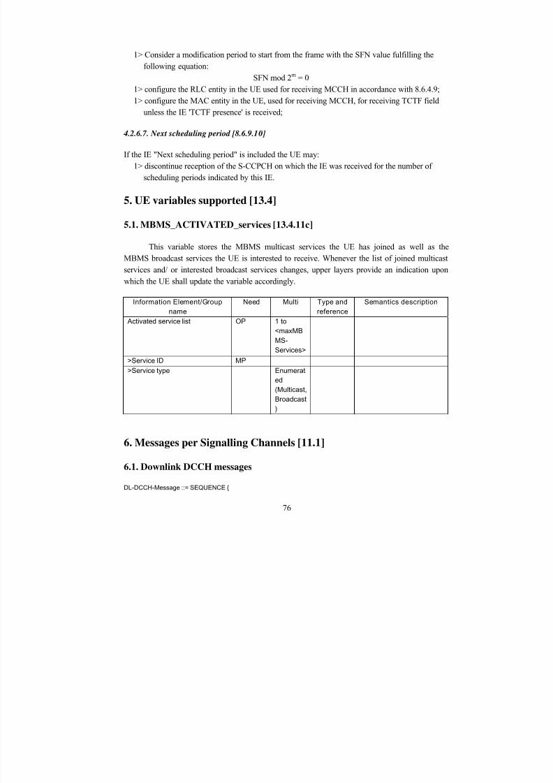
8/12/2019 Stage-nguyen Huu Nghia
http://slidepdf.com/reader/full/stage-nguyen-huu-nghia 76/90
1> Consider a modification period to start from the frame with the SFN value fulfilling thefollowing equation:
SFN mod 2m = 01> configure the RLC entity in the UE used for receiving MCCH in accordance with 8.6.4.9;1> configure the MAC entity in the UE, used for receiving MCCH, for receiving TCTF field
unless the IE 'TCTF presence' is received;
4.2.6.7. Next scheduling period [8.6.9.10]
If the IE "Next scheduling period" is included the UE may:1> discontinue reception of the S-CCPCH on which the IE was received for the number of
scheduling periods indicated by this IE.
5. UE variables supported [13.4]
5.1. MBMS_ACTIVATED_services [13.4.11c]
This variable stores the MBMS multicast services the UE has joined as well as theMBMS broadcast services the UE is interested to receive. Whenever the list of joined multicastservices and/ or interested broadcast services changes, upper layers provide an indication upon
which the UE shall update the variable accordingly.
Information Element/Group
name
Need Multi Type and
reference
Semantics description
Activated service list OP 1 to
<maxMB
MS-
Services>
>Service ID MP
>Service type Enumerat
ed
(Multicast,
Broadcast
)
6. Messages per Signalling Channels [11.1]
6.1. Downlink DCCH messages
DL-DCCH-Message ::= SEQUENCE {
76
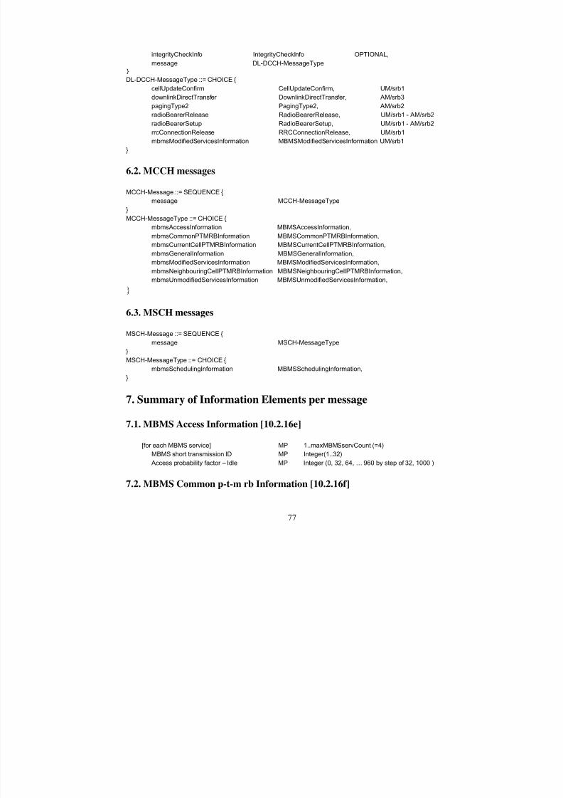
8/12/2019 Stage-nguyen Huu Nghia
http://slidepdf.com/reader/full/stage-nguyen-huu-nghia 77/90
integrityCheckInfo IntegrityCheckInfo OPTIONAL,
message DL-DCCH-MessageType
}
DL-DCCH-MessageType ::= CHOICE {
cellUpdateConfirm CellUpdateConfirm, UM/srb1
downlinkDirectTransfer DownlinkDirectTransfer, AM/srb3
pagingType2 PagingType2, AM/srb2radioBearerRelease RadioBearerRelease, UM/srb1 - AM/srb2
radioBearerSetup RadioBearerSetup, UM/srb1 - AM/srb2
rrcConnectionRelease RRCConnectionRelease, UM/srb1
mbmsModifiedServicesInformation MBMSModifiedServicesInformation UM/srb1
}
6.2. MCCH messages
MCCH-Message ::= SEQUENCE {
message MCCH-MessageType
}
MCCH-MessageType ::= CHOICE {
mbmsAccessInformation MBMSAccessInformation,
mbmsCommonPTMRBInformation MBMSCommonPTMRBInformation,
mbmsCurrentCellPTMRBInformation MBMSCurrentCellPTMRBInformation,
mbmsGeneralInformation MBMSGeneralInformation,
mbmsModifiedServicesInformation MBMSModifiedServicesInformation,
mbmsNeighbouringCellPTMRBInformation MBMSNeighbouringCellPTMRBInformation,
mbmsUnmodifiedServicesInformation MBMSUnmodifiedServicesInformation,
}
6.3. MSCH messages
MSCH-Message ::= SEQUENCE {
message MSCH-MessageType
}
MSCH-MessageType ::= CHOICE {
mbmsSchedulingInformation MBMSSchedulingInformation,
}
7. Summary of Information Elements per message
7.1. MBMS Access Information [10.2.16e]
[for each MBMS service] MP 1..maxMBMSservCount (=4)
MBMS short transmission ID MP Integer(1..32)
Access probability factor – Idle MP Integer (0, 32, 64, … 960 by step of 32, 1000 )
7.2. MBMS Common p-t-m rb Information [10.2.16f]
77
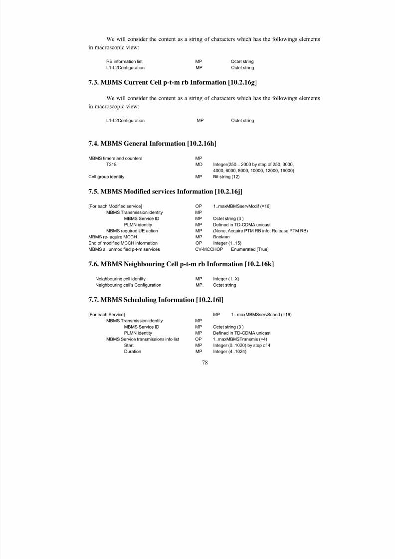
8/12/2019 Stage-nguyen Huu Nghia
http://slidepdf.com/reader/full/stage-nguyen-huu-nghia 78/90
We will consider the content as a string of characters which has the followings elements
in macroscopic view:
RB information list MP Octet string
L1-L2Configuration MP Octet string
7.3. MBMS Current Cell p-t-m rb Information [10.2.16g]
We will consider the content as a string of characters which has the followings elements
in macroscopic view:
L1-L2Configuration MP Octet string
7.4. MBMS General Information [10.2.16h]
MBMS timers and counters MP
T318 MD Integer(250... 2000 by step of 250, 3000,
4000, 6000, 8000, 10000, 12000, 16000)
Cell group identity MP Bit string (12)
7.5. MBMS Modified services Information [10.2.16j]
[For each Modified service] OP 1..maxMBMSservModif (=16)
MBMS Transmission identity MP
MBMS Service ID MP Octet string (3 )
PLMN identity MP Defined in TD-CDMA unicastMBMS required UE action MP (None, Acquire PTM RB info, Release PTM RB)
MBMS re- aquire MCCH MP Boolean
End of modified MCCH information OP Integer (1..15)
MBMS all unmodified p-t-m services CV-MCCHOP Enumerated (True)
7.6. MBMS Neighbouring Cell p-t-m rb Information [10.2.16k]
Neighbouring cell identity MP Integer (1..X)
Neighbouring cell’s Configuration MP. Octet string
7.7. MBMS Scheduling Information [10.2.16l]
[For each Service] MP 1.. maxMBMSservSched (=16)
MBMS Transmission identity MP
MBMS Service ID MP Octet string (3 )
PLMN identity MP Defined in TD-CDMA unicast
MBMS Service transmissions info list OP 1..maxMBMSTransmis (=4)
Start MP Integer (0..1020) by step of 4
Duration MP Integer (4..1024)
78

8/12/2019 Stage-nguyen Huu Nghia
http://slidepdf.com/reader/full/stage-nguyen-huu-nghia 79/90
Next scheduling period MP Integer (0..31)
7.8. MBMS Unmodified services Information [10.2.16m]
[For each unmodified service] OP 1..maxMBMSservUnmodif (=32)
MBMS Transmission identity MPMBMS Service ID MP Octet string (3 )
PLMN identity MP Defined in TD-CDMA unicast
MBMS required UE action MP Enumerated (None, Acquire PTM RB info, , Release
PTM RB)
79
8/12/2019 Stage-nguyen Huu Nghia
http://slidepdf.com/reader/full/stage-nguyen-huu-nghia 80/90
Annexe D – Document de conception (Anglais)
Design of RRC for MBMS
Working Document – Printed 06/12/2005
Michelle WETTERWALDHuu Nghia NGUYEN
Mobile Communication Department
Institut EurecomBP 193
F-06904 Sophia Antipolis Cedex - France
Tel: 04.93.00.26.31 - Fax: 04.93.00 26.27
Email : [email protected] [email protected]
web : http://www.eurecom..fr/Mobile
Annexe
D
80
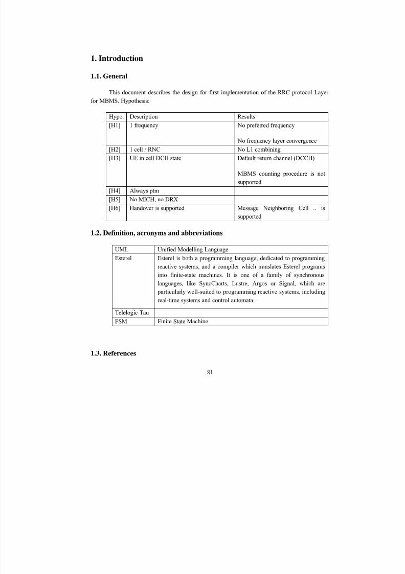
8/12/2019 Stage-nguyen Huu Nghia
http://slidepdf.com/reader/full/stage-nguyen-huu-nghia 81/90
1. Introduction
1.1. General
This document describes the design for first implementation of the RRC protocol Layer
for MBMS. Hypothesis:
Hypo. Description Results
[H1] 1 frequency No preferred frequency
No frequency layer convergence
[H2] 1 cell / RNC No L1 combining
[H3] UE in cell DCH state Default return channel (DCCH)
MBMS counting procedure is notsupported
[H4] Always ptm
[H5] No MICH, no DRX
[H6] Handover is supported Message Neighboring Cell .. issupported
1.2. Definition, acronyms and abbreviations
UML Unified Modelling Language
Esterel Esterel is both a programming language, dedicated to programmingreactive systems, and a compiler which translates Esterel programsinto finite-state machines. It is one of a family of synchronouslanguages, like SyncCharts, Lustre, Argos or Signal, which are particularly well-suited to programming reactive systems, includingreal-time systems and control automata.
Telelogic TauFSM Finite State Machine
1.3. References
81
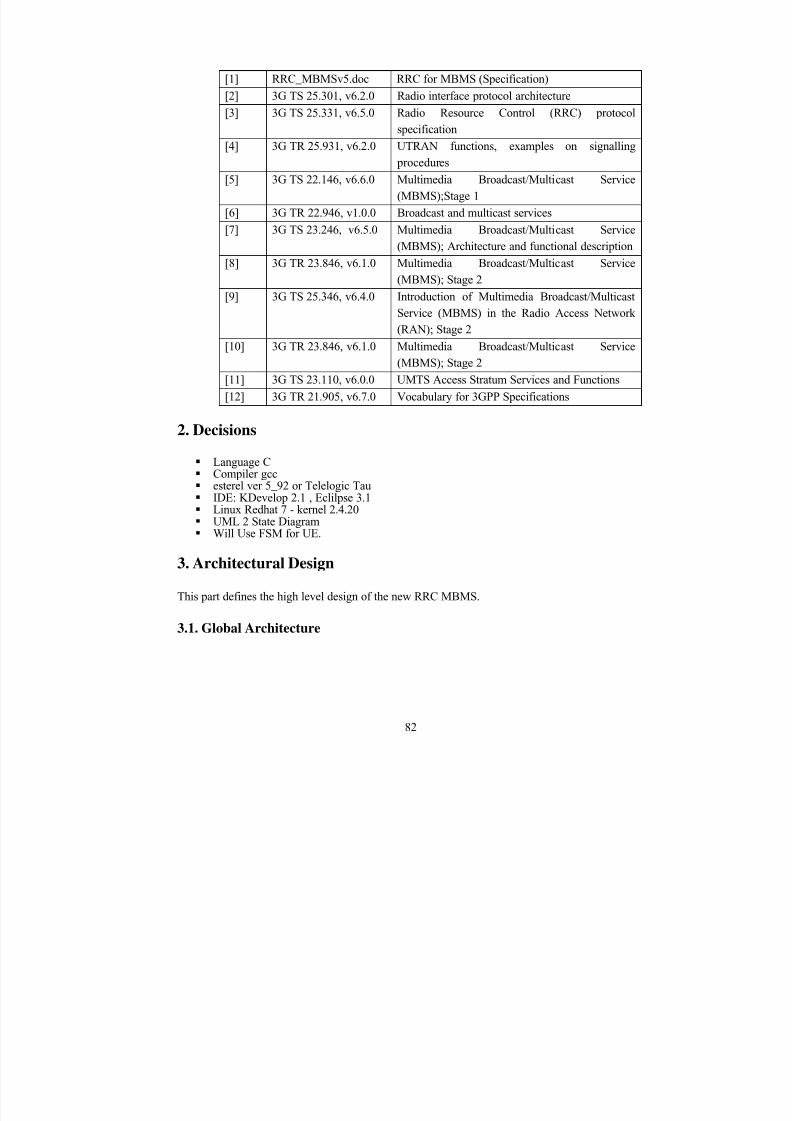
8/12/2019 Stage-nguyen Huu Nghia
http://slidepdf.com/reader/full/stage-nguyen-huu-nghia 82/90
[1] RRC_MBMSv5.doc RRC for MBMS (Specification)
[2] 3G TS 25.301, v6.2.0 Radio interface protocol architecture
[3] 3G TS 25.331, v6.5.0 Radio Resource Control (RRC) protocolspecification
[4] 3G TR 25.931, v6.2.0 UTRAN functions, examples on signalling procedures
[5] 3G TS 22.146, v6.6.0 Multimedia Broadcast/Multicast Service(MBMS);Stage 1
[6] 3G TR 22.946, v1.0.0 Broadcast and multicast services
[7] 3G TS 23.246, v6.5.0 Multimedia Broadcast/Multicast Service(MBMS); Architecture and functional description
[8] 3G TR 23.846, v6.1.0 Multimedia Broadcast/Multicast Service(MBMS); Stage 2
[9] 3G TS 25.346, v6.4.0 Introduction of Multimedia Broadcast/MulticastService (MBMS) in the Radio Access Network(RAN); Stage 2
[10] 3G TR 23.846, v6.1.0 Multimedia Broadcast/Multicast Service(MBMS); Stage 2
[11] 3G TS 23.110, v6.0.0 UMTS Access Stratum Services and Functions
[12] 3G TR 21.905, v6.7.0 Vocabulary for 3GPP Specifications
2. Decisions
Language C Compiler gcc esterel ver 5_92 or Telelogic Tau IDE: KDevelop 2.1 , Eclilpse 3.1 Linux Redhat 7 - kernel 2.4.20 UML 2 State Diagram Will Use FSM for UE.
3. Architectural Design
This part defines the high level design of the new RRC MBMS.
3.1. Global Architecture
82
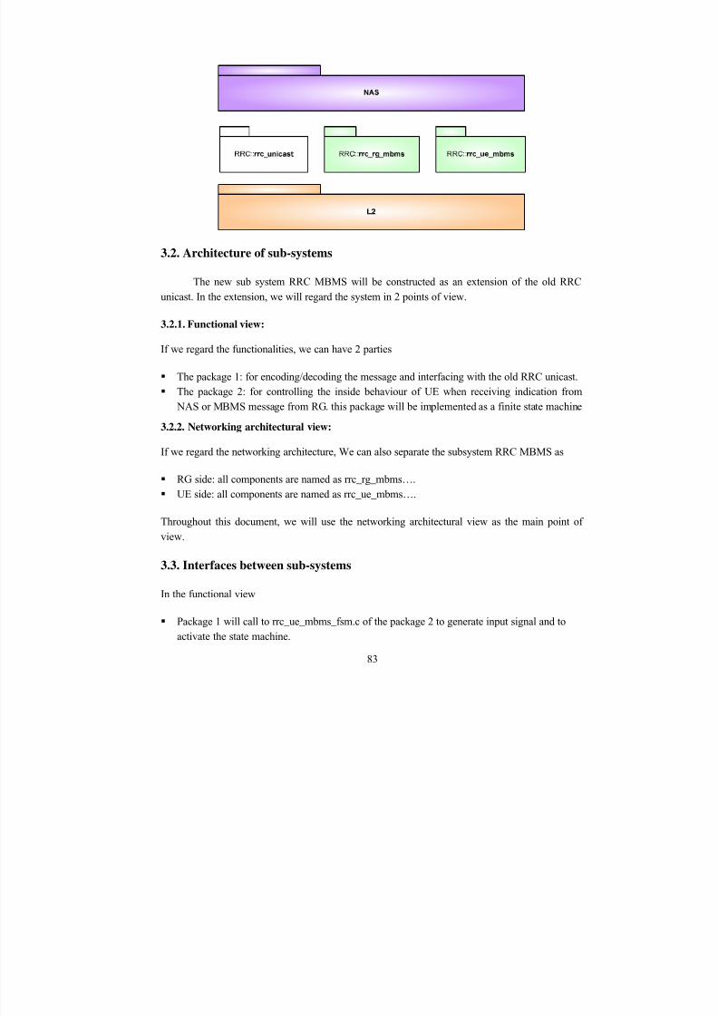
8/12/2019 Stage-nguyen Huu Nghia
http://slidepdf.com/reader/full/stage-nguyen-huu-nghia 83/90
3.2. Architecture of sub-systems
The new sub system RRC MBMS will be constructed as an extension of the old RRC
unicast. In the extension, we will regard the system in 2 points of view.
3.2.1. Functional view:
If we regard the functionalities, we can have 2 parties
The package 1: for encoding/decoding the message and interfacing with the old RRC unicast. The package 2: for controlling the inside behaviour of UE when receiving indication from
NAS or MBMS message from RG. this package will be implemented as a finite state machine3.2.2. Networking architectural view:
If we regard the networking architecture, We can also separate the subsystem RRC MBMS as
RG side: all components are named as rrc_rg_mbms…. UE side: all components are named as rrc_ue_mbms….
Throughout this document, we will use the networking architectural view as the main point of
view.
3.3. Interfaces between sub-systems
In the functional view
Package 1 will call to rrc_ue_mbms_fsm.c of the package 2 to generate input signal and toactivate the state machine.
83
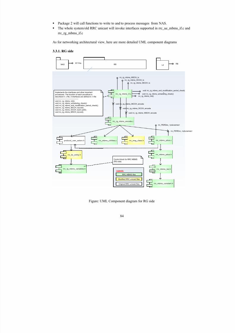
8/12/2019 Stage-nguyen Huu Nghia
http://slidepdf.com/reader/full/stage-nguyen-huu-nghia 84/90
Package 2 will call functions to write to and to process messages from NAS. The whole system/old RRC unicast will invoke interfaces supported in rrc_ue_mbms_if.c and
rrc_rg_mbms_if.c
As for networking architectural view, here are more detailed UML component diagrams
3.3.1. RG side
rrc_msg_class.h
rrc_mbms_ies.h
rrc_mbms_constant.h
rrc_mbms_pdus.c
rrc_PEREnc_<pdunames>
rrc_rg_mbms_init()
rrc_mbms_pdus.h
void rrc_rg_mbms_scheduling_check()rrc_rg_mbms_if.cImplements the interfaces and other important
procedures. The function of each procedure is
described in .c file, 3 interfaces are defined in .h file
--------------------------------------
void rrc_rg_mbms_init();
void rrc_rg_mbms_scheduling_check();
void rrc_rg_mbms_end_modification_period_check();
void rrc_rg_mbms_MCCH_tx(void);
void rrc_rg_mbms_DCCH_tx(int ueID);
void rrc_rg_mbms_MSCH_tx(void);
rrc_rg_mbms_encode.c
protocol_vars_extern.h rrc_mbms_utilities.c
void rrc_rg_mbms_MCCH_encode
void rrc_rg_mbms_DCCH_encode
void rrc_rg_mbms_MSCH_encode
rrc_bs_entity.h
rrc_rg_mbms_variables.h
rrc_PERDec_<pdunames>
RBRT FifoL2NAS RR
RRC MBMS files
Original RRC unicast files
Modified RRC unicast files
rrc_rg_mbms_MSCH_tx
rrc_rg_mbms_DCCH_tx
rrc_rg_mbms_MCCH_tx
void rrc_rg_mbms_end_modification_period_check()
Legends:
Control block for RRC MBMS
(RG side)
Figure: UML Component diagram for RG side
84
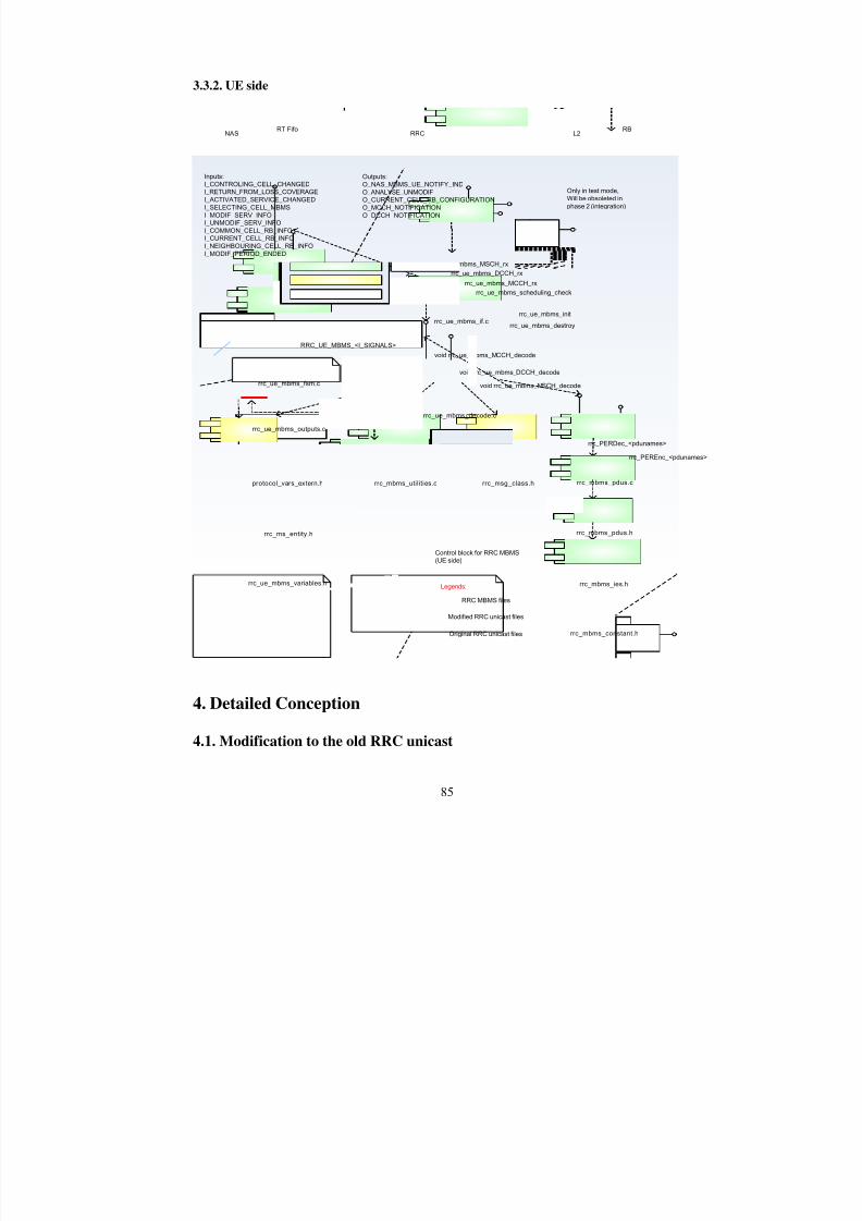
8/12/2019 Stage-nguyen Huu Nghia
http://slidepdf.com/reader/full/stage-nguyen-huu-nghia 85/90
3.3.2. UE side
rrc_msg_class.h
rrc_mbms_ies.h
rrc_mbms_constant.h
rrc_mbms_pdus.c
rrc_PEREnc_<pdunames>
rrc_PERDec_<pdunames>
rrc_mbms_pdus.h
protocol_vars_extern.h rrc_mbms_utilities.c
void rrc_ue_mbms_MCCH_decode
void rrc_ue_mbms_DCCH_decode
void rrc_ue_mbms_MSCH_decode
rrc_ms_entity.h
rrc_ue_mbms_variables.h
rrc_ue_mbms_if.c
rrc_ue_mbms_decode.c
rrc_ue_mbms_scheduling_check
rrc_ue_mbms_init
rrc_ue_mbms_destroy
rrc_ue_mbms_fsm.c
rrc_ue_mbms_outputs.c
rrc_ue_mbms_fsm
Inputs:
I_CONTROLING_CELL_CHANGEDI_RETURN_FROM_LOSS_COVERAGE
I_ACTIVATED_SERVICE_CHANGED
I_SELECTING_CELL_MBMS
I_MODIF_SERV_INFOI_UNMODIF_SERV_INFO
I_COMMON_CELL_RB_INFOI_CURRENT_CELL_RB_INFO
I_NEIGHBOURING_CELL_RB_INFO
I_MODIF_PERIOD_ENDED
Outputs:
O_NAS_MBMS_UE_NOTIFY_IND
O_ANALYSE_UNMODIFO_CURRENT_CELL_RB_CONFIGURATION
O_MCCH_NOTIFICATION
O_DCCH_NOTIFICATION
RRC_UE_MBMS_<I_SIGNALS>
rrc_ue_mbms_MCCH_rx
rrc_ue_mbms_DCCH_rx
rrc_ue_mbms_MSCH_rx
Only in test mode,
Will be obsoleted in
phase 2 (integration)
RBRT FifoL2NAS RRC
RRC MBMS files
Original RRC unicast files
Modified RRC unicast files
Legends:
Control block for RRC MBMS(UE side)
4. Detailed Conception
4.1. Modification to the old RRC unicast
85
8/12/2019 Stage-nguyen Huu Nghia
http://slidepdf.com/reader/full/stage-nguyen-huu-nghia 86/90
We will try to keep it as much stable as possible. It means that we avoid modifying the
existing source code of RRC unicast. Modification is realised in 3 files:
rrc_msg_class.h: Addition of types: MCCHMessage, MSCHMessage, …. rrc_ms_entity: Addition of an mbms control block for UE rrc_bs_entity: Addition of an mbms control block for RG
4.2. Encode, Decode and Interface
4.2.1. Description
For this part, we will use the ASN.1 for constant, variables, timers, pdus, messages specifiedin the [TS 25.331#11].
To encode and decode, we need to define a control block for UE side and RG side. Here arenecessary information (macroscopic view):
4.2.1.1. UE MBMS control block
Attribute Source
T318 Default ms1000, MBMS General Information
CellGroupIdentity MBMS General Information
unmodifiedServices[] MBMS Unmodified Services Information
modifiedServices[] MBMS Modified Services Information
L1L2Config Common/Current MBMS RB Information
RBInformationList[] Common MBMS RB Information
reacquireMCCH MBMS Modified Services Information
accessInfoPeriodCoefficient MBMS-MCCH-ConfigurationInfo-r6 (SIB5)
repetitionPeriodCoefficient MBMS-MCCH-ConfigurationInfo-r6 (SIB5)
modificationPeriodCoefficient MBMS-MCCH-ConfigurationInfo-r6 (SIB5)
neigbouringCellInfoList[] Neigboring Cell RB Information
Scheduling (later)
For more details, view the definition in rrc-ue-mbms-variables.h
4.2.1.2. RG MBMS control block
Attribute Source
T318 Default ms1000
CellGroupIdentity NAS/protocol_bs
unmodifiedServices[] NAS primitives
modifiedServices[] NAS primitives
86
8/12/2019 Stage-nguyen Huu Nghia
http://slidepdf.com/reader/full/stage-nguyen-huu-nghia 87/90
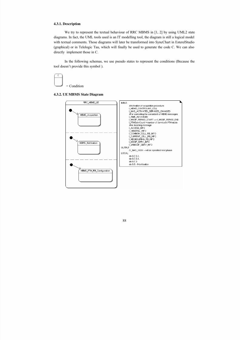
8/12/2019 Stage-nguyen Huu Nghia
http://slidepdf.com/reader/full/stage-nguyen-huu-nghia 88/90
4.3.1. Description
We try to represent the textual behaviour of RRC MBMS in [1, 2] by using UML2 statediagrams. In fact, the UML tools used is an IT modelling tool, the diagram is still a logical modelwith textual comments. Those diagrams will later be transformed into SyncChart in EsterelStudio
(graphical) or in Telelogic Tau, which will finally be used to generate the code C. We can alsodirectly implement those in C.
In the following schemas, we use pseudo states to represent the conditions (Because thetool doesn’t provide this symbol ).
= Condition
4.3.2. UE MBMS State Diagram
88
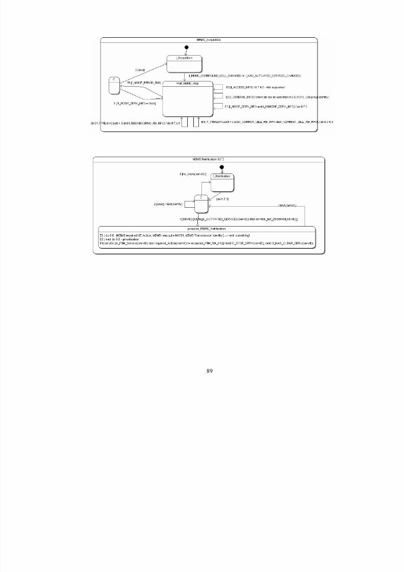
8/12/2019 Stage-nguyen Huu Nghia
http://slidepdf.com/reader/full/stage-nguyen-huu-nghia 89/90
89
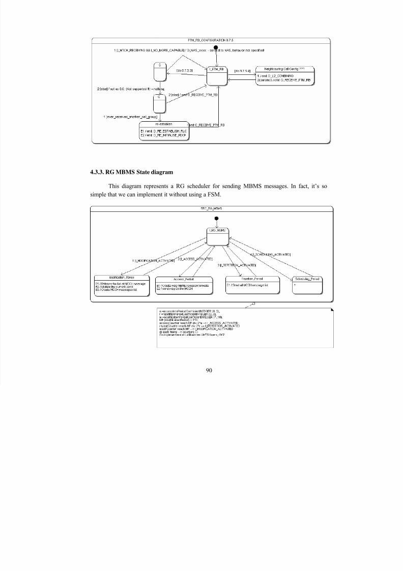
8/12/2019 Stage-nguyen Huu Nghia
http://slidepdf.com/reader/full/stage-nguyen-huu-nghia 90/90
4.3.3. RG MBMS State diagram
This diagram represents a RG scheduler for sending MBMS messages. In fact, it’s sosimple that we can implement it without using a FSM.


![UY . HOA xX CHi] NGHiA VIET. NAM TiNH THAI NGUYEN](https://img.pdfslide.net/doc/110x75/61982ca294ad713061341be3/uy-hoa-xx-chi-nghia-viet-nam-tinh-thai-nguyen.jpg)