Embed Size (px)
Citation preview
International Business Network
WEB: www.ibn.lt
E-mail: [email protected]
StairDesigner VI
Stair Design to Measure
User Manual - Version 6
StairDesigner Std / Pro / Pro_DXF / Pro_RB

P 2

P 3
StairDesigner VI
TABLE OF CO%TE%TS
I. I%TRODUCTIO%
I. 1 Presentation : 4
I. 2 Installation : 6
I. 3 StairDesigner Windows : 7
II. WI%DI%G PRI%CIPLES
II. 1 Integral Winding : 8
II. 2 Winding Coefficients : 10
II. 3 Specific Winding Situations : 13
III. STAIR RULE
III. 1 Blondel Rule : 14
III. 2 Control Function : 14
III. 3 Help Function : 15
IV. STAIRWELL
IV. 1 Multi-Flight Stairwell Parameters : 16
IV. 2 Joins between Successive Flights : 18
IV. 3 Headroom Control : 20
IV. 4 Intermediate Landings : 21
IV. 5 Flights with Non-Parallel Sides : 23
V. STEPS A%D RISERS
V. 1 Step Categories : 24
V. 2 Step and Riser Parameters : 26
V. 3 Step Shaping : 28
P 4
TABLE OF CO%TE%TS
(Continued)
VI. STRI%GBOARDS
VI. 1 Stringboard Parameters : 30
VI. 2 Various Stringboard Shapes : 31
VII. CUT STRI%GS A%D SOFFITS
VII. 1 The three Cut String Types : 32
VII. 2 Soffits : 33
VII. 3 Central Cut Strings : 34
VII. 4 Lateral Cut Strings : 35
VIII. %EWEL POSTS
VIII. 1 The three Newel Post Types : 36
VIII. 2 Newel Post Parameters : 37
IX. HA%DRAILS A%D BA%ISTERS
IX. 1 Handrail Parameters : 38
IX. 2 Banister Parameters : 39
IX. 3 Banister Machining and Distribution : 40
X. CO%CRETE STAIR COVERAGE : 41
X. 1 Input of the Existing Concrete Stair : 42
X. 2 Parameters and Optimization : 44
XI. RESULT PRI%TOUTS
XI. 1 Project Mode Printout : 47
XI. 2 Template Mode Printout : 52
XI. 3 Data Lists : 54
XII. DXF EXPORTS : 55
P 5
StairDesigner VI
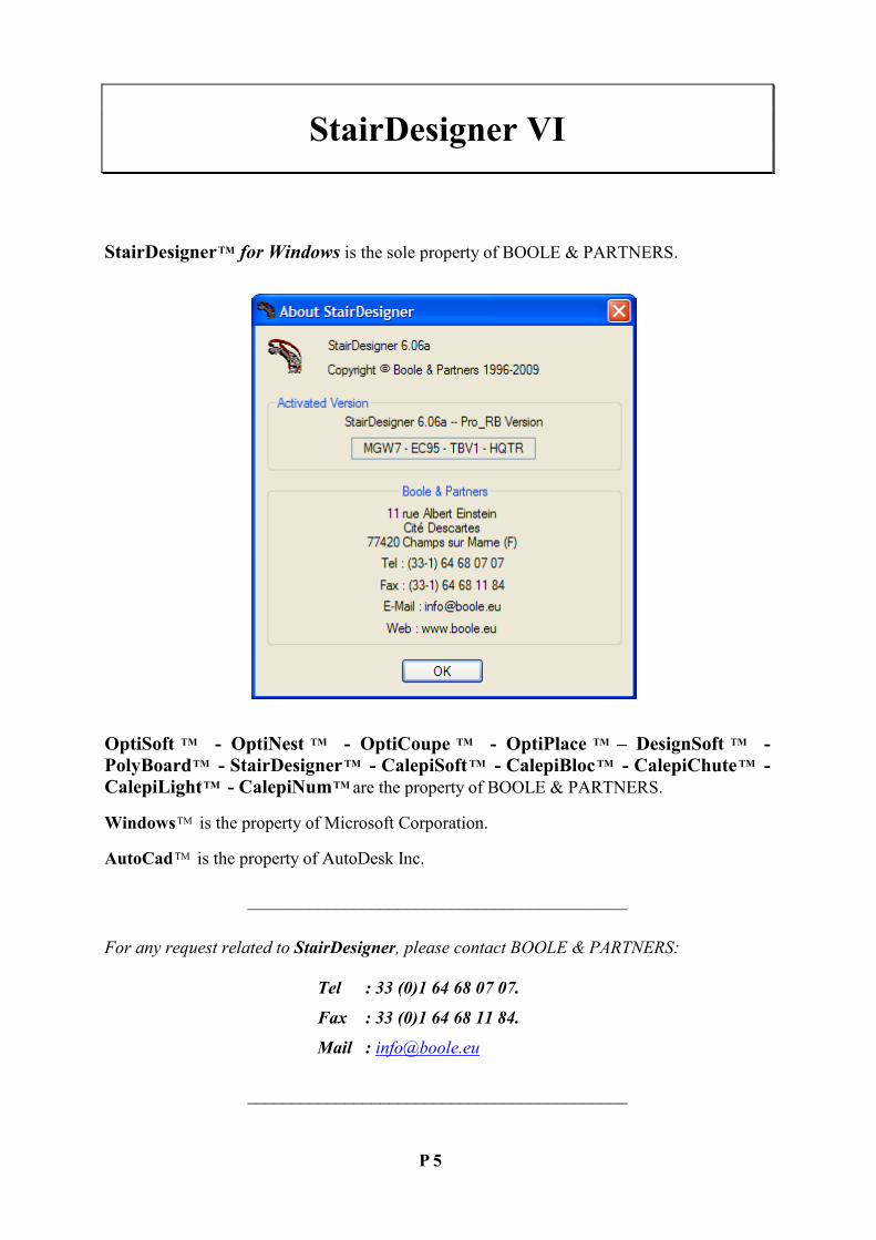
StairDesigner TM for Windows is the sole property of BOOLE & PARTNERS.
OptiSoft TM - Opti%est TM - OptiCoupe TM - OptiPlace TM – DesignSoft TM -
PolyBoard TM - StairDesigner TM - CalepiSoft TM - CalepiBloc TM - CalepiChute TM -
CalepiLight TM - Calepi%um TM are the property of BOOLE & PARTNERS.
Windows TM is the property of Microsoft Corporation.
AutoCad TM is the property of AutoDesk Inc.
___________________________________________
For any request related to StairDesigner, please contact BOOLE & PART�ERS:
Tel : 33 (0)1 64 68 07 07.
Fax : 33 (0)1 64 68 11 84.
Mail : [email protected]
___________________________________________

P 6
I. I%TRODUCTIO%
Preface
Stair design has no other limit but the architect's and stairmaker's creativity as they compete in
order to give their stairs the architectural position that we owe them. We actually use them so
often that we sometimes forget they are there.
Whether they are made of wood, metal, stone or mixed materials (metal and wood, stone and
glass), all stairs follow the same common design rules but their variety of shape is unlimited.
This is why no single software would be able to cover all the stair shapes and styles.
However, it can analyse every aspect of a stair up to fabrication details or give at least the
foundation of the more complex ones.
Stair examples
I. 1 PRESE%TATIO%
StairDesigner VI is a software that helps designing stairs to measure. It was developed by
BOOLE & PARTNERS, editor for professional software since 1988, whose product range
benefits of the experience of thousands of licences used in more than 30 countries.
StairDesigner VI is available in the following 4 versions:
- StairDesigner VI-Std : Standard version, limited to printouts in A4 format.
- StairDesigner VI-Pro : Prints out templates on a scale of 1:1.
- StairDesigner VI-Pro_DXF : Prints out 2D and 3D DXF files.
- StairDesigner VI-Pro_RB : Optimizes concrete stair coverage.

P 7
I. 2 I%STALLATIO%
StairDesigner VI can be installed on every personal computer that runs with Windows
(Windows 98 / 2000 / XP Pro / Vista). You can install it with the file
"InstallStairDesigner.exe" that is available on CD or the website www.boole.eu.
When you execute the file "InstallStairDesigner.exe" the following window opens:
Now just follow the instructions: the installation only takes a few seconds.
Once StairDesigner VI is installed, you may execute it via the shortcut on your desktop.
Clicking on the "Demo version" button allows you to use StairDesigner VI in its demo mode
until you enter the Activation Code we will provide you.
To receive the Activation Code, you have to send us your user code per E-mail or Fax.
________________________
@ IMPORTA%T:
You should absolutely uninstall StairDesigner VI before altering your hard drive.
To do this, open the menu "Start / Programs" of your computer and execute the command
"Boole & Partners / StairDesigner 6 / Uninstall StairDesigner".
ATTE%TIO%: Do not forget to write down the code provided during the uninstallation.
________________________

P 8
I. 3 STAIRDESIG%ER WI%DOWS
StairDesigner VI has a 2D working window that displays different elements of the stair
during its creation (plan view, stringboards, steps, newel posts, cut strings, etc.) and a 3D
displaying window. The symbol "3D/ 2D" switches between the two.
StairDesigner 2D window
StairDesigner 3D window
P 9
II. WI%DI%G PRI%CIPLES
The winding of a stair is the rule that places every step and influences every fabrication detail.
The aesthetics and comfort of a stair depend on the quality of its winding.
A well wound stair looks harmonious and is comfortable to climb.
One may consider that a stair is well wound if the climbing movement is similar to the
climbing movement of a straight stair.
StairDesigner VI uses the general winding function of BOOLE & PARTNERS that results
from more than fifteen years of experience in winding calculation techniques.
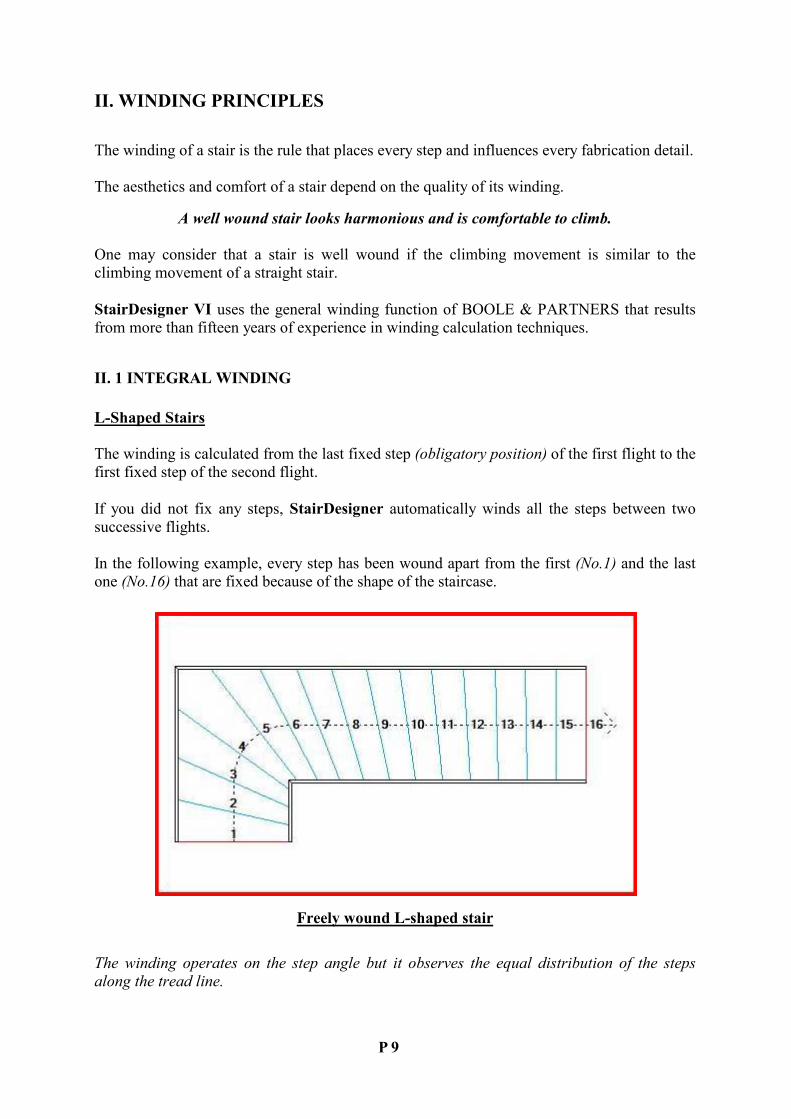
II. 1 I%TEGRAL WI%DI%G
L-Shaped Stairs
The winding is calculated from the last fixed step (obligatory position) of the first flight to the
first fixed step of the second flight.
If you did not fix any steps, StairDesigner automatically winds all the steps between two
successive flights.
In the following example, every step has been wound apart from the first (�o.1) and the last
one (�o.16) that are fixed because of the shape of the staircase.
Freely wound L-shaped stair
The winding operates on the step angle but it observes the equal distribution of the steps
along the tread line.

P 10
U- or S-Shaped Stairs
When the stair contains more than two flights (3 or more), StairDesigner inserts a virtual
step in every intermediate flight so as to create a sequence of calculations between two
successive flights.
In the following example, a virtual step was inserted between steps No.8 and No.9 (pictured
in red) and two winding calculations succeed each other and merge in order to guarantee the
harmonious shape of the stair.
U-shaped stair: 2 successive windings with a virtual step
When you fix one or more steps in an intermediate flight, StairDesigner deletes the virtual
step and the winding is based on the fixed steps (which is the case of step �o.8 in the
following example).
S-shaped stair: 2 successive windings with a fixed step
P 11
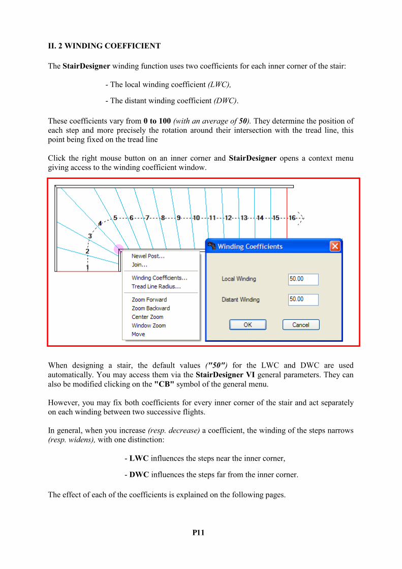
II. 2 WI%DI%G COEFFICIE%T
The StairDesigner winding function uses two coefficients for each inner corner of the stair:
- The local winding coefficient (LWC),
- The distant winding coefficient (DWC).
These coefficients vary from 0 to 100 (with an average of 50). They determine the position of
each step and more precisely the rotation around their intersection with the tread line, this
point being fixed on the tread line
Click the right mouse button on an inner corner and StairDesigner opens a context menu
giving access to the winding coefficient window.
When designing a stair, the default values ("50") for the LWC and DWC are used
automatically. You may access them via the StairDesigner VI general parameters. They can
also be modified clicking on the "CB" symbol of the general menu.
However, you may fix both coefficients for every inner corner of the stair and act separately
on each winding between two successive flights.
In general, when you increase (resp. decrease) a coefficient, the winding of the steps narrows
(resp. widens), with one distinction:
- LWC influences the steps near the inner corner,
- DWC influences the steps far from the inner corner.
The effect of each of the coefficients is explained on the following pages.

P 12
Local Winding Coefficient
When the local winding coefficient of an inner corner increases, the winding of the steps
narrows around this inner corner, with an impact on all the steps in the winding zone.
However, the effect of the LWC diminishes the further the steps are away from the inner
corner.
LWC = 50 LWC = 75 LWC = 100
In the above example, the winding was successively calculated with three different values
LWC = 50, 75, and 100 (maintaining the DWC at 50).
From 75 to 100, the steps around the inner corner are still slightly narrowing, whereas those
far from the inner corner cannot straighten themselves up any more.
Distant Winding Coefficient
An increase of the distant winding coefficient makes the steps far from the inner corner
straighten up which has an impact on all the steps in the winding zone.
Contrary to the LWC, the effect of the DWC diminishes the nearer the steps are to the inner
corner.
Left: effect of the local coefficient – Right: effect of the distant coefficient
P 13
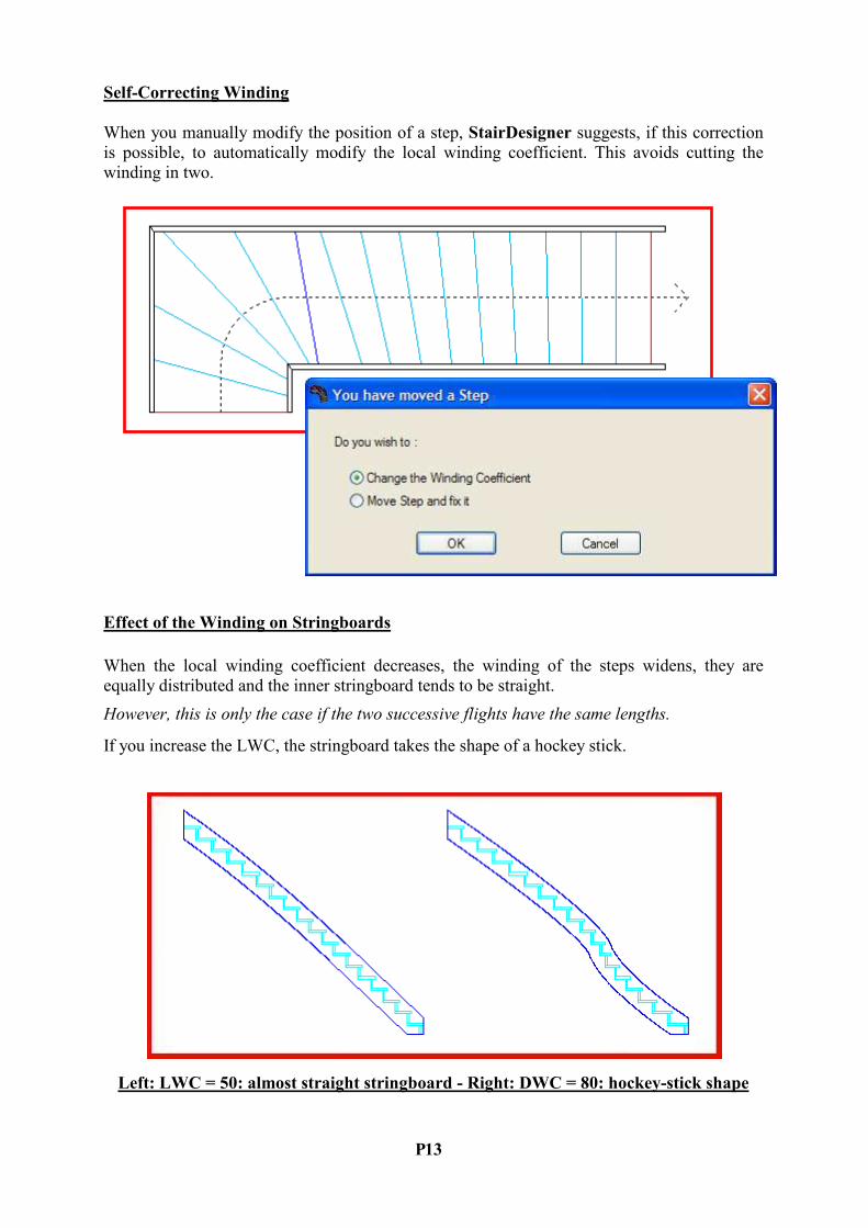
Self-Correcting Winding
When you manually modify the position of a step, StairDesigner suggests, if this correction
is possible, to automatically modify the local winding coefficient. This avoids cutting the
winding in two.
Effect of the Winding on Stringboards
When the local winding coefficient decreases, the winding of the steps widens, they are
equally distributed and the inner stringboard tends to be straight.
However, this is only the case if the two successive flights have the same lengths.
If you increase the LWC, the stringboard takes the shape of a hockey stick.
Left: LWC = 50: almost straight stringboard - Right: DWC = 80: hockey-stick shape

P 14
II. 3 SPECIFIC WI%DI%G SITUATIO%S
Equal Winding
If a winding zone between two fixed steps does not have an inner corner; StairDesigner
equally distributes the steps between the two edges of the stair.
In the example above, two steps (�o.3 and �o.10) have been fixed. Thus, there are three
winding zones: steps 1 to 3 and 10 to 16 are equally distributed.
Centred Winding
When the well hole of a stair is quite narrow, the standard winding function leads to a radial
pattern that is often thought to be less harmonious.
For this reason, StairDesigner offers an optional mode called "centred winding".
Left: winding with radial pattern - Right: centred winding

P 15
III. STAIR RULE
III. 1 BLO%DEL RULE
Nicolas-François Blondel (1618-1686) was the first architect to study the relation between the
height of a step and its tread width.
He found that the length of a comfortable step on an even surface is the double of the step
height on a vertical ladder. He concluded that two times the step height plus the tread width
correspond to the length of a step.
The length of a comfortable step is about 62 cm. The Blondel Rule, also called Stair Rule,
says:
60 < (2xH + T) < 64
Due to recent increases in the size of the human body those values may be replaced by 62 and
66.
III. 2 CO%TROL FU%CTIO%
In addition to the Blondel Rule, the control function avoids the stair being:
- Too steep, which leaves too little space for the feet on the steps and
would make it difficult to climb, or
- Too shallow, which would take up too much space.
The parameters "height" and "tread width" are controlled by means of a maximum and
a minimum value so that the inclination of the stair remains at 33° ± 5°.
StairDesigner offers a control function for the three parameters of the tread line (you can see
whether the stair observes these three parameters thanks to the red or green point on the OK
button of the window "stairwell parameters").
P 16
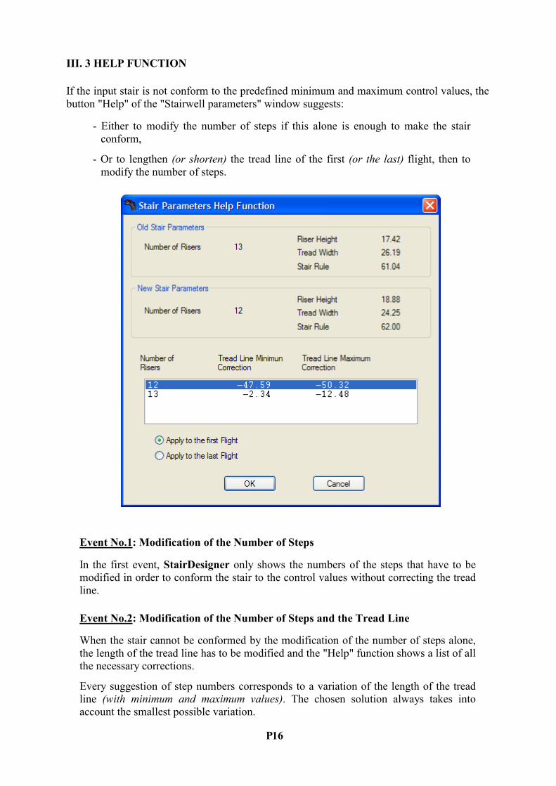
III. 3 HELP FU%CTIO%
If the input stair is not conform to the predefined minimum and maximum control values, the
button "Help" of the "Stairwell parameters" window suggests:
- Either to modify the number of steps if this alone is enough to make the stair
conform,
- Or to lengthen (or shorten) the tread line of the first (or the last) flight, then to
modify the number of steps.
Event %o.1: Modification of the %umber of Steps
In the first event, StairDesigner only shows the numbers of the steps that have to be
modified in order to conform the stair to the control values without correcting the tread
line.
Event %o.2: Modification of the %umber of Steps and the Tread Line
When the stair cannot be conformed by the modification of the number of steps alone,
the length of the tread line has to be modified and the "Help" function shows a list of all
the necessary corrections.
Every suggestion of step numbers corresponds to a variation of the length of the tread
line (with minimum and maximum values). The chosen solution always takes into
account the smallest possible variation.

P 17
IV. STAIRWELL
A stairwell corresponds to the space a stair takes up. It is defined by its:
- Plan view,
- Total height, or floor height,
- Total number of steps and
- If necessary, the position of intermediate landings as well as
the distribution of the steps between these landings.
It is convenient to indicate whether the thickness of the stringboards is or is not included in
the stairwell (stringboard in stairwell / off stairwell).
Be sure not to mix up the stairwell with the well hole that corresponds to the hole made in the
ceiling of the upper floor.
IV. 1 MULTI-FLIGHT STAIRWELL PARAMETERS
The window below shows how to input a stair with several flights.
Every flight is defined by its length along its reference side (left or right), its width and its
angle with the previous flight. You can add a new flight using the button "Add flight" until a
maximum of 7 flights.

P 18
Stairwell with Parallel Sides
By default, StairDesigner displays the reduced window above with one angle between two
successive flights, corresponding to a stairwell with parallel sides.
A click on the ">>" button shows the advanced window below with two further columns that
differentiate left and right angles.
You can input stairwells with non-parallel sides using the advanced window (see end of the
chapter).
When the case "Left rotation" is ticked, this flight will turn to the left whereas the default
rotation is to the right.
The start angle (resp. end angle) is the angle of the first (resp. the last) step to its own flight
(the value "0" corresponds to a step that is perpendicular to the flight).
Place the cursor on the line of the flight you want to delete and click on the button "Delete
flight" (by default, the last flight is deleted).
The button "Reset" resets the winding of the stair (by re-establishing the tread line and the
winding coefficients by default) and deletes all the newel posts.
The length of the landing step is deduced from the length of the last flight.
When the option "Stringboard in stairwell" is ticked, the thickness of the stringboards is
deduced from the dimensions of the stairwell.
The main stringboard parameters, e.g. their thickness, are directly accessible through the button "Stringboard parameters".
In the current version, the number of flights is limited to 7 (there are 4 in the example above).
Those flights must not overlap each other in the plan view.

P 19
IV. 2 JOI%S BETWEE% SUCCESSIVE FLIGHTS
Right-click on the inner corner between two successive flights to:
- Create a newel post in which both stringboards will end, or
- Create a join with an arc or a cut-off.
Choose the option "Join" in the context menu above to open the following window. It varies
depending on the options "Arc" or "Cut-off":
If you choose an arc, the parameter "Radius" defines the radius of the arc created between two
flights.
If you choose a "Cut-off", the two parameters "Bottom recess" and "Top recess" define the
positions of its ends depending on the original intersection.
The following parameters define the kind of stringboard and handrail (curved or straight), and
whether there are banisters in the join.

P 20
Joins with an Arc
The following example shows two joins with an arc. The inner one has a radius of 200 mm,
the outer one of 500 mm.
The stringboard with a circular join corresponds to the join and two curved stringboards.
Because of its twisted shape, it cannot be cut flatly.
Joins with a Cut-Off
The following example shows a join with a cut-off of 300 mm x 300 mm.
There cannot be a newel post where there is a join with a cut-off.

P 21
IV. 3 HEADROOM CO%TROL
Using the headroom control, you can check if there is enough space over the steps so that the
head does not hit the ceiling.
The "Headroom control" function allows you to define the dimensions of the well hole from
the last step, its alignment and the floor thickness.
By clicking the button "Parameters" you can define the minimum passage height, as well as
the level of tolerance that allows a part of the step to not observe the height limit.
The "Control" section shows the guaranteed passage height with the given tolerance.
In the above example, the minimum passage height is 2 metres (2000 mm) and the tolerance
level is 10%.
The first winding (upper stair) guarantees a passage height of 1975 mm, marked in red in the
"Control" section because it does not observe the desired minimum height.
In the second winding (lower stair), the local winding coefficient has been increased and step
No.3 inclined so that 90% of the nosing is under the well hole.
The passage height increases by one step height from 1975 mm to 2150 mm, now exceeding
the minimum height of 2000 mm.

P 22
IV. 4 I%TERMEDIATE LA%DI%GS
Where there are no intermediate landings, all the steps are equally distributed along the tread
line so as to guarantee a constant tread width.
Double-click on the context menu below to create an intermediate landing limited by the
selected step and the following one.
The "Intermediate landing" function allows you to insert an intermediate landing at any point
of the stair. It divides into two or more interlandings, each with their own height and tread
width.
The two successive steps that limit an intermediate landing can be moved freely, either by
clicking on the function "Move step" or by double-clicking on the step itself. This opens the
following window in which you can determine the position of the step:

P 23
Step Height and Tread Width of Interlandings
The command "Landing parameters" of the "Parameter" menu shows the number of steps,
their height and tread width as well as the tread line for every interlanding (the non-conform
values are marked in red).
You may define the number of steps separately for each interlanding and the option "Set all
step heights equal" adjusts the heights of all landings.
A stair can have one or more intermediate landings, either between two successive flights or
along one flight.
In the example above (two views), you can see a stair with two intermediate landings. The
first one is between flight No.2 and No.3, the second one along the third flight.

P 24
IV. 5 FLIGHTS WITH %O%-PARALLEL SIDES
With StairDesigner you can create flights with non-parallel sides.
You can input this kind of stair by differentiating the left and right angles between two
successive flights in the advanced window.
In the example below, the first flight has a vertical right side and a left side that is inclined to
the right by 5°.
Likewise, the right side of the second flight is perpendicular to the right side of the first one,
whereas its left side is at a 100° angle to the previous side (and thus, it is inclined by 5°
upwards compared to the horizontal).
Both left and right sides of the third flight are perpendicular to the corresponding sides of the
second one and maintain an angle of 5° between them.
This kind of construction allows for example to fix cut strings on the walls of a room that is
not right-angled, however maintaining perpendicular inner stringboards.
This makes the fabrication and assembly of wooden stairs easier.

P 25
V. STEPS A%D RISERS
V. 1 STEP CATEGORIES
In StairDesigner, a step(*) can have 4 different categories, marked by 4 colours:
- Wound : light blue
- Floating : orange
- Fixed : red
- Landing : green
(*): In StairDesigner, step means the line along the nosing.
A wound step belongs to the winding zone between two fixed steps and its position is
defined by the winding coefficients.
The rotation of a wound step either corrects the local winding coefficient or fixes the step.
In both cases, the positions of the other steps are automatically corrected.
When a wound step becomes fix, the winding zone to which it belongs is cut in two.
A floating step also belongs to a winding zone but it can rotate freely around the tread line
without influencing the other steps.
A fixed step separates two winding zones.
A straight step is a fixed step whose predefined position is perpendicular to the tread line (it
is either perpendicular to the flight or to the arc).
A landing step forms an intermediate landing with a second adjacent step.
These categories are accessible through the context menu you can see by right-clicking on the
step.
When you select a step in order to modify it, its colour becomes dark blue no matter its
category.
Direct Modification of a Step Category
A step category can be modified with its context menu (see below). This has different
consequences on the position of the steps.
Fixing an originally wound step for example, modifies the winding of the steps below and
beyond.
However, transforming a wound step into a floating or landing step does not influence the
position of the other steps but can affect later modifications.

P 26
Modification of a Step Category after a Rotation
In order to rotate a step you can either double-click on it and then fix the angle in one of the
two "Angle" boxes or execute the command "Move step" of the context menu and then rotate
the step manually around the tread line with the help of the mouse.
After the rotation of the step by one of the two methods above, the self-correcting winding
function analyses if the step can be maintained as a wound step by modifying the local
winding coefficient.
If it is impossible to maintain the step category "wound", its category will be modified to
"fixed".
P 27
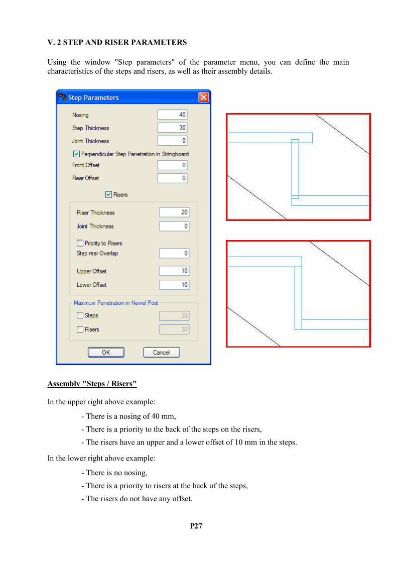
V. 2 STEP A%D RISER PARAMETERS
Using the window "Step parameters" of the parameter menu, you can define the main
characteristics of the steps and risers, as well as their assembly details.
Assembly "Steps / Risers"
In the upper right above example:
- There is a nosing of 40 mm,
- There is a priority to the back of the steps on the risers,
- The risers have an upper and a lower offset of 10 mm in the steps.
In the lower right above example:
- There is no nosing,
- There is a priority to risers at the back of the steps,
- The risers do not have any offset.

P 28
Perpendicular Penetration in the Stringboard
The penetration of the steps in the stringboard allows, when there is no offset, not to increase
the cutting dimensions and to machine the stringboard perpendicularly to its front.
Step Offset
Both parameters "Front offset" and "Rear offset" define the offsets on the sides of the steps
that penetrate the stringboard (pictured in grey below).
Step and Riser Joints
These joints allow some space between the steps and risers and their cut string. They are
mainly used for the mortar in marble stairs.
P 29
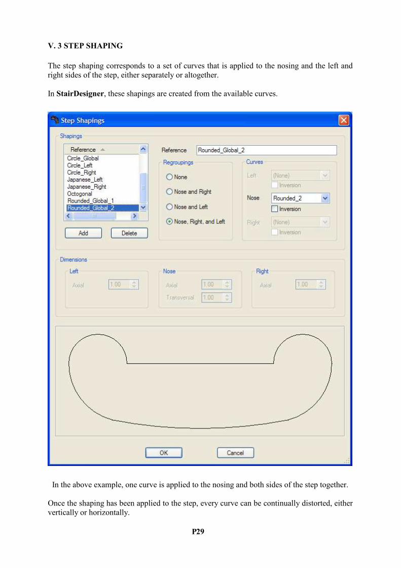
V. 3 STEP SHAPI%G
The step shaping corresponds to a set of curves that is applied to the nosing and the left and
right sides of the step, either separately or altogether.
In StairDesigner, these shapings are created from the available curves.
In the above example, one curve is applied to the nosing and both sides of the step together.
Once the shaping has been applied to the step, every curve can be continually distorted, either
vertically or horizontally.

P 30
Shaping Curves
The curves used for the shaping are originally polylines in DXF format that have been drawn
in a CAD software, then imported in StairDesigner.
Using the window "Curves" of the parameter menu, you can manage the curve list, import
new ones and delete existing curves as long as they are not used by an existent shaping.
The below left example shows a curve that has been applied to the nosing and both sides
together, whereas the below right example shows a curve that has been applied to the nosing
alone.
In the example on the right, the horizontal distortion of the shaping allows the design of
alternating tread stairs.
P 31
VI. STRI%GBOARDS
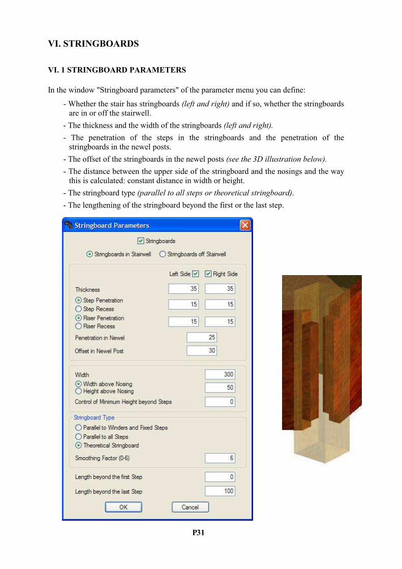
VI. 1 STRI%GBOARD PARAMETERS
In the window "Stringboard parameters" of the parameter menu you can define:
- Whether the stair has stringboards (left and right) and if so, whether the stringboards
are in or off the stairwell.
- The thickness and the width of the stringboards (left and right).
- The penetration of the steps in the stringboards and the penetration of the
stringboards in the newel posts.
- The offset of the stringboards in the newel posts (see the 3D illustration below).
- The distance between the upper side of the stringboard and the nosings and the way
this is calculated: constant distance in width or height.
- The stringboard type (parallel to all steps or theoretical stringboard).
- The lengthening of the stringboard beyond the first or the last step.
P 32
VI. 2 VARIOUS STRI%GBOARD SHAPES
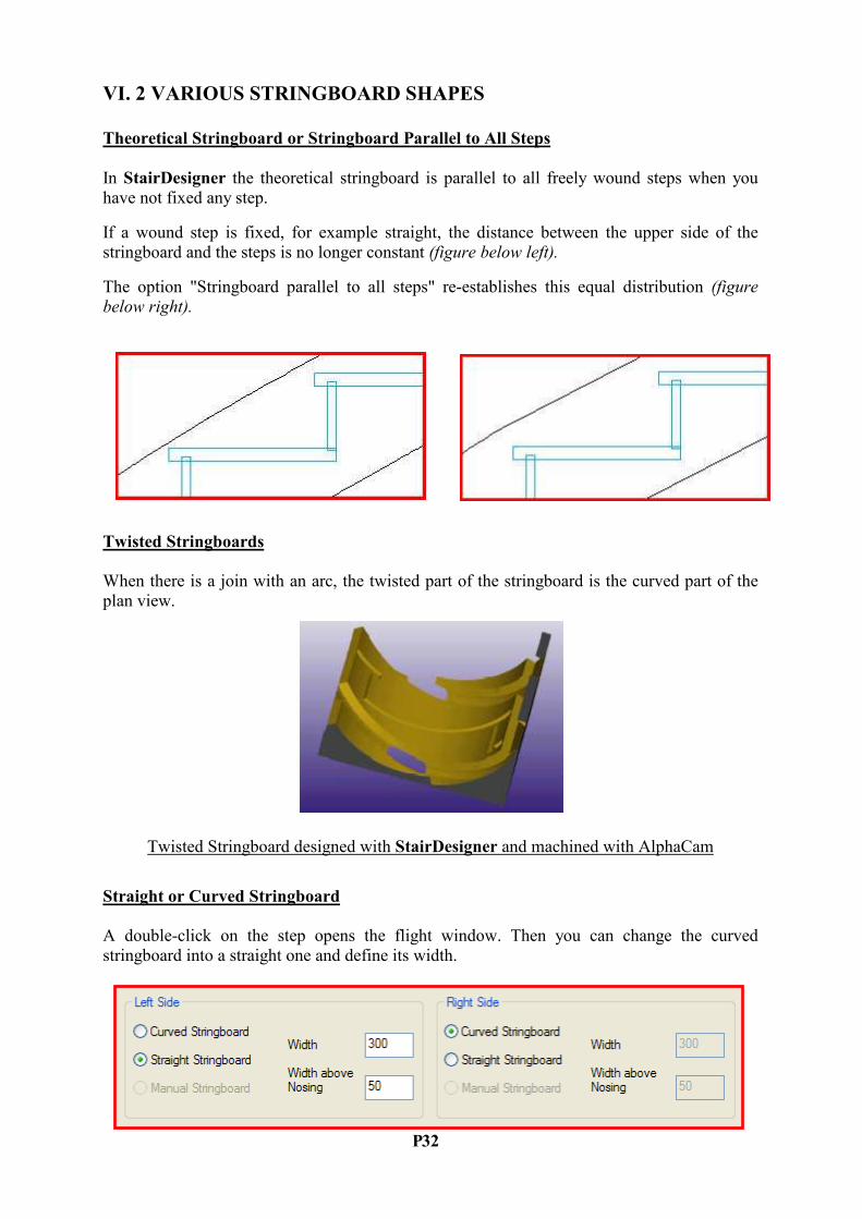
Theoretical Stringboard or Stringboard Parallel to All Steps
In StairDesigner the theoretical stringboard is parallel to all freely wound steps when you
have not fixed any step.
If a wound step is fixed, for example straight, the distance between the upper side of the
stringboard and the steps is no longer constant (figure below left).
The option "Stringboard parallel to all steps" re-establishes this equal distribution (figure
below right).
Twisted Stringboards
When there is a join with an arc, the twisted part of the stringboard is the curved part of the
plan view.
Twisted Stringboard designed with StairDesigner and machined with AlphaCam
Straight or Curved Stringboard
A double-click on the step opens the flight window. Then you can change the curved
stringboard into a straight one and define its width.

P 33
VII. CUT STRI%GS A%D SOFFITS
VII. 1 THE THREE CUT STRI%G TYPES
Cut strings are the elements under the steps that take their jagged form and support them.
There are three types of cut strings:
- Soffits that are generally made of concrete and cover the whole width of the stair,
- Central cut strings that are close to the tread line and
- Lateral cut strings (left and right) that are generally fixed on the wall.
The window "Cut string parameters" of the parameter menu shows these three types.
According to the type, you can choose their width, thickness and offset:
Central Cut Strings
The central cut string consists of a lower part with a smooth surface and an upper part where
the steps are fixed.
In StairDesigner, the lower part is called "Central cut string".

P 34
VII. 2 SOFFITS
The soffit of a stair is a cut string defined by the total width of the stair.
When the soffit is covered by steps and risers it can have a lateral recess compared to the
steps:
The stair may also consist of the sole soffit:
Soffit and Winding
The winding of a stair takes into account the visible steps.
In the case of a covered stair, the winding thus takes into account the covered steps and not
the steps of the soffit. The latter is defined by the winding plus a recess.
Vice versa, when a wound soffit is covered, the finished stair does no longer observe the
winding rules (see chapter "Concrete Stair Coverage").

P 35
VII. 3 CE%TRAL CUT STRI%GS
When the option "Central cut string" in the "Cut string parameters" window is ticked, the
following list appears so you can choose between three types of cut strings:
The constant width cut string (below left) is generally used in wooden constructions, whereas
the spreadable bottom cut string (middle) or the boxed stringboard (right) are used in metal
constructions.
The main advantage of the boxed stringboard is that its sides have a constant width whereas
the sides of the spreadable bottom cut string are irregular.
However, the first two central cut strings can be incongruent with the tread line while the
boxed stringboard must be the same as the tread line because the development of its sides is
only approximate.
The above figure shows the three parts of the underside of a boxed cut string (left) and the
underside of a spreadable bottom cut string (right).

P 36
VII. 4 LATERAL CUT STRI%GS
Lateral cut strings are an alternative for stringboards. They support the steps and risers that
directly rest on the cut strings.
The indentation is bevelled so as to fit the form of the wound steps.
Both lateral cut strings of an L-shaped stair
When a cut string is fixed on the wall it ends at the same point as the steps (below left). When
it is fixed otherwise there can be a lateral offset (right).
Lateral cut string outside Lateral cut string inside

P 37
VIII. %EWEL POSTS
VIII. 1 THE THREE %EWEL POST TYPES
In StairDesigner there are three types of newel posts: extremity newel posts, corner newel
posts and intermediate newel posts (along one flight).
You can create a newel post by right-clicking on the pink zones on the extremities and corners
(for the first two types) or between the steps (for the third one).
The inner corner newel post of the figure above is illustrated in 3D below left (semi-
transparent) and its four developed sides in the middle.
When the angle between two flights is not 90°, the offset parameters can create a six-sided
newel post (above right) in order to avoid creating a fragile diamond-shaped newel post.

P 38
VIII. 2 %EWEL POST PARAMETERS
When you create a newel post, a parameter window opens according to the type of newel post
you have chosen.
Once you have created the newel post, double-click in plan view to modify or delete it.
The section of the newel post is determined by its left and right offset and the thickness of the
stringboard if there is one.
The height of the newel post results from the height of its base and its top that are defined
separately.
The corner newel post can have one or two offsets (see page 35).
The position of the start (resp. end) newel post can be defined by the extremity of the
stringboard or by the position of the first (resp. last) step.

P 39
IX. HA%DRAILS A%D BA%ISTERS
IX. 1 HA%DRAIL PARAMETERS
In the current version of StairDesigner, handrails have a rectangular section so as to easily
define the machining of its lower side that holds the banisters.
You can specify the handrail parameters in the following window:
From side view, the handrails can be curved or straight independently from the stringboards,
but in plan view, they follow the join (arc or cut-off) of the stair:
P 40
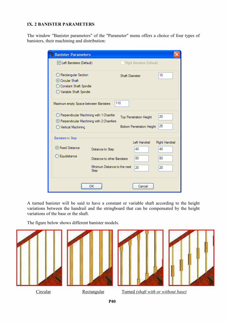
IX. 2 BA%ISTER PARAMETERS
The window "Banister parameters" of the "Parameter" menu offers a choice of four types of
banisters, their machining and distribution:
A turned banister will be said to have a constant or variable shaft according to the height
variations between the handrail and the stringboard that can be compensated by the height
variations of the base or the shaft.
The figure below shows different banister models.
Circular Rectangular Turned (shaft with or without base)
P 41
IX. 3 BA%ISTER MACHI%I%G A%D DISTRIBUTIO%
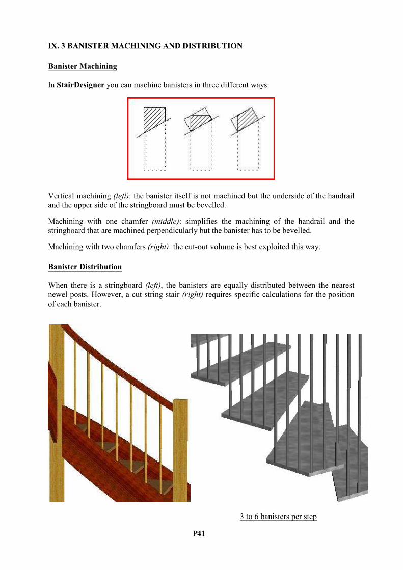
Banister Machining
In StairDesigner you can machine banisters in three different ways:
Vertical machining (left): the banister itself is not machined but the underside of the handrail
and the upper side of the stringboard must be bevelled.
Machining with one chamfer (middle): simplifies the machining of the handrail and the
stringboard that are machined perpendicularly but the banister has to be bevelled.
Machining with two chamfers (right): the cut-out volume is best exploited this way.
Banister Distribution
When there is a stringboard (left), the banisters are equally distributed between the nearest
newel posts. However, a cut string stair (right) requires specific calculations for the position
of each banister.
3 to 6 banisters per step
P 42
X. CO%CRETE STAIR COVERAGE
Preface
When an already cast concrete stair is to be covered in wood, marble or stone, the concrete
has often to be transformed in order to obtain a harmonious result:
- Either because the steps of the existing concrete stair are irregular and thus do
not observe the general winding rules,
- Or because the original winding of the concrete stair did not take into account
the changes due to the coverage, as for example the thickness of the risers and
joints or the nosings.
One thus has to "load" and "break" the existing concrete.
Please note that it is generally easier to load than to break.
An ideal solution with minimum effort may be obtained by optimizing the winding and
according to the case, by moving the tread line, lengthening the first flight, changing the start
and end angles or combining these modifications.
Finding such a solution is a demanding and time-consuming task for stairmakers.
__________________
StairDesigner VI-Pro_RB offers specific functions for the calculation and optimization of
concrete stair coverage.
From the input of a concrete stair, StairDesigner uses a reversed calculation method to find
the most convenient finished stair, taking into account your parameters.
StairDesigner tests a high number of wound stairs and calculates the transformation cost of
the loaded and broken concrete surface for each of it.
The search of a solution follows two successive steps:
1 – Input of the existing concrete stair
- Input of the existing concrete stairwell
- Input of the step dimensions
2 – Parameters and optimization
- Parameters of the finished stair
- Optimization parameters
- Execution of the optimization
After its calculations, StairDesigner automatically finds an optimized solution that you can
change manually. Afterwards you can see the effect of this change on the final result in regard
to the surface that has to be loaded or broken.
P 43
X. 1 I%PUT OF THE EXISTI%G CO%CRETE STAIR
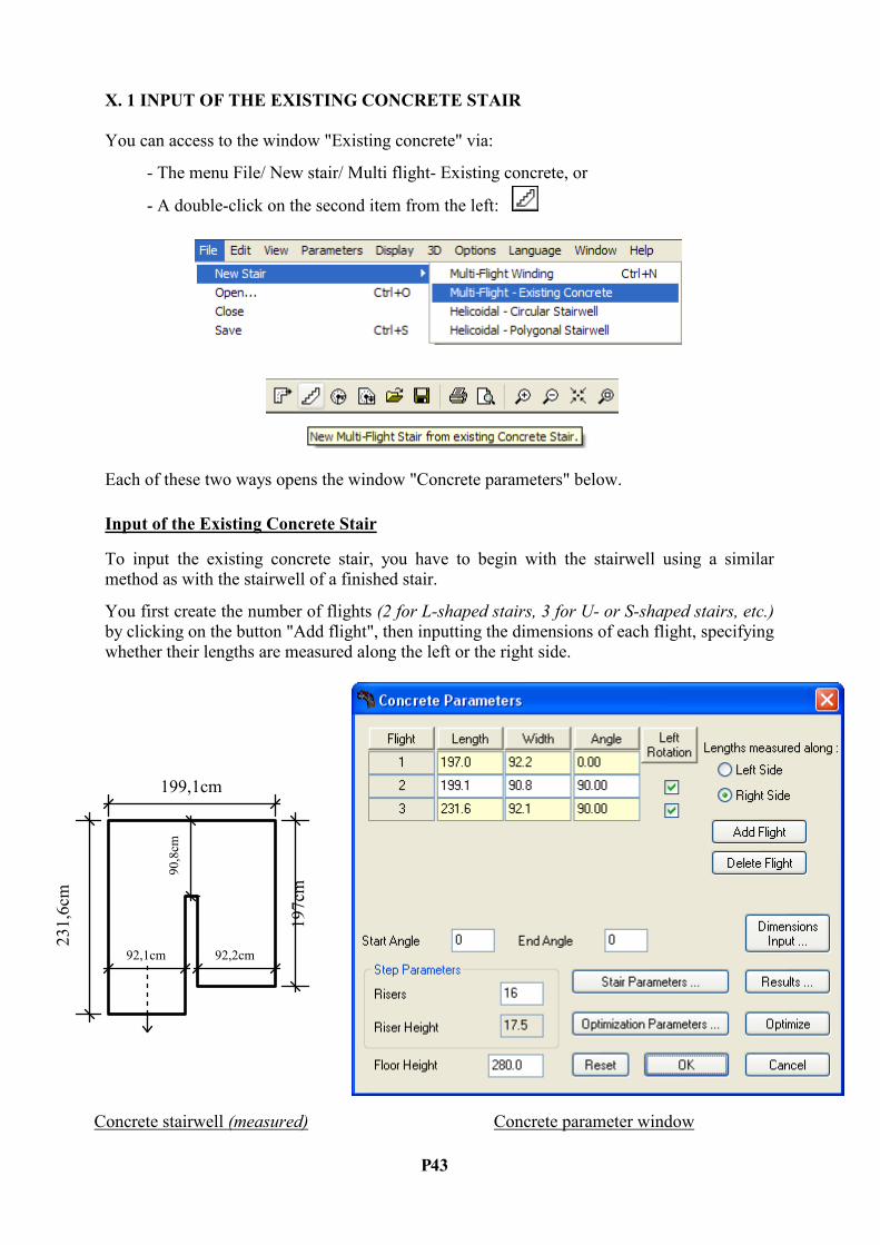
You can access to the window "Existing concrete" via:
- The menu File/ New stair/ Multi flight- Existing concrete, or
- A double-click on the second item from the left:
Each of these two ways opens the window "Concrete parameters" below.
Input of the Existing Concrete Stair
To input the existing concrete stair, you have to begin with the stairwell using a similar
method as with the stairwell of a finished stair.
You first create the number of flights (2 for L-shaped stairs, 3 for U- or S-shaped stairs, etc.)
by clicking on the button "Add flight", then inputting the dimensions of each flight, specifying
whether their lengths are measured along the left or the right side.
199,1cm
197cm
231,6cm
92,2cm
90,8cm
92,1cm
Concrete stairwell (measured) Concrete parameter window
P 44
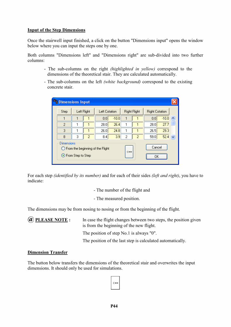
Input of the Step Dimensions
Once the stairwell input finished, a click on the button "Dimensions input" opens the window
below where you can input the steps one by one.
Both columns "Dimensions left" and "Dimensions right" are sub-divided into two further
columns:
- The sub-columns on the right (highlighted in yellow) correspond to the
dimensions of the theoretical stair. They are calculated automatically.
- The sub-columns on the left (white background) correspond to the existing
concrete stair.
For each step (identified by its number) and for each of their sides (left and right), you have to
indicate:
- The number of the flight and
- The measured position.
The dimensions may be from nosing to nosing or from the beginning of the flight.
@ PLEASE %OTE : In case the flight changes between two steps, the position given
is from the beginning of the new flight.
The position of step No.1 is always "0".
The position of the last step is calculated automatically.
Dimension Transfer
The button below transfers the dimensions of the theoretical stair and overwrites the input
dimensions. It should only be used for simulations.
P 45
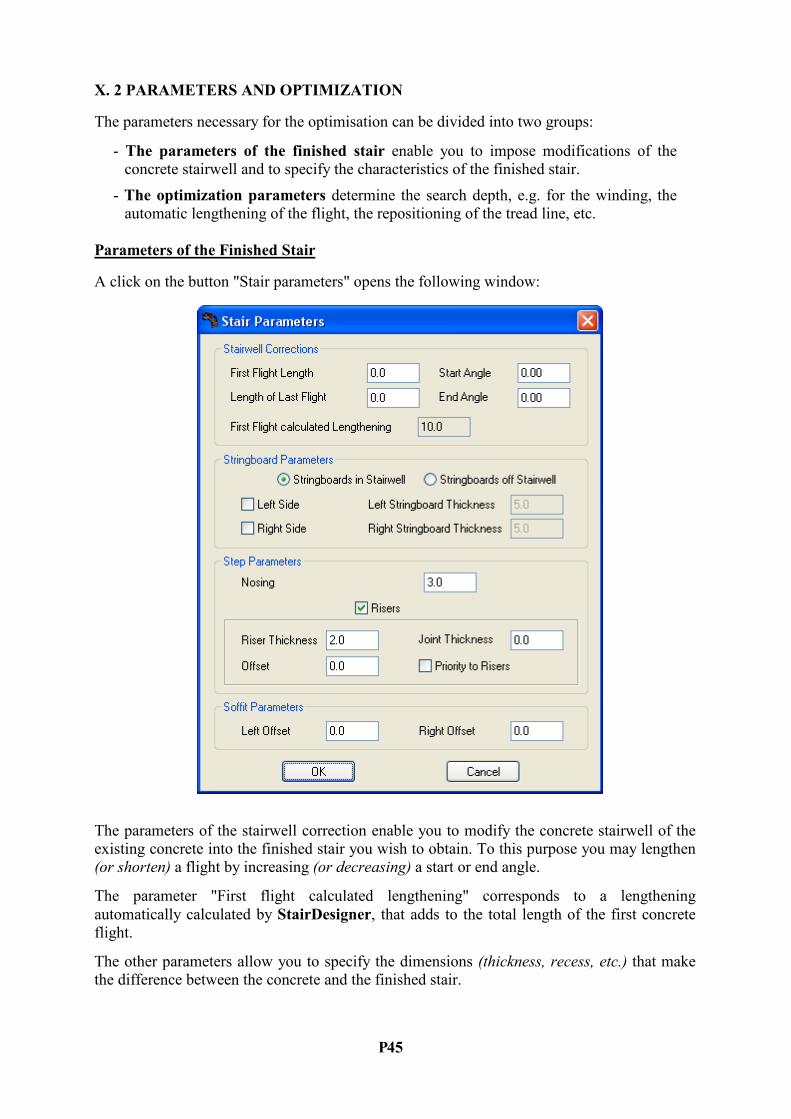
X. 2 PARAMETERS A%D OPTIMIZATIO%
The parameters necessary for the optimisation can be divided into two groups:
- The parameters of the finished stair enable you to impose modifications of the
concrete stairwell and to specify the characteristics of the finished stair.
- The optimization parameters determine the search depth, e.g. for the winding, the
automatic lengthening of the flight, the repositioning of the tread line, etc.
Parameters of the Finished Stair
A click on the button "Stair parameters" opens the following window:
The parameters of the stairwell correction enable you to modify the concrete stairwell of the
existing concrete into the finished stair you wish to obtain. To this purpose you may lengthen
(or shorten) a flight by increasing (or decreasing) a start or end angle.
The parameter "First flight calculated lengthening" corresponds to a lengthening
automatically calculated by StairDesigner, that adds to the total length of the first concrete
flight.
The other parameters allow you to specify the dimensions (thickness, recess, etc.) that make
the difference between the concrete and the finished stair.
P 46
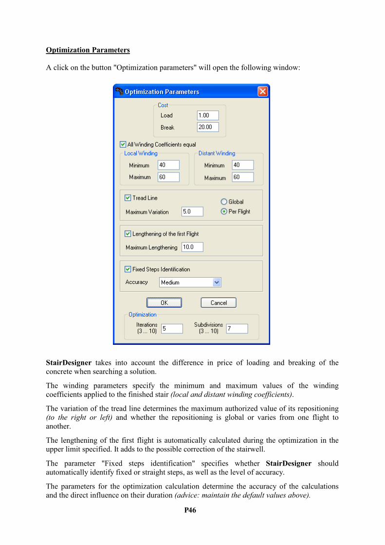
Optimization Parameters
A click on the button "Optimization parameters" will open the following window:
StairDesigner takes into account the difference in price of loading and breaking of the
concrete when searching a solution.
The winding parameters specify the minimum and maximum values of the winding
coefficients applied to the finished stair (local and distant winding coefficients).
The variation of the tread line determines the maximum authorized value of its repositioning
(to the right or left) and whether the repositioning is global or varies from one flight to
another.
The lengthening of the first flight is automatically calculated during the optimization in the
upper limit specified. It adds to the possible correction of the stairwell.
The parameter "Fixed steps identification" specifies whether StairDesigner should
automatically identify fixed or straight steps, as well as the level of accuracy.
The parameters for the optimization calculation determine the accuracy of the calculations
and the direct influence on their duration (advice: maintain the default values above).

P 47
Optimization Results
Once the input finished, you just have to click on the button "Optimize" in the "Concrete
parameter" window to launch the search for a solution.
The duration of the calculations depend on the number of flights and the optimization
parameters. It can vary from several seconds to several minutes.
When the calculations are finished, the following result window (left) opens automatically
and shows you the results.
When you close the windows, the screen shows the finished stair and its soffit (in green), as
well as the measured concrete (in red) so that you can see the existing and the finished stair at
the same time.
Using the parameter "Concrete correction" in the folder printing options, you can print out the
above document that specifies from step to step how the concrete must be corrected.
On the basis of this first automatic result, you can freely change the results and see the impact
by re-opening the result window.
P 48
XI. RESULT PRI%TOUTS
StairDesigner can print out the results in two modes:
- The "Project" mode for small-scale printouts,
- The "Template" mode for 1:1 printouts.
XI. 1 PROJECT MODE PRI%TOUT
In the project mode you can print a 3D view of the stair, a 2D view of each of its elements, the
cutting list and the summary.
In the "Standard" version, only the "automatic scale" is available.
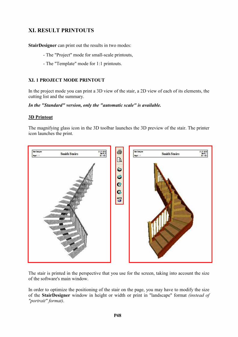
3D Printout
The magnifying glass icon in the 3D toolbar launches the 3D preview of the stair. The printer
icon launches the print.
The stair is printed in the perspective that you use for the screen, taking into account the size
of the software's main window.
In order to optimize the positioning of the stair on the page, you may have to modify the size
of the StairDesigner window in height or width or print in "landscape" format (instead of
"portrait" format).

P 49
2D-Project Printout and Summaries
The command "Project printing options" of the "File" menu opens the window below where
you can select the elements you want to print as well as their composition:
2D plan view

P 50
Step Printout
StairDesigner prints a scheme of the step and gives its cutting, main dimensions and the
characteristics of the riser below.
Stringboard Printout
StairDesigner shows the cutting of the stringboard, its main dimensions and the position of
the steps and risers that fit into it.
When the stringboards penetrate the newel post, the position of the newel post and the offset
of the stringboard are shown as well.

P 51
Newel Post Printout
StairDesigner shows the positions of the steps, the risers and the handrail.
Handrail and Banister Printouts
StairDesigner prints the developed handrail with its newel posts and banisters as well as the
details concerning every individual banister.
P 52
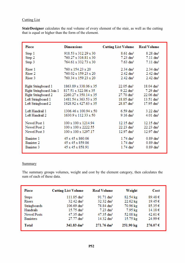
Cutting List
StairDesigner calculates the real volume of every element of the stair, as well as the cutting
that is equal or higher than the form of the element.
Summary
The summary groups volumes, weight and cost by the element category, then calculates the
sum of each of these data.

P 53
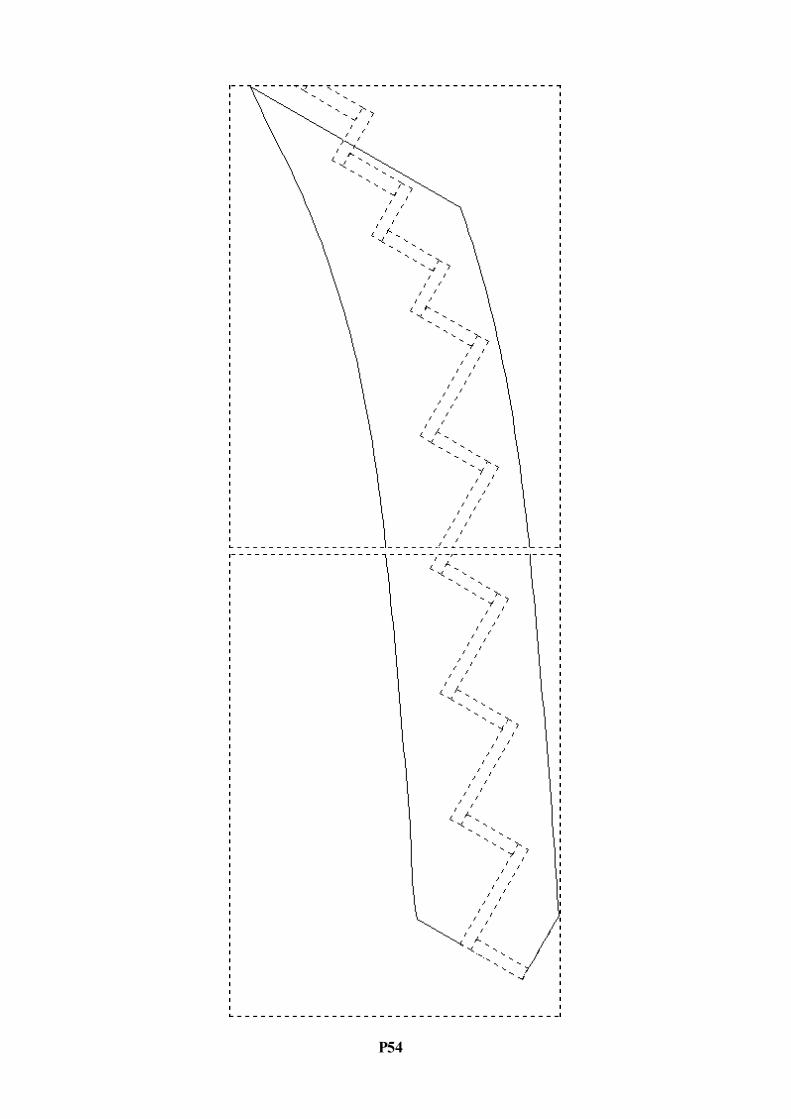
XI. 2 TEMPLATE MODE PRI%TOUT
In the template mode you can print the plan view of the stair and its elements in a scale of 1:1,
adjusting to your printer or plotter.
The option "Optimized angle" orients the object so as to reduce the length of the printed paper
P 54
P 55
XI. 3 DATA LISTS
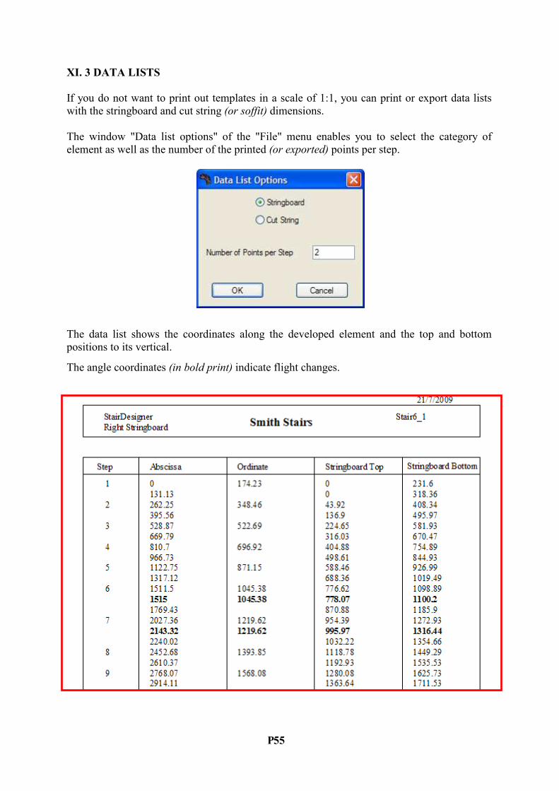
If you do not want to print out templates in a scale of 1:1, you can print or export data lists
with the stringboard and cut string (or soffit) dimensions.
The window "Data list options" of the "File" menu enables you to select the category of
element as well as the number of the printed (or exported) points per step.
The data list shows the coordinates along the developed element and the top and bottom
positions to its vertical.
The angle coordinates (in bold print) indicate flight changes.

P 56
XII. DXF EXPORTS
The 2D DXF export function exports all the stair elements, either all in a single file or in one
file per piece according to the options below (the button "Advanced" of the first window gives
you access to the advanced parameters of the second window):
P 57
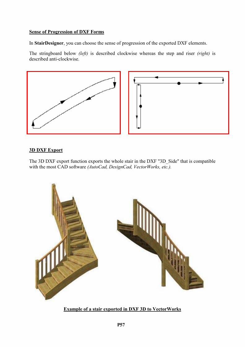
Sense of Progression of DXF Forms
In StairDesigner, you can choose the sense of progression of the exported DXF elements.
The stringboard below (left) is described clockwise whereas the step and riser (right) is
described anti-clockwise.
3D DXF Export
The 3D DXF export function exports the whole stair in the DXF "3D_Side" that is compatible
with the most CAD software (AutoCad, DesignCad, VectorWorks, etc.).
Example of a stair exported in DXF 3D to VectorWorks