Embed Size (px)
Citation preview

MDT technologies GmbH • 51766 Engelskirchen • Papiermühle 1 Tel.: +49-2263-880 • Fax: +49-2263-4588 • [email protected] • www.mdt.de
Stand 6/2014
Technical Manual
MDT 1-10V Control Device
AKD – 0410V.02

Technical Manual 1‐10V Control Device AKD – 0410V.02
MDT technologies GmbH • 51766 Engelskirchen • Papiermühle 1 Tel.: +49-2263-880 • Fax: +49-2263-4588 • [email protected] • www.mdt.de 2
1Content 1 Content ................................................................................................................................................. 2
2 Overview ............................................................................................................................................... 4
2.1 Overview Devices .......................................................................................................................... 4
2.2 Structure & Handling ..................................................................................................................... 4
2.3 Usage and Areas of Application..................................................................................................... 5
2.4 LEDs and manual control ............................................................................................................... 5
2.5 Settings at the ETS‐Software ......................................................................................................... 6
2.6. Starting up .................................................................................................................................... 6
3 Usage as 1‐10V Dimmer ....................................................................................................................... 7
3.1 Circuit Diagram .............................................................................................................................. 7
3.2 Communication Objects ................................................................................................................ 8
3.2.1 Summary and Usage ............................................................................................................... 8
3.2.2 Default settings of the communication objects ................................................................... 12
3.3 Reference ETS‐Parameter ........................................................................................................... 13
3.3.1 Channel Activation ............................................................................................................... 13
3.3.2 Handling/ basic functions ..................................................................................................... 14
3.3.3 Time functions ...................................................................................................................... 15
3.3.4 Staircase light ....................................................................................................................... 16
3.3.5 Absolute Values .................................................................................................................... 19
3.3.6 specific Dimming settings ..................................................................................................... 21
3.3.7 Central objects...................................................................................................................... 23
3.3.8 Scene function ...................................................................................................................... 24
3.3.9 Automatic function ............................................................................................................... 28
3.3.10 Additional functions ........................................................................................................... 30

Technical Manual 1‐10V Control Device AKD – 0410V.02
MDT technologies GmbH • 51766 Engelskirchen • Papiermühle 1 Tel.: +49-2263-880 • Fax: +49-2263-4588 • [email protected] • www.mdt.de 3
4 Controlling LED Stripes ....................................................................................................................... 33
4.1 Circuit Diagram ............................................................................................................................ 33
4.2 Communication Objects .............................................................................................................. 34
4.2.1 Overview and Usage ............................................................................................................. 34
4.2.2 Default settings of the communication objects ................................................................... 40
4.3 Color circle presentation/ Controlling via RGBW ........................................................................ 41
4.4 Reference ETS‐Parameter ........................................................................................................... 42
4.4.1 Selection of the way of controlling....................................................................................... 42
4.4.2 LED RGB/RGBW Settings ...................................................................................................... 44
4.4.3 LED RGB/RGBW Sequences .................................................................................................. 48
4.4.4 LED RGB/RGBW Bit Scenes ................................................................................................... 55
4.4.5 LED RGB/RGBW Scenes ........................................................................................................ 57
5 Index ................................................................................................................................................... 61
5.1 List of Illustrations ....................................................................................................................... 61
5.2 List of Tables ................................................................................................................................ 62
6 Attachment ......................................................................................................................................... 64
6.1 Statutory requirements ............................................................................................................... 64
6.2 Routine disposal .......................................................................................................................... 64
6.3 Assemblage .................................................................................................................................. 64
6.4 Datasheet .................................................................................................................................... 65

Technical Manual 1‐10V Control Device AKD – 0410V.02
MDT technologies GmbH • 51766 Engelskirchen • Papiermühle 1 Tel.: +49-2263-880 • Fax: +49-2263-4588 • [email protected] • www.mdt.de 4
2Overview 2.1OverviewDevices The Manual refers to the following 1‐10V Control devices (Order number is printed in bold letters):
AKD‐0410V.02 1‐10V Control Device MDRC, 4fold, 1‐10V Control Voltage o For Controlling 1‐10V ECGs, with built in relays, adjustable dimming speeds, Min‐
/Max‐Values adjustable o For Controlling RGBW‐Stripes via PWM‐Controller, Min‐/Max‐Values adjustable,
Dimming Speeds and transitions adjustable, up to 5 scenes adjustable, scens can be controlled via Byte or
2.2Structure&Handling
Figure 1: Structure Hardware

Technical Manual 1‐10V Control Device AKD – 0410V.02
MDT technologies GmbH • 51766 Engelskirchen • Papiermühle 1 Tel.: +49-2263-880 • Fax: +49-2263-4588 • [email protected] • www.mdt.de 5
The 1‐10V Control device AKD‐0410V.02 contains of up to four 1‐10V Outputs for controlling 1‐10V devices. Furthermore LED PWM driver for RGB‐ or RGBW‐Stripes can be controlled by the 1‐10V Control device. The AKD‐0410V.02 has two terminal blocks. The upper terminal block, internal connected to the relays, can switch the power supplies of the LED Stripes or the 1‐10V ECGs for avoiding standby consumption. The 1‐10V control voltage is connected to the lower terminal block. The circuit diagram differs due to the usage (controlling 1‐10V ECGs and controlling RGB/RGBW Stripes) and can be seen in the appropriate sections 3.1 and 4.1 . Manual dimming of the connected load can be done with the buttons for manual control at the top of the device. The buttons left/right are for channel selection and the buttons up/down are for dimming the selected channel. Attention: At controlling RGB/RGBW‐Stripes, only the first relays output is used (have a look at 4.1 ). So only the first channel indicates an active/inactive state. But the dimming of each color can be done in the normal way.
2.3UsageandAreasofApplication The AKD‐0410V.02 can be used as well for controlling 1‐10V as for controlling RGB/RGBW‐Stripes. For controlling RGB/RGBW‐Stripes, an additional PWM Controller with 1‐10V input is necessary. The parameter can be adjusted for both usages individually. There are a huge number of options for adjusting the dimming process as e.g. dimming speeds, transition speed, On‐/Off‐Behavior… By controlling RGB/RGBW‐Stripes, additional complex sequences can be parameterized. Furthermore the AKD‐0410V.02 contains of a large scene function and different automatic functions.
2.4LEDsandmanualcontrol The single channels can be switched on or off as well as be dimmed up or down via the hand control. The buttons left/right are for the selection of the channel. A chosen channel is indicated by its status LED. These LEDs can show the following conditions:
LED behavior State of the channel
LED shines permanent Channel is in use
LED is permanent off Channel is switched off
LED flashes with the frequency of 2:1 „long on‐ short off“
Channel is switched on and chosen by the hand control
LED flashes with frequency of 1:2 „short on‐ long off“
Channel is switched off and chosen by the hand control
Table 1: Display behavior of the green LED
By the keys up/down, the channels can be switched and dimmed. A short keystroke at the button “up” switches the channel off, a short keystroke at the button “up” switches the channel on. With a long keystroke, the chosen channel can be dimmed. As long as the “up‐button” is pressed, the channel is dimmed brighter. By a long keystroke at the button “down”, the channel is dimmed darker. The dimming process is stopped, when the channel reaches 100% or the button is released.

Technical Manual 1‐10V Control Device AKD – 0410V.02
MDT technologies GmbH • 51766 Engelskirchen • Papiermühle 1 Tel.: +49-2263-880 • Fax: +49-2263-4588 • [email protected] • www.mdt.de 6
2.5SettingsattheETS‐Software Selection at the product database: Manufacturer: MDT Technologies Product family: Actuators Product type: Dimming actuators Medium Type: Twisted Pair (TP) Product name: addicted to the used type, e.g.: AKD‐0410V.02 Order number: addicted to the used type, e.g.: AKD‐0410V.02
2.6.Startingup After wiring, the allocation of the physical address and the parameterization of every channel follow:
(1) Connect the interface with the bus, e.g. MDT USB interface (2) set bus power up (3) Press the programming button at the device(red programming LED lights) (4) Loading of the physical address out of the ETS‐Software by using the interface(red LED goes
out, as well this process was completed successful) (5) Loading of the application, with requested parameterization (6) If the device is enabled you can test the requested functions(also possible by using the ETS‐
Software)

Technical Manual 1‐10V Control Device AKD – 0410V.02
MDT technologies GmbH • 51766 Engelskirchen • Papiermühle 1 Tel.: +49-2263-880 • Fax: +49-2263-4588 • [email protected] • www.mdt.de 7
3Usageas1‐10VDimmer If the AKD‐0401V.02 should be used as “normal” 1‐10V Dimmer, the following settings must be made in the Menu “Global Settings”:
Figure 2: Function Selection 1‐10V Dimmer
So the Application for the 1‐10V Dimmer with all relevant parameters and communication objetcs is loaded.
3.1CircuitDiagram
Figure 3: Circuit Diagram 1‐10V ECG

Technical M
anual 1‐10V Control D
evice AKD – 0410V.02
M
DT
te
chn
olo
gie
s G
mb
H •
51
766
Eng
elsk
irche
n •
Pap
ierm
ühle
1
• T
el.:
+49
-226
3-8
80 •
Fax
: +49
-226
3-45
88
• kn
x@m
dt.d
e •
w
ww
.mdt
.de
8
3.2Com
municationObjects
3.2.1SummaryandUsage
Nr.
Nam
e
Object function
Data type
Direction
Info
Usage
Tip
Central Objects:
60
Cen
tral
Switch
DPT 1.001
receive
Actuator reacts to
Incoming‐telegram
Push buttons,
Visu...
for manual
control
This Communication is shown
perm
anently and allows the
controlling of the m
ain function
Switch On/O
ff for all chan
nels
with activated central function,
which is norm
ally connected to
all desired
control keys.
61
Cen
tral
Dim
absolutely
DPT 5.001
receive
Actuator reacts to
Incoming‐telegram
Push buttons,
Visu...
for manual
control
This Communication is shown
perm
anently and allows the
controlling of the m
ain function
Dim
Absolutely for all chan
nels
with activated central function,
which is norm
ally connected to
all desired
control keys.

Technical M
anual 1‐10V Control D
evice AKD – 0410V.02
M
DT
te
chn
olo
gie
s G
mb
H •
51
766
Eng
elsk
irche
n •
Pap
ierm
ühle
1
• T
el.:
+49
-226
3-8
80 •
Fax
: +49
-226
3-45
88
• kn
x@m
dt.d
e •
w
ww
.mdt
.de
9
Objects per Chan
nel:
0
Channel A
Switch
DPT 1.001
receive
Actuator reacts to
Incoming‐telegram
Push buttons,
Visu...
for manual
control
This Communication Object is
for controlling the main
function Switch On/O
ff for this
chan
nel, which is norm
ally
connected to all desired control
keys.
1
Channel A
Staircase
DPT 1.001
receive
Actuator reacts to
Incoming‐telegram
Push buttons,
Visu...
for manual
control
This Communication Object is
for controlling the main
function Staircase for this
chan
nel, which is norm
ally
connected to all desired control
keys.
2
Channel A
Dim
relatively
DPT 3.007
receive
Actuator reacts to
Incoming‐telegram
Push buttons,
Visu...
for manual
control
This Communication Object is
for controlling the main
function Dim
Up/D
own for this
chan
nel, which is norm
ally
connected to all desired control
keys.
3
Channel A
Dim
absolutely
DPT 5.001
receive
Actuator reacts to
Incoming‐telegram
Push buttons,
Visu...
for manual
control
This Communication Object is
for controlling the main
function Dim
absolutely for this
chan
nel, which is norm
ally
connected to all desired control
keys.

Technical M
anual 1‐10V Control D
evice AKD – 0410V.02
M
DT
te
chn
olo
gie
s G
mb
H •
51
766
Eng
elsk
irche
n •
Pap
ierm
ühle
1
• T
el.:
+49
-226
3-8
80 •
Fax
: +49
-226
3-45
88
• kn
x@m
dt.d
e •
w
ww
.mdt
.de
10
4
Channel A
State On/O
ff
DPT 1.011
sending
Actuator sends
curren
t state
For display on
Visu, Tableau,
and Display
This Communication Object is
shown when the chan
nel is
active and can
be used for
showing the sw
itching state
On/O
ff of this channel.
5
Channel A
State Dim
value
DPT 5.001
sending
Actuator sends
curren
t state
For display on
Visu, Tableau,
and Display
This Communication Object is
only shown after activating in
the param
eter settings and can
be used as status indication.
(= Additional function if
desired)
6
Channel A
Block 1
DPT 1.003
receive
Actuator reacts to
Incoming‐telegram
Push buttons,
Visu...
for manual
control
This Communication Object is
shown when the chan
nel is
active and can
be used for
blocking this channel.
(= Additional function if
desired)
7
Channel A
Block 2
DPT 1.003
receive
Actuator reacts to
Incoming‐telegram
Push buttons,
Visu...
for manual
control
This Communication Object is
shown when the chan
nel is
active and can
be used for an
extended
blocking function.
(= Additional function if
desired)

Technical M
anual 1‐10V Control D
evice AKD – 0410V.02
M
DT
te
chn
olo
gie
s G
mb
H •
51
766
Eng
elsk
irche
n •
Pap
ierm
ühle
1
• T
el.:
+49
-226
3-8
80 •
Fax
: +49
-226
3-45
88
• kn
x@m
dt.d
e •
w
ww
.mdt
.de
11
8
Channel A
Scen
e
DPT 18.001
receive
Actuator reacts to
Incoming‐telegram
Push buttons,
Visu...
for manual
control
This Communication Object is
only shown after activating in
the param
eter settings and can
be used for calling scen
es.
(= Additional function if
desired)
11‐14
Channel A
Automatic 1‐4
DPT 1.017
receive
Actuator reacts to
Incoming‐telegram
Push buttons,
Visu...
for manual
control
This Communication Object is
only shown after activating in
the param
eter settings and can
be used for calling of absolute
brightness values with a 1 Bit
command.
(= Additional function if
desired)
Table 2: C
ommunication Objects Application Dim
mer 1‐10V

Technical Manual 1‐10V Control Device AKD – 0410V.02
MDT technologies GmbH • 51766 Engelskirchen • Papiermühle 1 Tel.: +49-2263-880 • Fax: +49-2263-4588 • [email protected] • www.mdt.de 12
3.2.2Defaultsettingsofthecommunicationobjects
Default Settings
Nr. Name Object Function Length Priority C R W T U
0 Channel A Switch 1 Bit Low X X
1 Channel A Staircase 1 Bit Low X X
2 Channel A Dim relative 4 Bit Low X X
3 Channel A Dim absolutely 1 Byte Low X X
4 Channel A State On/Off 1 Bit Low X X X
5 Channel A State dim value 1 Byte Low X X X
6 Channel A Block I 1 Bit Low X X
7 Channel A Block II 1 Bit Low X X
8 Channel A Scene 1 Byte Low X X
11 Channel A Automatic 1 1 Bit Low X X
12 Channel A Automatic 2 1 Bit Low X X
13 Channel A Automatic 3 1 Bit Low X X
14 Channel A Automatic 4 1 Bit Low X X
+15 next Channel
60 Central Switch 1 Bit Low X X
61 Central Dim absolutely 1 Byte Low X XTable 3: Default Settings Communication Objects (Dimmer 1‐10V)
You can see the default values for the communication objects from the upper chart. According to
requirements the priority of the particular communication objects as well as the flags can be
adjusted by the user. The flags allocates the function of the objects in the programming thereby
stands C for communication, R for Read, W for write, T for transmit and U for update.

Technical Manual 1‐10V Control Device AKD – 0410V.02
MDT technologies GmbH • 51766 Engelskirchen • Papiermühle 1 Tel.: +49-2263-880 • Fax: +49-2263-4588 • [email protected] • www.mdt.de 13
3.3ReferenceETS‐Parameter
3.3.1ChannelActivation Every channel can be activated or deactivated individually. This setting can be done at the submenu channel activation:
Figure 4: Channel activation
The chart shows the dynamic range for this parameter:
ETS‐text Dynamic range [default value]
comment
Channel A‐[D] not active
active
Activation of the depending channel
Table 4: Channel activation
When a channel is activated, a new submenu is shown at the left selection menu. By choosing the submenu for this channel, the further parameterization can be done. Furthermore, a new submenu, with additional functions according the channel, is shown and the depending communication objects are shown. A channel, which is chosen as “not active”, cannot be parameterized. There are no communication objects shown for deactivated channels.

Technical Manual 1‐10V Control Device AKD – 0410V.02
MDT technologies GmbH • 51766 Engelskirchen • Papiermühle 1 Tel.: +49-2263-880 • Fax: +49-2263-4588 • [email protected] • www.mdt.de 14
3.3.2Handling/basicfunctions The basic functions of the dimming actuator are divided in three sections: Switching, dimming relatively and dimming absolutely. As soon as a channel is activated, the communication functions for the basic functions are standardly shown.
3.3.2.1Switching A channel can be switched on or off by the switching command. Additional there is a state object, which shows the actual switching state of the output. This object, State On/Off, can be used for visualization. When the actuator shall be switched by a binary input or a push button, this object must be connected with the state object of the binary input or the push button for toggling.
Number Name Length Usage0 Switch 1 Bit switches the channel on or off
4 State On/Off 1 Bit shows the switching state of the channel Table 5: Communication objects switching
3.3.2.2Dimrelatively The relative dimming allows continuous dimming. So the lights can be dimmed evenly form 0% to 100% or from 100% to 0%. The relative dimming process can be stopped at every state. The behavior of the dimming process can be adjusted via additional parameters, like dim speed.
Number Name Length Usage2 Dim relatively 4 Bit dims the channel continuous up and down Table 6: Dim relatively
3.3.2.3Dimabsolutely A discrete brightness level can be set by the absolute dimming process. By sending an absolute percent value to the 1 Byte object “Dim absolutely”, the output assumes a certain brightness level.
Number Name Length Usage3 Dim absolutely 1 Byte adjusts a certain brightness level Table 7: Dim absolutely

Technical Manual 1‐10V Control Device AKD – 0410V.02
MDT technologies GmbH • 51766 Engelskirchen • Papiermühle 1 Tel.: +49-2263-880 • Fax: +49-2263-4588 • [email protected] • www.mdt.de 15
3.3.3Timefunctions The dimming actuator has the opportunities of connecting different time functions. Besides the normal on‐/off‐ delay an additional staircase function with different sub functions is available.
3.3.3.1On‐/Offdelay The on‐ and off‐delay allows a delayed switching. The following chart shows this parameter:
Figure 5: On‐/Off‐delay
The chart shows the dynamic range for this parameter:
ETS‐text Dynamic range [default value]
comment
On delay/ Off delay
no delay, 1s,5s,10s,15s,20s,30s,45s,60s
2min,3min,4min,5min,6min,7min,8min, 9min,10min,15min,20min,30min,45min,60min
Adjustment of the time at which the switch‐on/ switch off process shall be delayed
Table 8: On‐/Off‐delay
By using the on‐delay and off‐delay, switching commands can be delayed. The delay can affect only to the rising edge (switch‐on delay) or the falling edge (switch‐off delay). Furthermore, both functions can be combined. The following diagram shows the functional principle of both functions, which are activated in this example:

Technical Manual 1‐10V Control Device AKD – 0410V.02
MDT technologies GmbH • 51766 Engelskirchen • Papiermühle 1 Tel.: +49-2263-880 • Fax: +49-2263-4588 • [email protected] • www.mdt.de 16
3.3.4Staircaselight Staircase light allows an automatic off‐switching of the channel, when the adjusted time runs out. To parameterize this function, the staircase light must be activated at the corresponding channel:
Figure 6: Staircase light activation

Technical Manual 1‐10V Control Device AKD – 0410V.02
MDT technologies GmbH • 51766 Engelskirchen • Papiermühle 1 Tel.: +49-2263-880 • Fax: +49-2263-4588 • [email protected] • www.mdt.de 17
If the staircase light is activated, a new sub menu, called staircase light Channel A‐[D] is shown at the left selection menu. At this sub menu, the further parameterization can be done.
Figure 7: Staircase light
The chart shows the dynamic range for this parameter:
ETS‐text Dynamic range [default value]
comment
Duration of staircase 0‐30.000s [90s]
Duration of the switching process
Prewarning active
not active
activates the prewarning
Prewarning duration in [s]
0‐30.000 [0s]
is only shown, when the prewarning is activated
Value of dimming down
1‐100% [20%]
is only shown, when the prewarning is activated Value of which the channel shall be dimmed down, when the staircase time ran out
Extension active
not active
Activation of a possible extension of the staircase light
Deactivation active
not active
Activation of Deactivation of the staircase light, before the whole time ran out
Table 9: Staircase light

Technical Manual 1‐10V Control Device AKD – 0410V.02
MDT technologies GmbH • 51766 Engelskirchen • Papiermühle 1 Tel.: +49-2263-880 • Fax: +49-2263-4588 • [email protected] • www.mdt.de 18
The duration of the staircase light indicates how long the channel shall be switched on after an On‐signal. After lapse of time, the channel is switched off automatically. Via the parameter Extension/ deactivation, the staircase function can be modified. The deactivation allows switching off the channel before the time ran out. The extension allows an extension of the staircase time, by sending another on‐telegram, so the time is restarted. The prewarning function creates a dimming down of the lights after expiration of the staircase time. So the lights are still switched on, but with another value. The lights stay at this position for the duration of the prewarning. If the staircase function is activated, the communication object “Switch” is replaced by the communication object “Staircaselight”:
Number Name Length Usage1 Staircaselight 1 Bit switches the staircase function on Table 10: Communication object staircaselight
The staircase function has no influence to the relative or absolute dimming. At the following diagram, the staircase function is shown, with an activated deactivation and extension. The prewarning is activated with a dim down value of 20%:

Technical Manual 1‐10V Control Device AKD – 0410V.02
MDT technologies GmbH • 51766 Engelskirchen • Papiermühle 1 Tel.: +49-2263-880 • Fax: +49-2263-4588 • [email protected] • www.mdt.de 19
3.3.5AbsoluteValues The dimming area of the dimming actuator can be restricted by absolute values. Furthermore absolute or saved values can be called, when the actuator is switched on.
3.3.5.1Startingbehavior The function starting behavior defines the turn off of the channel. The function is parameterize able for every channel individually. The following illustration shows the function with the setting „On‐value setting”:
Figure 8: Starting behavior
The chart shows the dynamic range for this parameter:
ETS‐text Dynamic range [default value]
comment
On‐value setting Sub‐function: Value of start up 1‐100% [100%]
If this sub‐function is chosen, a new sub‐function is shown, at which an absolute value for switching on can be chosen
Last light value (Memory) The channel starts with the last value before switching off
Start up speed/Switch off speed (from hardware version 2.0F)
1s – 240s [1s]
Soft‐Start/‐stop function defines the time for dimming up to the adjusted value after witched on/ for dimming down after switched off
Table 11: Starting behavior
Via the parameter “Value for startup” an absolute value for switching on, can be assigned to the channel. The value for startup contains the whole technical possible area, so form 1‐100%. But if the dimming area is restricted, the dimming actuator will be at least switched on with the lowest allowed value and maximum with the highest allowed value; independent from the chosen Value of startup. The parameter “Last light value“, also called “memory function”, causes a switching on of the actuator with the value before the last switching off. So the actuator saves the last value. If, for example, the channel is dimmed to 50% and switched off afterwards, the channel will be switched on with 50% again. The parameterization of the starting behavior affects only to the switching objects, so the objects 0: Switch or 1: Staircase light. If the channel is dimmed up from a power off condition, the channel will be dimmed normal up without any startup behavior.

Technical Manual 1‐10V Control Device AKD – 0410V.02
MDT technologies GmbH • 51766 Engelskirchen • Papiermühle 1 Tel.: +49-2263-880 • Fax: +49-2263-4588 • [email protected] • www.mdt.de 20
3.3.5.2Dimmingarea Via the parameters “minimum light” and “maximum light” the dimming area can be restricted.
Figure 9: Dimming area
The chart shows the dynamic range for this parameter:
ETS‐text Dynamic range [default value]
comment
Minimum light 1‐100% [1%]
lowest, minimum allowed light value
Maximum light 1‐100% [100%]
highest, maximum allowed light value
Table 12: Dimming area
If the technical possible dimming area (1‐100%) shall be restricted to a lower area, you have to set
values for the minimum light above 1% and for the maximum light under 100%. This restriction of the dimming area is possible for every channel. If the dimming area is restricted, the channel will only move in the adjusted restriction. This setting has also effects to the other parameter: If for example the channel is restricted to a maximum of 85% and the value of startup is chosen as 100%, the channel will switch on with the maximum of 85%. An exceed of the maximum value is no longer possible. The restriction of a dimming area is useful when certain values must not be reached, because of technical reasons, for example preservation of the life span or the avoidance of flickering at lower dim values (especially at Energy saver).
Example: Minimum light = 25%, maximum light = 85%, Value for startup= 100%
On telegram ‐‐> adjusted light value 85%
50% telegram ‐‐> adjusted light value 50%
95% telegram ‐‐> adjusted light value 85%
15% telegram ‐‐> adjusted light value 25%
Off telegram ‐‐> adjusted light value 0% (Off)

Technical Manual 1‐10V Control Device AKD – 0410V.02
MDT technologies GmbH • 51766 Engelskirchen • Papiermühle 1 Tel.: +49-2263-880 • Fax: +49-2263-4588 • [email protected] • www.mdt.de 21
3.3.6specificDimmingsettings The dimming behavior can be adapted individually via the dimming speed. Additional a status object can be activated for visualization.
Figure 10: Specific dimming settings
3.3.6.1Dimmingspeed The dimming speed allows parameterizing the duration of the dimming process individually. The chart shows the dynamic range for this parameter:
ETS‐text Dynamic range [default value]
comment
Dimming speed[s] 1‐120s [5s]
indicates the time, which is need for dimming form 0 to 100%
Table 13: Dimming speed
The dimming process can be adapted individually via the setting of the dimming speed. A very long dimming speed allows a very precise dimming. So, almost every dimming value can be controlled. A short adjusted dimming speed causes a fast dimming process. This setting is useful, when it is not necessary to adjust the light very precise or the vernier adjustment is performed by using absolute values, which are switch independent of the dimming speed directly to the adjusted value. Normally values from 5‐8s are used for normal used rooms.

Technical Manual 1‐10V Control Device AKD – 0410V.02
MDT technologies GmbH • 51766 Engelskirchen • Papiermühle 1 Tel.: +49-2263-880 • Fax: +49-2263-4588 • [email protected] • www.mdt.de 22
3.3.6.2Senddimmingvalueafterchange To visualize the dimming value, for example via a display, the following communication object must be activated: ETS‐text Dynamic range
[default value] comment
Send dimming value after change (min. 2%)
not active
active
activates the status object for the dimming process
Table 14: Send dimming value after change
The communication object for the actual dimming value is shown continuous, but sends only the actual dimming value, when the parameter “Send dimming value after change” is activated. The object of the size 1 Byte sends now the current dimming value at a change of 2% and more.
Number Name Length Usage5 State dim value 1 Byte sends the actual dimming value in % Table 15: Communication object dimming value

Technical Manual 1‐10V Control Device AKD – 0410V.02
MDT technologies GmbH • 51766 Engelskirchen • Papiermühle 1 Tel.: +49-2263-880 • Fax: +49-2263-4588 • [email protected] • www.mdt.de 23
3.3.7Centralobjects For each channel can be chosen, whether it should react to the central objects or not. The activation of the central objects can be done at the following parameter:
Figure 11: Central objects
If the central function is activated for a channel, the channel will react to the central objects with its individual parameterization. The chart shows the dynamic range for this parameter: ETS‐text Dynamic range
[default value] comment
Central objects not active
active
sets whether a channel shall react to the central objects or not
Table 16: Central objects
There are two central objects for the handling of the activated channels. At the one hand the 1 Bit switching object, which switches the channels with activated central function on or off and to the other hand the 1 Byte object “Dim absolutely”. This object assigns absolute light values to the relevant channels. To watch at the central objects is, that every channel is called with its individually parameter settings. If for example a channel with activated staircase light function is called by the central objects, the channel will be switched on for the adjusted staircase time and will be switched off afterwards.
Number Name Object function Length Usage60 Central Switch 1 Bit switches all channels with activated central
function
61 Central Dim absolutely 1 Byte dims all channels with activated central function Table 17: Central communication objects
The communication object “device error“ is independent from the parameter “central objects”. The object sends an 1‐signal, if an error occurs at the device.
Number Name Object function Length Usage62 Central Device error 1 Bit sends a 1‐signal in case of an error Table 18: Central communication object device error

Technical Manual 1‐10V Control Device AKD – 0410V.02
MDT technologies GmbH • 51766 Engelskirchen • Papiermühle 1 Tel.: +49-2263-880 • Fax: +49-2263-4588 • [email protected] • www.mdt.de 24
3.3.8Scenefunction When functions of different groups (e.g. light, heating and shutter) shall be changed simultaneously with only one keystroke, it is practical to use the scene function. By calling a scene, you can switch the lights to a specific value, drive the shutter to an absolute position, switch the heating to the day mode and switch the power supply of the sockets on. The telegrams of these functions can have as well different formats as different values with different meaning (e.g. “0” for switch the lights off and open the shutters). If there were no scene function, you would have to send a single telegram for every actuator to get the same function. The scene function of the switch actuator enables you to connect the channels of the switch actuator to a scene control. For that, you have to assign the value to the appropriated space (scene A..H). It is possible to program up to 8 scenes per switching output. When you activate the scene function at the switching output, a new sub menu for the scenes appears at the left drop down menu. There are settings to activate single scenes, set values and scene numbers and switch the memory function on/off at this sub menu. Scenes are activated by receiving their scene numbers at the communication object for the scenes. If the memory function of the scenes is activated, the current value of the channel will be saved at the called scene number. The communication objects of the scenes have always the length of 1 byte. The following illustration shows the setting options at the ETS‐Software for activating the scene function:
Figure 12: Scene function
The scene function can only be activated for the normal switching mode. If the staircase light function is activated, the scene function cannot be activated for this channel. The following chart shows the communication object for calling a scene:
Number Name Length Usage8 Scene 1 Byte Call of the scene Table 19: Communication object scene
For calling a certain scene, you have to send the value for the scene to the communication object. The value of the scene number is always one number less than the adjusted scene number. For calling scene 1, you have to send a “0”. So the scene numbers have the numbers from 1 to 64, but the values for the scenes only from 0 to 63. If you want to call scenes by a binary input or another KNX device, you have to set the same number at the calling device as at the receiving device. The calling device, e.g. a binary input, sends automatically the right value for calling the scene.

Technical Manual 1‐10V Control Device AKD – 0410V.02
MDT technologies GmbH • 51766 Engelskirchen • Papiermühle 1 Tel.: +49-2263-880 • Fax: +49-2263-4588 • [email protected] • www.mdt.de 25
3.3.8.1Submenuscene If a scene is activated, as shown above, a new submenu will appear at the left selection menu. At this submenu, the further parameterization can be done. For every channel are up to 8 storage options available. These 8 presets have numbers A‐H. One of the 64 scene numbers can be assigned to each scene. The following illustration shows the setting options at the submenu for the scenes (Channel X: Scene) for the scenes A‐C (the scenes D‐H are identical with first three):
Figure 13: Submenu scene
The following chart shows the dynamic range for an activated scene function:
ETS‐text Dynamic range [default value]
comment
Save scene disabled
enabled
adjusts whether the saving function shall be enabled for the scenes of this channel or not
Scene Nr. A‐[H] 1‐64, inactive [inactive]
adjusts the number for calling a scene
Light value scene A‐[H] Off, 10%, 20%, 30%, 40%, 50%, 60%, 70%, 80%, 90%, 100% light
[Off]
adjusts the light value for a scene call
Table 20: Submenu scene

Technical Manual 1‐10V Control Device AKD – 0410V.02
MDT technologies GmbH • 51766 Engelskirchen • Papiermühle 1 Tel.: +49-2263-880 • Fax: +49-2263-4588 • [email protected] • www.mdt.de 26
At the submenu for the scenes, a reaction can be assigned for the call of each scene. This reaction includes an absolute light value (0‐100%) for this channel. Every channel can react to 8 different scenes. By sending of the pick‐up value of the relevant scene, the scene is called and the channel adjusts its parameterized values. The individual parameterization is also watched at calling the scene. If the channel shall dim to 50% at the call of the scene A and the channel has a parameterized switch‐on delay of 5s, the channel will be switched on after this 5s and be dimmed to the 50% in compliance to the adjusted dimming speed. To watch at the programming is that if two or more channels shall react to the same scene number, the communication objects for the scenes of these channels have to be connected to the same group address. By sending of the pick‐up value for the scenes, all channels will be called. It is practical to divide the group addresses by scenes at the programming. If a channel shall react now to 8 scenes, the communication object has to be connected to 8 different group addresses.

Technical Manual 1‐10V Control Device AKD – 0410V.02
MDT technologies GmbH • 51766 Engelskirchen • Papiermühle 1 Tel.: +49-2263-880 • Fax: +49-2263-4588 • [email protected] • www.mdt.de 27
For calling a scene or saving a new value for the scene, you have to send the accordingly code to the relevant communication object for the scene:
Scene Retrieve Save Hex. Dez. Hex. Dez.
1 0x00 0 0x80 128
2 0x01 1 0x81 129
3 0x02 2 0x82 130
4 0x03 3 0x83 131
5 0x04 4 0x84 132
6 0x05 5 0x85 133
7 0x06 6 0x86 134
8 0x07 7 0x87 135
9 0x08 8 0x88 136
10 0x09 9 0x89 137
11 0x0A 10 0x8A 138
12 0x0B 11 0x8B 139
13 0x0C 12 0x8C 140
14 0x0D 13 0x8D 141
15 0x0E 14 0x8E 142
16 0x0F 15 0x8F 143
17 0x10 16 0x90 144
18 0x11 17 0x91 145
19 0x12 18 0x92 146
20 0x13 19 0x93 147
21 0x14 20 0x94 148
22 0x15 21 0x95 149
23 0x16 22 0x96 150
24 0x17 23 0x97 151
25 0x18 24 0x98 152
26 0x19 25 0x99 153
27 0x1A 26 0x9A 154
28 0x1B 27 0x9B 155
29 0x1C 28 0x9C 156
30 0x1D 29 0x9D 157
31 0x1E 30 0x9E 158
32 0x1F 31 0x9F 159 Table 21: Calling and saving scenes

Technical Manual 1‐10V Control Device AKD – 0410V.02
MDT technologies GmbH • 51766 Engelskirchen • Papiermühle 1 Tel.: +49-2263-880 • Fax: +49-2263-4588 • [email protected] • www.mdt.de 28
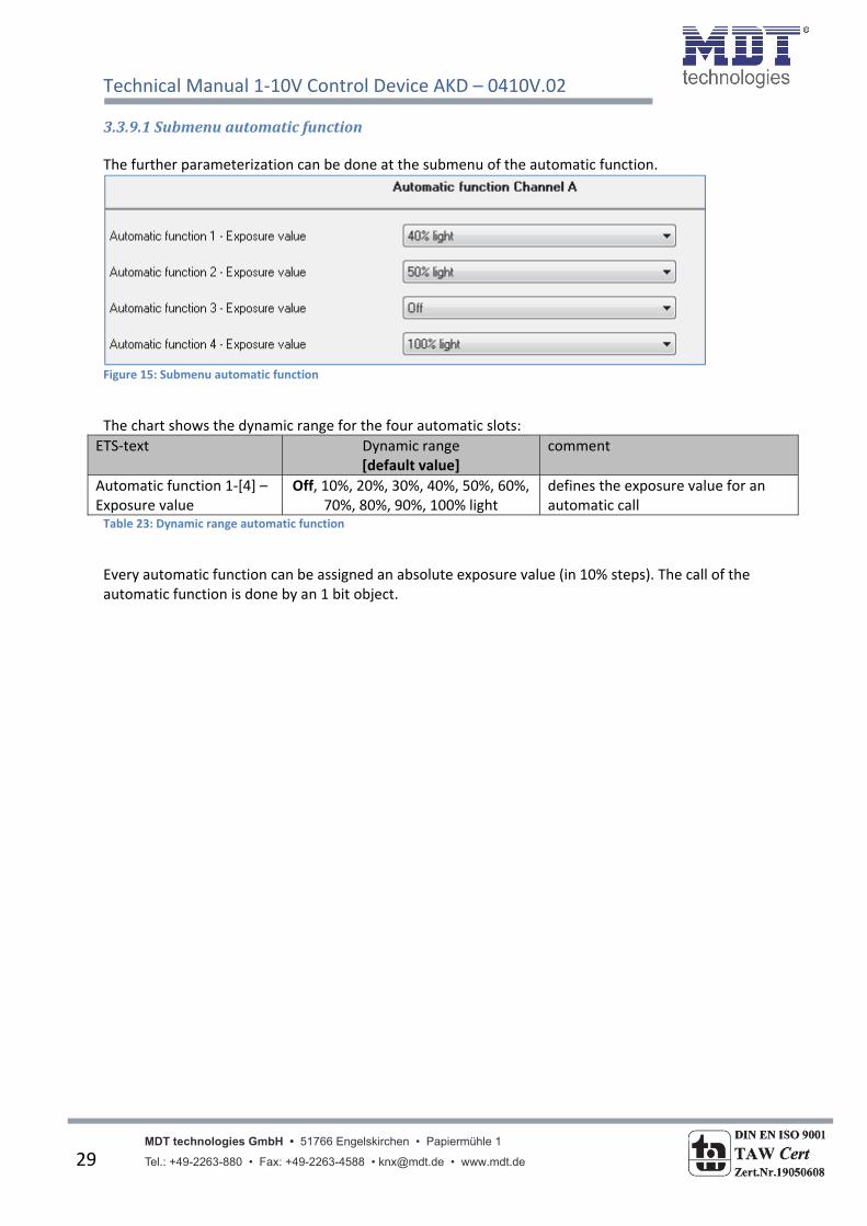
3.3.9Automaticfunction An automatic function can be activated for every channel. The automatic function allows calling up to 4 absolute exposure values for every channel. Calling can be done via a 1 bit commands. For further setting options, the automatic function of a channel must be activated.
Figure 14: Parameter Automatic function
By activation the automatic function a submenu for further parameterization is shown. Furthermore, the following communication objects are shown:
Number Name Length Usage11 Automatic 1 1 Bit Calling of the automatic value 1
12 Automatic 2 1 Bit Calling of the automatic value 2
13 Automatic 3 1 Bit Calling of the automatic value 3
14 Automatic 4 1 Bit Calling of the automatic value 4 Table 22: Communication objects automatic function
Technical Manual 1‐10V Control Device AKD – 0410V.02
MDT technologies GmbH • 51766 Engelskirchen • Papiermühle 1 Tel.: +49-2263-880 • Fax: +49-2263-4588 • [email protected] • www.mdt.de 29
3.3.9.1Submenuautomaticfunction The further parameterization can be done at the submenu of the automatic function.
Figure 15: Submenu automatic function
The chart shows the dynamic range for the four automatic slots:
ETS‐text Dynamic range [default value]
comment
Automatic function 1‐[4] – Exposure value
Off, 10%, 20%, 30%, 40%, 50%, 60%, 70%, 80%, 90%, 100% light
defines the exposure value for an automatic call
Table 23: Dynamic range automatic function
Every automatic function can be assigned an absolute exposure value (in 10% steps). The call of the automatic function is done by an 1 bit object.

Technical Manual 1‐10V Control Device AKD – 0410V.02
MDT technologies GmbH • 51766 Engelskirchen • Papiermühle 1 Tel.: +49-2263-880 • Fax: +49-2263-4588 • [email protected] • www.mdt.de 30
3.3.10Additionalfunctions Additional functions can be parameterized for every channel. Via the additional functions, the behavior of the channel for calling the blocking objects can be assigned. Furthermore, the behavior after power off and reset can be defined. The additional functions are shown at the submenu “Additional functions A‐[D]”:
Figure 16: Additional functions

Technical Manual 1‐10V Control Device AKD – 0410V.02
MDT technologies GmbH • 51766 Engelskirchen • Papiermühle 1 Tel.: +49-2263-880 • Fax: +49-2263-4588 • [email protected] • www.mdt.de 31
3.3.10.1Blockingobjects For both blocking objects an action for activation as well as deactivation can be defined.
ETS‐text Dynamic range [default value]
comment
Behavior at Block 1 = Value 1
Off, no change, Light value (10%,20%,30%,..,100%)
[no change]
Defines the action for activation of the first blocking object
Behavior at Block 1 = Value 0
Off, no change, Light value (10%,20%,30%,..,100%)
[no change]
Defines the action for deactivation of the first blocking object
Behavior at Block 2 = Value 1
Off, no change, Light value (10%,20%,30%,..,100%)
[no change]
Defines the action for activation of the second blocking object
Behavior at Block 2 = Value 0
Off, no change, Light value (10%,20%,30%,..,100%)
[no change]
Defines the action for deactivation of the second blocking object
Table 24: Dynamic range blocking objects
By using the blocking objects, the channel can be blocked for further usage. Additional, the channel can perform an adjusted function, as dimming to a certain value, switch the channel of or stay in its current state, when it is blocked. The same actions can be performed by the channel, when he is unblocked. To note is, that the channel cannot be operated when it is blocked. Furthermore the manual usage is blocked during a blocking process. All telegrams, which are sent to the corresponding channel during a blocking process, have no effect for the channel. If both blocking processes are activated, the first one is of prime importance. But if you activate the second blocking process during the first blocking process, the second blocking process will get active when the first one is deactivated. The action for the deactivation of the first blocking process will not be performed, but the channel calls the adjusted settings for the second blocking process. The communication objects for both blocking processes are shown at the following chart:
Number Name Length Usage6 Block 1 1 Bit Activation/Deactivation of the first blocking
process
7 Block 2 1 Bit Activation/Deactivation of the second blocking process
Table 25: Communication objects blocking

Technical Manual 1‐10V Control Device AKD – 0410V.02
MDT technologies GmbH • 51766 Engelskirchen • Papiermühle 1 Tel.: +49-2263-880 • Fax: +49-2263-4588 • [email protected] • www.mdt.de 32
3.3.10.2Behaviorafterpoweroff/afterreset To avoid an unintended behavior of the channel in case of bus power off, the channel can be parameterized for the case of a power off and a reset of the bus power. The following settings are available:
ETS‐text Dynamic range [default value]
comment
Behavior after power off no reaction, Off, 20%,35%,50%,65%,80%,100%
[no reaction]
defines the behavior at a bus power breakdown
Behavior after reset Off, On, last value, light value(10%,20%,30%,..,100%)
[last value]
defines the behavior at a bus power reset
Table 26: Behavior at bus power off/reset
Every channel can respond the bus power off with its individual parameterized settings. So a channel can be switched off, dim to absolute light values or respond with no reaction. Also for the reset, individual settings can be parameterized. The channel can be switched off, dim to a certain light value or calling the last light value, before power off, with the setting “last value”. Especially in rooms without other light sources or in rooms in which a failure off the lights can cause danger, you have to parameterize this setting conscientious.
Technical Manual 1‐10V Control Device AKD – 0410V.02
MDT technologies GmbH • 51766 Engelskirchen • Papiermühle 1 Tel.: +49-2263-880 • Fax: +49-2263-4588 • [email protected] • www.mdt.de 33
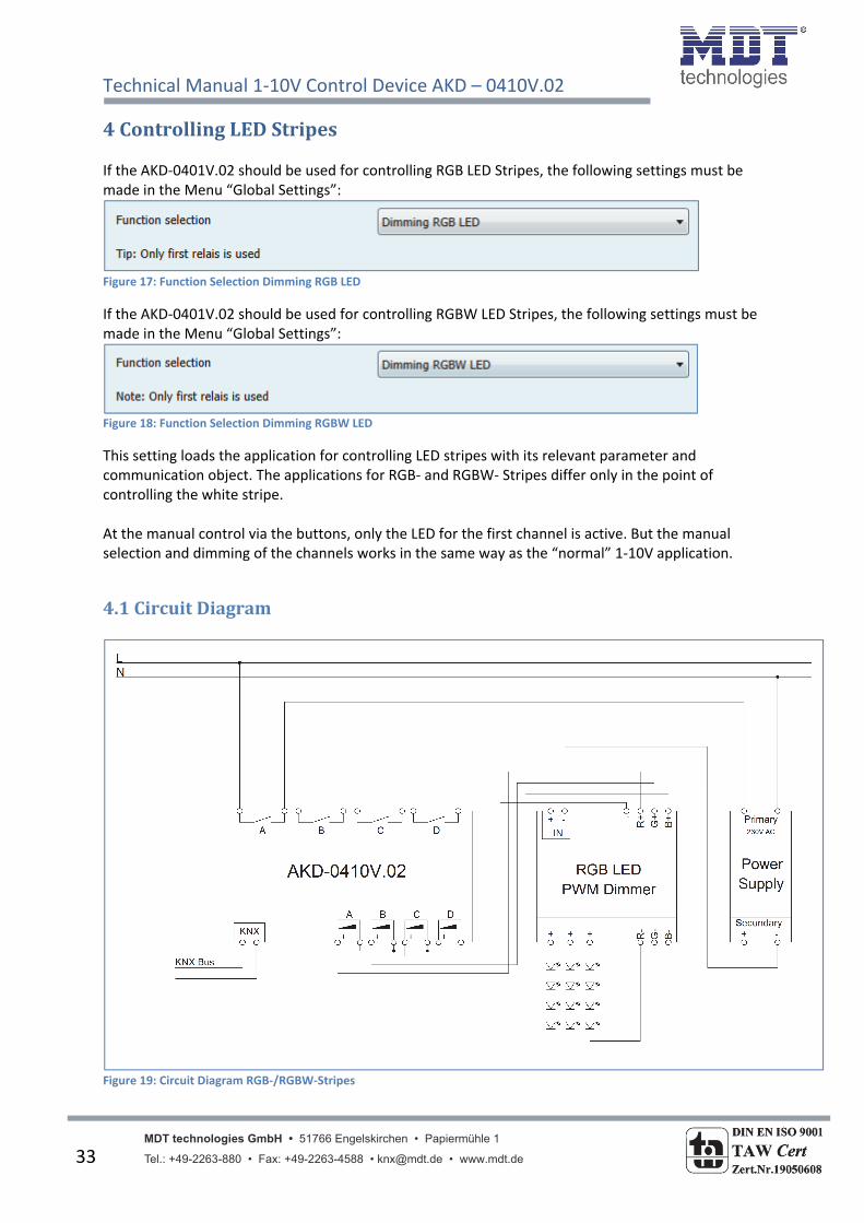
4ControllingLEDStripes If the AKD‐0401V.02 should be used for controlling RGB LED Stripes, the following settings must be made in the Menu “Global Settings”:
Figure 17: Function Selection Dimming RGB LED
If the AKD‐0401V.02 should be used for controlling RGBW LED Stripes, the following settings must be made in the Menu “Global Settings”:
Figure 18: Function Selection Dimming RGBW LED
This setting loads the application for controlling LED stripes with its relevant parameter and communication object. The applications for RGB‐ and RGBW‐ Stripes differ only in the point of controlling the white stripe. At the manual control via the buttons, only the LED for the first channel is active. But the manual selection and dimming of the channels works in the same way as the “normal” 1‐10V application.
4.1CircuitDiagram
Figure 19: Circuit Diagram RGB‐/RGBW‐Stripes

Technical M
anual 1‐10V Control D
evice AKD – 0410V.02
M
DT
te
chn
olo
gie
s G
mb
H •
51
766
Eng
elsk
irche
n •
Pap
ierm
ühle
1
• T
el.:
+49
-226
3-8
80 •
Fax
: +49
-226
3-45
88
• kn
x@m
dt.d
e •
w
ww
.mdt
.de
34
4.2Com
municationObjects
4.2.1OverviewandUsage
Nr.
Nam
e
Object function
Data type
Direction
Info
Usage
Tip
General O
bjects per Chan
nel:
63
LED RGB/RGBW
Switch
DPT 1.001
receive
Actuator reacts to
Incoming‐telegram
Push buttons,
Visu...
for manual
control
This Communication is shown
perm
anently and allows the
controlling of the m
ain function
LED Stripe On/O
ff, w
hich is
norm
ally connected to all
desired
control keys.
64
LED RGB/RGBW
Color Setting
DPT
232.600
receive
Actuator reacts to
Incoming‐telegram
Push buttons,
Visu...
for manual
control
This Communication Object is
shown if the controlling of the
LED Stripe is selected as
“RGB/RGBW” via the param
eter
settings. The Object allows the
controlling of the three colors
with only one object. The first
byte controls red
, the second
green and the third blue.
65
LED HSV
Color Setting
DPT
232.600
receive
Actuator reacts to
Incoming‐telegram
Push buttons,
Visu...
for manual
control
This Communication Object is
shown if the controlling of the
LED Stripe is selected as “H
SV”
via the param
eter settings. The
Object allows the controlling of
color circle with only one
object. The first byte controls
hue, the second saturation and
the third brightness.

Technical M
anual 1‐10V Control D
evice AKD – 0410V.02
M
DT
te
chn
olo
gie
s G
mb
H •
51
766
Eng
elsk
irche
n •
Pap
ierm
ühle
1
• T
el.:
+49
-226
3-8
80 •
Fax
: +49
-226
3-45
88
• kn
x@m
dt.d
e •
w
ww
.mdt
.de
35
72
LED RGB/RGBW
State ON/O
FF
DPT 1.011
send
Actuator sends
curren
t state
For display on
Visu, Tableau,
and Display
This Communication is shown
perm
anently and sen
ds the
state of the main function LED
Stripe On/O
ff, w
hich is
norm
ally connected to all
desired
display elem
ents.
81
LED RGB/RGBW
Block
DPT 1.003
receive
Actuator reacts to
Incoming‐telegram
Push buttons,
Visu...
for manual
control
This Communication is shown
perm
anently and can
be used
for blocking the actuator.
82
LED RGB/RGBW
Teach‐In for white
balance
DPT 1.001
receive
Actuator reacts to
Incoming‐telegram
Push buttons,
Visu...
for manual
control
This Communication is shown
perm
anently and starts the
white balance of the connected
LED Stripe.
Controlling via RGB/RGBW:
2/
17/
32/
47
LED
Red
/Green
/Blue/White
Change relative
DPT 3.007
receive
Actuator reacts to
Incoming‐telegram
Push buttons,
Visu...
for manual
control
This Communication Object is
shown if the controlling of the
LED Stripe is selected as
“RGB/RGBW” and can
be used
for relative dim
ming of each
color.
3/
18/
33/
48
LED
Red
/Green
/Blue/White
Change Absolute
DPT 5.001
receive
Actuator reacts to
Incoming‐telegram
Push buttons,
Visu...
for manual
control
This Communication Object is
shown if the controlling of the
LED Stripe is selected as
“RGB/RGBW” and can
be used
for absolute dim
ming of each
color.

Technical M
anual 1‐10V Control D
evice AKD – 0410V.02
M
DT
te
chn
olo
gie
s G
mb
H •
51
766
Eng
elsk
irche
n •
Pap
ierm
ühle
1
• T
el.:
+49
-226
3-8
80 •
Fax
: +49
-226
3-45
88
• kn
x@m
dt.d
e •
w
ww
.mdt
.de
36
Controlling via HSV
:
66
LED H (Hue)
Absolute Value
DPT 5.001
receive
Actuator reacts to
Incoming‐telegram
Push buttons,
Visu...
for manual
control
This Communication Object is
shown if the controlling of the
LED Stripe is selected as “H
SV”
and can
be used for sending a
new
absolute value for hue.
67
LED S (Saturation)
Absolute Value
DPT 5.001
receive
Actuator reacts to
Incoming‐telegram
Push buttons,
Visu...
for manual
control
This Communication Object is
shown if the controlling of the
LED Stripe is selected as “H
SV”
and can
be used for sending a
new
absolute value for
saturation.
68
LED H (Brightness)
Absolute Value
DPT 5.001
receive
Actuator reacts to
Incoming‐telegram
Push buttons,
Visu...
for manual
control
This Communication Object is
shown if the controlling of the
LED Stripe is selected as “H
SV”
and can
be used for sending a
new
absolute value for
brightness.
69
LED H (Hue)
Change relative
DPT 3.007
receive
Actuator reacts to
Incoming‐telegram
Push buttons,
Visu...
for manual
control
This Communication Object is
shown if the controlling of the
LED Stripe is selected as “H
SV”
and can
be used for changing
hue relative.
70
LED S (Saturation)
Change relative
DPT 3.007
receive
Actuator reacts to
Incoming‐telegram
Push buttons,
Visu...
for manual
control
This Communication Object is
shown if the controlling of the
LED Stripe is selected as “H
SV”
and can
be used for changing
saturation relative.

Technical M
anual 1‐10V Control D
evice AKD – 0410V.02
M
DT
te
chn
olo
gie
s G
mb
H •
51
766
Eng
elsk
irche
n •
Pap
ierm
ühle
1
• T
el.:
+49
-226
3-8
80 •
Fax
: +49
-226
3-45
88
• kn
x@m
dt.d
e •
w
ww
.mdt
.de
37
71
LED H (Brightness)
Change relative
DPT 3.007
receive
Actuator reacts to
Incoming‐telegram
Push buttons,
Visu...
for manual
control
This Communication Object is
shown if the controlling of the
LED Stripe is selected as “H
SV”
and can
be used for changing
brightness relative.
State Objects:
5/
20/
35/
50
LED
Red
/Green
/Blue/White
Status Wert
DPT 5.001
send
Actuator sends
curren
t state
For display on
Visu, Tableau,
and Display
This Communion Object is only
shown if the state objects are
activated and can
be used for
showing the state of each color.
(=Additional Function if
desired)
73
LED RGB
State RGBW
DPT
232.600
send
Actuator sends
curren
t state
For display on
Visu, Tableau,
and Display
This Communion Object is only
shown if the state objects are
activated and can
be used for
showing a 3 Byte State with
each color.
(=Additional Function if
desired)
74
LED HSV
State HSV
DPT
232.600
send
Actuator sends
curren
t state
For display on
Visu, Tableau,
and Display
This Communion Object is only
shown if the state objects are
activated and can
be used for
showing a 3 Byte State with the
HSV
values.
(=Additional Function if
desired)

Technical M
anual 1‐10V Control D
evice AKD – 0410V.02
M
DT
te
chn
olo
gie
s G
mb
H •
51
766
Eng
elsk
irche
n •
Pap
ierm
ühle
1
• T
el.:
+49
-226
3-8
80 •
Fax
: +49
-226
3-45
88
• kn
x@m
dt.d
e •
w
ww
.mdt
.de
38
75
LED H (Hue)
State absolute value
DPT 5.003
send
Actuator sends
curren
t state
For display on
Visu, Tableau,
and Display
This Communion Object is only
shown if the state objects are
activated and can
be used for
showing the angle of the color
in the color circle.
(=Additional Function if
desired)
76
LED S (Saturation)
State absolute value
DPT 5.001
send
Actuator sends
curren
t state
For display on
Visu, Tableau,
and Display
This Communion Object is only
shown if the state objects are
activated and can
be used for
showing the absolute value of
the saturation.
(=Additional Function if
desired)
77
LED V (Brightness)
State absolute value
DPT 5.001
send
Actuator sends
curren
t state
For display on
Visu, Tableau,
and Display
This Communion Object is only
shown if the state objects are
activated and can
be used for
showing the absolute value of
the brightness.
(=Additional Function if
desired)
Sequences:
83‐
87
LED RGB/RGBW
Start Sequen
ce 1‐5
DPT 1.007
receive
Actuator reacts to
Incoming‐telegram
Push buttons,
Visu...
for manual
control
This Communication Object is
only shown if the sequence is
activated and enables the
calling of the sequen
ces.
(=Additional Function if
desired)

Technical M
anual 1‐10V Control D
evice AKD – 0410V.02
M
DT
te
chn
olo
gie
s G
mb
H •
51
766
Eng
elsk
irche
n •
Pap
ierm
ühle
1
• T
el.:
+49
-226
3-8
80 •
Fax
: +49
-226
3-45
88
• kn
x@m
dt.d
e •
w
ww
.mdt
.de
39
Scene function:
78
LED RGB/RGBW
Scen
e
DPT 18.001
receive
Actuator reacts to
Incoming‐telegram
Push buttons,
Visu...
for manual
control
This Communication Object is
only shown if the scenes are
activated and enables the
calling of scen
es.
(=Additional Function if
desired)
79
LED RGB/RGBW
Bit Scene 1
1.022
receive
Actuator reacts to
Incoming‐telegram
Push buttons,
Visu...
for manual
control
This Communication Object is
only shown if the Bit scenes are
activated and enables the
calling of scen
es.
(=Additional Function if
desired)
80
LED RGB/RGBW
Bit Scene 2
1.022
receive
Actuator reacts to
Incoming‐telegram
Push buttons,
Visu...
for manual
control
This Communication Object is
only shown if the Bit scenes are
activated and enables the
calling of scen
es.
(=Additional Function if
desired)
Table 27: C
ommunication Objects Controlling RGB/RGBW‐Stripes

Technical Manual 1‐10V Control Device AKD – 0410V.02
MDT technologies GmbH • 51766 Engelskirchen • Papiermühle 1 Tel.: +49-2263-880 • Fax: +49-2263-4588 • [email protected] • www.mdt.de 40
4.2.2Defaultsettingsofthecommunicationobjects
Default Settings
Nr. Name Object Function Length Priority C R W T U63 LED RGB/RGBW Switch 1 Bit Low X X64 LED RGB/RGBW Color Setting 3 Bye Low X X65 LED HSV Color Setting 3 Byte Low X X72 LED RGB/RGBW State On/Off 1 Bit Low X X X81 LED RGB/RGBW Block 1 Bit Low X X82 LED RGB/RGBW Teach‐In for white balance 1 Bit Low X X2/ 17/ 32/ 47
LED Rot/Grün/Blau/Weiß
Change relative 4 Bit Low X X
3/ 18/ 33/ 48
LED Rot/Grün/Blau/Weiß
Change absolute 1 Byte Low X X
66 LED H (Hue) Absolute value 1 Byte Low X X67 LED S (Saturation) Absolute value 1 Byte Low X X68 LED V (Brightness) Absolute value 1 Byte Low X X69 LED H (Hue) Change relative 4 Bit Low X X70 LED S (Saturation) Change relative 4 Bit Low X X71 LED V (Brightness) Change relative 4 Bit Low X X5/ 20/ 35/ 50
LED Rot/Grün/Blau/Weiß
State value 1 Byte Low X X X
73 LED RGB State RGBW 3 Byte Low X X X74 LED HSV State HSV 3 Byte Low X X X75 LED H (Hue) Status Absolut value 1 Byte Low X X X76 LED S (Saturation) Status Absolut value 1 Byte Low X X X77 LED V (Brightness) Status Absolut value 1 Byte Low X X X83‐87 LED RGB/RGBW Start Sequence 1‐5 1 Bit Low X X78 LED RGB/RGBW Scene 1 Byte Low X X79 LED RGB/RGBW Bit Scene 1 1 Bit Low X X80 LED RGB/RGBW Bit Scene 2 1 Bit Low X XTable 28: Default Settings Communication Objects (RGB/RGBW)
You can see the default values for the communication objects from the upper chart. According to
requirements the priority of the particular communication objects as well as the flags can be
adjusted by the user. The flags allocates the function of the objects in the programming thereby
stands C for communication, R for Read, W for write, T for transmit and U for update.

Technical Manual 1‐10V Control Device AKD – 0410V.02
MDT technologies GmbH • 51766 Engelskirchen • Papiermühle 1 Tel.: +49-2263-880 • Fax: +49-2263-4588 • [email protected] • www.mdt.de 41
4.3Colorcirclepresentation/ControllingviaRGBW There are two options for controlling RGB‐/RGBW‐Stripes. On the one hand the LED‐Stripes can be controlled easily by RGB/RGBW values. This method gives each color separately a value. So the user can mix the desired value by sending a value to each color. On the other hand the LED Stripes can be controlled via HSV value, the so called color circle presentation. Here, the color is set via the “H‐value”. The color circle represents the color space from 0°‐360° (have a look at the cone). If a color is set, the brightness V and the Saturation S can be selected (have a look at the triangle). The following illustration gives a first impression of controlling the color via the color circle:
Figure 20: Color Circle
Attention should be paid to the fact that every LED Stripes reacts different due to manufacturing tolerances. So every LED Stripes can react a bit different. These facts must be proofed in detail for each LED Stripes.

Technical Manual 1‐10V Control Device AKD – 0410V.02
MDT technologies GmbH • 51766 Engelskirchen • Papiermühle 1 Tel.: +49-2263-880 • Fax: +49-2263-4588 • [email protected] • www.mdt.de 42
4.4ReferenceETS‐Parameter
4.4.1Selectionofthewayofcontrolling The following parameter defines the way of controlling (HSV or RGB/RGBW) for the LED Stripes:
Figure 21: Way of Controlling
The following table shows the available settings for this parameter:
ETS‐text Dynamic range [default value]
comment
Selection RGB/RGBW
HSV
defines if each color of the RGB‐/RGBW‐Stripes should be controlled separately or via the color circle
Table 29: Way of Controlling
Due to the selected way of controlling the relevant communication objects for the manual control are shown. These can be dimmed as well relative as absolute. For controlling via HSV the following objects are shown:
Number Name Length Usage66 LED H – Absolute value 1 Byte Sending a new absolute value for Hue
(in degree)
67 LED S – Absolute value 1 Byte Sending a new absolute value for Saturation (in %)
68 LED V – Absolute value 1 Byte Sending a new absolute value for Brightness (in %)
69 LED H – Change relative 4 Bit Changing the color manual via relative dimming
70 LED S – Change relative 4 Bit Changing the saturation manual via relative dimming
71 LED V – Change relative 4 Bit Changing the brightness manual via relative dimming
Table 30: Communication Objects controlling via HSV
Technical Manual 1‐10V Control Device AKD – 0410V.02
MDT technologies GmbH • 51766 Engelskirchen • Papiermühle 1 Tel.: +49-2263-880 • Fax: +49-2263-4588 • [email protected] • www.mdt.de 43
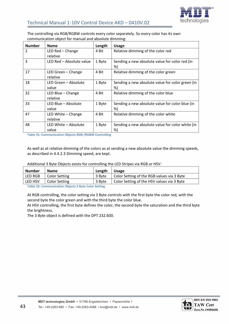
The controlling via RGB/RGBW controls every color separately. So every color has its own communication object for manual and absolute dimming:
Number Name Length Usage2 LED Red – Change
relative 4 Bit Relative dimming of the color red
3 LED Red – Absolute value 1 Byte Sending a new absolute value for color red (in %)
17 LED Green – Change relative
4 Bit Relative dimming of the color green
18 LED Green – Absolute value
1 Byte Sending a new absolute value for color green (in %)
32 LED Blue – Change relative
4 Bit Relative dimming of the color blue
33 LED Blue – Absolute value
1 Byte Sending a new absolute value for color blue (in %)
47 LED White – Change relative
4 Bit Relative dimming of the color white
48 LED White – Absolute value
1 Byte Sending a new absolute value for color white (in %)
Table 31: Communication Objects RGB‐/RGBW Controlling
As well as at relative dimming of the colors as at sending a new absolute value the dimming speeds, as described in 4.4.2.3 Dimming speed, are kept. Additional 3 Byte Objects exists for controlling the LED Stripes via RGB or HSV:
Number Name Length UsageLED RGB Color Setting 3 Byte Color Setting of the RGB values via 3 Byte
LED HSV Color Setting 3 Byte Color Setting of the HSV values via 3 Byte Table 32: Communication Objects 3 Byte Color Setting
At RGB controlling, the color setting via 3 Byte controls with the first byte the color red, with the second byte the color green and with the third byte the color blue. At HSV controlling, the first byte defines the color, the second byte the saturation and the third byte the brightness. The 3 Byte object is defined with the DPT 232.600.

Technical Manual 1‐10V Control Device AKD – 0410V.02
MDT technologies GmbH • 51766 Engelskirchen • Papiermühle 1 Tel.: +49-2263-880 • Fax: +49-2263-4588 • [email protected] • www.mdt.de 44
4.4.2LEDRGB/RGBWSettings All parameter in the chapter 4.4.2 refer to the menu LED RGB/RGBW Settings.
4.4.2.1WhiteBalance/Teach‐In By using the white balance, bad balanced RGB LEDs can be taught a clear white. If you take the color circle theory as basis, the 3 colors red, green and blue should generate the color white when all colors have the same intensity. This means for RGB Stripes, that when all colors are set to 100%, the color white should be reflected. This looks often different in reality. For getting a real white, the white balance is available. The white balance causes a proportional adaption off all color. So after setting all colors to 100% the adjusted clear white appears. So you can define your own white color as reference by using the white balance. Attention should be paid due to the fact that the white balance always reduce the maximum brightness of the LED Stripe, because dominating colors must be set to a lower value. For starting a white balance, this must be activated in the parameter settings:
Figure 22: White balance/Teach‐In
Thereupon the relevant communication object for controlling the white balance is shown:
Number Name Length Usage82 Teach‐In for white
balance 1 Bit Starting of the white balance
Table 33: Communication Object Teach‐In
The process of the Teach‐In is as follows: 1. Sending the value 0 to the Communication Object „Teach‐In for white balance“. Now the
colors Red, Green and Blue are set to 0%. At RGBW Stripes also the white color is set to 0%. 2. Now the colors Red, Green and Blue must be controlled to a clear white by sending absolute
or relative dimming commands. For example, if the color Blue dominates, this one must be controlled down until all colors are balanced.
3. Now the value 1 must be send to the Communication Object “Teach‐In for white balance” for stopping the Teach‐In process and saving the adjusted values. The proportionality is saved in the device. The three colors are set to 0% again. The White balance is completed.
The white balance is also kept after a new download or a bus power failure. For resetting the white balance: Sending a 0 to the object „Teach‐In for white balance“ and without sending any other commands a 1 to the same object.

Technical Manual 1‐10V Control Device AKD – 0410V.02
MDT technologies GmbH • 51766 Engelskirchen • Papiermühle 1 Tel.: +49-2263-880 • Fax: +49-2263-4588 • [email protected] • www.mdt.de 45
4.4.2.2Statevalues For visualization of the dimming process, different state objects can be shown. There as well single objects for the state as combined 3 Byte state objects. The following illustration shows how to activate the state objects:
Figure 23: State Objects
The Parameter “Output RGB/RGBW State” shows the objects for each color:
Number Name Length Usage5 LED Red‐Status Value 1 Byte Sending the State 0‐100% for the Color Red
20 LED Green‐Status Value 1 Byte Sending the State 0‐100% for the Color Green
35 LED Blue‐Status Value 1 Byte Sending the State 0‐100% for the Color Blue
50 LED White‐Status Value 1 Byte Sending the State 0‐100% for the Color White Table 34: Communication Objects RGB/RGBW individually
The parameter “Output HSV state” shows the state objects for Hue(H), Saturation(S) and Brightness(V):
Number Name Length Usage75 LED Hue(H) 1 Byte Sending of the state 0°‐360° for color in the
color circle
76 LED Saturation(S) 1 Byte Sending of the state 0‐100% for the saturation
77 LED Brightness(V) 1 Byte Sending of the state 0‐100% for the brightness Table 35: Communication objects HSV individually
The Parameter “Output 3 Byte State” shows additional combined 3 Byte State objects. The combined state objects at HSV sends on the first byte information about Hue, on the second byte about saturation and at the third byte about brightness. The object for RGB has the same structure ( Byte 1 = Red, Byte 2 = Green, Byte 3 = Blue). Also at RGBW Stripes, the object has only the length of 3 Bytes. The state of color white is not displayed in this object.
Number Name Length Usage73 Status RGB 3 Byte Sending of the 3 Byte State for RGB
74 Status HSV 3 Byte Sending of the 3 Byte State for HSV Table 36: Communication Objects 3 Byte State

Technical Manual 1‐10V Control Device AKD – 0410V.02
MDT technologies GmbH • 51766 Engelskirchen • Papiermühle 1 Tel.: +49-2263-880 • Fax: +49-2263-4588 • [email protected] • www.mdt.de 46
4.4.2.3Dimmingspeed For adjusting transitions and Soft‐Start/Stop, the dimming speeds can be adjusted:
Figure 24: Dimming Speeds
The parameters have the following effects:
Dim speed for relative dimming Defines the time for all relative dim processes related to relative dimming process of 100%. If a time of 10s is adjusted, the relative dimming from 0% to 100% and vice versa would last 10s. So the relative dimming from 0% to 50% would last 5s.
Dim speed for absolute dimming Defines the time for all absolute dimming processes related to an absolute dimming process of 100%. If a time of 10s is adjusted, the absolute dimming from 0% to 100% and vice versa would last 10s. So the absolute dimming from 0% to 50% would last 5s.
On Speed The On Speed realizes a Soft Start function. The On Speed refers only to the „hard“ switching via the object 63 “LED RGB/RGBW switch” or a Reset and not to the dimming up from 0%. At an On Speed of 2s, the LED stripes will be dimmed up to 100% in 2s at switching on.
Off Speed The On Speed realizes a Soft Stop function. The Off Speed refers only to the „hard“ switching via the object 63 “LED RGB/RGBW switch” and not to the dimming down to 0%. At an Off Speed of 2s, the LED stripes will be dimmed down to 0% in 2s at switching off.
Transition time at scenes The transition times between scenes defines the transition behavior between single scenes. The time refers as well to Bit Scenes (have a look at 4.4.4 LED RGB/RGBW Bit Scene) as to normal scenes (have a look at 4.4.5 LED RGB/RGBW Scene). It causes soft color transitions between two scenes. A time off 0s causes a hard switchover from one to the other scene.

Technical Manual 1‐10V Control Device AKD – 0410V.02
MDT technologies GmbH • 51766 Engelskirchen • Papiermühle 1 Tel.: +49-2263-880 • Fax: +49-2263-4588 • [email protected] • www.mdt.de 47
4.4.2.4BlockFunction The block function blocks the RGB/RGBW‐Stripe for further control and can call defined states. The following illustration shows the parameter for the blocking process:
Figure 25: Block function
The following table shows the available settings:
ETS‐text Dynamic range [default value]
comment
Behavior at Block value = 1
off
no change
switch to Hue
defines the behavior of the RGB/RGBW‐Stripe at activating the block function
Hue Red,… If the parameter “Behavior at Block” is set to “switch to Hue”, a predefined color can be called.
Behavior at Unblock value = o
off
no change
switch to Hue
defines the behavior of the RGB/RGBW‐Stripe at deactivating the block function
Hue Rot,… If the parameter “Behavior at Unblock” is set to “switch to Hue”, a predefined color can be called.
Table 37: Parameter block function
The following table shows the relevant communication object:
Number Name Length Usage81 Block 1 Bit blocks the RGB/RGBW stripe Table 38: Communication Object block function

Technical Manual 1‐10V Control Device AKD – 0410V.02
MDT technologies GmbH • 51766 Engelskirchen • Papiermühle 1 Tel.: +49-2263-880 • Fax: +49-2263-4588 • [email protected] • www.mdt.de 48
4.4.3LEDRGB/RGBWSequences Up to 5 sequences can be adjusted. These sequences can be set with predefined sequences or own sequences. The own sequences can be adjusted by using RGBW values or HSV values and can have up to 5 steps. The following illustration shows the activation of the sequences:
Figure 26: Activation of sequences
A submenu is shown for each activated sequence in which the sequences can be adjusted in detail. Furthermore a communication object, for starting and stopping, is shown for each sequence:
Number Name Length Usage83 Start sequence 1 1 Bit 1 = Start Sequence 1, 0 = Stop Sequence 1
84 Start sequence 2 1 Bit 1 = Start Sequence 2, 0 = Stop Sequence 2
85 Start sequence 3 1 Bit 1 = Start Sequence 3, 0 = Stop Sequence 3
86 Start sequence 4 1 Bit 1 = Start Sequence 4, 0 = Stop Sequence 4
87 Start sequence 5 1 Bit 1 = Start Sequence 5, 0 = Stop Sequence 5 Table 39: Communication Object Sequences
Applies to all sequences: If the sequence is adjusted and controlled in the RGB/RGBW behavior, the state values only the RGB/RGBW state values are transmitted. At sequences in HSV behavior, only HSV state values are transmitted. At the end of the dimming process all state values are transmitted.
4.4.3.1Predefinedsequences If the following parameter is selected, a number of predefined sequences are available:
Figure 27: Predefined sequences

Technical Manual 1‐10V Control Device AKD – 0410V.02
MDT technologies GmbH • 51766 Engelskirchen • Papiermühle 1 Tel.: +49-2263-880 • Fax: +49-2263-4588 • [email protected] • www.mdt.de 49
The following sequences can be selected:
Colorful The sequence “Colorful” runs through all colors of the color circle. At the initial step, the color circle will be run through clockwise. In the second step, the color circle will be run through contraclockwise. The starting point is the color red (0° or 360°°). The sequence is an endless loop, which means it will be swing back and forth in the color circle. The sequence has the following parameter: Saturation: Defines the saturation of the colors, which will be run through. Brightness: Defines the brightness of the colors, which will be run through. Transition time up to step 2: Defines the time, which is need for the run‐through clockwise. Transition time up to step 3: Defines the time, which is need for the run‐through contraclockwise
Warm Colors The sequence „Warm Colors“ contains 3 steps and runs through the colors Red‐>Orange ‐>Yellow, this means the first quarter of the color circle. This sequence is an endless loop. The sequence has the following parameter: Saturation: Defines the saturation of the colors, which will be run through. Brightness: Defines the brightness of the colors, which will be run through. Transition time up to step 2: Defines the time which is need for the transition from red to orange. Transition time up to step 3: Defines the time which is need for the transition from orange to yellow. Transition time up to step 4: Defines the time which is need for the transition from yellow back to red(starting point).
Cold Colors The sequence „Cold Colors“ contains of 4 steps and runs through the colors Aquamarine green‐>Turquoise‐>Mint‐>Blue. So the lower part of the color circle will be ran through. The sequence has the following parameter: Saturation: Defines the saturation of the colors, which will be run through. Brightness: Defines the brightness of the colors, which will be run through. Transition time up to step 2: Defines the time which is need for the transition from aquamarine green to turquoise. Transition time up to step 3: Defines the time which is need for the transition from turquoise to mint. Transition time up to step 4: Defines the time which is need for the transition from mint to blue.

Technical Manual 1‐10V Control Device AKD – 0410V.02
MDT technologies GmbH • 51766 Engelskirchen • Papiermühle 1 Tel.: +49-2263-880 • Fax: +49-2263-4588 • [email protected] • www.mdt.de 50
TV simulation/presence simulation The „TV simulation/presence simulation“ is an endless loop, which is built up completely with random values. That means as well the called colors as the transition times and the hold times are completely random. This sequence simulates the behavior of a TV.
Sunrise The sequence “sunrise” dims from an off state in the steps Red with low intensity‐>Red with higher intensity‐>Orange‐>Yellow. So the sunrise from the early red sky to the rise of the sun is simulated. The sequence has only one run‐through. The length of the “sunrise” can be adjusted via the parameters hold time and transition time.
Lounge random The sequence „Lounge random“ runs through the whole color circle from 0° to 360° with middle saturation. This sequence is an endless loop. The sequence has the following parameter: Brightness: Defines the brightness of the colors, which will be run through. Transition time[s]: Defines the transition time between the steps. Hold time in 100ms: Defines the hold time of the steps in multiple of 100ms.
Indicate HSV The sequence „Indicate HSV“ toggles between 2 free parameterizable colors. This sequence is an endless loop. The sequence has the following parameter: On‐ Values: Hue H: Defines the color which is called by switching on. Saturation S: Defines the saturation which is called by switching on. Brightness: V: Defines the brightness which is called by switching on. Period in 100ms: Defines the time how long a color is hold. The Off‐Values can be parameterized in the same way.

Technical Manual 1‐10V Control Device AKD – 0410V.02
MDT technologies GmbH • 51766 Engelskirchen • Papiermühle 1 Tel.: +49-2263-880 • Fax: +49-2263-4588 • [email protected] • www.mdt.de 51
4.4.3.2ManualSequencesRGBW/HSV There are two choices for the manual sequences available. On the one hand the manual sequences can be parameterized via RGB/RGBW and on the other hand via HSV. The available options are basically the same, only the presentation and the selection of the colors are different. The following basic settings can be done:
Figure 28: Basic settings manual sequences
The following table shows the available settings:
ETS‐text Dynamic range [default value]
comment
Switch sequence with fixed values
random values
defines whether the colors of the steps are fixed or random values are generated for each step
Number of parameter steps
1‐5 [1]
defines the number of steps of this sequence
Random transition time
not active
active
only at random values defines whether the time between two steps should be random or fixed
Endless loop not active
active
defines whether the sequence shall run in an endless loop or not
Number of execution
1‐255 [1]
is only shown if no endless loop is active Parameter defines the number of executions
Continuation sequence
not active
1
2
3
4
5
is only shown if no endless loop is active Parameter defines the sequence which shall be called after this sequence
Table 40: Basic settings manual sequence

Technical Manual 1‐10V Control Device AKD – 0410V.02
MDT technologies GmbH • 51766 Engelskirchen • Papiermühle 1 Tel.: +49-2263-880 • Fax: +49-2263-4588 • [email protected] • www.mdt.de 52
Sequence with fixed values: When the sequence is controlled with fixed values, the fixed values which are called can be adjusted. The following figure shows the available settings for fixed values with HSV‐Control:
Figure 29: Manual sequence with fixed values
As shown at the upper figure, for every step a predefined color can be called. Additional the saturation and the brightness can be called at the HSV‐Control. The hold time defines how long a step is hold, which means the sequence stays for the adjusted time at this step. The transition time defines the time how long the dimming takes from one step to the next one. Furthermore it is possible to select predefined colors or adjust them by your own. The following parameter switches between predefined colors and manual configuration:
Figure 30: Manual Sequence RGB/RGBW Hue setting

Technical Manual 1‐10V Control Device AKD – 0410V.02
MDT technologies GmbH • 51766 Engelskirchen • Papiermühle 1 Tel.: +49-2263-880 • Fax: +49-2263-4588 • [email protected] • www.mdt.de 53
Sequence with random values: If the sequence is switched with random values, the colors will be generated randomly of the device. The random values can be restricted. The following illustration shows the sequence with random values at RGB –Control:
Figure 31: Manual sequence with random values
As seen on the upper picture, every color can be restricted. These settings are in the same way available for HSV‐Control. In this setting the values for H, S and V can be restricted. The hold time defines how long a step is hold, which means the sequence stays for the adjusted time at this step. Furthermore the transition time can be switched between random or fixed values:
Figure 32: Transition time
A random transition time can be restricted from zero to fixed maximum value. So the random time has an upper maximum. The following parameter is shown for a random transition time:
Figure 33: Random transition time
If the parameter “Random transition time” is switched to not active, a fixed value for the transition time must be adjusted. The transition time defines the time of the dimming process between two steps.

Technical Manual 1‐10V Control Device AKD – 0410V.02
MDT technologies GmbH • 51766 Engelskirchen • Papiermühle 1 Tel.: +49-2263-880 • Fax: +49-2263-4588 • [email protected] • www.mdt.de 54
Number of executions: The number of executions can be defined with the following setting:
Figure 34: Manual sequence ‐ Number of Executions
If the sequence is defined as endless loop, the sequence runs as long it will be stopped by sending a stop command to its communication object. Further settings for the number of executions are not available for this setting. If the endless loop is not active, the number of executions can be defined. Furthermore a continuation sequence can be called. For example, sequence 1 can call sequence2, which calls sequence 3, which calls again sequence 1. So an endless loop with 3 sequences is performed. Furthermore this parameter can be used for extending a sequence with 5 more steps per continuation sequence.

Technical Manual 1‐10V Control Device AKD – 0410V.02
MDT technologies GmbH • 51766 Engelskirchen • Papiermühle 1 Tel.: +49-2263-880 • Fax: +49-2263-4588 • [email protected] • www.mdt.de 55
4.4.4LEDRGB/RGBWBitScenes Two different Bit scenes can be adjusted. The Bit scene‐function enables calling absolute values with a one Bit communication object. As well for the value 1 as for the value 0 colors can be adjusted, which can be selected via RGB/RGBW or HSV. The following illustration shows the parameter for the Control mode of Bit scene 1:
Figure 35: Bit scene ‐ Control Mode
The color selection can be done with predefined values of by manual control:
Figure 36: Hue setting with predefined colors
At the setting “predefined color”, for each value and each Bit scene individual settings are available. The following settings are available for HSV‐Control:
ETS‐text Dynamic range [default value]
comment
Hue for Bit value 0/1 Red, Orange, Yellow, … [Red]
Adjustment of the color, which should be called
Saturation S for Bit value 0/1
0‐100% [100%]
Adjustment of the saturation, which should be called
Brightness H for Bit value 0/1
0‐100% [100%]
Adjustment of the brightness, which should be called
Table 41: Bit scenes‐HSV with predefined values
The following settings are available for RGB/RGBW‐Control:
ETS‐text Dynamic range [default value]
comment
Hue for Bit value 0/1 Red, Orange, Yellow, … [Red]
Adjustment of the color, which should be called
Table 42: Bit scenes‐RGB with predefined values

Technical Manual 1‐10V Control Device AKD – 0410V.02
MDT technologies GmbH • 51766 Engelskirchen • Papiermühle 1 Tel.: +49-2263-880 • Fax: +49-2263-4588 • [email protected] • www.mdt.de 56
At the setting “manual setting”, for each value and each Bit scene individual settings are available. The following settings are available for HSV‐Control:
ETS‐text Dynamic range [default value]
comment
Hue for Bit value 0/1 0°‐360° [Red H=0°]
Adjustment of the angle which shall be called in the color circle
Saturation S for Bit value 0/1
0‐100% [100%]
Adjustment of the saturation which shall be called
Brightness V for Bit value 0/1
0‐100% [100%]
Adjustment of the brightness which shall be called
Table 43: Bit scenes‐HSV Control with manual setting
The following settings are available for RGB/RGBW‐Control:
ETS‐text Dynamic range [default value]
comment
Hue Red for Bit value 0/1 0%‐100% [0%]
Adjustment of the absolute value for the red channel
Hue green for Bit value 0/1 0%‐100% [0%]
Adjustment of the absolute value for the red channel
Hue blue for Bit value 0/1 0%‐100% [0%]
Adjustment of the absolute value for the red channel
Hue white for Bit value 0/1 0%‐100% [0%]
Adjustment of the absolute value for the red channel
Table 44: Bit scenes‐RGB/RGBW Control with manual setting
The following communication objects call the Bit‐Scenes:
Number Name Length Usage79 Bit Scene 1 1 Bit Calling Bit Scene 1
80 Bit Scene 2 1 Bit Calling Bit Scene 2 Table 45: Communication objects Bit scenes
The communication objects for the Bit scenes are only shown if the bit scenes are activated. The transition time for the scenes can be defined as described in 4.4.2.3 Dimming speed.

Technical Manual 1‐10V Control Device AKD – 0410V.02
MDT technologies GmbH • 51766 Engelskirchen • Papiermühle 1 Tel.: +49-2263-880 • Fax: +49-2263-4588 • [email protected] • www.mdt.de 57
4.4.5LEDRGB/RGBWScenes Up to 8 scenes can be programmed, which can be assigned one of the 64 available scene numbers. The following illustration shows the available settings for submenu LED RGBW scenes:
Figure 37: LED RGB/RGBW scenes
Technical Manual 1‐10V Control Device AKD – 0410V.02
MDT technologies GmbH • 51766 Engelskirchen • Papiermühle 1 Tel.: +49-2263-880 • Fax: +49-2263-4588 • [email protected] • www.mdt.de 58
The following table shows the available settings for an activated scene function:
ETS‐text Dynamic range [default value]
comment
Save scenes disabled
enabled
defines if the memory function shall be enabled for the scenes
Mode RGB/RGBW
HSV
Adjustment of the Control Mode
Scene Nr. A‐[H] not active
active
Activation/Deactivation of the scenes
Scene number 1‐64 [1]
defines the value for calling this scene
Hue setting with predefined color
manual setting
Adjustment how the color for this scene shall be set
Table 46: Scene function
According to the adjusted mode and the selection of the hue setting, the color which shall be called, can be adjusted in different ways. For the HSV‐Mode with predefined colors, the following settings are available:
ETS‐text Dynamic range [default value]
comment
Hue Rot, Orange, Gelb, … [Rot]
Adjustment of the color
Saturation S 0‐100% [100%]
Adjustment of the saturation
Brightness V 0‐100% [100%]
Adjustment of the brightness
Table 47: Scenes‐ HSV control with predefined colors
For the RGB/RGBW‐Mode with predefined colors, the following settings are available:
ETS‐text Dynamic range [default value]
comment
Hue Rot, Orange, Gelb, … [Rot]
Adjustment of the color
Table 48: Scenes‐RGB control with predefined colors
Technical Manual 1‐10V Control Device AKD – 0410V.02
MDT technologies GmbH • 51766 Engelskirchen • Papiermühle 1 Tel.: +49-2263-880 • Fax: +49-2263-4588 • [email protected] • www.mdt.de 59
For the HSV‐Mode with manual setting, the following settings are available:
ETS‐text Dynamic range [default value]
comment
Hue 0°‐360° [Rot = 0°]
Adjustment of the angle in the color circle
Saturation S 0‐100% [100%]
Adjustment of the saturation
Brightness V 0‐100% [100%]
Adjustment of the brightness
Table 49: Scenes‐HSV control with manual setting
For the RGB/RGBW‐Mode with manual setting, the following settings are available:
ETS‐text Dynamic range [default value]
comment
Hue Red 0%‐100% [0%]
Adjustment of the absolute value for the red channel
Hue Green 0%‐100% [0%]
Adjustment of the absolute value for the green channel
Hue Blue 0%‐100% [0%]
Adjustment of the absolute value for the blue channel
Hue White 0%‐100% [0%]
Adjustment of the absolute value for the white channel
Table 50: Scenes‐RGB Control with manual setting
The following communication object calls the adjusted scenes:
Number Name Length Usage78 Scene 1 Byte Calling the scenes Table 51: Communication object scene
The communication object for the scenes is only shown if the scenes are active. The transition time of the scenes can be adjusted as described in 4.4.2.3 Dimming speed.

Technical Manual 1‐10V Control Device AKD – 0410V.02
MDT technologies GmbH • 51766 Engelskirchen • Papiermühle 1 Tel.: +49-2263-880 • Fax: +49-2263-4588 • [email protected] • www.mdt.de 60
For calling a scene or saving a scene with a new value, the corresponding code must be sent to the communication object for the scenes:
Scene Calling Saving Hex. Dec. Hex. Dec.
1 0x00 0 0x80 128
2 0x01 1 0x81 129
3 0x02 2 0x82 130
4 0x03 3 0x83 131
5 0x04 4 0x84 132
6 0x05 5 0x85 133
7 0x06 6 0x86 134
8 0x07 7 0x87 135
9 0x08 8 0x88 136
10 0x09 9 0x89 137
11 0x0A 10 0x8A 138
12 0x0B 11 0x8B 139
13 0x0C 12 0x8C 140
14 0x0D 13 0x8D 141
15 0x0E 14 0x8E 142
16 0x0F 15 0x8F 143
17 0x10 16 0x90 144
18 0x11 17 0x91 145
19 0x12 18 0x92 146
20 0x13 19 0x93 147
21 0x14 20 0x94 148
22 0x15 21 0x95 149
23 0x16 22 0x96 150
24 0x17 23 0x97 151
25 0x18 24 0x98 152
26 0x19 25 0x99 153
27 0x1A 26 0x9A 154
28 0x1B 27 0x9B 155
29 0x1C 28 0x9C 156
30 0x1D 29 0x9D 157
31 0x1E 30 0x9E 158
32 0x1F 31 0x9F 159 Table 52: Calling and saving scenes

Technical Manual 1‐10V Control Device AKD – 0410V.02
MDT technologies GmbH • 51766 Engelskirchen • Papiermühle 1 Tel.: +49-2263-880 • Fax: +49-2263-4588 • [email protected] • www.mdt.de 61
5Index
5.1ListofIllustrations Figure 1: Structure Hardware .................................................................................................................. 4 Figure 2: Function Selection 1‐10V Dimmer............................................................................................ 7 Figure 3: Circuit Diagram 1‐10V ECG ....................................................................................................... 7 Figure 4: Channel activation .................................................................................................................. 13 Figure 5: On‐/Off‐delay ......................................................................................................................... 15 Figure 6: Staircase light activation ........................................................................................................ 16 Figure 7: Staircase light ......................................................................................................................... 17 Figure 8: Starting behavior .................................................................................................................... 19 Figure 9: Dimming area ......................................................................................................................... 20 Figure 10: Specific dimming settings ..................................................................................................... 21 Figure 11: Central objects ..................................................................................................................... 23 Figure 12: Scene function ...................................................................................................................... 24 Figure 13: Submenu scene .................................................................................................................... 25 Figure 14: Parameter Automatic function............................................................................................. 28 Figure 15: Submenu automatic function ............................................................................................... 29 Figure 16: Additional functions ............................................................................................................. 30 Figure 17: Function Selection Dimming RGB LED .................................................................................. 33 Figure 18: Function Selection Dimming RGBW LED .............................................................................. 33 Figure 19: Circuit Diagram RGB‐/RGBW‐Stripes .................................................................................... 33 Figure 20: Color Circle ........................................................................................................................... 41 Figure 21: Way of Controlling ................................................................................................................ 42 Figure 22: White balance/Teach‐In ....................................................................................................... 44 Figure 23: State Objects ........................................................................................................................ 45 Figure 24: Dimming Speeds ................................................................................................................... 46 Figure 25: Block function ....................................................................................................................... 47 Figure 26: Activation of sequences ....................................................................................................... 48 Figure 27: Predefined sequences .......................................................................................................... 48 Figure 28: Basic settings manual sequences ......................................................................................... 51 Figure 29: Manual sequence with fixed values ..................................................................................... 52 Figure 30: Manual Sequence RGB/RGBW Hue setting .......................................................................... 52 Figure 31: Manual sequence with random values ................................................................................ 53 Figure 32: Transition time ..................................................................................................................... 53 Figure 33: Random transition time ....................................................................................................... 53 Figure 34: Manual sequence ‐ Number of Executions .......................................................................... 54 Figure 35: Bit scene ‐ Control Mode ...................................................................................................... 55 Figure 36: Hue setting with predefined colors ...................................................................................... 55 Figure 37: LED RGB/RGBW scenes ........................................................................................................ 57
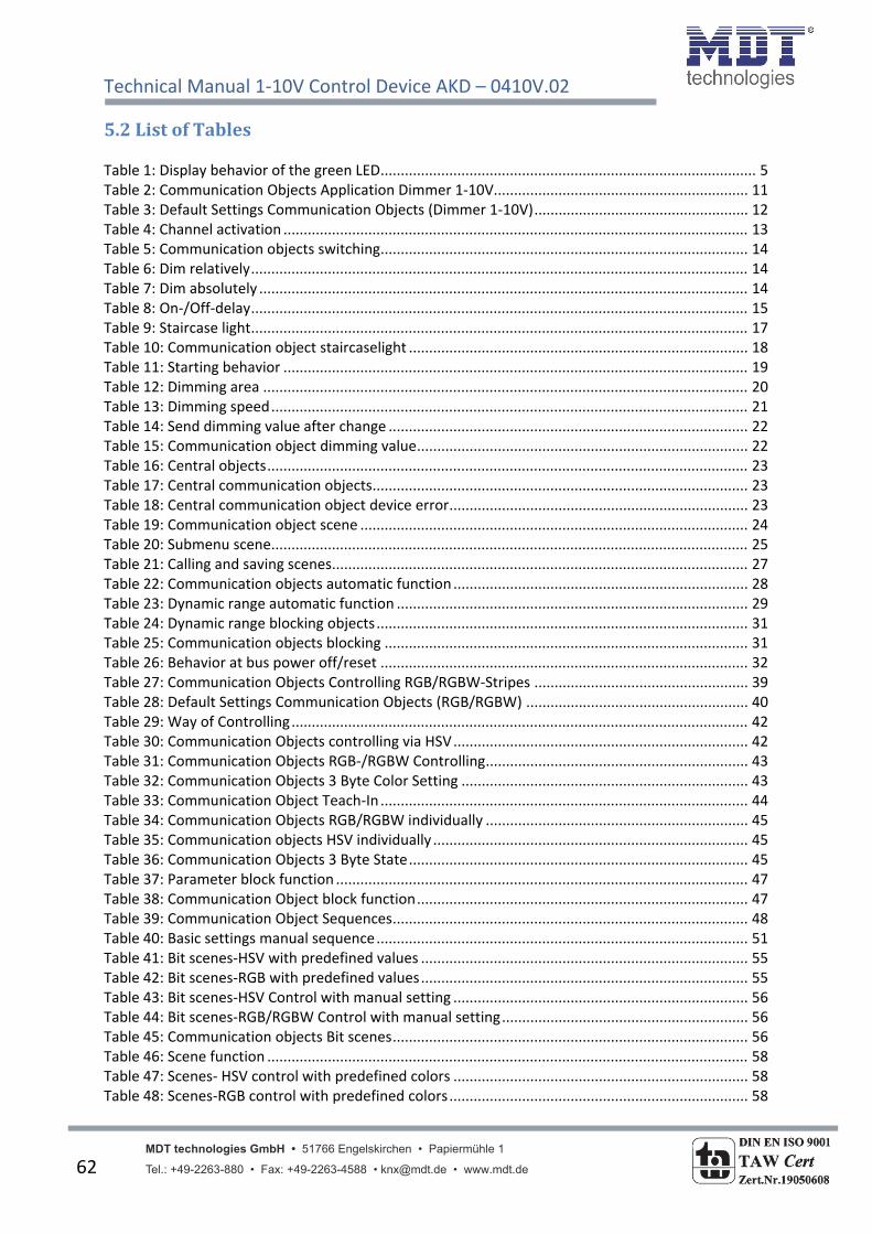
Technical Manual 1‐10V Control Device AKD – 0410V.02
MDT technologies GmbH • 51766 Engelskirchen • Papiermühle 1 Tel.: +49-2263-880 • Fax: +49-2263-4588 • [email protected] • www.mdt.de 62
5.2ListofTables Table 1: Display behavior of the green LED ............................................................................................. 5 Table 2: Communication Objects Application Dimmer 1‐10V............................................................... 11 Table 3: Default Settings Communication Objects (Dimmer 1‐10V) ..................................................... 12 Table 4: Channel activation ................................................................................................................... 13 Table 5: Communication objects switching ........................................................................................... 14 Table 6: Dim relatively ........................................................................................................................... 14 Table 7: Dim absolutely ......................................................................................................................... 14 Table 8: On‐/Off‐delay ........................................................................................................................... 15 Table 9: Staircase light ........................................................................................................................... 17 Table 10: Communication object staircaselight .................................................................................... 18 Table 11: Starting behavior ................................................................................................................... 19 Table 12: Dimming area ........................................................................................................................ 20 Table 13: Dimming speed ...................................................................................................................... 21 Table 14: Send dimming value after change ......................................................................................... 22 Table 15: Communication object dimming value .................................................................................. 22 Table 16: Central objects ....................................................................................................................... 23 Table 17: Central communication objects ............................................................................................. 23 Table 18: Central communication object device error .......................................................................... 23 Table 19: Communication object scene ................................................................................................ 24 Table 20: Submenu scene...................................................................................................................... 25 Table 21: Calling and saving scenes ....................................................................................................... 27 Table 22: Communication objects automatic function ......................................................................... 28 Table 23: Dynamic range automatic function ....................................................................................... 29 Table 24: Dynamic range blocking objects ............................................................................................ 31 Table 25: Communication objects blocking .......................................................................................... 31 Table 26: Behavior at bus power off/reset ........................................................................................... 32 Table 27: Communication Objects Controlling RGB/RGBW‐Stripes ..................................................... 39 Table 28: Default Settings Communication Objects (RGB/RGBW) ....................................................... 40 Table 29: Way of Controlling ................................................................................................................. 42 Table 30: Communication Objects controlling via HSV ......................................................................... 42 Table 31: Communication Objects RGB‐/RGBW Controlling ................................................................. 43 Table 32: Communication Objects 3 Byte Color Setting ....................................................................... 43 Table 33: Communication Object Teach‐In ........................................................................................... 44 Table 34: Communication Objects RGB/RGBW individually ................................................................. 45 Table 35: Communication objects HSV individually .............................................................................. 45 Table 36: Communication Objects 3 Byte State .................................................................................... 45 Table 37: Parameter block function ...................................................................................................... 47 Table 38: Communication Object block function .................................................................................. 47 Table 39: Communication Object Sequences ........................................................................................ 48 Table 40: Basic settings manual sequence ............................................................................................ 51 Table 41: Bit scenes‐HSV with predefined values ................................................................................. 55 Table 42: Bit scenes‐RGB with predefined values ................................................................................. 55 Table 43: Bit scenes‐HSV Control with manual setting ......................................................................... 56 Table 44: Bit scenes‐RGB/RGBW Control with manual setting ............................................................. 56 Table 45: Communication objects Bit scenes ........................................................................................ 56 Table 46: Scene function ....................................................................................................................... 58 Table 47: Scenes‐ HSV control with predefined colors ......................................................................... 58 Table 48: Scenes‐RGB control with predefined colors .......................................................................... 58

Technical Manual 1‐10V Control Device AKD – 0410V.02
MDT technologies GmbH • 51766 Engelskirchen • Papiermühle 1 Tel.: +49-2263-880 • Fax: +49-2263-4588 • [email protected] • www.mdt.de 63
Table 49: Scenes‐HSV control with manual setting ............................................................................... 59 Table 50: Scenes‐RGB Control with manual setting .............................................................................. 59 Table 51: Communication object scene ................................................................................................ 59 Table 52: Calling and saving scenes ....................................................................................................... 60

Technical Manual 1‐10V Control Device AKD – 0410V.02
MDT technologies GmbH • 51766 Engelskirchen • Papiermühle 1 Tel.: +49-2263-880 • Fax: +49-2263-4588 • [email protected] • www.mdt.de 64
6Attachment
6.1Statutoryrequirements
The above‐described devices must not be used with devices, which serve directly or indirectly the
purpose of human, health‐ or lifesaving. Further the devices must not be used if their usage can
occur danger for humans, animals or material assets.
Do not let the packaging lying around careless, plastic foil/ ‐bags etc. can be a dangerous toy for kids.
6.2Routinedisposal
Do not throw the waste equipment in the household rubbish. The device contains electrical devices,
which must be disposed as electronic scrap. The casing contains of recyclable synthetic material.
6.3Assemblage
Risk for life of electrical power!
All activities on the device should only be done by an electrical specialist. The county specific
regulations and the applicable EIB‐directives have to be observed.

AKD-0401.01
AKD-0201.01 AKD-0410V.02
MDT Dimming Actuator 1/2/4-fold, MDRC
Version
AKD-0201.01 Dimming Actuator 2-fold 4SU MDRC, 230VAC, 250W
AKD-0401.01 Dimming Actuator 4-fold 8SU MDRC, 230VAC, 250W
AKD-0103.01 Dimming Actuator 1-fold 4SU MDRC, 230VAC, 600W
AKD-0203.01 Dimming Actuator 2-fold 8SU MDRC, 230VAC, 600W
AKD-0410V.02 Control Device 4-fold 4TE MDRC, 1-10V, With RGBW functionality
The MDT Dimming Actuator receives KNX/EIB telegrams and dimms/switches up to 4 independent electrical loads. Each output can be operated manually via a push button.
The outputs are for switching and dimming incandescent lamps, HV halogen lamps, LV halogen lamps (with conventionel or suitable electronic transformers), dimmable energy saving lamps and LED lightning. Leading or trailing edge principle can be chosen. The device has an integrated shortcircuit and excess temperature protection plus softstart function (Dimming speed adjustable) to increase lamp life time.
Programmable performance after mains voltage failure, bus voltage failure or return.
The 1-10V MDT Control Device has embedded switching relays for 30 ECG/30W, 20 ECG/58W, 15 ECG/2x36W or 10ECG/2x58W. Each channel offers control voltage up to 30 electronic transformers (ECG).
The MDT Dimming Actuator is a modular installation device for fixed installation in dry rooms. It fits on DIN 35mm rails in power distribution boards or closed compact boxes.
For project design and commissioning of the MDT Dimming Actuator it is recommended to use the ETS3f/ETS4 or later. Please download the application software at www.mdt.de/Downloads.html
• Production in Germany, certified according to ISO 9001• 2W minimum load for LED lightning possible• Push Button and LED indicator for each channel• For dimming and switching incandescent lamps, HV halogen lamps, LV halogen lamps ( with conventional or suitable electronic transformers), dimmable energy saving lamps and LED lightning • Dimming operation in leading or trailing edge • Characteristic dimming curve selectable• Short circuit and temperature protection with alarm, softstart• Time functions (swich-on/switch-off delay, staircase light function)• Each contact has an own supply phase/neutral conductor• Modular installation device for DIN 35mm rails• Integrated bus coupling unit • 3 years warranty
MDT Dimming Actuator
MDT technologies GmbH • 51766 Engelskirchen • Papiermühle 1
Tel.: + 49 - 2263 - 880 • Fax: + 49 - 2263 - 4588 • [email protected] • www.mdt.de
Stand: 0314
DIN EN ISO 9001
TAW Cert Zert.Nr.1905606
N

MDT Dimming Actuator
Technical Data
AKD-0201.01AKD-0401.01
AKD-0103.01AKD-0203.01
Technical Data
AKD-0410V.02
Number of outputs 2/4 1/2 Number of outputs 4
Switching voltage outputs 230VAC/50Hz 230VAC/50Hz Switching voltage outputs 230VAC/50Hz
Max. fuse per channel 10A 10A Max. fuse per channel 16A
Switching voltage control outputs 1-10V
Maximum lamp load per channel* 250W 600W Maximum number of ECG 30
Minimum lamp load per channel 2W**/12W 2W**/20W Maximum current switching relais 16A/100uF
Permitted wire gauge Permitted wire gauge
Screw terminal0,5 - 4,0mm² solid core
0,5 - 2,5mm² finely stranded Screw terminal0,5 - 4,0mm² solid core 0,5 - 2,5mm² finely str.
KNX busconnection terminal 0,8mm Ø, solid core KNX busconnection terminal 0,8mm Ø, solid core
Power supply KNX bus KNX bus Power supply KNX bus
Power consumption KNX bus typ.*** < 0,3W < 0,3W Power consumption*** < 0,3W
Power dissipation no load**** < 0,5W < 0,5W
Power dissipation nominal load**** < 4W < 8W
Operation temperature range 0 to + 45°C 0 to + 45°C Operation temperature range 0 to + 45°C
Enclosure IP 20 IP 20 Enclosure IP 20
Dimensions MDRC (Space Units) 4/8SU 4/8SU Dimensions MDRC (Space Units) 4SU
* Maximum load for dimmable energy saving lamps is 80W (AKD-xx01.01) or 200W (AKD-xx03.01) Maximum load for dimmable LED lamps is, depending on the LED lamp manufacturer, 25-80W (AKD-xx01.01) or 60-200W (AKD-xx03.01) ** Minimum load for dimmable LED lamps is 2W, depending on the LED lamp manufacturer. Correct function of the LED lamps has to be checked before installation.
*** Power consumption from KNX Bus **** Maximum power dissipation for each channel
Note: Dimming Actuators AKD have separate Power supply terminals for each channel. The channel outputs can not be bridged.
Examplary circuit diagram AKD-0401.01
Important assembly note:- Conventionel transformers must be fused on primary side with adequate fuse according to the size of the transformator.- The AC power line has to be connected separately to each Dimming Actuator. Connecting of several devices is not allowed.- The neutral line has to be connected separately to each channel. Do not bypass directly on the screw terminals.
MDT technologies GmbH • 51766 Engelskirchen • Papiermühle 1
Tel.: + 49 - 2263 - 880 • Fax: + 49 - 2263 - 4588 • [email protected] • www.mdt.de
Stand: 0314
DIN EN ISO 9001
TAW Cert Zert.Nr.1905606
N