Embed Size (px)
Citation preview
VANNER Incorporated Owner’s Manual
MBVCE OWNER’S MANUAL
1
MBVCE
Stand-Alone Battery Monitor
VANNER Incorporated Owner's Manual
MBVCE OWNER’S MANUAL
2
Table of Contents
Introduction ................................................................................................ 3
Specifications ............................................................................................. 4
Dimensional Specifications......................................................................... 4
Theory of Operation ................................................................................... 5
Configurable Settings ................................................................................. 7
Installation Instructions ............................................................................... 8
MBVCE Definitions and Functionality ......................................................... 9
System Wiring .......................................................................................... 10
Typical Application/Wiring ........................................................................ 11
Troubleshooting ....................................................................................... 15
Vanner Repair Service ............................................................................. 17
VANNER Incorporated Owner's Manual
MBVCE OWNER’S MANUAL
3
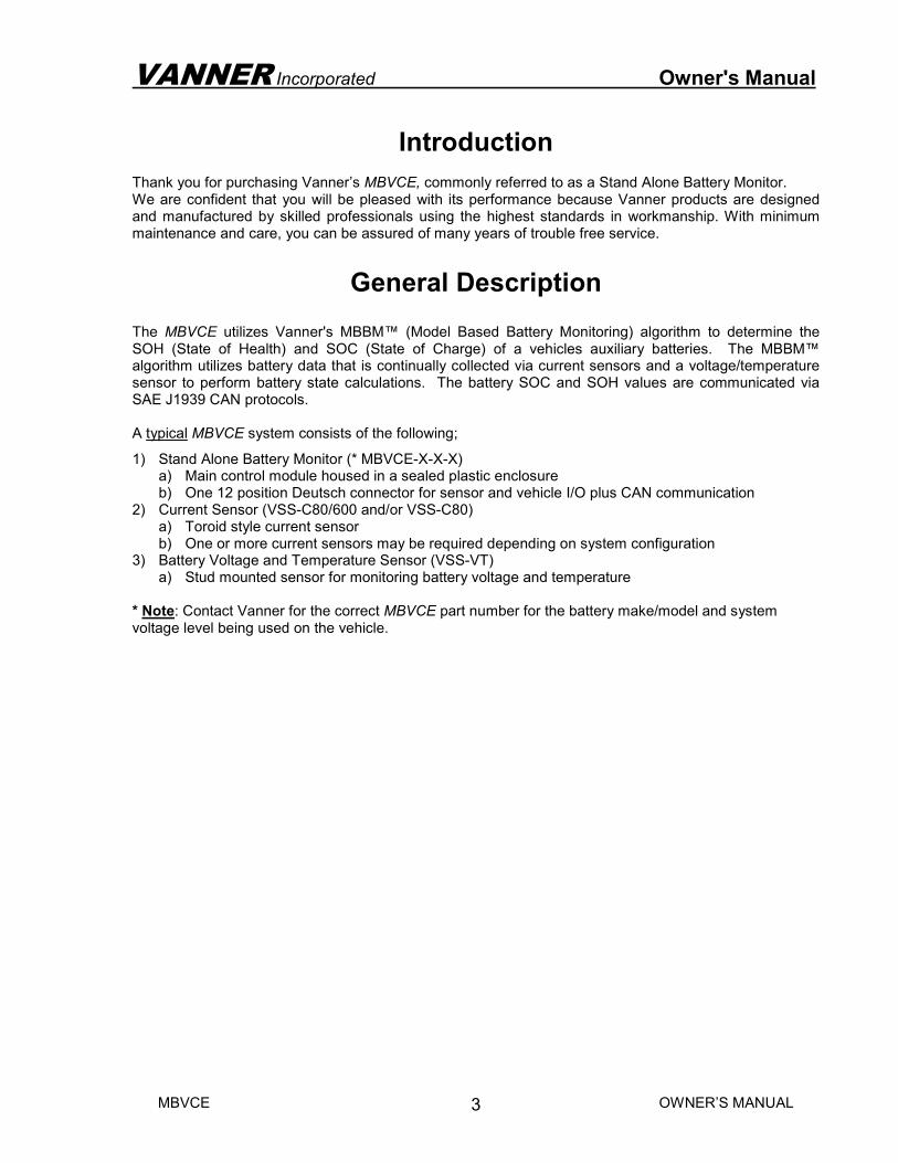
Introduction Thank you for purchasing Vanner’s MBVCE, commonly referred to as a Stand Alone Battery Monitor. We are confident that you will be pleased with its performance because Vanner products are designed and manufactured by skilled professionals using the highest standards in workmanship. With minimum maintenance and care, you can be assured of many years of trouble free service.
General Description The MBVCE utilizes Vanner's MBBM™ (Model Based Battery Monitoring) algorithm to determine the SOH (State of Health) and SOC (State of Charge) of a vehicles auxiliary batteries. The MBBM™ algorithm utilizes battery data that is continually collected via current sensors and a voltage/temperature sensor to perform battery state calculations. The battery SOC and SOH values are communicated via SAE J1939 CAN protocols. A typical MBVCE system consists of the following;
1) Stand Alone Battery Monitor (* MBVCE-X-X-X) a) Main control module housed in a sealed plastic enclosure b) One 12 position Deutsch connector for sensor and vehicle I/O plus CAN communication
2) Current Sensor (VSS-C80/600 and/or VSS-C80) a) Toroid style current sensor b) One or more current sensors may be required depending on system configuration
3) Battery Voltage and Temperature Sensor (VSS-VT) a) Stud mounted sensor for monitoring battery voltage and temperature
* Note: Contact Vanner for the correct MBVCE part number for the battery make/model and system voltage level being used on the vehicle.
VANNER Incorporated Owner's Manual
MBVCE OWNER’S MANUAL
4
Specifications
MBVCE Stand Alone Battery Monitor
Model Number MBVCE
Input Voltage Range (VDC) 9.5 – 32
(Reverse Polarity Protected)
Output Voltage Range (VDC) 9.5 - 32
Standby Current (Milliamps) <30mA @ 24V, <60mA @ 12V
Operating Temp. -40°C to +60°C (-40°F to 140°F)
Storage Temp. -40°C to +85°C (-40°F to 185°F)
Serviceable Internal components to be serviced by Vanner personnel only.
Environmental Considerations Sealed plastic enclosure (Ultem - Natural) provides protection against salt, fungus, dust, water, fuel vapors and all fluids associated with commercial
and off-highway vehicle operations. IP67 Rated.
Mounting Location Mount on a flat surface.
Location should be protected from battery acid and gases.
Weight (lbs.) 1.25 lbs (.6 kG)
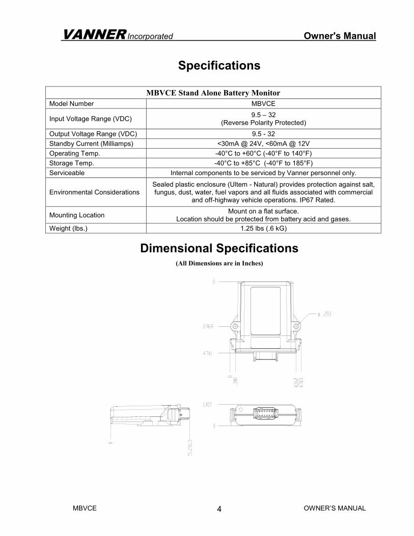
Dimensional Specifications (All Dimensions are in Inches)
VANNER Incorporated OWNER’S MANUAL
MBVCE OWNER’S MANUAL
5
Theory of Operation
Battery Monitoring
The primary function of the MBVCE is to monitor the auxiliary batteries on a vehicle. The monitoring algorithm analyzes battery voltage, current, and temperature inputs, and calculates the SOC (State of Charge), SOH (State of Health), SOCach (Achievable State of Charge based on SOH and temperature of battery), U (Estimated Time to Run), and Up (Estimated Time to Run adjusted by SOH and temperature of battery) of the battery. In order for the MBVCE system to accurately calculate/estimate the SOC, SOH and SOCach, of the battery/batteries, there are three critical settings that need to be configured. The settings are as follows;
• Battery Type: This is defined by the make and model of the battery being used.
• Nb: This is the number of batteries that are connected in parallel
• Voltage Level: The voltage level setting defines whether it is a 12V single, 24V single or 24/12V dual battery arrangement
An MBVCE is ordered from the factory with the customer defined battery profile, Nb and voltage level settings pre-loaded. Please contact Vanner to ensure you specify the appropriate model number for the application. Alternatively, the appropriate battery profile, Nb and voltage level settings can be loaded during system installation via Vanner's CAN interface software, commonly referred to as Dashboard. A laptop provisioned with the Dashboard software allows the user to enter battery parameters and customize configuration settings and validate the system works via CAN bus. Please reference the Vanner CAN Interface User Manual which is available at http://www.vanner.com.
Battery Type
The characteristics of a battery differ by type, manufacturer, and capacity. It is critical to use the appropriate battery profile for accurate battery monitoring.
Nb
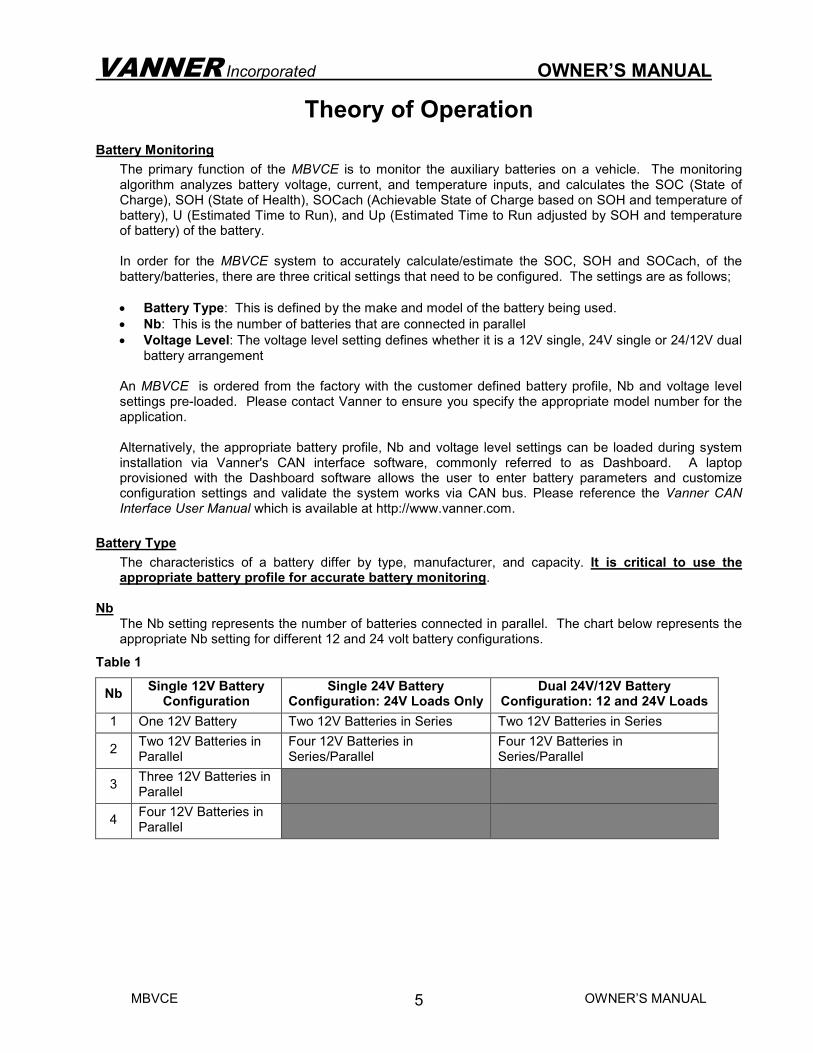
The Nb setting represents the number of batteries connected in parallel. The chart below represents the appropriate Nb setting for different 12 and 24 volt battery configurations.
Table 1
Nb Single 12V Battery Configuration
Single 24V Battery Configuration: 24V Loads Only
Dual 24V/12V Battery Configuration: 12 and 24V Loads
1 One 12V Battery Two 12V Batteries in Series Two 12V Batteries in Series
2 Two 12V Batteries in Parallel
Four 12V Batteries in Series/Parallel
Four 12V Batteries in Series/Parallel
3 Three 12V Batteries in Parallel
4 Four 12V Batteries in Parallel
VANNER Incorporated OWNER’S MANUAL
MBVCE OWNER’S MANUAL
6
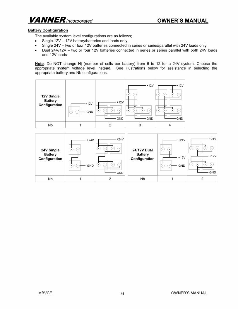
Battery Configuration
The available system level configurations are as follows;
• Single 12V – 12V battery/batteries and loads only
• Single 24V – two or four 12V batteries connected in series or series/parallel with 24V loads only
• Dual 24V/12V – two or four 12V batteries connected in series or series parallel with both 24V loads and 12V loads
Note: Do NOT change Nj (number of cells per battery) from 6 to 12 for a 24V system. Choose the appropriate system voltage level instead. See illustrations below for assistance in selecting the appropriate battery and Nb configurations.
1
+12V
GND+ -
2
+12V
GND
+ - + -
3
+12V
GND
+ -+ -
+ -
4
+12V
GND
+ -+ -
+ - + -
Nb
12V Single
Battery
Configuration
+24V
GND
+ -
+ -
1 2
+24V
GND
+ -
+ -
+ -
+ -
Nb
24V Single
Battery
Configuration
Nb
24/12V Dual
Battery
Configuration
+24V
+12V
GND
+ -
+ -
1 2
+24V
+12V
GND
+ -
+ -
+ -
+ -
VANNER Incorporated OWNER’S MANUAL
MBVCE OWNER’S MANUAL
7
Configurable Settings There are multiple settings in the MBVCE that are user configurable, via Vanner's CAN interface software, to maximize system efficiency. Once the configurable settings are defined, they can be exported to a file for importing into other units. This ensures consistency of the settings from one unit to the next. Please reference the Vanner CAN Interface User Manual which is available at www.vanner.com.
Engine Controls
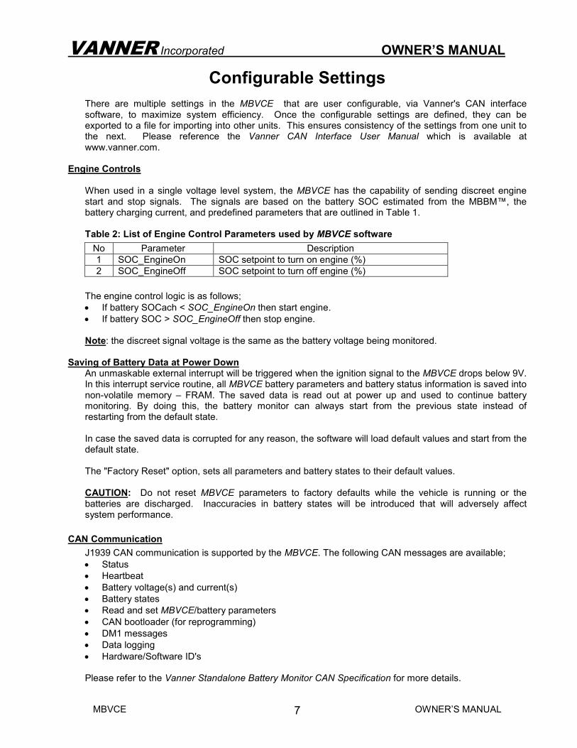
When used in a single voltage level system, the MBVCE has the capability of sending discreet engine start and stop signals. The signals are based on the battery SOC estimated from the MBBM™, the battery charging current, and predefined parameters that are outlined in Table 1. Table 2: List of Engine Control Parameters used by MBVCE software
No Parameter Description
1 SOC_EngineOn SOC setpoint to turn on engine (%)
2 SOC_EngineOff SOC setpoint to turn off engine (%)
The engine control logic is as follows;
• If battery SOCach < SOC_EngineOn then start engine.
• If battery SOC > SOC_EngineOff then stop engine. Note: the discreet signal voltage is the same as the battery voltage being monitored.
Saving of Battery Data at Power Down An unmaskable external interrupt will be triggered when the ignition signal to the MBVCE drops below 9V. In this interrupt service routine, all MBVCE battery parameters and battery status information is saved into non-volatile memory – FRAM. The saved data is read out at power up and used to continue battery monitoring. By doing this, the battery monitor can always start from the previous state instead of restarting from the default state. In case the saved data is corrupted for any reason, the software will load default values and start from the default state. The "Factory Reset" option, sets all parameters and battery states to their default values. CAUTION: Do not reset MBVCE parameters to factory defaults while the vehicle is running or the batteries are discharged. Inaccuracies in battery states will be introduced that will adversely affect system performance.
CAN Communication
J1939 CAN communication is supported by the MBVCE. The following CAN messages are available;
• Status
• Heartbeat
• Battery voltage(s) and current(s)
• Battery states
• Read and set MBVCE/battery parameters
• CAN bootloader (for reprogramming)
• DM1 messages
• Data logging
• Hardware/Software ID's Please refer to the Vanner Standalone Battery Monitor CAN Specification for more details.
VANNER Incorporated OWNER’S MANUAL
MBVCE OWNER’S MANUAL
8
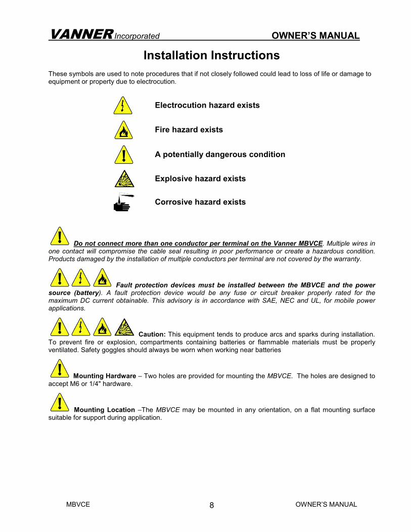
Installation Instructions These symbols are used to note procedures that if not closely followed could lead to loss of life or damage to equipment or property due to electrocution.
Electrocution hazard exists
Fire hazard exists
A potentially dangerous condition
Explosive hazard exists
Corrosive hazard exists
Do not connect more than one conductor per terminal on the Vanner MBVCE. Multiple wires in one contact will compromise the cable seal resulting in poor performance or create a hazardous condition. Products damaged by the installation of multiple conductors per terminal are not covered by the warranty.
Fault protection devices must be installed between the MBVCE and the power source (battery). A fault protection device would be any fuse or circuit breaker properly rated for the maximum DC current obtainable. This advisory is in accordance with SAE, NEC and UL, for mobile power applications.
Caution: This equipment tends to produce arcs and sparks during installation. To prevent fire or explosion, compartments containing batteries or flammable materials must be properly ventilated. Safety goggles should always be worn when working near batteries
Mounting Hardware – Two holes are provided for mounting the MBVCE. The holes are designed to accept M6 or 1/4" hardware.
Mounting Location –The MBVCE may be mounted in any orientation, on a flat mounting surface suitable for support during application.
VANNER Incorporated OWNER’S MANUAL
MBVCE OWNER’S MANUAL
9
MBVCE Definitions and Functionality
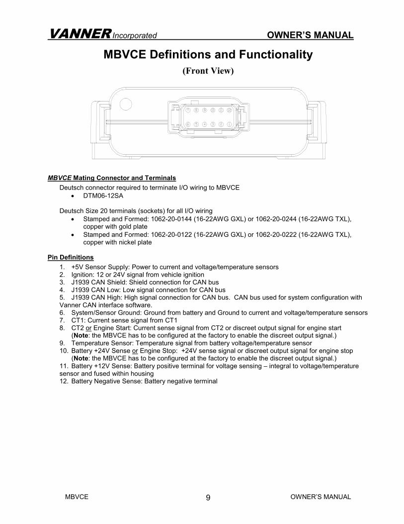
(Front View)
MBVCE Mating Connector and Terminals
Deutsch connector required to terminate I/O wiring to MBVCE
• DTM06-12SA
Deutsch Size 20 terminals (sockets) for all I/O wiring
• Stamped and Formed: 1062-20-0144 (16-22AWG GXL) or 1062-20-0244 (16-22AWG TXL), copper with gold plate
• Stamped and Formed: 1062-20-0122 (16-22AWG GXL) or 1062-20-0222 (16-22AWG TXL), copper with nickel plate
Pin Definitions
1. +5V Sensor Supply: Power to current and voltage/temperature sensors 2. Ignition: 12 or 24V signal from vehicle ignition 3. J1939 CAN Shield: Shield connection for CAN bus 4. J1939 CAN Low: Low signal connection for CAN bus 5. J1939 CAN High: High signal connection for CAN bus. CAN bus used for system configuration with Vanner CAN interface software. 6. System/Sensor Ground: Ground from battery and Ground to current and voltage/temperature sensors 7. CT1: Current sense signal from CT1 8. CT2 or Engine Start: Current sense signal from CT2 or discreet output signal for engine start (Note: the MBVCE has to be configured at the factory to enable the discreet output signal.) 9. Temperature Sensor: Temperature signal from battery voltage/temperature sensor 10. Battery +24V Sense or Engine Stop: +24V sense signal or discreet output signal for engine stop (Note: the MBVCE has to be configured at the factory to enable the discreet output signal.) 11. Battery +12V Sense: Battery positive terminal for voltage sensing – integral to voltage/temperature sensor and fused within housing 12. Battery Negative Sense: Battery negative terminal
VANNER Incorporated OWNER’S MANUAL
MBVCE OWNER’S MANUAL
10
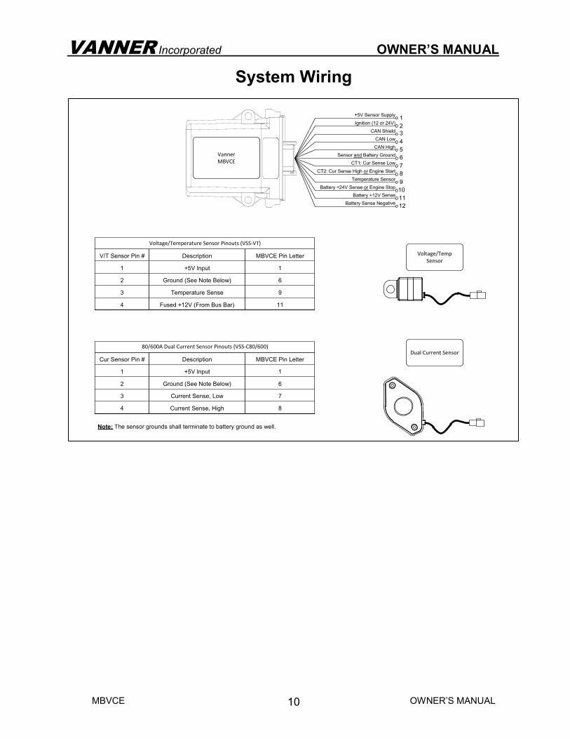
System Wiring
Note: The sensor grounds shall terminate to battery ground as well.
Voltage/Temp
Sensor
Dual Current Sensor
Description
+5V Input
Ground (See Note Below)
Temperature Sense
Fused +12V (From Bus Bar)
V/T Sensor Pin #
1
2
3
4
MBVCE Pin Letter
1
6
9
11
Voltage/Temperature Sensor Pinouts (VSS-VT)
Description
+5V Input
Ground (See Note Below)
Current Sense, Low
Current Sense, High
Cur Sensor Pin #
1
2
3
4
MBVCE Pin Letter
1
6
7
8
80/600A Dual Current Sensor Pinouts (VSS-C80/600)
1
2
3
CT2: Cur Sense High or Engine Start
CT1: Cur Sense Low
CAN High
CAN Low
Sensor and Battery Ground
CAN Shield
Ignition (12 or 24V)
+5V Sensor Supply
Temperature Sensor
Battery +24V Sense or Engine Stop
Battery +12V Sense
Battery Sense Negative
4
5
6
7
8
9
10
11
12
Vanner
MBVCE
VANNER Incorporated OWNER’S MANUAL
MBVCE OWNER’S MANUAL
11
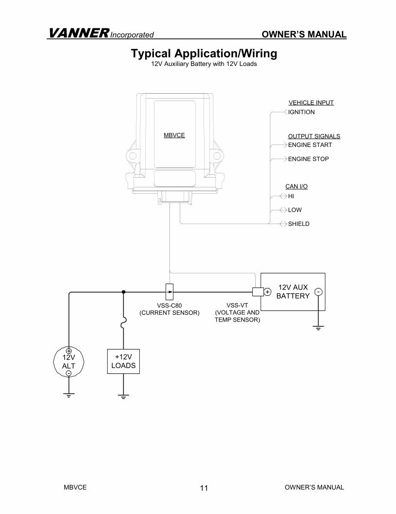
Typical Application/Wiring 12V Auxiliary Battery with 12V Loads
VEHICLE INPUT
IGNITION
ENGINE STOP
ENGINE START
OUTPUT SIGNALS
LOW
HI
SHIELD
CAN I/O
12V
ALT
+
-
VSS-C80
(CURRENT SENSOR)
VSS-VT
(VOLTAGE AND
TEMP SENSOR)
12V AUX
BATTERY-
+
+12V
LOADS
MBVCE
VANNER Incorporated OWNER’S MANUAL
MBVCE OWNER’S MANUAL
12
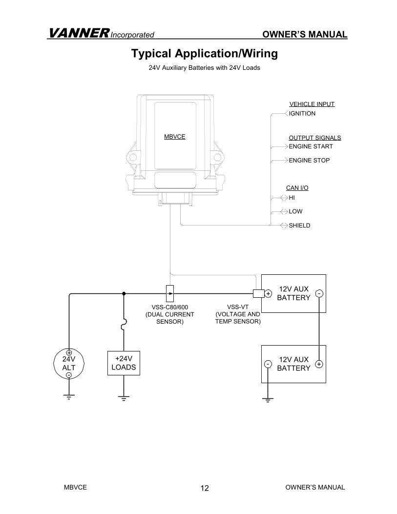
Typical Application/Wiring 24V Auxiliary Batteries with 24V Loads
VEHICLE INPUT
IGNITION
ENGINE STOP
ENGINE START
OUTPUT SIGNALS
LOW
HI
SHIELD
CAN I/O
24V
ALT
+
-
VSS-C80/600
(DUAL CURRENT
SENSOR)
VSS-VT
(VOLTAGE AND
TEMP SENSOR)
12V AUX
BATTERY-
+
+24V
LOADS
MBVCE
12V AUX
BATTERY
+-
VANNER Incorporated OWNER’S MANUAL
MBVCE OWNER’S MANUAL
13
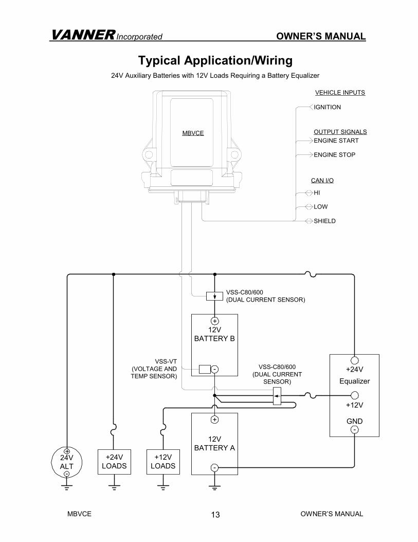
Typical Application/Wiring 24V Auxiliary Batteries with 12V Loads Requiring a Battery Equalizer
24V
ALT
+
-
-
+24V
GND
+12V
+12V
LOADS
Equalizer
12V
BATTERY B
+
-
12V
BATTERY A
+
-
VSS-C80/600
(DUAL CURRENT SENSOR)
+24V
LOADS
MBVCE
VEHICLE INPUTS
IGNITION
ENGINE STOP
ENGINE START
OUTPUT SIGNALS
LOW
HI
SHIELD
CAN I/O
VSS-VT
(VOLTAGE AND
TEMP SENSOR)
VSS-C80/600
(DUAL CURRENT
SENSOR)

VANNER Incorporated OWNER’S MANUAL
MBVCE OWNER’S MANUAL
14
VANNER Incorporated OWNER’S MANUAL
MBVCE OWNER’S MANUAL
15
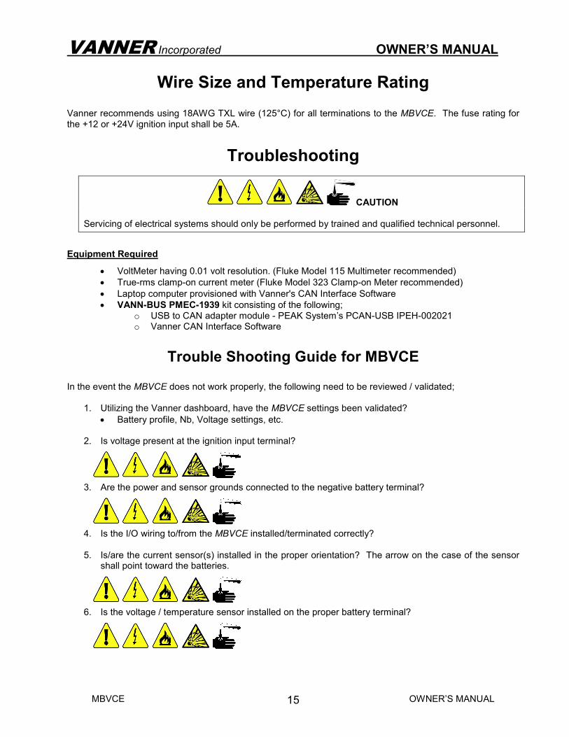
Wire Size and Temperature Rating Vanner recommends using 18AWG TXL wire (125°C) for all terminations to the MBVCE. The fuse rating for the +12 or +24V ignition input shall be 5A.
Troubleshooting
CAUTION Servicing of electrical systems should only be performed by trained and qualified technical personnel.
Equipment Required
• VoltMeter having 0.01 volt resolution. (Fluke Model 115 Multimeter recommended)
• True-rms clamp-on current meter (Fluke Model 323 Clamp-on Meter recommended)
• Laptop computer provisioned with Vanner's CAN Interface Software
• VANN-BUS PMEC-1939 kit consisting of the following; o USB to CAN adapter module - PEAK System’s PCAN-USB IPEH-002021 o Vanner CAN Interface Software
Trouble Shooting Guide for MBVCE
In the event the MBVCE does not work properly, the following need to be reviewed / validated;
1. Utilizing the Vanner dashboard, have the MBVCE settings been validated?
• Battery profile, Nb, Voltage settings, etc. 2. Is voltage present at the ignition input terminal?
3. Are the power and sensor grounds connected to the negative battery terminal?
4. Is the I/O wiring to/from the MBVCE installed/terminated correctly? 5. Is/are the current sensor(s) installed in the proper orientation? The arrow on the case of the sensor
shall point toward the batteries.
6. Is the voltage / temperature sensor installed on the proper battery terminal?
VANNER Incorporated OWNER’S MANUAL
MBVCE OWNER’S MANUAL
16
Trouble Shooting Guide Cont'd.
7. The following are faults reported by the MBVCE via CAN message and their potential causes;
• Current Sensor CT1 or CT2 Fault
• Either fault can be caused by improper wiring between the MBVCE module and the current sensor.
• Check to ensure proper pinouts and seating of the terminals in the connector housings.
• Check the integrity of the wires between the module and the current sensor.
• External Ground Fault (>0.75V)
• This fault is caused by missing or improper wiring of the battery ground sense lead.
• Check to ensure the battery ground sense wire is terminated in the correct position on the MBVCE connector.
• Check the integrity of the wire between the module and the negative battery terminal.
• Over Voltage Fault (>15V)
• This fault is caused by an issue with the vehicle's charging system.
• Check the alternator and/or regulator for issues.
• Under Voltage Fault (<12V)
• This fault is caused by an issue with the vehicle's charging system and/or wiring.
• Check the alternator and/or regulator for issues.
• Check the wiring between the charging system and batteries to ensure it's the proper size.
• Check for loose connections on the charging system and batteries.
• The voltage/temperature sensor has an internal fuse that could be blown. Check continuity between the copper tab and pin 4 of the sensor.
• Temperature Sensor Fault (< -40°C or >125°C)
• This fault can be caused by improper wiring between the MBVCE module and the voltage/temperature sensor.
• Check to ensure proper pinouts and seating of the terminals in the connector housings.
• Check the integrity of the wires between the module and the current sensor.

VANNER Incorporated OWNER’S MANUAL
MBVCE OWNER’S MANUAL
17
Vanner Repair Service In the event attempts to troubleshoot the MBVCE in the field, Vanner offers a quick turn-around factory repair service. Send the unit to the address on last page with a note instructing Vanner to repair it. Include your name, phone number, shipping address (not a P.O. Box Number), and your purchase order number.
VANNER Incorporated OWNER’S MANUAL
MBVCE OWNER’S MANUAL
18
Vanner Incorporated 4282 Reynolds Drive Hilliard, Ohio 43026
1-800-AC POWER (1-800-227-6937) Tel: 614-771-2718 Fax: 614-771-4904
www.vanner.com e-mail: [email protected]
Part Number D914833-B December, 1 2015 Printed in U.S.A.