Embed Size (px)
Citation preview
CHECK THE MASTER LIST— VERIFY THAT THIS IS THE CORRECT VERSION BEFORE USE
MSFC-STD-246 National Aeronautics and REVISION E Space Administration EFFECTIVE DATE: AUGUST 12, 2019
George C. Marshall Space Flight Center Marshall Space Flight Center, Alabama 35812
EM22
MSFC TECHNICAL STANDARD
STANDARD DESIGN AND OPERATIONAL CRITERIA
FOR CONTROLLED ENVIRONMENTAL AREAS
MEASUREMENT SYSTEM
INCH-POUND
Approved for Public Release; Distribution is Unlimited
MSFC Technical Standard EM22
Standard Design and Operational Criteria for Controlled Environmental Areas
Document No.: MSFC-STD-246 Revision: E Effective Date: August 12, 2019 Page 2 of 91
CHECK THE MASTER LIST – VERIFY THAT THIS IS THE CORRECT VERSION BEFORE USE
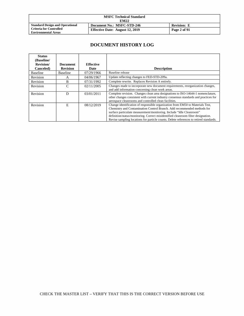
DOCUMENT HISTORY LOG
Status (Baseline/ Revision/ Canceled)
Document Revision
Effective Date
Description Baseline Baseline 07/29/1966 Baseline release Revision A 04/06/1967 Update reflecting changes to FED-STD-209a. Revision B 07/31/1992 Complete rewrite. Replaces Revision A entirely. Revision C 02/11/2005 Changes made to incorporate new document requirements, reorganization changes,
and add information concerning clean work areas. Revision D 03/01/2011 Complete revision. Changes clean area designations to ISO-14644-1 nomenclature,
other changes consistent with current industry consensus standards and practices for aerospace cleanrooms and controlled clean facilities.
Revision E 08/12/2019 Change identification of responsible organization from EM50 to Materials Test, Chemistry and Contamination Control Branch. Add recommended methods for surface particulate measurement/monitoring. Include “Idle Cleanroom” definition/status/monitoring. Correct misidentified cleanroom filter designation. Revise sampling locations for particle counts. Delete references to retired standards.
MSFC Technical Standard EM22
Standard Design and Operational Criteria for Controlled Environmental Areas
Document No.: MSFC-STD-246 Revision: E Effective Date: August 12, 2019 Page 3 of 91
CHECK THE MASTER LIST – VERIFY THAT THIS IS THE CORRECT VERSION BEFORE USE
FOREWORD The purpose of this Standard is to present data and information that relate to contamination control of MSFC environmentally controlled areas, cleanrooms, flow benches, and unidirectional clean air devices. It specifies environmental control operating standards to be used as minimum criteria for rooms and hardware requiring environmental control. This Standard provides guidelines for selecting the environmental facilities and operating conditions necessary for contamination control of critical aerospace hardware, and associated test hardware, facilities, Ground Support Equipment (GSE), and related components for MSFC-managed projects/programs during MSFC operations; it also lists quality control measures to ensure compliance.

MSFC Technical Standard EM22
Standard Design and Operational Criteria for Controlled Environmental Areas
Document No.: MSFC-STD-246 Revision: E Effective Date: August 12, 2019 Page 4 of 91
CHECK THE MASTER LIST – VERIFY THAT THIS IS THE CORRECT VERSION BEFORE USE
TABLE OF CONTENTS PARAGRAPH PAGE DOCUMENT HISTORY LOG ................................................................................................... 2
FOREWORD................................................................................................................................. 3
TABLE OF CONTENTS ............................................................................................................. 4
1. SCOPE ............................................................................................................................... 6
1.1 Scope. .................................................................................................................................. 6 1.2 Authority. ............................................................................................................................ 6 1.3 Responsibility. .................................................................................................................... 6 1.4 Specification on Contracts. ................................................................................................. 7
2. APPLICABLE DOCUMENTS ........................................................................................ 7
2.1 Applicable Documents. ....................................................................................................... 7 2.2 Reference Documents. ........................................................................................................ 8 3. DEFINITIONS ................................................................................................................ 10 3.1 Acronyms used in this standard. ....................................................................................... 10 3.2 Glossary of Terms. ............................................................................................................ 12
4. GENERAL REQUIREMENTS ..................................................................................... 15
4.1 Facility Classification and Identification. ......................................................................... 15 4.2 Determination of Required Environmental Controls. ....................................................... 17 4.3 Facility Operating Procedure. ........................................................................................... 18 4.4 General Operating Practices. ............................................................................................ 20
5.0 DETAILED REQUIREMENTS .................................................................................... 29
5.1 Common Design and Construction Criteria for Clean Facilities. ..................................... 29 5.2 Continuous Operation of Air Systems. ............................................................................. 33 5.3 Controlled Areas Class 8.5. .............................................................................................. 33 5.4 Clean Work Areas Class 8. ............................................................................................... 35 5.5 Conventional Flow Cleanrooms. ...................................................................................... 37 5.6 Unidirectional Flow Cleanrooms. ..................................................................................... 47 5.7 Unidirectional Flow Bench/Clean Work Station. ............................................................. 53
MSFC Technical Standard EM22
Standard Design and Operational Criteria for Controlled Environmental Areas
Document No.: MSFC-STD-246 Revision: E Effective Date: August 12, 2019 Page 5 of 91
CHECK THE MASTER LIST – VERIFY THAT THIS IS THE CORRECT VERSION BEFORE USE
5.8 Clean Tents and Other Unidirectional Flow Clean Air Devices. ...................................... 61 5.9 Certification and Monitoring Practices. ............................................................................ 65
6.0 NOTES ............................................................................................................................. 72
6.1 Contamination Control...................................................................................................... 72 6.2 Establishment of Hardware Cleanliness Requirements. ................................................... 77
APPENDICIES A. Particulate Sampling In Cleanrooms And Other Controlled Clean Areas ........................ 79 B. Monitoring Of Cleanroom Garments ................................................................................ 84 C. Flow Bench General Operating Procedures ...................................................................... 88 TABLES
I. Environmental Standards for Clean Facilities .................................................................. 89
FIGURES 1. Conventional Flow Cleanroom Air Patterns ..................................................................... 38
2. Conventional Flow Cleanroom Layout ............................................................................. 39
3. Unidirectional Flow Cleanroom Air Patterns ................................................................... 48
4. Unidirectional Cross-Flow Cleanroom ............................................................................. 49
5. Unidirectional Down-Flow Cleanroom ............................................................................ 49
6. Horizontal Flow Bench ..................................................................................................... 54
7. Vertical Flow Bench (non-recirculating) .......................................................................... 55
8. Down-flow Clean Tent ..................................................................................................... 63
9. Unidirectional Flow Clean Tunnel.................................................................................... 64
10. Particulate Fallout vs. Time for Cleanrooms* .................................................................. 73
11. Cleanroom Sampling Plan ................................................................................................ 82
12. Cleanroom Garment Sampling Locations ......................................................................... 85
MSFC Technical Standard EM22
Standard Design and Operational Criteria for Controlled Environmental Areas
Document No.: MSFC-STD-246 Revision: E Effective Date: August 12, 2019 Page 6 of 91
CHECK THE MASTER LIST – VERIFY THAT THIS IS THE CORRECT VERSION BEFORE USE
1. SCOPE
1.1 Scope.
This document establishes Marshall Space Flight Center (MSFC's) standard design and operational criteria for controlled environmental areas including standard classes of air cleanliness for airborne particulate levels and standard operations for control of particulate and condensables in cleanrooms and clean work areas. It prescribes methods for verification and monitoring of facility cleanliness and cleanliness of cleanroom garments. 1.2 Authority.
This Standard is prepared by MSFC for its internal use and that of its contractors in accordance with MPR 5340.1, “Controlled Work Area, Clean Room, and Flow Bench Operations”. MPR 1280.2, “Process Control”, requires that process owners determine the suitable work environment needed to achieve conformity to product requirements. Clean work environments and associated clean facility fluids (e.g., high purity air, deionized water) are frequently required to achieve and maintain the required cleanliness of aerospace products. This standard applies the following: all mandatory actions (i.e., requirements) are denoted by statements containing the term, “shall.” The terms: “may” or “can” denote discretionary privilege or permission, “should” denotes a good practice and is recommended, but not required, “will” denotes expected outcome, and “are/is” denotes descriptive material.
1.3 Responsibility.
The Marshall Space Flight Center is responsible for implementing this standard in accordance with MPR 5340.1. 1.3.1 Each owner/operator of an environmentally controlled clean facility is responsible for implementing the requirements indicated by this Standard. 1.3.2 A single Custodian designated for the clean facility will be responsible for the implementation of this Standard within that facility. 1.3.3 At MSFC, the Materials and Processes (M&P) Laboratory, Materials Test, Chemistry and Contamination Control Branch is responsible for sampling to ensure conformance and compliance. 1.3.4 At MSFC’s Michoud Assembly Facility (MAF), the Manufacturing Support & Facility Operations Contractor (MSFOC) is responsible for sampling to ensure conformance and compliance. 1.3.5 A Contamination Control Engineer (CCE) from the M&P Laboratory, Materials Test, Chemistry and Contamination Control Branch will be designated for each cleanroom with the
MSFC Technical Standard EM22
Standard Design and Operational Criteria for Controlled Environmental Areas
Document No.: MSFC-STD-246 Revision: E Effective Date: August 12, 2019 Page 7 of 91
CHECK THE MASTER LIST – VERIFY THAT THIS IS THE CORRECT VERSION BEFORE USE
responsibility to provide guidance to ensure compliance with this Standard and assistance for periodic audits and verification of programmatic requirements compliance. 1.4 Specification on Contracts.
When this document is specified on a contract, the contractor may pursue substituting equivalent documents that meet the intent of this Standard, with the approval of the NASA procuring activity Contamination Control Engineer (CCE). Such substitution may be approved via NASA approval of the contractor Contamination Control Plan (delivered in accordance with NASA-STD-6016, “Spacecraft Requirements for Materials and Processes”) or other contract data submittal requirements in which the substituting documents are specified.
2. APPLICABLE DOCUMENTS
2.1 Applicable Documents. Documents listed below provide requirements, specifications, standards, and procedures applicable to this Standard. For each of these documents, the latest revision in effect at the date of contact award (for contractors) or the date of Operating Procedure release (MSFC operated clean facilities) shall apply. 2.1.1 Government Documents. NASA
MPR 1280.2 Process Control MPR 5340.1 Controlled Work Area, Clean Room, and Flow Bench Operations MSFC-STD-3535 Standard for Propellants and Pressurants Used for Test and Test
Support Activities at SSC and MSFC
2.1.2 Non-Government Documents.
American Society of Heating, Refrigerating, and Air-Conditioning Engineers, Inc. ANSI/ASHRAE 52.2 Method of Testing General Ventilation Air-Cleaning Devices for
Removal Efficiency by Particle Size ASTM International ASTM E 1216 Standard Practice for Sampling for Particulate Contamination by
Tape Lift Institute of Environmental Sciences and Technology
MSFC Technical Standard EM22
Standard Design and Operational Criteria for Controlled Environmental Areas
Document No.: MSFC-STD-246 Revision: E Effective Date: August 12, 2019 Page 8 of 91
CHECK THE MASTER LIST – VERIFY THAT THIS IS THE CORRECT VERSION BEFORE USE
IEST-RP-CC001 HEPA and ULPA Filters International Organization for Standardization ISO 14644-1 Cleanrooms and Associated Controlled Environments – Part 1: Classification of Air Cleanliness
2.2 Reference Documents. Documents listed below are provided as background or supplemental information for the users of this standard. The listing in this section does not levy any new or relieve any specific requirements that are imposed by this standard or by other contractual documents. 2.2.1 Government Documents. Military
MIL-HDBK-1028 Environmental Control – Design of Clean Rooms NASA
MSFC-PROC-1832 The Sampling and Analysis of Nonvolatile Residue Content on
Critical Surfaces MSFC-SPEC-2223 Outgassing Test for Materials Associated with Sensitive Surfaces
Used in an Ambient Environment MSFC-STD-3598 Standard for Foreign Object Damage/Foreign Object Debris (FOD)
Prevention NASA-STD-5017 Design and Development Requirements for Mechanisms NASA-STD-6016 Spacecraft Requirements for Materials and Processes NASA-STD-8739.1 Workmanship Standard for Polymeric Application on Electronic
Assemblies NASA-STD-8739.5 Fiber Optic Terminations, Cable Assemblies, and Installation
2.2.2 Non-Government Documents.
ASTM International
MSFC Technical Standard EM22
Standard Design and Operational Criteria for Controlled Environmental Areas
Document No.: MSFC-STD-246 Revision: E Effective Date: August 12, 2019 Page 9 of 91
CHECK THE MASTER LIST – VERIFY THAT THIS IS THE CORRECT VERSION BEFORE USE
ASTM E 1235 Standard Test Method for Gravimetric Determination of Nonvolatile Residue (NVR) in Environmentally Controlled Areas for Spacecraft
ASTM E 1548 Standard Practice for Preparation of Aerospace Contamination
Control Plans ASTM E 1549 Standard Specification for ESD Controlled Garments Required in
Cleanrooms and Controlled Environments for Spacecraft for Non-Hazardous and Hazardous Operations
ASTM E 1560 Standard Test Method for Gravimetric Determination of
Nonvolatile Residue from Cleanroom Wipers ASTM E 1731 Standard Test Method for Gravimetric Determination of
Nonvolatile Residue from Cleanroom Gloves ASTM E 2042 Standard Practice for Cleaning and Maintaining Controlled Areas
and Clean Rooms ASTM E 2088 Standard Practice for Selecting, Preparing, Exposing, and
Analyzing Witness Surfaces for Measuring Particle Deposition in Cleanrooms and Associated Controlled Environments
ASTM E 2217 Standard Practice for Design and Construction of Aerospace
Cleanrooms and Contamination Controlled Areas ASTM E 2352 Standard Practice for Aerospace Cleanrooms and Associated
Controlled Environments – Cleanroom Operations ASTM F 303 Standard Practices for Sampling for Particles in Aerospace Fluids
and Components ASTM F 312 Standard Test Methods for Microscopical Sizing and Counting
Particles from Aerospace Fluids on Membrane Filters ASTM F 331 Standard Test Method for Nonvolatile Residue of Solvent Extract
from Aerospace Components (Using Flash Evaporator) Electrostatic Discharge Association ANSI/ESD S20.20 ESD Association Standard for the Development of an Electrostatic
Discharge Control Program for Protection of Electrical and
MSFC Technical Standard EM22
Standard Design and Operational Criteria for Controlled Environmental Areas
Document No.: MSFC-STD-246 Revision: E Effective Date: August 12, 2019 Page 10 of 91
CHECK THE MASTER LIST – VERIFY THAT THIS IS THE CORRECT VERSION BEFORE USE
Electronic Parts, Assemblies and Equipment (Excluding Electrically Initiated Explosive Devices)
Institute of Environmental Sciences and Technology
IEST-RP-CC002 Unidirectional Flow Clean Air Devices IEST-RP-CC003 Garment System Considerations for Cleanrooms and Other
Controlled Environments IEST-RP-CC004 Evaluating Wiping Materials Used in Cleanrooms and Other
Controlled Environments IEST-RP-CC005 Gloves and Finger Cots Used in Cleanrooms and Other Controlled
Environments IEST-RP-CC006 Testing Cleanrooms IEST-RP-CC008 High-Efficiency Gas-Phase Adsorber Cells IEST-RP-CC012 Considerations in Cleanroom Design IEST-RP-CC014 Calibration and Characterization of Optical Particle Counters IEST-RP-CC023 Microorganisms in Cleanrooms IEST-RP-CC034 HEPA and ULPA Filter Leak Tests IEST-STD-CC1246 Product Cleanliness Levels and Contamination Control Program International Organization for Standardization ISO 15388 Space Systems – Contamination and Cleanliness Control
3. DEFINITIONS 3.1 Acronyms used in this standard. The acronyms used in this standard are defined as follows: ASTM ASTM International (formerly known as the American
Society for Testing and Materials) CCE Contamination Control Engineer
MSFC Technical Standard EM22
Standard Design and Operational Criteria for Controlled Environmental Areas
Document No.: MSFC-STD-246 Revision: E Effective Date: August 12, 2019 Page 11 of 91
CHECK THE MASTER LIST – VERIFY THAT THIS IS THE CORRECT VERSION BEFORE USE
cfm Cubic feet per minute CWA Clean Work Area DOP Dioctyl (2-ethyl hexyl) Phthalate
EEE Electrical, electronic, and electromechanical
ESD Electrostatic Discharge GSE Ground Support Equipment
FOD Foreign object damage/foreign object debris HEPA High Efficiency Particulate Air
HVAC Heating Ventilating and Air Conditioning IEST Institute of Environmental Sciences and Technology μm Micrometer
MAF Michoud Assembly Facility M&P Materials and Processes Laboratory
MERV Minimum Efficiency Reporting Value MSFC Marshall Space Flight Center
MSFOC Manufacturing Support & Facility Operations Contractor
NIST National Institute of Standards and Technology
NVR Nonvolatile Residue
Pa Pascal
ppm Parts per million PSL Polystyrene Latex
STE Special Test Equipment
MSFC Technical Standard EM22
Standard Design and Operational Criteria for Controlled Environmental Areas
Document No.: MSFC-STD-246 Revision: E Effective Date: August 12, 2019 Page 12 of 91
CHECK THE MASTER LIST – VERIFY THAT THIS IS THE CORRECT VERSION BEFORE USE
ULPA Ultra Low Penetration Air 3.2 Glossary of Terms. 3.2.1 AIRLOCK: An enclosed area between a cleanroom and the entry from the outside area, designed to prevent contaminated outside air from infiltrating by pressure gradient. 3.2.2 AIR SHOWER: An area between the entrance to a cleanroom and the entry from an airlock area which delivers a shower of clean air that removes particulate from a person’s garments. May also be integral with the airlock 3.2.3 AS-BUILT: The occupancy state at which a clean facility is complete and ready for operation, with all services connected and functional, but without production equipment or personnel present. 3.2.4 AT-REST: The occupancy state at which a clean facility is complete with production equipment installed and operating, but no personnel present. 3.2.5 BUNNY SUIT: A common term for a full coverage cleanroom ensemble consisting of a coverall, hood, booties, and gloves. 3.2.6 CLEANROOM: An enclosed area employing control over the particulate matter in air, with temperature, humidity, pressure and condensables controlled as required. 3.2.7 CLEANROOM CLASS: A standard level of airborne particulate cleanliness within a facility defined in accordance with ISO 14644-1, “Cleanrooms and Associated Controlled Environments – Part 1: Classification of Air Cleanliness”. 3.2.8 CLEANROOM GARMENT: Any part of or a complete uniform of special clothing, constructed of low-linting material, worn in environmentally controlled areas as specified in this Standard. These garments may include coveralls, boot type shoe covers, and hoods, etc. 3.2.9 CLEAN TENT: A unidirectional down-flow clean air device consisting of an air handling unit with High Efficiency Particulate Air (HEPA) filtration on a modular frame with suspended soft walls. 3.2.10 CLEAN WORKSTATION: See Flow Bench 3.2.11 CONTAMINATION: Any particulate, molecular, non-particulate or biological entity that can adversely affect the product or process 3.2.12 CONTAMINATION CONTROL: The process of minimizing contamination in a work area by using environmentally controlled facilities, materials and procedures.
MSFC Technical Standard EM22
Standard Design and Operational Criteria for Controlled Environmental Areas
Document No.: MSFC-STD-246 Revision: E Effective Date: August 12, 2019 Page 13 of 91
CHECK THE MASTER LIST – VERIFY THAT THIS IS THE CORRECT VERSION BEFORE USE
3.2.13 CONTAMINATION CONTROL ENGINEER: Individual from the Materials Test, Chemistry and Contamination Control Branch responsible for providing guidance in contamination control and prevention for MSFC clean facilities. 3.2.14 CONTROLLED AREA: An air conditioned work space or room in which the particle concentration is controlled to be lower than that of normal air conditioned spaces. A controlled area is not classified as a cleanroom, but some special filtration is required as specified in this Standard. Such an area is used for processing of items which do not require the strict environmental controls of a cleanroom, but which should be segregated from less clean or contamination generating operations. 3.2.15 CONVENTIONAL FLOW CLEANROOM (FACILITY): A cleanroom (facility) with non-unidirectional flow characteristics. This type of cleanroom maintains air cleanliness by continuous dilution and re-circulating air filtration to remove contaminants generated by operations within the facility. 3.2.16 COVERALLS: A one piece, full length garment that covers the body from the neck to the wrists and ankles. May include an attached hood and/or booties. 3.2.17 CUSTODIAN: Individual tasked with maintaining (1) controlled work area, cleanroom, or flow bench in operational order, (2) facility operational procedures and (3) insuring requirements of this document are met. 3.2.18 DISCRETE PARTICLE COUNTER: A light-scattering device or other instrument with display and/or recording means to count and size discrete particles in a specific volume of air. 3.2.19 ENVIRONMENTAL CONTROL: A collective term for the positive control of atmospheric conditions within a designated area whereby particulate contamination, temperature, pressure, condensables, and humidity can be controlled and measured. 3.2.20 FIBER: A particle whose length-to-width ration is in excess of 10 to 1 (minimum length of 100 μm). 3.2.21 FLOW BENCH: A clean work station or similar working enclosure with its own HEPA filtered air supply exhausting over the work area in a unidirectional airflow pattern 3.2.22 FROCK: A three-quarter-length garment employing military collar design and full front closure; intended to cover the arms and torso, and meet the knees of the wearer 3.2.23 HIGH EFFICIENCY PARTICULATE AIR (HEPA) FILTER: An expendable, extended media dry type filter in a rigid frame having a minimum particle collection efficiency of 99.97 percent for 0.3 μm particles and larger.
MSFC Technical Standard EM22
Standard Design and Operational Criteria for Controlled Environmental Areas
Document No.: MSFC-STD-246 Revision: E Effective Date: August 12, 2019 Page 14 of 91
CHECK THE MASTER LIST – VERIFY THAT THIS IS THE CORRECT VERSION BEFORE USE
3.2.24 HEATING, VENTILATING, AND AIR CONDITIONING (HVAC) SYSTEM: A general term to describe the mechanical system for control and conditioning of air in an environmentally controlled facility to maintain specified standards of temperature and humidity. 3.2.25 IDLE CLEANROOM: A work area with no flight/critical hardware and reduced operations. Monitoring checks as requested by customer. Recertification required to reclassify cleanroom per A3.5. 3.2.26 LUX: A unit of illumination equal to one lumen per square meter (approximately 0.093 foot candle.) 3.2.27 MICROMETER (μm): A unit of measurement equal to one-millionth of a meter or approximately 0.00003937 inch. (25 micrometers are approximately 0.001 inch.) Also referred to as a micron. 3.2.28 NON-UNIDIRECTIONAL FLOW: Airflow which does not meet the definition of unidirectional airflow by having either multiple pass circulating characteristics (eddies) or nonparallel flow vectors. Also known as turbulent flow. 3.2.29 NONVOLATILE RESIDUE (NVR): The material remaining after filtration and temperature controlled evaporation of a volatile liquid (usually measured in milligrams per unit area or unit volume). 3.2.30 OPERATIONAL: The occupancy state at which a clean facility is in normal operation with all services functioning and with production equipment and personnel present and performing their normal work functions. 3.2.31 PARTICLE: A small discrete mass of solid matter, usually measured in micrometers. 3.2.32 PARTICLE CONCENTRATION: Concentration expressed in terms of the number of particles per unit volume of air or other gas. 3.2.33 PARTICLE SIZE: The apparent maximum linear dimension of a particle in the plane of observation as observed with an optical microscope, or an equivalent diameter of a particle detected by automatic instrumentation. An equivalent diameter is the same as that of a reference sphere having known properties and producing an identical response in a sensing instrument as the particle being measured. 3.2.34 PARTICULATE MATTER: A general term applied to particles of material suspended in gases or liquids, or resident as foreign matter on surfaces. 3.2.35 REVERSE FLOW BENCH: A flow bench in which the direction of air flow is reversed in order to filter and contain contaminants generated by an operation performed at the work station prior to exhausting into the room.
MSFC Technical Standard EM22
Standard Design and Operational Criteria for Controlled Environmental Areas
Document No.: MSFC-STD-246 Revision: E Effective Date: August 12, 2019 Page 15 of 91
CHECK THE MASTER LIST – VERIFY THAT THIS IS THE CORRECT VERSION BEFORE USE
3.2.36 UNIDIRECTIONAL FLOW: Airflow that flows in a single pass in a single direction through a cleanroom or clean zone with generally parallel streamlines. Formerly referred to as laminar airflow. 3.2.37 UNIDIRECTIONAL FLOW CLEANROOM: A cleanroom in which unidirectional air flow characteristics predominate throughout the entire room with a minimum of eddies. 4. GENERAL REQUIREMENTS 4.1 Facility Classification and Identification. 4.1.1 Types of Environmentally Controlled Clean Facilities. Controlled clean facilities shall be classified based on the maximum allowable number of particles equal to or larger than 0.5 micrometers (μm) per cubic unit of air within the facility, measured in the operational condition. The current international standard for such classifications is defined in ISO 14644-1, with maximum limits defined per cubic meter of air MSFC has historically classified particulate count limits per cubic foot of air. Table I, at the end of this document, provides the allowable particle count limits for each Cleanroom Class using both sets of units. NOTE: Industry standards, both historical and current, use metric units (micrometers and milligrams) to measure contaminants. This has historically resulted in the use of some mixed metric/English units such as mg/ft2. Users may continue to report measurements in the mixed metric/English units when their instrumentation is pre-set for such units, provided that the units are clearly documented. Six basic types of environmentally controlled clean facilities are defined in this document to achieve and maintain contamination control while work is accomplished. They are: a. Controlled Area Class 8.5 – Section 5.3. b. Clean Work Area (CWA) Class 8 – Section 5.4. c. Conventional (non-unidirectional) Flow Cleanroom, Class 8or Class 7 – Section 5.5
d. Unidirectional Flow Cleanroom, Class 8 through Class 5 – Section 5.6 e. Unidirectional Flow Bench/Clean Work Station Class 5 – Section 5.7. f. Clean Tents and other unidirectional flow clean air devices (Class varies) – Section 5.8 4.1.2 Limits for Particles Larger than 5.0 μm
MSFC Technical Standard EM22
Standard Design and Operational Criteria for Controlled Environmental Areas
Document No.: MSFC-STD-246 Revision: E Effective Date: August 12, 2019 Page 16 of 91
CHECK THE MASTER LIST – VERIFY THAT THIS IS THE CORRECT VERSION BEFORE USE
Concentration limits have been established in ISO-14644-1 for particles 5.0 μm and larger for cleanrooms Class 6 and up. Measurement of this size range is not statistically valid in facilities Class 5 and cleaner. 4.1.3 Alternate Classifications Alternate classifications may be used when required to define the particulate cleanliness of a facility. Alternate classifications shall be stated as the maximum allowable number of particles equal to or larger than 0.5 μm per cubic unit of air within facility, measured in the operational condition. ISO 14644-1 provides equations and instructions for the calculation of corresponding ISO Class numbers (such as Class 6.5) and limits for particles equal to or larger than 5.0 μm. 4.1.4 Environmental Control Requirements. Environmentally controlled clean facilities shall conform to the minimum standards specified in Table I except when tailored in accordance with section 4.1.4.2. 4.1.4.1 When an alternate classification is used, the design and operational requirements of the next cleaner standard classification shall apply. 4.1.4.2 Exceptions to Table I may be granted by the Contamination Control Engineer (CCE) (for MSFC and Michoud Assembly Facility (MAF)-operated facilities) or by the Procuring Activity CCE (for subcontractors) on a case-by-case basis for each facility as warranted. Exceptions to Table I shall be specified in the applicable Operating Procedure. 4.1.5 Facility Identification The following information shall be conspicuously posted at the main personnel entrance to the environmentally controlled facility or posted immediately outside the work area of a clean work station or temporary clean enclosure:
• Type of facility (e.g. Class 8.5 Controlled Area)
• Custodian and alternate names, organization code and phone numbers
• Maximum number of occupants (optional – as required to maintain particle limits)
• Most recent facility sampling results data (MSFC Form 3163 or equivalent)
• Gowning requirements
• A poster of work rules (or a copy of the Operating Procedure available nearby) as determined by user requirements
• Operational status (Active, Deactivated or Idle) 4.1.6 Foreign Object Damage/Foreign Object Debris.
MSFC Technical Standard EM22
Standard Design and Operational Criteria for Controlled Environmental Areas
Document No.: MSFC-STD-246 Revision: E Effective Date: August 12, 2019 Page 17 of 91
CHECK THE MASTER LIST – VERIFY THAT THIS IS THE CORRECT VERSION BEFORE USE
Clean facilities, while effective at controlling airborne contaminants, are not generally effective at controlling foreign object damage/foreign object debris (FOD). When FOD prevention is required to limit the risk of hardware damage due to entrapment of debris or impact by foreign objects, the clean facility may also be designated and controlled as a FOD Sensitive Area in accordance with MSFC-STD-3598, “Standard for Foreign Object Damage/Foreign Object Debris (FOD) Prevention”. When a clean facility is also designated as a FOD Sensitive Area, the clean facility Custodian and the FOD Site Manager (as defined in MSFC-STD-3598) should be the same person. 4.2 Determination of Required Environmental Controls. Except when specified by contract, the requirement for an environmentally controlled area and the required level of control for that area shall be determined by the cognizant CCE or M&P Engineer based on the cleanliness requirements of the hardware to be processed and the operations to be performed within the facility. 4.2.1 Cleanliness requirements for the hardware are derived based on hardware performance criteria. See section 6.2 for guidance on establishing hardware cleanliness requirements. 4.2.2 Cleanliness requirements may be imposed on a hardware item that is less sensitive to contamination in order to limit cross-contamination of a more sensitive hardware item. This in turn may drive environmental cleanliness requirements. 4.2.3 Requirements for environmental control should be selected based on all of the following:
• Predicted duration of exposure of the hardware within the facility combined with expected contaminant deposition rates during operations within the facility. Utilization of protective covers should be considered when calculating duration of exposure.
• Hardware limits for accumulated particulate and smallest particle size that must be
controlled.
• Hardware and process sensitivity to temperature and humidity including considerations for electrostatic discharge (ESD) control, processing of materials such as composites, adhesives, and primers, and worker comfort (perspiration, fatigue, etc.).
• Allowable hardware limits for nonvolatile residue and/or microbiological contaminants, when applicable.
• Project and industry experience with similar hardware and equivalent end item cleanliness levels.
4.2.4 No facility will compensate for excessive contamination generated within the facility. In addition to an effective facility design, the Custodian shall institute corresponding controls for operation and maintenance of the facility. Achieving and maintaining the required cleanliness
MSFC Technical Standard EM22
Standard Design and Operational Criteria for Controlled Environmental Areas
Document No.: MSFC-STD-246 Revision: E Effective Date: August 12, 2019 Page 18 of 91
CHECK THE MASTER LIST – VERIFY THAT THIS IS THE CORRECT VERSION BEFORE USE
level of a hardware end item depends on the operating procedures, maintenance protocols, and hardware exposure time in the clean facility. 4.2.5 Facilities intended to accommodate multiple payloads or hardware customers shall be designed to accommodate the anticipated cleanliness level of the most stringent end item. The facility Operating Procedure may be adjusted to satisfy the requirements for the current occupant, with the approval of the facility Custodian. The Custodian shall evaluate proposed changes to the Operating Procedure to assure that they will not degrade the condition of the facility to the extent that future user operations could be compromised.
4.3 Facility Operating Procedure. 4.3.1 Operating Procedure Requirement. Each environmentally controlled clean facility shall have a written Operating Procedure that implements this Standard, with the designated Custodian being responsible for preparing such a procedure. 4.3.1.1 Operating Procedures for cleanrooms and CWAs shall address the following criteria, as a minimum.
• Purpose of the facility /hardware to be processed
• Location and defined boundaries for the facility including airlocks and gowning facilities
• Airborne cleanliness class per this document
• Temperature requirements
• Relative humidity requirements
• Procedures to be followed when the facility exceeds the environmental limits established in the operating procedure (e.g., stop work, cover sensitive hardware, don wrist straps)
• Fluid purity requirements for plumbed delivery systems such as high purity air and water, as applicable
• Access controls
• Garment requirements and frequency of change
• Restricted/prohibited materials or a list of approved supplies, as applicable
• Entry and exit procedures for personnel and hardware, including location of shoe cleaners and sticky mats and provisions for cleaning and packaging/unpackaging of products
MSFC Technical Standard EM22
Standard Design and Operational Criteria for Controlled Environmental Areas
Document No.: MSFC-STD-246 Revision: E Effective Date: August 12, 2019 Page 19 of 91
CHECK THE MASTER LIST – VERIFY THAT THIS IS THE CORRECT VERSION BEFORE USE
• Facility cleaning and maintenance; frequency, methods, approved materials
• Facility certification and monitoring requirements and frequency, to include required locations for monitoring of airborne particulate; continuous monitoring requirements if applicable
• Personnel training requirements
• Other parameters that deviate from those specified in Table I
• Additional restrictions or monitoring requirements, as applicable (electrostatic discharge control, particle deposition rate, NVR deposition rate, etc.)
4.3.1.2 Operating Procedures for Class 8.5 Controlled Areas, flow benches, clean tents, and other unidirectional clean air devices shall address operational criteria from 4.3.1.1 as necessary to define the operating requirements for the facility. 4.3.1.3 A general Flow Bench operating procedure is provided in Appendix C. This operating procedure may be tailored as needed for the specific flow bench. 4.3.2 Documentation of Operating Procedure. The Operating Procedure for the clean facility may be documented as an Organizational Work Instruction, a Project document issuance, or other controlled publication auditable by the cognizant Quality Assurance organization. A copy of the Operating Procedure shall be submitted to the M&P Laboratory, Materials Test, Chemistry and Contamination Control Branch for review. 4.3.3 Deviations from this Standard. 4.3.3.1 Deviations from the requirements of this Standard based upon the requirements for hardware processing operations to be performed in the facility, including exceptions to Table I, shall be stated in the facility Operating Procedure and approved by the Materials Test, Chemistry and Contamination Control Branch. 4.3.3.2 Approval of deviations to this standard shall be documented via a memo from the branch chief, Materials Test, Chemistry and Contamination Control Branch, or designee. 4.3.3.3 When the Operating Procedure deviates from the environmental monitoring requirements specified in Table I (pass/fail criteria or frequency), the Operating Procedure with deviations identified shall be provided to the organization(s) that will perform facility certification and routine monitoring as specified in section 5.9. 4.3.4 Precedence of Operating Requirements.
MSFC Technical Standard EM22
Standard Design and Operational Criteria for Controlled Environmental Areas
Document No.: MSFC-STD-246 Revision: E Effective Date: August 12, 2019 Page 20 of 91
CHECK THE MASTER LIST – VERIFY THAT THIS IS THE CORRECT VERSION BEFORE USE
The operating requirements for the facility established in the approved Operating Procedure shall take precedence over this standard for quality monitoring purposes. 4.4 General Operating Practices. The following general operating practices, tailored to the level of cleanliness and type of operation, shall apply within all clean facilities as specified herein. For further information, reference ASTM E 2352, “Standard Practice for Aerospace Cleanrooms and Associated Controlled Environments – Cleanroom Operations”. 4.4.1 Personnel. 4.4.1.1 General Practices When operating any type of environmentally controlled clean facility, the greatest source of particulate contamination comes directly from the personnel within the area. All personnel, without exception, entering the clean facility shall obey the gowning requirements, operational work rules, and code of conduct established for that facility. ALL CLEAN FACILITY VISITORS, WITHOUT EXCEPTION, MUST OBSERVE ALL CLEAN FACILITY RULES. 4.4.1.2 Access Control Clean facilities controlled per this document are restricted areas. Access shall be limited to authorized individuals. 4.4.1.3 Personnel Practices Personnel with skin or upper respiratory ailments shall not be allowed to work in the clean facility if their condition could adversely affect the environment. Personnel with colds, temporary sneezing and coughing, or severe sunburns may require temporary assignment outside of the environmentally controlled area. Some conditions may be accommodated by the use of garments specific to the medical condition, such as face masks or gloves. Examples of physiological problems that are detrimental to clean atmospheres are as follows:
• Allergies to synthetic fabric, solvents, or other materials used in the facility
• Profuse nasal discharge
• Skin conditions which result in above normal skin shedding
• High amounts of acid found in moisture on hands
MSFC Technical Standard EM22
Standard Design and Operational Criteria for Controlled Environmental Areas
Document No.: MSFC-STD-246 Revision: E Effective Date: August 12, 2019 Page 21 of 91
CHECK THE MASTER LIST – VERIFY THAT THIS IS THE CORRECT VERSION BEFORE USE
• Severe nervous conditions, itching, scratching, or claustrophobia
• Emphysema 4.4.1.4 Personal Hygiene: All personnel shall be required to maintain good personal hygiene for clean facility operations. The high degree of cleanliness required necessitates the development of the following habits: a. Wear clean under and outer garments b. Avoid scratching or rubbing one's head or exposed skin areas c. Do not wear fingernail polish, cosmetics, colognes, or hand lotion within the cleanroom (as specified in the facility Operating Procedure) d. Keep hands, fingernails, and face clean e. Exit cleanroom to comb or untangle hair 4.4.2 Operating Disciplines within the Clean Facility. 4.4.2.1 Supervisor and employee discipline is fundamental to the quality of cleanroom products. All cleanroom personnel shall be required to practice good cleanroom habits and observe cleanroom regulations. 4.4.2.2 Supervisors shall enforce good housekeeping practices and assist in successful operation of clean facilities by requiring the following: a. Personnel shall always wear the prescribed garments as specified in the Operating Procedure for that facility. b. Jewelry and other personal items shall be controlled or removed in accordance with the applicable work rules for FOD prevention and to prevent snagging or piercing of garments or gloves. c. Personal items such as cigarettes, matches, and tissues shall not be taken into a controlled clean facility. d. No eating, smoking, chewing gum, or dipping shall be allowed in environmentally controlled areas. e. No exposed paper materials of any type shall be allowed in cleanrooms Class 8 or cleaner unless approved by the Custodian. Paper may be permitted when fully enclosed within a clean

MSFC Technical Standard EM22
Standard Design and Operational Criteria for Controlled Environmental Areas
Document No.: MSFC-STD-246 Revision: E Effective Date: August 12, 2019 Page 22 of 91
CHECK THE MASTER LIST – VERIFY THAT THIS IS THE CORRECT VERSION BEFORE USE
zipper storage bag (such as a Ziploc® or Glad Lock® bag). Paper materials may be permitted within Class 8.5 areas and Class 8 CWAs provided they are in clean, undamaged condition. f. Pencils and erasers shall not be used. Non-retractable ballpoint pens (without pocket clips) are acceptable. g. Parts and tools at work stations shall be kept clean and orderly. h. Any work, materials, or tools dropped on the floor shall be considered contaminated. i. Materials and parts that are not in use should not be left exposed unless covered with an approved material. Items left exposed may accumulate particulate and require re-cleaning. j. Doors shall not be propped or left open. k. Adverse changes in environmental conditions within the clean facility (particle generation or accumulation, marked changes in humidity or temperature) shall be reported to the Custodian. l. General storage in cleanrooms shall not be permitted. Items shall be limited to those in direct support of daily operations in facility. In-process support materials may be stored within clean packaging in the clean facility. m. Operations such as lapping, filing, cutting, grinding, de-burring, soldering, and spraying are prohibited in clean facilities without special containment and exhaust provisions approved by the Custodian. A reverse flow bench may be used to contain particulate in non-unidirectional flow facilities. 4.4.2.3 All personnel shall maintain a clean-as-you-go approach, removing debris and contamination as it is generated or as soon as practical afterward. 4.4.3 Personnel Training. 4.4.3.1 All personnel with unrestricted access to the clean facility, including supervisors, technicians, and maintenance personnel, shall be trained in the purpose and practices of cleanroom/CWA operation, including required gowning, work rules, and personal hygiene. 4.4.3.2 The training course shall include material tailored to address the specific operating requirements for the facility and the hardware to be processed. 4.4.3.3 Training shall be completed prior to start of product processing and/or servicing operations for that specific program or project. This training shall be provided by the Materials Test, Chemistry and Contamination Control Branch or an approved designee.
MSFC Technical Standard EM22
Standard Design and Operational Criteria for Controlled Environmental Areas
Document No.: MSFC-STD-246 Revision: E Effective Date: August 12, 2019 Page 23 of 91
CHECK THE MASTER LIST – VERIFY THAT THIS IS THE CORRECT VERSION BEFORE USE
4.4.3.4 Visitors (when permitted) shall be coached on the applicable work rules prior to entry and escorted by trained personnel to assure compliance, in accordance with the Operating Procedure.
4.4.4 Cleaning and Maintenance Practices. Routine cleaning and maintenance practices are required in all clean facilities to maintain the integrity of the facility. The user shall establish routine cleaning protocols for all items entering the facility and for the facility itself. 4.4.4.1 Flight Hardware Flight hardware shall be cleaned and maintained clean in accordance with the cleanliness requirements specified on the design drawings. 4.4.4.2 Tools and Equipment a. Tools and equipment shall be cleaned prior to entry into the facility.
b. Tools and equipment shall be cleaned and maintained visibly clean when inspected at 1 to 2 meters under room illumination, as a minimum. As an alternative to this visual inspection criterion, a “white glove inspection” may be used to indicate when items need cleaning. To perform a white glove inspection, a hardware surface is gently swept with an approved clean, dry cleanroom wiper or low-linting cloth glove. A buildup of dust or contamination on the wiper or glove is an indication that the item should be cleaned.
c. Tools and equipment in contact with flight hardware or other clean product shall be cleaned to the same cleanliness level as that hardware. Consult with the CCE for specific cleaning practices.
d. Clean tools and equipment within the clean facility should be stowed in covered bins or draped with clean film when not in use to minimize the need for re-cleaning.
e. “Tools and Equipment” includes Ground Support Equipment (GSE), Special Test Equipment (STE), hand tools, furniture, and any other items that are not a part of the flight hardware or other clean end item being processed and are not a part or fixture of the facility itself.
4.4.4.3 Workbench Surfaces a. Workbench surfaces shall be cleaned periodically to ensure that all visible particulates are removed.
b. Filtered solvents and clean lint-free cloths shall be used to wipe working surfaces.

MSFC Technical Standard EM22
Standard Design and Operational Criteria for Controlled Environmental Areas
Document No.: MSFC-STD-246 Revision: E Effective Date: August 12, 2019 Page 24 of 91
CHECK THE MASTER LIST – VERIFY THAT THIS IS THE CORRECT VERSION BEFORE USE
4.4.4.4 Facility and Fixtures a. All clean facilities will accumulate contamination over time; therefore, regularly scheduled cleaning procedures shall be planned and scheduled for the facility and fixtures located within the facility. b. Recommended cleaning schedules are shown in Table I.
c. All clean facilities shall be thoroughly cleaned prior to certification and occupancy, including facilities that have been idle for an extended period or have been utilized as a non-clean facility for a time. d. Custodial personnel tasked to clean cleanrooms and CWAs shall be trained in cleanroom cleaning techniques and the proper use of cleaning materials for these facilities. This training is in addition to the basic training required by the Operating Procedure for all personnel entering the clean facility. e. Recommended cleaning practices for cleanrooms and CWAs are found in ASTM E 2042, “Standard Practice for Cleaning and Maintaining Controlled Areas and Clean Rooms”. 4.4.4.5 Process Materials for General Cleaning a. Only approved materials shall be used in the cleaning of clean facilities, fixtures, Ground Support Equipment (GSE), tools, and work surfaces.
b. Wiping materials shall be low-linting, compatible with the solvent used, evaluated and approved by the responsible Custodian. Wiping materials should be selected to be silicone-free and low in nonvolatile residues. (Reference IEST-RP-CC004, “Evaluating Wiping Materials Used in Cleanrooms and Other Controlled Environments” and ASTM E 1560, “Standard Test Method for Gravimetric Determination of Nonvolatile Residue From Cleanroom Wipers”.) c. Materials Test, Chemistry and Contamination Control Branch maintains a database of materials that have been tested by MSFC for use in cleanrooms and provides laboratory services to assist in the testing and selection of materials for use in cleanrooms and in contact with contamination-sensitive hardware. d. Mops, tacky rollers, buckets, and other janitorial supplies shall be selected that do not shed fibers or particles during use and are easily maintained clean. e. Re-useable janitorial cleaning equipment shall not be used to clean less-clean facilities. Ideally these items should be dedicated to the clean facility and stored within the clean facility or an adjoining support area.
MSFC Technical Standard EM22
Standard Design and Operational Criteria for Controlled Environmental Areas
Document No.: MSFC-STD-246 Revision: E Effective Date: August 12, 2019 Page 25 of 91
CHECK THE MASTER LIST – VERIFY THAT THIS IS THE CORRECT VERSION BEFORE USE
4.4.4.6 Maintenance of Clean Facilities a. Preventative maintenance schedules shall be established for the heating, ventilation, and air conditioning (HVAC) systems of controlled clean facilities, including filter inspection and servicing.
NOTE: With adequate monitoring and servicing of pre-filters and second stage filters, final stage HEPA filters should not normally require servicing/replacement. b. Repairs (such as changing light bulbs) or modifications to the clean facility or supporting HVAC system (not including servicing of pre-filters) are likely to cause an upset to the environmental condition within the facility. Whenever possible, these operations shall be coordinated with the facility Custodian prior to start of work. The Custodian will determine required corrective measures to protect sensitive hardware and equipment. 4.4.5 Garment Requirements. Clean garment requirements shall be specified in the Operating Procedure to contain particulate generated by personnel within the facility. Different garment uniforms may be required for different operations in the facility; for example, frocks and hair covers may be prescribed on the cleanroom floor, while full coveralls with hoods, booties, and gloves (sometimes referred to as “bunny suits”) are prescribed for personnel working on elevated stands over the hardware or physically entering the hardware volume. 4.4.5.1 Garment Practices All personnel entering the clean facility shall wear cleanroom garments as prescribed in the Operating Procedure for that facility. a. Required garments for each class of clean facility are shown in Table I. b. Garments shall be donned and doffed only in the prescribed gowning area. c. Garments, as specified in the Operating Procedure shall be donned in the following sequence to minimize contamination of the outside of the clean uniform:
(1) Cap, snood, or hood, with facial hair cover or face mask as applicable
(2) Frock or coverall, tucking the yoke of the hood (as applicable) inside
(3) Shoe covers, booties, or designated cleanroom shoes
(4) Gloves, selected for the intended use (part handling, solvent cleaning, etc.); gloves may be donned inside some clean facilities
MSFC Technical Standard EM22
Standard Design and Operational Criteria for Controlled Environmental Areas
Document No.: MSFC-STD-246 Revision: E Effective Date: August 12, 2019 Page 26 of 91
CHECK THE MASTER LIST – VERIFY THAT THIS IS THE CORRECT VERSION BEFORE USE
(5) All zippers, snaps, and ties fully fastened prior to entry
d. Cleanroom garments shall not be worn outside of the controlled clean area. e. When hair covers are required, men with beards or moustaches shall wear a face mask or facial hair cover. When face masks are not required for all personnel, the facial hair cover may be worn below the nose. f. When gloves are required, they shall be selected for compatibility with the cleanliness Class of the facility, cleanliness requirements for direct contact with the hardware, and resistance to solvents to be handled in the facility. Cotton or powdered gloves are prohibited. Glove liners may be worn for comfort underneath moisture barrier gloves. g. Personnel wearing gloves should take care to avoid rubbing or scratching the face or hair. h. When a snood, bouffant cap or surgical-style cap is worn, hair shall be fully confined under the cap. Exposure of the tuft of hair on the back of the neck which cannot be covered by a cap (when properly worn) is acceptable. However, hair that is not covered on the front of the head is not acceptable. i. When a hood is worn, all hair (except eyebrows) shall be fully confined. j. Should a garment become soiled at any time while performing cleanroom duties, it shall be changed immediately. k. Garments to be reused shall be stored in facilities consistent with that class facility where the garment will be used. l. Soiled garments shall be placed in containers designated for laundering or disposal. m. Damaged garments shall be placed in a separate container for repair or disposal. 4.4.5.2 Garment Specifications a. Garments required in clean facilities shall be designed to be functional and job oriented. This may require compromises in clean garment design for the safety of personnel who will be working on elevated stands or in hazardous facilities. Detailed specification guidelines are found in ASTM E 1549, “Standard Specification for ESD Controlled Garments Required in Cleanrooms and Controlled Environments for Spacecraft for Non-Hazardous and Hazardous Operations”, and IEST-RP-CC003, “Garment System Considerations for Cleanrooms and Other Controlled Environments”. b. Garments may be either disposable (designed for single use) or washable and reusable. When reusable garments are specified, a laundering contract shall be established to clean and maintain the garments.
MSFC Technical Standard EM22
Standard Design and Operational Criteria for Controlled Environmental Areas
Document No.: MSFC-STD-246 Revision: E Effective Date: August 12, 2019 Page 27 of 91
CHECK THE MASTER LIST – VERIFY THAT THIS IS THE CORRECT VERSION BEFORE USE
c. Garments shall be made of a CCE approved non-particulate generating fabric such as woven polyester or DuPontTM Tyvek®. d. Where electrostatic discharge control is required, the fabric shall be selected for static dissipative properties and may incorporate static dissipative or conductive fibers.
(1) Reference ANSI/ESD S20.20, “ESD Association Standard for the Development of an Electrostatic Discharge Control Program for Protection of Electrical and Electronic Parts, Assemblies and Equipment (Excluding Electrically Initiated Explosive Devices)” (NASA Mandatory) for garment requirements for electrostatic properties.
(2) The use of topical and chemical antistatic agents is not acceptable for reusable garments. These antistatic agents can lose effectiveness with time, are removed during laundering, and may contaminate hardware. Garments so treated may fail to meet NVR requirements. These agents may be acceptable on disposable garments (except for gloves) but should be carefully selected by the user to assure that they will not contaminate the hardware.
e. All garments shall form barriers between the human contamination source and the work. Appropriate apparel design features include a minimum of seams and no pockets, pleats, raw edges or dust collecting features. f. All new garments purchased for cleanroom use shall meet the visual inspection and particulate cleanliness requirements specified in Appendix B of this document. g. Garments for use in cleanrooms with stringent requirements for NVR may require additional acceptance criteria for extractable matter. Recommended test methods and limits for extractable matter in aerospace cleanroom garments are found in ASTM E1549. h. Garments for use in cleanrooms with stringent microbiological requirements should be purchased packaged in a sterile condition. Individually packaged sterile cleanroom garments, required for the pharmaceutical and medical device industries, are commonly available. Additional information on sterilization and monitoring of sterile garments is found in IEST-RP-CC023, “Microorganisms in Cleanrooms”. i. No glove material is suitable for all uses. Several types of gloves may be required in a single facility. Cleanroom gloves shall be selected with consideration for the following properties, as applicable to the specific facility and operation: (Reference IEST-RP-CC005, “Gloves and Finger Cots Used in Cleanrooms and Other Controlled Environments”.)
(1) Compatibility with and permeability to the solvent(s) to be handled. It should be noted that permeability data alone is insufficient to determine whether the solvent will transfer NVR from the glove material to the product. (Reference ASTM E 1731, “Standard Test
MSFC Technical Standard EM22
Standard Design and Operational Criteria for Controlled Environmental Areas
Document No.: MSFC-STD-246 Revision: E Effective Date: August 12, 2019 Page 28 of 91
CHECK THE MASTER LIST – VERIFY THAT THIS IS THE CORRECT VERSION BEFORE USE
Method for Gravimetric Determination of Nonvolatile Residue from Cleanroom Gloves”.)
(2) Strength and abrasion resistance
(3) Particle release (Gloves are available precision-cleaned and packaged in pairs for cleanroom use.)
(4) Dry NVR transfer
(5) Electrostatic discharge properties, if required
(6) When latex gloves are selected, an alternative glove such as nitrile should be provided as an alternative for workers with latex allergies.
4.4.5.3 Garment Change Frequency The following minimum change criteria are recommended for cleanroom garments that are suitable for re-use. When the established change frequency is weekly, a day of the week (e.g., Friday) should be selected by the Custodian to routinely remove all in garments from the used garment rack for laundering or replacement. a. Class 8.5 Controlled Area: If clean garments are used, they shall be changed weekly b. Class 8 Clean Work Areas: Garments shall be changed weekly c. Class 8 Cleanroom: Garments shall be changed weekly d. Class 7 Cleanroom: Garments shall be changed every three work days e. Class 6 Cleanroom: Garments shall be changed every other day f. Class 5 Cleanroom: Garments shall be changed every day g. Flow Benches, Clean Tents, and other clean air devices: Garment change frequency shall be established by the Custodian. 4.4.5.4 Garment Laundering and Packaging Frequent laundering of cleanroom garments is required to minimize the spread of contamination. Recommended practices for laundering and packaging of cleanroom garments for aerospace applications are found in ASTM E 1549.
MSFC Technical Standard EM22
Standard Design and Operational Criteria for Controlled Environmental Areas
Document No.: MSFC-STD-246 Revision: E Effective Date: August 12, 2019 Page 29 of 91
CHECK THE MASTER LIST – VERIFY THAT THIS IS THE CORRECT VERSION BEFORE USE
a. Custodians shall ensure that cleanroom garments are clean and meet limited linting requirements after laundering.
b. Cleanroom garments shall be laundered and packaged in a cleanroom laundry facility.
c. The laundry shall package and deliver all cleanroom garments in numbered lots which can be traced to a known wash load. The size of these lots should be carefully chosen since an entire lot may be rejected and returned for reprocessing. Specific packaging shall be as follows:
(1) All cleanroom garments and accessories shall be hermetically sealed in clean polyethylene bags.
(2) Each garment shall be packaged individually except shoe covers and gloves, which may
be packaged in pairs. Disposable garments for Controlled Areas or Clean Work Areas may be bulk packaged in clean polyethylene bags.
(3) Each apparel package shall be labeled for size or packed such that garment size marking
is clearly visible without opening the package. 4.4.5.5 Garment Monitoring and Quality Control a. Garments for cleanroom use shall be sampled and monitored in accordance with Appendix B to verify that they have been laundered properly and to detect degradation of the garment. Garments used in other clean facilities that are not cleanrooms should be inspected for quality control in accordance with standards established by the Custodian. b. Garments worn in Class 5 and 6 cleanrooms may require limits on particles 0.5 μm and larger to maintain facility and hardware cleanliness. c. Additional monitoring requirements, such as for NVR or ESD properties, may be established by the Custodian. d. Laundering contracts for garments to be used in cleanrooms shall include quality control requirements and approved methods for users to tag a garment for repair. 5.0 DETAILED REQUIREMENTS 5.1 Common Design and Construction Criteria for Clean Facilities. 5.1.1 Heating Ventilation and Air Conditioning Systems. 5.1.1.1 The Heating, Ventilation and Air Conditioning (HVAC) system, or blower/recirculation system for flow benches, clean tents, and other clean air devices, shall be designed and sized to maintain the required particulate cleanliness, temperature, humidity, positive pressure, and air
MSFC Technical Standard EM22
Standard Design and Operational Criteria for Controlled Environmental Areas
Document No.: MSFC-STD-246 Revision: E Effective Date: August 12, 2019 Page 30 of 91
CHECK THE MASTER LIST – VERIFY THAT THIS IS THE CORRECT VERSION BEFORE USE
changes or air flow velocity, as applicable, at the expected ambient environmental extremes and in the fully occupied and operational condition. Rapid recovery from upset conditions such as opening of doors should also be factored into the design. 5.1.1.2 The make-up air system for controlled area, CWA, and cleanroom facilities shall be filtered through: a. Course pre-filters (roughing filters) of Minimum Efficiency Reporting Value (MERV) 7 or better per ANSI/ASHRAE standard 52.2, “Method of Testing General Ventilation Air-Cleaning Devices for Removal Efficiency by Particle Size”. b. Medium efficiency extended surface filters MERV 13 or better per ASHRAE standard 52.2. c. Carbon filters or other molecular adsorbers, if required for filtration of molecular contamination. (Reference IEST-RP-CC008, “High-Efficiency Gas-Phase Adsorber Cells”.) 5.1.1.3 Pre-filters shall be used as a minimum in flow benches, clean tents, and other clean air devices to extend the life of the final filters. 5.1.1.4 To preclude the ingestion of engine exhaust fumes, make-up air intakes should be located away from driveways or loading docks where diesel trucks or other vehicles may idle. 5.1.1.5 The final stage filters in cleanrooms, CWAs, flow benches, clean tents, and other clean air devices shall be High Efficiency Particulate Air (HEPA) filters in accordance with IEST-RP-CC001, “HEPA and ULPA Filters”. HEPA filters are not required in Class 8.5 controlled areas. 5.1.1.6 HEPA filters and filter seals shall be tested for penetration and leakage at rated airflow at the factory and for leakage upon installation (or replacement) in the facility. 5.1.1.7 HEPA filters are commonly leak-tested using an aerosol of dioctyl (2-ethyl hexyl) phthalate (DOP, also known as DEHP), a known contaminant for many types of aerospace hardware. HEPA filters that have been tested using DOP may continue to release DOP via diffusion into the cleanroom for some time after the filter was installed. To preclude the use of DOP, contracts or purchase orders for HEPA filters or for facilities that use HEPA filters shall specifically preclude the use of DOP or other volatile aerosol as challenge media for filtration efficiency or leak testing. Alternative solid aerosols such as polystyrene latex (PSL) microspheres or ambient (atmospheric) challenge should be considered. 5.1.1.8 IEST-RP-CC001 and the filtration sections of ASTM E 2217, “Standard Practice for Design and Construction of Aerospace Cleanrooms and Contamination Controlled Areas” should be used as a guide when specifying HEPA filters on a purchase order. 5.1.1.9 Preventive maintenance schedules, including servicing of pre-filters, shall be established for clean facility HVAC systems to minimize disruption of the clean environment
MSFC Technical Standard EM22
Standard Design and Operational Criteria for Controlled Environmental Areas
Document No.: MSFC-STD-246 Revision: E Effective Date: August 12, 2019 Page 31 of 91
CHECK THE MASTER LIST – VERIFY THAT THIS IS THE CORRECT VERSION BEFORE USE
and operations within the facility. When shutdown of the HVAC system is required for maintenance, the duration of shutdown should be minimized to limit contaminant infiltration. 5.1.1.10 The facility Custodian shall be notified and grant permission to conduct maintenance operations before they start. 5.1.2 Facility Surfaces. 5.1.2.1 Walls, floors, ceilings, and support structures of clean facilities shall be constructed using materials and finishes that are easily cleanable and resist corrosion, wear, and particulate shedding. Epoxy, urethane, or similar wear resistant surface coatings should be used. Facilities requiring a high level of NVR control may require coatings selected for low outgassing properties. 5.1.2.2 Textured floors should be avoided. When a textured non-slip floor surface is required for safety reasons, the surface shall not contain course grit or sharp edges that will catch and tear mops, wipers, and shoe covers. 5.1.2.3 Horizontal ledges, exposed rafters, and other surfaces that accumulate particulate shall be avoided when practical. These features provide a surface on which both particulate and FOD can accumulate and then migrate to hardware surfaces. 5.1.2.4 Furniture, fixtures, tooling, and other equipment shall be selected for suitability with the clean environment. a. Materials shall be chosen that will resist particle generation by chipping, flaking, oxidizing, or other deterioration. Unpainted stainless steel and anodized aluminum are generally acceptable. There are many non-metallic materials that meet these selection criteria, including Formica, fluoropolymers, polypropylene, and polyester. Non-metallic materials may not meet the requirements for electrostatic discharge control for the facility.
b. Paints should not be used on surfaces that are subject to repeated contact with personnel or objects. Should such surfaces require painting, an epoxy, urethane, or similar wear resistant surface coating shall be used.
c. Tooling and equipment such as cranes and lifting devices that require hydraulic oils or lubricants should be avoided when practical. When used, these items shall be designed to minimize the potential for leaks. Drip shields are recommended for overhead cranes. d. Forklifts and other portable lifting and transportation equipment should be electric rather than powered by internal combustion engines. When an internal combustion engine must be used inside a clean facility, the engine exhaust shall be ducted outside the facility.
MSFC Technical Standard EM22
Standard Design and Operational Criteria for Controlled Environmental Areas
Document No.: MSFC-STD-246 Revision: E Effective Date: August 12, 2019 Page 32 of 91
CHECK THE MASTER LIST – VERIFY THAT THIS IS THE CORRECT VERSION BEFORE USE
5.1.2.5 Materials that are generally unacceptable for use in clean facilities include uncoated wood, cork, carpet, fabric curtains and upholstery, exposed gypsum board, exposed plaster, acoustic tile, untreated or galvanized steel, and other non-corrosion-resistant metals. Zinc and cadmium should not be used in facilities used for processing flight hardware. 5.1.3 Fluid Utilities. 5.1.3.1 When an installed pressurized air source is required, the system shall meet the requirements for High Purity Air in accordance with MSFC-STD-3535, “Standard for Propellants and Pressurants Used for Test and Test Support Activities at SSC and MSFC”, or equivalent. 5.1.3.2 Plumbed water utilities for facility cleaning should be filtered to 30 μm and purified (de-mineralized or de-ionized) to meet 50,000 ohm-cm electrical resistivity, as a minimum. Cleanroom facilities may require water that is of a higher purity grade to meet requirements specified by the user. 5.1.3.3 Potable water sources such as drinking fountains and deluge showers are allowed. These shall be located away from hardware operations and clearly labeled to prevent substitution of this water for purified water provided for facility cleaning or hardware operations. 5.1.4 Facility Installations. 5.1.4.1 Location and accessibility of facility installations such as utilities, fluid systems, vacuum pumps, fire suppression systems, and lighting should be considered during the design of clean facilities to accommodate routine maintenance with minimal disruption to the clean environment within the facility. 5.1.4.2 Communication systems should be considered during the design of the facility to minimize the need for non-essential personnel to enter the clean area to communicate with those inside. Features such as intercoms or speaking diaphragms should be located at viewing windows and pass-through windows. 5.1.4.3 Fire alarms and public address/warning systems shall be installed in accordance with applicable fire protection, emergency management, and personnel safety regulations. These systems should be flush-mounted when possible and consider the potential for limited hearing by personnel wearing cleanroom hoods. 5.1.5 Construction Protocols. To achieve the required cleanliness Class on start-up and to minimize the possibility of certification problems, some cleanliness precautions are necessary during construction or major modification of clean facilities. Requirements for cleanliness protocols during construction, such as daily removal of debris and protection of ductwork from contaminant entry, should be
MSFC Technical Standard EM22
Standard Design and Operational Criteria for Controlled Environmental Areas
Document No.: MSFC-STD-246 Revision: E Effective Date: August 12, 2019 Page 33 of 91
CHECK THE MASTER LIST – VERIFY THAT THIS IS THE CORRECT VERSION BEFORE USE
included in design and construction contracts for clean facilities. Guidelines for these protocols are found in ASTM E 2217 and IEST-RP-CC012, “Considerations in Cleanroom Design”. 5.2 Continuous Operation of Air Systems. 5.2.1 Continuous Operation of Cleanroom Air System. The HVAC systems for cleanrooms shall be operated continuously to maintain positive pressure and prevent contaminant entry from the surrounding environment. 5.2.2 Continuous Operation of Non-cleanroom Air System. In the interest of energy conservation, air handling equipment supplying Flow Benches, Clean Tents and other clean air devices, Class 8.5 Controlled Areas and Class 8 CWAs may be routinely turned off or powered back during periods when zones or rooms served by that equipment are not being used provided that:
• Precautions have been taken to remove or protect sensitive items.
• Installed equipment will not be adversely affected or damaged by the loss of the controlled environment.
• Prior to resuming operations, the air handling system will be powered up and operated for
a sufficient length of time for the particle counts, temperature, and humidity to stabilize within the required operational parameters.
• Facility and equipment surfaces are re-cleaned, as necessary, to restore the required surface cleanliness in the facility prior to exposure of contamination sensitive hardware.
5.3 Controlled Areas Class 8.5. A Controlled Area is intended to provide a semi-clean atmosphere for equipment and hardware that requires some degree of contamination control, but which does not require a high degree of temperature or humidity control. Some existing manufacturing areas in good condition can be converted to controlled areas with relatively minor modifications. 5.3.1 Design Requirements. 5.3.1.1 Layout No specific requirements exist for the layout of controlled areas. However, equipment and fixtures should be arranged to minimize contamination accumulation and facilitate cleaning operations.
MSFC Technical Standard EM22
Standard Design and Operational Criteria for Controlled Environmental Areas
Document No.: MSFC-STD-246 Revision: E Effective Date: August 12, 2019 Page 34 of 91
CHECK THE MASTER LIST – VERIFY THAT THIS IS THE CORRECT VERSION BEFORE USE
5.3.1.2 Entry area Special facility provisions for entry, such as gowning rooms and airlocks, are not required for Class 8.5 facilities. Entry should be via an indoor corridor or vestibule to limit the entry of weather and contaminants from outdoors. An airlock is desirable, but is not required if room integrity can be maintained without it. 5.3.1.3 Environmental Conditions Environmental conditions for Controlled Areas are specified in Table I. a. The HVAC system may be a standard commercial design except that the filtration system shall be rated 80-85 percent efficient for 1.0 μm and larger particles (MERV 13). b. The HVAC system shall be designed to provide at least 2 air changes per hour. c. The airborne particle concentration shall be certified to meet Class 8.5, as specified in Table I, in the operational condition when tested in accordance with section 5.9. NOTE: Class 8.5 is not an identified classification in ISO 14644-1, but is used to designate facilities, commonly used in the aerospace industry..
d. Sufficient pressure differential shall be maintained at all times, with doors closed, to prevent contaminated air from flowing into the controlled area.
NOTE: When hazardous materials, such as some propellants, are being processed, it may be necessary to maintain the room at a lower pressure than the surrounding rooms to assure containment. This is acceptable.
e. Temperature and humidity shall be controlled to prevent condensation on hardware, as a minimum. Standard requirements for temperature and humidity control are shown in Table I. If the controlled area incorporates flow benches (Class 5), clean tents, or other clean air devices, then more stringent limits for temperature and humidity within the controlled area may be required to satisfy requirements for the operations to be performed within the localized environment(s). f. To facilitate visual detection of contamination and cleaning, the facility should provide a general lighting level of 540 lux (50 foot candles) minimum. 5.3.2 Operations. 5.3.2.1 Clothing Requirements.
MSFC Technical Standard EM22
Standard Design and Operational Criteria for Controlled Environmental Areas
Document No.: MSFC-STD-246 Revision: E Effective Date: August 12, 2019 Page 35 of 91
CHECK THE MASTER LIST – VERIFY THAT THIS IS THE CORRECT VERSION BEFORE USE
No special clothing is necessary, unless specific operations require it. When required, a frock and cap will be sufficient in most cases. Gloves may be required, depending on end item requirements and type of work. 5.3.2.2 Maintenance Good housekeeping practices are essential. Frequent cleaning is required to prevent contamination accumulation that could cause airborne particulate concentration to exceed that specified in Table I. a. Floors shall be cleaned weekly and other surfaces as required. b. Workstands, support equipment and large tooling shall be cleaned monthly. 5.3.3 Monitoring 5.3.3.1 Particulate should be monitored continuously during critical operations. This monitoring is the responsibility of the Project performing the critical operations. 5.3.3.2 Temperature and humidity shall be monitored at all times. 5.3.3.3 Controlled areas shall be periodically sampled in accordance with section 5.9 and recorded at least once a week for particle count, temperature, humidity, and pressure as specified in Table I. 5.3.3.4 Periodic sampling shall be performed in the immediate vicinity of the hardware in processing areas during normal operating conditions to ensure a representative sampling of the operational environment. 5.3.3.5 When localized clean zones are incorporated as stated above, more frequent periodic sampling of temperature and humidity within the controlled area may be required. 5.4 Clean Work Areas Class 8. Clean Work Areas, while having environmental requirements similar to cleanrooms, are not cleanrooms. CWAs are permitted greater latitude in design features and operations than cleanrooms. 5.4.1 Design Requirements. 5.4.1.1 Layout No specific requirements exist for the layout of CWAs. However, equipment and fixtures should be arranged to minimize contamination accumulation and promote cleaning operations.
MSFC Technical Standard EM22
Standard Design and Operational Criteria for Controlled Environmental Areas
Document No.: MSFC-STD-246 Revision: E Effective Date: August 12, 2019 Page 36 of 91
CHECK THE MASTER LIST – VERIFY THAT THIS IS THE CORRECT VERSION BEFORE USE
Windows between the cleanroom and the surrounding uncontrolled area, where visitors may view operations without entering the cleanroom, are recommended. To facilitate lighting requirements for ultraviolet inspection (if required) the viewing windows should have shutters. 5.4.1.2 Entry area An airlock is desirable, but is not required if facility integrity can be maintained without it. 5.4.1.3 Environmental Conditions Environmental conditions for CWAs are specified in Table I. a. The HVAC system may be a standard commercial design except that its filtration system shall have three stages in accordance with section 5.1.1: a prefilter, a medium efficiency filter and a final HEPA filter. b. The HVAC system shall be designed to provide at least 4 air changes per hour. c. The airborne particle concentration shall be certified to meet Class 8 in the operational condition when tested in accordance with section 5.9. d. A minimum pressure differential of 5 Pascal (Pa) (0.02 inches of water) shall be maintained at all times to prevent contaminated air from flowing into a CWA.
NOTE: When hazardous materials, such as some propellants, are being processed, it may be necessary to maintain the room at a lower pressure than the surrounding rooms to assure containment. This is acceptable.
e. Temperature and humidity requirements are as follows:
(1) Temperature and humidity controls shall prevent condensation on hardware and maintain worker comfort, as a minimum.
(2) Temperature shall not exceed 27oC (80°F).
(3) Relative humidity shall be 30 to 60%. The lower limit may be relaxed when electrostatic control is not required.
(4) If the CWA incorporates flow benches, clean tents, or other clean air devices, then more stringent limits for temperature and humidity within the CWA may be required to satisfy requirements for the operations to be performed within the localized environment(s).
f. Lighting
MSFC Technical Standard EM22
Standard Design and Operational Criteria for Controlled Environmental Areas
Document No.: MSFC-STD-246 Revision: E Effective Date: August 12, 2019 Page 37 of 91
CHECK THE MASTER LIST – VERIFY THAT THIS IS THE CORRECT VERSION BEFORE USE
To facilitate visual detection of contamination and cleaning, the facility should provide a general lighting level of 750-860 lux (70-80 foot-candles) at the work height. If ultraviolet inspection of hardware is to be accommodated, lighting design should include the capability to dim or switch off the main lighting, retaining background lighting of 11-22 lux (1-2 foot-candles) for safety. 5.4.2 Operations. 5.4.2.1 Clothing Requirements. A frock and hair covers are recommended. The use of shoe covers should be considered. Gloves may be required, depending on end item requirements and type of work. 5.4.2.2 Maintenance. Frequent cleaning is required to prevent contamination accumulation that could cause concentrations of particulate to exceed that specified in Table I. a. Floors shall be cleaned weekly and other surfaces as required. b. Work stands, support equipment and large tooling shall be cleaned monthly. 5.4.3 Monitoring. 5.4.3.1 Particulate shall be monitored continuously during critical operations. This monitoring is the responsibility of the Project performing the critical operations. 5.4.3.2 Temperature and humidity shall be monitored at all times. 5.4.3.3 CWAs shall be periodically sampled in accordance with section 5.9 and recorded at least once a week for particle count, temperature, humidity, and pressure as specified in Table I. 5.4.3.4 Periodic sampling shall be performed in the immediate vicinity of the hardware in processing areas during normal operating conditions to ensure a representative sampling of the operational environment. 5.4.3.5 When localized clean zones are incorporated as stated above, more frequent periodic sampling of temperature and humidity within the controlled area may be required. 5.5 Conventional Flow Cleanrooms. 5.5.1 General Description. Conventional flow cleanrooms, Class 8 or Class 7, have airflow patterns and velocities that are non-unidirectional. (See Figure 1.) These cleanrooms rely on air dilution and filtration to
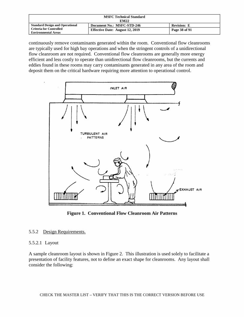
MSFC Technical Standard EM22
Standard Design and Operational Criteria for Controlled Environmental Areas
Document No.: MSFC-STD-246 Revision: E Effective Date: August 12, 2019 Page 38 of 91
CHECK THE MASTER LIST – VERIFY THAT THIS IS THE CORRECT VERSION BEFORE USE
continuously remove contaminants generated within the room. Conventional flow cleanrooms are typically used for high bay operations and when the stringent controls of a unidirectional flow cleanroom are not required. Conventional flow cleanrooms are generally more energy efficient and less costly to operate than unidirectional flow cleanrooms, but the currents and eddies found in these rooms may carry contaminants generated in any area of the room and deposit them on the critical hardware requiring more attention to operational control.
Figure 1. Conventional Flow Cleanroom Air Patterns
5.5.2 Design Requirements. 5.5.2.1 Layout A sample cleanroom layout is shown in Figure 2. This illustration is used solely to facilitate a presentation of facility features, not to define an exact shape for cleanrooms. Any layout shall consider the following:
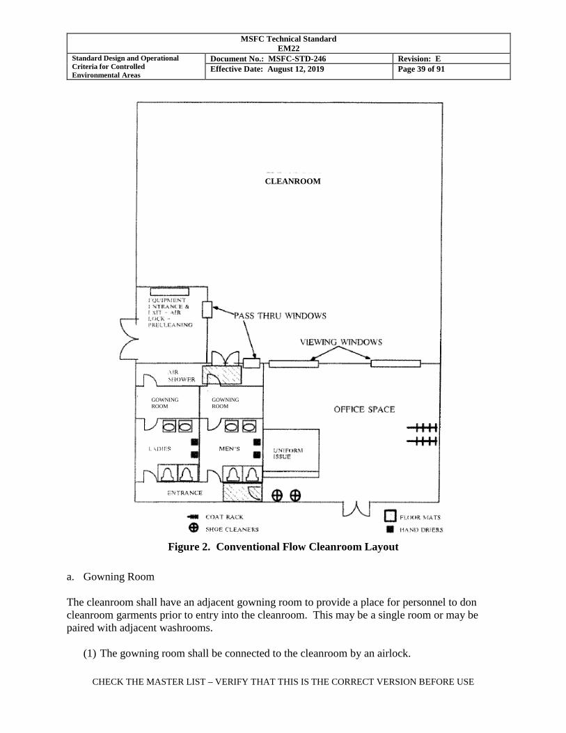
MSFC Technical Standard EM22
Standard Design and Operational Criteria for Controlled Environmental Areas
Document No.: MSFC-STD-246 Revision: E Effective Date: August 12, 2019 Page 39 of 91
CHECK THE MASTER LIST – VERIFY THAT THIS IS THE CORRECT VERSION BEFORE USE
Figure 2. Conventional Flow Cleanroom Layout
a. Gowning Room The cleanroom shall have an adjacent gowning room to provide a place for personnel to don cleanroom garments prior to entry into the cleanroom. This may be a single room or may be paired with adjacent washrooms.
(1) The gowning room shall be connected to the cleanroom by an airlock.
GOWNING ROOM
GOWNING ROOM
CLEANROOM
MSFC Technical Standard EM22
Standard Design and Operational Criteria for Controlled Environmental Areas
Document No.: MSFC-STD-246 Revision: E Effective Date: August 12, 2019 Page 40 of 91
CHECK THE MASTER LIST – VERIFY THAT THIS IS THE CORRECT VERSION BEFORE USE
(2) The gowning room shall receive clean filtered air equivalent to that supplied to the cleanroom.
(3) The gowning room shall be furnished with a cabinet or wall-mounted rack for hanging cleanroom garments to be re-used, a bench for donning shoe covers, a full length mirror for self-inspection of donned garments, and bins for the collection of garments to be laundered (if used) and for waste.
(4) A vacuum shoe cleaner shall be provided just outside the entrance to the gowning room. The vacuum may exhaust via a central vacuum system port or an attached HEPA filter.
(5) Sticky mats shall be located between the gowning room and entrance to the cleanroom.
(6) Personal lockers and coat racks for the storage of notebooks, coats, and personal items shall be located in the uncontrolled area outside of the gowning room.
(7) Washrooms (optional) may be located at or near the entrance to the gowning room for convenience.
b. Airlock/Air Shower The cleanroom shall have an airlock for personnel entry from the gowning room into the cleanroom.
(1) The cleanliness of the airlock air supply shall be the same as the cleanroom.
(2) The airlock shall include interlocks that preclude opening both doors at the same time.
(3) When a full coverall uniform is required, the airlock shall include an integral air shower system to remove particulate adhering to the wearer's garment.
(4) When an air shower is used, a separate airlock exit may be provided from the cleanroom into the gowning room. This may be useful for high occupancy rooms to reduce traffic backups at shift change. If used, this door should have a one-way lock to prevent personnel who are entering from bypassing the air shower.
c. Equipment Airlock An equipment airlock shall be provided to accommodate equipment that must be moved into or out of cleanroom. This airlock will also serve as the location where final cleaning operations are performed on equipment prior to delivery into the cleanroom. The equipment airlock for a high bay cleanroom will also be a high bay.
MSFC Technical Standard EM22
Standard Design and Operational Criteria for Controlled Environmental Areas
Document No.: MSFC-STD-246 Revision: E Effective Date: August 12, 2019 Page 41 of 91
CHECK THE MASTER LIST – VERIFY THAT THIS IS THE CORRECT VERSION BEFORE USE
(1) This airlock shall be sized to accommodate carts, shipping containers, support equipment, and other items expected to be transported in and out of the cleanroom during the normal course of business. For very large facilities such as high bays, a separate transport airlock and a smaller equipment airlock for hand carts are recommended.
(2) This airlock shall be constructed with the same clean air source and using materials and features similar to those of the cleanroom but may include floor drains and other features not normally found inside cleanrooms.
(3) Equipment airlock doors may be swinging doors, sliding panel doors, or roll-up doors. Airlock doors should include pressure seals and interlocks to maintain pressure inside the cleanroom.
(4) For large, infrequently moved items such as major tooling, temporary airlocks may be constructed of polyethylene or similar approved plastic sheeting.
d. Pass-through Windows Pass-through windows or pass-through boxes are small airlocks through which hand tools or small parts can be transferred in or out of a cleanroom without carrying them through the larger airlocks. Pass-through windows are recommended as they will help minimize personnel traffic in and out, thus minimizing cleanroom contamination.
e. Viewing windows Windows between the cleanroom and the surrounding uncontrolled area, where visitors may view operations without entering the cleanroom, are recommended. To facilitate lighting requirements for ultraviolet inspection (if required) the viewing window should have shutters or include a powered screen outside of the cleanroom enclosure. (The screen may be between the panes of glass.) f. Central Vacuum System A central vacuum system, with vacuum ports distributed around the facility and exhausting outside the clean facility, is recommended. When a central vacuum system is to be installed, consideration should be given to installation of a port for the vacuum shoe cleaner(s). g. Communication Systems Two-way communication systems shall be provided at convenient locations such as viewing windows, pass-through windows, and airlocks to minimize the need for non-essential personnel to enter the cleanroom or speak through an open door to communicate with personnel inside the cleanroom.

MSFC Technical Standard EM22
Standard Design and Operational Criteria for Controlled Environmental Areas
Document No.: MSFC-STD-246 Revision: E Effective Date: August 12, 2019 Page 42 of 91
CHECK THE MASTER LIST – VERIFY THAT THIS IS THE CORRECT VERSION BEFORE USE
5.5.2.2 Environmental Conditions Environmental conditions for conventional flow cleanrooms are specified in Table I. a. HVAC System
(1) The HVAC system may be a standard commercial design except that the filtration system shall have three stages in accordance with section 5.1.1, a pre-filter, a medium efficiency filter and a final HEPA filter.
(2) HEPA filters may be installed either in the ceiling at the inlet to the cleanroom or in a distribution plenum outside the cleanroom with diffuser registers located at the point of air entry to the cleanroom. A distribution plenum is typically used in large aerospace cleanrooms.
(3) All air return outlets shall be located low on the walls, as close as possible to the floor to minimize updrafts that could carry contaminants from the floor onto hardware surfaces.
(4) Ceiling air supply registers and low wall air return outlets shall be evenly distributed around the room to minimize dead zones.
b. Air Changes
(1) The HVAC system for a Class 8 cleanroom shall be designed to provide at least 15 air changes per hour. Higher air changes per hour may be required to accommodate higher personnel occupancy or to shorten recovery time from contamination upset events.
(2) The HVAC system for a Class 7 conventional flow cleanroom shall be designed to provide at least 20 air changes per hour. Higher air changes per hour may be required to accommodate higher personnel occupancy or to shorten recovery time from contamination upset events.
c. Airborne Particle Concentration
The airborne particle concentration for Class 8 and Class 7 shall be certified in the operational condition when tested in accordance with section 5.9.
d. A minimum pressure differential of 12.5 Pa (0.05 inches of water) shall be maintained at all times to prevent contaminated air from flowing into the cleanroom. Where cleanrooms of varying levels of cleanliness are joined as one complex, the cleaner room should be maintained at a slight positive pressure over the next less-clean room.
MSFC Technical Standard EM22
Standard Design and Operational Criteria for Controlled Environmental Areas
Document No.: MSFC-STD-246 Revision: E Effective Date: August 12, 2019 Page 43 of 91
CHECK THE MASTER LIST – VERIFY THAT THIS IS THE CORRECT VERSION BEFORE USE
NOTE: When hazardous materials, such as some propellants, are being processed, it may be necessary to maintain the room at a lower pressure than the surrounding rooms to assure containment. In such special cases, this is acceptable. e. Temperature and humidity requirements are as follows:
(1) Temperature and humidity controls shall prevent condensation on hardware and maintain worker comfort, as a minimum.
(2) Temperature shall be 19 to 25oC (67 to 77°F), unless otherwise specified in the Operating Procedure. A lower range of 16-22oC (62-72°F) is permitted and should be considered for worker comfort when coveralls are required.
(3) Relative humidity shall be 30 to 50%. The lower limit may be relaxed when electrostatic control is not required; however, a lower humidity limit of 25-30% is recommended to prevent electrostatic attraction of particles to packaging films and other non-conducting surfaces.
(4) If the cleanroom incorporates flow benches, clean tents, or other clean air devices, then more stringent limits for temperature and humidity within the cleanroom may be required to satisfy requirements for the operations to be performed within the localized environment(s).
f. Lighting To facilitate visual detection of contamination and cleaning, the facility should provide a general lighting level of 750-860 lux (70-80 foot candles) on all surfaces. Lighting at work locations where highly contamination sensitive hardware is processed should be approximately 1100 lux (100 foot candles). Localized illumination may be provided by task lighting. If ultraviolet inspection of hardware is to be accommodated, lighting design should include the capability to dim or switch off the main lighting, retaining background lighting of 11-22 lux (1-2 footcandles) for safety. 5.5.3 Operations. 5.5.3.1 Clothing Requirements a. In Class 8 cleanrooms, personnel shall wear cleanroom frocks and hair covers as a minimum. Shoe covers or booties are recommended. When frocks are required, full coverage uniforms (coveralls, hoods, and booties) should be considered for use in critical zones such as on elevated stands over hardware. In rooms with high occupancy or activity levels, coveralls may be required to maintain airborne particulate levels and to limit transfer of fibers to the hardware. b. In Class 7 cleanrooms, personnel shall wear coveralls, hoods, and booties.
MSFC Technical Standard EM22
Standard Design and Operational Criteria for Controlled Environmental Areas
Document No.: MSFC-STD-246 Revision: E Effective Date: August 12, 2019 Page 44 of 91
CHECK THE MASTER LIST – VERIFY THAT THIS IS THE CORRECT VERSION BEFORE USE
c. Personnel shall wear approved gloves when handling contamination sensitive hardware. Gloves may be required for everyone in the facility, depending on end item requirements and type of work being performed. 5.5.3.2 Entry and Exit Procedures a. The following procedures shall apply for entry of personnel into cleanrooms:
(1) Before entering the gowning room from an environmentally uncontrolled area, remove outer garments such as raincoats, overcoats, ball caps, etc. and unnecessary items such as jewelry.
(2) Clean shoes with the vacuum shoe cleaner provided at the entrance to the gowning room. A visual check should be made to ensure that caked contaminants such as mud, dirt, sand, salt, cement, etc., have been removed.
(3) Select the cleanroom garments as specified per the facility Operating Procedure.
(4) Inspect the garments for holes, tears, missing snaps, and other defects. Turn in any damaged items for replacement with an undamaged garment.
(5) Don garments from the head down, using care to minimize contamination. Garments should not be allowed to contact the floor. Typical gowning for a full coverall uniform is as follows:
A. Don the hood including face mask or facial hair cover when required. The hood yoke
is worn tucked into the coveralls collar. Fasten snaps and laces for a snug fit around the face.
B. Don coveralls, taking care not to drag the garment arms or legs on the floor. Fully fastened and close all snaps and zippers.
C. Don booties. Coverall legs are tucked into booties. Tape may be used with disposable garments to secure booties to the coverall or for a more secure fit. Tape use on reusable garments should be approved by the CCE.
(6) Enter the room through the airlock/air shower, walking across the sticky mat. b. The following procedures shall apply for exit of personnel from cleanrooms:
(1) Upon leaving the cleanroom, remove cleanroom garments in reverse order of donning, being careful not to allow garments that will be worn again to contact the floor.
MSFC Technical Standard EM22
Standard Design and Operational Criteria for Controlled Environmental Areas
Document No.: MSFC-STD-246 Revision: E Effective Date: August 12, 2019 Page 45 of 91
CHECK THE MASTER LIST – VERIFY THAT THIS IS THE CORRECT VERSION BEFORE USE
(2) Store garments to be worn again in an enclosed area. When enclosed garment cabinets or racks are not provided, garments should be folded, enclosed in plastic bags, labeled with the user’s name, and placed on a shelf. Cleanroom shoes or shoe covers should be handled similarly and placed in separate plastic bags.
(3) Discard one-use garment pieces (e.g. gloves, disposable shoe covers). c. The following procedures shall apply for entry of Parts, Tools, Equipment, and Materials:
(1) All parts, tools, equipment, and material brought into the cleanroom shall be approved by
the Custodian for compatibility with the cleanliness requirements of that cleanroom. Items that do not meet the cleanliness criteria may be permitted when properly packaged or otherwise controlled to minimize the risk of contamination of the facility or sensitive hardware.
(2) Prior to entry into a cleanroom, all parts, tools, equipment, and material shall be cleaned. This cleaning may be performed in an equipment airlock. Cleaning may also be performed in a remote location, with the item covered or packaged to maintain cleanliness during transfer to the cleanroom. Selection of cleaning solvents and methods will depend on type of contaminant, materials of construction, and degree of cleanliness required.
(3) Large items of equipment shall be brought into a cleanroom as follows: A. Perform rough cleaning, if needed to remove gross dust, mud, or road debris, in an
uncontrolled area outside of the cleanroom complex.
B. Final clean the item inside the equipment airlock (or temporary airlock) by vacuum and wiping until the item is visibly clean when inspected at 2-3 feet. The airlock should also be cleaned as needed prior to opening the inner door to the cleanroom.
C. If the large item has been delivered clean and double bagged, the outer hard cover (if used) and outer bag should be removed in the airlock and the inner bag removed inside the cleanroom. This sequence may not be feasible if the item must be lifted by crane.
D. Cleanroom operations should be suspended and sensitive hardware covered while the large item is moved from the airlock into the cleanroom.
(4) Hand tools used in the cleanroom shall be cleaned prior to entry and at scheduled
intervals. The facility Custodian shall determine the required cleaning schedule.
MSFC Technical Standard EM22
Standard Design and Operational Criteria for Controlled Environmental Areas
Document No.: MSFC-STD-246 Revision: E Effective Date: August 12, 2019 Page 46 of 91
CHECK THE MASTER LIST – VERIFY THAT THIS IS THE CORRECT VERSION BEFORE USE
(5) General parts cleaning shall occur outside of the cleanroom (except for precision cleaning of parts performed in cleanrooms designed for that purpose). Pass-through boxes should be used to transfer small parts into cleanrooms.
(6) Hardware that is very cold (below the dew point) should be allowed to acclimate to
cleanroom temperature prior to entry to avoid condensation. 5.5.3.3 Material and Parts Handling inside the Cleanroom a. Tote boxes, packaging materials, plastic curtains, draping films, and other support materials to be used in the cleanroom shall be smooth, cleanable, and non-shedding. In cleanrooms that are sensitive to NVR, plastic items should be tested for contact transfer or outgassing at ambient temperature to assure that they will not be a contamination source. b. Parts that are sensitive to contamination shall always be handled with tools or gloved hands. For most applications, clean, powder-free latex or nitrile gloves or finger cots will be sufficient. Low-linting, tightly woven cloth gloves may be acceptable; however, these gloves will not protect the hardware from hand perspiration and associated hand oils and salts. Cloth gloves should be used only when the properties of a cloth glove (such as grip and tear resistance) are required and hand perspiration is limited or controlled. Cloth gloves may be laundered for reuse. Reference section 4.4.5.2 for guidance on glove selection. c. Any item left exposed for a sufficient period of time, in any class of clean facility, will become contaminated due to general fallout. When not in use, parts, tools, equipment, and materials shall be draped with clean film, packaged, stored in clean tote boxes, or subject to routine inspection and re-cleaning. 5.5.3.4 Cleaning of Cleanrooms. In addition to the requirements and guidelines noted in section 4.4.4, the following items should be considered when procedures for cleaning the cleanroom are established: a. Facility cleaning activities will temporarily increase contamination levels in the room. Cleaning should be done during non-critical activities, preferably during late day or night. Sensitive hardware should be protected with an approved material or cover during cleaning operations. b. Cellulose mops and sponges, or other non-shedding materials, shall be used with clean water. High-grade plastic buckets and other equipment should be selected that are not subject to flaking. A dilute, clean-rinsing, water-soluble non-ionic detergent may be used in most cleanrooms on floors, walls, and other facility surfaces. When detergent is not permitted, isopropyl alcohol is typically used for cleanroom cleaning. c. Tacky rollers may be used on perforated floors, walls, and other smooth surfaces.
MSFC Technical Standard EM22
Standard Design and Operational Criteria for Controlled Environmental Areas
Document No.: MSFC-STD-246 Revision: E Effective Date: August 12, 2019 Page 47 of 91
CHECK THE MASTER LIST – VERIFY THAT THIS IS THE CORRECT VERSION BEFORE USE
d. A central vacuum cleaning system or a portable vacuum cleaner with a HEPA filtered exhaust shall be employed for cleaning. Minor dry floor and bench vacuuming may be performed, if necessary, during room operations if equipment and procedures used ensure a minimum of disturbance to settled particles. e. Floors shall not be waxed. Acrylic floor coatings used for static dissipation may be permitted in Class 8 cleanrooms and CWAs but should be avoided in Class 7 and cleaner facilities as they wear with time and require periodic reapplication. f. Housekeeping equipment stored outside of the clean facility shall be thoroughly cleaned prior to entering the cleanroom. Housekeeping equipment used to clean cleanrooms shall not be used to clean less clean facilities. 5.5.4 Monitoring. 5.5.4.1 Particulate shall be monitored continuously during operations. This may be accomplished using a portable discreet particle counter instrument or an installed remote sensor system. For a more accurate representation of the working environment, the particle counter should be located close to the hardware operations. 5.5.4.2 Temperature and humidity shall be monitored at all times. Many automatic particle counter instruments are available with integral temperature and humidity sensors. 5.5.4.3 Conventional flow cleanrooms shall be periodically sampled in accordance with section 5.9 and recorded at least once a week for particle count, temperature, humidity, and pressure as specified in Table I. 5.5.4.5 Periodic sampling of particulate, and hydrocarbons when required, shall be performed in the immediate vicinity of the hardware in processing areas during normal operating conditions to ensure a representative sampling of the operational environment. 5.6 Unidirectional Flow Cleanrooms. 5.6.1 General Description. A unidirectional flow cleanroom (formerly referred to as laminar flow) is designed to provide airflow that is essentially unidirectional. As shown in Figure 3, parallel air streams flow from the HEPA filter face to the exhaust grills, continuously sweeping generated contaminants away from the work surface and into the air return ducts. Unidirectional flow cleanrooms are preferred when a higher cleanliness level is required or the hardware must remain uncovered for an extended period. Unidirectional flow cleanrooms are classified as cross-flow or down-flow and are capable of achieving Class 5 when unoccupied and maintaining Classes 5 through 7 during operations with stringent operational controls. The Class that the cleanroom can maintain is determined by the total load of personnel and particulate-generating operations to be

MSFC Technical Standard EM22
Standard Design and Operational Criteria for Controlled Environmental Areas
Document No.: MSFC-STD-246 Revision: E Effective Date: August 12, 2019 Page 48 of 91
CHECK THE MASTER LIST – VERIFY THAT THIS IS THE CORRECT VERSION BEFORE USE
accommodated. Cleanliness levels cleaner than Class 5 may be achieved with the use of Ultra-Low Penetration Air (ULPA) filters (reference IEST-RP-CC001) in place of HEPA filters and very stringent operational controls.
Figure 3. Unidirectional Flow Cleanroom Air Patterns
5.6.1.1 Types There are two types of unidirectional flow cleanroom: a. Unidirectional Cross-Flow. When airflow is horizontal, flowing in parallel lines from one wall to an opposite exit wall, the facility is called a unidirectional cross-flow cleanroom. A typical cross-flow cleanroom is shown in Figure 4. The most sensitive hardware is placed in front of the wall of HEPA filters with no obstructions in between to disturb the airflow. Less sensitive hardware and operations are placed downstream of the most sensitive hardware, where the air is less clean. A large item of hardware placed near the filter wall will disturb the air flow pattern, resulting in a downstream condition that is less than fully unidirectional.
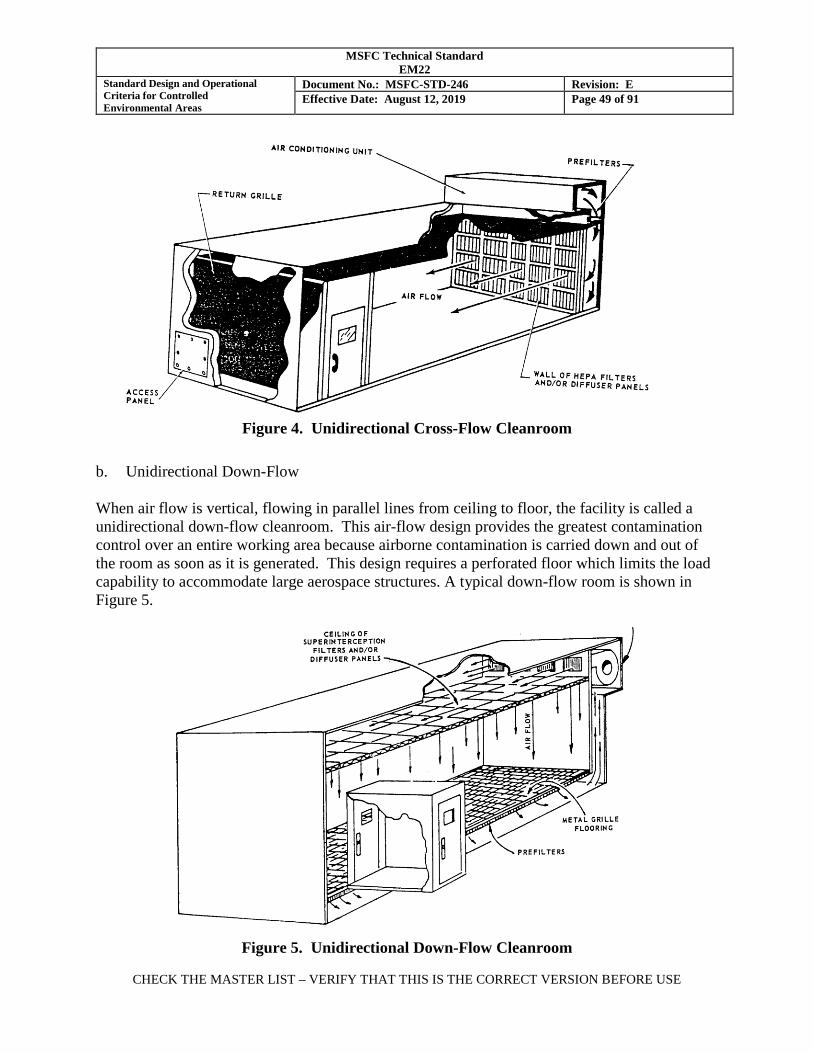
MSFC Technical Standard EM22
Standard Design and Operational Criteria for Controlled Environmental Areas
Document No.: MSFC-STD-246 Revision: E Effective Date: August 12, 2019 Page 49 of 91
CHECK THE MASTER LIST – VERIFY THAT THIS IS THE CORRECT VERSION BEFORE USE
Figure 4. Unidirectional Cross-Flow Cleanroom
b. Unidirectional Down-Flow When air flow is vertical, flowing in parallel lines from ceiling to floor, the facility is called a unidirectional down-flow cleanroom. This air-flow design provides the greatest contamination control over an entire working area because airborne contamination is carried down and out of the room as soon as it is generated. This design requires a perforated floor which limits the load capability to accommodate large aerospace structures. A typical down-flow room is shown in Figure 5.
Figure 5. Unidirectional Down-Flow Cleanroom
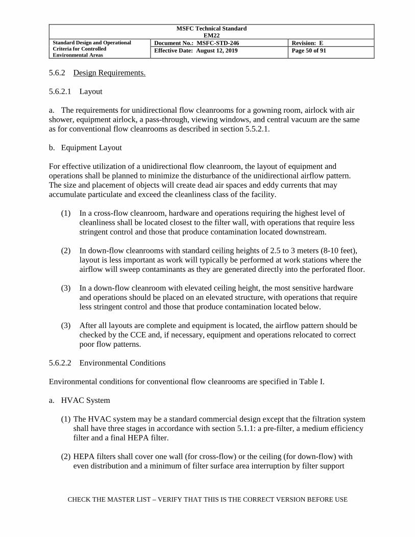
MSFC Technical Standard EM22
Standard Design and Operational Criteria for Controlled Environmental Areas
Document No.: MSFC-STD-246 Revision: E Effective Date: August 12, 2019 Page 50 of 91
CHECK THE MASTER LIST – VERIFY THAT THIS IS THE CORRECT VERSION BEFORE USE
5.6.2 Design Requirements. 5.6.2.1 Layout a. The requirements for unidirectional flow cleanrooms for a gowning room, airlock with air shower, equipment airlock, a pass-through, viewing windows, and central vacuum are the same as for conventional flow cleanrooms as described in section 5.5.2.1. b. Equipment Layout For effective utilization of a unidirectional flow cleanroom, the layout of equipment and operations shall be planned to minimize the disturbance of the unidirectional airflow pattern. The size and placement of objects will create dead air spaces and eddy currents that may accumulate particulate and exceed the cleanliness class of the facility. (1) In a cross-flow cleanroom, hardware and operations requiring the highest level of
cleanliness shall be located closest to the filter wall, with operations that require less stringent control and those that produce contamination located downstream.
(2) In down-flow cleanrooms with standard ceiling heights of 2.5 to 3 meters (8-10 feet),
layout is less important as work will typically be performed at work stations where the airflow will sweep contaminants as they are generated directly into the perforated floor.
(3) In a down-flow cleanroom with elevated ceiling height, the most sensitive hardware
and operations should be placed on an elevated structure, with operations that require less stringent control and those that produce contamination located below.
(3) After all layouts are complete and equipment is located, the airflow pattern should be
checked by the CCE and, if necessary, equipment and operations relocated to correct poor flow patterns.
5.6.2.2 Environmental Conditions Environmental conditions for conventional flow cleanrooms are specified in Table I. a. HVAC System
(1) The HVAC system may be a standard commercial design except that the filtration system shall have three stages in accordance with section 5.1.1: a pre-filter, a medium efficiency filter and a final HEPA filter.
(2) HEPA filters shall cover one wall (for cross-flow) or the ceiling (for down-flow) with even distribution and a minimum of filter surface area interruption by filter support
MSFC Technical Standard EM22
Standard Design and Operational Criteria for Controlled Environmental Areas
Document No.: MSFC-STD-246 Revision: E Effective Date: August 12, 2019 Page 51 of 91
CHECK THE MASTER LIST – VERIFY THAT THIS IS THE CORRECT VERSION BEFORE USE
structures, lighting fixtures, and other installations. Filter coverage of 80% of the surface or more is generally required to obtain unidirectional flow.
(3) Air return shall be through a perforated wall opposite the filter wall (for cross-flow) or a perforated floor (for down-flow).
(4) The HVAC system shall be balanced to achieve uniform flow throughout the unoccupied room at the required temperature, humidity, air velocity, and pressure conditions.
b. Filter Face Velocity
(1) The air velocity at the face of the HEPA filters shall be 0.46 to 0.56 m/sec (90 to 110 ft/min) at initial certification of the cleanroom.
(2) The filter face velocities shall be balanced to within +/- 10% to achieve effective uniform, unidirectional airflow.
(3) The air change rate for unidirectional flow cleanrooms is determined by the filter face velocity and the size of the room and is therefore not specified as a design requirement for the room.
c. Airborne Particle Concentration The airborne particle concentration for Class 8, Class 7, Class 6 and Class 5 shall be certified in the operational condition when tested in accordance with section 5.9.
d. A minimum pressure differential of 12.5 Pa (0.05 inches of water) shall be maintained at all times to prevent contaminated air from flowing into the cleanroom.
NOTE: When hazardous materials, such as some propellants, are being processed, it may be necessary to maintain the room at a lower pressure than the surrounding rooms to assure containment. In such special cases, this is acceptable.
e. Temperature and humidity requirements are the same as for conventional flow cleanrooms.
f. Lighting
(1) To facilitate visual detection of contamination and cleaning, the facility should provide a
general lighting level of 750-860 lux (70-80 foot-candles) on all surfaces.
(2) Facility lighting shall be flush-mounted to minimize disruption of airflow.
MSFC Technical Standard EM22
Standard Design and Operational Criteria for Controlled Environmental Areas
Document No.: MSFC-STD-246 Revision: E Effective Date: August 12, 2019 Page 52 of 91
CHECK THE MASTER LIST – VERIFY THAT THIS IS THE CORRECT VERSION BEFORE USE
(3) Lighting at work locations where highly contamination sensitive hardware is processed should be approximately 1100 lux (100 foot candles). This localized illumination may be provided by task lighting.
(4) If ultraviolet inspection of hardware is to be accommodated, lighting design should include the capability to dim or switch off the main lighting, retaining background lighting of 11-22 lux (1-2 foot candles) for safety.
5.6.3 Operations. 5.6.3.1 Clothing Requirements a. In Class 8 down-flow cleanrooms with standard ceiling height, personnel shall wear cleanroom frocks and hair covers as a minimum. b. In Class 8 down-flow cleanrooms with elevated ceiling height and work positioned on elevated stands, full coverage uniforms (coveralls, hoods, and booties) shall be worn on the elevated stands. c. In Class 7 cleanrooms, personnel shall wear coveralls, hoods, and booties. d. In Class 8 and Class 7 cleanrooms, personnel shall wear approved gloves when handling contamination sensitive hardware. Gloves may be required for everyone in the facility, depending on end item requirements and type of work being performed. e. In Class 6 and Class 5 cleanrooms, personnel shall wear coveralls, hoods, booties, and gloves. Face masks may be required.
5.6.3.2 Entry and exit procedures shall be the same as for conventional flow cleanrooms. 5.6.3.3 Material and parts handling procedures shall be the same as for conventional flow cleanrooms. 5.6.3.4 Requirements and guidelines for cleaning of unidirectional cleanrooms shall be the same as for conventional flow cleanrooms. 5.6.4 Monitoring. 5.6.4.1 Monitoring and periodic sampling of particulates, temperature, humidity, and pressure shall be the same as for conventional flow cleanrooms 5.6.4.2 In cross-flow cleanrooms, particulate levels downstream of hardware operations and personnel activity are expected to be higher than upstream. Airborne particle counts near the exit wall may be permitted to exceed the particle limits for the facility during operations.
MSFC Technical Standard EM22
Standard Design and Operational Criteria for Controlled Environmental Areas
Document No.: MSFC-STD-246 Revision: E Effective Date: August 12, 2019 Page 53 of 91
CHECK THE MASTER LIST – VERIFY THAT THIS IS THE CORRECT VERSION BEFORE USE
5.6.4.3 Room airflow velocity shall be periodically checked for compliance with the requirements specified in Table I. a. Airflow velocity shall not vary more than 0.1 m/sec (20 ft/min or +/- 10 ft/min) throughout the cleanroom. b. Airflow velocity in cross-flow cleanrooms shall not drop below .38 m/sec (75 ft/min) at work locations. In down-flow cleanrooms, the Custodian may specify a lower limit of 0.25 m/sec (50 ft/min) at the work height when a higher air flow velocity would disturb the work. c. Routine or periodic measurement of airflow velocity at the filter face is often impractical due to the location of the HEPA filters. After initial certification of the facility, measurement of airflow velocity at the filter face should be not be necessary unless a deficiency in the filters or HVAC system is suspected. 5.7 Unidirectional Flow Bench/Clean Work Station. 5.7.1 General Description. Unidirectional (laminar) flow benches offer a high degree of flexibility at low cost for operations requiring cleanliness that can be performed within a localized, tabletop setting. In such situations the ambient contamination level of the room may be very high in comparison to the environment within the flow bench workstation. The unidirectional flow bench operates by blowing clean air from HEPA filters over the work area at a constant velocity of approximately 0.45 m/sec (90 ft/min), removing contamination from the workspace as soon as it is generated. Unidirectional flow benches are available as off-the-shelf modular units. Reference IEST-RP-CC002, “Unidirectional Flow Clean Air Devices”, for guidance in the specification and procurement of these devices. 5.7.1.1 Cleanliness Class HEPA-filtered unidirectional flow benches are designed to achieve Class 5 cleanliness, but they may also be used to maintain a lesser cleanliness class. If a flow bench is used to maintain a condition less clean than Class 5, then it shall be labeled for that class and be monitored for the higher particulate concentration. 5.7.1.2 Types The size and shape of the flow bench may vary depending on the type of work being performed. The flow of air may be horizontal or vertical as long as it is essentially unidirectional and achieves the cleanliness level desired. Both floor mounted and tabletop units are available. Basic configurations are as follows: a. Horizontal Flow Bench
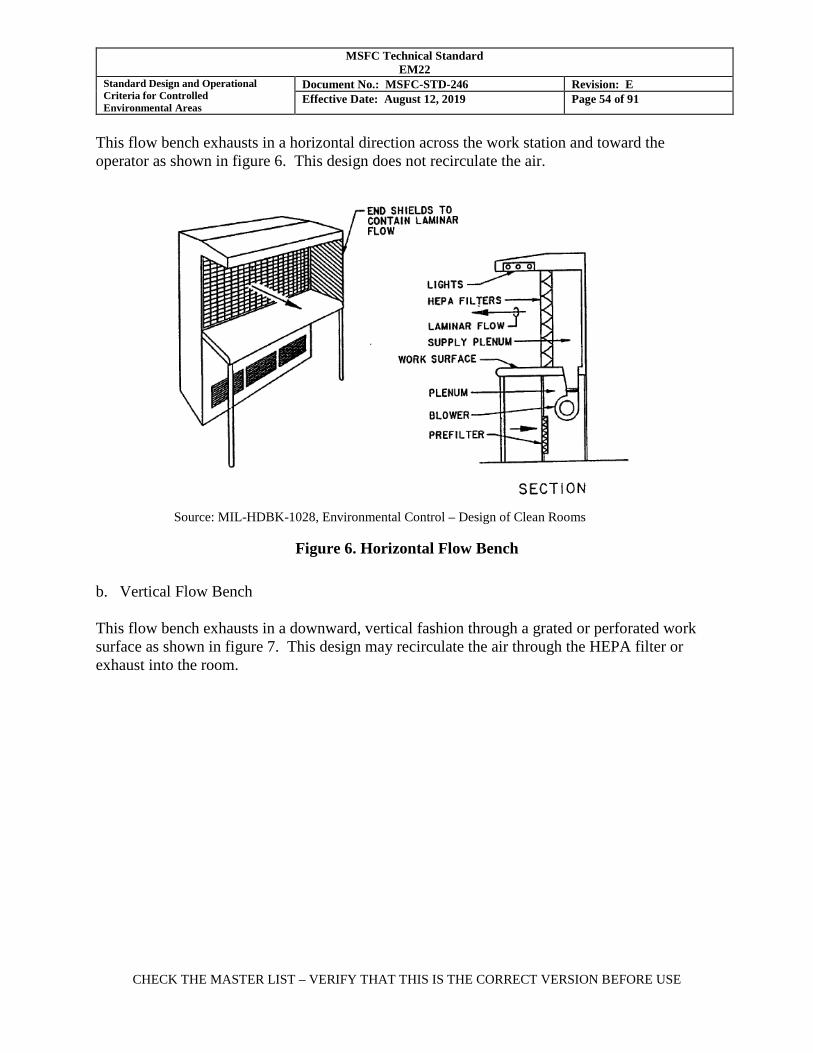
MSFC Technical Standard EM22
Standard Design and Operational Criteria for Controlled Environmental Areas
Document No.: MSFC-STD-246 Revision: E Effective Date: August 12, 2019 Page 54 of 91
CHECK THE MASTER LIST – VERIFY THAT THIS IS THE CORRECT VERSION BEFORE USE
This flow bench exhausts in a horizontal direction across the work station and toward the operator as shown in figure 6. This design does not recirculate the air.
Figure 6. Horizontal Flow Bench
b. Vertical Flow Bench This flow bench exhausts in a downward, vertical fashion through a grated or perforated work surface as shown in figure 7. This design may recirculate the air through the HEPA filter or exhaust into the room.
Source: MIL-HDBK-1028, Environmental Control – Design of Clean Rooms
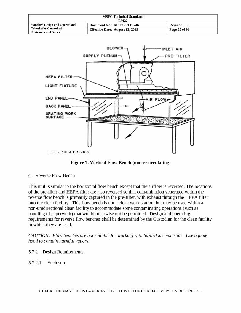
MSFC Technical Standard EM22
Standard Design and Operational Criteria for Controlled Environmental Areas
Document No.: MSFC-STD-246 Revision: E Effective Date: August 12, 2019 Page 55 of 91
CHECK THE MASTER LIST – VERIFY THAT THIS IS THE CORRECT VERSION BEFORE USE
Figure 7. Vertical Flow Bench (non-recirculating)
c. Reverse Flow Bench This unit is similar to the horizontal flow bench except that the airflow is reversed. The locations of the pre-filter and HEPA filter are also reversed so that contamination generated within the reverse flow bench is primarily captured in the pre-filter, with exhaust through the HEPA filter into the clean facility. This flow bench is not a clean work station, but may be used within a non-unidirectional clean facility to accommodate some contaminating operations (such as handling of paperwork) that would otherwise not be permitted. Design and operating requirements for reverse flow benches shall be determined by the Custodian for the clean facility in which they are used. CAUTION: Flow benches are not suitable for working with hazardous materials. Use a fume hood to contain harmful vapors. 5.7.2 Design Requirements. 5.7.2.1 Enclosure
Source: MIL-HDBK-1028
MSFC Technical Standard EM22
Standard Design and Operational Criteria for Controlled Environmental Areas
Document No.: MSFC-STD-246 Revision: E Effective Date: August 12, 2019 Page 56 of 91
CHECK THE MASTER LIST – VERIFY THAT THIS IS THE CORRECT VERSION BEFORE USE
a. The flow bench enclosure surfaces shall be constructed of smooth, durable materials that are not susceptible to corrosion or particle shedding and is easily wiped clean, e.g., acrylic, plastic laminate, epoxy-painted steel, or stainless steel. b. All flow benches shall include side panels to contain unidirectional flow throughout the work zone. A clear plastic drape or partial panel is recommended at the front of a vertical flow bench to help maintain unidirectional flow throughout the work zone. c. The continuous air flow within a flow bench will tend to generate an electrostatic charge on some surfaces. Flow benches that will be used to process components that are susceptible to electrostatic discharge shall be designed with accommodations for electrostatic discharge control. Reference ANSI/ESD S20.20. 5.7.2.2 Airborne Particle Concentration a. Airborne particle concentration shall meet Class 5 , no more than 3520 particles per cubic meter (100 particles per cubic foot) of air 0.5 μm and larger, except where the Custodian specifies a less clean rating.
b. This condition shall prevail throughout the entire workbench 5.7.2.3 Filters The final filters shall be HEPA filters sealed within the unit. Pre-filters will extend the life of the HEPA filters and should be selected based on the cleanliness of the facility in which the flow bench will be operated. NOTE: Ultra Low Penetration Air (ULPA) filters, with a particle collection efficiency of 99.999% in accordance with IEST-RP-CC001, may be used to achieve cleanliness levels cleaner than Class 5 (100). 5.7.2.4 Airflow Velocity a. The unidirectional flow bench shall be designed to maintain a uniform airflow velocity of 0.45 m/sec (90 ft/min) throughout the flow bench work area.
b. Uniformity of air flow velocity shall be within +/- 0.05 m/sec (+/- 10 ft/min).
c. The airflow shall be unidirectional in a path perpendicular to the HEPA filter face. 5.7.2.5 Lighting
MSFC Technical Standard EM22
Standard Design and Operational Criteria for Controlled Environmental Areas
Document No.: MSFC-STD-246 Revision: E Effective Date: August 12, 2019 Page 57 of 91
CHECK THE MASTER LIST – VERIFY THAT THIS IS THE CORRECT VERSION BEFORE USE
Shadow-less illumination with a minimum intensity of 1100 lux (100 foot candles) is recommended at the work surface. Precautions should be taken to avoid glare and excessive illumination. 5.7.3 Placement of Flow Bench 5.7.3.1 Temperature and Humidity Flow benches do not provide for control of temperature or humidity. The flow bench shall be located within a facility that provides sufficient temperature and humidity control for the operations to be performed on the flow bench. 5.7.3.2 Air Disturbances Unidirectional flow benches are designed to operate within controlled indoor environments such as laboratories. If a flow bench is placed in a wind condition of .025 m/sec (50 ft/min or 0.5 miles per hour) or more (e.g., outdoors or in a high traffic production environment), windborne contamination will be forced into the device, defeating its design purpose. Under some circumstances, a wind shelter surrounding the device may be required to ensure that the controlled environment can be maintained. 5.7.3.3 Grouping within a Larger Clean Zone Flow benches may be placed as a group in an existing clean facility or an air-conditioned room. Such a layout may use the recirculation capacity of the benches to clean the room air. A room of standard height utilizing 20 percent of its floor area with flow benches can expect approximately 100 room air changes per hour through the flow bench HEPA filters. If the air supply to the room also passes through HEPA filters, the recirculation and filtration of air through the flow benches will cause the room contamination level to approach that of Class 5. If the air supply to the room does not pass through HEPA filters, the room contamination level may achieve Class 8 or better. 5.7.3.4 Use in cleanrooms Flow benches should not be placed within unidirectional flow cleanrooms as they will disturb the airflow patterns in the room. Flow benches are acceptable in conventional flow cleanrooms. 5.7.3.5 Use near contaminating operations Flow benches should not be located in an area where heavy particles are distributed by other operations such as machining. Heavy particles may penetrate the air stream or follow a worker's arms into the flow bench and degrade its effectiveness. When such a location is necessary, preventive measures shall be used such as installing a protective shield or extending the top of the flow bench to protect that area from heavy fallout sources.
MSFC Technical Standard EM22
Standard Design and Operational Criteria for Controlled Environmental Areas
Document No.: MSFC-STD-246 Revision: E Effective Date: August 12, 2019 Page 58 of 91
CHECK THE MASTER LIST – VERIFY THAT THIS IS THE CORRECT VERSION BEFORE USE
5.7.4 Operation of Unidirectional Flow Benches 5.7.4.1 Clothing Requirements a. Personnel performing operations on flow benches that are located within a controlled clean facility shall wear the garments required for that facility as a minimum. b. Frocks with snug fitting wrist closures are recommended when the flow bench is located outside of a controlled clean facility. c. When added control is necessary due to close proximity or direct contact with critical parts, gloves or finger cots shall be worn. d. Gloves or finger cots used to perform operations on a flow bench shall not be used to handle material outside the flow bench and then returned to the flow bench to handle clean parts. e. If close inspection of the work piece is required where the worker must lean over the part, a hair cover should be worn. 5.7.4.2 Standard Operating Procedures for Flow Benches The following operating procedures should be suitable for most flow benches. A summary of these operating procedures, suitable for posting at the flow bench, is shown in Appendix C. a. The operator shall verify that the certification card on the flow bench is current and meets the cleanliness requirements prior to use of the bench. b. A flow bench must run 24 hours per day to maintain the cleanliness of items exposed within or to maintain the cleanliness of a facility that requires the filtration of the flow bench to maintain the room cleanliness level. However, because the typical recovery rate (the time for the first filtered input air to reach the exit point in a unidirectional flow device) of a flow bench is only a matter of minutes, the flow bench may be turned off when not in use. c. Prior to use of a flow bench that has been turned off the following steps shall be performed:
(1) The flow bench shall be turned on at least 10 minutes to establish the clean, unidirectional air flow.
(2) All unnecessary items shall be removed from the bench top
(3) Exposed surfaces within the work area shall be cleaned by vacuum or by wiping with approved materials. The protective screen in front of the HEPA filter should be vacuumed.
MSFC Technical Standard EM22
Standard Design and Operational Criteria for Controlled Environmental Areas
Document No.: MSFC-STD-246 Revision: E Effective Date: August 12, 2019 Page 59 of 91
CHECK THE MASTER LIST – VERIFY THAT THIS IS THE CORRECT VERSION BEFORE USE
(4) The operator shall verify that the airflow and lighting are fully operating.
(5) Prior to exposing critical hardware or performing critical operations, the operating conditions of the flow bench shall be verified as meeting requirements.
d. Proper personnel operating techniques are required to control contaminants that may be carried into a clean flow bench on hands, tools, fixtures, etc. This is even more critical for benches located in uncontrolled areas because there is greater opportunity for contamination of items transported in and out of the workstation. The following operating procedures apply to horizontal or vertical flow benches (not reverse flow benches):
(1) The bench surface shall be wiped thoroughly with approved materials at least once per shift. More frequent wiping may be required depending on the quantity of material carried in and out of the station.
(2) All material (work pieces, tools, containers, jigs, etc.) shall be cleaned to remove particulate matter before being placed inside a flow bench.
(3) The flow bench shall be kept as free as possible of any material not being used immediately. Any material necessary to be stored inside the bench should be placed along the sides.
(4) Objects shall not be placed between the clean work and the filter. Positioning objects between the work piece and the filter will disturb the unidirectional airflow pattern and may contribute particulate matter to the airflow.
(5) Papers, paper products, and pencils are not allowed inside the flow bench.
(6) Nothing shall be placed on the top of the flow bench. If such objects were removed, particles large enough to penetrate the air stream would be brushed off the cabinet or the bottom of these objects. Such objects may also create a safety hazard to the operator working below them.
(7) The operator shall avoid leaning over the top of the clean hardware. Work should be
performed with the hands downstream and away from the top of the clean hardware as much as possible.
(8) Clean parts transported in protective containers shall be removed from the containers only inside the bench or in the unobstructed air stream directly outside of the bench. The containers may be kept inside the bench or in the unobstructed air stream directly outside of the station until the part is replaced and the container re-closed. Containers may be removed and stored elsewhere if precautions are taken to maintain their cleanliness.
MSFC Technical Standard EM22
Standard Design and Operational Criteria for Controlled Environmental Areas
Document No.: MSFC-STD-246 Revision: E Effective Date: August 12, 2019 Page 60 of 91
CHECK THE MASTER LIST – VERIFY THAT THIS IS THE CORRECT VERSION BEFORE USE
(9) The operator shall move slowly when working within the bench and when moving objects in and out of the clean airstream. Rapid movement will disturb the airflow and objects brought into the workbench from the outside may carry a shadow of contaminated air behind them into the devices.
(10) If necessary for operations, use only high purity, filtered gases. (11) Replace gloves when they are removed from the clean environment or contact exposed
skin or hair. (12) Gloves, wipers, and other materials to be used within clean flow benches shall be
selected in accordance with good cleanroom practice. (13) The working area shall be kept clean and orderly.
5.7.5 Monitoring and Maintenance. 5.7.5.1 Certification and Monitoring a. The flow bench shall be certified upon verification that:
(1) The work area is visually clean and free of debris or excess materials.
(2) The particle concentration meets Class 5 in at least three locations when measured at the distance from the HEPA filter face of the work location, but not closer than 0.5 meter (20 in.) from the filter face.
(3) HEPA filter and surrounding seals are free of leaks when tested in accordance with
section 5.9.2.1.
(4) Air flow velocity with a new HEPA filter is a minimum of 0.45 m/sec (90 ft/min) throughout the flow bench work area, with a uniformity of within +/- 0.05 m/sec (+/- 10 ft/min), when measured in accordance with section 5.9.2.5.
(5) To retain certification, the air flow velocity shall maintain a minimum velocity of 0.38 m/sec (75 ft/min), with uniformity of within +/- 0.05 m/sec (+/- 10 ft/min).
b. Unidirectional Flow Benches shall be tested at least once a month for particle concentration and air velocity as specified in Table I. 5.7.5.2 Improper Air Flow Velocity
MSFC Technical Standard EM22
Standard Design and Operational Criteria for Controlled Environmental Areas
Document No.: MSFC-STD-246 Revision: E Effective Date: August 12, 2019 Page 61 of 91
CHECK THE MASTER LIST – VERIFY THAT THIS IS THE CORRECT VERSION BEFORE USE
a. Air flow velocity readings that are below 0.38 m/sec (75 ft/min) or extremely uneven (greater than 0.1 m/sec (20 ft/min) variation) may indicate that the pre-filter needs to be serviced or that there is a failure in the blower system. b. Extremely high localized readings indicate leaks in or around the filters. See section 5.9.2.1 for a test method to confirm leaks and for recommended corrective action. c. The flow bench shall be removed from service until adequate, uniform airflow is restored. 5.7.5.3 Filter Replacement. a. When a flow bench fails the air velocity inspection, the pre-filter shall be inspected for build-up of dust and replaced if required. When the pre-filter is removed for replacement, the surface of the HEPA filter may be gently vacuumed on the upstream side. Inspection of pre-filters approximately once every two months is recommended for flow benches that are in continuous operation, but this interval may vary depending on the air cleanliness of the facility in which the bench is located. b. With proper maintenance of the flow bench pre-filter, the HEPA filter may perform adequately for twenty years or more. The HEPA filter shall be changed when damaged or when air velocity remains below 0.38 m/sec (75 ft/min) after new pre-filters have been installed, the HEPA filter has been vacuumed on the upstream side, and the blower has been verified to be in working order.
(1) When replacing HEPA filters, the installer shall assure that the filters are properly sealed in their supporting frames to prevent bypass of contaminated air.
(2) After a HEPA filter is replaced, the filter face and the seal around the filter shall be
checked for leaks in accordance with section 5.9.2.1 prior to placing the flow bench in service.
5.8 Clean Tents and Other Unidirectional Flow Clean Air Devices. A down-flow clean tent, horizontal-flow clean tunnel, or other unidirectional flow clean air device may be used to establish a localized particulate-controlled clean zone within a less clean facility. These devices may be used to provide unidirectional HEPA-filtered air within a larger area than provided by a flow bench. A temporary clean air device of custom configuration may also be used to establish a particulate-controlled environment to support a short term operation, such as the removal and replacement of a contamination-sensitive device within an area that is not environmentally-controlled. Similar to a flow bench, these devices do not provide temperature or humidity control. The devices do not usually re-circulate the filtered air. Reference IEST-RP-CC002, “Unidirectional Flow Clean Air Devices”, for guidance in the specification and procurement of these devices.
MSFC Technical Standard EM22
Standard Design and Operational Criteria for Controlled Environmental Areas
Document No.: MSFC-STD-246 Revision: E Effective Date: August 12, 2019 Page 62 of 91
CHECK THE MASTER LIST – VERIFY THAT THIS IS THE CORRECT VERSION BEFORE USE
5.8.1 Use of Clean Air Devices Clean tents and clean tunnels are generally used within an environmentally controlled area (Class 8.5 or unclassified) or in a CWA to establish a cleaner localized zone within the facility. A custom clean air device may occasionally be required to be used in an uncontrolled environment. 5.8.1.1 The classification of airborne cleanliness that can be achieved with a unidirectional clean air device is highly dependent on the location of the device, the configuration of the device, and the work to be performed within. While the as-built design will typically achieve Class 5 when measured at the HEPA filter face, the classification of airborne cleanliness to be maintained at the work surface during operations shall be specified by the Custodian. Typical operational classification is Class 7 or Class 8. 5.8.1.2 The clean air device shall be used within a facility that provides sufficient temperature and humidity controls (and NVR control if applicable) for the hardware to be processed. 5.8.1.3 For very short term operations, temperature and humidity within the clean zone may be tested and verified to be within the requirements for the hardware at the time of use. The stability of these readings will be determined by the stability of the ambient air supplying the clean air device. 5.8.1.4 Unidirectional flow clean air devices are not appropriate for use a unidirectional flow cleanroom as they will disturb the unidirectional characteristics of the cleanroom. 5.8.1.5 Placement of clean air devices should include consideration for an adjacent location for personnel to don clean garments such as frocks and hair covers. 5.8.2 Design Requirements Design requirements for selection of enclosure materials, particulate concentration, HEPA filtration, and air flow velocity shall be the same as for unidirectional flow benches unless specified otherwise by the Custodian. Illumination may be specified by the user. 5.8.2.1 Clean Tent Design a. A Clean Tent shall consist of an air handling unit and full coverage HEPA filters located on an overhead framework supported by legs or partial walls, with suspended soft walls as shown in Figure 8. These units may be mounted on casters for portability. b. Filtered air flow shall be generally unidirectional downward and exit under the curtain sidewalls.
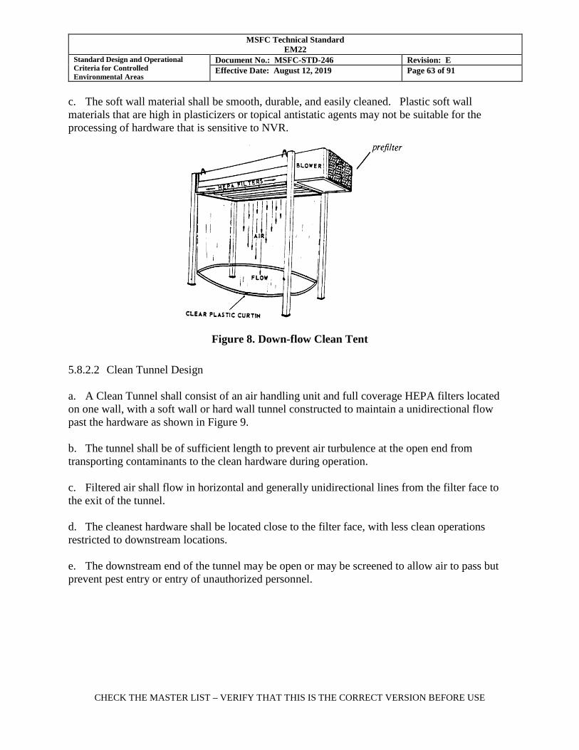
MSFC Technical Standard EM22
Standard Design and Operational Criteria for Controlled Environmental Areas
Document No.: MSFC-STD-246 Revision: E Effective Date: August 12, 2019 Page 63 of 91
CHECK THE MASTER LIST – VERIFY THAT THIS IS THE CORRECT VERSION BEFORE USE
c. The soft wall material shall be smooth, durable, and easily cleaned. Plastic soft wall materials that are high in plasticizers or topical antistatic agents may not be suitable for the processing of hardware that is sensitive to NVR.
Figure 8. Down-flow Clean Tent
5.8.2.2 Clean Tunnel Design a. A Clean Tunnel shall consist of an air handling unit and full coverage HEPA filters located on one wall, with a soft wall or hard wall tunnel constructed to maintain a unidirectional flow past the hardware as shown in Figure 9. b. The tunnel shall be of sufficient length to prevent air turbulence at the open end from transporting contaminants to the clean hardware during operation. c. Filtered air shall flow in horizontal and generally unidirectional lines from the filter face to the exit of the tunnel. d. The cleanest hardware shall be located close to the filter face, with less clean operations restricted to downstream locations. e. The downstream end of the tunnel may be open or may be screened to allow air to pass but prevent pest entry or entry of unauthorized personnel.
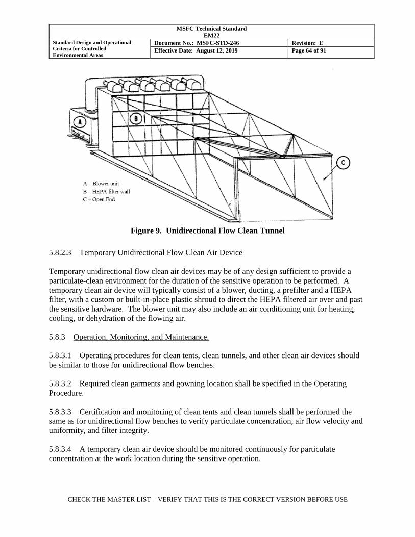
MSFC Technical Standard EM22
Standard Design and Operational Criteria for Controlled Environmental Areas
Document No.: MSFC-STD-246 Revision: E Effective Date: August 12, 2019 Page 64 of 91
CHECK THE MASTER LIST – VERIFY THAT THIS IS THE CORRECT VERSION BEFORE USE
Figure 9. Unidirectional Flow Clean Tunnel
5.8.2.3 Temporary Unidirectional Flow Clean Air Device Temporary unidirectional flow clean air devices may be of any design sufficient to provide a particulate-clean environment for the duration of the sensitive operation to be performed. A temporary clean air device will typically consist of a blower, ducting, a prefilter and a HEPA filter, with a custom or built-in-place plastic shroud to direct the HEPA filtered air over and past the sensitive hardware. The blower unit may also include an air conditioning unit for heating, cooling, or dehydration of the flowing air. 5.8.3 Operation, Monitoring, and Maintenance. 5.8.3.1 Operating procedures for clean tents, clean tunnels, and other clean air devices should be similar to those for unidirectional flow benches. 5.8.3.2 Required clean garments and gowning location shall be specified in the Operating Procedure. 5.8.3.3 Certification and monitoring of clean tents and clean tunnels shall be performed the same as for unidirectional flow benches to verify particulate concentration, air flow velocity and uniformity, and filter integrity. 5.8.3.4 A temporary clean air device should be monitored continuously for particulate concentration at the work location during the sensitive operation.
MSFC Technical Standard EM22
Standard Design and Operational Criteria for Controlled Environmental Areas
Document No.: MSFC-STD-246 Revision: E Effective Date: August 12, 2019 Page 65 of 91
CHECK THE MASTER LIST – VERIFY THAT THIS IS THE CORRECT VERSION BEFORE USE
5.8.3.5 Maintenance operations for unidirectional flow clean air devices are the same as for flow benches. 5.9 Certification and Monitoring Practices. 5.9.1 Data and Record Retention Clean work area (CWA) certification and monitoring data are provided to the CWA custodian, and are permanently stored on the Materials Test, Chemistry and Contamination Control Branch electronic database. 5.9.2 Certification of Controlled Clean Facilities. 5.9.2.1 Initial Certification. Facility certification shall be performed in the operational condition, upon completion of facility construction and equipment installation and prior to exposure of clean flight hardware or other sensitive hardware. Facility inspections and tests should be also performed in the as-built and at rest conditions to detect and repair facility deficiencies earlier in the schedule. Failure to meet initial certification requirements will be communicated to the clean area Custodian who, in coordination with appropriate stake holders and customers, shall decide whether to proceed at risk with planned activities, or to explore options such as embedded clean areas, alternative locations, etc. 5.9.2.2 Recertification Recertification shall be required when: a. The facility fails to meet performance requirements to an extent that facility repairs are required (such as replacement of HEPA filters or HVAC equipment). Temporary deviations from the specified requirements are not cause for recertification. b. Major modifications are made to the facility, e.g., relocation of walls, replacement or redesign of HVAC equipment or ducting, or upgrades to reclassify the facility to a higher cleanliness class. c. An Idle Cleanroom (Section 3.2.25) is being returned to operational status. 5.9.2.3 Tests for Facility Certification a. Tests shall be performed for filter integrity, particulate concentration, temperature, relative humidity, airflow velocity, and pressure, as required, to verify that the facility meets the requirements shown in Table I for the applicable clean facility class, or as tailored in the Operating Procedure.
MSFC Technical Standard EM22
Standard Design and Operational Criteria for Controlled Environmental Areas
Document No.: MSFC-STD-246 Revision: E Effective Date: August 12, 2019 Page 66 of 91
CHECK THE MASTER LIST – VERIFY THAT THIS IS THE CORRECT VERSION BEFORE USE
b. Tests for illumination, total airborne hydrocarbons, particulate fallout rate, NVR deposition rate, and optical deposition may also be required by the Operating Procedure or by the facility construction specification. c. Prior to certification of the clean facility, all installed high purity fluid systems (high purity air, deionized water, etc.) shall be tested for purity and verified to meet the applicable specification or tagged as “out of service” or “not approved for use”. This requirement does not apply to drinking fountains or deluge showers. 5.9.3 Test Methods. The following test methods shall be used when certifying or monitoring a cleanroom, CWA, or clean controlled facility for the specified parameters. 5.9.3.1 Filter Integrity For initial certification of new cleanrooms, flow benches, and clean air devices, and for recertification when the HEPA filters have been removed and reinstalled or replaced, the installed HEPA filters and filter seals shall be inspected to verify the absence of leaks. Inspection of filter systems for leaks is recommended in controlled clean areas and CWAs. The vendor of the HEPA filters may provide this service as a part of the purchase contract. NOTE: Flow benches, clean tents, and other modular clean air devices may be inspected for installed filter integrity at the vendor facility, provided that there is assurance that the filter integrity has not been compromised during shipment to the use location. a. The HEPA filter installation shall be tested to detect leakage by scanning the surface of the HEPA filter media and filter seals with a discrete particle counter during operation of the HVAC system.
b. An aerosol challenge shall be present upstream of the HEPA filter of sufficient concentration to verify that pinhole leaks and poor seals are detected. This upstream aerosol challenge may be natural ambient particulate (supplied by removing the filters upstream of the HEPA filter) if sufficient concentration is present for leak detection. If the concentration of natural ambient challenge is insufficient, an external solid aerosol such as Polystyrene Latex (PSL) microspheres may be injected into the air upstream of the HEPA filters for this test. Reference IEST-RP-CC034, “HEPA and ULPA Filter Leak Tests”, for guidance. The duration of exposure of the HEPA filter to ambient challenge or an injected aerosol should be limited because excessive exposure will shorten the life of the filter.
c. Inspection of the HEPA filter installation for leakage should be performed with the facility in the as-built condition, prior to installation of project equipment.
MSFC Technical Standard EM22
Standard Design and Operational Criteria for Controlled Environmental Areas
Document No.: MSFC-STD-246 Revision: E Effective Date: August 12, 2019 Page 67 of 91
CHECK THE MASTER LIST – VERIFY THAT THIS IS THE CORRECT VERSION BEFORE USE
d. Pinhole leaks in the HEPA filter media may be repaired provided that the repaired surface area is less than 5% of the surface area of the filter media. Filter installation seals may be repaired or replaced. HEPA filters that contain excessive leaks shall be replaced. In clean facilities that are highly sensitive to NVR contamination, the Custodian may prohibit repair of HEPA filter media leaks or may restrict the selection of sealant materials used for leak repair. 5.9.3.2 Particulate Concentration. Sampling and measurement of particulate concentration shall be performed in accordance with Appendix A. 5.9.3.3 Temperature a. Temperature shall be measured using a calibrated temperature sensor with an accuracy of +/- 0.5oC (1oF) in the range of 0 to 50oC (32 to 122oF). NOTE: Temperature/humidity sensors mounted internal to a discrete particle counter have been found to provide inaccurate readings due to heat generation from the adjacent electronics. Externally mounted temperature/humidity sensors are acceptable. b. The temperature may vary from point to point throughout a conventional flow facility, particularly at different elevations. For certification of a non-unidirectional flow facility, a temperature reading shall be taken at each particle sampling location to establish the variability of temperature of the room. Temperature variations are expected to be practically nonexistent in unidirectional flow rooms. c. Once the variability of temperature in the room has been established, the number of test locations may be reduced for monitoring purposes. d. The temperature at a 1 to 2 meter elevation in an area surrounding the work shall be periodically monitored to verify continued compliance with established limits. In high bay facilities where work is located on elevated stands, periodic temperature recording by the Custodian is recommended at these elevated locations. e. Temperature readings within one meter of a heat producing unit are not valid for certification or monitoring purposes. 5.9.3.4 Relative Humidity a. Relative humidity shall be measured using a calibrated humidity sensor with an accuracy of +/- 2% in the range of 10% to 95% relative humidity. b. Sampling locations for relative humidity shall be the same as the sampling locations for temperature for that facility.
MSFC Technical Standard EM22
Standard Design and Operational Criteria for Controlled Environmental Areas
Document No.: MSFC-STD-246 Revision: E Effective Date: August 12, 2019 Page 68 of 91
CHECK THE MASTER LIST – VERIFY THAT THIS IS THE CORRECT VERSION BEFORE USE
5.9.3.5 Airflow Velocity and Uniformity a. Air velocity in unidirectional flow cleanrooms, flow benches, and unidirectional clean air devices shall be measured with an air velocity meter capable of measuring a velocity range of 0-2.5 m/s (0-500 ft/min) or greater and a resolution of 0.01 m/s (2 ft/min) or better. b. The velocity meter should be small and easily handled. An extended probe will aid in the measurement of velocity in elevated locations within cleanrooms. c. Airflow velocity shall be measured in several locations at the same distance from the HEPA filter face (or diffuser face if a plenum distribution system is used) with no obstructions between the filter (diffuser) face and the velocity meter. The recommended distance is 30 to 50 cm (12 to 20 inches). d. For unidirectional cleanroom certification, airflow velocity measurements should be recorded in a grid at approximately every 0.5 m2 (6 ft2) or at the approximate center of each HEPA filter. e. It may be useful to visualize the airflow patterns in a clean facility that is very large, of non-rectangular construction, or that contains large obstructions. Irregular airflow patterns in non-unidirectional facilities and in unidirectional facilities that contain large obstructions may re-circulate airborne contaminants resulting in localized zones of higher contamination. The recommended test method for this is the dispersion-string test described in IEST-RP-CC006, “Testing Cleanrooms”. Visualization of airflow with an aerosol smoke generator is not recommended and may result in excessive contamination of an NVR-sensitive facility. 5.9.3.6 Room Air Change Rate For certification of non-unidirectional flow clean facilities, the room air change rate per hour may be calculated from the average airflow velocity and the room dimensions. Airflow velocity is measured as described in 5.9.2.5 at the locations (HEPA filters or diffusers) where the air enters the room. The air change rate approximately equals (average velocity x room cross-sectional flow area)/room volume. Once established, periodic measurement of air change rate is not required unless the HVAC system is modified or a problem is suspected. 5.9.3.7 Pressure Differential a. Pressure differential measurement shall be measured with an analog or digital manometer with each opening vented in such a manner that the pressure differential is measured between the cleanroom and its outside surroundings, with a range of 0 to 125 Pa (0-0.50 inches of water) and a resolution of 2.5 Pa (0.01 inches of water)
b. The pressure differential reading shall meet the positive pressure requirements shown in Table I for initial certification of the facility.

MSFC Technical Standard EM22
Standard Design and Operational Criteria for Controlled Environmental Areas
Document No.: MSFC-STD-246 Revision: E Effective Date: August 12, 2019 Page 69 of 91
CHECK THE MASTER LIST – VERIFY THAT THIS IS THE CORRECT VERSION BEFORE USE
c. The manometer or pressure gauge may be installed in a wall or may be a portable device. d. Should the facility fail to meet the positive pressure specifications during routine monitoring, an investigation shall be performed by the Custodian, or designee, to locate and correct the problem. A loss of positive pressure may be caused by a door that has been blocked open, plugged air filters, degradation of door seals, a recirculating HVAC system, or damage to the HVAC system (such as air duct penetration or blower degradation). Failure to meet the minimum pressure specification of the room during routine monitoring is not, in itself, cause for decertification. 5.9.3.8 Illumination a. Illumination should be verified during certification of a new facility. Periodic monitoring is not required. b. Illumination shall be measured with a portable photoelectric illumination meter. c. Light sources require an initial seasoning period and a warm-up period for accurate measurement of illumination.
(1) Fluorescent lighting shall be tested after an initial seasoning period of 100 operational hours and 2 hours of warm up.
(2) Incandescent lighting shall be tested after an initial seasoning period of 20 operational hours and a warm up period sufficient to allow the lighting to warm up to full illumination level.
d. Measurement shall be performed at the general work level. 5.9.3.9 Total Airborne Hydrocarbons A facility limit for total airborne hydrocarbons is established by the Custodian and will not be required for most facilities. When such a limit is specified, a portable hydrocarbon analyzer capable of detecting one part per million of methane, calibrated and operated in accordance with the manufacturer’s instructions, may be used for this measurement. 5.9.3.10 Particulate Fallout and NVR Deposition Rates Rates of particle fallout and NVR deposition within a facility may be evaluated by placing fallout plates at selected locations for a defined period of time and then measuring the accumulation of contaminant on the plates during that period. These measurements are not required for certification or monitoring of the facility, but are highly recommended for flight or other critical hardware to detect gross contamination as particles larger than 25 microns are not detectable with particle counters. Witness surfaces may be requested by the Custodian in
MSFC Technical Standard EM22
Standard Design and Operational Criteria for Controlled Environmental Areas
Document No.: MSFC-STD-246 Revision: E Effective Date: August 12, 2019 Page 70 of 91
CHECK THE MASTER LIST – VERIFY THAT THIS IS THE CORRECT VERSION BEFORE USE
consultation with the CCE. Particle fallout may vary considerably, depending on personnel occupancy, level of activity in the room, and the level of operational control of particulate generating sources. NVR deposition may vary based on the presence of hydrocarbon sources in the room and, if the facility does not have hydrocarbon filters, hydrocarbon sources located near the makeup air inlet to the HVAC system. The following test methods are available to characterize these rates: a. Particulate Fallout Measurement Particulate Fallout rate may be analyzed and reported as a quantified particulate level in accordance with IEST-STD-CC1246, “Product Cleanliness Levels and Contamination Control Program” or other particulate standard, or as percent area coverage, deposited during a specified time period (typically per week or per month). ASTM E 2088, “Standard Practice for Selecting, Preparing, Exposing, and Analyzing Witness Surfaces for Measuring Particle Deposition in Cleanrooms and Associated Controlled Environments”, may be used as a guide for selecting measurement methods and protocols. Recommended methods for witness surface particulate counting include optical microscopy and optical imaging. b. NVR Deposition Measurement NVR deposition rate is typically analyzed gravimetrically and reported in mg/0.1m2 (or the mixed unit of mg/ft2) per month. ASTM E 1235, “Standard Test Method for Gravimetric Determination of Nonvolatile Residue (NVR) in Environmentally Controlled Areas for Spacecraft”, may be used as a guide for measurement of NVR deposition rates. c. Optical Witness Sample Measurement Rooms may be rated for optical cleanliness by placing optical witness samples in selected locations, controlling their temperatures to that of nearby critical items, then reading their results per optical acceptance criteria defined in MSFC-SPEC-2223, “Outgassing Test for Materials Associated with Sensitive Optical Surfaces in an Ambient Environment”, or as established by the optic designer. 5.9.4 Routine Monitoring of Clean Facilities. 5.9.4.1 Clean Facilities shall be periodically monitored to verify the continued performance of the facility as specified in Table I or the Operating Procedure. Failure to meet the requirements as specified in Table I or the Operating Procedure will be communicated to the clean area Custodian who, in coordination with appropriate stake holders and customers, shall decide whether to proceed at risk with planned activities, or to explore options such as embedded clean areas, alternative locations, etc.
MSFC Technical Standard EM22
Standard Design and Operational Criteria for Controlled Environmental Areas
Document No.: MSFC-STD-246 Revision: E Effective Date: August 12, 2019 Page 71 of 91
CHECK THE MASTER LIST – VERIFY THAT THIS IS THE CORRECT VERSION BEFORE USE
Work areas designated as Idle Cleanrooms by the Custodian in consultation with the CCE will be checked on an as-needed basis and recertified in preparation to reclassify as a Clean Room per A3.5 at least three (3) weeks before operations recommence in the room. Failure to maintain a routine monitoring schedule as specified in Table I or the Operating Plan shall result in the facility being classified as an Idle Cleanroom, which will necessitate recertification before activities can resume. 5.9.4.2 Periodic monitoring shall be performed using calibrated instruments separate from those used within the facility for continuous monitoring. These measurements should demonstrate correlation; however, periodic monitoring may also detect failure or degradation of the continuous monitoring device. 5.9.4.3 Facility monitoring equipment calibration and service records shall be maintained and made available to inspectors. 5.9.4.4 Facilities located at MSFC (not including MAF) shall be sampled for particulate concentration, temperature, humidity, pressure differential, and air velocity by the M&P Laboratory, Materials Test, Chemistry and Contamination Control Branch. 5.9.4.5 Sampling data recorded by the Materials Test, Chemistry and Contamination Control Branch will be posted at the clean facility on MSFC form 3163, “Materials and Processes Laboratory Chemistry Services”. 5.9.4.6 Facilities located at MAF shall be sampled by the Michoud Facility Operations Contractor and posted at the clean facility on MSFC form 3163 or equivalent. 5.9.4.7 In accordance with MPR 5340.1, the organization sampling the clean facility during routine monitoring shall notify the Custodian when sampling results show that the facility class designation is violated. 5.9.4.8 The Custodian shall respond to specification violations in accordance with MPR 5430.1. 5.9.5 Scheduled or Unscheduled HVAC System Shutdown 5.9.5.1 When a clean facility HVAC system is shut down, whether scheduled or unscheduled, the environmental parameters of Table I, as implemented in the approved Operating Procedure, and the visual cleanliness of facility surfaces shall be re-verified prior to resuming operations. At the custodian’s discretion, visual surface verification may be waived for outages of less than 15 minutes. 5.9.5.2 Contamination sensitive hardware exposed during the shutdown shall be inspected for contamination and corrective measures taken, if required, in accordance with Project and Operating Procedure requirements.
MSFC Technical Standard EM22
Standard Design and Operational Criteria for Controlled Environmental Areas
Document No.: MSFC-STD-246 Revision: E Effective Date: August 12, 2019 Page 72 of 91
CHECK THE MASTER LIST – VERIFY THAT THIS IS THE CORRECT VERSION BEFORE USE
6.0 NOTES 6.1 Contamination Control. This section describes the various types of facility contamination that are regularly monitored at MSFC. These include both airborne contaminants and surface deposits. Airborne contaminants are dependent on a facility's air conditioning and filtration system. However, processing operations within a facility have been shown to significantly increase airborne particle counts and volatile hydrocarbon levels. Deposition of these contaminants on surfaces is of greater concern to the hardware. Although deposits on witness surfaces or flight hardware are related to the facility air conditioning and filtration system, a strong correlation exists between surface deposition and operational activities and controls. It should be noted, however, that even in the cleanest of facilities with minimal activities and strict controls, particle fallout will occur and continue to accumulate on exposed surfaces with time (see Figure 10). For critical optics, fallout over time will obscure light transmission/reflection (surface obscuration), significantly impacting performance. 6.1.1 Types of Contamination. 6.1.1.1 Airborne Particulate Matter:
a. Description Airborne particulate is matter suspended in the ambient atmosphere. These particles are usually very small, i.e., submicron to perhaps 30 μm in size. This particulate may be described as an "aerosol" - a gaseous suspension of fine solid or liquid particles (ref. ASTM E 2217). Aerosols can remain suspended in air currents for prolonged periods but are inclined to settle out over time due to forces such as gravity, surface electrostatic attraction, and aggregation into larger particles.
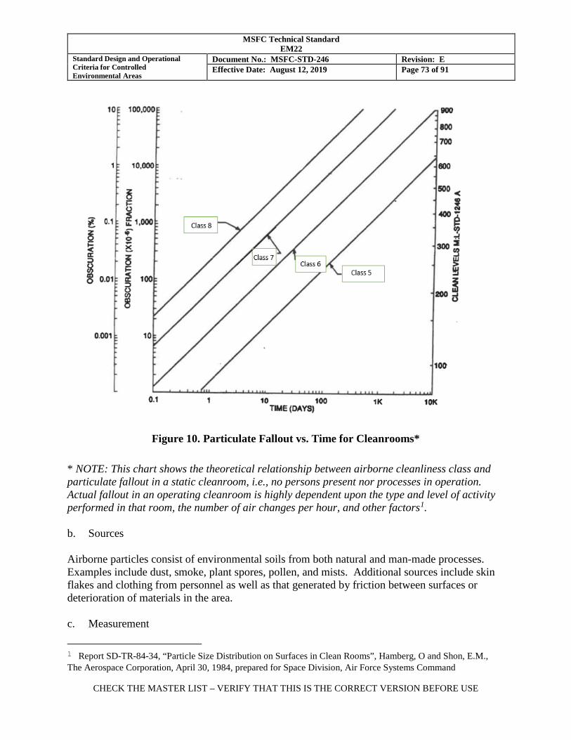
MSFC Technical Standard EM22
Standard Design and Operational Criteria for Controlled Environmental Areas
Document No.: MSFC-STD-246 Revision: E Effective Date: August 12, 2019 Page 73 of 91
CHECK THE MASTER LIST – VERIFY THAT THIS IS THE CORRECT VERSION BEFORE USE
Figure 10. Particulate Fallout vs. Time for Cleanrooms*
* NOTE: This chart shows the theoretical relationship between airborne cleanliness class and particulate fallout in a static cleanroom, i.e., no persons present nor processes in operation. Actual fallout in an operating cleanroom is highly dependent upon the type and level of activity performed in that room, the number of air changes per hour, and other factors1. b. Sources Airborne particles consist of environmental soils from both natural and man-made processes. Examples include dust, smoke, plant spores, pollen, and mists. Additional sources include skin flakes and clothing from personnel as well as that generated by friction between surfaces or deterioration of materials in the area. c. Measurement
1 Report SD-TR-84-34, “Particle Size Distribution on Surfaces in Clean Rooms”, Hamberg, O and Shon, E.M., The Aerospace Corporation, April 30, 1984, prepared for Space Division, Air Force Systems Command
MSFC Technical Standard EM22
Standard Design and Operational Criteria for Controlled Environmental Areas
Document No.: MSFC-STD-246 Revision: E Effective Date: August 12, 2019 Page 74 of 91
CHECK THE MASTER LIST – VERIFY THAT THIS IS THE CORRECT VERSION BEFORE USE
Airborne particulates in the 0.01 μm to 25 μm range are monitored with a discrete particle counting device to assure that the facility air filtration system is fully functional and that hardware operations, housekeeping, and personnel procedures are effectively limiting the generation of airborne particulate. Particles larger than 25 μm fall out and are not accurately measured by automated airborne particle counters. 6.1.1.2 Surface Particulate Matter a. Description Surface particulate is matter deposited on the surface of an item or a part. This is typically a combination of particle sizes resulting from fine particle settling and large particle fallout. b. Sources Large particles are generated by personnel, particle producing operations and materials, and environmental soils introduced into a facility. Typical sources of large particles include paper products, clothing fibers, hair, dust, chipping or flaking of finishes, and friction. Particles may be deposited by fallout from overhead operations; may be generated at the surface by handling or deterioration of nearby materials; or may be transferred by contact, air currents, or ejection from adjacent particle-generating operations. c. Measurement Particle deposition may be analyzed and reported as a quantified particulate level in accordance with IEST-STD-CC1246 or other particulate standard, or as percent area coverage. There are several methods are available to quantify particulate matter on surfaces.
(1) Direct sampling by flushing the surface with a compatible solvent: The solvent is then filtered and the particles on the filter are sized and counted. The results are reported in particles per square foot. Reference ASTM F 303, “Standard Practices for Sampling for Particles in Aerospace Fluids and Components”, and ASTM F 312, “Standard Test Methods for Microscopical Sizing and Counting Particles from Aerospace Fluids on Membrane Filters”.
(2) Indirect measurement of adjacent witness surfaces: Particulate filters, stainless steel
panels, silicon wafers, or other witness surfaces are pre-cleaned, placed in an area for a specified period of time and then analyzed to quantify particulate accumulation over time. Particles on filters are counted microscopically in accordance with ASTM F 312. Particles on stainless steel panels are solvent flushed and then quantified as described in method 1. Particles on silicon wafers or other direct witness surfaces may be quantified by optical image analysis or other automated methods. Reference ASTM E 2088.
MSFC Technical Standard EM22
Standard Design and Operational Criteria for Controlled Environmental Areas
Document No.: MSFC-STD-246 Revision: E Effective Date: August 12, 2019 Page 75 of 91
CHECK THE MASTER LIST – VERIFY THAT THIS IS THE CORRECT VERSION BEFORE USE
(3) Tape lift: When a surface is not accessible or suitable for solvent flushing, a tape lift may be used to directly sample the surface. Reference ASTM E 1216, “Standard Practice for Sampling for Particulate Contamination by Tape Lift”.
(4) Visual inspection: For characterization of large surfaces where analysis of particles
smaller than 100 μm is not required, the surfaces may be visually inspected under defined conditions of inspection distance and illumination by white or ultraviolet light. Standard inspection conditions and acceptance criteria for visual cleanliness are provided in IEST-STD-CC1246 Product Cleanliness Levels and Contamination Control Program. .
(5) Direct real-time measurement using glancing light technology: Optical devices that
perform direct surface particle measurement using glancing light technology have shown promise in situations where the background surface is compatible with the technique.
6.1.1.3 Airborne Molecular Contaminants a. Description Airborne molecular contaminants are those gaseous chemicals dispersed in ambient air. This includes volatile hydrocarbons, silicones, and other chemicals. b. Sources Naturally occurring and man-made sources in the air are generated by decomposition, combustion, volatile solvents, paints, sealant curing by-products, outgassing, and internal combustion engines. Airborne molecular contaminants are not removed by High Efficiency Particulate Air (HEPA) filters. Molecular adsorbers (gas-phase adsorber cells) may be included in the filtration system when required to remove these contaminants. These typically consist of activated carbon or zeolite, but other materials are also used. Reference ASTM E 2217 and IEST-RP-CC008, High-Efficiency Gas-Phase Adsorber Cells. c. Measurement A sample of facility atmosphere is drawn into an on-site analyzer or an evacuated sample container for transport and analysis in a laboratory. Volatile hydrocarbons are analyzed by a total volatile hydrocarbon analyzer and reported in parts per million (ppm) volume/volume (v/v), methane equivalent. The potential for materials to outgas molecular contaminants in the ambient environment may be evaluated by MSFC-SPEC-2223. 6.1.1.4 Nonvolatile Residue (NVR) a. Description
MSFC Technical Standard EM22
Standard Design and Operational Criteria for Controlled Environmental Areas
Document No.: MSFC-STD-246 Revision: E Effective Date: August 12, 2019 Page 76 of 91
CHECK THE MASTER LIST – VERIFY THAT THIS IS THE CORRECT VERSION BEFORE USE
Soluble or suspended material and insoluble particulate matter remaining after controlled evaporation of a filtered volatile liquid. It typically consists of hydrocarbons, silicones, and other higher molecular weight species deposited through condensation, direct contact transmission, or as a residue remaining after evaporation of a liquid. The amount of NVR collected from a surface is used as the basis for the quantification of soluble contaminants, such as hydrocarbon films, on that surface. NVR is usually reported in milligrams per unit area (for surfaces) or milligrams per unit volume (in fluids). b. Sources Lubricating oils and greases, plasticizers from non-metallic materials, fumes from internal combustion engines, skin oils (fingerprints), oil fumes from hydraulics, vacuum pumps and motors, mold release agents, and deposition of airborne molecular contaminants. For highly sensitive optical hardware, personal grooming items such as colognes and hair treatments may be a source of unacceptable NVR. c. Measurement NVR may be sampled from surfaces per ASTM F 303 or MSFC-PROC-1832, “The Sampling and Analysis of Nonvolatile Residue Content on Critical Surfaces “, and analyzed per ASTM F 331, “Standard Test Method for Nonvolatile Residue of Solvent Extract from Aerospace Components (Using Flash Evaporator)”. NVR deposition may be characterized by the use of witness surfaces, and is typically reported in milligrams per unit area per month. Reference ASTM E 1235.
6.1.1.5 Microbial Contamination a. Description Microbial contamination includes microscopic biological materials such as bacteria (typically 0.2 to 50 μm in diameter), fungal spores (0.5 to 60 μm) and viruses (<0.1 μm). This category includes both human pathogens and other viable organisms that are not human pathogens. b. Source Microbial materials are introduced by airflow from external sources, personnel, and environmental soils carried into the facility on personnel and equipment. Microbial materials may also be introduced by pests such as insects, rodents, and reptiles that enter the facility. c. Measurement Microbial monitoring of facilities will not be performed unless dictated by facility operations or program manager. Decayed or living matter deposited on surfaces within the facility will be classified as particulate matter and/or NVR, unless otherwise directed, and monitored by the
MSFC Technical Standard EM22
Standard Design and Operational Criteria for Controlled Environmental Areas
Document No.: MSFC-STD-246 Revision: E Effective Date: August 12, 2019 Page 77 of 91
CHECK THE MASTER LIST – VERIFY THAT THIS IS THE CORRECT VERSION BEFORE USE
appropriate particulate and NVR tests. Methods for control and measurement of microbial contaminants in clean environments are found in IEST-RP-CC023, “Microorganisms in Cleanrooms”. 6.2 Establishment of Hardware Cleanliness Requirements. 6.2.1 Spacecraft. Guidance for establishing system and subsystem contamination limits and budget allocations for spacecraft may be found in ASTM E 1548, “Standard Practice for Preparation of Aerospace Contamination Control Plans”, and ISO 15388, “Space Systems – Contamination and Cleanliness Control”. 6.2.2 Fluid Systems. Cleanliness requirements for the interior surfaces of fluid systems are derived based on many factors, such as:
• The smallest orifice diameter in the system: The three ball equation provides a conservative maximum particle size to prevent three particles that enter an orifice simultaneously from plugging the orifice. The three ball equation yields a maximum particle size of approximately 7/16 of the orifice diameter.
• Sensitivity of the system to wear resulting from small particles entrained in the fluid
• The potential for ignition of the fluid by particulate or molecular contamination
• The tendency for contaminants to feed microbial growth in high purity water
6.2.3 Electrical, Electronic, and Electromechanical Components. 6.2.3.1 The following NASA documents establish minimum cleanliness requirements and associated environmental controls for electrical, electronic, and electromechanical (EEE) components:
• NASA-STD-8739.1, “Workmanship Standard for Polymeric Application on Electronic Assemblies”
• NASA-STD-8739.5, “Fiber Optic Terminations, Cable Assemblies, and Installation”
6.2.3.2 More stringent requirements may be required for EEE components to prevent cross-contamination of spacecraft optics, thermal control surfaces, or fluid systems.
MSFC Technical Standard EM22
Standard Design and Operational Criteria for Controlled Environmental Areas
Document No.: MSFC-STD-246 Revision: E Effective Date: August 12, 2019 Page 78 of 91
CHECK THE MASTER LIST – VERIFY THAT THIS IS THE CORRECT VERSION BEFORE USE
6.2.4 Mechanisms. 6.2.4.1 Contamination control of spacecraft mechanisms is addressed in NASA-STD-5017, “Design and Development Requirements for Mechanisms”. 6.2.4.2 Testing may be required to determine detrimental contamination levels to prevent binding, jamming, or seizing of mechanisms.
MSFC Technical Standard EM22
Standard Design and Operational Criteria for Controlled Environmental Areas
Document No.: MSFC-STD-246 Revision: E Effective Date: August 12, 2019 Page 79 of 91
CHECK THE MASTER LIST – VERIFY THAT THIS IS THE CORRECT VERSION BEFORE USE
APPENDIX A. Particulate Sampling In Cleanrooms And Other Controlled Clean Areas A1. SCOPE This appendix specifies sampling plans and test methods for certification and periodic monitoring of particulate concentration in cleanrooms and other controlled clean areas at MSFC facilities. The sampling plans are intended for clean facilities with contamination levels and operations typical of cleanrooms and dust-controlled areas designed for aerospace work. A2. APPLICABLE DOCUMENTS ASTM F 25 Standard Test Method for Sizing and Counting Airborne Particulate
Contamination in Cleanrooms and Other Dust-Controlled Areas ASTM F 50 Standard Practice for Continuous Sizing and Counting of Airborne
Particles in Dust-Controlled Areas and Clean Rooms Using Instruments Capable of Detecting Single Sub-Micrometre and Larger Particles
A3. GENERAL PROCEDURE Sampling for particulate in MSFC clean facilities is typically performed with a calibrated portable automatic discrete particle counter. Multiple locations are sampled, with the number and placement of sampling locations determined by the floor area and configuration of the facility. Additional locations may be identified by the Custodian for sampling and must be coordinated with the Materials Test, Chemistry and Contamination Control Branch to be added to the sampling plan. Additional sampling locations may be required for initial certification of the room. NOTE: Discrete Particle Counters purchased in the United States are generally pre-set and calibrated to count particles of the specified micron size and larger per cubic foot of air sampled, with sampling rates specified in cubic feet per minute (cfm). Therefore the units specified in this appendix, except for particle size, are expressed in English units. The user must convert the measured airborne particle concentration into the corresponding ISO Class of clean facility as shown in Table I. A3.1 Sampling Equipment. Sampling for particulate shall be performed using a portable automatic discrete particle counter in accordance with ASTM F 50, “Standard Practice for Continuous Sizing and Counting of Airborne Particles in Dust-Controlled Areas and Clean Rooms Using Instruments Capable of Detecting Single Sub-Micrometre and Larger Particles”. A3.1.1 Selection of Particle Counter.
MSFC Technical Standard EM22
Standard Design and Operational Criteria for Controlled Environmental Areas
Document No.: MSFC-STD-246 Revision: E Effective Date: August 12, 2019 Page 80 of 91
CHECK THE MASTER LIST – VERIFY THAT THIS IS THE CORRECT VERSION BEFORE USE
Automatic particle counters come in various ranges and levels of sensitivity. Particle counters with the highest sensitivity may not be suitable for the range of clean facilities covered in this document. In Class 8 or 8.5 facilities, a particle counter not designed for operation in this range will become saturated, resulting in inaccurate counts. The recommended particle counter will be designed to count particles of 0.3 μm and up and to a concentration limit of 1,000,000/ft3 or more. Particle counters with a lower concentration limit may require a diluter to obtain accurate readings. The particle counter shall report particle counts at 0.5 μm and up and 5.0 μm and up, as a minimum. A3.1.2 Calibration of Particle Counter. The particle counter shall be calibrated in accordance with the manufacturer’s instructions based on established industry practices such as IEST-RP-CC014, “Calibration and Characterization of Optical Particle Counters”, that use calibration standards traceable to the National Institute of Standards and Technology (NIST). A3.1.3 Sample Volume. Automatic particle counters typically sample and count at a sampling rate of either 0.1 cfm or 1.0 cfm, although other sample volumes are available. When automatically sampling an air volume other than 1.0 ft3 the resulting particle count shall be normalized to particles/ft3. A3.1.4 Manual Airborne Particle Counting. In some circumstances, the manual test method described in ASTM F 25, “Standard Test Method for Sizing and Counting Airborne Particulate Contamination in Cleanrooms and Other Dust-Controlled Areas”, may be used. This test method is based on the microscopic examination of particles impinged upon a membrane filter with the aid of a vacuum. This test method may be used only for counting of particulate larger than 5 μm in diameter; therefore, it is not acceptable for certification or monitoring of clean facilities Class 8 and cleaner. This test method may be useful to capture airborne particles for qualitative identification. NOTE: The ASTM F 25 test method is slower and more labor intensive than measurement of airborne particle concentration by automatic discrete particle counter and is not valid for particle counting below 5 μm. For these reasons, the ASTM F 50 test method is preferred. ASTM F 25 may be used when an automatic particle counter is unavailable, when qualitative identification of airborne particles is desired, or as a rough correlation check of particles greater than 5 μm when calibrating automatic particle counters. A3.2 Time of Sampling. A3.2.1 Sampling for facility certification and periodic monitoring shall be performed with the facility in the operational condition. In the operational condition, the facility will be fully
MSFC Technical Standard EM22
Standard Design and Operational Criteria for Controlled Environmental Areas
Document No.: MSFC-STD-246 Revision: E Effective Date: August 12, 2019 Page 81 of 91
CHECK THE MASTER LIST – VERIFY THAT THIS IS THE CORRECT VERSION BEFORE USE
functioning, clean, and with production equipment and personnel present and performing their normal work functions (or a semblance thereof). A3.2.2 Sampling should also be performed in the “as-built” condition after initial construction or major modification to confirm the integrity and maximum capability of the facility. Scanning of the HEPA filter face and seals should be performed at this step to detect leaks and verify the integrity of the filter installation. Sampling in the as-built condition is performed after initial facility cleaning but prior to the installation of production equipment and with no personnel present (except the person operating the particle counter). With the facility in this condition, any HEPA filtered facility may meet Class 5 particulate levels. A3.2.3 Sampling may be performed in the at-rest condition to confirm the integrity of the facility after installation of production equipment but without personnel present (except the person operating the particle counter). With the facility in this condition, a HEPA filtered facility may approach or meet Class 5 particulate levels. A3.3 Sampling Plan. A3.3.1 Unless otherwise specified in the Operating Procedure, flow benches shall be measured at a minimum of two locations, approximately 50 cm (20 inches) from the filter face. This represents a typical distance from filter face where operations are performed. A3.3.2 For clean facilities other than flow benches, a sampling plan shall be selected for the facility. When not otherwise specified in the Operating Procedure, the standard sampling plan will be as follows: a. Samples shall be taken at locations as illustrated on the sampling plan in Figure 11.
(1) Sample at locations A and B for areas less than 150 ft2.
(2) Sample at locations 1, 2, 3, 4 and 5 for areas to 1,000 ft2.
(3) Increase sampling by 4 locations per 1,000 ft2.
NOTE: This number of samples has historically been found to provide adequate characterization of cleanrooms at MSFC. ISO 14644-1 requires 1.5 to 2 times this number of sampling locations. If a user requires certification of a cleanroom to the full sampling requirements of ISO-14644-1, additional sampling locations will be required.
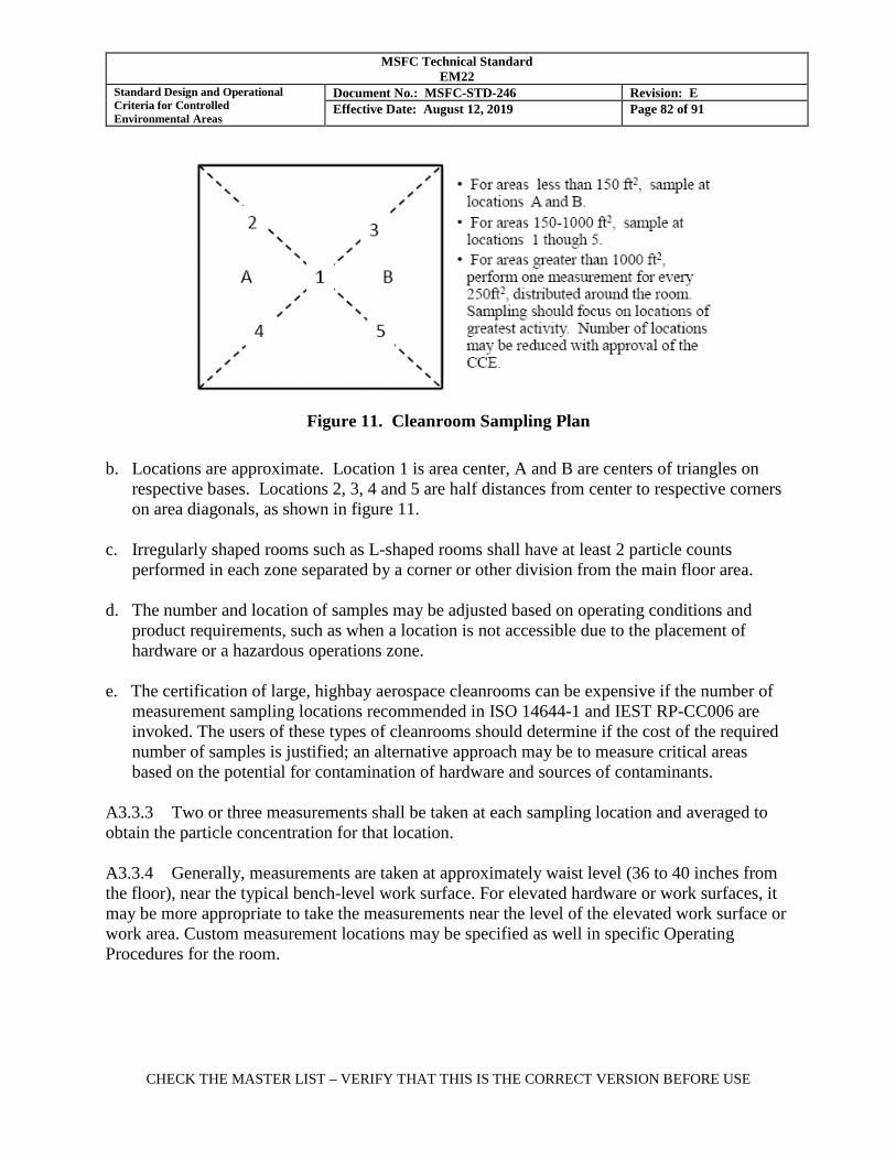
MSFC Technical Standard EM22
Standard Design and Operational Criteria for Controlled Environmental Areas
Document No.: MSFC-STD-246 Revision: E Effective Date: August 12, 2019 Page 82 of 91
CHECK THE MASTER LIST – VERIFY THAT THIS IS THE CORRECT VERSION BEFORE USE
Figure 11. Cleanroom Sampling Plan
b. Locations are approximate. Location 1 is area center, A and B are centers of triangles on
respective bases. Locations 2, 3, 4 and 5 are half distances from center to respective corners on area diagonals, as shown in figure 11.
c. Irregularly shaped rooms such as L-shaped rooms shall have at least 2 particle counts
performed in each zone separated by a corner or other division from the main floor area. d. The number and location of samples may be adjusted based on operating conditions and
product requirements, such as when a location is not accessible due to the placement of hardware or a hazardous operations zone.
e. The certification of large, highbay aerospace cleanrooms can be expensive if the number of
measurement sampling locations recommended in ISO 14644-1 and IEST RP-CC006 are invoked. The users of these types of cleanrooms should determine if the cost of the required number of samples is justified; an alternative approach may be to measure critical areas based on the potential for contamination of hardware and sources of contaminants.
A3.3.3 Two or three measurements shall be taken at each sampling location and averaged to obtain the particle concentration for that location. A3.3.4 Generally, measurements are taken at approximately waist level (36 to 40 inches from the floor), near the typical bench-level work surface. For elevated hardware or work surfaces, it may be more appropriate to take the measurements near the level of the elevated work surface or work area. Custom measurement locations may be specified as well in specific Operating Procedures for the room.
MSFC Technical Standard EM22
Standard Design and Operational Criteria for Controlled Environmental Areas
Document No.: MSFC-STD-246 Revision: E Effective Date: August 12, 2019 Page 83 of 91
CHECK THE MASTER LIST – VERIFY THAT THIS IS THE CORRECT VERSION BEFORE USE
A3.4 Continuous Monitoring. Placement of a continuous particle counter with automatic recording is recommended in critical work locations. Past experience has shown that these work positions should be checked daily, or more often, and during periods of most activity. Placement of a continuous particle counter with computer recording is recommended in critical work locations. This monitoring is the responsibility of the Custodian and the Project responsible for the hardware operations. Continuous monitoring is not a part of the periodic sampling of the facility performed by Materials Test, Chemistry and Contamination Control Branch. A3.5 Facility Certification. A3.5.1 For facility certification, three or more 0.1 ft3 minimum samples shall be taken, averaged, and normalized to 1.0 ft3 for each sampling location. A3.5.2 The average at each test location shall meet the particulate limits for the facility. A3.5.3 For cleanrooms smaller than 2500 ft2 (where fewer than 10 test locations are required) that are used for processing flight hardware or performing critical operations (as determined by the project), the statistical 95% upper confidence limit based on the student’s t distribution shall be calculated from the standard deviation of these location averages. This upper confidence limit shall be lower than the particle count limit for the facility. Reference ISO 14644-1 for sample calculations for determining this upper confidence limit.
MSFC Technical Standard EM22
Standard Design and Operational Criteria for Controlled Environmental Areas
Document No.: MSFC-STD-246 Revision: E Effective Date: August 12, 2019 Page 84 of 91
CHECK THE MASTER LIST – VERIFY THAT THIS IS THE CORRECT VERSION BEFORE USE
APPENDIX B. Monitoring Of Cleanroom Garments
B1. SCOPE This appendix contains inspection, test, and acceptance criteria for the particulate cleanliness and physical condition of cleanroom garments. These criteria are used to determine initial cleanliness of garments that have been constructed, cleaned, and packaged for cleanroom use and to monitor the cleanliness and condition of garments after laundering. B1.1 Application. The requirements of this appendix apply to reusable and disposable cleanroom garments when purchased for cleanroom use. The requirements of this appendix may be applied to garments purchased for use in other types of clean facilities when specified in the Operating Procedure or garment purchase order, or garment laundering contract. B1.2 Limitations. Cleanroom garments may require testing, monitoring, and acceptance limits for static dissipation and extractable matter. Test methods and acceptance criteria for these properties are not a part of this appendix. B2. APPLICABLE DOCUMENTS ASTM E 1216 Standard Practice for Sampling for Particulate Contamination by Tape Lift ASTM F 51 Standard Test Method for Sizing and Counting Particulate Contaminant In
and on Clean Room Garments B3. REQUIREMENTS B3.1 Visual Inspection. B3.1.1 Garments shall be visually inspected for evidence of defects of construction, degradation, damage or visible contamination prior to sampling for particulate. B3.1.2 Acceptance criteria for visual condition shall be in accordance with section B4.1. B3.2 Particulate Testing. B3.2.1 Garments shall be sampled and tested for particulate in accordance with ASTM F 51, “Standard Test Method for Sizing and Counting Particulate Contaminant In and on Clean Room Garments”.
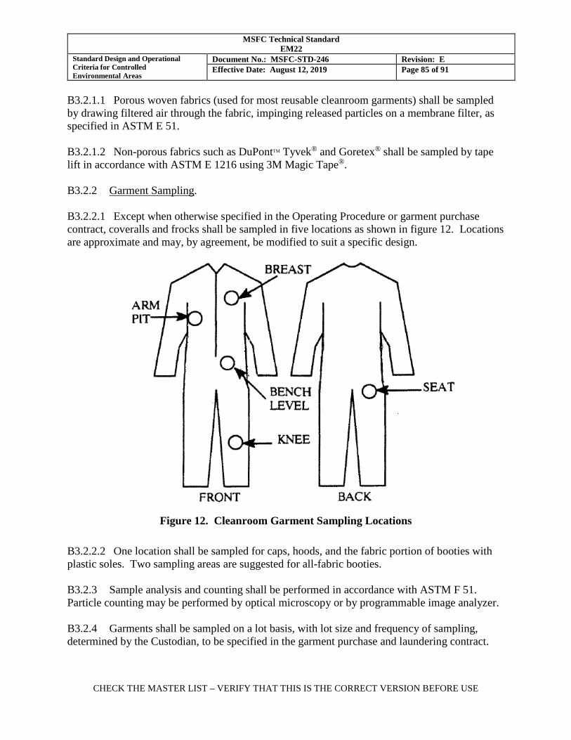
MSFC Technical Standard EM22
Standard Design and Operational Criteria for Controlled Environmental Areas
Document No.: MSFC-STD-246 Revision: E Effective Date: August 12, 2019 Page 85 of 91
CHECK THE MASTER LIST – VERIFY THAT THIS IS THE CORRECT VERSION BEFORE USE
B3.2.1.1 Porous woven fabrics (used for most reusable cleanroom garments) shall be sampled by drawing filtered air through the fabric, impinging released particles on a membrane filter, as specified in ASTM E 51. B3.2.1.2 Non-porous fabrics such as DuPontTM Tyvek® and Goretex® shall be sampled by tape lift in accordance with ASTM E 1216 using 3M Magic Tape®. B3.2.2 Garment Sampling. B3.2.2.1 Except when otherwise specified in the Operating Procedure or garment purchase contract, coveralls and frocks shall be sampled in five locations as shown in figure 12. Locations are approximate and may, by agreement, be modified to suit a specific design.
Figure 12. Cleanroom Garment Sampling Locations
B3.2.2.2 One location shall be sampled for caps, hoods, and the fabric portion of booties with plastic soles. Two sampling areas are suggested for all-fabric booties. B3.2.3 Sample analysis and counting shall be performed in accordance with ASTM F 51. Particle counting may be performed by optical microscopy or by programmable image analyzer. B3.2.4 Garments shall be sampled on a lot basis, with lot size and frequency of sampling, determined by the Custodian, to be specified in the garment purchase and laundering contract.
MSFC Technical Standard EM22
Standard Design and Operational Criteria for Controlled Environmental Areas
Document No.: MSFC-STD-246 Revision: E Effective Date: August 12, 2019 Page 86 of 91
CHECK THE MASTER LIST – VERIFY THAT THIS IS THE CORRECT VERSION BEFORE USE
B3.3 Odor. Cleanroom garments that are worn and laundered repeatedly may develop an objectionable odor over time. A smell test is not required; however, if a strong objectionable odor is detected during visual inspection, the garment shall be rejected and returned for re-laundering. A garment that is routinely cleaned by aqueous method may require occasional dry cleaning to remove objectionable odor. B4. ACCEPTANCE CRITERIA B4.1 Visual Condition. B4.1.1 Obviously broken fibers or lint-bearing seams on the outer surfaces of garments shall be cause for rejection and replacement. B4.1.2 Missing snaps, open seams, holes, broken zippers, or other defects in reusable garments shall be cause for rejection. These garments may be repaired and re-laundered provided that full function of the garment is restored. B4.1.3 Missing snaps, open seams, holes, broken zippers, and other defects in disposable garments shall be cause for rejection and replacement. B4.1.4 Stains, oil spots, or discoloration shall be cause for rejection. Reusable garments may be re-laundered or dry cleaned to remove the stain or replaced when the stain is resistant to removal. A change in gloss of the fabric is to be expected after multiple launderings and is not, by itself, cause for rejection. B4.2 Particulate Limit. Except when otherwise specified in the Operating Procedure or garment purchase contract, a count of detachable particles 5 μm or larger greater than 2150 per 0.1 m2 (2000/ft2) of fabric shall be cause for rejection. B4.3 Disposition of Rejected Garments. B4.3.1 Should the garment particle count exceed the allowable limit, tests shall be made to determine whether the garment is at fault or has been laundered improperly. Close visual inspection, microscopy and/or microchemical methods may be employed to determine whether the garment itself is deteriorating. B4.3.2 Should the garment itself be faulty and is shedding, it shall be discarded or marked and repurposed for non-clean facility use. DuPontTM Tyvek® disposable garments may be collected for recycling2. 2 Recyclers accept used Tyvek garments to reprocess for other garment applications. Tyvek fabric, a flashspun high-
MSFC Technical Standard EM22
Standard Design and Operational Criteria for Controlled Environmental Areas
Document No.: MSFC-STD-246 Revision: E Effective Date: August 12, 2019 Page 87 of 91
CHECK THE MASTER LIST – VERIFY THAT THIS IS THE CORRECT VERSION BEFORE USE
B4.3.3 If the garment has been improperly laundered, all garments from the same wash lot shall be rejected and returned to the laundry for re-cleaning.
density polyethylene, is also recycled by DuPont into other products.
MSFC Technical Standard EM22
Standard Design and Operational Criteria for Controlled Environmental Areas
Document No.: MSFC-STD-246 Revision: E Effective Date: August 12, 2019 Page 88 of 91
CHECK THE MASTER LIST – VERIFY THAT THIS IS THE CORRECT VERSION BEFORE USE
APPENDIX C. Flow Bench General Operating Procedures
NOTE: Flow bench Custodian’s name and contact information shall be conspicuously posted on or near flow bench.
1. Verify bench certification card is current and bench meets cleanliness requirements. 2. Verify airflow and lighting are fully operating. The bench shall be on at least 10 minutes
before operations commence. Ideally, bench should run 24 hours/day. 3. Remove all unnecessary items from bench top. 4. Take all reasonable steps to adequately clean items to be used in bench before placing them
in the clean environment. 5. Never use hazardous solvents while working in flow bench. Use a fume hood for harmful
vapors. 6. Always wear appropriate protective gear (gloves, smock, cap, etc.) when working inside
clean environment. 7. Always work downstream of items in clean air flow and minimize hand movement over
items. Avoid placement of items between the clean product and the filtered air source. 8. Never lean over items in clean area. 9. If necessary for operations, use only high purity, filtered gases. 10. Replace gloves if they are removed from clean environment or come in contact with
exposed skin. 11. Never place paper or paper products in clean bench environment. 12. Use caution when selecting and using materials within flow bench. Avoid using any
materials that may be a potential source of contamination. 13. Move slowly and keep movement to a minimum. 14. Periodically check and replace, as necessary, air system pre-filters. Turn blower motor off
before replacement of pre-filters.
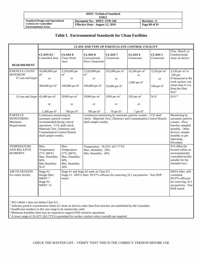
MSFC Technical Standard EM22
Standard Design and Operational Criteria for Controlled Environmental Areas
Document No.: MSFC-STD-246 Revision: E Effective Date: August 12, 2019 Page 89 of 91
CHECK THE MASTER LIST – VERIFY THAT THIS IS THE CORRECT VERSION BEFORE USE
Table I. Environmental Standards for Clean Facilities
REQUIREMENT
CLASS AND TYPE OF PARTICULATE CONTROL FACILITY CLASS 8.5 1 Controlled Area
CLASS 8 Clean Work Area
CLASS 8 Conventional Flow Cleanroom
CLASS 7 Cleanroom
CLASS 6 Cleanroom
CLASS 5 Cleanroom
Flow Bench, or Unidirectional clean air device
PARTICLE COUNT MAXIMUM
0.5 μm and larger
10,600,000 per m3
or
300,000 per ft3
3,520,000 per m3
or
100,000 per ft3
3,520,000 per m3
or
100,000 per ft3
352,000 per m3
or
10,000 per ft3
35,200 per m3
or
1,000 per ft3
3,520 per m3
or
100 per ft3
3,520 per m3 or 100 per ft3measured at the work surface/ not closer than 0.5 m from the filter face2
5.0 μm and larger 42,400 per m3
or
1,200 per ft3
29300 per m3
or
700 per ft3
29300 per m3
or
700 per ft3
2930 per m3
or
70 per ft3
293 per m3
or
7 per ft3
N/A3 N/A2,3
PARTICLE MONITORING Minimum Requirements
Continuous monitoring by automatic particle counter recommended during critical operations. CCE shall check. Materials Test, Chemistry and Contamination Control Branch shall sample weekly.
Continuous monitoring by automatic particle counter. CCE shall check. Materials Test, Chemistry and Contamination Control Branch shall sample weekly.
Monitoring by automatic particle counter. Flow benches sampled monthly. Other devices: sample monthly or per Operating Procedure
TEMPERATURE AND RELATIVE HUMIDITY
Max. Temperature: 27oC (80°F) Max. Humidity: 60% Min Humidity: N/A4
Max. Temperature: 27oC (80°F) Max. Humidity: 60% Min. Humidity: 30%
Temperature: 19-25oC (67-77°F)5 Max. Humidity: 50% Min. Humidity: 30%
N/A (Must be located within an environmentally controlled facility suitable for the intended use.)
AIR FILTRATION For entire facility
Stage #1: Rough filter, MERV 7 Stage #2: MERV 13
Stage #1 and Stage #2 same as Class 8.5. Stage #3: HEPA filter, 99.97% efficient for removing ≥0.3 μm particles. Non DOP tested
HEPA filter, self-contained, 99.97% efficient for removing ≥0.3 μm particles. Non DOP tested.
1 ISO-14644-1 does not define Class 8.5. . 2 Airborne particle concentration limits for clean air devices other than flow benches are established by the Custodian. 3 Insufficient numbers in this size range to be statistically valid. 4 Minimum humidity limit may be required to support ESD sensitive operations. 5 A lower range of 16-22oC (62-72°F) is permitted for worker comfort when coveralls are required.
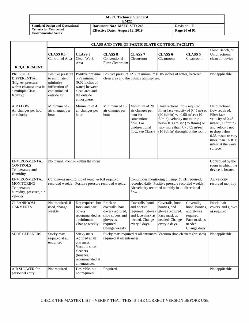
MSFC Technical Standard EM22
Standard Design and Operational Criteria for Controlled Environmental Areas
Document No.: MSFC-STD-246 Revision: E Effective Date: August 12, 2019 Page 90 of 91
CHECK THE MASTER LIST – VERIFY THAT THIS IS THE CORRECT VERSION BEFORE USE
REQUIREMENT
CLASS AND TYPE OF PARTICULATE CONTROL FACILITY CLASS 8.5 1 Controlled Area
CLASS 8 Clean Work Area
CLASS 8 Conventional Flow Cleanroom
CLASS 7 Cleanroom
CLASS 6 Cleanroom
CLASS 5 Cleanroom
Flow Bench, or Unidirectional clean air device
PRESSURE DIFFERENTIAL (Highest pressure within cleanest area in a multiple Class facility.)
Positive pressure to eliminate or minimize infiltration of contaminated outside air.
Positive pressure 5 Pa minimum (0.02 inches of water) between clean area and the outside atmosphere.
Positive pressure 12.5 Pa minimum (0.05 inches of water) between clean area and the outside atmosphere.
Not applicable
AIR FLOW Air changes per hour or velocity
Minimum of 2 air changes per hour
Minimum of 4 air changes per hour
Minimum of 15 air changes per hour
Minimum of 20 air changes per hour for conventional flow. For unidirectional flow, see Class 6
Unidirectional flow required. Filter face velocity of 0.45 m/sec (90 ft/min) +/- 0.05 m/sec (10 ft/min); velocity not to drop below 0.38 m/sec (75 ft/min) or vary more than +/- 0.05 m/sec (10 ft/min) throughout the room.
Unidirectional flow required. Filter face velocity of 0.45 m/sec (90 ft/min) and velocity not to drop below 0.38 m/sec or vary more than +/- 0.05 m/sec at the work surface.
ENVIRONMENTAL CONTROLS Temperature and Humidity
No manual control within the room Controlled by the room in which the device is located.
ENVIRONMENTAL MONITORING Temperature, humidity, pressure, air velocity
Continuous monitoring of temp. & RH required; recorded weekly. Positive pressure recorded weekly.
Continuous monitoring of temp. & RH required; recorded daily. Positive pressure recorded weekly. Air velocity recorded monthly in unidirectional flow.
Air velocity recorded monthly
CLEANROOM GARMENTS
Not required. If used, change weekly.
Not required, but frock and hair covers recommended as a minimum. Change weekly.
Frock or coveralls, hair covers required; shoe covers and gloves as required. Change weekly.
Coveralls, hood, and booties required. Gloves and face mask as needed. Change every 3 days.
Coveralls, hood, booties, and gloves required. Face mask as needed. Change every 2 days.
Coveralls, hood, booties, and gloves required. Face mask as needed. Change daily.
Frock, hair covers, and gloves as required.
SHOE CLEANERS Sticky mats required at all entrances
Sticky mats required at all entrances. Vacuum shoe cleaners (brushes) recommended at all entrances.
Sticky mats required at all entrances. Vacuum shoe cleaners (brushes) required at all entrances.
Not applicable
AIR SHOWER for personnel entry
Not required Desirable, but not required
Required Not applicable

MSFC Technical Standard EM22
Standard Design and Operational Criteria for Controlled Environmental Areas
Document No.: MSFC-STD-246 Revision: E Effective Date: August 12, 2019 Page 91 of 91
CHECK THE MASTER LIST – VERIFY THAT THIS IS THE CORRECT VERSION BEFORE USE
REQUIREMENT
CLASS AND TYPE OF PARTICULATE CONTROL FACILITY CLASS 8.5 1 Controlled Area
CLASS 8 Clean Work Area
CLASS 8 Conventional Flow Cleanroom
CLASS 7 Cleanroom
CLASS 6 Cleanroom
CLASS 5 Cleanroom
Flow Bench, or Unidirectional clean air device
AIR LOCKS Desirable, but not required Air locks are required at all entrances and exits (except emergency). One shall be large enough to clean end items within the air lock before entry into the cleanroom.
Not applicable
VACUUM CLEANING SYSTEM
Central vacuum system or portable vacuum cleaner with HEPA filter on output available at workstations.
Central vacuum system or portable vacuum cleaner with HEPA filter on output available at workstations, airlocks, and pass-throughs.
Portable vacuum cleaner with HEPA filter on output.
COMMUNICATIONS SYSTEM
A two-way communication system installed between the controlled area and outside area is recommended.
A two-way communication system installed between the controlled area and outside area is recommended.
A two-way communication system is required between the clean area and outside area at convenient locations to minimize non-essential personnel entry.
Not applicable
CONTAMINATING OPERATIONS Soldering, grinding, cutting, spraying, paperwork
Exhaust as required to maintain room integrity
Not recommended. When required, exhaust to maintain room integrity.
Not recommended. When required, exhaust externally to maintain room integrity or use a reverse flow bench.
Strongly discouraged. When necessary, isolate from the room air and exhaust externally. A reverse flow bench may be used in a conventional flow room.
Prohibited Prohibited
CLEANING SCHEDULE (recommended)
As required
Floors: Weekly Weekly Twice Weekly Daily Daily Daily Walls: As required As required As required Weekly Weekly Weekly
Ceilings: As required As required As required As Required As required Monthly Structures: As required As required Monthly Monthly Weekly Weekly
GSE: As required Monthly Monthly Weekly Weekly Daily ILLUMINATION 5
(recommended ) 540 lux
minimum 750 – 860 lux 1100 lux at the
work surface
5 Where ambient lighting is less than 1100 lux, task lighting should be provided at critical work surfaces.