Embed Size (px)
Citation preview
TTAStandards
TTA Standards Establishment Date : Sep. 22. 2004
TTAS.KO-07.0027
Standard for Satellite Digital Multimedia Broadcasting
Transmitter/Receiver Interface
Telecommunications Technology Association
- 1 -
TTA Standards Establishment Date : Sep. 22. 2004TTAS.KO-07.0027
Standard for Satellite Digital Multimedia Broadcasting Transmitter/Receiver Interface
Telecommunications Technology Association
The copyright for this document is possessed by TTA, and reproduction and wide distribution of the document, in the whole or a part, aiming at the commercial benefit without permission are prohibited.
Copyrightⓒ Telecommunications Technology Associations(2005). All Rights Reserved.
- 2 -
Preface
1. Purpose Of Standard
This standard is prepared to specify the basic interfaces between the transmitters and the receivers for the domestic "Satellite Digital Multimedia Broadcasting".
2. Referenced Recommendations and/or Standards
2.1 International Standards
[1] ITU-R Rec. BO. 1130-4 ANNEX 6 Digital System E : Systems for digital satellite broadcasting to vehicular, portable and fixed receivers in the bands allocated to BSS (sound) in the frequency range 1MHz
[2] ISO/IEC 13818-1/2000/Amendment 3 : Generic coding of moving pictures and associated audio information - Systems
[3] ISO/IEC 13818-6 : Generic coding of moving pictures and associated audio information - Extensions for DSM-CC
[4] ISO/IEC 13818-7 : Generic coding of moving pictures and associated audio information - Part 7: Advanced Audio Coding (AAC)
[5] ISO/IEC 14496-3:2001/Amendment 1 : Bandwidth Extension[6] ISO/IEC 14496-10 AVC : Advanced Video Coding for Generic Audiovisual Services[7] EN 300 468 Digital Video Broadcasting (DVB) : Specification for Service Information
(SI) in DVB system[8] ITU, ITU-T REC.H.220.0 Infrastructure of audiovisual services – Transmission
multiplexing and synchronization[9] ISO 3166 : Codes for the representation of names of countries and their subdivisions[10] ISO/IEC 8859-1 : 8-bit single-byte coded graphic character sets - Part 1: Latin alphabet
No. 1[11] ISO/IEC 11172-3 : Coding of moving pictures and associated audio for digital storage
media at up to about 1,5 Mbit/s [12] ITU-R Rec BO. 1504 : Effective utilization of spectrum assigned to the
broadcasting-satellite service
- 3 -
2.2 Domestic Standards
[1] KS X 1005-1[2] KS X 5601
3. Relationship to International Standards (Recommendations)
3.1 Association with International Standards
This standard refers to ITU-R Rec. BO. 1130-4, ISO/IEC 13818-1, ISO/IEC 13818-6, ISO/IEC 13818-7, ISO/IEC 14496-3, ISO/IEC 14496-10 for the "Satellite Digital Multimedia Broadcasting".
3.2 Additional Items
This standard includes the additional specification of Korean character set in order to meet the requirements of Service information channel.
4. Statement of Intellectual Property Right: Exist (refer to acknowledgment report)
5. Statement of Conformance Testing And Certification - None
6. History Of Standard
Version Issue Date Contents
1.0 2004 . 09. 22. Established
- 4 -
Contents
Chapter 1. General Rules ··································································································· 6 Clause 1. Purpose ························································································································· 6 Clause 2. Channel bandwidth ····································································································· 6 Clause 3. Occupied frequency bandwidth ················································································· 6 Clause 4. Definitions ···················································································································· 6
Chapter 2. Satellite digital multimedia broadcasting service and system requirements·············································································································································· 8
Clause 1. Composition of broadcasting network ······································································ 8 Clause 2. Service requirement of satellite digital multimedia broadcasting system ············· 8 Clause 3. Reception quality ········································································································ 8 Clause 4. Signal representation format ······················································································ 9 Clause 5. Mutual interference with service ··············································································· 9 Clause 6. Signal delay time ········································································································ 9
Chapter 3. Standard for satellite digital multimedia broadcasting transmitter/receiver interface ······························································································································ 10 Clause 1. System overview ······································································································· 10 Clause 2. Transmission mechanism ·························································································· 11 Clause 3. Error correction code ······························································································· 14 Clause 4. Interleaver ·················································································································· 16 Clause 5. Service transmission ································································································· 19 Clause 6. Multiplexing and program specific information / service information ··············· 22 Clause 7. Audio/Video Coding ································································································· 41 Clause 8. CDM modulation section ························································································· 51 Clause 9. CA: Conditional Access ··························································································· 54 Clause 10. Radio frequency characteristics ············································································· 54 Clause 11. Bit Error Rate(BER) performance ········································································ 55 Clause 12. Basic character set in satellite digital multimedia broadcasting ······················· 55 Clause 13. Download service(optional) ···················································································· 55
- 5 -
Appendix I Artificial satellite system specifications ····················································· 56
Appendix II General features of complementary terrestrial repeater ·························· 58
Appendix III Guideline on download transmission and receipt ·································· 62
Appendix IV Example of structure of satellite digital multimedia broadcasting parameter ···························································································································· 78
Appendix V Guideline for composition of satellite digital multimedia broadcasting receiver ····························································································································· 102
Appendix VI Abbreviation ····························································································· 105
- 6 -
Chapter 1. General Rules
Clause 1. PurposeThis standard is focused on service and system requirements, transmission/receipt standard and receiver standard for satellite digital multimedia broadcasting (DMB) with 2.6GHz band.
Clause 2. Channel bandwidthBasic bandwidth is 25MHz of 2.6GHz band.
Clause 3. Occupied frequency bandwidthOccupied frequency bandwidth is within 20MHz.
Clause 4. Definitions4.1 "Digital multimedia broadcasting" means that broadcasting program signal like digital video, audio and data and etc. is broadcasted in ultra short wave band through satellite transmitting facility for the public to directly receive its signal. 4.2 "Complementary terrestrial repeater" means the equipment for improving the performance of receivers in dead zones in which receivers can’t receive signal from the satellite directly.
4.3 "Satellite digital multimedia broadcasting video service" means the service that is composed of video provided by digital multimedia broadcasting basically, the audio associated with the video or its supplementary data. For the rest, it will be called as a "video service".
4.4 "Satellite digital multimedia broadcasting audio service" means the service that is composed of audio provided by digital multimedia broadcasting basically and the supplementary data associated with the audio. For the rest, it will be called as an "audio service".
4.5 "Satellite digital multimedia broadcasting data service" means all services that transmit information independent of video service and audio service provided by digital multimedia broadcasting basically in digital data format. For the rest, it will be called as a "data service". It specially follows "Standard for data service transmission and receipt".
- 7 -
4.6 "CDM (Code Division Multiplexing)" means a transmission system spreading frequency band and multiplexing signals using orthogonal codes.
4.7 "Satellite digital multimedia broadcasting receiver" is the equipment basically receiving satellite signal from the satellite directly and providing service.
4.8 "Download service" means the service in which software upgrade information of a receiver is transmitted through the broadcasting signal and the receiver receives this information and performs upgrade or modification selectively.
- 8 -
Chapter 2. Satellite digital multimedia broadcasting service and system requirements
Clause 1. Composition of broadcasting network
(definition) The composition of broadcast network includes casting equipment, earth stations,
a satellite, complementary terrestrial repeaters and subscriber’s receiver and etc. (requirement) Earth station of satellite digital multimedia broadcasting system transmits multiplexed carrier signal to satellite and the satellite transmits transmitting signal to subscriber’s receiver directly. As a supplementary transmission method for dead zones, signal is transmitted to subscriber’s receiver through complementary terrestrial repeaters.
Clause 2. Service requirement of satellite digital multimedia broadcasting system
(definition) The function of satellite digital multimedia broadcasting system is to provide digital multimedia broadcasting service using broadband transmission bandwidth according to satellite transmission system. (requirement) It should be able to provide various multimedia broadcasting service including multi-channel audio service, video service and data service and etc. in fixed, portable and mobile reception environment.
Clause 3. Reception quality
3.1 Coverage areaIt is aimed at providing service in the whole area of Korea.3.2 Coverage environmentIt is aimed at achieving hour-rate, space-rate (over 90, over 90) in mobile environment within coverage area.3.3 Receiver performance in mobile environment within coverage areaIt is aimed at being ready for receiving at a speed under 200km per hour and in transit.3.4 Video quality (definition) Video quality means the video quality that end user recognizes.(requirement) It should be able to provide video quality of at least VCD level when a video is displayed on 5 inches LCD.
- 9 -
3.5 Audio quality (definition) Audio quality means the audio quality that end user recognizes.(requirement) It should be able to provide audio quality corresponding to high quality digital audio media (CD) level and the audio quality level that is provided with video service should be greater than the quality of analog FM.
Clause 4. Signal representation format
4.1 Video signal representation format (definition) Video signal representation format means the format in which digital video signal is represented. (requirement) The resolution of video signal should be such that the spatial resolution is no less than 320×240 pixels and the temporal resolution no less than 15fps.
4.2 Audio signal representation format(definition) Audio signal representation format means the format in which digital audio signal is represented.(requirement) Audio signal should be able to provide 48kHz sampled 2-channel audio service.
Clause 5. Mutual interference with service
(definition) Mutual interference between services means the mutual interference between broadcasting and/or communication services in other bands.(requirement) Satellite digital multimedia broadcasting shall not interfere with other services in other bands.
Clause 6. Signal delay time
Delay time between the video signal and the audio signal of a video service should be within ±40 ms.
- 10 -
Chapter 3. Standard for satellite digital multimedia broadcasting transmitter/receiver interface
Clause 1. System overview
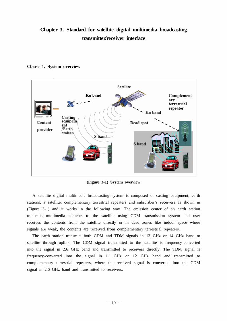
(Figure 3-1) System overview
A satellite digital multimedia broadcasting system is composed of casting equipment, earth stations, a satellite, complementary terrestrial repeaters and subscriber’s receivers as shown in (Figure 3-1) and it works in the following way. The emission center of an earth station transmits multimedia contents to the satellite using CDM transmission system and user receives the contents from the satellite directly or in dead zones like indoor space where signals are weak, the contents are received from complementary terrestrial repeaters.
The earth station transmits both CDM and TDM signals in 13 GHz or 14 GHz band to satellite through uplink. The CDM signal transmitted to the satellite is frequency-converted into the signal in 2.6 GHz band and transmitted to receivers directly. The TDM signal is frequency-converted into the signal in 11 GHz or 12 GHz band and transmitted to complementary terrestrial repeaters, where the received signal is converted into the CDM signal in 2.6 GHz band and transmitted to receivers.
- 11 -
System multiplex configuration information conforms to the configuration information of ISO/IEC 13818-1 (MPEG-2 System). Radio section between a receiver and the satellite conforms to the physical layer standard defined in ITU-R Rec. BO.1130-4. Transmission mechanism is defined in Clause 2 of Standard for Satellite Digital Multimedia Broadcasting Transmitter/Receiver Interface, and error correction code is defined in Clause 3. Interleaver, service transmission, and multiplexing and program specific information/service information are defined in Clause 4, Clause 5, and Clause 6, respectively. Audio/video encoding, CDM modulation section, and conditional access are defined in Clause 7, Clause 8, and Clause 9, respectively. Radio frequency characteristics, bit error rate performance, and the basic character set used for satellite digital multimedia broadcasting are defined in Clause 10, Clause 11, Clause 12, respectively. Finally, download service is defined in Clause 13.
Clause 2. Transmission mechanism
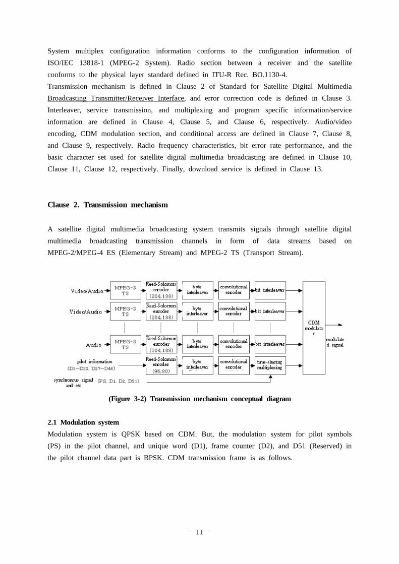
A satellite digital multimedia broadcasting system transmits signals through satellite digital multimedia broadcasting transmission channels in form of data streams based on MPEG-2/MPEG-4 ES (Elementary Stream) and MPEG-2 TS (Transport Stream).
(Figure 3-2) Transmission mechanism conceptual diagram
2.1 Modulation systemModulation system is QPSK based on CDM. But, the modulation system for pilot symbols (PS) in the pilot channel, and unique word (D1), frame counter (D2), and D51 (Reserved) in the pilot channel data part is BPSK. CDM transmission frame is as follows.
- 12 -
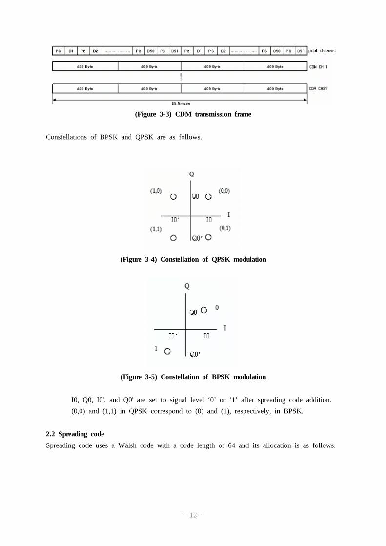
(Figure 3-3) CDM transmission frame
Constellations of BPSK and QPSK are as follows.
(Figure 3-4) Constellation of QPSK modulation
(Figure 3-5) Constellation of BPSK modulation
I0, Q0, I0', and Q0' are set to signal level ‘0’ or ‘1’ after spreading code addition.(0,0) and (1,1) in QPSK correspond to (0) and (1), respectively, in BPSK.
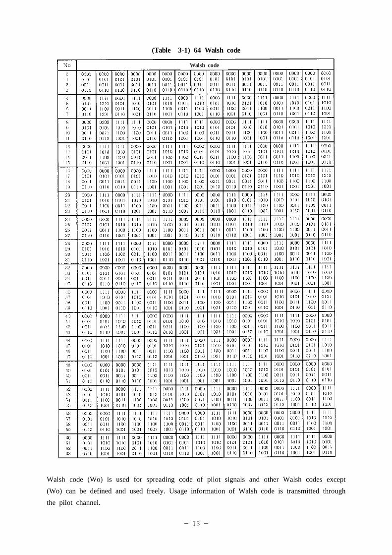
2.2 Spreading code Spreading code uses a Walsh code with a code length of 64 and its allocation is as follows.
- 13 -
(Table 3-1) 64 Walsh code
Walsh code
Walsh code (Wo) is used for spreading code of pilot signals and other Walsh codes except (Wo) can be defined and used freely. Usage information of Walsh code is transmitted through the pilot channel.
- 14 -
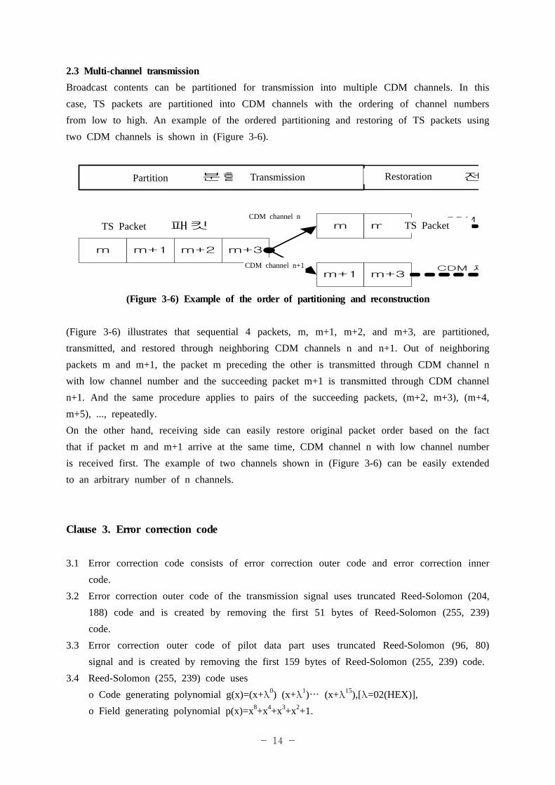
2.3 Multi-channel transmissionBroadcast contents can be partitioned for transmission into multiple CDM channels. In this case, TS packets are partitioned into CDM channels with the ordering of channel numbers from low to high. An example of the ordered partitioning and restoring of TS packets using two CDM channels is shown in (Figure 3-6).
m m+1
TS 패킷
m+2 m+3
m
m+1
m+2
m+3
분할
CDM
CDM 채
전Partition Transmission Restoration
TS Packet TS Packet
CDM channel n+1
CDM channel n
(Figure 3-6) Example of the order of partitioning and reconstruction
(Figure 3-6) illustrates that sequential 4 packets, m, m+1, m+2, and m+3, are partitioned, transmitted, and restored through neighboring CDM channels n and n+1. Out of neighboring packets m and m+1, the packet m preceding the other is transmitted through CDM channel n with low channel number and the succeeding packet m+1 is transmitted through CDM channel n+1. And the same procedure applies to pairs of the succeeding packets, (m+2, m+3), (m+4, m+5), ..., repeatedly. On the other hand, receiving side can easily restore original packet order based on the fact that if packet m and m+1 arrive at the same time, CDM channel n with low channel number is received first. The example of two channels shown in (Figure 3-6) can be easily extended to an arbitrary number of n channels.
Clause 3. Error correction code
3.1 Error correction code consists of error correction outer code and error correction inner code.
3.2 Error correction outer code of the transmission signal uses truncated Reed-Solomon (204, 188) code and is created by removing the first 51 bytes of Reed-Solomon (255, 239) code.
3.3 Error correction outer code of pilot data part uses truncated Reed-Solomon (96, 80) signal and is created by removing the first 159 bytes of Reed-Solomon (255, 239) code.
3.4 Reed-Solomon (255, 239) code useso Code generating polynomial g(x)=(x+λ0) (x+λ1)… (x+λ15),[λ=02(HEX)], o Field generating polynomial p(x)=x8+x4+x3+x2+1.
- 15 -
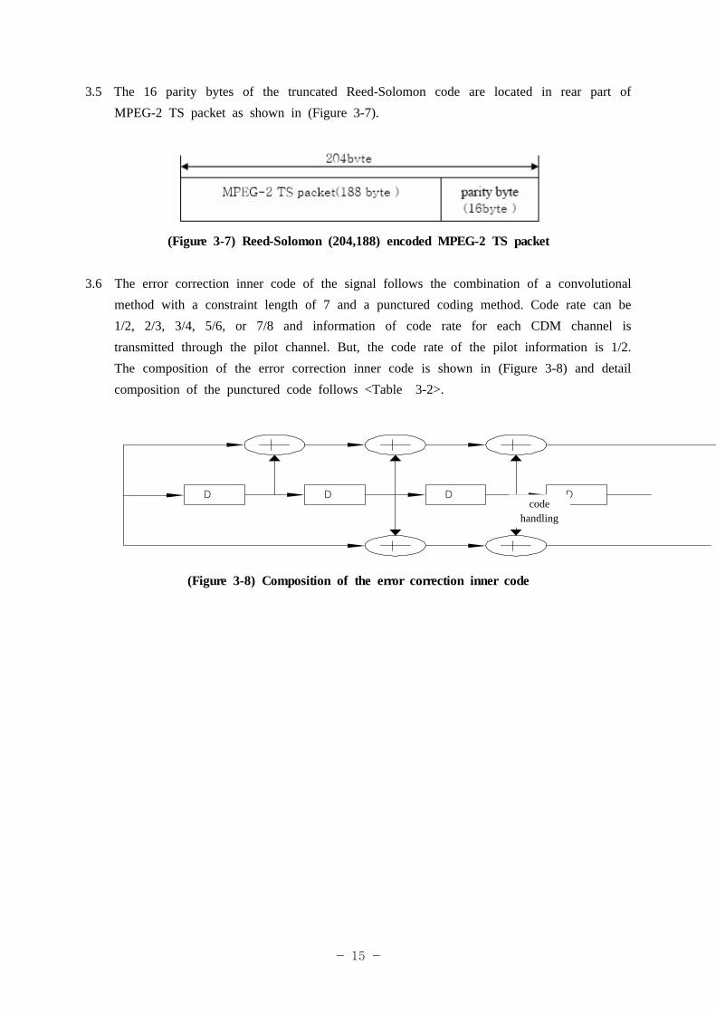
3.5 The 16 parity bytes of the truncated Reed-Solomon code are located in rear part of MPEG-2 TS packet as shown in (Figure 3-7).
(Figure 3-7) Reed-Solomon (204,188) encoded MPEG-2 TS packet
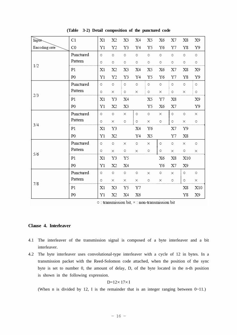
3.6 The error correction inner code of the signal follows the combination of a convolutional method with a constraint length of 7 and a punctured coding method. Code rate can be 1/2, 2/3, 3/4, 5/6, or 7/8 and information of code rate for each CDM channel is transmitted through the pilot channel. But, the code rate of the pilot information is 1/2. The composition of the error correction inner code is shown in (Figure 3-8) and detail composition of the punctured code follows <Table 3-2>.
D D D Dcode
handling
(Figure 3-8) Composition of the error correction inner code
- 16 -
(Table 3-2) Detail composition of the punctured code
Clause 4. Interleaver
4.1 The interleaver of the transmission signal is composed of a byte interleaver and a bit interleaver.
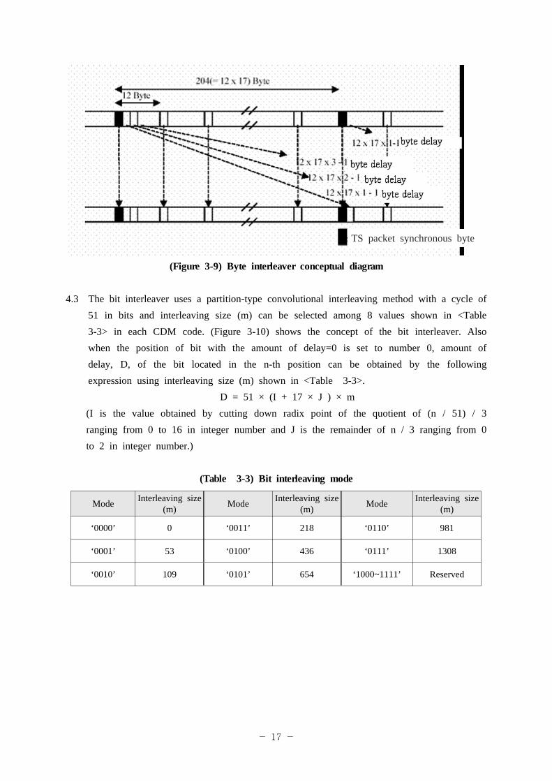
4.2 The byte interleaver uses convolutional-type interleaver with a cycle of 12 in bytes. In a transmission packet with the Reed-Solomon code attached, when the position of the sync byte is set to number 0, the amount of delay, D, of the byte located in the n-th position is shown in the following expression.
D=12×17× I (When n is divided by 12, I is the remainder that is an integer ranging between 0~11.)
- 17 -
TS packet synchronous byte
(Figure 3-9) Byte interleaver conceptual diagram
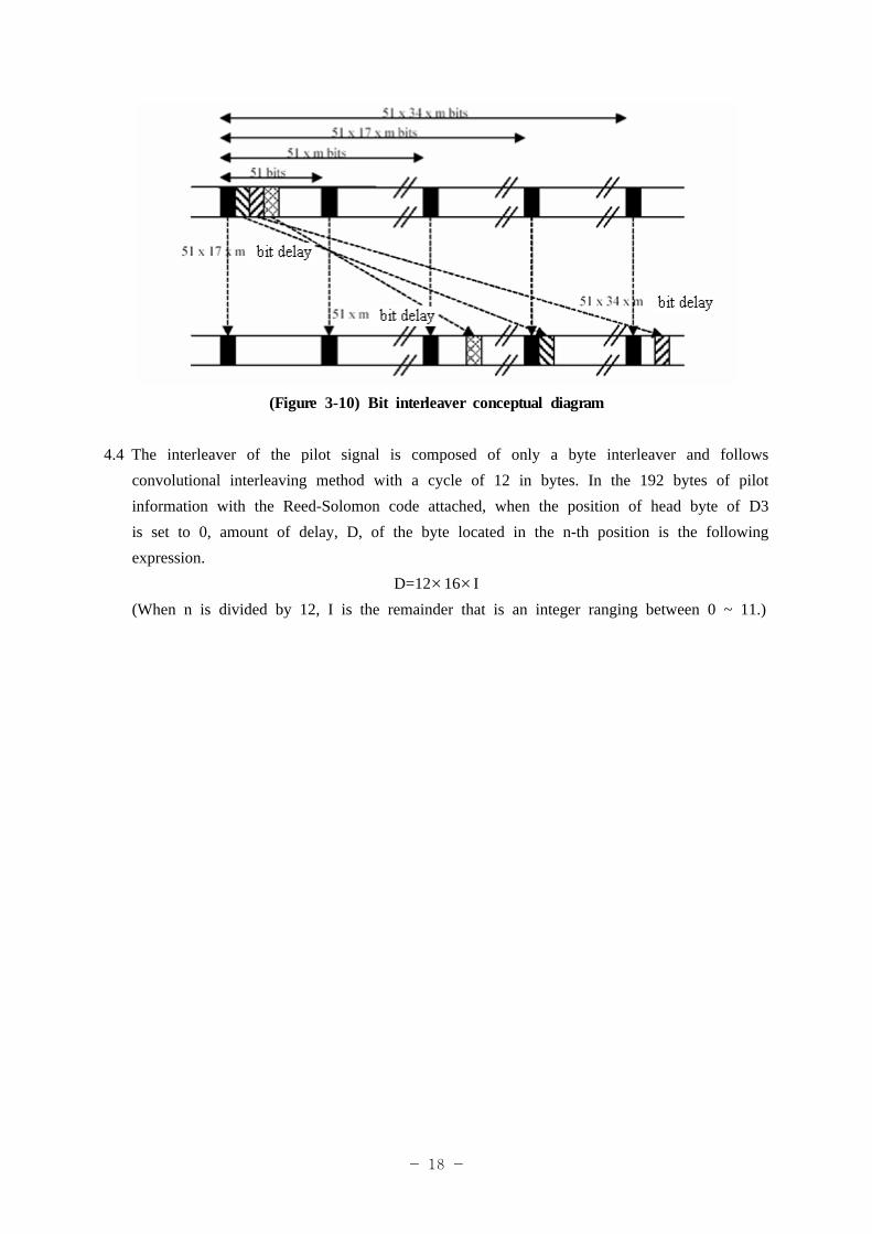
4.3 The bit interleaver uses a partition-type convolutional interleaving method with a cycle of 51 in bits and interleaving size (m) can be selected among 8 values shown in <Table 3-3> in each CDM code. (Figure 3-10) shows the concept of the bit interleaver. Also when the position of bit with the amount of delay=0 is set to number 0, amount of delay, D, of the bit located in the n-th position can be obtained by the following expression using interleaving size (m) shown in <Table 3-3>.
D = 51 × (I + 17 × J ) × m(I is the value obtained by cutting down radix point of the quotient of (n / 51) / 3 ranging from 0 to 16 in integer number and J is the remainder of n / 3 ranging from 0 to 2 in integer number.)
(Table 3-3) Bit interleaving mode
Mode Interleaving size (m) Mode Interleaving size
(m) Mode Interleaving size (m)
‘0000’ 0 ‘0011’ 218 ‘0110’ 981
‘0001’ 53 ‘0100’ 436 ‘0111’ 1308
‘0010’ 109 ‘0101’ 654 ‘1000~1111’ Reserved
- 18 -
(Figure 3-10) Bit interleaver conceptual diagram
4.4 The interleaver of the pilot signal is composed of only a byte interleaver and follows convolutional interleaving method with a cycle of 12 in bytes. In the 192 bytes of pilot information with the Reed-Solomon code attached, when the position of head byte of D3 is set to 0, amount of delay, D, of the byte located in the n-th position is the following expression.
D=12×16× I (When n is divided by 12, I is the remainder that is an integer ranging between 0 ~ 11.)
- 19 -
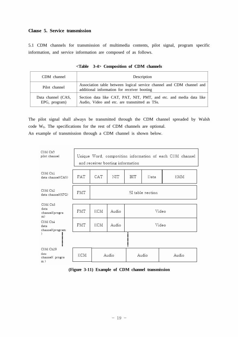
Clause 5. Service transmission
5.1 CDM channels for transmission of multimedia contents, pilot signal, program specific information, and service information are composed of as follows.
<Table 3-4> Composition of CDM channels
CDM channel Description
Pilot channel Association table between logical service channel and CDM channel and additional information for receiver booting
Data channel (CAS, EPG, program)
Section data like CAT, PAT, NIT, PMT, and etc. and media data like Audio, Video and etc. are transmitted as TSs.
The pilot signal shall always be transmitted through the CDM channel spreaded by Walsh code W0. The specifications for the rest of CDM channels are optional.An example of transmission through a CDM channel is shown below.
data
(Figure 3-11) Example of CDM channel transmission
- 20 -
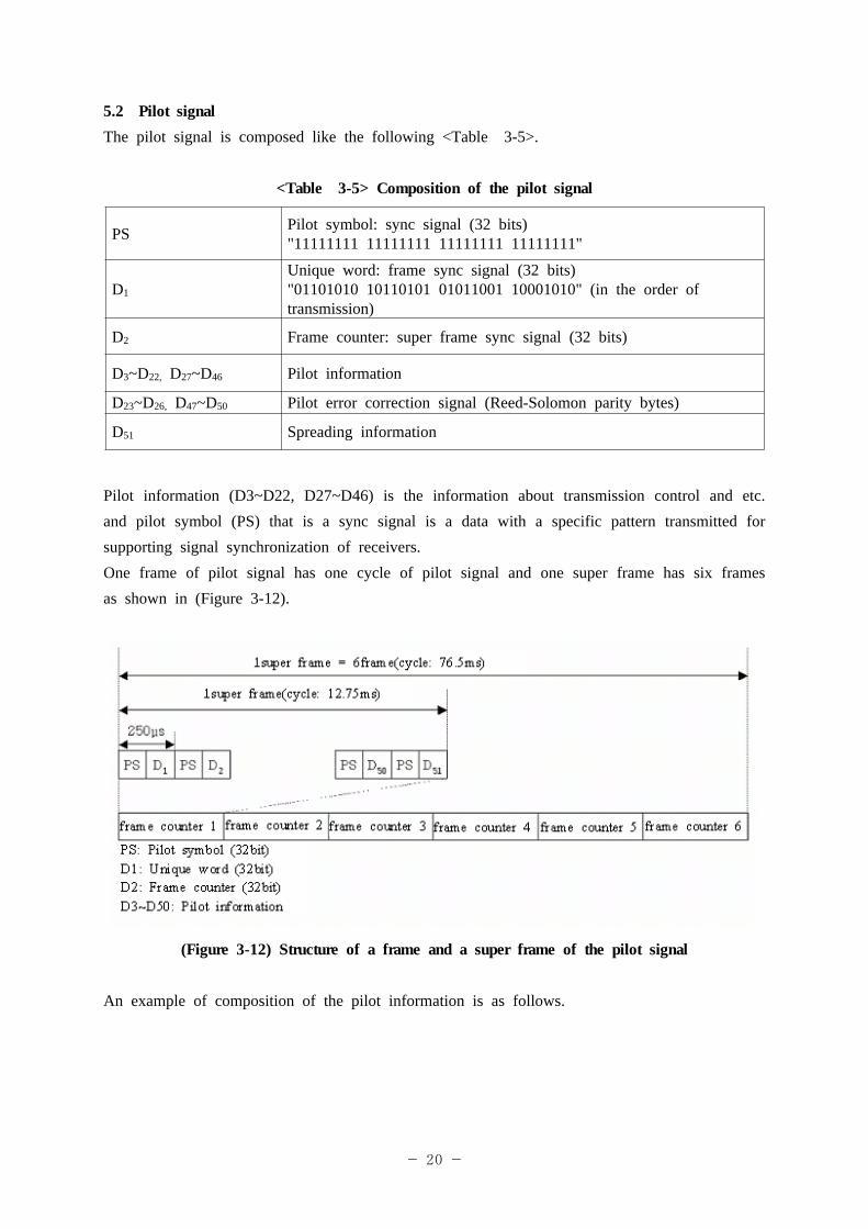
5.2 Pilot signalThe pilot signal is composed like the following <Table 3-5>.
<Table 3-5> Composition of the pilot signal
PS Pilot symbol: sync signal (32 bits)"11111111 11111111 11111111 11111111"
D1
Unique word: frame sync signal (32 bits)"01101010 10110101 01011001 10001010" (in the order of transmission)
D2 Frame counter: super frame sync signal (32 bits)
D3~D22, D27~D46 Pilot information
D23~D26, D47~D50 Pilot error correction signal (Reed-Solomon parity bytes)
D51 Spreading information
Pilot information (D3~D22, D27~D46) is the information about transmission control and etc. and pilot symbol (PS) that is a sync signal is a data with a specific pattern transmitted for supporting signal synchronization of receivers.One frame of pilot signal has one cycle of pilot signal and one super frame has six frames as shown in (Figure 3-12).
(Figure 3-12) Structure of a frame and a super frame of the pilot signal
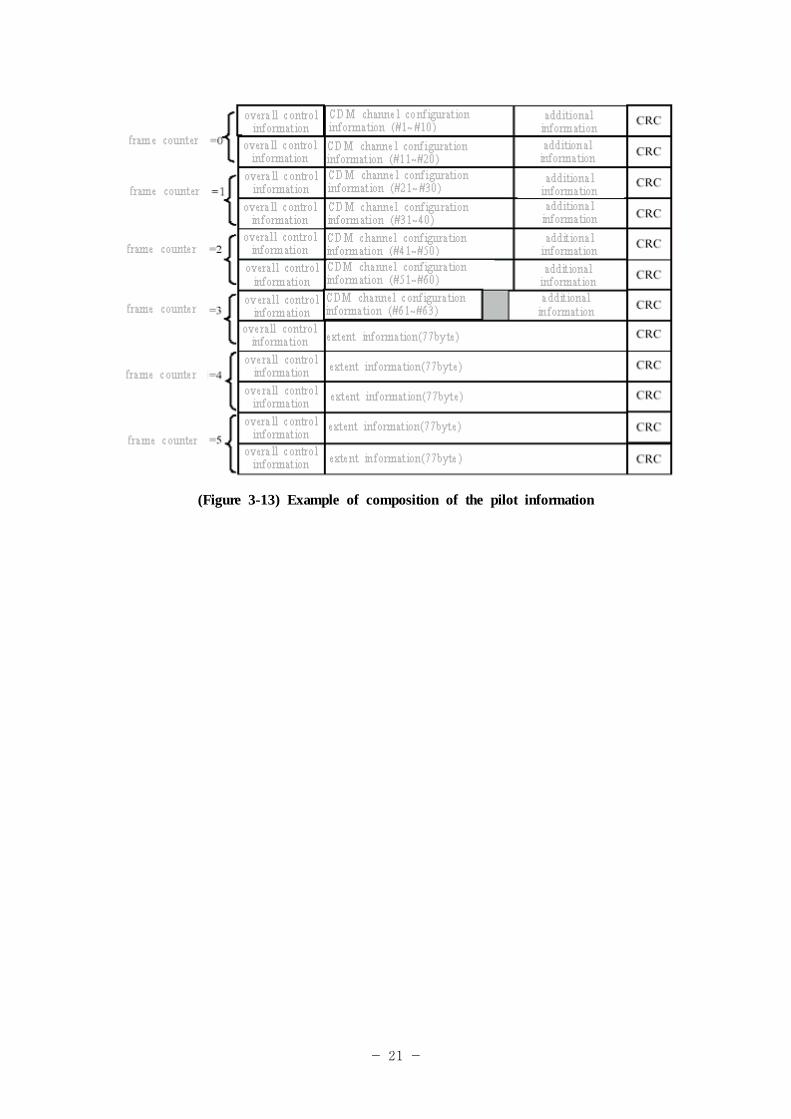
An example of composition of the pilot information is as follows.
- 21 -
(Figure 3-13) Example of composition of the pilot information
- 22 -
Clause 6. Multiplexing and program specific information / service information
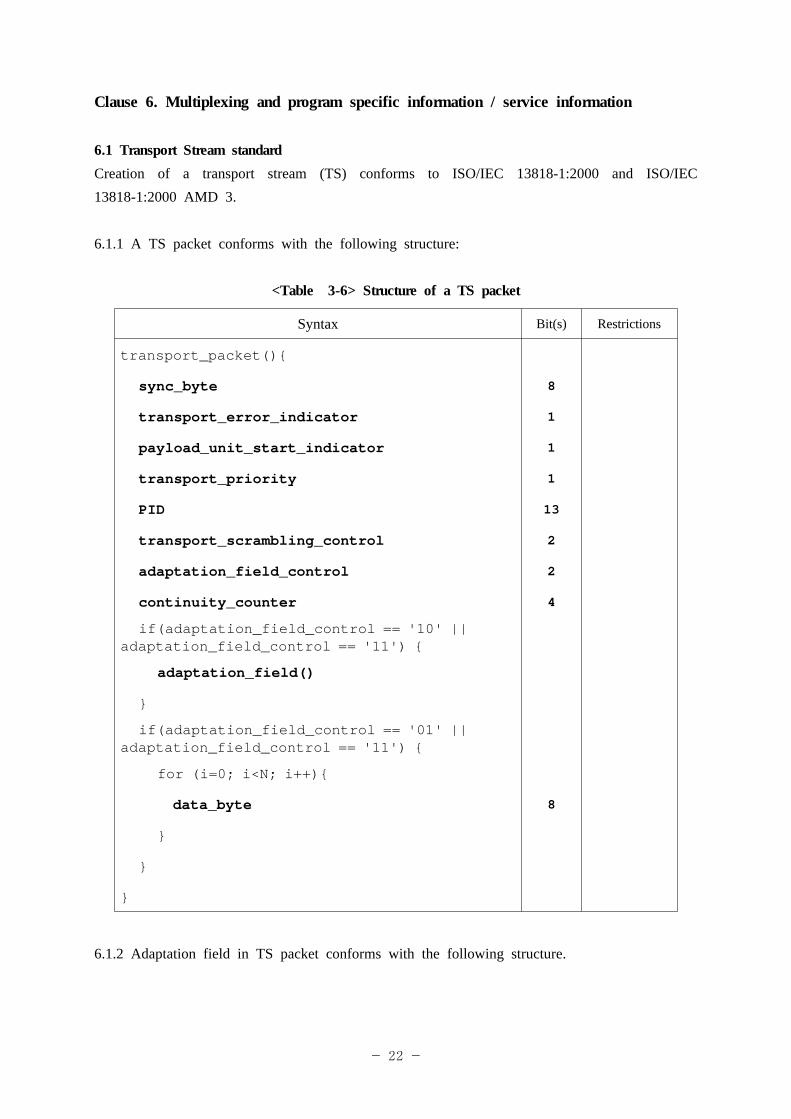
6.1 Transport Stream standard Creation of a transport stream (TS) conforms to ISO/IEC 13818-1:2000 and ISO/IEC 13818-1:2000 AMD 3.
6.1.1 A TS packet conforms with the following structure:
<Table 3-6> Structure of a TS packet
Syntax Bit(s) Restrictions
transport_packet(){
sync_byte 8
transport_error_indicator 1
payload_unit_start_indicator 1
transport_priority 1
PID 13
transport_scrambling_control 2
adaptation_field_control 2
continuity_counter 4
if(adaptation_field_control == '10' || adaptation_field_control == '11') {
adaptation_field()
}
if(adaptation_field_control == '01' || adaptation_field_control == '11') {
for (i=0; i<N; i++){
data_byte 8
}
}
}
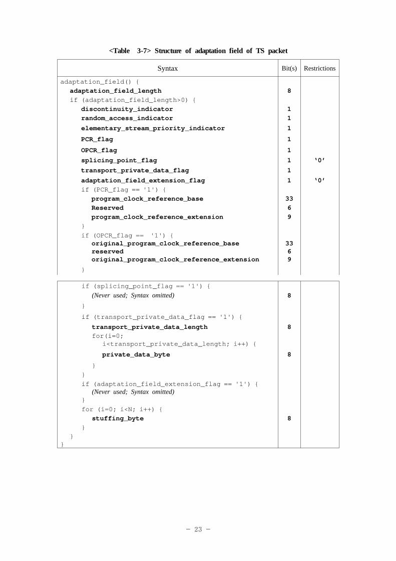
6.1.2 Adaptation field in TS packet conforms with the following structure.
- 23 -
<Table 3-7> Structure of adaptation field of TS packet
Syntax Bit(s) Restrictions
adaptation_field() {adaptation_field_length 8if (adaptation_field_length>0) {
discontinuity_indicator 1random_access_indicator 1
elementary_stream_priority_indicator 1
PCR_flag 1
OPCR_flag 1
splicing_point_flag 1 ‘0’
transport_private_data_flag 1
adaptation_field_extension_flag 1 ‘0’if (PCR_flag == '1') {
program_clock_reference_base 33Reserved 6program_clock_reference_extension 9
}if (OPCR_flag == '1') {
original_program_clock_reference_basereservedoriginal_program_clock_reference_extension
3369
}
if (splicing_point_flag == '1') {(Never used; Syntax omitted) 8
}
if (transport_private_data_flag == '1') {
transport_private_data_length 8for(i=0;
i<transport_private_data_length; i++) {
private_data_byte 8
}}if (adaptation_field_extension_flag == '1') {
(Never used; Syntax omitted) } for (i=0; i<N; i++) { stuffing_byte 8 }
}}
- 24 -
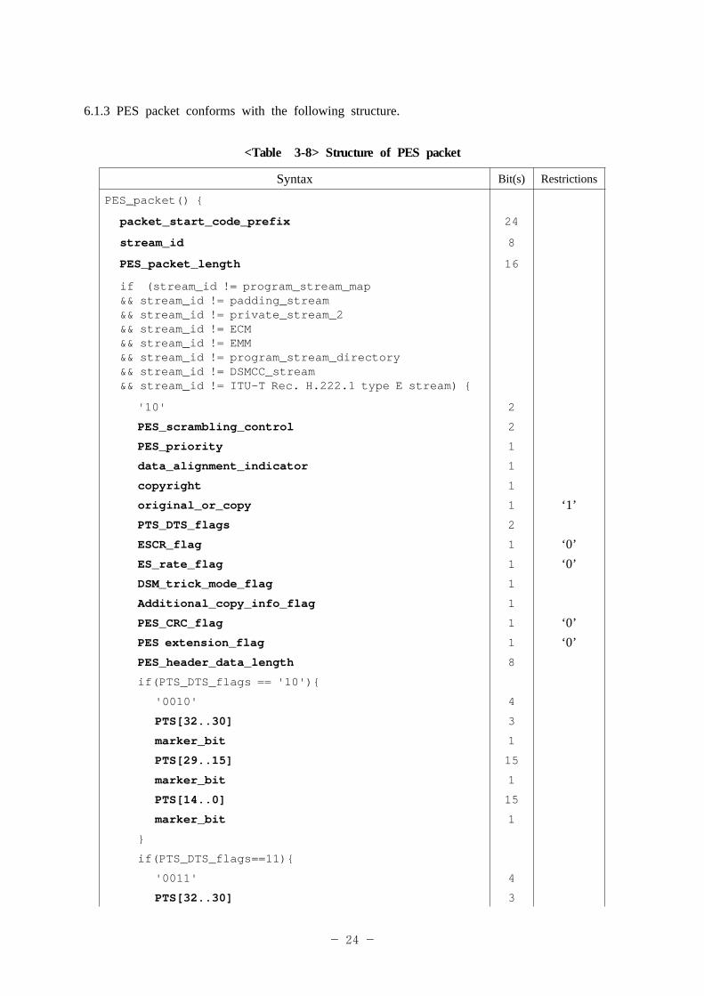
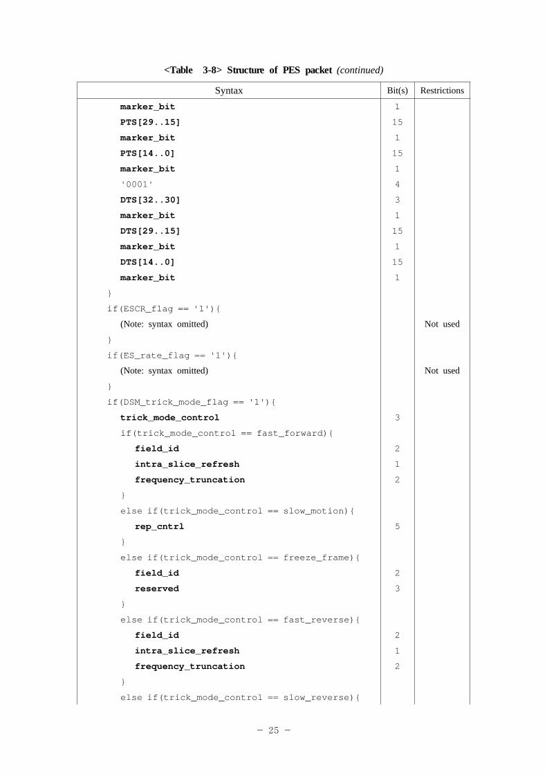
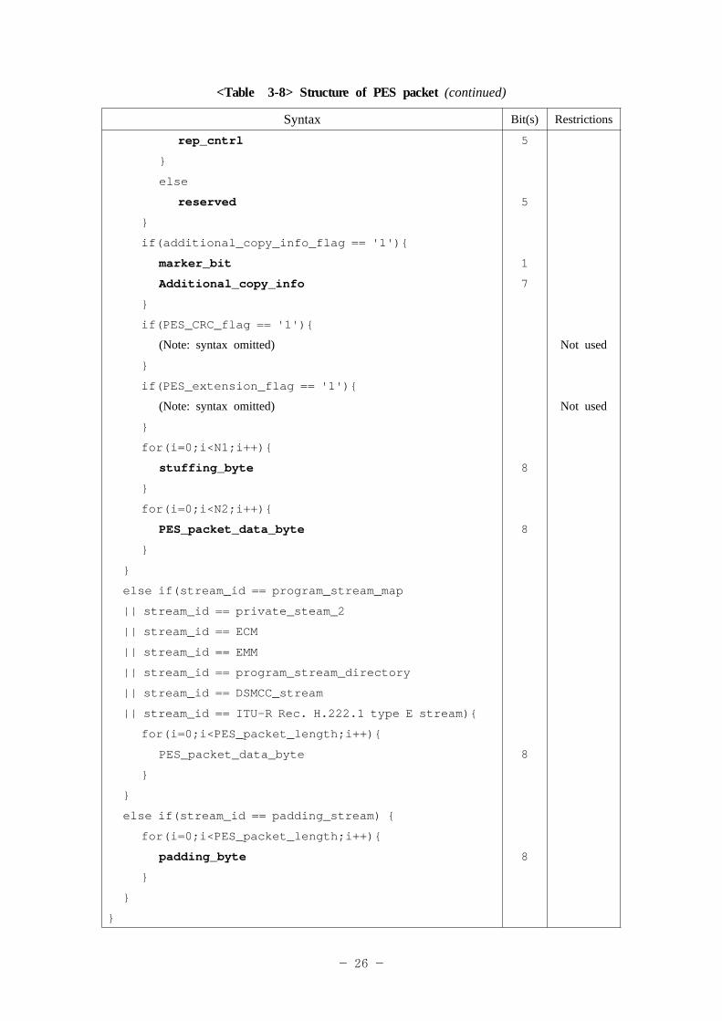
6.1.3 PES packet conforms with the following structure.
<Table 3-8> Structure of PES packet
Syntax Bit(s) Restrictions
PES_packet() {
packet_start_code_prefix 24
stream_id 8
PES_packet_length 16
if (stream_id != program_stream_map && stream_id != padding_stream && stream_id != private_stream_2 && stream_id != ECM && stream_id != EMM&& stream_id != program_stream_directory && stream_id != DSMCC_stream&& stream_id != ITU-T Rec. H.222.1 type E stream) {
'10' 2
PES_scrambling_control 2
PES_priority 1
data_alignment_indicator 1
copyright 1
original_or_copy 1 ‘1’PTS_DTS_flags 2
ESCR_flag 1 ‘0’ES_rate_flag 1 ‘0’DSM_trick_mode_flag 1
Additional_copy_info_flag 1
PES_CRC_flag 1 ‘0’PES extension_flag 1 ‘0’PES_header_data_length 8
if(PTS_DTS_flags == '10'){
'0010' 4
PTS[32..30] 3
marker_bit 1
PTS[29..15] 15
marker_bit 1
PTS[14..0] 15
marker_bit 1
}
if(PTS_DTS_flags==11){
'0011' 4
PTS[32..30] 3
- 25 -
<Table 3-8> Structure of PES packet (continued)
Syntax Bit(s) Restrictions
marker_bit 1
PTS[29..15] 15
marker_bit 1
PTS[14..0] 15
marker_bit 1
'0001' 4
DTS[32..30] 3
marker_bit 1
DTS[29..15] 15
marker_bit 1
DTS[14..0] 15
marker_bit 1
}
if(ESCR_flag == '1'){
(Note: syntax omitted) Not used
}
if(ES_rate_flag == '1'){
(Note: syntax omitted) Not used
}
if(DSM_trick_mode_flag == '1'){
trick_mode_control 3
if(trick_mode_control == fast_forward){
field_id 2
intra_slice_refresh 1
frequency_truncation 2
}
else if(trick_mode_control == slow_motion){
rep_cntrl 5
}
else if(trick_mode_control == freeze_frame){
field_id 2
reserved 3
}
else if(trick_mode_control == fast_reverse){
field_id 2
intra_slice_refresh 1
frequency_truncation 2
}
else if(trick_mode_control == slow_reverse){
- 26 -
<Table 3-8> Structure of PES packet (continued)
Syntax Bit(s) Restrictions
rep_cntrl 5
}
else
reserved 5
}
if(additional_copy_info_flag == '1'){
marker_bit 1
Additional_copy_info 7
}
if(PES_CRC_flag == '1'){
(Note: syntax omitted) Not used
}
if(PES_extension_flag == '1'){
(Note: syntax omitted) Not used
}
for(i=0;i<N1;i++){
stuffing_byte 8
}
for(i=0;i<N2;i++){
PES_packet_data_byte 8
}
}
else if(stream_id == program_stream_map
|| stream_id == private_steam_2
|| stream_id == ECM
|| stream_id == EMM
|| stream_id == program_stream_directory
|| stream_id == DSMCC_stream
|| stream_id == ITU-R Rec. H.222.1 type E stream){
for(i=0;i<PES_packet_length;i++){
PES_packet_data_byte 8
}
}
else if(stream_id == padding_stream) {
for(i=0;i<PES_packet_length;i++){
padding_byte 8
}
}
}
- 27 -
6.1.4 Time StampTime stamps related to H.264 and AAC are based on Presentation Time Stamp (PTS) in Packetized Elementary Stream (PES) header. Transmission of time stamps using H.264 Video Usability Information (VUI) is optional and in this case, 90 KHz clock reference is used. In case of AAC, omission of audio frame is not permitted.6.1.5 Access unitAccess unit of H.264 coded stream follows the definition of ISO/IEC 13818-1:2000 AMD 3 but SPS and PPS are transmitted between access unit delimiter and primary coded picture. Also SPS (Sequence Parameter Set) and PPS (Picture Parameter Set) should be transmitted for every IDR.
6.1.6 H.264 coded stream should satisfy the following conditions for byte stream NAL format defined in Annex B in MPEG, ISO/IEC 14496-10:2003(E).- Access unit delimiter NAL unit should have a single zero_byte. So access unit delimiter should start with 0x00000001.- VUI isn’t used.
6.1.7 H.264 related TS standardAn H.264 related descriptor shall use AVC_video_descriptor() and data_stream_alignment_descriptor() and can use H264_descriptor() as an option. All these descriptors are included and transmitted in video elementary stream (ES) information of corresponding program within Program Map Table(PMT).
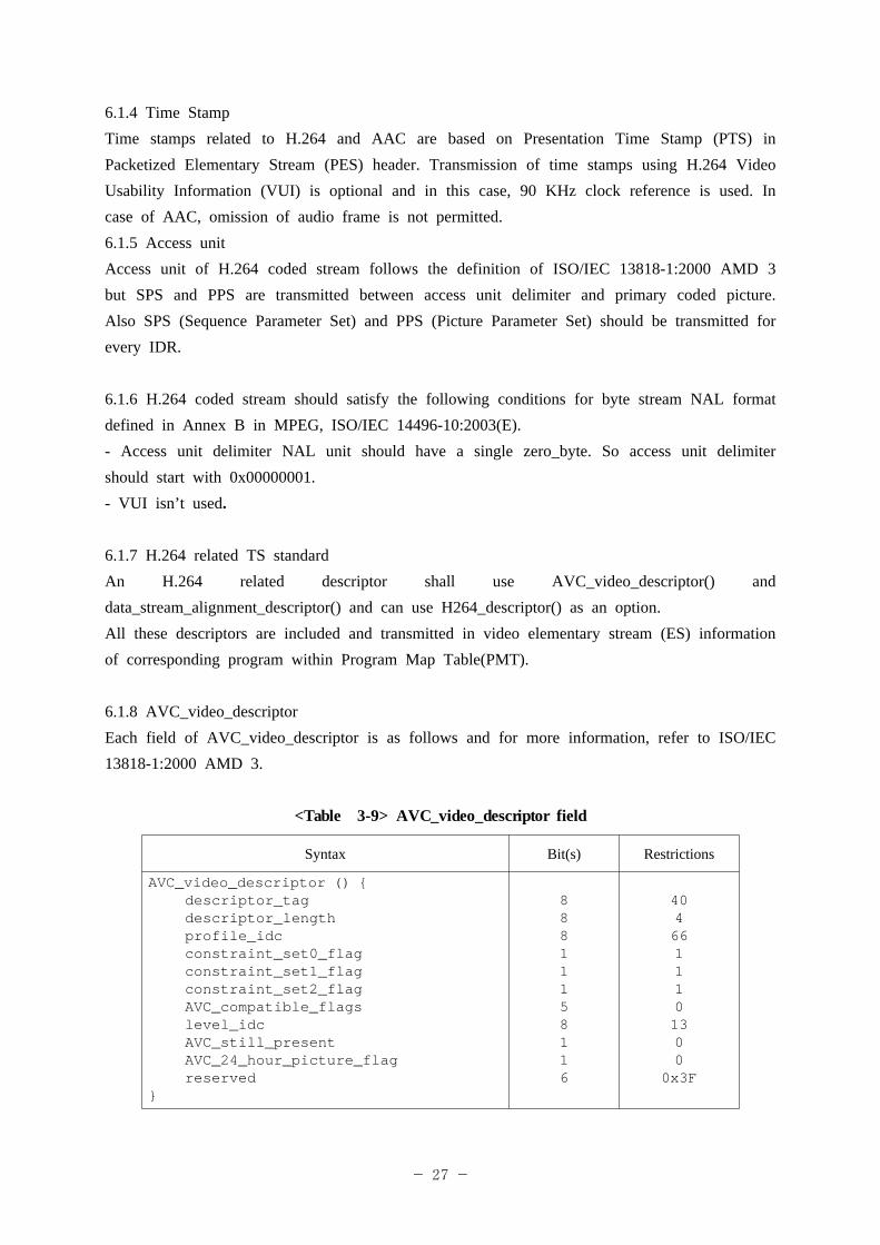
6.1.8 AVC_video_descriptorEach field of AVC_video_descriptor is as follows and for more information, refer to ISO/IEC 13818-1:2000 AMD 3.
<Table 3-9> AVC_video_descriptor field
Syntax Bit(s) Restrictions
AVC_video_descriptor () { descriptor_tag descriptor_length profile_idc constraint_set0_flag constraint_set1_flag constraint_set2_flag AVC_compatible_flags level_idc AVC_still_present AVC_24_hour_picture_flag reserved
}
88811158116
4046611101300
0x3F
- 28 -
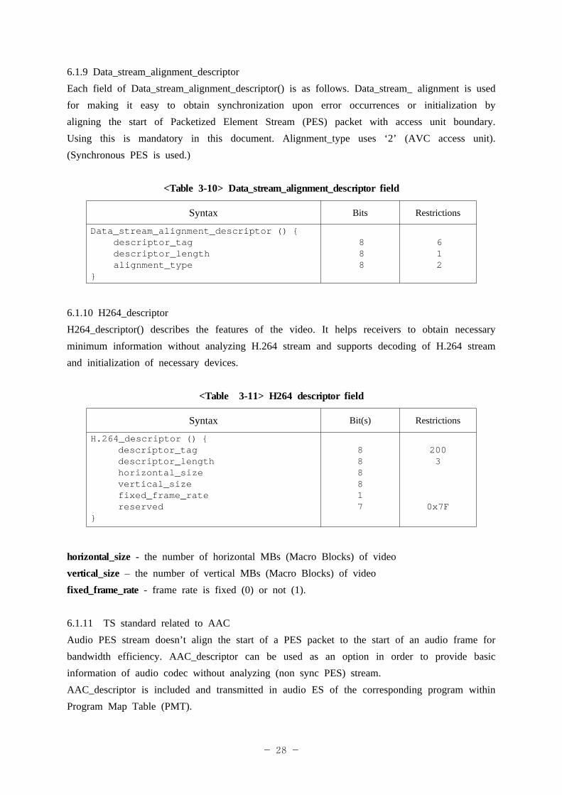
6.1.9 Data_stream_alignment_descriptorEach field of Data_stream_alignment_descriptor() is as follows. Data_stream_ alignment is used for making it easy to obtain synchronization upon error occurrences or initialization by aligning the start of Packetized Element Stream (PES) packet with access unit boundary. Using this is mandatory in this document. Alignment_type uses ‘2’ (AVC access unit). (Synchronous PES is used.)
<Table 3-10> Data_stream_alignment_descriptor field
Syntax Bits Restrictions
Data_stream_alignment_descriptor () { descriptor_tag descriptor_length alignment_type
}
888
612
6.1.10 H264_descriptorH264_descriptor() describes the features of the video. It helps receivers to obtain necessary minimum information without analyzing H.264 stream and supports decoding of H.264 stream and initialization of necessary devices.
<Table 3-11> H264 descriptor field
Syntax Bit(s) Restrictions
H.264_descriptor () {descriptor_tagdescriptor_lengthhorizontal_sizevertical_sizefixed_frame_ratereserved
}
888817
2003
0x7F
horizontal_size - the number of horizontal MBs (Macro Blocks) of videovertical_size – the number of vertical MBs (Macro Blocks) of videofixed_frame_rate - frame rate is fixed (0) or not (1).
6.1.11 TS standard related to AACAudio PES stream doesn’t align the start of a PES packet to the start of an audio frame for bandwidth efficiency. AAC_descriptor can be used as an option in order to provide basic information of audio codec without analyzing (non sync PES) stream.AAC_descriptor is included and transmitted in audio ES of the corresponding program within Program Map Table (PMT).
- 29 -
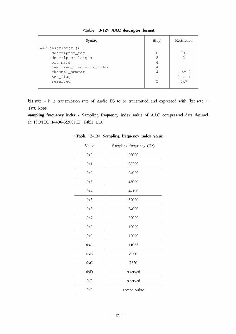
<Table 3-12> AAC_descriptor format
Syntax Bit(s) Restriction
AAC_descriptor () {descriptor_tagdescriptor_lengthbit ratesampling_frequency_indexchannel_numberSBR_flagreserved
}
8844413
2012
1 or 20 or 10x7
bit_rate – it is transmission rate of Audio ES to be transmitted and expressed with (bit_rate + 1)*8 kbps.sampling_frequency_index - Sampling frequency index value of AAC compressed data defined in ISO/IEC 14496-3:2001(E) Table 1.10.
<Table 3-13> Sampling frequency index value
Value Sampling frequency (Hz)
0x0 96000
0x1 88200
0x2 64000
0x3 48000
0x4 44100
0x5 32000
0x6 24000
0x7 22050
0x8 16000
0x9 12000
0xA 11025
0xB 8000
0xC 7350
0xD reserved
0xE reserved
0xF escape value

- 30 -
channel_number: the number of channels 0 : mono1: stereo2: dual mono3: surround 5.1
SBR_flag: flag indicating audio codec in use.0 : AAC1 : AAC + SBR
6.2 Program Specific Information & Service Information6.2.1 Scope It is applied to structure, kinds of signal, basic data structure and operation of identifier of program specific information and service information used for satellite digital multimedia broadcasting.
6.2.2 ExtensibilityIf you want to use service information (SI) and descriptor that are not defined in this standard, you can operate new tables and descriptors using Private Section Syntax and User Private defined in ISO/IEC 13818-1:2000.
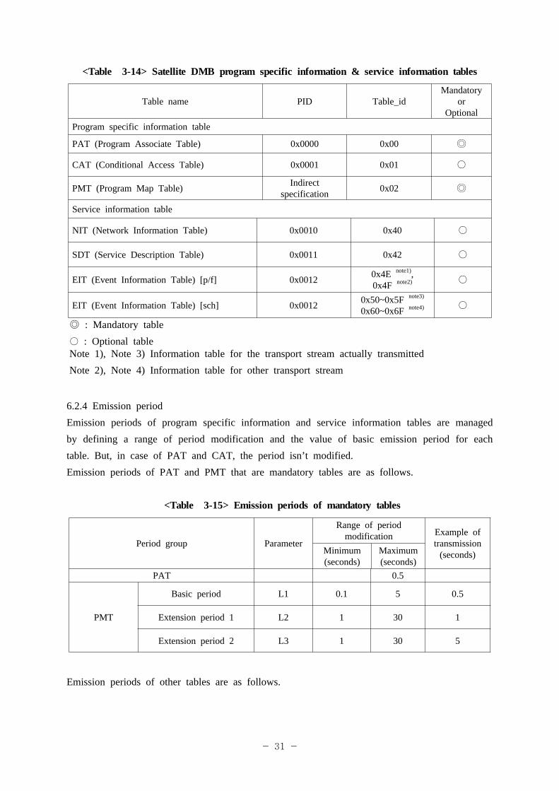
6.2.3 Program specific information & service information tables used for satellite digital multimedia broadcasting are as follows.
- 31 -
<Table 3-14> Satellite DMB program specific information & service information tables
Table name PID Table_idMandatory
orOptional
Program specific information table
PAT (Program Associate Table) 0x0000 0x00 ◎
CAT (Conditional Access Table) 0x0001 0x01 ○
PMT (Program Map Table) Indirect specification 0x02 ◎
Service information table
NIT (Network Information Table) 0x0010 0x40 ○
SDT (Service Description Table) 0x0011 0x42 ○
EIT (Event Information Table) [p/f] 0x0012 0x4E note1),0x4F note2) ○
EIT (Event Information Table) [sch] 0x0012 0x50~0x5F note3)
0x60~0x6F note4) ○
◎ : Mandatory table○ : Optional tableNote 1), Note 3) Information table for the transport stream actually transmitted Note 2), Note 4) Information table for other transport stream
6.2.4 Emission period Emission periods of program specific information and service information tables are managed by defining a range of period modification and the value of basic emission period for each table. But, in case of PAT and CAT, the period isn’t modified.Emission periods of PAT and PMT that are mandatory tables are as follows.
<Table 3-15> Emission periods of mandatory tables
Period group Parameter
Range of period modification Example of
transmission (seconds)Minimum
(seconds)Maximum (seconds)
PAT 0.5
PMT
Basic period L1 0.1 5 0.5
Extension period 1 L2 1 30 1
Extension period 2 L3 1 30 5
Emission periods of other tables are as follows.
- 32 -
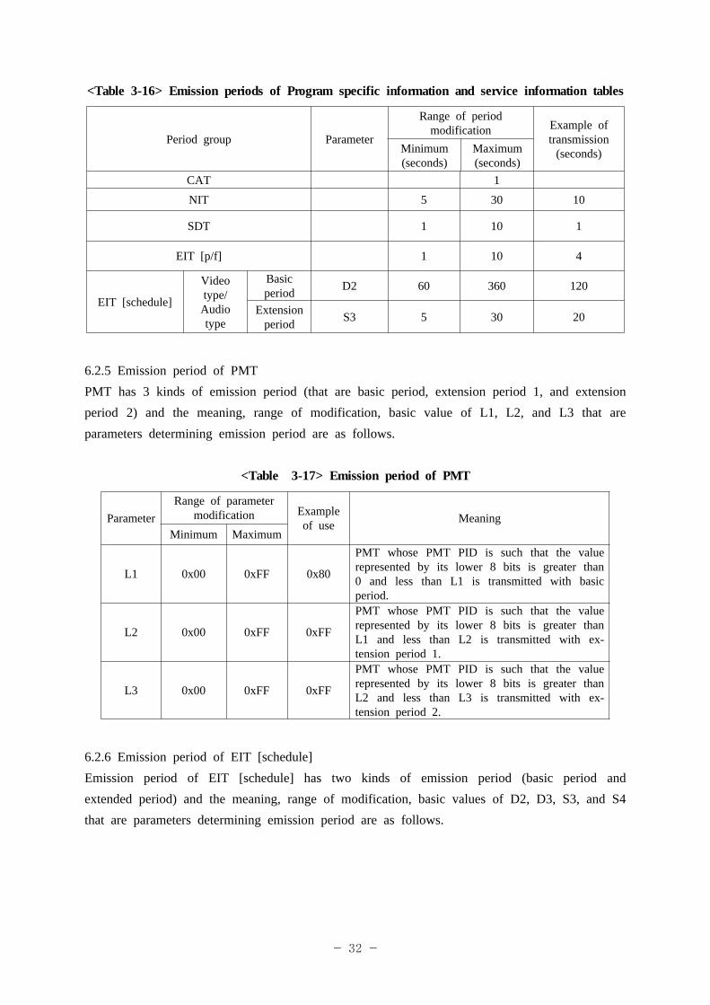
<Table 3-16> Emission periods of Program specific information and service information tables
Period group Parameter
Range of period modification Example of
transmission (seconds)Minimum
(seconds)Maximum (seconds)
CAT 1
NIT 5 30 10
SDT 1 10 1
EIT [p/f] 1 10 4
EIT [schedule]
Video type/
Audio type
Basic period D2 60 360 120
Extension period S3 5 30 20
6.2.5 Emission period of PMTPMT has 3 kinds of emission period (that are basic period, extension period 1, and extension period 2) and the meaning, range of modification, basic value of L1, L2, and L3 that are parameters determining emission period are as follows.
<Table 3-17> Emission period of PMT
ParameterRange of parameter
modification Example of use Meaning
Minimum Maximum
L1 0x00 0xFF 0x80
PMT whose PMT PID is such that the value represented by its lower 8 bits is greater than 0 and less than L1 is transmitted with basic period.
L2 0x00 0xFF 0xFF
PMT whose PMT PID is such that the value represented by its lower 8 bits is greater than L1 and less than L2 is transmitted with ex-tension period 1.
L3 0x00 0xFF 0xFF
PMT whose PMT PID is such that the value represented by its lower 8 bits is greater than L2 and less than L3 is transmitted with ex-tension period 2.
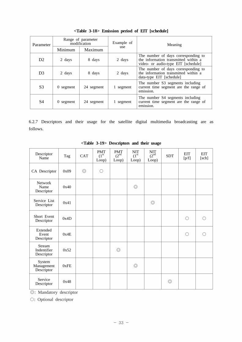
6.2.6 Emission period of EIT [schedule]Emission period of EIT [schedule] has two kinds of emission period (basic period and extended period) and the meaning, range of modification, basic values of D2, D3, S3, and S4 that are parameters determining emission period are as follows.
- 33 -
<Table 3-18> Emission period of EIT [schedule]
ParameterRange of parameter
modification Example of use Meaning
Minimum Maximum
D2 2 days 8 days 2 daysThe number of days corresponding to the information transmitted within a video- or audio-type EIT [schedule]
D3 2 days 8 days 2 daysThe number of days corresponding to the information transmitted within a data-type EIT [schedule]
S3 0 segment 24 segment 1 segmentThe number S3 segments including current time segment are the range of emission.
S4 0 segment 24 segment 1 segmentThe number S4 segments including current time segment are the range of emission.
6.2.7 Descriptors and their usage for the satellite digital multimedia broadcasting are as follows.
<Table 3-19> Descriptors and their usage
Descriptor Name Tag CAT
PMT(1st
Loop)
PMT(2nd
Loop)
NIT (1st
Loop)
NIT (2nd
Loop)SDT EIT
[p/f]EIT[sch]
CA Descriptor 0x09 ◎ ○
Network Name
Descriptor0x40 ◎
Service ListDescriptor 0x41 ◎
Short Event Descriptor 0x4D ○ ○
Extended Event
Descriptor0x4E ○ ○
Stream IndentifierDescriptor
0x52 ◎System
Management Descriptor
0xFE ◎
Service Descriptor 0x48 ◎
◎: Mandatory descriptor○: Optional descriptor
- 34 -
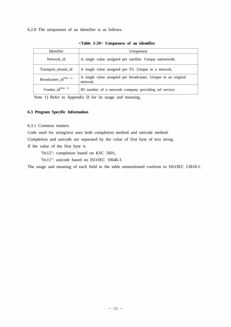
6.2.8 The uniqueness of an identifier is as follows.
<Table 3-20> Uniqueness of an identifier
Identifier Uniqueness
Network_id A single value assigned per satellite. Unique nationwide.
Transport_stream_id A single value assigned per TS. Unique in a network.
Broadcaster_idNote 1) A single value assigned per broadcaster. Unique in an original network.
Vendor_idNote 1) ID number of a network company providing url service.
Note 1) Refer to Appendix D for its usage and meaning.
6.3 Program Specific Information
6.3.1 Common mattersCode used for string/text uses both completion method and unicode method.Completion and unicode are separated by the value of first byte of text string.If the value of the first byte is
"0x12": completion based on KSC 5601,"0x11": unicode based on ISO/IEC 10646-1.
The usage and meaning of each field in the table unmentioned conform to ISO/IEC 13818-1.
- 35 -
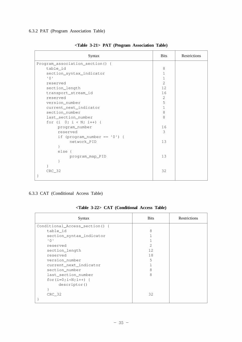
6.3.2 PAT (Program Association Table)
<Table 3-21> PAT (Program Association Table)
Syntax Bits Restrictions
Program_association_section() {table_id
section_syntax_indicator '0'
reserved section_length transport_stream_id reserved version_number current_next_indicator section_number last_section_number for (i 0; i < N; i++) { program_number reserved if (program_number == '0') { network_PID } else { program_map_PID } } CRC_32}
8112121625188
163
13
13
32
6.3.3 CAT (Conditional Access Table)
<Table 3-22> CAT (Conditional Access Table)
Syntax Bits Restrictions
Conditional_Access_section() {table_idsection_syntax_indicator'0'reservedsection_lengthreservedversion_numbercurrent_next_indicatorsection_numberlast_section_numberfor(i=0;i<N;i++) {
descriptor()}CRC_32
}
811212185188
32
- 36 -
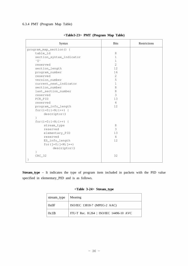
6.3.4 PMT (Program Map Table)
<Table3-23> PMT (Program Map Table)
Syntax Bits Restrictions
program_map_section() {table_idsection_syntax_indicator'0'reservedsection_lengthprogram_numberreservedversion_numbercurrent_next_indicatorsection_numberlast_section_numberreservedPCR_PIDreservedprogram_info_lengthfor(i=0;i<N;i++) {
descriptor()}for(i=0;i<N;i++) {
stream_typereservedelementary_PIDreservedES_info_lengthfor(j=0;j<M;j++)
descriptor()}CRC_32
}
8112121625188313412
8313412
32
Stream_type – It indicates the type of program item included in packets with the PID value specified in elementary_PID and is as follows.
<Table 3-24> Stream_type
stream_type Meaning
0x0F ISO/IEC 13818-7 (MPEG-2 AAC)
0x1B ITU-T Rec. H.264 | ISO/IEC 14496-10 AVC
- 37 -
6.4 Service information (Service Information)6.4.1 Common mattersCode used for string/text uses both completion method and unicode method.Completion and unicode are separated by the value of first byte of text string.If the value of the first byte is
"0x12": completion based on KSC 5601,"0x11": unicode based on ISO/IEC 10646-1.
The usage and meaning of each field in the table unmentioned conform to EN 300 468, Digital Video Broadcasting (DVB); Specification for Service Information (SI) in DVB Systems.
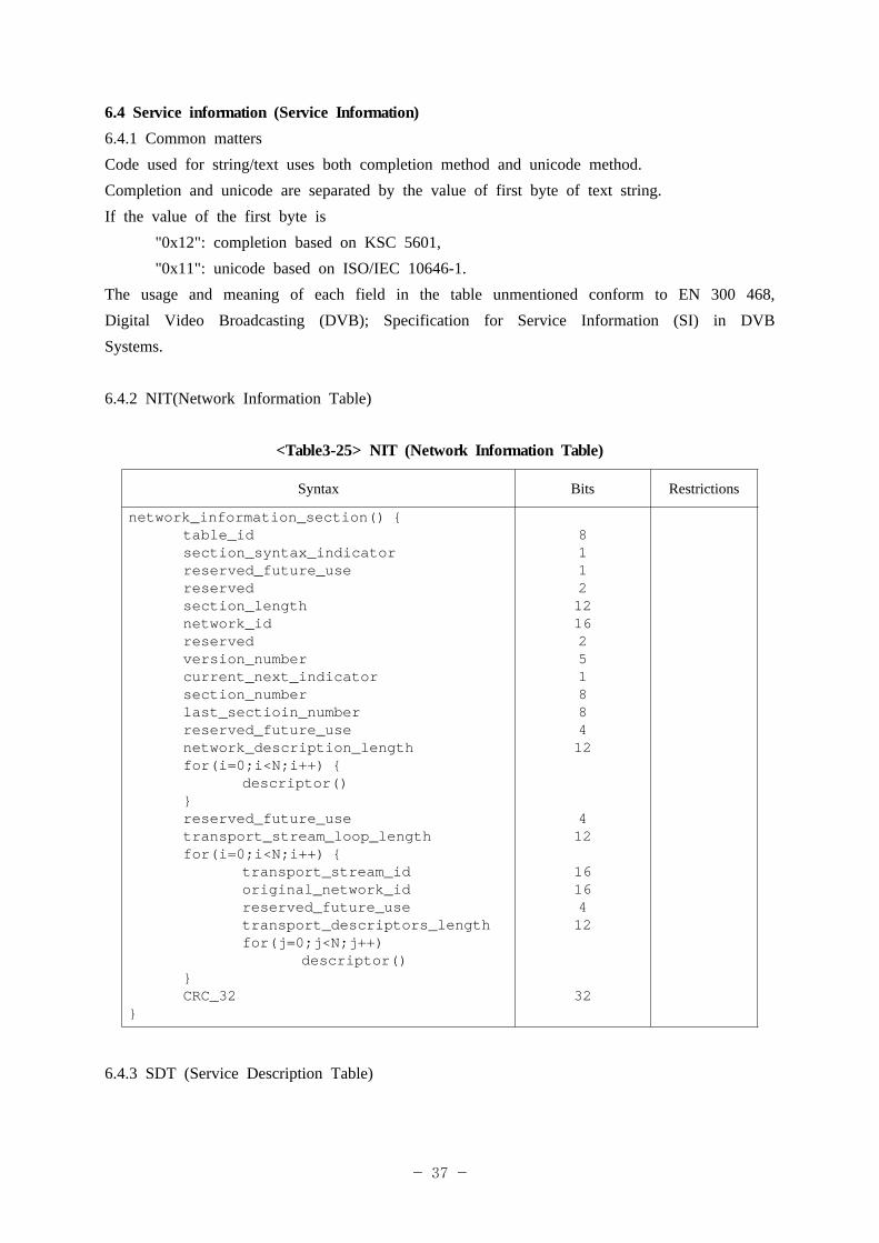
6.4.2 NIT(Network Information Table)
<Table3-25> NIT (Network Information Table)
Syntax Bits Restrictions
network_information_section() {table_idsection_syntax_indicatorreserved_future_usereservedsection_lengthnetwork_idreservedversion_numbercurrent_next_indicatorsection_numberlast_sectioin_numberreserved_future_usenetwork_description_lengthfor(i=0;i<N;i++) {
descriptor()}reserved_future_usetransport_stream_loop_lengthfor(i=0;i<N;i++) {
transport_stream_idoriginal_network_idreserved_future_usetransport_descriptors_lengthfor(j=0;j<N;j++)
descriptor()}CRC_32
}
8112121625188412
412
1616412
32
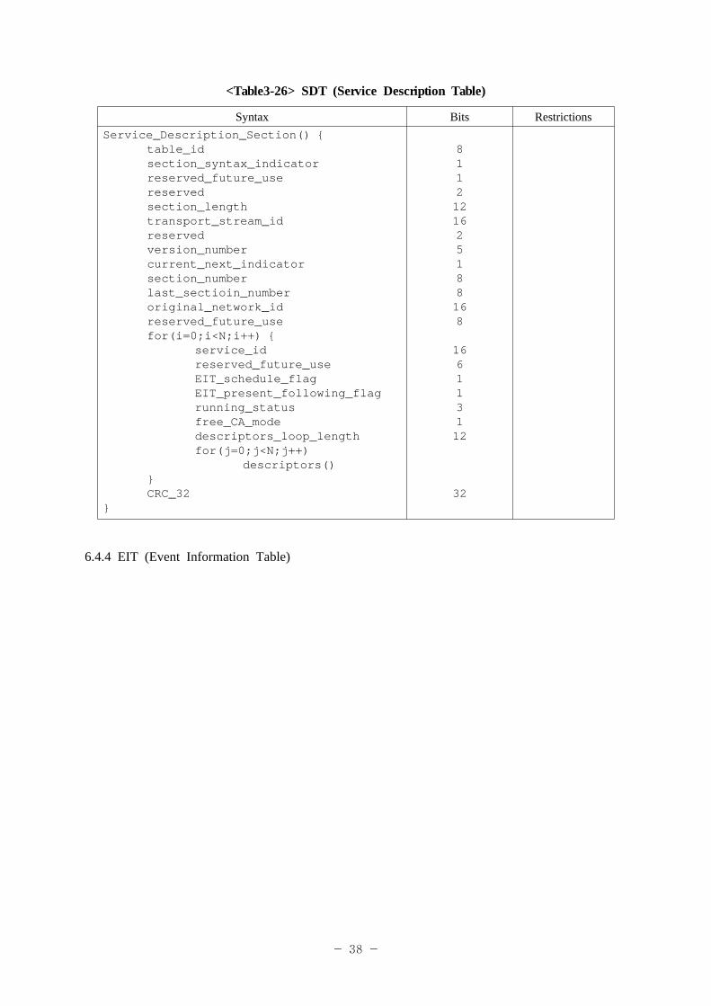
6.4.3 SDT (Service Description Table)
- 38 -
<Table3-26> SDT (Service Description Table)
Syntax Bits RestrictionsService_Description_Section() {
table_idsection_syntax_indicatorreserved_future_usereservedsection_lengthtransport_stream_idreservedversion_numbercurrent_next_indicatorsection_numberlast_sectioin_numberoriginal_network_idreserved_future_usefor(i=0;i<N;i++) {
service_idreserved_future_useEIT_schedule_flagEIT_present_following_flagrunning_statusfree_CA_modedescriptors_loop_lengthfor(j=0;j<N;j++)
descriptors()}CRC_32
}
8112121625188168
166113112
32
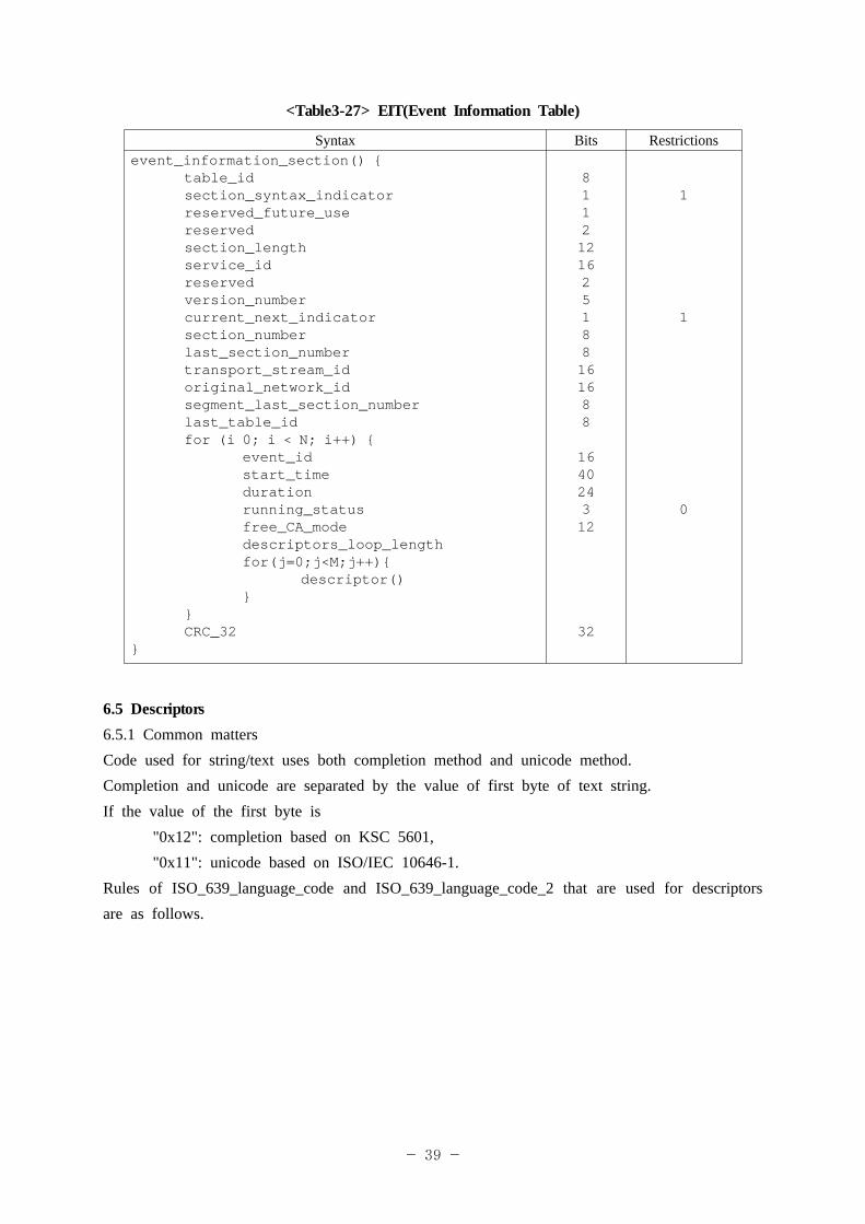
6.4.4 EIT (Event Information Table)
- 39 -
<Table3-27> EIT(Event Information Table)
Syntax Bits Restrictionsevent_information_section() {
table_idsection_syntax_indicatorreserved_future_usereservedsection_lengthservice_idreservedversion_numbercurrent_next_indicatorsection_numberlast_section_numbertransport_stream_idoriginal_network_idsegment_last_section_numberlast_table_idfor (i 0; i < N; i++) {
event_idstart_timedurationrunning_statusfree_CA_modedescriptors_loop_lengthfor(j=0;j<M;j++){
descriptor()}
}CRC_32
}
8112121625188161688
164024312
32
1
1
0
6.5 Descriptors6.5.1 Common mattersCode used for string/text uses both completion method and unicode method.Completion and unicode are separated by the value of first byte of text string.If the value of the first byte is
"0x12": completion based on KSC 5601,"0x11": unicode based on ISO/IEC 10646-1.
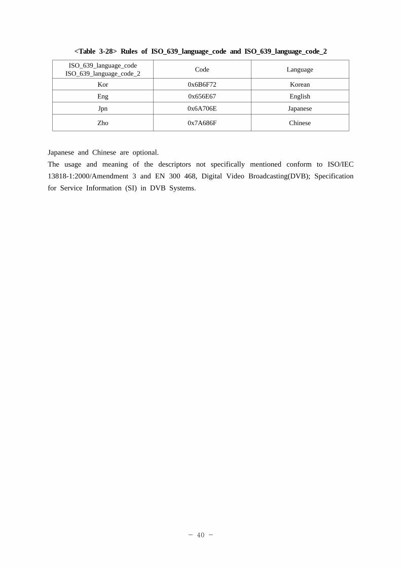
Rules of ISO_639_language_code and ISO_639_language_code_2 that are used for descriptors are as follows.
- 40 -
<Table 3-28> Rules of ISO_639_language_code and ISO_639_language_code_2
ISO_639_language_code ISO_639_language_code_2 Code Language
Kor 0x6B6F72 Korean
Eng 0x656E67 English
Jpn 0x6A706E Japanese
Zho 0x7A686F Chinese
Japanese and Chinese are optional.The usage and meaning of the descriptors not specifically mentioned conform to ISO/IEC 13818-1:2000/Amendment 3 and EN 300 468, Digital Video Broadcasting(DVB); Specification for Service Information (SI) in DVB Systems.
- 41 -
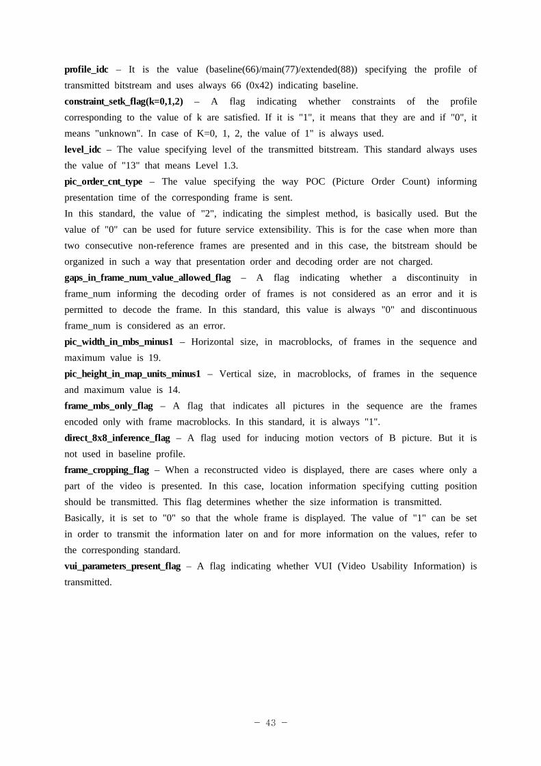
Clause 7. Audio/Video Coding
7.1 Video coding 7.1.1 Video coding follows ITU-T Rec. H.264 | ISO/IEC 14496-10 AVC: Advanced Video Coding for Generic Audio-visual Services.
7.1.2 Compression algorithm of video signal is based on H.264 Baseline Profile Level 1.3 defined in ISO/IEC 14496-10 MPEG-4 Part 10 or Annex A in ITU-T Rec. H.264.
7.1.3 Frame rate is 15 fps at least.
7.1.4 The size of DPB(Decoded Picture Buffer) is set to 3 frames.
7.1.5 The set of coding tools used for the transmitted bitstreams includes all visual tools of baseline profile of ISO/IEC 14496-10 MPEG-4 part 10 or ITU-T Rec. H.264 but the bitstreams should be decodable in baseline profile, main profile, and extended profile decoders. For this, functions of "support for ASO (Arbitrary Slice Order)", "support for one or more num_slice_groups_minus1" and "support for one or more redundant_pic_cnt" are not used.
7.1.6 In order to prevent Random access and error propagation, IDR (Instantaneous Decoding Refresh) picture is transmitted within minimum 500 msec and maximum 2 seconds. And, all Access Units including IDR include SPS and PPS so as to become Random Access Point.
7.1.7 The number of parameter set with other identifiers (id) is limited to maximum 4 in SPS (Sequence Parameter Set) and maximum 8 in PPS (Picture Parameter Set).
7.1.8 The size of vbv_buffer is set to maximum 3.0 seconds and minimum 0.5 seconds.
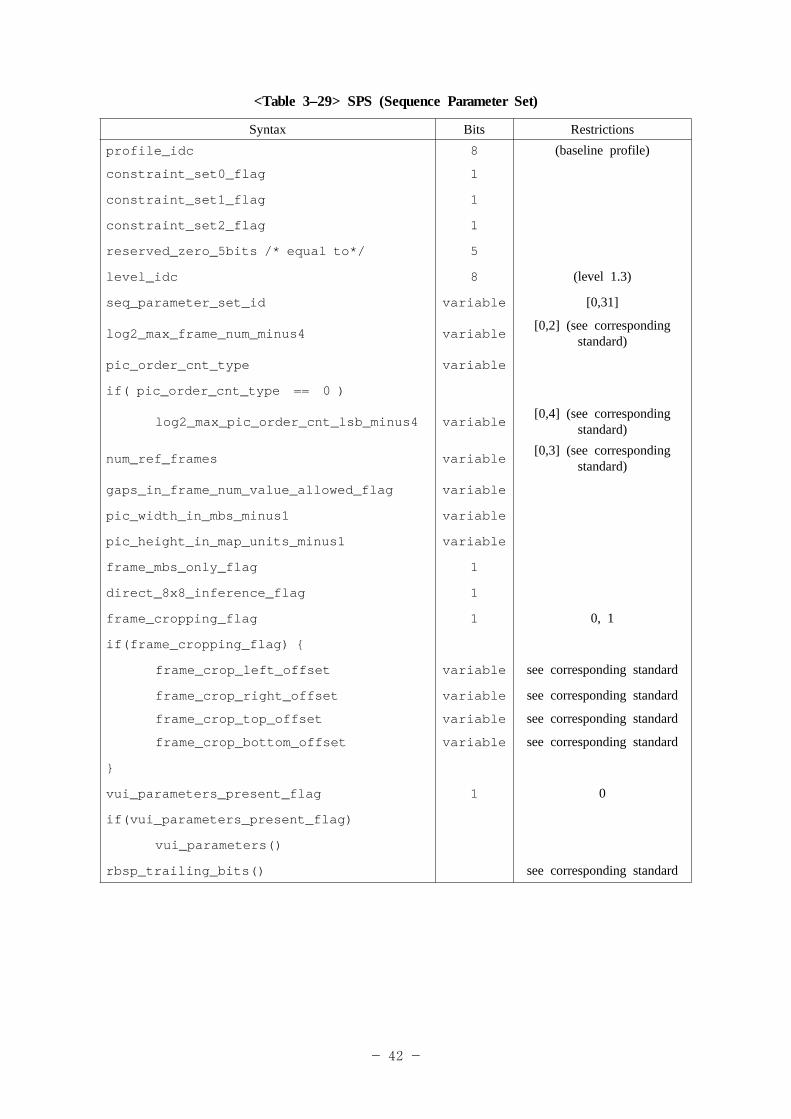
7.1.9 Syntax information of SPS/PPS/slice_header is as follows. Shaded parts means the value is fixed and "corresponding standard" means ISO/IEC 14496-10 MPEG-4 part 10 or ITU-T Rec. H.264.
- 42 -
<Table 3–29> SPS (Sequence Parameter Set)
Syntax Bits Restrictionsprofile_idc 8 (baseline profile)
constraint_set0_flag 1
constraint_set1_flag 1
constraint_set2_flag 1
reserved_zero_5bits /* equal to*/ 5
level_idc 8 (level 1.3)
seq_parameter_set_id variable [0,31]
log2_max_frame_num_minus4 variable[0,2] (see corresponding
standard)
pic_order_cnt_type variable
if( pic_order_cnt_type == 0 )
log2_max_pic_order_cnt_lsb_minus4 variable[0,4] (see corresponding
standard)
num_ref_frames variable[0,3] (see corresponding
standard)
gaps_in_frame_num_value_allowed_flag variable
pic_width_in_mbs_minus1 variable
pic_height_in_map_units_minus1 variable
frame_mbs_only_flag 1
direct_8x8_inference_flag 1
frame_cropping_flag 1 0, 1
if(frame_cropping_flag) {
frame_crop_left_offset variable see corresponding standard
frame_crop_right_offset variable see corresponding standard
frame_crop_top_offset variable see corresponding standard
frame_crop_bottom_offset variable see corresponding standard
}
vui_parameters_present_flag 1 0
if(vui_parameters_present_flag)
vui_parameters()
rbsp_trailing_bits() see corresponding standard
- 43 -
profile_idc – It is the value (baseline(66)/main(77)/extended(88)) specifying the profile of transmitted bitstream and uses always 66 (0x42) indicating baseline.constraint_setk_flag(k=0,1,2) – A flag indicating whether constraints of the profile corresponding to the value of k are satisfied. If it is "1", it means that they are and if "0", it means "unknown". In case of K=0, 1, 2, the value of 1" is always used.level_idc – The value specifying level of the transmitted bitstream. This standard always uses the value of "13" that means Level 1.3.pic_order_cnt_type – The value specifying the way POC (Picture Order Count) informing presentation time of the corresponding frame is sent.In this standard, the value of "2", indicating the simplest method, is basically used. But the value of "0" can be used for future service extensibility. This is for the case when more than two consecutive non-reference frames are presented and in this case, the bitstream should be organized in such a way that presentation order and decoding order are not charged.gaps_in_frame_num_value_allowed_flag – A flag indicating whether a discontinuity in frame_num informing the decoding order of frames is not considered as an error and it is permitted to decode the frame. In this standard, this value is always "0" and discontinuous frame_num is considered as an error.pic_width_in_mbs_minus1 – Horizontal size, in macroblocks, of frames in the sequence and maximum value is 19.pic_height_in_map_units_minus1 – Vertical size, in macroblocks, of frames in the sequence and maximum value is 14.frame_mbs_only_flag – A flag that indicates all pictures in the sequence are the frames encoded only with frame macroblocks. In this standard, it is always "1".direct_8x8_inference_flag – A flag used for inducing motion vectors of B picture. But it is not used in baseline profile.frame_cropping_flag – When a reconstructed video is displayed, there are cases where only a part of the video is presented. In this case, location information specifying cutting position should be transmitted. This flag determines whether the size information is transmitted.Basically, it is set to "0" so that the whole frame is displayed. The value of "1" can be set in order to transmit the information later on and for more information on the values, refer to the corresponding standard.vui_parameters_present_flag – A flag indicating whether VUI (Video Usability Information) is transmitted.
- 44 -
<Table 3–30> PPS (Picture Parameter Set)
Syntax Bits Restrictions
pic_parameter_set_id variable [0,255]
seq_parameter_set_id variable [0,31]
entropy_coding_mode_flag 1
pic_order_present_flag 1
num_slice_groups_minus1 1
num_ref_idx_l0_active_minus1 variable [0,2]
num_ref_idx_l1_active_minus1 variable [0,2]
weighted_pred_flag 1
weighted_bipred_idc 2 [0,2]
pic_init_qp_minus26 /* relative to 26 */ variable [-26,25]
pic_init_qs_minus26 /* relative to 26 */ variable [-26,25]
chroma_qp_index_offset variable [-12,12]
deblocking_filter_control_present_flag 1 0,1
constrained_intra_pred_flag 1 0,1
redundant_pic_cnt_present_flag 1
rbsp_trailing_bits()see the corresponding
standard
- 45 -
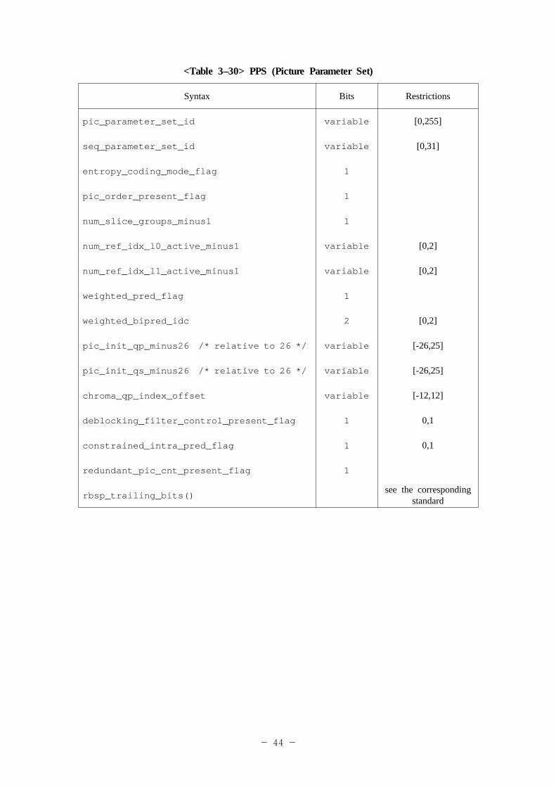
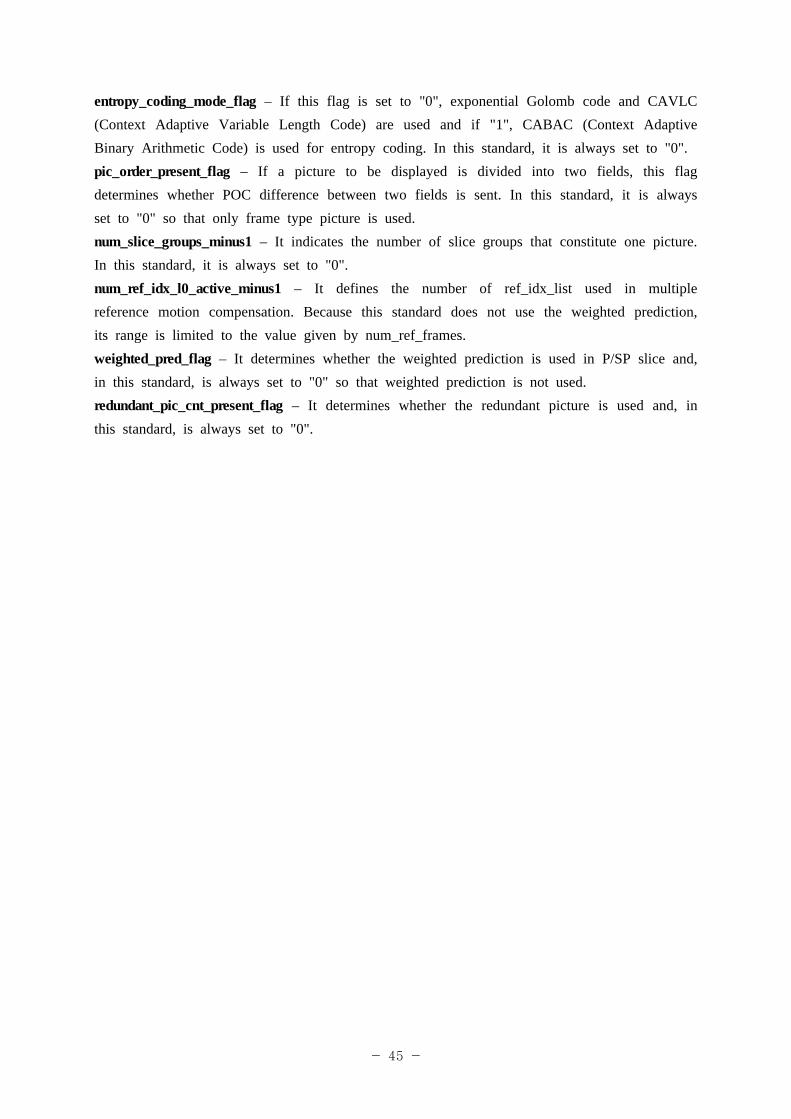
entropy_coding_mode_flag – If this flag is set to "0", exponential Golomb code and CAVLC (Context Adaptive Variable Length Code) are used and if "1", CABAC (Context Adaptive Binary Arithmetic Code) is used for entropy coding. In this standard, it is always set to "0".pic_order_present_flag – If a picture to be displayed is divided into two fields, this flag determines whether POC difference between two fields is sent. In this standard, it is always set to "0" so that only frame type picture is used. num_slice_groups_minus1 – It indicates the number of slice groups that constitute one picture. In this standard, it is always set to "0".num_ref_idx_l0_active_minus1 – It defines the number of ref_idx_list used in multiple reference motion compensation. Because this standard does not use the weighted prediction, its range is limited to the value given by num_ref_frames.weighted_pred_flag – It determines whether the weighted prediction is used in P/SP slice and, in this standard, is always set to "0" so that weighted prediction is not used.redundant_pic_cnt_present_flag – It determines whether the redundant picture is used and, in this standard, is always set to "0".
- 46 -
<Table 3–31> Slice header
Syntax Bits Restrictions
first_mb_in_slice variablesee the corresponding
standard
slice_type variable 0,2,5,7
pic_parameter_set_id variable [0,255]
frame_num variablesee the corresponding
standard
if( nal_unit_type == 5 )
idr_pic_id variable [0,65535]
if( pic_order_cnt_type == 0 ) {
pic_order_cnt_lsb variablesee the corresponding
standard
}
if( slice_type == P) {
num_ref_idx_active_override_flag 1 0,1
if( num_ref_idx_active_override_flag ) {
num_ref_idx_l0_active_minus1 variable [0,3]
}
}
ref_pic_list_reordering()see the corresponding
standardif( nal_ref_idc != 0 )
dec_ref_pic_marking()see the corresponding
standard
slice_qp_delta variablesee the corresponding
standard
if( deblocking_filter_control_present_flag ) {
disable_deblocking_filter_idc variable [0,2]
if( disable_deblocking_filter_idc != 1 ) {
slice_alpha_c0_offset_div2 variable [-6,6]
slice_beta_offset_div2 variable [-6,6]
}
}
- 47 -
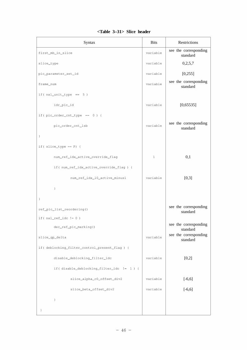
first_mb_in_slice – It indicates the first macroblock number of the slice. In case of an intra frame, because it is limited to be organized in one NALU (slice), it is always set to "0".slice_type – It is the coding type of the slice and indicates one coding type out of I/P/B/SI/SP.ref_pic_list_reordering( ) – It is the information used for rearranging basic reference pictures list in P frame coding.dec_ref_pic_marking( ) – It is the information used in a special arrangement for effective coding instead of arranging reference pictures in P frame coding.
7.2 Audio coding7.2.1 General mattersA. Profile
AAC LC profile defined in "ISO/IEC 13818-7"is applied. Specification for SBR follows 14496-3 AMD1.
B. Sampling frequency itemsOne value is used among 0x3 (48KHz), 0x5 (32KHz) and 0x6 (24KHz), and the value shall not be changed during a program.
C. ChannelIt supports mono and stereo. The number of channel shall not be changed during a program.
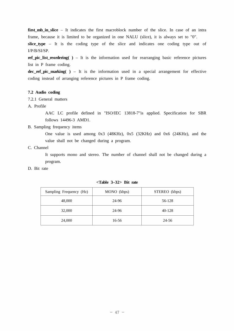
D. Bit rate
<Table 3–32> Bit rate
Sampling Frequency (Hz) MONO (kbps) STEREO (kbps)
48,000 24-96 56-128
32,000 24-96 40-128
24,000 16-56 24-56
- 48 -
E. BitstreamIt follows ADTS (Audio Data Transport Stream) format defined in "ISO/IEC 13818-7".
F. SBR signalingUsing SBR_flag in AAC_descriptor() defined in subclause 1.8, signaling is performed in order to determine whether it is AAC or AAC+SBR.
G. SBR headerThe SBR header is inserted at least at every two seconds to prevent errror propagation.
7.2.2 DetailsA. Bitstream format
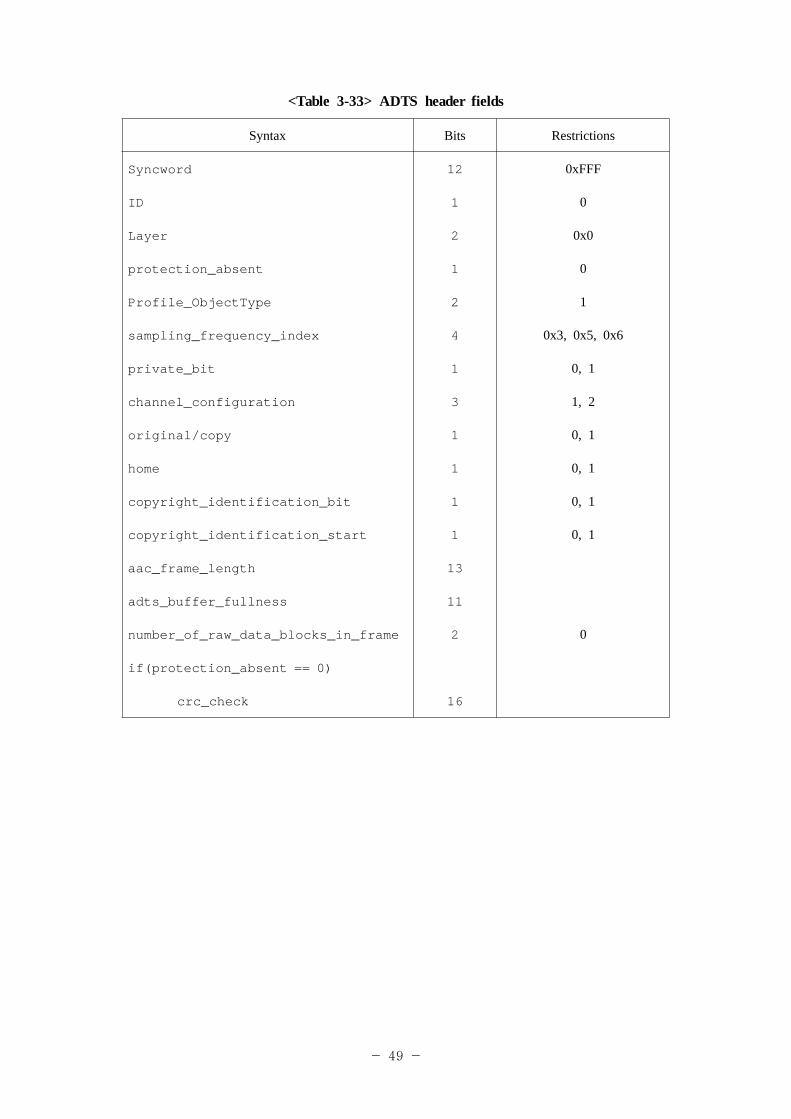
A bitstream is transmitted in ADTS format. One ADTS frame is composed of ADTS header and audio data. Audio data follows the format of raw_data_block() defined in "ISO/IEC 13818-7" and "ISO/IEC 14496-3:2001/Amd. 1:2003".
- 49 -
<Table 3-33> ADTS header fields
Syntax Bits Restrictions
Syncword 12 0xFFF
ID 1 0
Layer 2 0x0
protection_absent 1 0
Profile_ObjectType 2 1
sampling_frequency_index 4 0x3, 0x5, 0x6
private_bit 1 0, 1
channel_configuration 3 1, 2
original/copy 1 0, 1
home 1 0, 1
copyright_identification_bit 1 0, 1
copyright_identification_start 1 0, 1
aac_frame_length 13
adts_buffer_fullness 11
number_of_raw_data_blocks_in_frame 2 0
if(protection_absent == 0)
crc_check 16
- 50 -
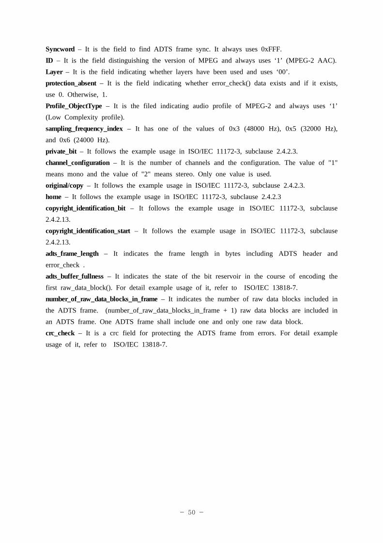
Syncword – It is the field to find ADTS frame sync. It always uses 0xFFF.ID – It is the field distinguishing the version of MPEG and always uses ‘1’ (MPEG-2 AAC).Layer – It is the field indicating whether layers have been used and uses ‘00’.protection_absent – It is the field indicating whether error_check() data exists and if it exists, use 0. Otherwise, 1.Profile_ObjectType – It is the filed indicating audio profile of MPEG-2 and always uses ‘1’ (Low Complexity profile). sampling_frequency_index – It has one of the values of 0x3 (48000 Hz), 0x5 (32000 Hz), and 0x6 (24000 Hz). private_bit – It follows the example usage in ISO/IEC 11172-3, subclause 2.4.2.3.channel_configuration – It is the number of channels and the configuration. The value of "1" means mono and the value of "2" means stereo. Only one value is used.original/copy – It follows the example usage in ISO/IEC 11172-3, subclause 2.4.2.3.home – It follows the example usage in ISO/IEC 11172-3, subclause 2.4.2.3copyright_identification_bit – It follows the example usage in ISO/IEC 11172-3, subclause 2.4.2.13. copyright_identification_start – It follows the example usage in ISO/IEC 11172-3, subclause 2.4.2.13.adts_frame_length – It indicates the frame length in bytes including ADTS header and error_check .adts_buffer_fullness – It indicates the state of the bit reservoir in the course of encoding the first raw_data_block(). For detail example usage of it, refer to ISO/IEC 13818-7. number_of_raw_data_blocks_in_frame – It indicates the number of raw data blocks included in the ADTS frame. (number_of_raw_data_blocks_in_frame + 1) raw data blocks are included in an ADTS frame. One ADTS frame shall include one and only one raw data block.crc_check – It is a crc field for protecting the ADTS frame from errors. For detail example usage of it, refer to ISO/IEC 13818-7.
- 51 -
Clause 8. CDM modulation section
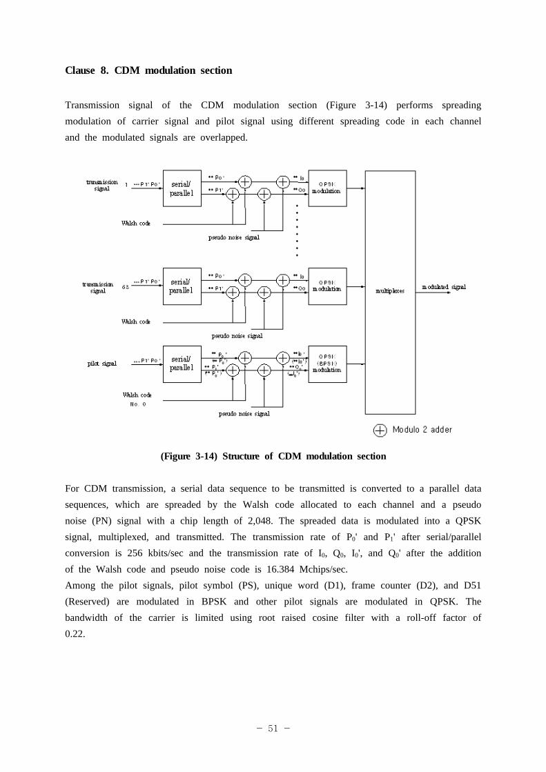
Transmission signal of the CDM modulation section (Figure 3-14) performs spreading modulation of carrier signal and pilot signal using different spreading code in each channel and the modulated signals are overlapped.
(Figure 3-14) Structure of CDM modulation section
For CDM transmission, a serial data sequence to be transmitted is converted to a parallel data sequences, which are spreaded by the Walsh code allocated to each channel and a pseudo noise (PN) signal with a chip length of 2,048. The spreaded data is modulated into a QPSK signal, multiplexed, and transmitted. The transmission rate of P0' and P1' after serial/parallel conversion is 256 kbits/sec and the transmission rate of I0, Q0, I0', and Q0' after the addition of the Walsh code and pseudo noise code is 16.384 Mchips/sec.Among the pilot signals, pilot symbol (PS), unique word (D1), frame counter (D2), and D51 (Reserved) are modulated in BPSK and other pilot signals are modulated in QPSK. The bandwidth of the carrier is limited using root raised cosine filter with a roll-off factor of 0.22.
- 52 -
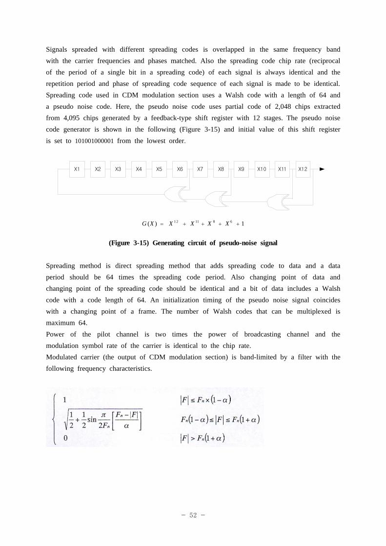
Signals spreaded with different spreading codes is overlapped in the same frequency band with the carrier frequencies and phases matched. Also the spreading code chip rate (reciprocal of the period of a single bit in a spreading code) of each signal is always identical and the repetition period and phase of spreading code sequence of each signal is made to be identical. Spreading code used in CDM modulation section uses a Walsh code with a length of 64 and a pseudo noise code. Here, the pseudo noise code uses partial code of 2,048 chips extracted from 4,095 chips generated by a feedback-type shift register with 12 stages. The pseudo noise code generator is shown in the following (Figure 3-15) and initial value of this shift register is set to 101001000001 from the lowest order.
X1 X2 X3 X4 X5 X6 X7 X8 X9 X10 X11 X12
1)( 68111 2 ++++= XXXXXG
(Figure 3-15) Generating circuit of pseudo-noise signal
Spreading method is direct spreading method that adds spreading code to data and a data period should be 64 times the spreading code period. Also changing point of data and changing point of the spreading code should be identical and a bit of data includes a Walsh code with a code length of 64. An initialization timing of the pseudo noise signal coincides with a changing point of a frame. The number of Walsh codes that can be multiplexed is maximum 64. Power of the pilot channel is two times the power of broadcasting channel and the modulation symbol rate of the carrier is identical to the chip rate.Modulated carrier (the output of CDM modulation section) is band-limited by a filter with the following frequency characteristics.
- 53 -
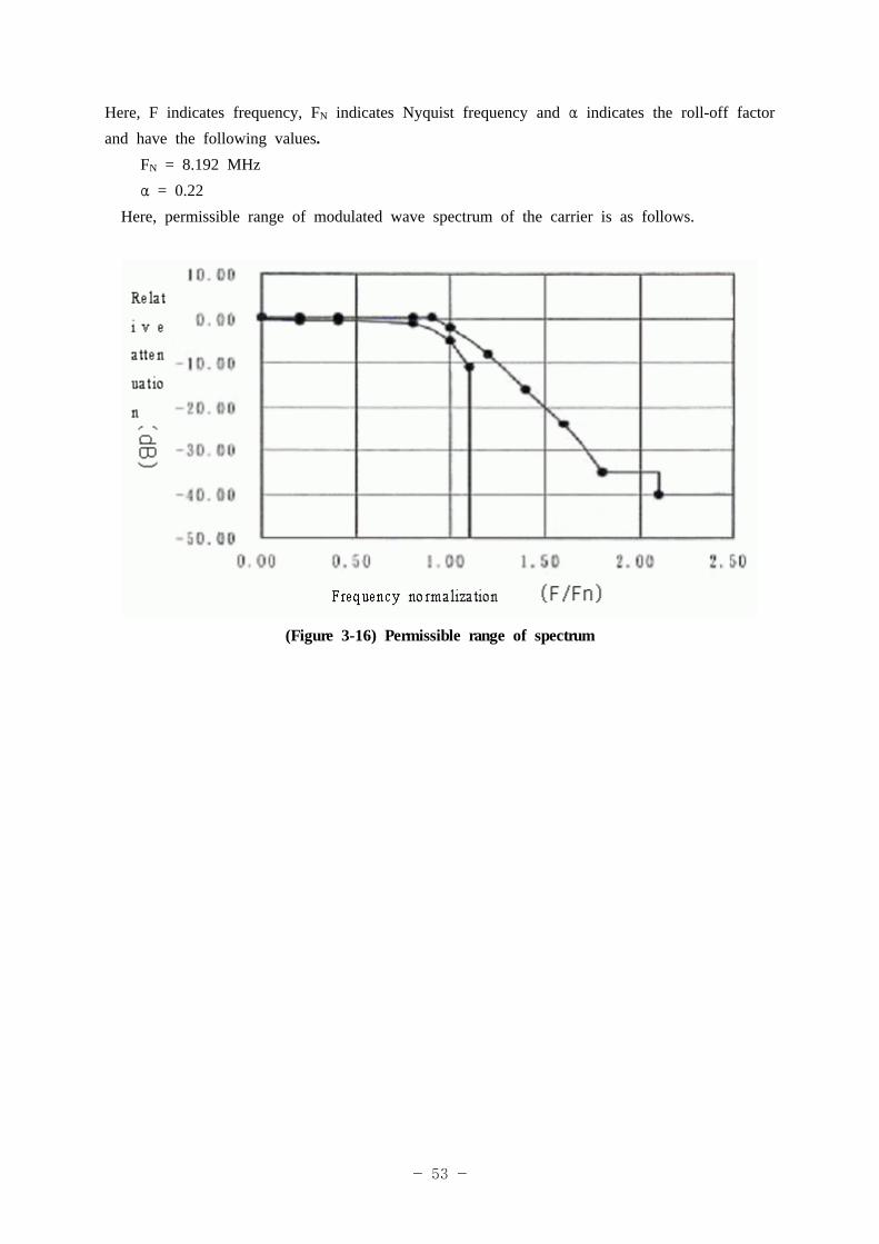
Here, F indicates frequency, FN indicates Nyquist frequency and α indicates the roll-off factor and have the following values.
FN = 8.192 MHzα = 0.22
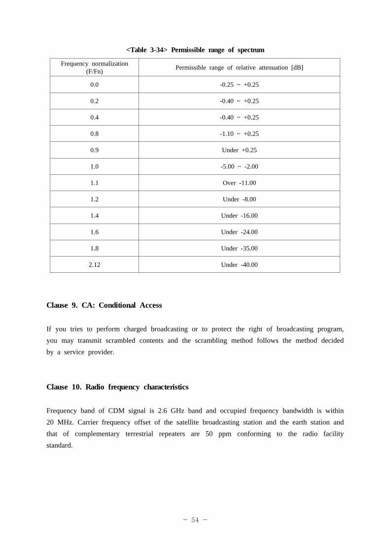
Here, permissible range of modulated wave spectrum of the carrier is as follows.
(Figure 3-16) Permissible range of spectrum
- 54 -
<Table 3-34> Permissible range of spectrum
Frequency normalization (F/Fn) Permissible range of relative attenuation [dB]
0.0 -0.25 ~ +0.25
0.2 -0.40 ~ +0.25
0.4 -0.40 ~ +0.25
0.8 -1.10 ~ +0.25
0.9 Under +0.25
1.0 -5.00 ~ -2.00
1.1 Over -11.00
1.2 Under -8.00
1.4 Under -16.00
1.6 Under -24.00
1.8 Under -35.00
2.12 Under -40.00
Clause 9. CA: Conditional Access
If you tries to perform charged broadcasting or to protect the right of broadcasting program, you may transmit scrambled contents and the scrambling method follows the method decided by a service provider.
Clause 10. Radio frequency characteristics
Frequency band of CDM signal is 2.6 GHz band and occupied frequency bandwidth is within 20 MHz. Carrier frequency offset of the satellite broadcasting station and the earth station and that of complementary terrestrial repeaters are 50 ppm conforming to the radio facility standard.
- 55 -
Clause 11. Bit Error Rate(BER) performance
The target value of bit error rate of a receiver shall be under 2*10E-4 after Viterbi decoding according to the standard of ITU-R Rec. BO. 1130-4.
Clause 12. Basic character set in satellite digital multimedia broadcasting
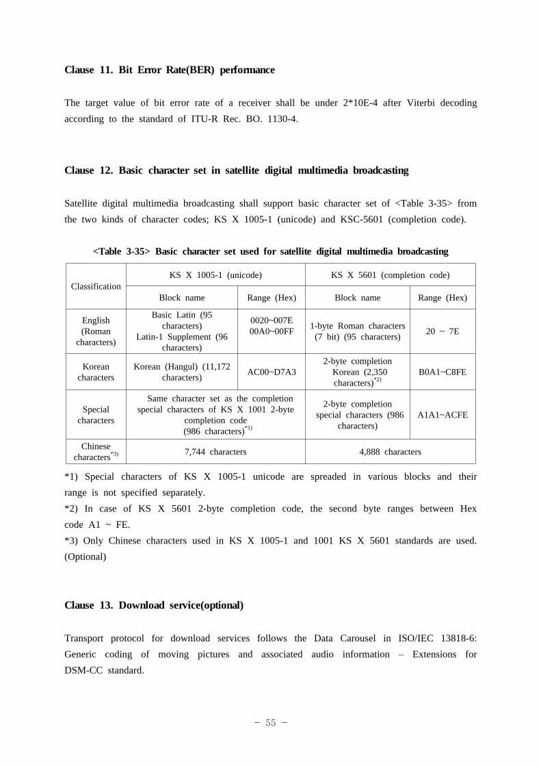
Satellite digital multimedia broadcasting shall support basic character set of <Table 3-35> from the two kinds of character codes; KS X 1005-1 (unicode) and KSC-5601 (completion code).
<Table 3-35> Basic character set used for satellite digital multimedia broadcasting
ClassificationKS X 1005-1 (unicode) KS X 5601 (completion code)
Block name Range (Hex) Block name Range (Hex)
English(Roman
characters)
Basic Latin (95 characters)
Latin-1 Supplement (96 characters)
0020~007E00A0~00FF 1-byte Roman characters
(7 bit) (95 characters) 20 ~ 7E
Korean characters
Korean (Hangul) (11,172 characters) AC00~D7A3
2-byte completion Korean (2,350
characters)*2)B0A1~C8FE
Special characters
Same character set as the completion special characters of KS X 1001 2-byte
completion code (986 characters)*1)
2-byte completion special characters (986
characters)A1A1~ACFE
Chinese characters*3) 7,744 characters 4,888 characters
*1) Special characters of KS X 1005-1 unicode are spreaded in various blocks and their range is not specified separately.*2) In case of KS X 5601 2-byte completion code, the second byte ranges between Hex code A1 ~ FE. *3) Only Chinese characters used in KS X 1005-1 and 1001 KS X 5601 standards are used. (Optional)
Clause 13. Download service(optional)
Transport protocol for download services follows the Data Carousel in ISO/IEC 13818-6: Generic coding of moving pictures and associated audio information – Extensions for DSM-CC standard.
- 56 -
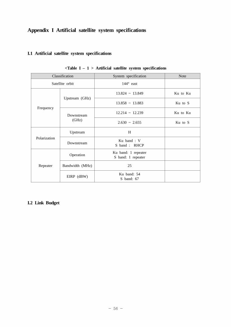
Appendix I Artificial satellite system specifications
I.1 Artificial satellite system specifications
<Table I – 1 > Artificial satellite system specifications
Classification System specification Note
Satellite orbit 144° east
Frequency
Upstream (GHz)13.824 ~ 13.849 Ku to Ku
13.858 ~ 13.883 Ku to S
Downstream (GHz)
12.214 ~ 12.239 Ku to Ku
2.630 ~ 2.655 Ku to S
PolarizationUpstream H
Downstream Ku band : V S band : RHCP
Repeater
Operation Ku band: 1 repeaterS band: 1 repeater
Bandwidth (MHz) 25
EIRP (dBW) Ku band: 54S band: 67
I.2 Link Budget
- 57 -
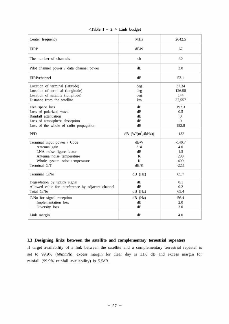
<Table I – 2 > Link budget
Center frequency MHz 2642.5
EIRP dBW 67
The number of channels ch 30
Pilot channel power / data channel power dB 3.0
EIRP/channel dB 52.1
Location of terminal (latitude)Location of terminal (longitude)Location of satellite (longitude)Distance from the satellite
degdegdegkm
37.34126.58
14437,557
Free space lossLoss of polarized waveRainfall attenuationLoss of atmosphere absorption Loss of the whole of radio propagation
dBdBdBdBdB
192.30.500
192.8
PFD dB (W/(m2,4kHz)) -132
Terminal input power / CodeAntenna gainLNA noise figure factorAntenna noise temperatureWhole system noise temperature
Terminal G/T
dBWdBidBKK
dB/K
-140.74.01.5290409
-22.1
Terminal C/No dB (Hz) 65.7
Degradation by uplink signalAllowed value for interference by adjacent channel Total C/No
dBdB
dB (Hz)
0.10.2
65.4
C/No for signal receptionImplementation lossDiversity loss
dB (Hz)dBdB
56.42.03.0
Link margin dB 4.0
I.3 Designing links between the satellite and complementary terrestrial repeaters If target availability of a link between the satellite and a complementary terrestrial repeater is set to 99.9% (60mm/h), excess margin for clear day is 11.8 dB and excess margin for rainfall (99.9% rainfall availability) is 5.5dB.
- 58 -
Appendix II General features of complementary terrestrial repeater
II.1 Frequency plan
<Table II – 1> Plan of complementary terrestrial repeater frequency
Classification Satellite receive link Terrestrial transmitting linkFrequency band 12.214 ~ 12.239 GHz 2630 ~ 2655 MHz
Bandwidth 25 MHz 25 MHz
Polarization Circular polarization Linear polarization
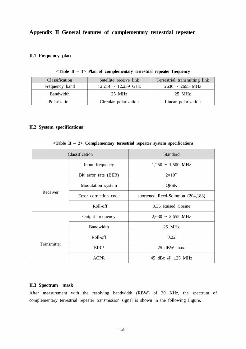
II.2 System specifications
<Table II – 2> Complementary terrestrial repeater system specifications
Classification Standard
Receiver
Input frequency 1,250 ~ 1,500 MHz
Bit error rate (BER) 2×10⁻⁴
Modulation system QPSK
Error correction code shortened Reed-Solomon (204,188)
Roll-off 0.35 Raised Cosine
Transmitter
Output frequency 2,630 ~ 2,655 MHz
Bandwidth 25 MHz
Roll-off 0.22
EIRP 25 dBW max.
ACPR 45 dBc @ ±25 MHz
II.3 Spectrum maskAfter measurement with the resolving bandwidth (RBW) of 30 KHz, the spectrum of complementary terrestrial repeater transmission signal is shown in the following Figure.
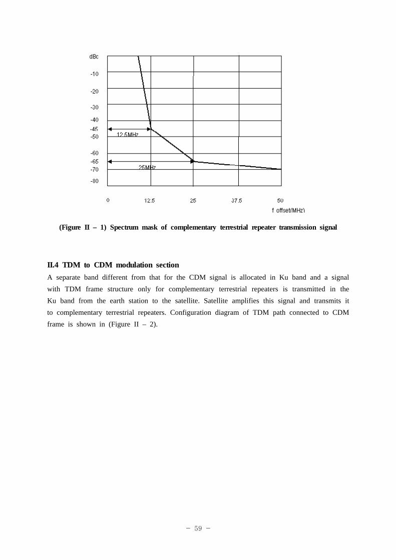
- 59 -
(Figure II – 1) Spectrum mask of complementary terrestrial repeater transmission signal
II.4 TDM to CDM modulation sectionA separate band different from that for the CDM signal is allocated in Ku band and a signal with TDM frame structure only for complementary terrestrial repeaters is transmitted in the Ku band from the earth station to the satellite. Satellite amplifies this signal and transmits it to complementary terrestrial repeaters. Configuration diagram of TDM path connected to CDM frame is shown in (Figure II – 2).
- 60 -
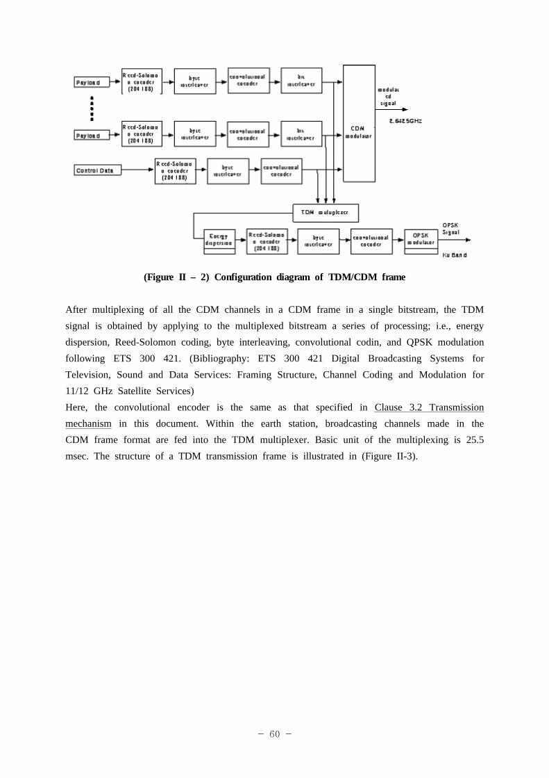
(Figure II – 2) Configuration diagram of TDM/CDM frame
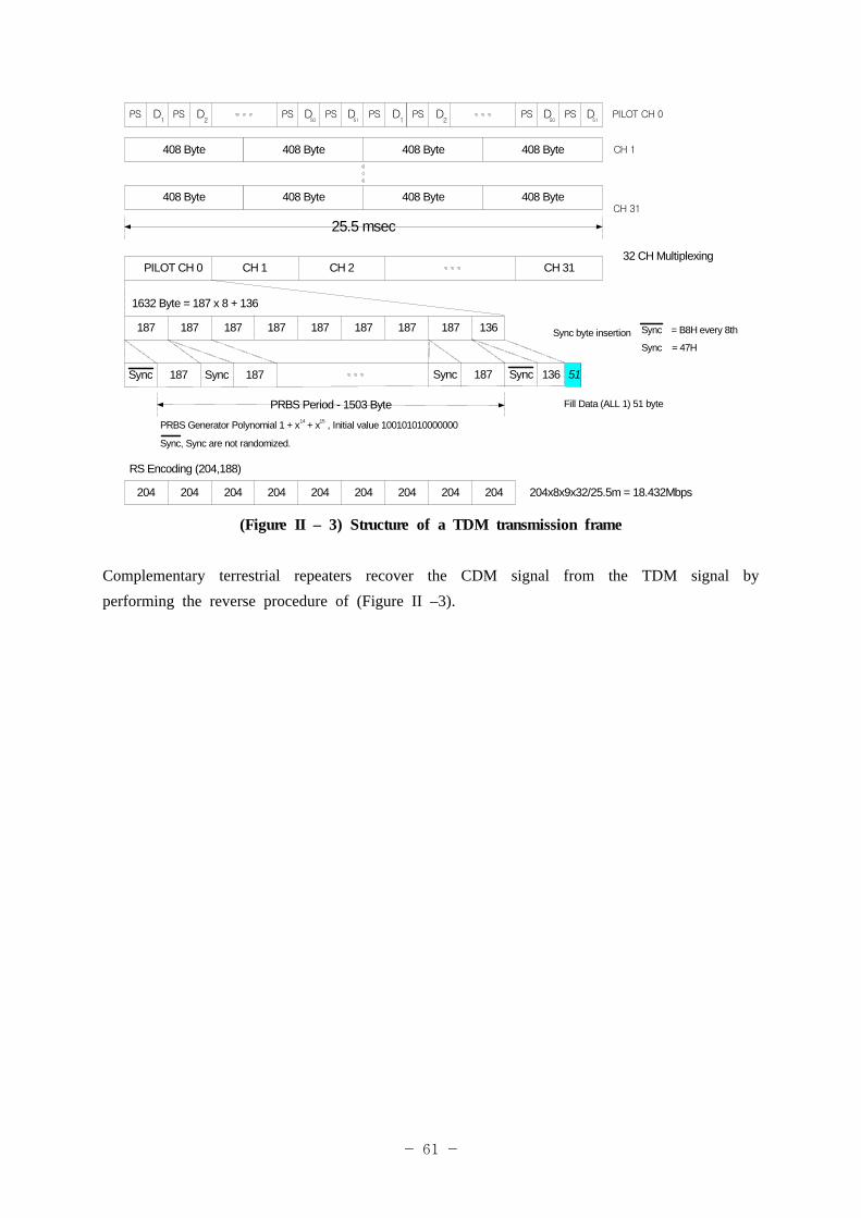
After multiplexing of all the CDM channels in a CDM frame in a single bitstream, the TDM signal is obtained by applying to the multiplexed bitstream a series of processing; i.e., energy dispersion, Reed-Solomon coding, byte interleaving, convolutional codin, and QPSK modulation following ETS 300 421. (Bibliography: ETS 300 421 Digital Broadcasting Systems for Television, Sound and Data Services: Framing Structure, Channel Coding and Modulation for 11/12 GHz Satellite Services)Here, the convolutional encoder is the same as that specified in Clause 3.2 Transmission mechanism in this document. Within the earth station, broadcasting channels made in the CDM frame format are fed into the TDM multiplexer. Basic unit of the multiplexing is 25.5 msec. The structure of a TDM transmission frame is illustrated in (Figure II-3).
- 61 -
PILOT CH 0PSPS D1 2
D
CH 1
PSPS50
D51
D PSPS D1 2
D PSPS50
D51
D
408 Byte 408 Byte408 Byte408 Byte
408 Byte 408 Byte408 Byte408 ByteCH 31
32 CH Multiplexing
25.5 msec
1632 Byte = 187 x 8 + 136
Sync byte insertion
Fill Data (ALL 1) 51 byte
Sync
Sync
= B8H every 8th
= 47H
PILOT CH 0 CH 1 CH 31CH 2
204x8x9x32/25.5m = 18.432Mbps
RS Encoding (204,188)
187 187 187187187187187 187 136
187 187SyncSync
PRBS Period - 1503 Byte
PRBS Generator Polynomial 1 + x + x , Initial value 10010101000000014 15
204 204 204204204204204 204 204
Sync 136 51187 Sync
Sync, Sync are not randomized.
(Figure II – 3) Structure of a TDM transmission frame
Complementary terrestrial repeaters recover the CDM signal from the TDM signal by performing the reverse procedure of (Figure II –3).
- 62 -
Appendix III Guideline on download transmission and receipt
III.1 Application of download
III.1.1 Modification of receiver software Receiver software is modified. The modification may include bug corrections, error
corrections according to different interpretations on operations between transmitters and receivers, improvement of display or response speed, and improvement of manipulation. Also it may include modifications to such data common in all receivers as logo data of broadcasters, broadcast program genre code table, broadcast program property code table, reserved word table, and satellite digital multimedia broadcasting extended information.
III.1.2 Update of genre code table and broadcast program property code tableIII.1.2.1 Update for once defined area is not performed and only addition is performed.III.1.2.2 Content description after defining each table is in maximum 20 characters. The same applies to the maximum number of characters in an update data.III.1.2.3 Broadcast program property code is updated when content_nibble_1 starts with 0xE.
III.1.3 Update of reserved word tableIII.1.3.1 Update for once defined area is not performed and only addition is performed.III.1.3.2 The maximum length of reserved word is no more than 8 characters or 16 bytes. The same applies to the update data.III.1.3.3 Reserved word is the item name coded in extended_event_descriptor of SI and coding is not performed.
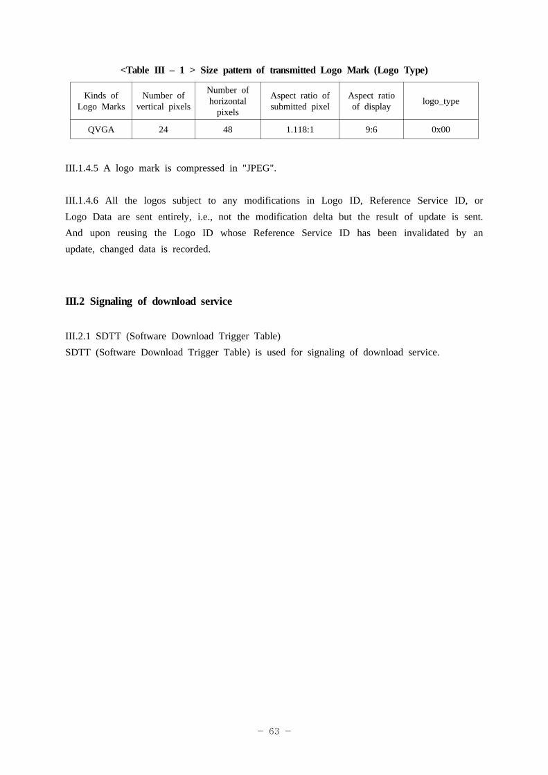
III.1.4 Update of logo dataIII.1.4.1 Logo data can be added and once defined logo data can be modified.III.1.4.2 Considering forseeable number of broadcasters and broadcast program providers and the number of services, the number of services and logo data that should be stored in non-volatile memory of a receiver is limited to 100 and 100 different kinds, respectively.III.1.4.3 Within receivers, a logo data is managed by Logo ID (9 bit).III.1.4.4 Size pattern of logo is shown in <Table III – 1>. It is impossible to transmit logo data for a service that is not present in NIT.
- 63 -
<Table III – 1 > Size pattern of transmitted Logo Mark (Logo Type)
Kinds of Logo Marks
Number of vertical pixels
Number of horizontal
pixels
Aspect ratio of submitted pixel
Aspect ratio of display logo_type
QVGA 24 48 1.118:1 9:6 0x00
III.1.4.5 A logo mark is compressed in "JPEG".
III.1.4.6 All the logos subject to any modifications in Logo ID, Reference Service ID, or Logo Data are sent entirely, i.e., not the modification delta but the result of update is sent. And upon reusing the Logo ID whose Reference Service ID has been invalidated by an update, changed data is recorded.
III.2 Signaling of download service
III.2.1 SDTT (Software Download Trigger Table)SDTT (Software Download Trigger Table) is used for signaling of download service.
- 64 -
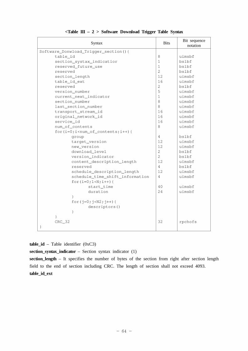
<Table III – 2 > Software Download Trigger Table Syntax
Syntax Bits Bit sequence notation
Software_Donwload_Trigger_section(){table_idsection_systax_indicatiorreserved_future_usereservedsection_lengthtable_id_extreservedversion_numbercurrent_next_indicatorsection_numberlast_section_numbertransport_stream_idoriginal_network_idservice_idnum_of_contentsfor(i=0;i<num_of_contents;i++){
grouptarget_versionnew_versiondownload_levelversion_indicatorcontent_description_lengthreservedschedule_description_lengthschedule_time_shift_informationfor(i=0;1<N;i++){
start_timeduration
}for(j=0;j<N2;j++){
descriptors()}
}CRC_32
}
81121216251881616168
4121222124124
4024
32
uimsbfbslbfbslbfbslbfuimsbfuimsbfbslbfuimsbfuimsbfuimsbfuimsbfuimsbfuimsbfuimsbfuimsbf
bslbfuimsbfuimsbfbslbfbslbfuimsbfbslbfuimsbfuimsbf
uimsbfuimsbf
rpchofs
table_id – Table identifier (0xC3)section_syntax_indicator – Section syntax indicator (1)section_length – It specifies the number of bytes of the section from right after section length field to the end of section including CRC. The length of section shall not exceed 4093.table_id_ext
- 65 -
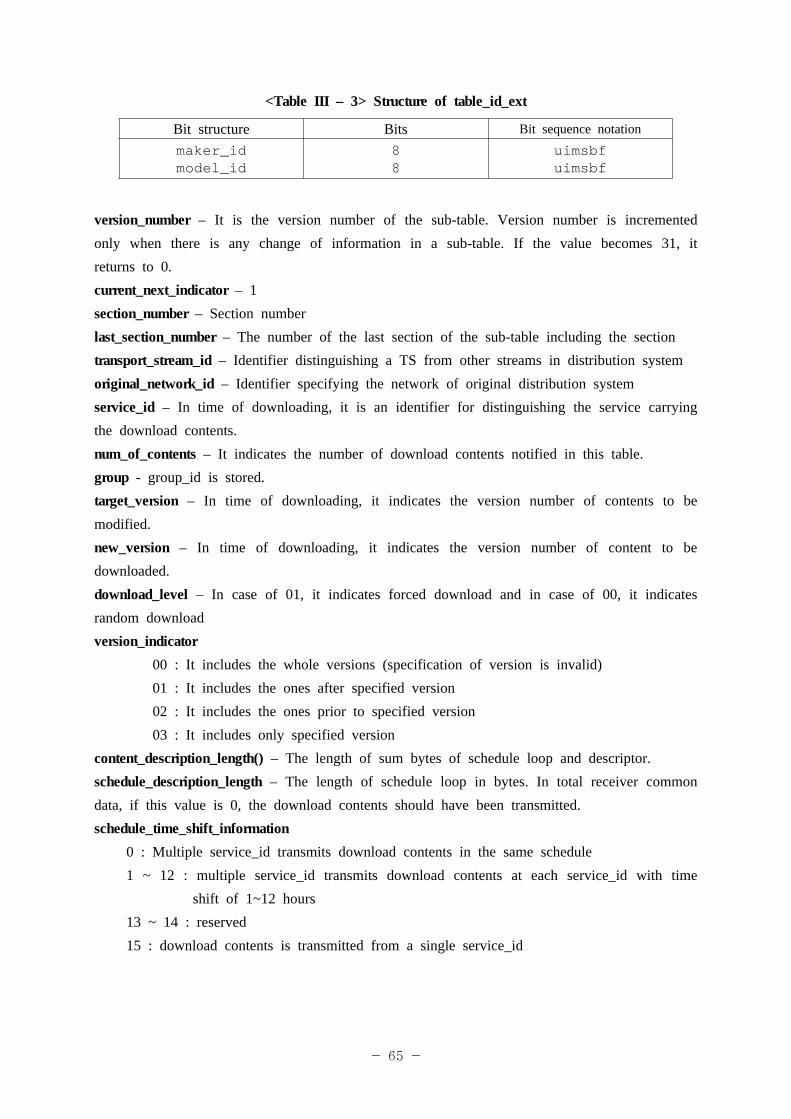
<Table III – 3> Structure of table_id_ext
Bit structure Bits Bit sequence notationmaker_idmodel_id
88
uimsbfuimsbf
version_number – It is the version number of the sub-table. Version number is incremented only when there is any change of information in a sub-table. If the value becomes 31, it returns to 0.current_next_indicator – 1section_number – Section numberlast_section_number – The number of the last section of the sub-table including the sectiontransport_stream_id – Identifier distinguishing a TS from other streams in distribution systemoriginal_network_id – Identifier specifying the network of original distribution systemservice_id – In time of downloading, it is an identifier for distinguishing the service carrying the download contents.num_of_contents – It indicates the number of download contents notified in this table.group - group_id is stored.target_version – In time of downloading, it indicates the version number of contents to be modified.new_version – In time of downloading, it indicates the version number of content to be downloaded.download_level – In case of 01, it indicates forced download and in case of 00, it indicates random downloadversion_indicator 00 : It includes the whole versions (specification of version is invalid) 01 : It includes the ones after specified version 02 : It includes the ones prior to specified version 03 : It includes only specified versioncontent_description_length() – The length of sum bytes of schedule loop and descriptor.schedule_description_length – The length of schedule loop in bytes. In total receiver common data, if this value is 0, the download contents should have been transmitted. schedule_time_shift_information
0 : Multiple service_id transmits download contents in the same schedule1 ~ 12 : multiple service_id transmits download contents at each service_id with time
shift of 1~12 hours13 ~ 14 : reserved15 : download contents is transmitted from a single service_id
- 66 -
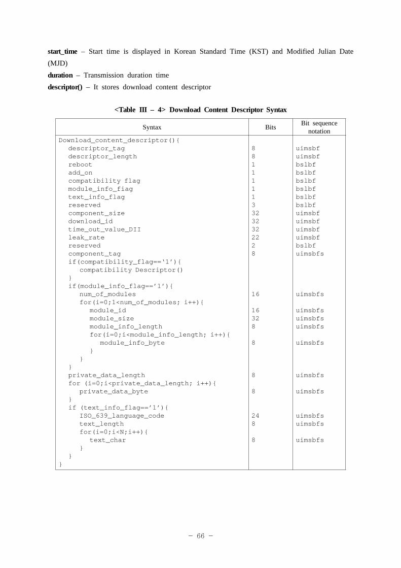
start_time – Start time is displayed in Korean Standard Time (KST) and Modified Julian Date (MJD)duration – Transmission duration timedescriptor() – It stores download content descriptor
<Table III – 4> Download Content Descriptor Syntax
Syntax Bits Bit sequence notation
Download_content_descriptor(){descriptor_tagdescriptor_lengthrebootadd_oncompatibility flagmodule_info_fiagtext_info_flagreservedcomponent_sizedownload_idtime_out_value_DIIleak_ratereservedcomponent_tagif(compatibility_flag==‘1’){
compatibility Descriptor()}if(module_info_flag==’1’){
num_of_modulesfor(i=0;1<num_of_modules; i++){
module_idmodule_sizemodule_info_lengthfor(i=0;i<module_info_length; i++){
module_info_byte}
}}private_data_lengthfor (i=0;i<private_data_length; i++){
private_data_byte}if (text_info_flag==’1’){
ISO_639_language_codetext_lengthfor(i=0;i<N;i++){
text_char}
}}
881111133232322228
16
16328
8
8
8
248
8
uimsbfuimsbfbslbfbslbfbslbfbslbfbslbfbslbfuimsbfuimsbfuimsbfuimsbfbslbfuimsbfs
uimsbfs
uimsbfsuimsbfsuimsbfs
uimsbfs
uimsbfs
uimsbfs
uimsbfsuimsbfs
uimsbfs
- 67 -
descriptor_tag – Identification value indicating the download content descriptor (0xC9)reboot – It describes whether receivers are rebooted in time of terminating download. If the value is 1, receivers are rebooted and if 0, receivers keep working.add_on – It determines whether update for existing module or addition is required. If the value is 1, it indicates addition and if 0, it indicates update.compatibility_fiag – It determines whether CompatibilityDescriptor() among descriptors exists or not. If this flag has the value of 1, the information is coded at every modules and if 0, it is not.text_info_flag – Flag indicating whether service is described at the end of the descriptor. If this flag has the value of 1, service description is coded and if 0, service description is not coded.component_size – Sum of transmission data size in the carousel (unit : bytes)download_id – Download identifier specified for identifying registration number of download. Download identifier specified here is specified in DII/DDB in time of actual delivery.time_out_value_DII – Timeout value recommended for receipt of the whole section of DII of the carousel (unit : msec)leak_rate – Leakage rate of transport buffer of receivers (unit : 50 bytes/s)component_tag – It is matched with stream_identifier_descriptor of PMT. Component tag value of the corresponding stream is included.compatibilityDescriptor() – It includes the exactly same thing as CompatibilityDescriptor in DII. In SDTT, the rule of contents to be downloaded that cannot be specified in table_id_ext/group is specified here.number_of_modules – It indicates the number of modules.module_id – Module identifier used for file transfer in downloadingmodule_size – The length of the module in bytes. The value of zero means unspecified length.module_info_length – It indicates the length of module_info_byte in bytes.module_info_byte – It stores necessary descriptor among type descriptor, name descriptor,info descriptor, and control descriptor described in DII.ISO_639_language_code – It identifies the language of string used for describing services.text_length – The length of service string (unit: bytes)text_char – String on service of download contents being transmitted.
- 68 -
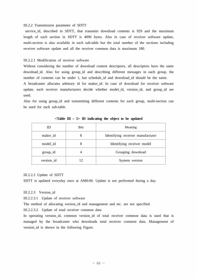
III.2.2 Transmission parameter of SDTT service_id, described in SDTT, that transmits download contents is 929 and the maximum length of each section in SDTT is 4096 bytes. Also in case of receiver software update, multi-section is also available in each sub-table but the total number of the sections including receiver software update and all the receiver common data is maximum 180.
III.2.2.1 Modification of receiver softwareWithout considering the number of download content descriptors, all descriptors have the same download_id. Also for using group_id and describing different messages in each group, the number of contents can be under 1, but schedule_id and download_id should be the same.A broadcaster allocates arbitrary id for maker_id. In case of download for receiver software update, each receiver manufacturers decide whether model_id, version_id, and group_id are used.Also for using group_id and transmitting different contents for each group, multi-section can be used for each sub-table.
<Table III – 5> ID indicating the object to be updated
ID Bits Meaning
maker_id 8 Identifying receiver manufacturer
model_id 8 Identifying receiver model
group_id 4 Grouping download
version_id 12 System version
III.2.2.2 Update of SDTTSDTT is updated everyday once at AM0:00. Update is not performed during a day.
III.2.2.3 Version_id III.2.2.3.1 Update of receiver softwareThe method of allocating version_id and management and etc. are not specified.III.2.2.3.2 Update of total receiver common dataIn operating version_id, common version_id of total receiver common data is used that is managed by the broadcaster who downloads total receiver common data. Management of version_id is shown in the following Figure.
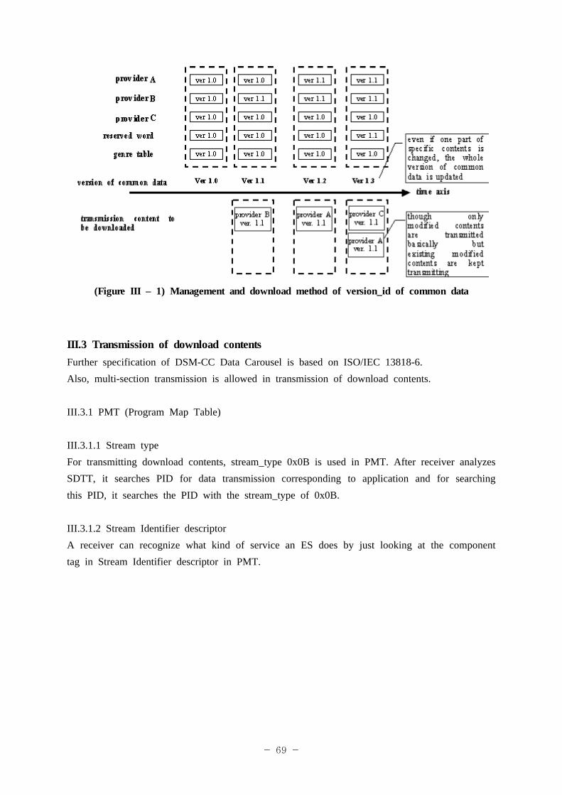
- 69 -
(Figure III – 1) Management and download method of version_id of common data
III.3 Transmission of download contentsFurther specification of DSM-CC Data Carousel is based on ISO/IEC 13818-6.Also, multi-section transmission is allowed in transmission of download contents.
III.3.1 PMT (Program Map Table)
III.3.1.1 Stream typeFor transmitting download contents, stream_type 0x0B is used in PMT. After receiver analyzes SDTT, it searches PID for data transmission corresponding to application and for searching this PID, it searches the PID with the stream_type of 0x0B.
III.3.1.2 Stream Identifier descriptorA receiver can recognize what kind of service an ES does by just looking at the component tag in Stream Identifier descriptor in PMT.
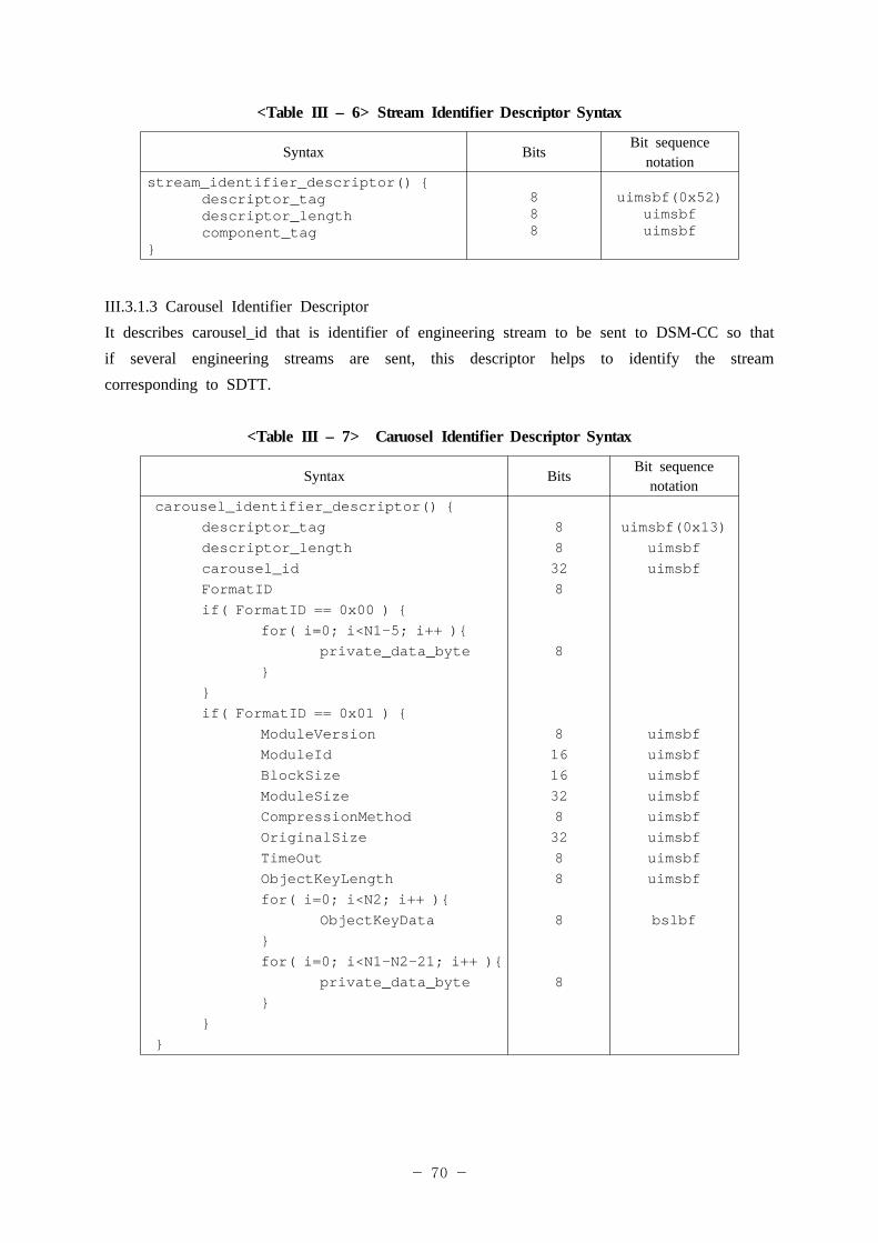
- 70 -
<Table III – 6> Stream Identifier Descriptor Syntax
Syntax BitsBit sequence
notationstream_identifier_descriptor() {
descriptor_tagdescriptor_lengthcomponent_tag
}
888
uimsbf(0x52)uimsbfuimsbf
III.3.1.3 Carousel Identifier DescriptorIt describes carousel_id that is identifier of engineering stream to be sent to DSM-CC so that if several engineering streams are sent, this descriptor helps to identify the stream corresponding to SDTT.
<Table III – 7> Caruosel Identifier Descriptor Syntax
Syntax BitsBit sequence
notationcarousel_identifier_descriptor() {
descriptor_tagdescriptor_lengthcarousel_idFormatIDif( FormatID == 0x00 ) {
for( i=0; i<N1-5; i++ ){private_data_byte
}}if( FormatID == 0x01 ) {
ModuleVersionModuleIdBlockSizeModuleSizeCompressionMethodOriginalSizeTimeOutObjectKeyLengthfor( i=0; i<N2; i++ ){
ObjectKeyData}for( i=0; i<N1-N2-21; i++ ){
private_data_byte}
}}
88328
8
816163283288
8
8
uimsbf(0x13)uimsbfuimsbf
uimsbfuimsbfuimsbfuimsbfuimsbfuimsbfuimsbfuimsbf
bslbf
- 71 -
descriptor_tag – 0x13carousel_id – 32 bits. Identifier for one downloadable engineering stream and it is used for searching corresponding stream in PMT that is notified in SDTT.FormatID – 0x00 (standard boot), 0x01 (enhanced boot). In case of download service, FormatID is always 0x00.ModuleVersion – The version of the module included in service gatewayModuleID – The same as ModuleID described in DII.BlockSize – The size of block in the moduleModuleSize – The size of the moduleCompressionMethod – Compression algorithm (RFC 1950)OriginalSize – The size of the module before compressionTimeOut –Time limit for collecting all blocks in the moduleObjectKeyData – Service gateway message (BIOP message)
III. 3.2 DII (Download Info Indication)DII message includes description on modules belonging to one group. Each module is described with several attribute values. These attribute values are moduleId, moduleSize, and moduleVersion and etc. and exist as the fileds of DII. Other module attributes are as follows.
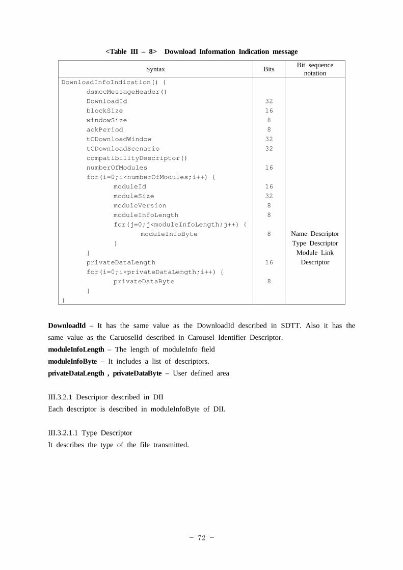
- 72 -
<Table III – 8> Download Information Indication message
Syntax Bits Bit sequence notation
DownloadInfoIndication() {dsmccMessageHeader()DownloadIdblockSizewindowSizeackPeriodtCDownloadWindowtCDownloadScenariocompatibilityDescriptor()numberOfModulesfor(i=0;i<numberOfModules;i++) {
moduleIdmoduleSizemoduleVersionmoduleInfoLengthfor(j=0;j<moduleInfoLength;j++) {
moduleInfoByte}
}privateDataLengthfor(i=0;i<privateDataLength;i++) {
privateDataByte}
}
3216883232 16 163288 8 16 8
Name DescriptorType Descriptor
Module Link Descriptor
DownloadId – It has the same value as the DownloadId described in SDTT. Also it has the same value as the CaruoselId described in Carousel Identifier Descriptor.moduleInfoLength – The length of moduleInfo fieldmoduleInfoByte – It includes a list of descriptors.privateDataLength , privateDataByte – User defined area
III.3.2.1 Descriptor described in DIIEach descriptor is described in moduleInfoByte of DII.
III.3.2.1.1 Type DescriptorIt describes the type of the file transmitted.
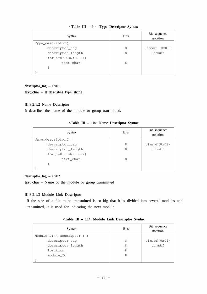
- 73 -
<Table III – 9> Type Descriptor Syntax
Syntax BitsBit sequence
notationType_descriptor() {
descriptor_tagdescriptor_lengthfor(i=0; i<N; i++){
text_char}
}
88
8
uimsbf (0x01)uimsbf
descriptor_tag – 0x01text_char – It describes type string.
III.3.2.1.2 Name DescriptorIt describes the name of the module or group transmitted.
<Table III – 10> Name Descriptor Syntax
Syntax BitsBit sequence
notationName_descriptor() {
descriptor_tagdescriptor_lengthfor(i=0; i<N; i++){
text_char}
}
88
8
uimsbf(0x02)uimsbf
descriptor_tag – 0x02text_char – Name of the module or group transmitted
III.3.2.1.3 Module Link DescriptorIf the size of a file to be transmitted is so big that it is divided into several modules and transmitted, it is used for indicating the next module.
<Table III – 11> Module Link Descriptor Syntax
Syntax BitsBit sequence
notationModule_Link_descriptor() {
descriptor_tagdescriptor_lengthPositionmodule_Id
}
8888
uimsbf(0x04)uimsbf
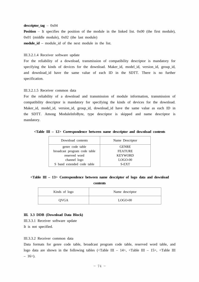
- 74 -
descriptor_tag – 0x04Position – It specifies the position of the module in the linked list. 0x00 (the first module), 0x01 (middle module), 0x02 (the last module)module_id – module_id of the next module in the list.
III.3.2.1.4 Receiver software updateFor the reliability of a download, transmission of compatibility descriptor is mandatory for specifying the kinds of devices for the download. Maker_id, model_id, version_id, group_id, and download_id have the same value of each ID in the SDTT. There is no further specification.
III.3.2.1.5 Receiver common dataFor the reliability of a download and transmission of module information, transmission of compatibility descriptor is mandatory for specifying the kinds of devices for the download. Maker_id, model_id, version_id, group_id, download_id have the same value as each ID in the SDTT. Among ModuleInfoByte, type descriptor is skipped and name descriptor is mandatory.
<Table III – 12> Correspondence between name descriptor and download contents
Download contents Name Descriptor
genre code tablebroadcast program code table
reserved word channel logo
S band extended code table
GENREFEATURE
KEYWORDLOGO-00
S-EXT
<Table III – 13> Correspondence between name descriptor of logo data and download contents
Kinds of logo Name descriptor
QVGA LOGO-00
III. 3.3 DDB (Download Data Block)III.3.3.1 Receiver software updateIt is not specified.
III.3.3.2 Receiver common dataData formats for genre code table, broadcast program code table, reserved word table, and logo data are shown in the following tables (<Table III – 14>, <Table III – 15>, <Table III – 16>).
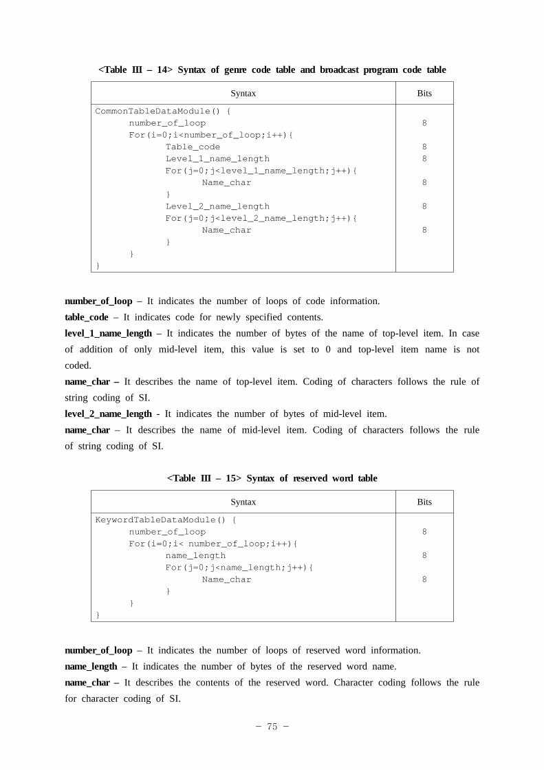
- 75 -
<Table III – 14> Syntax of genre code table and broadcast program code table
Syntax Bits
CommonTableDataModule() {number_of_loopFor(i=0;i<number_of_loop;i++){
Table_code Level_1_name_length
For(j=0;j<level_1_name_length;j++){ Name_char
}Level_2_name_lengthFor(j=0;j<level_2_name_length;j++){
Name_char}
}}
8
88
8
8
8
number_of_loop – It indicates the number of loops of code information.table_code – It indicates code for newly specified contents.level_1_name_length – It indicates the number of bytes of the name of top-level item. In case of addition of only mid-level item, this value is set to 0 and top-level item name is not coded.name_char – It describes the name of top-level item. Coding of characters follows the rule of string coding of SI. level_2_name_length - It indicates the number of bytes of mid-level item.name_char – It describes the name of mid-level item. Coding of characters follows the rule of string coding of SI.
<Table III – 15> Syntax of reserved word table
Syntax Bits
KeywordTableDataModule() {number_of_loopFor(i=0;i< number_of_loop;i++){
name_lengthFor(j=0;j<name_length;j++){
Name_char}
}}
8
8
8
number_of_loop – It indicates the number of loops of reserved word information.name_length – It indicates the number of bytes of the reserved word name.name_char – It describes the contents of the reserved word. Character coding follows the rule for character coding of SI.
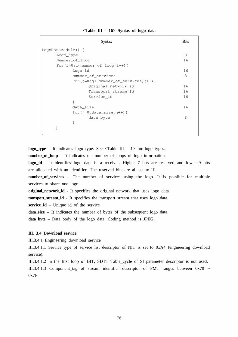
- 76 -
<Table III – 16> Syntax of logo data
Syntax Bits
LogoDataModule() {Logo_typeNumber_of_loopFor(i=0;i<number_of_loop;i++){
Logo_idNumber_of_servicesFor(j=0;j< Number_of_services;j++){
Original_network_idTransport_stream_idService_id
}data_sizefor(j=0;data_size;j++){
data_byte }
}}
816
168
161616
16
8
logo_type – It indicates logo type. See <Table III – 1> for logo types.number_of_loop – It indicates the number of loops of logo information.logo_id – It identifies logo data in a receiver. Higher 7 bits are reserved and lower 9 bits are allocated with an identifier. The reserved bits are all set to '1'.number_of_services – The number of services using the logo. It is possible for multiple services to share one logo.original_network_id - It specifies the original network that uses logo data.transport_stream_id - It specifies the transport stream that uses logo data.service_id – Unique id of the servicedata_size – It indicates the number of bytes of the subsequent logo data. data_byte – Data body of the logo data. Coding method is JPEG.
III. 3.4 Download serviceIII.3.4.1 Engineering download serviceIII.3.4.1.1 Service_type of service list descriptor of NIT is set to 0xA4 (engineering download service).III.3.4.1.2 In the first loop of BIT, SDTT Table_cycle of SI parameter descriptor is not used.III.3.4.1.3 Component_tag of stream identifier descriptor of PMT ranges between 0x70 ~ 0x7F.
- 77 -
III.3.4.1.4 Only ESs of engineering streams that are transmitted are registered to PMT. III.3.4.1.5 Channel number of download service channel ranges between number 6000 ~ number 65535.III.3.4.1.6 If several download streams are sent through a single service channel at the same time, they should have component_tag values that are different from each other within range. III.3.4.1.7 In a download service, there are occasions where PCR is not sent.
III.3.4.2 Program specific information/service information to be transmittedIII.3.4.2.1 When no download content is transmitted, PMT is not sent.III.3.4.2.2 When download contents are not transmitted at all, SDTT is not sent.
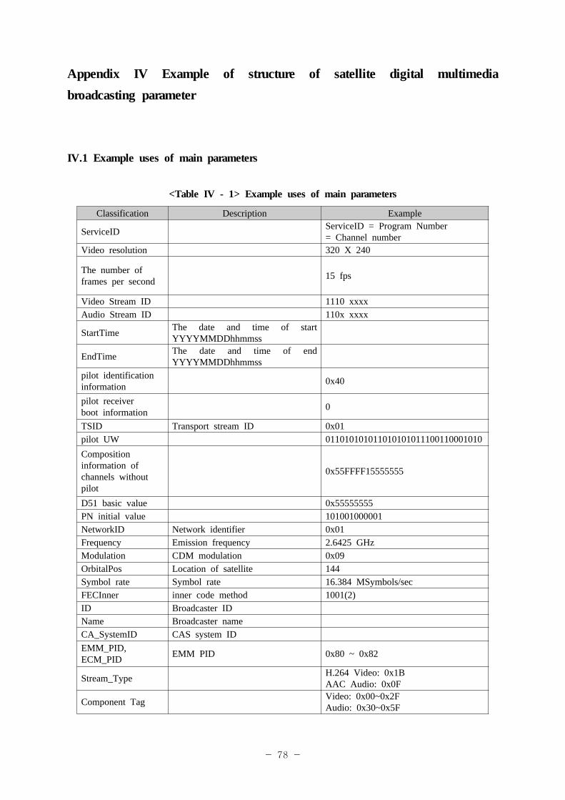
- 78 -
Appendix IV Example of structure of satellite digital multimedia broadcasting parameter
IV.1 Example uses of main parameters
<Table IV - 1> Example uses of main parameters
Classification Description Example
ServiceID ServiceID = Program Number = Channel number
Video resolution 320 X 240
The number of frames per second 15 fps
Video Stream ID 1110 xxxxAudio Stream ID 110x xxxx
StartTime The date and time of start YYYYMMDDhhmmss
EndTime The date and time of end YYYYMMDDhhmmss
pilot identification information 0x40
pilot receiverboot information 0
TSID Transport stream ID 0x01pilot UW 011010101011010101011100110001010Composition information of channels without pilot
0x55FFFF15555555
D51 basic value 0x55555555PN initial value 101001000001NetworkID Network identifier 0x01Frequency Emission frequency 2.6425 GHzModulation CDM modulation 0x09OrbitalPos Location of satellite 144Symbol rate Symbol rate 16.384 MSymbols/secFECInner inner code method 1001(2)ID Broadcaster IDName Broadcaster nameCA_SystemID CAS system IDEMM_PID, ECM_PID EMM PID 0x80 ~ 0x82
Stream_Type H.264 Video: 0x1BAAC Audio: 0x0F
Component Tag Video: 0x00~0x2FAudio: 0x30~0x5F
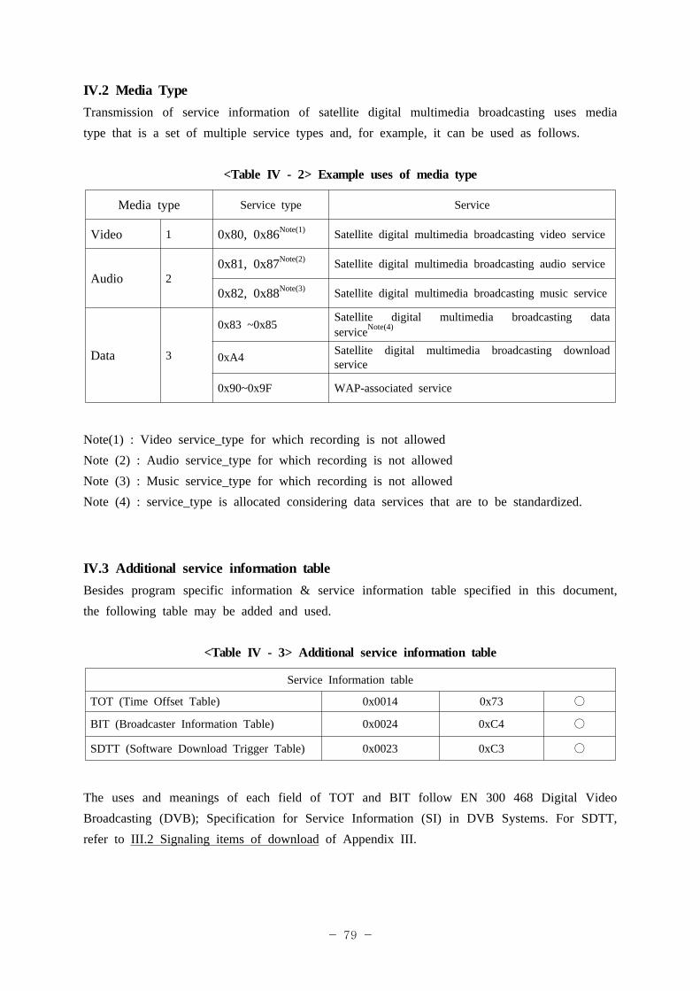
- 79 -
IV.2 Media TypeTransmission of service information of satellite digital multimedia broadcasting uses media type that is a set of multiple service types and, for example, it can be used as follows.
<Table IV - 2> Example uses of media type
Media type Service type Service
Video 1 0x80, 0x86Note(1) Satellite digital multimedia broadcasting video service
Audio 20x81, 0x87Note(2) Satellite digital multimedia broadcasting audio service
0x82, 0x88Note(3) Satellite digital multimedia broadcasting music service
Data 3
0x83 ~0x85 Satellite digital multimedia broadcasting data serviceNote(4)
0xA4 Satellite digital multimedia broadcasting download service
0x90~0x9F WAP-associated service
Note(1) : Video service_type for which recording is not allowedNote (2) : Audio service_type for which recording is not allowedNote (3) : Music service_type for which recording is not allowedNote (4) : service_type is allocated considering data services that are to be standardized.
IV.3 Additional service information tableBesides program specific information & service information table specified in this document, the following table may be added and used.
<Table IV - 3> Additional service information table
Service Information table
TOT (Time Offset Table) 0x0014 0x73 ○
BIT (Broadcaster Information Table) 0x0024 0xC4 ○
SDTT (Software Download Trigger Table) 0x0023 0xC3 ○
The uses and meanings of each field of TOT and BIT follow EN 300 468 Digital Video Broadcasting (DVB); Specification for Service Information (SI) in DVB Systems. For SDTT, refer to III.2 Signaling items of download of Appendix III.
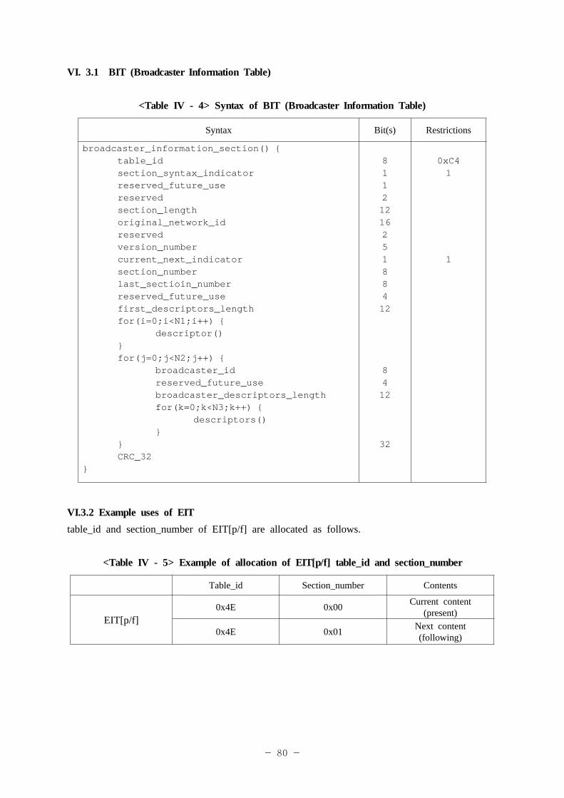
- 80 -
VI. 3.1 BIT (Broadcaster Information Table)
<Table IV - 4> Syntax of BIT (Broadcaster Information Table)
Syntax Bit(s) Restrictions
broadcaster_information_section() {table_idsection_syntax_indicatorreserved_future_usereserved section_lengthoriginal_network_idreserved version_numbercurrent_next_indicatorsection_numberlast_sectioin_numberreserved_future_usefirst_descriptors_lengthfor(i=0;i<N1;i++) {
descriptor()}for(j=0;j<N2;j++) {
broadcaster_idreserved_future_usebroadcaster_descriptors_lengthfor(k=0;k<N3;k++) {
descriptors()}
}CRC_32
}
8112121625188412
8412
32
0xC41
1
VI.3.2 Example uses of EITtable_id and section_number of EIT[p/f] are allocated as follows.
<Table IV - 5> Example of allocation of EIT[p/f] table_id and section_number
Table_id Section_number Contents
EIT[p/f]0x4E 0x00 Current content
(present)
0x4E 0x01 Next content(following)
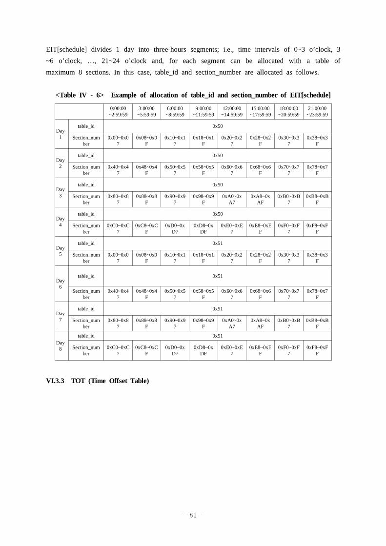
- 81 -
EIT[schedule] divides 1 day into three-hours segments; i.e., time intervals of 0~3 o’clock, 3 ~6 o’clock, …, 21~24 o’clock and, for each segment can be allocated with a table of maximum 8 sections. In this case, table_id and section_number are allocated as follows.
<Table IV - 6> Example of allocation of table_id and section_number of EIT[schedule]
0:00:00~2:59:59
3:00:00~5:59:59
6:00:00~8:59:59
9:00:00~11:59:59
12:00:00~14:59:59
15:00:00~17:59:59
18:00:00~20:59:59
21:00:00~23:59:59
Day1
table_id 0x50
Section_number
0x00~0x07
0x08~0x0F
0x10~0x17
0x18~0x1F
0x20~0x27
0x28~0x2F
0x30~0x37
0x38~0x3F
Day2
table_id 0x50
Section_number
0x40~0x47
0x48~0x4F
0x50~0x57
0x58~0x5F
0x60~0x67
0x68~0x6F
0x70~0x77
0x78~0x7F
Day3
table_id 0x50
Section_number
0x80~0x87
0x88~0x8F
0x90~0x97
0x98~0x9F
0xA0~0xA7
0xA8~0xAF
0xB0~0xB7
0xB8~0xBF
Day4
table_id 0x50
Section_number
0xC0~0xC7
0xC8~0xCF
0xD0~0xD7
0xD8~0xDF
0xE0~0xE7
0xE8~0xEF
0xF0~0xF7
0xF8~0xFF
Day5
table_id 0x51
Section_number
0x00~0x07
0x08~0x0F
0x10~0x17
0x18~0x1F
0x20~0x27
0x28~0x2F
0x30~0x37
0x38~0x3F
Day6
table_id 0x51
Section_number
0x40~0x47
0x48~0x4F
0x50~0x57
0x58~0x5F
0x60~0x67
0x68~0x6F
0x70~0x77
0x78~0x7F
Day7
table_id 0x51
Section_number
0x80~0x87
0x88~0x8F
0x90~0x97
0x98~0x9F
0xA0~0xA7
0xA8~0xAF
0xB0~0xB7
0xB8~0xBF
Day8
table_id 0x51
Section_number
0xC0~0xC7
0xC8~0xCF
0xD0~0xD7
0xD8~0xDF
0xE0~0xE7
0xE8~0xEF
0xF0~0xF7
0xF8~0xFF
VI.3.3 TOT (Time Offset Table)
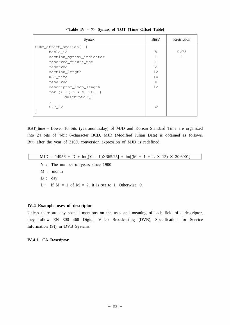
- 82 -
<Table IV – 7> Syntax of TOT (Time Offset Table)
Syntax Bit(s) Restriction
time_offset_section() {table_idsection_syntax_indicatorreserved_future_usereservedsection_lengthKST_timereserveddescriptor_loop_lengthfor (i 0 ; i < N; i++) {
descriptor()}CRC_32
}
81121240412
32
0x731
KST_time - Lower 16 bits (year,month,day) of MJD and Korean Standard Time are organized into 24 bits of 4-bit 6-character BCD. MJD (Modified Julian Date) is obtained as follows. But, after the year of 2100, conversion expression of MJD is redefined.
MJD = 14956 + D + int[(Y – L)X365.25] + int[(M + 1 + L X 12) X 30.6001]
Y : The number of years since 1900M : monthD : dayL : If M = 1 of M = 2, it is set to 1. Otherwise, 0.
IV.4 Example uses of descriptorUnless there are any special mentions on the uses and meaning of each field of a descriptor, they follow EN 300 468 Digital Video Broadcasting (DVB); Specification for Service Information (SI) in DVB Systems.
IV.4.1 CA Descriptor
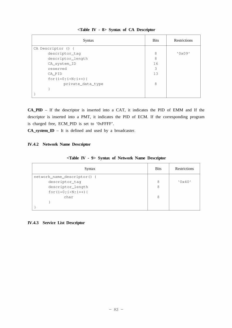
- 83 -
<Table IV - 8> Syntax of CA Descriptor
Syntax Bits Restrictions
CA Descriptor () {descriptor_tagdescriptor_lengthCA_system_IDreservedCA_PIDfor(i=0;i<N;i++){
private_data_type}
}
8816313
8
‘0x09’
CA_PID – If the descriptor is inserted into a CAT, it indicates the PID of EMM and If the descriptor is inserted into a PMT, it indicates the PID of ECM. If the corresponding program is charged free, ECM_PID is set to ‘0xFFFF’.CA_system_ID – It is defined and used by a broadcaster.
IV.4.2 Network Name Descriptor
<Table IV - 9> Syntax of Network Name Descriptor
Syntax Bits Restrictions
network_name_descriptor() {descriptor_tagdescriptor_lengthfor(i=0;i<N;i++){
char}
}
88
8
‘0x40’
IV.4.3 Service List Descriptor
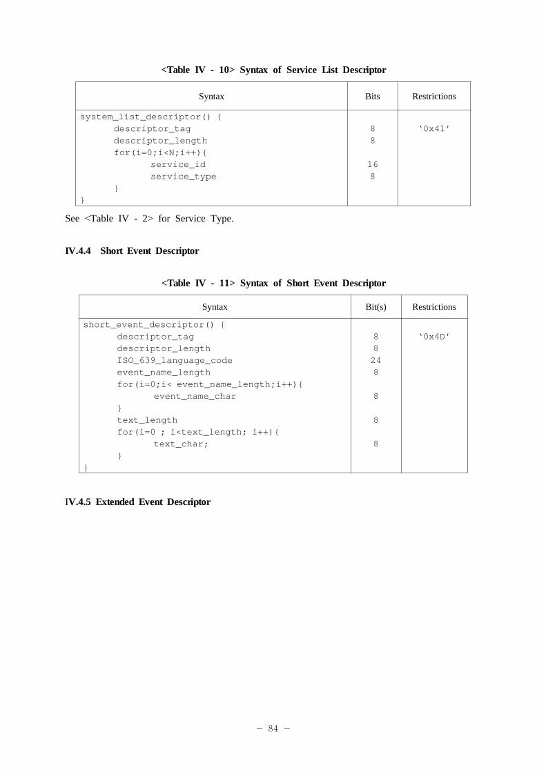
- 84 -
<Table IV - 10> Syntax of Service List Descriptor
Syntax Bits Restrictions
system_list_descriptor() {descriptor_tagdescriptor_lengthfor(i=0;i<N;i++){
service_idservice_type
}}
88
168
‘0x41’
See <Table IV - 2> for Service Type.
IV.4.4 Short Event Descriptor
<Table IV - 11> Syntax of Short Event Descriptor
Syntax Bit(s) Restrictions
short_event_descriptor() {descriptor_tagdescriptor_lengthISO_639_language_codeevent_name_lengthfor(i=0;i< event_name_length;i++){
event_name_char}text_lengthfor(i=0 ; i<text_length; i++){
text_char;}
}
88248
8
8
8
‘0x4D’
IV.4.5 Extended Event Descriptor
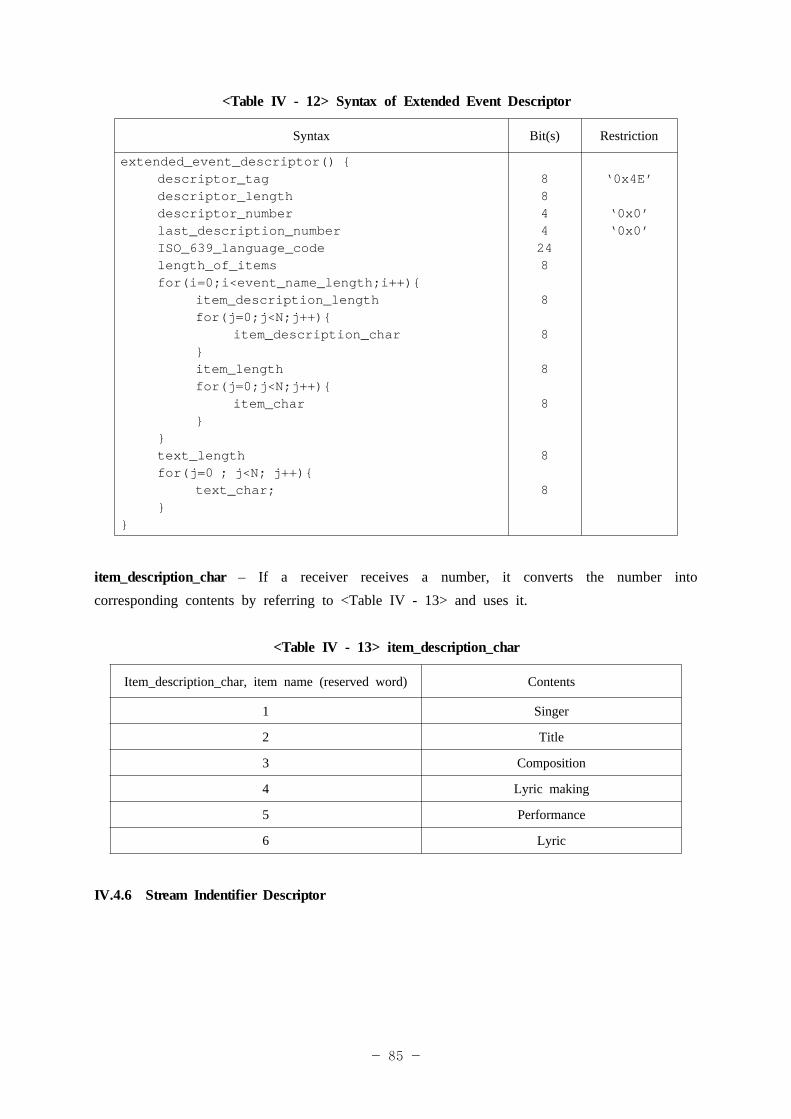
- 85 -
<Table IV - 12> Syntax of Extended Event Descriptor
Syntax Bit(s) Restriction
extended_event_descriptor() {descriptor_tagdescriptor_lengthdescriptor_numberlast_description_numberISO_639_language_codelength_of_itemsfor(i=0;i<event_name_length;i++){
item_description_lengthfor(j=0;j<N;j++){
item_description_char}item_lengthfor(j=0;j<N;j++){
item_char}
}text_lengthfor(j=0 ; j<N; j++){
text_char;}
}
8844248
8
8
8
8
8
8
‘0x4E’
‘0x0’‘0x0’
item_description_char – If a receiver receives a number, it converts the number into corresponding contents by referring to <Table IV - 13> and uses it.
<Table IV - 13> item_description_char
Item_description_char, item name (reserved word) Contents
1 Singer
2 Title
3 Composition
4 Lyric making
5 Performance
6 Lyric
IV.4.6 Stream Indentifier Descriptor
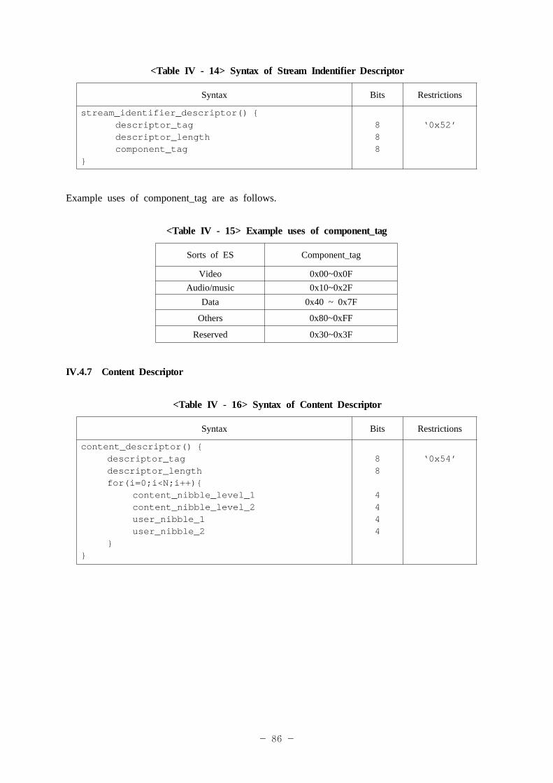
- 86 -
<Table IV - 14> Syntax of Stream Indentifier Descriptor
Syntax Bits Restrictions
stream_identifier_descriptor() {descriptor_tagdescriptor_lengthcomponent_tag
}
888
‘0x52’
Example uses of component_tag are as follows.
<Table IV - 15> Example uses of component_tag
Sorts of ES Component_tag
Video 0x00~0x0FAudio/music 0x10~0x2F
Data 0x40 ~ 0x7F
Others 0x80~0xFF
Reserved 0x30~0x3F
IV.4.7 Content Descriptor
<Table IV - 16> Syntax of Content Descriptor
Syntax Bits Restrictions
content_descriptor() {descriptor_tagdescriptor_lengthfor(i=0;i<N;i++){
content_nibble_level_1content_nibble_level_2user_nibble_1user_nibble_2
}}
88
4444
‘0x54’
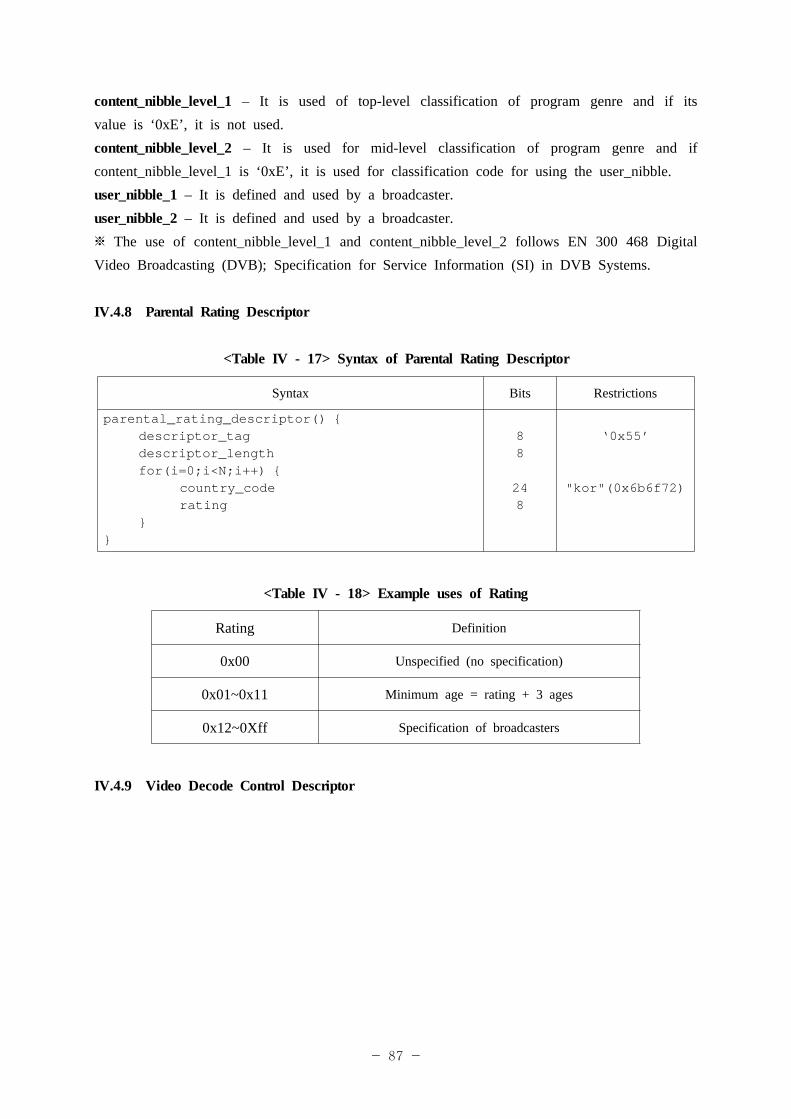
- 87 -
content_nibble_level_1 – It is used of top-level classification of program genre and if its value is ‘0xE’, it is not used.content_nibble_level_2 – It is used for mid-level classification of program genre and if content_nibble_level_1 is ‘0xE’, it is used for classification code for using the user_nibble.user_nibble_1 – It is defined and used by a broadcaster.user_nibble_2 – It is defined and used by a broadcaster.※ The use of content_nibble_level_1 and content_nibble_level_2 follows EN 300 468 Digital Video Broadcasting (DVB); Specification for Service Information (SI) in DVB Systems.
IV.4.8 Parental Rating Descriptor
<Table IV - 17> Syntax of Parental Rating Descriptor
Syntax Bits Restrictions
parental_rating_descriptor() {descriptor_tagdescriptor_lengthfor(i=0;i<N;i++) {
country_coderating
}}
88
248
‘0x55’
"kor"(0x6b6f72)
<Table IV - 18> Example uses of Rating
Rating Definition
0x00 Unspecified (no specification)
0x01~0x11 Minimum age = rating + 3 ages
0x12~0Xff Specification of broadcasters
IV.4.9 Video Decode Control Descriptor
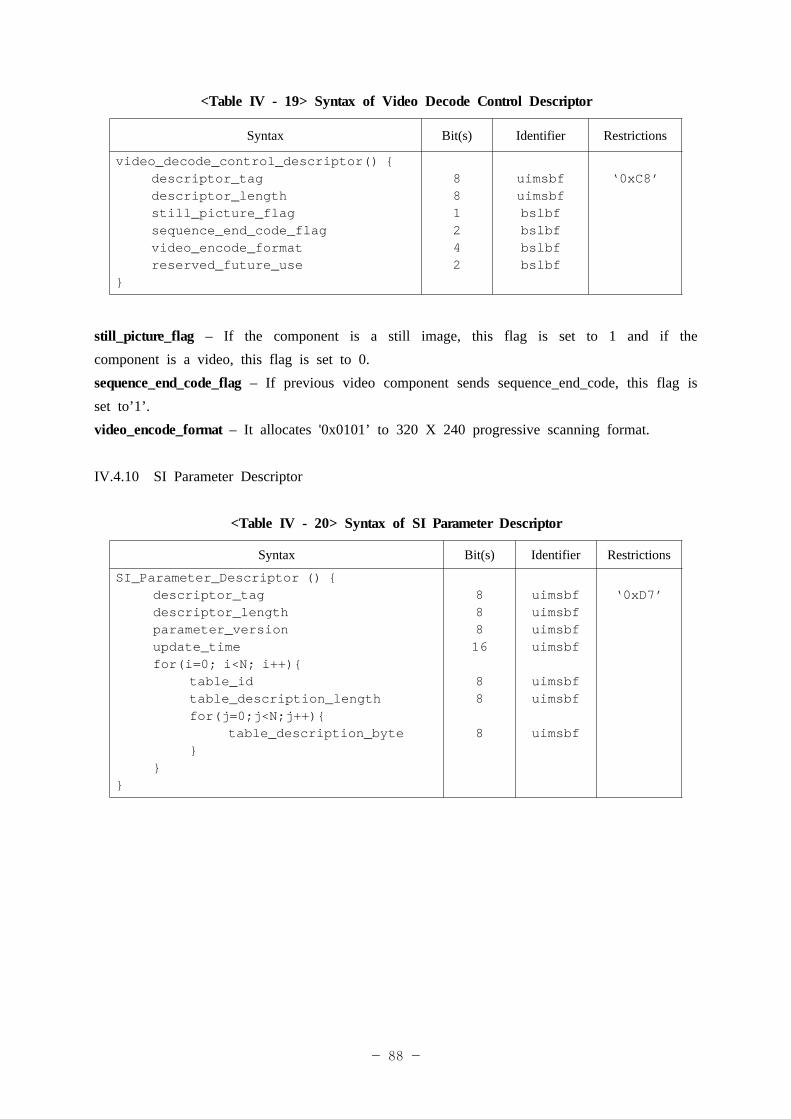
- 88 -
<Table IV - 19> Syntax of Video Decode Control Descriptor
Syntax Bit(s) Identifier Restrictions
video_decode_control_descriptor() {descriptor_tagdescriptor_lengthstill_picture_flagsequence_end_code_flagvideo_encode_formatreserved_future_use
}
881242
uimsbfuimsbfbslbfbslbfbslbfbslbf
‘0xC8’
still_picture_flag – If the component is a still image, this flag is set to 1 and if the component is a video, this flag is set to 0.sequence_end_code_flag – If previous video component sends sequence_end_code, this flag is set to’1’. video_encode_format – It allocates '0x0101’ to 320 X 240 progressive scanning format.
IV.4.10 SI Parameter Descriptor
<Table IV - 20> Syntax of SI Parameter Descriptor
Syntax Bit(s) Identifier Restrictions
SI_Parameter_Descriptor () {descriptor_tagdescriptor_lengthparameter_versionupdate_timefor(i=0; i<N; i++){
table_idtable_description_lengthfor(j=0;j<N;j++){
table_description_byte }
}}
88816
88
8
uimsbfuimsbfuimsbfuimsbf
uimsbfuimsbf
uimsbf
‘0xD7’
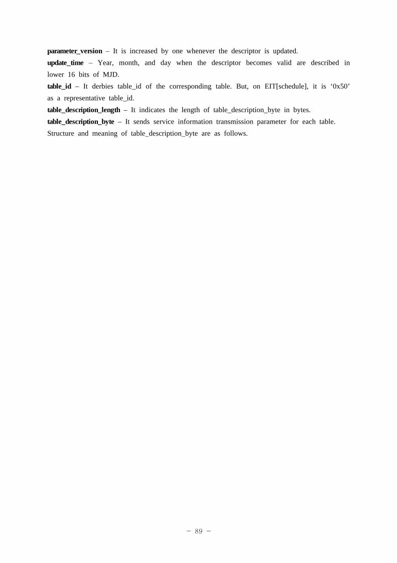
- 89 -
parameter_version – It is increased by one whenever the descriptor is updated.update_time – Year, month, and day when the descriptor becomes valid are described in lower 16 bits of MJD.table_id – It derbies table_id of the corresponding table. But, on EIT[schedule], it is ‘0x50’ as a representative table_id.table_description_length – It indicates the length of table_description_byte in bytes.table_description_byte – It sends service information transmission parameter for each table.Structure and meaning of table_description_byte are as follows.
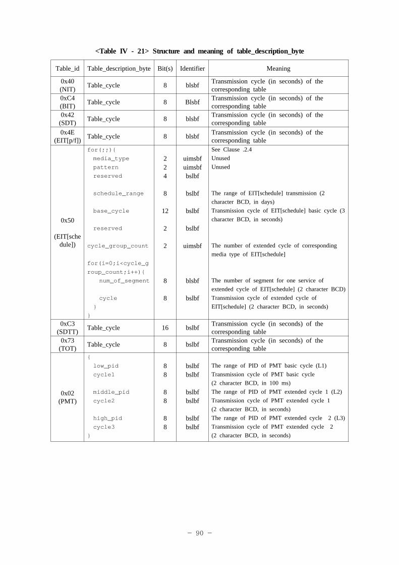
- 90 -
<Table IV - 21> Structure and meaning of table_description_byte
Table_id Table_description_byte Bit(s) Identifier Meaning
0x40 (NIT) Table_cycle 8 blsbf Transmission cycle (in seconds) of the
corresponding table0xC4 (BIT) Table_cycle 8 Blsbf Transmission cycle (in seconds) of the
corresponding table0x42
(SDT) Table_cycle 8 blsbf Transmission cycle (in seconds) of the corresponding table
0x4E(EIT[p/f]) Table_cycle 8 blsbf Transmission cycle (in seconds) of the
corresponding table
0x50
(EIT[schedule])
for(;;){ media_type
pattern
reserved
schedule_range
base_cycle
reserved
cycle_group_count
for(i=0;i<cycle_g
roup_count;i++){
num_of_segment
cycle
}}
224
8
12
2
2
8
8
uimsbfuimsbfbslbf
bslbf
bslbf
bslbf
uimsbf
blsbf
bslbf
See Clause .2.4UnusedUnused
The range of EIT[schedule] transmission (2 character BCD, in days)Transmission cycle of EIT[schedule] basic cycle (3 character BCD, in seconds)
The number of extended cycle of corresponding media type of EIT[schedule]
The number of segment for one service of extended cycle of EIT[schedule] (2 character BCD)Transmission cycle of extended cycle of EIT[schedule] (2 character BCD, in seconds)
0xC3 (SDTT) Table_cycle 16 bslbf Transmission cycle (in seconds) of the
corresponding table0x73
(TOT) Table_cycle 8 bslbf Transmission cycle (in seconds) of the corresponding table
0x02 (PMT)
{
low_pid
cycle1
middle_pid
cycle2
high_pid
cycle3}
88
88
88
bslbfbslbf
bslbfbslbf
bslbfbslbf
The range of PID of PMT basic cycle (L1)Transmission cycle of PMT basic cycle (2 character BCD, in 100 ms)The range of PID of PMT extended cycle 1 (L2)Transmission cycle of PMT extended cycle 1 (2 character BCD, in seconds)The range of PID of PMT extended cycle 2 (L3)Transmission cycle of PMT extended cycle 2 (2 character BCD, in seconds)
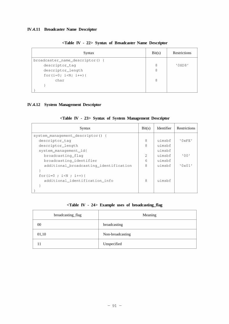
- 91 -
IV.4.11 Broadcaster Name Descriptor
<Table IV - 22> Syntax of Broadcaster Name Descriptor
Syntax Bit(s) Restrictions
broadcaster_name_descriptor() {descriptor_tagdescriptor_lengthfor(i=0; i<N; i++){
char}
}
88
8
‘0XD8’
IV.4.12 System Management Descriptor
<Table IV - 23> Syntax of System Management Descriptor
Syntax Bit(s) Identifier Restrictions
system_management_descriptor() {descriptor_tagdescriptor_lengthsystem_management_id{
broadcasting_flagbroadcasting_identifieradditional_broadcasting_identification
}for(i=0 ; i<N ; i++){
additional_identification_info}
}
88
268
8
uimsbfuimsbfuimsbfuimsbfuimsbfuimsbf
uimsbf
‘0xFE’
‘00’
‘0x01’
<Table IV - 24> Example uses of broadcasting_flag
broadcasting_flag Meaning
00 broadcasting
01,10 Non-broadcasting
11 Unspecified
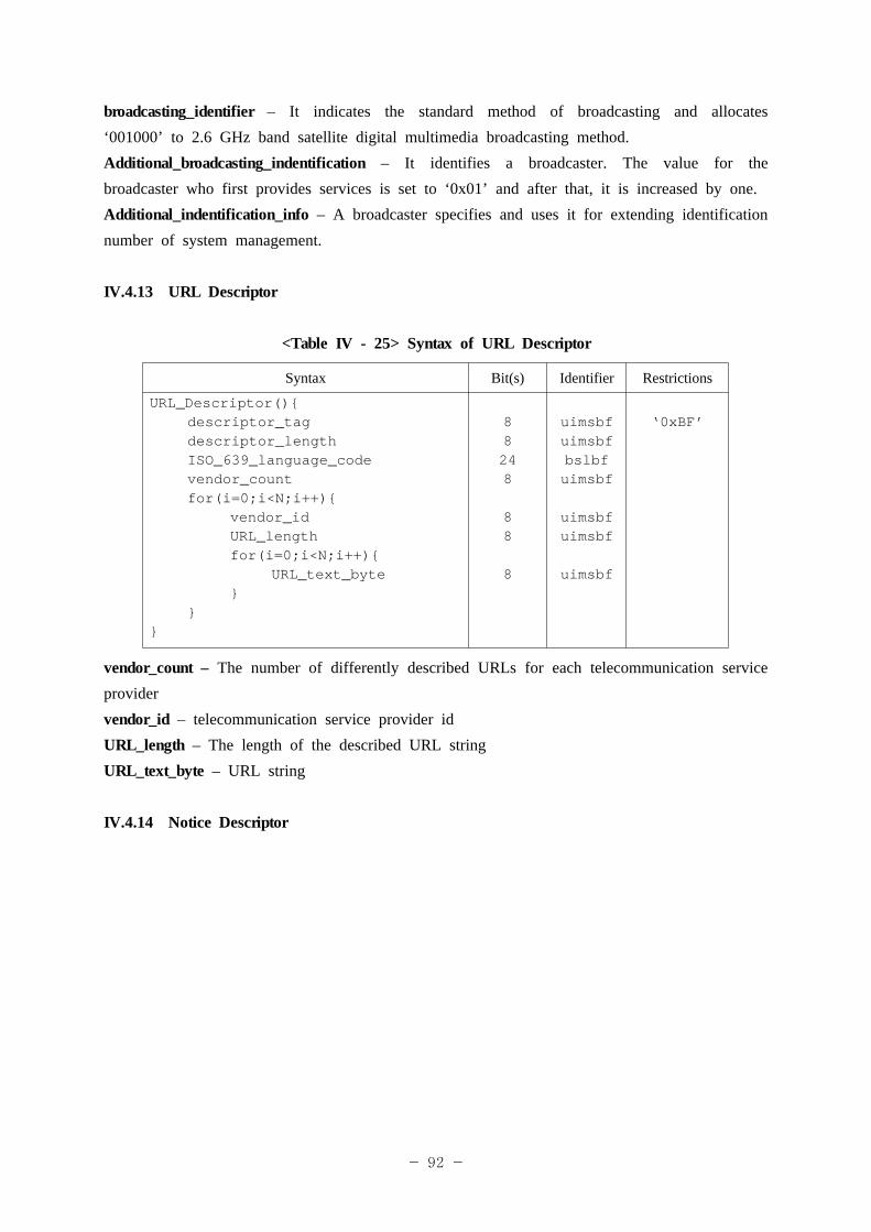
- 92 -
broadcasting_identifier – It indicates the standard method of broadcasting and allocates ‘001000’ to 2.6 GHz band satellite digital multimedia broadcasting method.Additional_broadcasting_indentification – It identifies a broadcaster. The value for the broadcaster who first provides services is set to ‘0x01’ and after that, it is increased by one.Additional_indentification_info – A broadcaster specifies and uses it for extending identification number of system management.
IV.4.13 URL Descriptor
<Table IV - 25> Syntax of URL Descriptor
Syntax Bit(s) Identifier Restrictions
URL_Descriptor(){descriptor_tagdescriptor_lengthISO_639_language_codevendor_countfor(i=0;i<N;i++){
vendor_idURL_lengthfor(i=0;i<N;i++){
URL_text_byte}
}}
88248
88
8
uimsbfuimsbfbslbfuimsbf
uimsbfuimsbf
uimsbf
‘0xBF’
vendor_count – The number of differently described URLs for each telecommunication service providervendor_id – telecommunication service provider idURL_length – The length of the described URL stringURL_text_byte – URL string
IV.4.14 Notice Descriptor
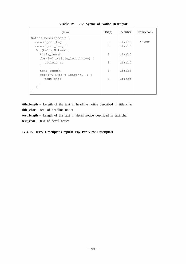
- 93 -
<Table IV - 26> Syntax of Notice Descriptor
Syntax Bit(s) Identifier Restrictions
Notice_Descriptor() {descriptor_tagdescriptor_lengthfor(k=0;k<N;k++) {
title_lengthfor(i=0;i<title_length;i++) {
title_char}text_lengthfor(i=0;i<text_length;i++) {
text_char}
}}
88
8
8
8
8
uimsbfuimsbf
uimsbf
uimsbf
uimsbf
uimsbf
‘0xBE’
title_length – Length of the text in headline notice described in title_chartitle_char – text of headline noticetext_length – Length of the text in detail notice described in text_chartext_char – text of detail notice
IV.4.15 IPPV Descriptor (Impulse Pay Per View Descriptor)
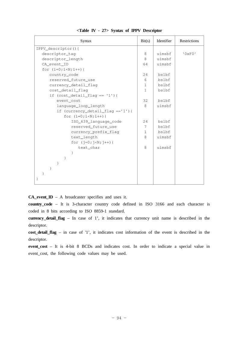
- 94 -
<Table IV - 27> Syntax of IPPV Descriptor
Syntax Bit(s) Identifier Restrictions
IPPV_descriptor(){descriptor_tagdescriptor_lengthCA_event_IDfor (i=0;i<N;i++){
country_codereserved_future_usecurrency_detail_flagcost_detail_flagif (cost_detail_flag == ‘1’){
event_costlanguage_loop_lengthif (currency_detail_flag ==’1’){
for (i=0;i<N;i++){ISO_639_language_codereserved_future_usecurrency_prefix_flagtext_lengthfor (j=0;j<N;j++){
text_char}
}}
}}
}
8864
24611
328
24718
8
uimsbfuimsbfuimsbf
bslbfbslbfbslbfbslbf
bslbfuimsbf
bslbfbslbfbslbfuimsbf
uimsbf
‘0xF0’
CA_event_ID – A broadcaster specifies and uses it.country_code – It is 3-character country code defined in ISO 3166 and each character is coded in 8 bits according to ISO 8859-1 standard.currency_detail_flag – In case of 1’, it indicates that currency unit name is described in the descriptor. cost_detail_flag – in case of '1’, it indicates cost information of the event is described in the descriptor.event_cost – It is 4-bit 8 BCDs and indicates cost. In order to indicate a special value in event_cost, the following code values may be used.
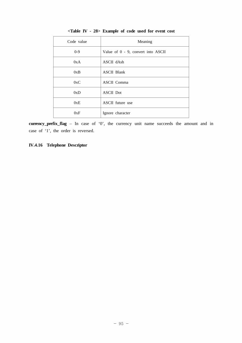
- 95 -
<Table IV - 28> Example of code used for event cost
Code value Meaning
0-9 Value of 0 - 9, convert into ASCII
0xA ASCII dAsh
0xB ASCII Blank
0xC ASCII Comma
0xD ASCII Dot
0xE ASCII future use
0xF Ignore character
currency_prefix_flag – In case of ‘0’, the currency unit name succeeds the amount and in case of ‘1’, the order is reversed.
IV.4.16 Telephone Descriptor
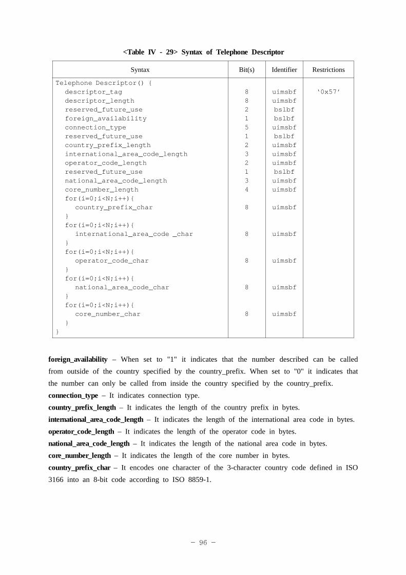
- 96 -
<Table IV - 29> Syntax of Telephone Descriptor
Syntax Bit(s) Identifier Restrictions
Telephone Descriptor() {descriptor_tagdescriptor_lengthreserved_future_useforeign_availabilityconnection_typereserved_future_usecountry_prefix_lengthinternational_area_code_lengthoperator_code_lengthreserved_future_usenational_area_code_lengthcore_number_lengthfor(i=0;i<N;i++){
country_prefix_char}for(i=0;i<N;i++){
international_area_code _char}for(i=0;i<N;i++){
operator_code_char}for(i=0;i<N;i++){
national_area_code_char}for(i=0;i<N;i++){
core_number_char}
}
882151232134
8
8
8
8
8
uimsbfuimsbfbslbfbslbfuimsbfbslbfuimsbfuimsbfuimsbfbslbfuimsbfuimsbf
uimsbf
uimsbf
uimsbf
uimsbf
uimsbf
‘0x57’
foreign_availability – When set to "1" it indicates that the number described can be called from outside of the country specified by the country_prefix. When set to "0" it indicates that the number can only be called from inside the country specified by the country_prefix.connection_type – It indicates connection type.country_prefix_length – It indicates the length of the country prefix in bytes.international_area_code_length – It indicates the length of the international area code in bytes.operator_code_length – It indicates the length of the operator code in bytes.national_area_code_length – It indicates the length of the national area code in bytes.core_number_length – It indicates the length of the core number in bytes.country_prefix_char – It encodes one character of the 3-character country code defined in ISO 3166 into an 8-bit code according to ISO 8859-1.
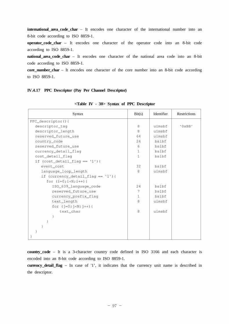
- 97 -
international_area_code_char – It encodes one character of the international number into an 8-bit code according to ISO 8859-1.operator_code_char – It encodes one character of the operator code into an 8-bit code according to ISO 8859-1.national_area_code_char – It encodes one character of the national area code into an 8-bit code according to ISO 8859-1.core_number_char – It encodes one character of the core number into an 8-bit code according to ISO 8859-1.
IV.4.17 PPC Descriptor (Pay Per Channel Descriptor)
<Table IV - 30> Syntax of PPC Descriptor
Syntax Bit(s) Identifier Restrictions
PPC_descriptor(){descriptor_tagdescriptor_lengthreserved_future_usecountry_codereserved_future_usecurrency_detail_flagcost_detail_flagif (cost_detail_flag == ‘1’){
event_costlanguage_loop_lengthif (currency_detail_flag == ‘1’){
for (i=0;i<N;i++){ISO_639_language_codereserved_future_usecurrency_prefix_flagtext_lengthfor (j=0;j<N;j++){
text_char}
}}
}}
886424611
328
24718
8
uimsbfuimsbfuimsbfbslbfbslbfbslbfbslbf
bslbfuimsbf
bslbfbslbfbslbfuimsbf
uimsbf
‘0xBB’
country_code – It is a 3-character country code defined in ISO 3166 and each character is encoded into an 8-bit code according to ISO 8859-1.currency_detail_flag – In case of '1’, it indicates that the currency unit name is described in the descriptor.
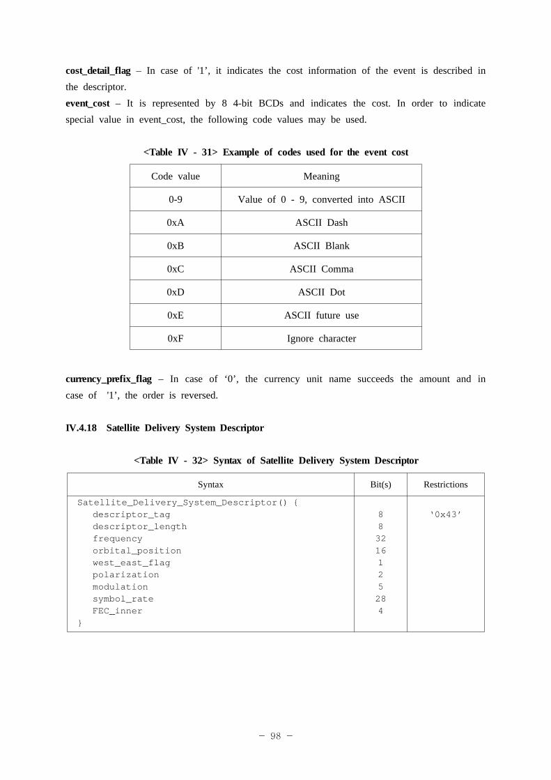
- 98 -
cost_detail_flag – In case of '1’, it indicates the cost information of the event is described in the descriptor.event_cost – It is represented by 8 4-bit BCDs and indicates the cost. In order to indicate special value in event_cost, the following code values may be used.
<Table IV - 31> Example of codes used for the event cost
Code value Meaning
0-9 Value of 0 - 9, converted into ASCII
0xA ASCII Dash
0xB ASCII Blank
0xC ASCII Comma
0xD ASCII Dot
0xE ASCII future use
0xF Ignore character
currency_prefix_flag – In case of ‘0’, the currency unit name succeeds the amount and in case of '1’, the order is reversed.
IV.4.18 Satellite Delivery System Descriptor
<Table IV - 32> Syntax of Satellite Delivery System Descriptor
Syntax Bit(s) Restrictions
Satellite_Delivery_System_Descriptor() {descriptor_tagdescriptor_lengthfrequencyorbital_positionwest_east_flagpolarizationmodulationsymbol_rateFEC_inner
}
883216125284
‘0x43’
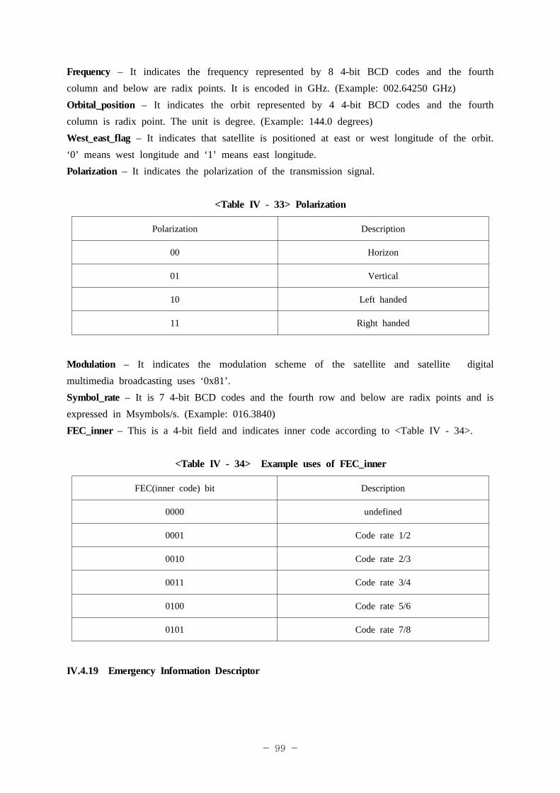
- 99 -
Frequency – It indicates the frequency represented by 8 4-bit BCD codes and the fourth column and below are radix points. It is encoded in GHz. (Example: 002.64250 GHz)Orbital_position – It indicates the orbit represented by 4 4-bit BCD codes and the fourth column is radix point. The unit is degree. (Example: 144.0 degrees)West_east_flag – It indicates that satellite is positioned at east or west longitude of the orbit. ‘0’ means west longitude and ‘1’ means east longitude.Polarization – It indicates the polarization of the transmission signal.
<Table IV - 33> Polarization
Polarization Description
00 Horizon
01 Vertical
10 Left handed
11 Right handed
Modulation – It indicates the modulation scheme of the satellite and satellite digital multimedia broadcasting uses ‘0x81’.Symbol_rate – It is 7 4-bit BCD codes and the fourth row and below are radix points and is expressed in Msymbols/s. (Example: 016.3840)FEC_inner – This is a 4-bit field and indicates inner code according to <Table IV - 34>.
<Table IV - 34> Example uses of FEC_inner
FEC(inner code) bit Description
0000 undefined
0001 Code rate 1/2
0010 Code rate 2/3
0011 Code rate 3/4
0100 Code rate 5/6
0101 Code rate 7/8
IV.4.19 Emergency Information Descriptor
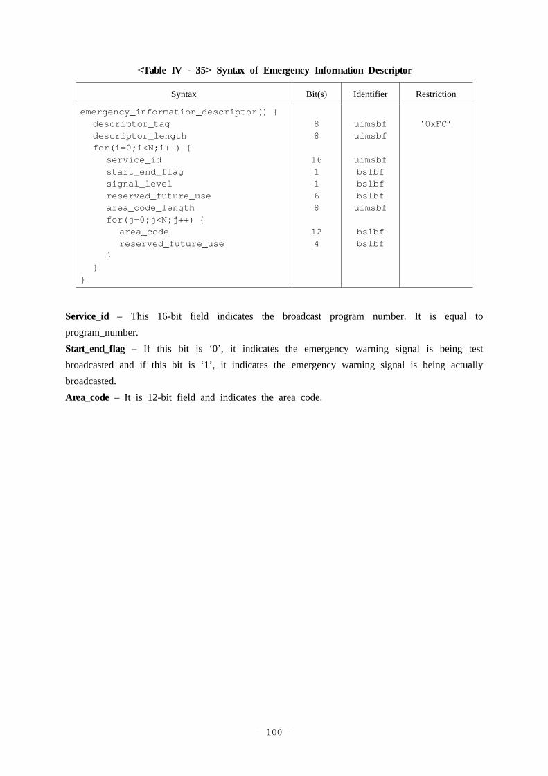
- 100 -
<Table IV - 35> Syntax of Emergency Information Descriptor
Syntax Bit(s) Identifier Restriction
emergency_information_descriptor() {descriptor_tagdescriptor_lengthfor(i=0;i<N;i++) {
service_idstart_end_flagsignal_levelreserved_future_usearea_code_lengthfor(j=0;j<N;j++) {
area_codereserved_future_use
}}
}
88
161168
124
uimsbfuimsbf
uimsbfbslbfbslbfbslbfuimsbf
bslbfbslbf
‘0xFC’
Service_id – This 16-bit field indicates the broadcast program number. It is equal to program_number.Start_end_flag – If this bit is ‘0’, it indicates the emergency warning signal is being test broadcasted and if this bit is ‘1’, it indicates the emergency warning signal is being actually broadcasted.Area_code – It is 12-bit field and indicates the area code.
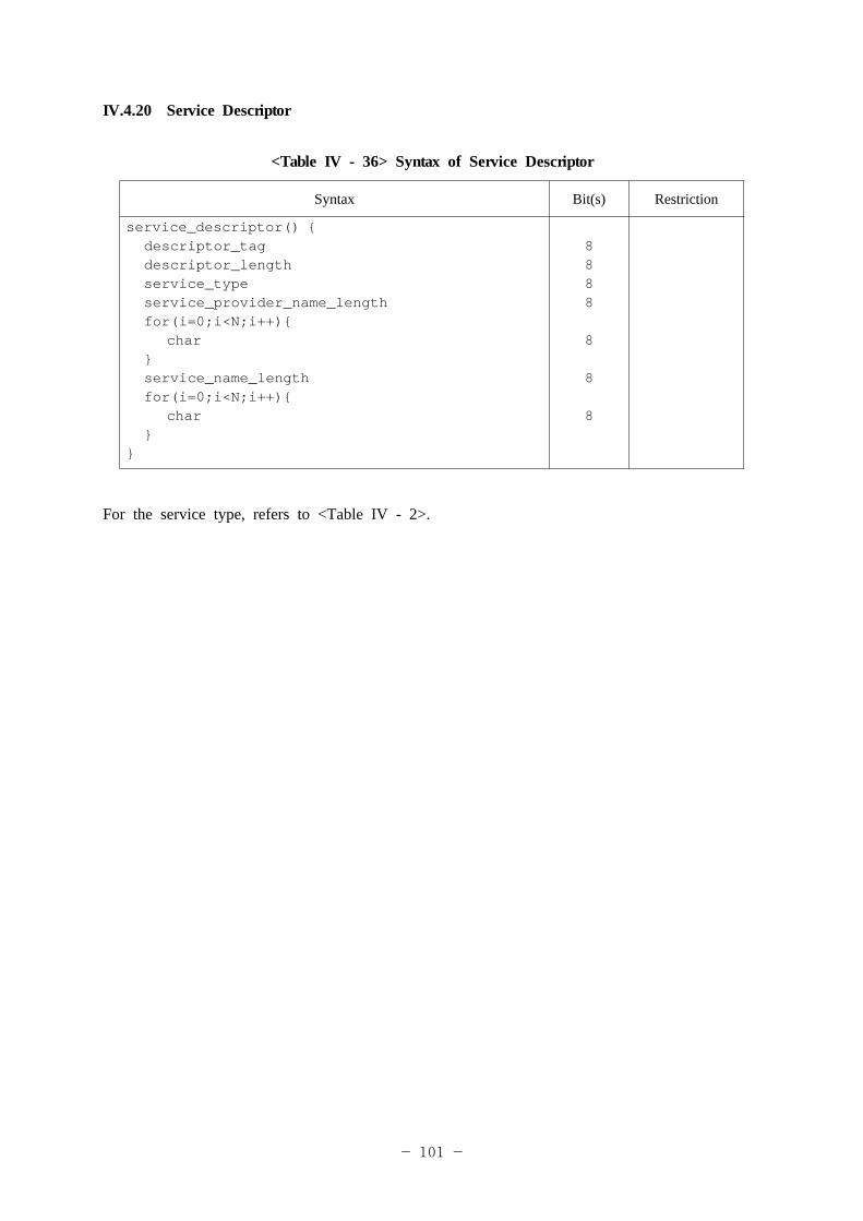
- 101 -
IV.4.20 Service Descriptor
<Table IV - 36> Syntax of Service Descriptor
Syntax Bit(s) Restriction
service_descriptor() {descriptor_tagdescriptor_lengthservice_typeservice_provider_name_lengthfor(i=0;i<N;i++){
char}service_name_lengthfor(i=0;i<N;i++){
char}
}
8888
8
8
8
For the service type, refers to <Table IV - 2>.
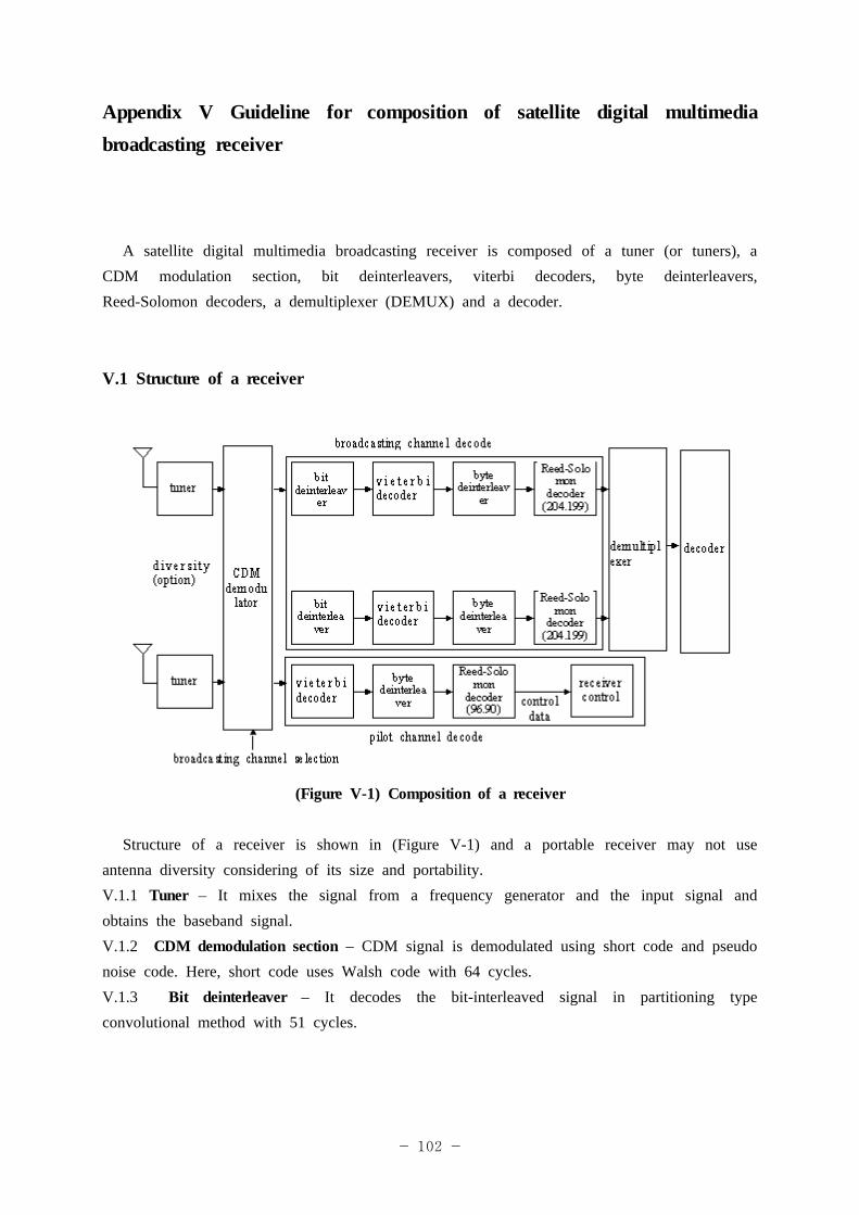
- 102 -
Appendix V Guideline for composition of satellite digital multimedia broadcasting receiver
A satellite digital multimedia broadcasting receiver is composed of a tuner (or tuners), a CDM modulation section, bit deinterleavers, viterbi decoders, byte deinterleavers, Reed-Solomon decoders, a demultiplexer (DEMUX) and a decoder.
V.1 Structure of a receiver
(Figure V-1) Composition of a receiver
Structure of a receiver is shown in (Figure V-1) and a portable receiver may not use antenna diversity considering of its size and portability. V.1.1 Tuner – It mixes the signal from a frequency generator and the input signal and obtains the baseband signal.V.1.2 CDM demodulation section – CDM signal is demodulated using short code and pseudo noise code. Here, short code uses Walsh code with 64 cycles. V.1.3 Bit deinterleaver – It decodes the bit-interleaved signal in partitioning type convolutional method with 51 cycles.
- 103 -
V.1.4 Viterbi decoder – It performs viterbi decoding with constraint length 7. V.1.5 Byte deinterleaver – It decodes the byte-interleaved signal in convolutional method with 12 cycles.V.1.6 Reed-Solomon decoder – It decodes the shortened Reed-Solomon (204, 188). Pilot channel performs Reed-Solomon (96, 80) decoding.V.1.7 Demultiplexer – It extracts each video/audio/data signal multiplexed in the MPEG-2 TS.V.1.8 Decoder – It decodes the elementary stream of the compressed video/audio.
V.2 Video signal processing method
V.2.1 Video decoding processing – It supports MPEG-4 Part10 Baseline [email protected] (ISO/IEC 14496-10) format or ITU-T Rec. H.264 format.V.2.2 Video resolution – It shall process at least QVGA (320*240) resolution or 15 fps.V.2.3 The number of sampling bits – It shall process 6 bits or 8 bits.V.2.4 In time of processing a video signal, audio signal in more than one channel shall be processed at the same time.
V.3 Audio Signal Processing MethodV.3.1 Audio decoding processing – It supports MPEG-2 AAC (ISO/IEC 13818-7) + SBR format.V.3.2 Sampling frequency - Maximum 48 kHz.V.3.3 The number of quantized bits – Maximum 24 bits.V.3.4 The number of decodable channels – Maximum two channels per one audio data channel.V.3.5 Audio decoding – It decodes audio mode including single mono, dual mono, stereo and etc.V.3.6 Identification and display of the audio mode – It shall identify and display the audio mode including single mono, dual mono, stereo and etc.
V.4 Minimum specification for a satellite digital multimedia broadcasting receiver The minimum specification for a satellite digital multimedia broadcasting receiver is as
follows.
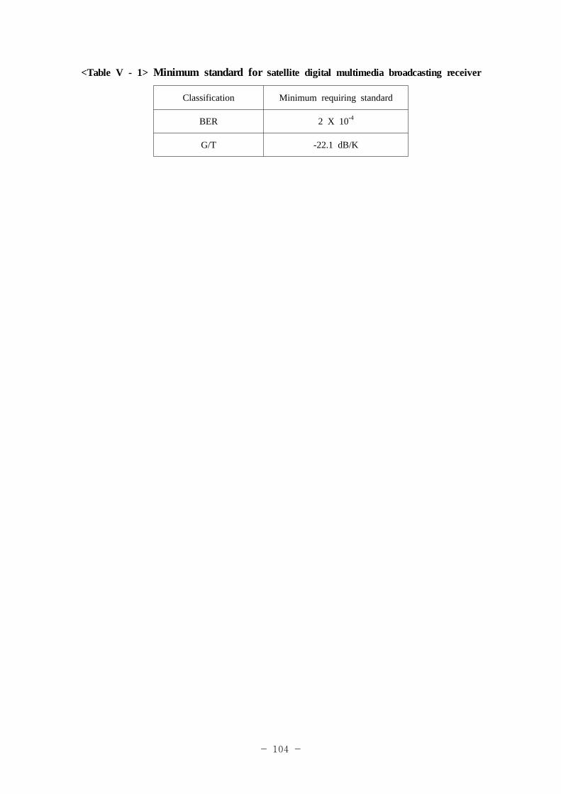
- 104 -
<Table V - 1> Minimum standard for satellite digital multimedia broadcasting receiver
Classification Minimum requiring standard
BER 2 X 10⁻⁴
G/T -22.1 dB/K
- 105 -
Appendix VI Abbreviation
VI.1 VI.2 VI.3 VI.4 VI.5 VI.6 VI.7 VI.8 VI.9 VI.10 VI.11 VI.12 VI.13 VI.14 VI.15 VI.16 VI.17 VI.18 VI.19 VI.20 VI.21 VI.20 VI.21 VI.22 VI.23 VI.24 VI.25
AAC Advanced Audio Coding.ARIB : Association of Radio Industries and BusinessesAVC Advanced Video Coding. BER : Bit Error RateBPSK : Binary Phase Shift KeyingCA : Conditional AccessCD : Compact DiskCDM : Code Division MultiplexingC/I : Carrier to InterferenceDMB Digital Multimedia Broadcasting ES : Elementary StreamLCD : Liquid Crystal DisplayMPEG Moving Picture Experts Group PN : Pseudo Noise PPM : Part(s) Per MillionQPSK : Quadrature Phase Shift Keying QVGA : Quarter Video Graphic ArraySI : Service Information SBR : Spectral Band ReplicationTS : Transport Stream VCD : Video Compact DiskTDM : Time Division MultiplexingRS : Reed SolomonEMM : Entitlement Management MessageECM : Entitlement Control MessagePID : Packet IdentifierDSM-CC : Digital Storage Media-Command and Control
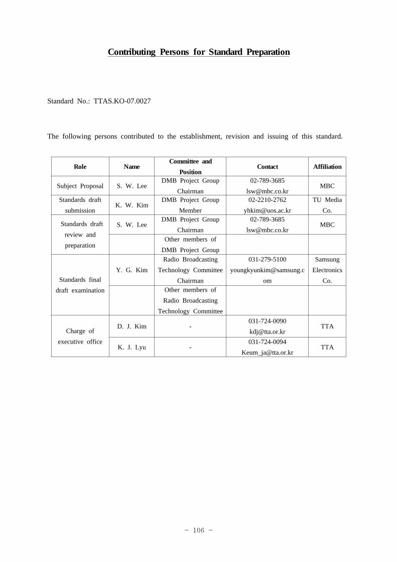
- 106 -
Contributing Persons for Standard Preparation
Standard No.: TTAS.KO-07.0027
The following persons contributed to the establishment, revision and issuing of this standard.
Role Name Committee and
PositionContact Affiliation
Subject Proposal S. W. LeeDMB Project Group
Chairman02-789-3685
Standards draft submission
K. W. KimDMB Project Group
Member02-2210-2762
[email protected] Media
Co.
Standards draft review and preparation
S. W. LeeDMB Project Group
Chairman02-789-3685
Other members of DMB Project Group
Standards final draft examination
Y. G. KimRadio Broadcasting
Technology Committee Chairman
om
Samsung Electronics
Co.Other members of Radio Broadcasting
Technology Committee
Charge of executive office
D. J. Kim [email protected]
TTA
K. J. Lyu -031-724-0094