Embed Size (px)
Citation preview
ELECTRICITY GENERATION AND DISTRIBUTION DEPARTMENT
STANDARD FOR STANDBY SUPPLY SOFT LOAD
TRANSFER SCHEME
CITY OF CAPE TOWN
DocumentTypeTitleResponsibleSectionTechnicalReference
Compiled by
Approved by
Supported
TECHNICAL STANDARD
Standby Supply Soft Load Transfer Scheme
Protection
Azeem Makaclam
r---....
(Signature) MJ�I � Azeem Makaclam
�
&
(Signature) !�
Dr Leslie Rencontre ,.
Director: Electricity Generation & Distribution
Edgar Capes Manager: Engineering
Marius Vcf} jler Westhuizen K-�uc.
Talu Tshivhase Manager: Electricity Supply
Hugo Mostert Manager: Enterprise Asset Management
Document: EEB 317 Revision: 1 Page: 1 of 13
ENERGY DIRECTORATE
DocumentEEB 317 Number
ReferenceCTES 074 Numbers
DocumentReview Status
Revision 1
Review Date 2 years aooroval
Date: ;;}_019 / 16 / a I
Date: 2.6 NOV 2019
from
1
2
3
4
5
6
Contents
OBJECTIVE
SCOPE
REFERENCE/ RELATED DOCUMENTS
DEFINITIONS, ABBREVIATIONS AND TERMS
INTRODUCTION
TECHNICAL DETAIL
6.1 TYPES OF LOAD TRANSFER SCHEMES
6.2 TECHNICAL REQUIREMENTS FOR THE IMPLEMENTATION OF SLT SCHEMES
6.2.1 Synchronisation
6.2.2 Unintentional islanded operation
6.2.3 Requirements for the utility network interface
7 APPLICATION PROCESS
7.1 INFORMATION REQUIRED FOR SLT APPLICATIONS
Document: EEB317 Revision: 1 Page: 2 of 13
8 PROTECTION STANDARDS APPLICABLE TO SLT SCHEMES
3
3
3
3
4
5
5
8
9
10
10
11
12
13
1 OBJECTIVE
Document: EEB 317 Revision: 1 Page: 3 of 13
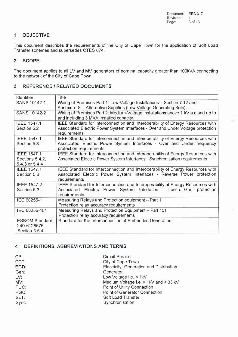
This document describes the requirements of the City of Cape Town for the application of Soft Load Transfer schemes and supersedes CTES 074.
2 SCOPE
The document applies to all LV and MV generators of nominal capacity greater than 1 00kVA connecting to the network of the City of Cape Town.
3 REFERENCE/ RELATED DOCUMENTS
Identifier Title SANS 10142-1 Wiring of Premises Part 1: Low-Voltage Installations - Section 7.12 and
Annexure S -Alternative Supplies (Low Voltage Generatinq Sets) SANS 10142-2 Wiring of Premises Part 2: Medium-Voltage Installations above 1 kV a.c and up to
and includinq 3 MVA installed capacity. IEEE 1547.1 IEEE Standard for Interconnection and Interoperability of Energy Resources with Section 5.2 Associated Electric Power System Interfaces - Over and Under Voltage protection
requirements IEEE 1547.1 IEEE Standard for Interconnection and Interoperability of Energy Resources with Section 5.3 Associated Electric Power System Interfaces - Over and Under frequency
protection requirements IEEE 1547.1 IEEE Standard for Interconnection and Interoperability of Energy Resources with Sections 5.4.2, Associated Electric Power System Interfaces - Synchronisation requirements 5.4.3 or 5.4.4 IEEE 1547.1 IEEE Standard for Interconnection and Interoperability of Energy Resources with Section 5.8 Associated Electric Power System Interfaces Reverse Power protection
requirements IEEE 1547.2 IEEE Standard for Interconnection and Interoperability of Energy Resources with Section 5.3 Associated Electric Power System Interfaces - Loss-of-Grid protection
requirements IEC 60255-1 Measuring Relays and Protection equipment - Part 1
Protection relay accuracy requirements
IEC 60255-151 Measuring Relays and Protection Equipment - Part 151 Protection relay accuracy requirements
ESKOM Standard Standard for the Interconnection of Embedded Generation 240-6128576Section 3.5.4
4 DEFINITIONS, ABBREVIATIONS AND TERMS
CB: CCT: EGD: Gen: LV: MV: PUC: PGC: SLT: Sync:
Circuit Breaker City of Cape Town Electricity, Generation and Distribution Generator Low Voltage i.e. < 1 kV Medium Voltage i.e. > 1 kV and < 33 kV Point of Utility Connection Point of Generator Connection Soft Load Transfer Synchronisation
5 INTRODUCTION
Document: EEB 317 Revision: 1 Page: 4 of 13
A SL T scheme is a stand-by generator system that operates in a 'make before break' mode with the utility supply so as to allow uninterrupted transfer of the customer's load from the utility grid supply to the backup generator supply and vice versa.
It is the intention of this document to describe the requirements of the CCT in this regard. This document will be subject to review following any changes to Statutory Legislation or National/International requirements.
The current status in the development of these requirements and standards permits the CCT to only consider applications from customers who have a three-phase connectiong with the CCT. The intention is to grant approval to SL T schemes to customers with critical loads that are vulnerable to supply interruptions or loadshedding.
Approval of the SL T scheme shall only be granted for generating plant that is designated for own use and not for commercial purposes. Each application shall be evaluated on its merits.
The CCT reserves the right to retrospectively require customers whom permission has been granted to connect a SL T scheme to the network, to comply with new or revised national standards when it is adopted. The customer shall be responsible for any costs associated with the changes required.
6 TECHNICAL DETAIL
6.1 Types of load transfer schemes
Document: EEB 317 Revision: 1 Page: 5 of 13
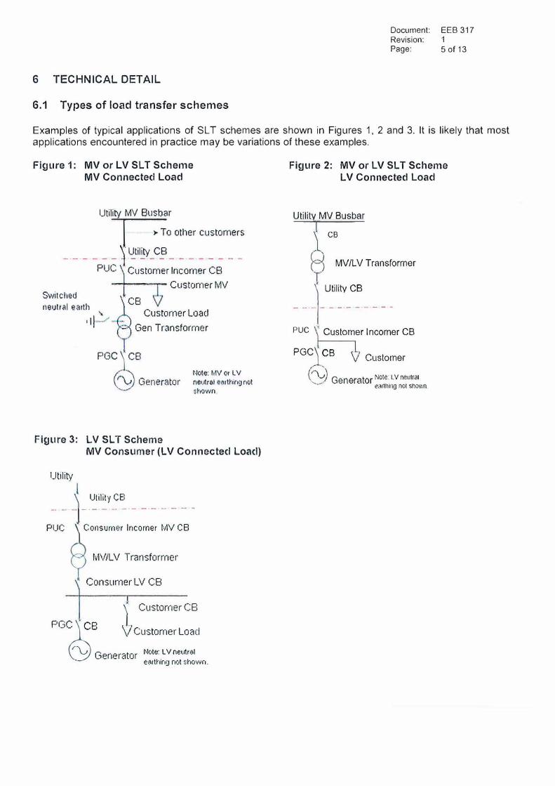
Examples of typical applications of SL T schemes are shown in Figures 1, 2 and 3. It is likely that most applications encountered in practice may be variations of these examples.
Figure 1: MV or LV SLT Scheme MV Connected Load
Utility MV 8usbar
�o other customers
\ Utility CB -·-·- - - - j - -·- -·- -·-·- - - - -PUC Customer Incomer CB
---........... Customer lvl\/ Switched
ne1Jll'�I earth CB
Custorner Loacl I II_...., Gen Transformer
PGC6)"'8 Note: MV or L V
rv Generator net�rc,I etir1hing not shown
Figure 3: LV SLT Scheme MV Consumer (LV Connected Load)
Utility
� Utility CB
-·- �,-·- - - - -·-·-·- - - -
PUC �Consumer Income, MV CB
� MV/LV Transformer
x Consurner LV CB
i Customer CB PGC�. CB Customer Loacl
Generator Note: L V ne�ltr$1e�uthing neit shown.
Figure 2: MV or LV SLT Scheme LV Connected Load
Utility MV Busbar
i ce
F� MV/LV Transformer' ) Utility CB
- -·-1- - -·-·-·- - - -
PUC x Customer Incomer CB
PGcB· CB \ Customer
(\-; Generator Note:. LV neutral-
eanh111g not shown.
Document: EEB 317 Revision: 1 Page: 6 of 13
In Figures 1, 2 and 3 the customer's generator is synchronised to the utility grid via the PGC. Once synchronised, the real and reactive power outputs of the generator are increased so as to reduce the real and reactive power imports to the customer's facility from the CCT distribution network.
In Figure 1 the customer facility includes loads or transformers supplied from MV. The automatic control system of the generator serves to minimise the power imports at the customer incomer or the CB at the PUC. Once the real and reactive power imports at the PUC have been reduced to near zero. The MV neutal earth switch Tsclosed and the CB at the PUC is opened, thereby islanding the customer's facility with the generator. The sequence of events for restoration of the grid supply includes, synchronising the customer network to the grid, closing the CB at the PUC, opening of the neutral earth switch, reduction of the generator's output to zero and disconnection of the generator via the PGC.
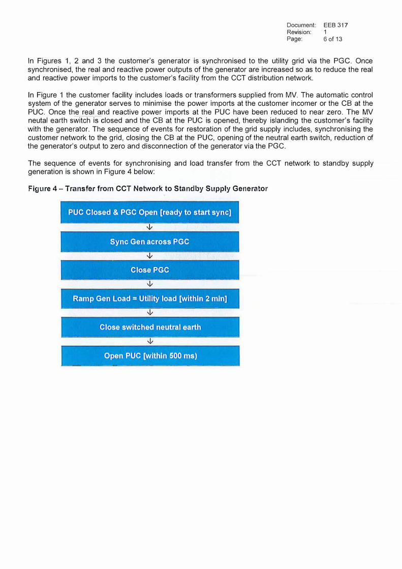
The sequence of events for synchronising and load transfer from the CCT network to standby supply generation is shown in Figure 4 below:
Figure 4 - Transfer from CCT Network to Standby Supply Generator
PUC Closed & PGC Open [ready to start sync] � ----- ---- - -- ------- ----- -- - ----
Sync Gen across PGC - - - - - -- - - - - -
Close PGC - - -- -------- ----- ----- ----- - - ---· -- -----
Ramp Gen Load= Utility load [within 2 min] - - - . - --- --------- -----
Close switched neutral earth ------ --- -----------------------
Open PUC [within 500 ms) - --- - - ------ ---- -- - --- ·- -- ·---- -- ----
Document: Revision: Page:
EEB 317 1 7 of 13
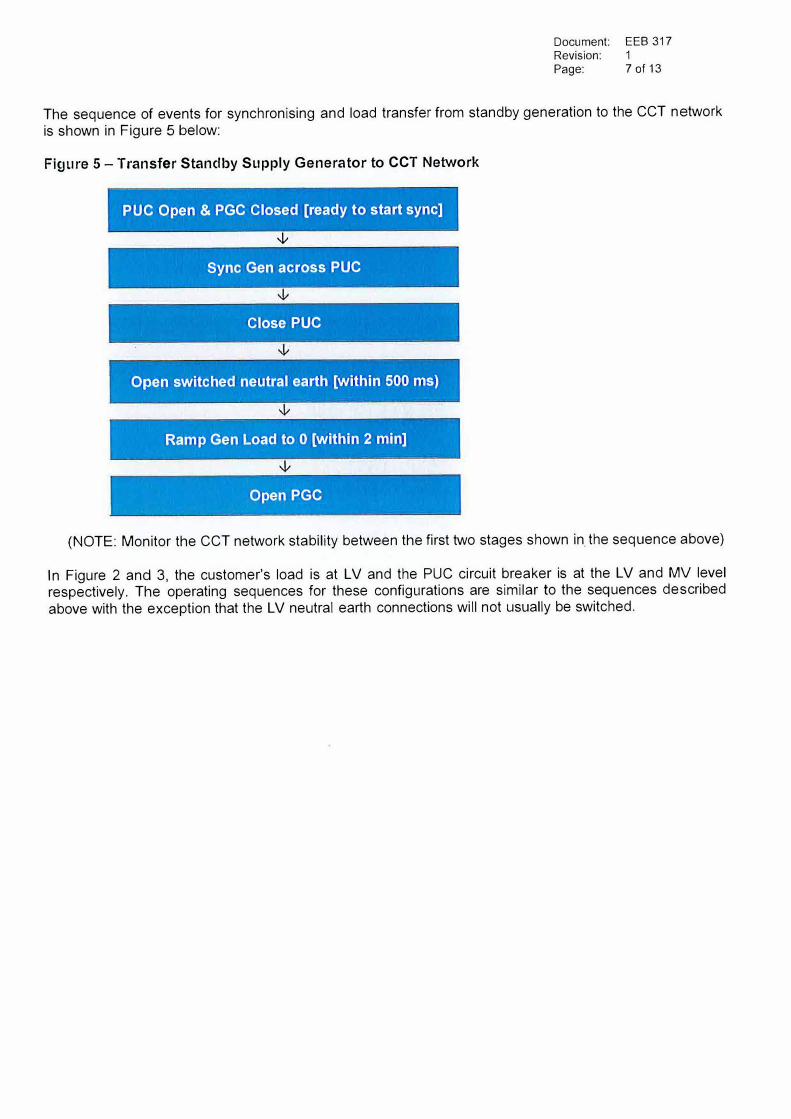
The sequence of events for synchronising and load transfer from standby generation to the CCT network is shown in Figure 5 below:
Figure 5 - Transfer Standby Supply Generator to CCT Network
PUC Open & PGC Closed [ready to start sync]
'V
Sync Gen across PUC
Close PUC
Open switched neutral earth [within 500 ms)
Ramp Gen Load to O [within 2 min]
Open PGC
(NOTE: Monitor the CCT network stability between the first two stages shown in. the sequence above)
In Figure 2 and 3, the customer's load is at LV and the PUC circuit breaker is at the LV and MV level respectively. The operating sequences for these configurations are similar to the sequences described above with the exception that the LV neutral earth connections will not usually be switched.
Document: EEB 317 Revision: 1 Page: 8 of 13
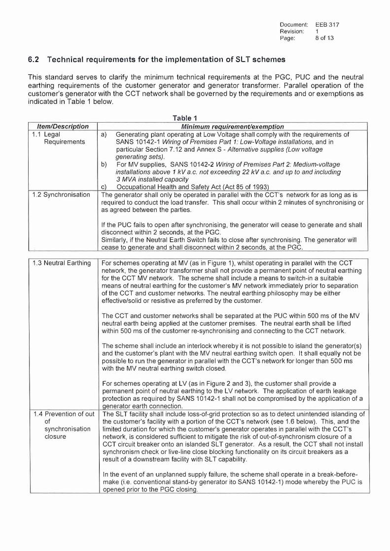
6.2 Technical requirements for the implementation of SL T schemes
This standard serves to clarify the minimum technical requirements at the PGC, PUC and the neutral earthing requirements of the customer generator and generator transformer. Parallel operation of the customer's generator with the CCT network shall be governed by the requirements and or exemptions as indicated in Table 1 below.
Table 1
Item/Description Minimum reauirementlexemption 1.1 Legal a) Generating plant operating at Low Voltage shall comply with the requirements of
Requirements SANS 10142-1 Wiring of Premises Part 1: Low-Voltage installations, and inparticular Section 7 .12 and Annex S - Alternative supplies (Low voltagegenerating sets).
b) For MV supplies, SANS 10142-2 Wiring of Premises Part 2: Medium-voltageinstallations above 1 kV a.c. not exceeding 22 kV a.c. and up to and including3 MVA installed capacity
c) Occupational Health and Safetv Act (Act 85 of 1993)1.2 Synchronisation The generator shall only be operated in parallel with the CCT's network for as long as is
required to conduct the load transfer. This shall occur within 2 minutes of synchronising oras agreed between the parties.
If the PUC fails to open after synchronising, the generator will cease to generate and shall disconnect within 2 seconds, at the PGC. Similarly, if the Neutral Earth Switch fails to close after synchronising. The generator will cease to qenerate and shall disconnect within 2 seconds, at the PGC.
1.3 Neutral Earthing For schemes operating at MV (as in Figure 1 ), whilst operating in parallel with the CCT network, the generator transformer shall not provide a permanent point of neutral earthing for the CCT MV network. The scheme shall include a means to switch-in a suitable means of neutral earthing for the customer's MV network immediately prior to separation of the CCT and customer networks. The neutral earthing philosophy may be either effective/solid or resistive as preferred by the customer.
1.4 Prevention of out of synchronisation closure
The CCT and customer networks shall be separated at the PUC within 500 ms of the MV neutral earth being applied at the customer premises. The neutral earth shall be lifted within 500 ms of the customer re-synchronising and connecting to the CCT network.
The scheme shall include an interlock whereby it is not possible to island the generator(s) and the customer's plant with the MV neutral earthing switch open. It shall equally not be possible to run the generator in parallel with the CCT's network for longer than 500 ms with the MV neutral earthing switch closed.
For schemes operating at LV (as in Figure 2 and 3), the customer shall provide a permanent point of neutral earthing to the L V network. The application of earth leakage protection as required by SANS 10142-1 shall not be compromised by the application of a qenerator earth connection. The SL T facility shall include loss-of-grid protection so as to detect unintended islanding of the customer's facility with a portion of the CCT's network (see 1.6 below). This, and the limited duration for which the customer's generator operates in parallel with the CCT's network, is considered sufficient to mitigate the risk of out-of-synchronism closure of a CCT circuit breaker onto an islanded SL T generator. As a result, the CCT shall not install synchronism check or live-line close blocking functionality on its circuit breakers as a result of a downstream facility with SL T capability.
In the event of an unplanned supply failure, the scheme shall operate in a break-beforemake (i.e. conventional stand-by generator ito SANS 10142-1) mode whereby the PUC is opened prior to the PGC closing.
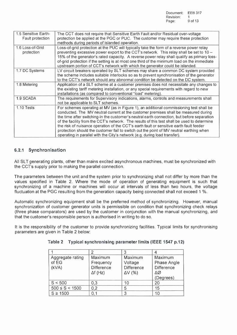
1.5 Sensitive Earth-Fault protection
1.6 Loss-of-Grid protection
1.7 DC Systems
1.8 Metering
1.9 SCADA
1.10 Tests
Document: EEB 317 Revision: 1 Page: 9 of 13
The CCT does not require that Sensitive Earth Fault and/or Residual over-voltage protection be applied at the PGC or PUC. The customer may require these protection methods durinq periods of islanded operation. Loss-of-grid protection at the PUC will typically take the form of a reverse power relay preventing excessive power export to the CCT's network. This relay shall be set to 10 -15% of the generator's rated capacity. A reverse power relay shall qualify as primary loss-of-grid protection if the setting is at most one third of the minimum load on the immediate upstream portion of CCT's network with which the qenerator could be islanded. LV circuit breakers operated by SLT schemes may share a common DC system provided the scheme includes suitable interlocks so as to prevent synchronisation of the generator to the CCT's network should any abnormal condition be detected on the DC svstem. Application of a SL T scheme at a customer premises does not necessitate any changes to the existing tariff metering installation, or any special requirements with regard to new installations (as compared to conventional "load" meterinq). The requirements for Supervisory indications, alarms, controls and measurements shall not be applicable to SL T schemes. For schemes operating at MV (as in Figure 1 ), an additional commissioning test shall be conducted. The MV neutral current at the customer premises shall be measured during the time after switching-in the customer's neutral earth connection, but before separation of the facility from the CCT's network. The results of this test shall be used to determine the risk of nuisance operation of the CCT's earth fault or sensitive earth fault feeder protection should the customer fail to switch out the point of MV neutral earthing when operatinq in parallel with the Citv's network (e.q, durinq load transfer).
6.2.1 Synchronisation
All SL T generating plants, other than mains excited asynchronous machines, must be synchronized with the CCT's supply prior to making the parallel connection.
The parameters between the unit and the system prior to synchronizing shall not differ by more than the values specified in Table 2. Where the mode of operation of generating equipment is such that synchronizing of a machine or machines will occur at intervals of less than two hours, the voltage fluctuation at the PGC resulting from the generation capacity being connected shall not exceed 1 %.
Automatic synchronizing equipment shall be the preferred method of synchronizing. However, manual synchronization of customer generator units is permissible on condition that synchronizing check relays (three phase comparators) are used by the customer in conjunction with the manual synchronizing, and that the customer's responsible person is authorised in writing to do so.
It is the responsibility of the customer to provide synchronizing facilities. Typical limits for synchronising parameters are given in Table 2 below:
Table 2 Typical synchronising parameter limits (IEEE 1547 p.12)
1 2 3 4 Aggregate rating Maximum Maximum Maximum of EG Frequency Voltage Phase Angle (kVA) Difference Difference Difference
Llf (Hz) LlV (%) L'.10
(Deqrees) S < 500 0,3 10 20
500:::; S < 1500 0,2 5 15
S 2: 1500 0, 1 3 10
6.2.2 Unintentional islanded operation
Document: EEB 317 Revision: 1 Page: 10of13
For unintentional islanding, where a generator is synchronised with the CCT's network at the time that an upstream CCT circuit breaker opens, severing the connection between the generator supply and the grid supply, the generator shall cease to generate within 2 seconds by opening the PUC customer incomer CB.
6.2.3 Requirements for the utility network interface
6.2.3.1 Fault infeed
Should the customer's generator(s) result in the increase of fault levels to such an extent that the
CCT's or the customer's plant at the PUC is placed at risk, the customer shall apply fault current limiting measures to ensure that the fault levels are maintained at acceptable levels. The fault limiting solution applied shall be presented to the CCT for acceptance prior to implementation.
6.2.3.2 Quality of supply
Voltage quality parameters, i.e. voltage regulation, unbalance, flicker and harmonic distortion, at the PUC and other customer points of supply, may not exceed the compatibility levels or limits as prescribed in NRS 048-2 due to operation of the installed generators. The rapid rate of voltage change limits, as set out in NRS 048-4, shall also not be exceeded.
6.2.3.3 Earthing
Adequate earthing of networks at other voltage levels within the customer's plant is the responsibility of the customer, and is not stipulated herein.
The CCT's networks may use effective, resistive or reactive earthing methods depending on the voltage level and local requirements. The magnitude of the possible earth fault current will depend on which of these methods is used. The customer's earthing arrangement must therefore be designed as follows:
a) In consultation with the CCT, such that the customer's system is compatible with the CCT'ssystem.
b) Such that the customer's plant safety is not compromised due to the above requirement.
The actual earthing arrangements will also be dependent on the number of machines in use and
the customer's system configuration and method of operation.
Earthing may be achieved by the use of a busbar earthing transformer (e.g.NEC/R), the use of the star point of the generator, or by earthing the star point of the generator transformer.
Care should be taken with multiple generator installations to avoid excessive circulating third harmonic currents. It may therefore be necessary to restrict the earthing to the star point of a single machine and provide automatic transfer facilities of the generator star point earth to another machine in the event of the selected machine being tripped. The use of suitable generator transformers with delta windings may provide a means of avoiding excessive circulating harmonic currents.
Document: EEB 317 Revision: 1 Page: 11 of 13
Where used, the winding configuration of the generator transformer (e.g. Delta-Star, Star-Delta etc.) shall be such that zero sequence currents on the CCT's network and the customer's systems are decoupled from one another.
Where transportable or mobile generating plant is used, it is essential that all earthing connections to the generator are effectively made prior to making off any phase connections or running the generator.
Under conditions of separation between the CCT's network and the customer's system, care must be taken to not run any part of any of the systems unearthed.
The customer shall also ensure that the customer MV generator earth grid is not connected to CCT network earth grid.
6.2.3.4 Isolating Transformer
No MV generators will be connected directly to the CCT network. This means an isolation transformer is required at the POC. An auto-transformer is not acceptable as it does not provide isolation. This is primarily to protect the CCT network from any disturbances created by the customer's generator(s).
For MV generators, the customer must ensure a switchable earth point is available on the CCT network side of the isolation transformer. This is to allow the detection of an earth fault during islanded operation.
A generator transformer will serve as an isolating transformer for MV generators.
7 APPLICATION PROCESS
Any customer wishing to operate or install a SL T scheme on the CCT's supplied network is required to apply to CCT for acceptance of the proposal. Customer may contact the EGO Department to obtain an application form which is also available on the EGO page of CCT website at:
http://www. capetown. gov .za/elecserviceforms
The contact details for EGO Customer Support Services East (Bloemhof), South (Wynberg) and North (CBD) are available on the application form.
Before SL T applications to connect in parallel with the CCT's electrical grid will be processed, the requirements of other departments of the CCT regarding the erection/installation of the proposed generators (e.g. diesel generator) must be met (e.g. Planning and Building Development Management and City Health Specialised Services). Statements of compliance and clearance by the respective departments must be reflected on the EGO application form for the connection of the standby supply (GEN/ELEC 1).
Customers who have already obtained permission from the other departments of the CCT to operate a low voltage standby supply who wish to install a SL T system, do not have to re-apply for the connection of standby supply. A new GEN/ELEC 1 application is required in writing, stating the reasons for the proposed SL T system as well as references to the existing and approved standby supply applications.
Applicant will be cost responsible for both in-house and outsourced engineering studies conducted as part of the application, should these be required. A quotation for such work will be provided beforehand, giving the applicant the opportunity to cancel or modify the application should it be required.
7.1 Information required for SL T applications
The following must be provided by the customer:
Document: Revision: Page:
EEB317 1 12 of 13
a) A single line diagram indicating the PUC and PGC as well as MV and L V switchgear,transformers, cables, earthing arrangements and the proposed connection of thesynchronisation/protection equipment.
b) A detailed technical specification of the proposed synchronisation equipment. This documentmust confirm that the synchronising relay(s) have been manufactured and tested in accordancewith international standards (i.e. type tested and comply with IEC 60255 and EN 50263).
c) The proposed synchronisation settings as referred to in Table 2 of this document.
d) The proposcid settings of the reverse power blocking/ loss of grid protection.
e) The written switching procedures during SL T operations.
f) Operations and Maintenance procedures and Installation Responsibilities after commissioning.
g) A certified copy of Certificate of Compliance in terms of OHS Act - Electrical InstallationRegulations
h) Standby supply generation compatibility with CCT network fault levels.
i) A commissioning check-list indicating that all SL T associated plant and protection functionshave been tested and commissioned in accordance with manufacturers standards and that thecorrect calculated relay settings have been applied.
j) A declaration by an ECSA registered Professional Engineer or Professional EngineeringTechnologist certifying that the SL T design and installation complies with this document andGEN/ELEC 1 - Application for the connection of a low voltage standby supply.
k) Standby supply generation decommissioning confirmation once applicable (GEN 2).
I) A Competent Person, in terms of the OHS Act, must be declared.
8 PROTECTION STANDARDS APPLICABLE TO SLT SCHEMES
Document: Revision: Page:
EEB 317 1 13 of 13
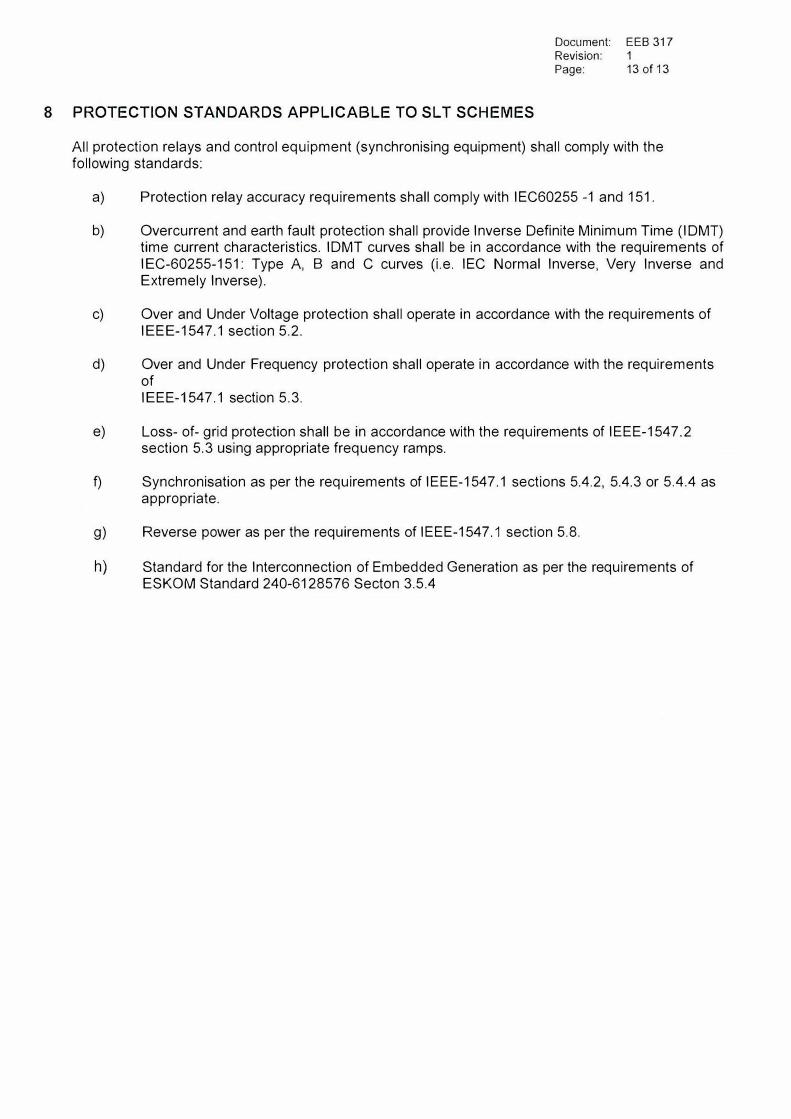
All protection relays and control equipment (synchronising equipment) shall comply with the following standards:
a) Protection relay accuracy requirements shall comply with IEC60255 -1 and 151.
b) Overcurrent and earth fault protection shall provide Inverse Definite Minimum Time (IDMT)time current characteristics. IDMT curves shall be in accordance with the requirements ofIEC-60255-151: Type A, B and C curves (i.e. IEC Normal Inverse, Very Inverse andExtremely Inverse).
c) Over and Under Voltage protection shall operate in accordance with the requirements ofIEEE-1547.1 section 5.2.
d) Over and Under Frequency protection shall operate in accordance with the requirementsofIEEE-1547.1 section 5.3.
e) Loss- of- grid protection shall be in accordance with the requirements of IEEE-1547.2section 5.3 using appropriate frequency ramps.
f) Synchronisation as per the requirements of IEEE-1547.1 sections 5.4.2, 5.4.3 or 5.4.4 asappropriate.
g) Reverse power as per the requirements of IEEE-1547.1 section 5.8.
h) Standard for the Interconnection of Embedded Generation as per the requirements ofESKOM Standard 240-6128576 Seeton 3.5.4
CITY OF CAPE TOWN
ISIXEKO SASEKAPA
STAD KAAPSTAD
ENERGY AND CLIMATE CHANGE DIRECTORATE
·.::rro-;)lo- ID 'l0l lM fMarius van der Weslhulzen
Manager: Infrastructure Operations
Date
To Attention
2019-10-10
THE HR BUSINESS PARTNER
Ms Maurietla Page
T: +27 21 444 8507 E: [email protected]
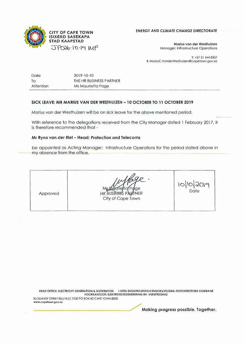
SICK LEAVE: MR MARIUS VAN DER WESTHUIZEN -10 OCTOBER TO 11 OCTOBER 2019
Marius van der Westhuizen will be on sick leave for the above mentioned period.
With reference to the delegations received from the City Manager dated 1 February 2017, it is therefore recommended that -
Mr Ryno van der Rlet - Head: Protection and Telecoms
be appointed as Acting Manager: Infrastructure Operations for the period stated above in my absence from the office.
Approved
�-
p ge HR NER
City of Cape Town
HEAD OFFICE: ELECTRICITY GENERATION & DISTRIBUTION l•OFISI ENGUNDLUNKULU ENGOKUVELISWA NOKUNIKEZELWA KOMBANE HOOFKANTOOR: ELEKTRISITEITSGENERERING EN -VERSPREIDING
BLOEMHOF STREET BELLVILLE 7530 PO BOX 82 CAPE TOWN 8000 www.copetown.gov.zo
Making progress possible. Together.