Embed Size (px)
Citation preview
Dieter Scholz:
Aircraft Systems
In: M.F. Platzer, B.N. Agrawal (Ed.):
Standard Handbook for Aerospace Engineers.
Pages 13-112. McGraw-Hill and SAE International, New York, 2018
ISBN: 978-1259585173
Hardcover: 1392 pages
1500 illustrations
Publisher:
McGraw-Hill Education
together with
SAE International
2nd Edition (2018-02-26)
Language: English
First Edition:
Publication date: 2002-10-10
Copyright: 2003
M. Davies (Ed.)
Title: The Standard Handbook for
Aeronautical and Astronautical Engineers
ISBN: 978-0071362290
Description
This resource presents theories and practices from more than 50 specialists in the
many sub-disciplines of aeronautical and astronautical engineering. The book
contains complete details on classic designs as well as the latest techniques,
materials, and processes used in aviation, defense, and space systems.
Table of Contents: Futures of aerospace --- Aircraft systems (SCHOLZ, Dieter) ---
Aerodynamics, aeroelasticity, and acoustics --- Aircraft performance --- Aircraft flight
mechanics, stability, and control --- Avionics and air traffic management systems ---
Aeronautical design --- Spacecraft design --- Astrodynamics --- Rockets and launch
vehicles --- Earth's environment and space --- Attitude dynamics and control.
URLs
McGraw-Hill:
https://www.mheducation.ca/professional/products/9781259585173
SAE International:
https://www.sae.org/publications/books/content/jp-mgh-001/
Amazon (preview):
https://www.amazon.com/dp/1259585174 (Hardcover)
https://www.amazon.de/dp/1259585174
https://www.amazon.com/dp/B079KMCWJC (Kindle)
https://www.amazon.de/dp/B079KMCWJC
WorldCat, the largest library catalog:
http://www.worldcat.org/oclc/1048241673
Access for university subscribers:
https://www.accessengineeringlibrary.com/browse/standard-handbook-for-
aerospace-engineers-second-edition
Standard Handbook for Aerospace
EngineersBrij N. Agrawal Editor
Max F. Platzer Editor
Second Edition
New York Chicago San Francisco Athens London Madrid
Mexico City Milan New Delhi Singapore Sydney Toronto
00_Agrawal_FM_pi-xxii.indd 1 04/01/18 6:21 PM
iii
McGraw-Hill Education books are available at special quantity discounts to use as premiums and sales promotions or for use in corporate training programs. To contact a representative, please visit the Contact Us page at www.mhprofessional.com.
Standard Handbook for Aerospace Engineers, Second Edition
Copyright © 2018, 2003 by McGraw-Hill Education. All rights reserved. Printed in the United States of America. Except as permitted under the United States Copyright Act of 1976, no part of this publication may be reproduced or distributed in any form or by any means, or stored in a data base or retrieval system, without the prior written permission of the publisher.
1 2 3 4 5 6 7 8 9 LCR 23 22 21 20 19 18
ISBN 978-1-259-58517-3 MHID 1-259-58517-4
The pages within this book were printed on acid-free paper.
The first edition of this book was titled The Standard Handbook for Aeronautical and Astronautical Engineers.
Information contained in this work has been obtained by McGraw-Hill Education from sources believed to be reliable. However, neither McGraw-Hill Education nor its authors guarantee the accuracy or completeness of any information published herein, and neither McGraw-Hill Education nor its authors shall be responsible for any errors, omissions, or damages arising out of use of this information. This work is published with the understanding that McGraw-Hill Education and its authors are supplying information but are not attempting to render engineering or other professional services. If such services are required, the assistance of an appropriate professional should be sought.
Sponsoring EditorRobert Argentieri
Editing SupervisorStephen M. Smith
Production SupervisorPamela A. Pelton
Acquisitions CoordinatorLauren Rogers
Project ManagersAnubhav Singh and Sonam Arora, Cenveo Publisher Services
Copy EditorSurendra Shivam,Cenveo Publisher Services
ProofreaderBarnali Ojha, Cenveo Publisher Services
Art Director, CoverJeff Weeks
CompositionCenveo Publisher Services
Library of Congress Control Number: 2017957635
00_Agrawal_FM_pi-xxii.indd 2 04/01/18 6:21 PM
xv
xiv C o n t e n t s
Contributors
Brij N . Agrawal Distinguished Professor, Department of Mechanical and Aerospace Engineering, Naval Postgraduate School, Monterey, California (Secs. 7, 11, 12)
Sachin Agrawal Senior Control Engineer, formerly at Space System Loral and Lockheed Martin, Palo Alto, California (Sec. 11)
D . N . Baker Laboratory for Atmospheric and Space Physics, University of Colorado, Boulder, Colorado (Sec. 10)
Eranga Batuwangala Researcher, Aerospace Engineering and Aviation Discipline, RMIT University, Bundoora, Victoria, Australia (Sec. 5)
Suraj Bijjahalli Researcher, Aerospace Engineering and Aviation Discipline, RMIT University, Bundoora, Victoria, Australia (Sec. 5)
Frederic Boniol Research Engineer, ONERA, France (Sec. 5)
Dominique Brière Head of Flight Control and Automatic Flight Control Systems Department, Airbus, France (Sec. 5)
Dennis M . Bushnell Chief Scientist, NASA Langley Research Center, Hampton, Virginia (Sec. 1)
J . P . Catani Head of Department, Power Supply and Electromagnetic Compatibility, Centre National d’Etudes Spatiales, France (Sec. 5)
Muguru S . Chandrasekhara Research Professor, Department of Mechanical and Aerospace Engineering, Naval Postgraduate School, Monterey, California (Sec. 3)
Florent Christophe Deputy Head, Department of Electromagnetism and Radar, ONERA, France (Sec. 5)
Jonathan Cooper Professor of Engineering, School of Engineering, University of Manchester, United Kingdom (Sec. 3)
Alan R . Crocker Senior System Engineer, NASA Ames Research Center, Moffett Field, California (Sec. 12)
M . Crokaert Doctor in Atomic Physics–Engineer, Centre National d’Etudes Spatiales, France (Sec. 5)
Atri Dutta Assistant Professor, Aerospace Engineering, Wichita State University, Wichita, Kansas (Sec. 8)
Peter Eckart Division of Astronautics, Technical University of Munich, Germany (Sec. 10)
John A . Ekaterinaris Distinguished Professor, Department of Aerospace Engineering, Embry-Riddle Aeronautical University, Daytona Beach, Florida (Sec. 3)
Jack Foisseau Head of Modelling and Requirement Engineering, ONERA, France (Sec. 5)
Anthony J . Gannon Associate Professor, Department of Mechanical and Aerospace Engineering, Naval Postgraduate School, Monterey, California (Sec. 3)
00_Agrawal_FM_pi-xxii.indd 15 04/01/18 6:21 PM
xvi C o n t r i b u t o r s C o n t r i b u t o r s xvii
Alessandro Gardi Research Officer, Aerospace Engineering and Aviation Discipline, RMIT University, Bundoora, Victoria, Australia (Sec. 5)
Guru P . Guruswamy Senior Scientist, NASA Ames Research Center, Moffett Field, California (Sec. 3)
Kenneth R . Hamm, Jr . NESC Chief Engineer, NASA Ames Research Center, Moffett Field, California (Sec. 11)
Thomas M . Hancock III Private Consultant, Systems Engineering and Flight Software Safety, Huntsville, Alabama (Sec. 11)
Rüdiger Jehn European Space Operation Center, Germany (Sec. 10)
Michael W . Jenkins Professor Emeritus of Aerospace Design, Georgia Institute of Technology, Atlanta, Georgia (Sec. 6)
Rohan Kapoor Researcher, Aerospace Engineering and Aviation Discipline, RMIT University, Bundoora, Victoria, Australia (Sec. 5)
Trevor Kistan Research and Technology Manager, THALES Australia, Melbourne, Victoria, Australia (Sec. 5)
Gary H . Kitmacher International Space Station Program, National Aeronautics and Space Administration, Johnson Space Center, Houston, Texas (Sec. 7)
G . Komatsu International Research School of Planetary Sciences, Università d’Annunzio, Italy (Sec. 10)
Yixiang Lim Researcher, Aerospace Engineering and Aviation Discipline, RMIT University, Bundoora, Victoria, Australia (Sec. 5)
Gerald Lo Formerly at INTELSAT, Washington, D.C. (Sec. 11)
Louis L . Maack Fellow, Lockheed Martin Space Systems, Sunnyvale, California (Sec. 7)
Jean-Claude Mollier Head of Department, Systemes Electronics Photoniques, SUPAERO, France (Sec. 5)
Roy Y . Myose Professor of Aerospace Engineering, Wichita State University, Wichita, Kansas (Sec. 8)
Andrew J . Niven Senior Lecturer, Department of Mechanical and Aeronautical Engineering, University of Limerick, Ireland (Sec. 3)
Tina L . Panontin Chief Engineer, NASA Ames Research Center, Moffett Field, California (Sec. 12)
J . P . Parmantier Doctor/Engineer in Electromagnetism, ONERA, France (Sec. 5)
Marc Pélegrin Docteur ès Sciences Automatics, FEDESPACE, France (Sec. 5)
Joseph N . Pelton Former Dean, International Space University, and Executive Board, International Association for the Advancement of Space Safety (Sec. 7)
Max F . Platzer Distinguished Professor Emeritus, Department of Mechanical and Aerospace Engineering, Naval Postgraduate School, Monterey, California (Sec. 3)
Sylvain Prudhomme Head of Identification and Control Research Group, ONERA, France (Sec. 5)
Jeffery J . Puschell Principal Engineering Fellow, Raytheon Company, El Segundo, California (Sec. 11)
Subramanian Ramasamy Research Officer, Aerospace Engineering and Aviation Discipline, RMIT University, Bundoora, Victoria, Australia (Sec. 5)
Michael J . Rycroft Cambridge Atmospheric, Environmental and Space Activities and Research, United Kingdom (Sec. 10)
Roberto Sabatini Professor of Aerospace Engineering and Aviation, RMIT University, Bundoora, Victoria, Australia (Sec. 5)
Abbas A . Salim Engineering Fellow/Principal Engineer (Retired), Lockheed Martin Space Systems, Denver, Colorado (Sec. 11)
00_Agrawal_FM_pi-xxii.indd 16 04/01/18 6:21 PM
xvi C o n t r i b u t o r s C o n t r i b u t o r s xvii
Nesrin Sarigul-Klijn Professor, Department of Mechanical and Aerospace Engineering, University of California, Davis, California (Sec. 3)
Dieter Scholz Professor, Aircraft Design and Systems, Hamburg University of Applied Sciences, Germany (Sec. 2)
Michael J . Sekerak Mission Systems Engineer, NASA Goddard Space Flight Center, Greenbelt, Maryland (Sec. 9)
Jerry Jon Sellers Senior Space Systems Engineer, Teaching Science and Technology, Inc., Manitou Springs, Colorado (Sec. 9)
Stevan M . Spremo Senior Systems Engineer, NASA Ames Research Center, Moffett Field, California (Sec. 12)
Constantinos Stavrinidis Former Head of Mechanical Engineering Department, ESTEC, European Space Agency, The Netherlands (Sec. 11)
Robert Stevens Director of Model-Based Systems Engineering Office, The Aerospace Corporation, El Segundo, California (Sec. 12)
Subchan Subchan Vice Rector of Academic Affairs, Kalimantan Institute of Technology, Malaysia (Sec. 4)
Douglas G . Thomson Chief Adviser of Studies, School of Engineering, University of Glasgow, United Kingdom (Sec. 4)
Trevor M . Young Associate Professor, Department of Mechanical and Aeronautical Engineering, University of Limerick, Ireland (Sec. 4)
Rafał Z .bikowski Professor of Control Engineering, Cranfield University, Cranfield, United Kingdom (Sec. 4)
00_Agrawal_FM_pi-xxii.indd 17 04/01/18 6:21 PM
xix
About the EditorsDr. Brij N. Agrawal is a Distinguished Professor in the Department of Mechanical and Aerospace Engineering and Director of the Spacecraft Research and Design Center at the Naval Postgraduate School (NPS). Prior to joining NPS in 1989, he worked for 20 years in the research, design, and development of communications satellites at COMSAT and INTELSAT. Dr. Agrawal is the author of Design of Geosynchronous Spacecraft. He is a Fellow of the American Institute of Aeronautics and Astronautics and a Member of the International Academy of Astronautics.
Dr. Max F. Platzer is a Distinguished Professor Emeritus in the Department of Mechanical and Aerospace Engineering at the Naval Postgraduate School (NPS). Prior to joining NPS in 1970, he was a member of the Saturn space launch vehicle development team at the NASA Marshall Space Flight Center and head of the Aeromechanics Research Group at the Lockheed Georgia Research Center. He is a Fellow of both the American Institute of Aeronautics and Astronautics and the American Society of Mechanical Engineers.
About SAE InternationalSAE International (sae.org) is a global association committed to being the ultimate knowledge source for the engineering profession. By uniting over 127,000 engineers and technical experts, we drive knowledge and expertise across a broad spectrum of industries. We act on two priorities: encouraging a lifetime of learning for mobility engineering professionals and setting the standards for industry engineering. We strive for a better world through the work of our charitable arm, the SAE Foundation, which helps fund programs like A World in Motion® and the Collegiate Design Series™.
00_Agrawal_FM_pi-xxii.indd 18 04/01/18 6:21 PM
xix
Preface to the Second Edition
In the 15 years since the publication of the first edition of this handbook, many new developments have occurred, especially in the astronautics field. We have included them in this second edition, which is divided into three major areas.In the first section the chief scientist of the NASA Langley Research Center presents his view of
the likely aerospace developments in the coming years. The subsequent five sections provide the reader with an update of the major developments in aeronautics. These include major advances in predicting and measuring very complex flow phenomena due to the rapid increases in computing power in recent years. Therefore, parts on computational fluid dynamics, modern flow measuring techniques, computational aeroelasticity, and computational acoustics have been added to the coverage of classical aerodynamic analysis methods retained from the first edition. Similarly, a part on optimal control theory was added to the coverage of aircraft performance, stability, and control in order to draw attention to the progress achieved in this field. This is followed by a major revision of avionics coverage because, here again, major advances have occurred. Also, in this section new parts on air traffic management have been added. Two sections retained with only minor changes cover aircraft systems and aircraft design.
The subsequent six sections provide the reader with an update of the major developments in astronautics. The sections titled Astrodynamics, Rockets and Launch Vehicles, and Earth’s Environment and Space have been retained from the first edition with an updating of the material. Three new sections titled Spacecraft Systems, Spacecraft Subsystems, and Spacecraft Design have been added. The Spacecraft Systems section covers satellite missions, test and product certification of space vehicles, space safety engineering and design, and spacecraft for human operation and habitation. The Spacecraft Subsystems section covers attitude dynamics and control, observation payloads, spacecraft structures, satellite electric power subsystems, systems engineering requirements, independent verification and validation, software safety for aerospace systems, thermal control, and communications. Spacecraft Design covers the spacecraft design process, a design example, concurrent engineering, and small spacecraft.
We would like to recognize the contributions of the editor of the first edition, Mark Davies. We are greatly indebted to the contributors of the new sections in the second edition for their efforts and cooperation and to the authors of the sections retained from the first edition for updating their work. Also, we express our special thanks to the Editorial Director—Engineering at McGraw-Hill, Robert Argentieri, and the Senior Project Manager at Cenveo Publisher Services, Sonam Arora, for their outstanding support during the preparation and production of this book. And then we are especially indebted to two wonderful ladies, our wives Shail Agrawal and Dorothea Platzer, who made it all possible through their love and understanding.
Brij N. AgrawalMax F. Platzer
Editors
00_Agrawal_FM_pi-xxii.indd 19 04/01/18 6:21 PM
xxi
Preface to the First Edition
T he Standard Handbook for Aeronautical and Astronautical Engineers represents the efforts of many people working toward the common goal of amalgamating aeronautical and astronautical engineering into a single handbook. This is the first publication of such a book.
A handbook on only astronautical was published by the same publishers in the early 1960s, which now represents a fascinating insight into the minds of those early pioneers.
The challenge to put the aeronautical and astronautical together was considerable. Although they overlap in so many ways, they also have many differences that needed to be addressed. The publisher’s brief was for a book that successfully brought about this combination and that would be of value to professional engineers and engineering students alike. It must, therefore, cover something of every aspect of the vast spectrum of knowledge and methods that is aerospace engineering. Working between the covers of a book that can be carried by an unaided individual, of average strength, has meant that much cannot be included.
At an early stage in the Handbook’s development, I decided that there would not be sufficient pages available to do justice to the military aspects of aerospace engineering. Consequently, the reader will not find many references to the military for the aeronautical and, similarly, for astronautical observation. Perhaps 75% of the book’s contents would be on most engineers’ list of essential engineering; the remaining 25% is there because of the section editors’ and my opinions and prejudices.
The Handbook opens with a look at what the future may hold for the development of aeronautical and space systems. This sets the scene for what is to follow. Before addressing these issues directly, there are five sections on basic engineering science and mathematics that are the foundation of aerospace operations and design. Applications have been excluded, for the most part, from these sections to emphasize their generality. In the specialist section, wherever possible, aeronautical and space issues have been addressed in the same section, as in Aerospace Structures (Section 9) and Avionics and Astrionics (11); elsewhere, they have been divided, as in Aeronautical Propulsion (7) and Rockets and Launch Vehicles (8). Subsystems for aircraft are covered in a single section (12), whereas for spacecraft, they are part of Section 15. Because aircraft design is more standardized and mature, it occupies its own section (13). Astrodynamics (14) and Spacecraft (15) are unique to space, whereas the discussions on safety (17) and maintenance (18) are unique to aircraft.
Due to its limited size, the book cannot give a definitive account of any specific area. Thus, experienced aerodynamicists may not find everything of interest in the aerodynamics section; nevertheless, they will find much of interest, for example, in the structures sections—the very structures that interact with the aerodynamic forces.
In this, the first edition, I feel that only the first stage in the journey to provide a comprehensive handbook has been made. Lionel Marks’ Standard Handbook for Mechanical Engineers, in print through many editions for almost a century, is a reference that has been invaluable to that discipline.
00_Agrawal_FM_pi-xxii.indd 21 04/01/18 6:21 PM
xxii P r e f a c e t o t h e F i r s t E d i t i o n
It is my hope that one day I will have made a similar contribution to aeronautical and astronautical engineering.
For the present, I thank all of those who have helped in this endeavor, beginning with my commissioning editor, Shelley Carr, with whom at times I have been in daily correspondence; she never wavered in her confidence and support for me, or if she did, I never knew. Then, I thank all of the section editors, the contributors, all of their colleagues and students who have helped, all of the institutes and companies that employ them, and my own institution, the University of Limerick, and my family: Judith, Elisabeth, and Helena.
Mark DaviesEditor
00_Agrawal_FM_pi-xxii.indd 22 04/01/18 6:21 PM
iii
Contents
Contributors . . . . . . . . . . . . . . . . . . . . . . . . . . . . . . . . . . . . . . . . . . . . . xvPreface to the Second Edition . . . . . . . . . . . . . . . . . . . . . . . . . . . . . . . xixPreface to the First Edition . . . . . . . . . . . . . . . . . . . . . . . . . . . . . . . . . xxi
Section 1 Futures of Aerospace . . . . . . . . . . . . . . . . . . . . . . . . . . . . . . 1 1.1 Potential Impacts of Global Technology and Resultant
Economic Context on Aerospace Going Forward . . . . . . . 1 1.2 Civilian Aeronautical Futures . . . . . . . . . . . . . . . . . . . . . . . . 2 1.3 Military Aeronautics Futures . . . . . . . . . . . . . . . . . . . . . . . . 4 1.4 Futures of Space Access . . . . . . . . . . . . . . . . . . . . . . . . . . . . . 7 1.5 Aerospace beyond LEO . . . . . . . . . . . . . . . . . . . . . . . . . . . . . 9Bibliography . . . . . . . . . . . . . . . . . . . . . . . . . . . . . . . . . . . . . . . . . . . . . 12
Section 2 Aircraft Systems . . . . . . . . . . . . . . . . . . . . . . . . . . . . . . . . . . 13 2.1 Introduction . . . . . . . . . . . . . . . . . . . . . . . . . . . . . . . . . . . . . . . 13 2.2 Air Conditioning (ATA 21) . . . . . . . . . . . . . . . . . . . . . . . . . . . 29 2.3 Electrical Power (ATA 24) . . . . . . . . . . . . . . . . . . . . . . . . . . . 37 2.4 Equipment/Furnishings (ATA 25) . . . . . . . . . . . . . . . . . . . . 45 2.5 Fire Protection (ATA 26) . . . . . . . . . . . . . . . . . . . . . . . . . . . . . 49 2.6 Flight Controls (ATA 27) . . . . . . . . . . . . . . . . . . . . . . . . . . . . 57 2.7 Fuel (ATA 28) . . . . . . . . . . . . . . . . . . . . . . . . . . . . . . . . . . . . . . 59 2.8 Hydraulic Power (ATA 29) . . . . . . . . . . . . . . . . . . . . . . . . . . 66 2.9 Ice and Rain Protection (ATA 30) . . . . . . . . . . . . . . . . . . . . . 73 2.10 Landing Gear (ATA 32) . . . . . . . . . . . . . . . . . . . . . . . . . . . . . . 85 2.11 Lights (ATA 33) . . . . . . . . . . . . . . . . . . . . . . . . . . . . . . . . . . . . 86 2.12 Oxygen (ATA 35) . . . . . . . . . . . . . . . . . . . . . . . . . . . . . . . . . . . 88 2.13 Pneumatic (ATA 36) . . . . . . . . . . . . . . . . . . . . . . . . . . . . . . . . 94 2.14 Water/Waste (ATA 38) . . . . . . . . . . . . . . . . . . . . . . . . . . . . . . 99 2.15 Airborne Auxiliary Power (ATA 49) . . . . . . . . . . . . . . . . . . . 102 2.16 Avionic Systems . . . . . . . . . . . . . . . . . . . . . . . . . . . . . . . . . . . . 104Acknowledgment . . . . . . . . . . . . . . . . . . . . . . . . . . . . . . . . . . . . . . . . . 106References . . . . . . . . . . . . . . . . . . . . . . . . . . . . . . . . . . . . . . . . . . . . . . . 106Further Reading . . . . . . . . . . . . . . . . . . . . . . . . . . . . . . . . . . . . . . . . . . 108
Section 3 Aerodynamics, Aeroelasticity, and Acoustics . . . . . . . . . . . . . 113 3.1 Introduction . . . . . . . . . . . . . . . . . . . . . . . . . . . . . . . . . . . . . . . 113
Part 1 The Physics of Drag and Lift Generation . . . . . . . . . . . . . . . . . . . . . . . . . . 114 3.2 Drag Generation . . . . . . . . . . . . . . . . . . . . . . . . . . . . . . . . . . . 115 3.3 Lift Generation on Airfoils in Two-Dimensional
Low-Speed Flow . . . . . . . . . . . . . . . . . . . . . . . . . . . . . . . . . . . 116
00_Agrawal_FM_pi-xxii.indd 3 04/01/18 6:21 PM
iv C o n t e n t s C o n t e n t s v
3.4 Lift Generation on Finite-Span Wings in Low-Speed Flow . . . 119 3.5 Lift Generation on Slender Wings . . . . . . . . . . . . . . . . . . . . 120 3.6 Lift Generation in Transonic and Supersonic Flight . . . . . 120 3.7 Lift Generation in Hypersonic Flight . . . . . . . . . . . . . . . . . . 120 3.8 Summary . . . . . . . . . . . . . . . . . . . . . . . . . . . . . . . . . . . . . . . . . 120References . . . . . . . . . . . . . . . . . . . . . . . . . . . . . . . . . . . . . . . . . . . . . . . 121
Part 2 Aerodynamic Analysis of Airfoils and Wings . . . . . . . . . . . . . . . . . . . . . . . . 122Notation . . . . . . . . . . . . . . . . . . . . . . . . . . . . . . . . . . . . . . . . . . . . . . . . . 122 3.9 Airfoil Geometric and Aerodynamic Definitions . . . . . . . . 124 3.10 Wing Geometric and Aerodynamic Definitions . . . . . . . . . 130 3.11 Fundamentals of Vector Fluid Dynamics . . . . . . . . . . . . . . 134 3.12 Fundamentals of Potential Flow . . . . . . . . . . . . . . . . . . . . . . 140 3.13 Elementary Boundary Layer Flow . . . . . . . . . . . . . . . . . . . . 149 3.14 Incompressible Flow Over Airfoils . . . . . . . . . . . . . . . . . . . . 156 3.15 Incompressible Flow Over Finite Wings . . . . . . . . . . . . . . . 176 3.16 Shock Wave Relationships . . . . . . . . . . . . . . . . . . . . . . . . . . . 187 3.17 Compressible Flow Over Airfoils . . . . . . . . . . . . . . . . . . . . . 195 3.18 Compressible Flow Over Finite Wings . . . . . . . . . . . . . . . . 204References . . . . . . . . . . . . . . . . . . . . . . . . . . . . . . . . . . . . . . . . . . . . . . . 213
Part 3 Aerodynamics of Low-Aspect-Ratio Wings and Bodies of Revolution . . . . . 215 3.19 Incompressible Inviscid Flow Over a Low-Aspect-Ratio
Wing at Zero Angle of Attack . . . . . . . . . . . . . . . . . . . . . . . . 215 3.20 Wave Drag . . . . . . . . . . . . . . . . . . . . . . . . . . . . . . . . . . . . . . . . 216 3.21 Equivalence Rule or Area Rule . . . . . . . . . . . . . . . . . . . . . . . 216 3.22 Bodies of Revolution at Small Angle of Attack . . . . . . . . . . 217 3.23 Cross-Flow Analysis for Slender Bodies of Revolution
at Small Angle of Attack . . . . . . . . . . . . . . . . . . . . . . . . . . . . . 218 3.24 Lift on a Slender Wing . . . . . . . . . . . . . . . . . . . . . . . . . . . . . . 220 3.25 Low-Aspect-Ratio Wing-Body Combinations
at Large Angle of Attack . . . . . . . . . . . . . . . . . . . . . . . . . . . . 221References . . . . . . . . . . . . . . . . . . . . . . . . . . . . . . . . . . . . . . . . . . . . . . . 222
Part 4 Computational Aerodynamics . . . . . . . . . . . . . . . . . . . . . . . . . . . . . . . . . . 224 3.26 Governing Equations . . . . . . . . . . . . . . . . . . . . . . . . . . . . . . . 224 3.27 Grid Generation . . . . . . . . . . . . . . . . . . . . . . . . . . . . . . . . . . . . 226 3.28 CFD Methods for the Compressible Navier–Stokes
Equations . . . . . . . . . . . . . . . . . . . . . . . . . . . . . . . . . . . . . . . . . 229References . . . . . . . . . . . . . . . . . . . . . . . . . . . . . . . . . . . . . . . . . . . . . . . 242
Part 5 Aeronautical Measurement Techniques . . . . . . . . . . . . . . . . . . . . . . . . . . . 244 3.29 General . . . . . . . . . . . . . . . . . . . . . . . . . . . . . . . . . . . . . . . . . . . 244 3.30 Major Components of a Wind Tunnel . . . . . . . . . . . . . . . . . 244 3.31 High-Speed Tunnels . . . . . . . . . . . . . . . . . . . . . . . . . . . . . . . . 245 3.32 Specialized Wind Tunnels . . . . . . . . . . . . . . . . . . . . . . . . . . . 246 3.33 Flow Measurement Techniques . . . . . . . . . . . . . . . . . . . . . . 246 3.34 Density-Based Optical Flow Field Measurement Methods . . . 253 3.35 Other Flow Field Measurement Methods . . . . . . . . . . . . . . 256References . . . . . . . . . . . . . . . . . . . . . . . . . . . . . . . . . . . . . . . . . . . . . . . 256
00_Agrawal_FM_pi-xxii.indd 4 04/01/18 6:21 PM
iv C o n t e n t s C o n t e n t s v
Part 6 Fast Response Pressure Probes . . . . . . . . . . . . . . . . . . . . . . . . . . . . . . . . 258 3.36 Probe Types and Ranges . . . . . . . . . . . . . . . . . . . . . . . . . . . . 258 3.37 Probe Mounting . . . . . . . . . . . . . . . . . . . . . . . . . . . . . . . . . . . . 259 3.38 Measuring Considerations . . . . . . . . . . . . . . . . . . . . . . . . . . . 260 3.39 Multisensor Probes . . . . . . . . . . . . . . . . . . . . . . . . . . . . . . . . . 260 3.40 Data Acquisition . . . . . . . . . . . . . . . . . . . . . . . . . . . . . . . . . . . 261 3.41 Postprocessing . . . . . . . . . . . . . . . . . . . . . . . . . . . . . . . . . . . . . 262References . . . . . . . . . . . . . . . . . . . . . . . . . . . . . . . . . . . . . . . . . . . . . . . 264
Part 7 Fundamentals of Aeroelasticity . . . . . . . . . . . . . . . . . . . . . . . . . . . . . . . . . 266 3.42 Aeroelasticity . . . . . . . . . . . . . . . . . . . . . . . . . . . . . . . . . . . . . . 266 3.43 Aircraft Airworthiness Certification . . . . . . . . . . . . . . . . . . . 270 3.44 Aeroelastic Design . . . . . . . . . . . . . . . . . . . . . . . . . . . . . . . . . . 272Further Reading . . . . . . . . . . . . . . . . . . . . . . . . . . . . . . . . . . . . . . . . . . 272
Part 8 Computational Aeroelasticity . . . . . . . . . . . . . . . . . . . . . . . . . . . . . . . . . . 273 3.45 Beginning of Transonic Small Perturbation Theory . . . . . . 273 3.46 Development of Euler and Navier–Stokes–Based
Computational Aeroelasticity Tools . . . . . . . . . . . . . . . . . . . 275 3.47 Computational Aeroelasticity in Rotorcraft . . . . . . . . . . . . 278 3.48 Impact of Parallel Computers and Development of
Three-Level Parallel Solvers . . . . . . . . . . . . . . . . . . . . . . . . . 279 3.49 Conclusion . . . . . . . . . . . . . . . . . . . . . . . . . . . . . . . . . . . . . . . . 281 3.50 Appendix: Domain Decomposition Approach . . . . . . . . . . 282References . . . . . . . . . . . . . . . . . . . . . . . . . . . . . . . . . . . . . . . . . . . . . . . 282
Part 9 Acoustics in Aerospace: Predictions, Measurements, and Mitigations of Aeroacoustics Noise . . . . . . . . . . . . . . . . . . . . . . . . . . . . . . . . . . . . . . . 286 3.51 Introduction . . . . . . . . . . . . . . . . . . . . . . . . . . . . . . . . . . . . . . . 286 3.52 Aeroacoustics Theoretical Background . . . . . . . . . . . . . . . . 286 3.53 Computational Aeroacoustics and Future Directions . . . . 290 3.54 Noise Measurements: Anechoic Chamber Experiments . . . . 292 3.55 Applications . . . . . . . . . . . . . . . . . . . . . . . . . . . . . . . . . . . . . . . 292Basic Terms . . . . . . . . . . . . . . . . . . . . . . . . . . . . . . . . . . . . . . . . . . . . . . 297References . . . . . . . . . . . . . . . . . . . . . . . . . . . . . . . . . . . . . . . . . . . . . . . 297
Section 4 Aircraft Performance, Stability, and Control . . . . . . . . . . . . . 299
Part 1 Aircraft Performance . . . . . . . . . . . . . . . . . . . . . . . . . . . . . . . . . . . . . . . . . 300Notation . . . . . . . . . . . . . . . . . . . . . . . . . . . . . . . . . . . . . . . . . . . . . . . . . 300 4.1 Standard Atmosphere and Height Measurement . . . . . . . 302 4.2 Airspeed and Airspeed Measurement . . . . . . . . . . . . . . . . . 313 4.3 Drag and Drag Power (Power Required) . . . . . . . . . . . . . . 316 4.4 Engine (Powerplant) Performance . . . . . . . . . . . . . . . . . . . . 321 4.5 Level Flight Performance . . . . . . . . . . . . . . . . . . . . . . . . . . . . 326 4.6 Climbing and Descending Flight . . . . . . . . . . . . . . . . . . . . . 330 4.7 Turning Performance . . . . . . . . . . . . . . . . . . . . . . . . . . . . . . . 337 4.8 Stall and Spin . . . . . . . . . . . . . . . . . . . . . . . . . . . . . . . . . . . . . . 339 4.9 Range and Endurance . . . . . . . . . . . . . . . . . . . . . . . . . . . . . . 340
00_Agrawal_FM_pi-xxii.indd 5 04/01/18 6:21 PM
vi C o n t e n t s C o n t e n t s vii
4.10 Takeoff and Landing Performance . . . . . . . . . . . . . . . . . . . . 346 4.11 Airplane Operations . . . . . . . . . . . . . . . . . . . . . . . . . . . . . . . . 352References . . . . . . . . . . . . . . . . . . . . . . . . . . . . . . . . . . . . . . . . . . . . . . . 356
Part 2 Aircraft Stability and Control . . . . . . . . . . . . . . . . . . . . . . . . . . . . . . . . . . . 358Notation . . . . . . . . . . . . . . . . . . . . . . . . . . . . . . . . . . . . . . . . . . . . . . . . . 358 4.12 Mathematical Modeling and Simulation of
Fixed-Wing Aircraft . . . . . . . . . . . . . . . . . . . . . . . . . . . . . . . . 359 4.13 Development of the Linearized Equations of Motion . . . . 367 4.14 Calculation of Aerodynamic Derivatives . . . . . . . . . . . . . . 375 4.15 Aircraft Dynamic Stability . . . . . . . . . . . . . . . . . . . . . . . . . . . 378 4.16 Aircraft Response to Controls and Atmospheric
Disturbances . . . . . . . . . . . . . . . . . . . . . . . . . . . . . . . . . . . . . . 382Further Reading . . . . . . . . . . . . . . . . . . . . . . . . . . . . . . . . . . . . . . . . . . 386
Part 3 Computational Optimal Control . . . . . . . . . . . . . . . . . . . . . . . . . . . . . . . . . 388 4.17 Optimal Control Problem . . . . . . . . . . . . . . . . . . . . . . . . . . . 388 4.18 Variational Approach to Optimal Control Problem
Solution . . . . . . . . . . . . . . . . . . . . . . . . . . . . . . . . . . . . . . . . . . . 390 4.19 Numerical Solution of the Optimal Control Problem . . . . 393 4.20 User Experience . . . . . . . . . . . . . . . . . . . . . . . . . . . . . . . . . . . . 398References . . . . . . . . . . . . . . . . . . . . . . . . . . . . . . . . . . . . . . . . . . . . . . . 408
Section 5 Avionics and Air Traffic Management Systems . . . . . . . . . . . . 411Acronyms . . . . . . . . . . . . . . . . . . . . . . . . . . . . . . . . . . . . . . . . . . . . . . . 411
Part 1 The Electromagnetic Spectrum . . . . . . . . . . . . . . . . . . . . . . . . . . . . . . . . . 420 5.1 Radio Waves in a Vacuum . . . . . . . . . . . . . . . . . . . . . . . . . . . 420 5.2 Antennas and Power Budget of a Radio Link . . . . . . . . . . . 421 5.3 Radio Wave Propagation in the Terrestrial
Environment . . . . . . . . . . . . . . . . . . . . . . . . . . . . . . . . . . . . . . 422 5.4 Electromagnetic Spectrum and Its Management . . . . . . . . 424References . . . . . . . . . . . . . . . . . . . . . . . . . . . . . . . . . . . . . . . . . . . . . . . 427
Part 2 Aircraft Environment . . . . . . . . . . . . . . . . . . . . . . . . . . . . . . . . . . . . . . . . . 428 5.5 Typical Flight Profile for Commercial Airplanes . . . . . . . . 428 5.6 The Atmosphere . . . . . . . . . . . . . . . . . . . . . . . . . . . . . . . . . . . 429 5.7 Other Atmospheric Hazards . . . . . . . . . . . . . . . . . . . . . . . . . 437 5.8 The Ionosphere . . . . . . . . . . . . . . . . . . . . . . . . . . . . . . . . . . . . 440References . . . . . . . . . . . . . . . . . . . . . . . . . . . . . . . . . . . . . . . . . . . . . . . 440
Part 3 Electromagnetic Compatibility . . . . . . . . . . . . . . . . . . . . . . . . . . . . . . . . . 441 5.9 Introduction . . . . . . . . . . . . . . . . . . . . . . . . . . . . . . . . . . . . . . . 441 5.10 Background of EM Coupling . . . . . . . . . . . . . . . . . . . . . . . . . 441 5.11 EM Environment and EMC Standards . . . . . . . . . . . . . . . . . 444 5.12 EMC Tools . . . . . . . . . . . . . . . . . . . . . . . . . . . . . . . . . . . . . . . . 446 5.13 Engineering Method . . . . . . . . . . . . . . . . . . . . . . . . . . . . . . . . 448 5.14 Conclusion . . . . . . . . . . . . . . . . . . . . . . . . . . . . . . . . . . . . . . . . 449References . . . . . . . . . . . . . . . . . . . . . . . . . . . . . . . . . . . . . . . . . . . . . . . 451
00_Agrawal_FM_pi-xxii.indd 6 04/01/18 6:21 PM
vi C o n t e n t s C o n t e n t s vii
Part 4 Introduction to Radar . . . . . . . . . . . . . . . . . . . . . . . . . . . . . . . . . . . . . . . . 452 5.15 Historical Background . . . . . . . . . . . . . . . . . . . . . . . . . . . . . . 452 5.16 Basic Principles . . . . . . . . . . . . . . . . . . . . . . . . . . . . . . . . . . . . 452 5.17 Trends in Radar Technology . . . . . . . . . . . . . . . . . . . . . . . . . 457 5.18 Radar Applications to Aeronautics . . . . . . . . . . . . . . . . . . . . 459 5.19 Overview of Military Requirements and
Specific Developments . . . . . . . . . . . . . . . . . . . . . . . . . . . . . . 461
Part 5 Avionics Electro-Optical Sensors . . . . . . . . . . . . . . . . . . . . . . . . . . . . . . . . 462 5.20 Introduction . . . . . . . . . . . . . . . . . . . . . . . . . . . . . . . . . . . . . . . 462 5.21 Fundamental Physical Laws . . . . . . . . . . . . . . . . . . . . . . . . . 462 5.22 IR Sensors . . . . . . . . . . . . . . . . . . . . . . . . . . . . . . . . . . . . . . . . . 464 5.23 Passive Optoelectronic Systems . . . . . . . . . . . . . . . . . . . . . . 465 5.24 NVIS Technology Overview . . . . . . . . . . . . . . . . . . . . . . . . . 470 5.25 NVIS Compatibility Issues . . . . . . . . . . . . . . . . . . . . . . . . . . 474 5.26 Airborne Lasers . . . . . . . . . . . . . . . . . . . . . . . . . . . . . . . . . . . . 474References . . . . . . . . . . . . . . . . . . . . . . . . . . . . . . . . . . . . . . . . . . . . . . . 480
Part 6 Optical Fibers . . . . . . . . . . . . . . . . . . . . . . . . . . . . . . . . . . . . . . . . . . . . . . 481 5.27 Optical Fiber Theory and Applications . . . . . . . . . . . . . . . . 481References . . . . . . . . . . . . . . . . . . . . . . . . . . . . . . . . . . . . . . . . . . . . . . . 488
Part 7 Aircraft Flight Control Systems . . . . . . . . . . . . . . . . . . . . . . . . . . . . . . . . . 489 5.28 Foreword . . . . . . . . . . . . . . . . . . . . . . . . . . . . . . . . . . . . . . . . . 489 5.29 Flight Control Objectives and Principles . . . . . . . . . . . . . . . 489 5.30 Flight Control Systems Design . . . . . . . . . . . . . . . . . . . . . . . 498 5.31 Airbus Fly-by-Wire: An Example of Modern
Flight Control . . . . . . . . . . . . . . . . . . . . . . . . . . . . . . . . . . . . . . 503 5.32 Some Control Challenges . . . . . . . . . . . . . . . . . . . . . . . . . . . . 514 5.33 Conclusion . . . . . . . . . . . . . . . . . . . . . . . . . . . . . . . . . . . . . . . . 516References . . . . . . . . . . . . . . . . . . . . . . . . . . . . . . . . . . . . . . . . . . . . . . . 516
Part 8 Modern Avionics Architectures . . . . . . . . . . . . . . . . . . . . . . . . . . . . . . . . . 518 5.34 Introduction to Avionics . . . . . . . . . . . . . . . . . . . . . . . . . . . . . 518 5.35 Requirements for Avionics . . . . . . . . . . . . . . . . . . . . . . . . . . . 520 5.36 Physical Architectures . . . . . . . . . . . . . . . . . . . . . . . . . . . . . . 520 5.37 Avionics Logical Architecture . . . . . . . . . . . . . . . . . . . . . . . . 524 5.38 Avionics Example: The Airbus A320 Flight
Control System . . . . . . . . . . . . . . . . . . . . . . . . . . . . . . . . . . . . 530Further Reading . . . . . . . . . . . . . . . . . . . . . . . . . . . . . . . . . . . . . . . . . . 532
Part 9 Aeronautical Communication Systems . . . . . . . . . . . . . . . . . . . . . . . . . . . 533 5.39 Introduction . . . . . . . . . . . . . . . . . . . . . . . . . . . . . . . . . . . . . . . 533 5.40 Evolutions . . . . . . . . . . . . . . . . . . . . . . . . . . . . . . . . . . . . . . . . 533 5.41 Aeronautical Radio Communication Types . . . . . . . . . . . . 534 5.42 Aeronautical Communication System Design . . . . . . . . . . 535 5.43 VHF Voice Communications . . . . . . . . . . . . . . . . . . . . . . . . . 544 5.44 VHF Datalink Communications . . . . . . . . . . . . . . . . . . . . . . 545 5.45 HF Communication System . . . . . . . . . . . . . . . . . . . . . . . . . 547 5.46 Satellite Communication System . . . . . . . . . . . . . . . . . . . . . 549
00_Agrawal_FM_pi-xxii.indd 7 04/01/18 6:21 PM
viii C o n t e n t s C o n t e n t s ix
5.47 Military Aeronautical Communications . . . . . . . . . . . . . . . 551 5.48 Future Trends . . . . . . . . . . . . . . . . . . . . . . . . . . . . . . . . . . . . . . 551References . . . . . . . . . . . . . . . . . . . . . . . . . . . . . . . . . . . . . . . . . . . . . . . 553
Part 10 Ground Radio Navigation Aids . . . . . . . . . . . . . . . . . . . . . . . . . . . . . . . . . . 554 5.49 Introduction . . . . . . . . . . . . . . . . . . . . . . . . . . . . . . . . . . . . . . . 554 5.50 Line-of-Sight Positioning . . . . . . . . . . . . . . . . . . . . . . . . . . . . 554 5.51 Calculation of Aircraft Position . . . . . . . . . . . . . . . . . . . . . . . 555 5.52 Air Navigation and Landing Aids . . . . . . . . . . . . . . . . . . . . 560References . . . . . . . . . . . . . . . . . . . . . . . . . . . . . . . . . . . . . . . . . . . . . . . 567
Part 11 Inertial Navigation Systems . . . . . . . . . . . . . . . . . . . . . . . . . . . . . . . . . . . . 568 5.53 Introduction . . . . . . . . . . . . . . . . . . . . . . . . . . . . . . . . . . . . . . . 568 5.54 Inertial Sensors . . . . . . . . . . . . . . . . . . . . . . . . . . . . . . . . . . . . 569References . . . . . . . . . . . . . . . . . . . . . . . . . . . . . . . . . . . . . . . . . . . . . . . 586
Part 12 Alternative Sensors and Multisensor Navigation Systems . . . . . . . . . . . . . 587 5.55 Introduction . . . . . . . . . . . . . . . . . . . . . . . . . . . . . . . . . . . . . . . 587 5.56 Vision-Based Navigation . . . . . . . . . . . . . . . . . . . . . . . . . . . . 587 5.57 Integrated Navigation Systems . . . . . . . . . . . . . . . . . . . . . . . 590References . . . . . . . . . . . . . . . . . . . . . . . . . . . . . . . . . . . . . . . . . . . . . . . 597
Part 13 Global Navigation Satellite Systems . . . . . . . . . . . . . . . . . . . . . . . . . . . . . 598 5.58 GNSS Segments . . . . . . . . . . . . . . . . . . . . . . . . . . . . . . . . . . . . 598 5.59 GNSS Observables . . . . . . . . . . . . . . . . . . . . . . . . . . . . . . . . . 599 5.60 GPS Error Sources . . . . . . . . . . . . . . . . . . . . . . . . . . . . . . . . . . 603 5.61 UERE Vector and DOP Factors . . . . . . . . . . . . . . . . . . . . . . . 607 5.62 GNSS Performance Requirements in Aviation . . . . . . . . . . 608 5.63 GNSS Augmentation Strategies in Aviation . . . . . . . . . . . . 610References . . . . . . . . . . . . . . . . . . . . . . . . . . . . . . . . . . . . . . . . . . . . . . . 615
Part 14 Airborne Separation Assurance and Collision Avoidance . . . . . . . . . . . . . . 617 5.64 Introduction . . . . . . . . . . . . . . . . . . . . . . . . . . . . . . . . . . . . . . . 617 5.65 Rules of AIR . . . . . . . . . . . . . . . . . . . . . . . . . . . . . . . . . . . . . . . 617 5.66 Airspace Categories and Classes . . . . . . . . . . . . . . . . . . . . . 617 5.67 Separation Standards . . . . . . . . . . . . . . . . . . . . . . . . . . . . . . . 618 5.68 Collision Detection and Avoidance . . . . . . . . . . . . . . . . . . . 619 5.69 Conflict Detection and Resolution Approaches . . . . . . . . . 623 5.70 SA&CA Technologies . . . . . . . . . . . . . . . . . . . . . . . . . . . . . . . 625 5.71 Conflict Resolution Heuristics . . . . . . . . . . . . . . . . . . . . . . . 628 5.72 Automatic Dependent Surveillance . . . . . . . . . . . . . . . . . . . 632 5.73 Multilateration Systems . . . . . . . . . . . . . . . . . . . . . . . . . . . . . 634References . . . . . . . . . . . . . . . . . . . . . . . . . . . . . . . . . . . . . . . . . . . . . . . 635
Part 15 Air Traffic Management Systems . . . . . . . . . . . . . . . . . . . . . . . . . . . . . . . . 637 5.74 General Layout of ATM Systems . . . . . . . . . . . . . . . . . . . . . 637 5.75 Fundamental ATM System Design Drivers . . . . . . . . . . . . 638 5.76 Airspace Structure . . . . . . . . . . . . . . . . . . . . . . . . . . . . . . . . . . 639 5.77 ATM Telecommunications Infrastructure . . . . . . . . . . . . . . 640
00_Agrawal_FM_pi-xxii.indd 8 04/01/18 6:21 PM
viii C o n t e n t s C o n t e n t s ix
5.78 ATM Surveillance Infrastructure . . . . . . . . . . . . . . . . . . . . . 642 5.79 Meteorological Services . . . . . . . . . . . . . . . . . . . . . . . . . . . . . 642 5.80 Trajectory Design . . . . . . . . . . . . . . . . . . . . . . . . . . . . . . . . . . . 646 5.81 CNS+A Evolutions . . . . . . . . . . . . . . . . . . . . . . . . . . . . . . . . . 647References . . . . . . . . . . . . . . . . . . . . . . . . . . . . . . . . . . . . . . . . . . . . . . . 649
Part 16 Aerospace Systems and Software Engineering . . . . . . . . . . . . . . . . . . . . . . 652 5.82 Introduction . . . . . . . . . . . . . . . . . . . . . . . . . . . . . . . . . . . . . . . 652 5.83 Software Life-Cycle Process . . . . . . . . . . . . . . . . . . . . . . . . . . 652 5.84 Software Requirements . . . . . . . . . . . . . . . . . . . . . . . . . . . . . 654 5.85 Software Design . . . . . . . . . . . . . . . . . . . . . . . . . . . . . . . . . . . 656 5.86 Aerospace Software Verification and Validation . . . . . . . . 657 5.87 Tools for Safety and Reliability Assessment . . . . . . . . . . . . 664 5.88 Certification Considerations for Aerospace Systems . . . . . 669References . . . . . . . . . . . . . . . . . . . . . . . . . . . . . . . . . . . . . . . . . . . . . . . 670
Part 17 Aviation Human Factors Engineering . . . . . . . . . . . . . . . . . . . . . . . . . . . . . 671 5.89 Human Performance Modeling . . . . . . . . . . . . . . . . . . . . . . 671 5.90 Human Factors Engineering Program . . . . . . . . . . . . . . . . . 674 5.91 Techniques for Task Analysis . . . . . . . . . . . . . . . . . . . . . . . . 676 5.92 Design Considerations . . . . . . . . . . . . . . . . . . . . . . . . . . . . . . 679 5.93 Design Evaluation . . . . . . . . . . . . . . . . . . . . . . . . . . . . . . . . . . 681References . . . . . . . . . . . . . . . . . . . . . . . . . . . . . . . . . . . . . . . . . . . . . . . 685
Section 6 Aeronautical Design . . . . . . . . . . . . . . . . . . . . . . . . . . . . . . . 687 6.1 Definitions . . . . . . . . . . . . . . . . . . . . . . . . . . . . . . . . . . . . . . . . 687 6.2 Introduction . . . . . . . . . . . . . . . . . . . . . . . . . . . . . . . . . . . . . . . 687 6.3 Overall Approach . . . . . . . . . . . . . . . . . . . . . . . . . . . . . . . . . . 687 6.4 Government Regulations . . . . . . . . . . . . . . . . . . . . . . . . . . . . 696 6.5 Conceptual Design . . . . . . . . . . . . . . . . . . . . . . . . . . . . . . . . . 703 6.6 Military Aircraft Design . . . . . . . . . . . . . . . . . . . . . . . . . . . . . 730 6.7 Commercial and Civil Aircraft Design . . . . . . . . . . . . . . . . . 731 6.8 Life Cycle Cost (LCC) . . . . . . . . . . . . . . . . . . . . . . . . . . . . . . . 733 6.9 Commercial Aircraft Operating Costs . . . . . . . . . . . . . . . . . 736 6.10 Unmanned Air Vehicles . . . . . . . . . . . . . . . . . . . . . . . . . . . . . 739 6.11 Lighter-Than-Air Vehicles (LTA) . . . . . . . . . . . . . . . . . . . . . . 743 6.12 V/STOL Air Vehicles . . . . . . . . . . . . . . . . . . . . . . . . . . . . . . . 745 6.13 Performance . . . . . . . . . . . . . . . . . . . . . . . . . . . . . . . . . . . . . . . 753References . . . . . . . . . . . . . . . . . . . . . . . . . . . . . . . . . . . . . . . . . . . . . . . 769Further Reading . . . . . . . . . . . . . . . . . . . . . . . . . . . . . . . . . . . . . . . . . . 769
Section 7 Spacecraft Systems . . . . . . . . . . . . . . . . . . . . . . . . . . . . . . . 771
Part 1 Space Missions . . . . . . . . . . . . . . . . . . . . . . . . . . . . . . . . . . . . . . . . . . . . 772 7.1 Introduction . . . . . . . . . . . . . . . . . . . . . . . . . . . . . . . . . . . . . . . 772 7.2 Orbits . . . . . . . . . . . . . . . . . . . . . . . . . . . . . . . . . . . . . . . . . . . . 776 7.3 Satellite Missions . . . . . . . . . . . . . . . . . . . . . . . . . . . . . . . . . . . 777
00_Agrawal_FM_pi-xxii.indd 9 04/01/18 6:21 PM
x C o n t e n t s C o n t e n t s xi
7.4 Launch Vehicles . . . . . . . . . . . . . . . . . . . . . . . . . . . . . . . . . . . . 801 7.5 Ground Segment . . . . . . . . . . . . . . . . . . . . . . . . . . . . . . . . . . . 803References . . . . . . . . . . . . . . . . . . . . . . . . . . . . . . . . . . . . . . . . . . . . . . . 805
Part 2 Test and Product Certification of Space Vehicles . . . . . . . . . . . . . . . . . . . . 806 7.6 Validation Basics . . . . . . . . . . . . . . . . . . . . . . . . . . . . . . . . . . . 806 7.7 Verification Basics . . . . . . . . . . . . . . . . . . . . . . . . . . . . . . . . . . 807 7.8 Requirements Development Basics . . . . . . . . . . . . . . . . . . . 808 7.9 Certification Requirements and Test Plan
Development . . . . . . . . . . . . . . . . . . . . . . . . . . . . . . . . . . . . . . 808 7.10 Verification Methods . . . . . . . . . . . . . . . . . . . . . . . . . . . . . . . . 809 7.11 Test Basics . . . . . . . . . . . . . . . . . . . . . . . . . . . . . . . . . . . . . . . . . 810 7.12 Compliance Documents . . . . . . . . . . . . . . . . . . . . . . . . . . . . . 811 7.13 TLYF Overview . . . . . . . . . . . . . . . . . . . . . . . . . . . . . . . . . . . . 816
Part 3 Space Safety Engineering and Design . . . . . . . . . . . . . . . . . . . . . . . . . . . . 820 7.14 Introduction . . . . . . . . . . . . . . . . . . . . . . . . . . . . . . . . . . . . . . . 820 7.15 Unmanned Space Systems Design and Engineering . . . . . 823 7.16 Crewed Space Systems Design and Engineering . . . . . . . . 823 7.17 Combustion and Materials Engineering and Safety . . . . . 826 7.18 Suborbital Flight Systems, Spaceplanes, Hypersonic
Transport, and New Uses of the “Protozone” or “Near Space” . . . . . . . . . . . . . . . . . . . . . . . . . . . . . . . . . . . . . . 827
7.19 Launch Site Design and Safety Standards . . . . . . . . . . . . . . 829 7.20 Licensing and Safety Controls and Management
for Various Types of Launcher Systems . . . . . . . . . . . . . . . . 829 7.21 Air and Space Traffic Control and Management . . . . . . . . 829 7.22 Atmospheric and Environmental Pollution . . . . . . . . . . . . 830 7.23 Orbital Debris Concerns and Tracking and
Sensor Systems . . . . . . . . . . . . . . . . . . . . . . . . . . . . . . . . . . . . 831 7.24 Cosmic Hazards and Planetary Defense and Safety . . . . . 832 7.25 Systems Engineering and Space Safety . . . . . . . . . . . . . . . . 833 7.26 Future Trends in Space Safety Engineering,
Design, and Study . . . . . . . . . . . . . . . . . . . . . . . . . . . . . . . . . . 835 7.27 Conclusions . . . . . . . . . . . . . . . . . . . . . . . . . . . . . . . . . . . . . . . 835References . . . . . . . . . . . . . . . . . . . . . . . . . . . . . . . . . . . . . . . . . . . . . . . 836
Part 4 Spacecraft for Human Operation and Habitation . . . . . . . . . . . . . . . . . . . . 838 7.28 Introduction . . . . . . . . . . . . . . . . . . . . . . . . . . . . . . . . . . . . . . . 838 7.29 Premium Placed on Mass and Volume . . . . . . . . . . . . . . . . 838 7.30 Common Attributes of Manned Spacecraft . . . . . . . . . . . . . 838 7.31 Optimization of Humans with Machines . . . . . . . . . . . . . . 844 7.32 Human Spacecraft Configuration . . . . . . . . . . . . . . . . . . . . . 844 7.33 Space Vehicle Architecture . . . . . . . . . . . . . . . . . . . . . . . . . . . 852 7.34 ISS Crew Compartment Design . . . . . . . . . . . . . . . . . . . . . . 855 7.35 Systems . . . . . . . . . . . . . . . . . . . . . . . . . . . . . . . . . . . . . . . . . . . 858 7.36 Summary . . . . . . . . . . . . . . . . . . . . . . . . . . . . . . . . . . . . . . . . . 879References . . . . . . . . . . . . . . . . . . . . . . . . . . . . . . . . . . . . . . . . . . . . . . . 880
00_Agrawal_FM_pi-xxii.indd 10 04/01/18 6:21 PM
x C o n t e n t s C o n t e n t s xi
Section 8 Astrodynamics . . . . . . . . . . . . . . . . . . . . . . . . . . . . . . . . . . . 881Notation . . . . . . . . . . . . . . . . . . . . . . . . . . . . . . . . . . . . . . . . . . . . . . . . . 881 8.1 Orbital Mechanics . . . . . . . . . . . . . . . . . . . . . . . . . . . . . . . . . . 882 8.2 Orbital Maneuvers . . . . . . . . . . . . . . . . . . . . . . . . . . . . . . . . . 893 8.3 Earth Orbiting Satellites . . . . . . . . . . . . . . . . . . . . . . . . . . . . . 903 8.4 Interplanetary Missions . . . . . . . . . . . . . . . . . . . . . . . . . . . . . 916References . . . . . . . . . . . . . . . . . . . . . . . . . . . . . . . . . . . . . . . . . . . . . . . 928
Section 9 Rockets and Launch Vehicles . . . . . . . . . . . . . . . . . . . . . . . . 929 9.1 Rocket Science . . . . . . . . . . . . . . . . . . . . . . . . . . . . . . . . . . . . . 929 9.2 Propulsion Systems . . . . . . . . . . . . . . . . . . . . . . . . . . . . . . . . . 949 9.3 Launch Vehicles . . . . . . . . . . . . . . . . . . . . . . . . . . . . . . . . . . . . 970References . . . . . . . . . . . . . . . . . . . . . . . . . . . . . . . . . . . . . . . . . . . . . . . 976
Section 10 Earth’s Environment and Space . . . . . . . . . . . . . . . . . . . . . . 977
Part 1 The Earth and Its Atmosphere . . . . . . . . . . . . . . . . . . . . . . . . . . . . . . . . . . 978 10.1 The Earth in Space . . . . . . . . . . . . . . . . . . . . . . . . . . . . . . . . . . 978 10.2 Properties of the Earth’s Atmosphere . . . . . . . . . . . . . . . . . 978 10.3 How the Earth’s Atmosphere Works . . . . . . . . . . . . . . . . . . 980 10.4 Atmospheric Dynamics and Atmospheric
Models . . . . . . . . . . . . . . . . . . . . . . . . . . . . . . . . . . . . . . . . . . . 983 10.5 Electrical Phenomena in the Atmosphere . . . . . . . . . . . . . . 986References . . . . . . . . . . . . . . . . . . . . . . . . . . . . . . . . . . . . . . . . . . . . . . . 987
Part 2 The Near-Earth Space Environment . . . . . . . . . . . . . . . . . . . . . . . . . . . . . . 988 10.6 Background . . . . . . . . . . . . . . . . . . . . . . . . . . . . . . . . . . . . . . . 988 10.7 The Plasma Environment . . . . . . . . . . . . . . . . . . . . . . . . . . . . 989 10.8 The Neutral Gas Environment . . . . . . . . . . . . . . . . . . . . . . . 992 10.9 The Vacuum Environment . . . . . . . . . . . . . . . . . . . . . . . . . . . 99310.10 The Radiation Environment . . . . . . . . . . . . . . . . . . . . . . . . . 99310.11 The Micrometeoroid and Space Debris
Environment . . . . . . . . . . . . . . . . . . . . . . . . . . . . . . . . . . . . . . 996References . . . . . . . . . . . . . . . . . . . . . . . . . . . . . . . . . . . . . . . . . . . . . . . 996
Part 3 The Solar System . . . . . . . . . . . . . . . . . . . . . . . . . . . . . . . . . . . . . . . . . . . 99710.12 Physical Properties of the Planets . . . . . . . . . . . . . . . . . . . . . 99710.13 Space Age Discoveries . . . . . . . . . . . . . . . . . . . . . . . . . . . . . . 997References . . . . . . . . . . . . . . . . . . . . . . . . . . . . . . . . . . . . . . . . . . . . . . . 1003
Part 4 The Moon . . . . . . . . . . . . . . . . . . . . . . . . . . . . . . . . . . . . . . . . . . . . . . . . . 100410.14 Origin of the Moon . . . . . . . . . . . . . . . . . . . . . . . . . . . . . . . . . 100410.15 Orbital Parameters . . . . . . . . . . . . . . . . . . . . . . . . . . . . . . . . . 100510.16 Lunar Geography . . . . . . . . . . . . . . . . . . . . . . . . . . . . . . . . . . 100610.17 Lunar Geology . . . . . . . . . . . . . . . . . . . . . . . . . . . . . . . . . . . . . 100710.18 Physical Surface Properties . . . . . . . . . . . . . . . . . . . . . . . . . . 101010.19 Lunar Surface Environment . . . . . . . . . . . . . . . . . . . . . . . . . 1016References . . . . . . . . . . . . . . . . . . . . . . . . . . . . . . . . . . . . . . . . . . . . . . . 1020
00_Agrawal_FM_pi-xxii.indd 11 04/01/18 6:21 PM
xii C o n t e n t s C o n t e n t s xiii
Part 5 Mars . . . . . . . . . . . . . . . . . . . . . . . . . . . . . . . . . . . . . . . . . . . . . . . . . . . . . 102110.20 Orbital Characteristics . . . . . . . . . . . . . . . . . . . . . . . . . . . . . . 102110.21 Solid Geophysical Properties and Interiors . . . . . . . . . . . . . 102110.22 Surface and Subsurface . . . . . . . . . . . . . . . . . . . . . . . . . . . . . 102310.23 Atmosphere . . . . . . . . . . . . . . . . . . . . . . . . . . . . . . . . . . . . . . . 102710.24 Satellites . . . . . . . . . . . . . . . . . . . . . . . . . . . . . . . . . . . . . . . . . . 102910.25 Search for Life on Mars . . . . . . . . . . . . . . . . . . . . . . . . . . . . . 102910.26 Exploration . . . . . . . . . . . . . . . . . . . . . . . . . . . . . . . . . . . . . . . . 1030References . . . . . . . . . . . . . . . . . . . . . . . . . . . . . . . . . . . . . . . . . . . . . . . 1031
Part 6 The Sun–Earth Connection . . . . . . . . . . . . . . . . . . . . . . . . . . . . . . . . . . . . 103310.27 Introduction . . . . . . . . . . . . . . . . . . . . . . . . . . . . . . . . . . . . . . . 103310.28 The Sun and the Heliosphere . . . . . . . . . . . . . . . . . . . . . . . . 103310.29 Structure and Dynamics of the Magnetospheric
System . . . . . . . . . . . . . . . . . . . . . . . . . . . . . . . . . . . . . . . . . . . . 103610.30 The Solar–Terrestrial Energy Chain . . . . . . . . . . . . . . . . . . . 103710.31 Dynamics of the Magnetosphere-Ionosphere-
Atmosphere System . . . . . . . . . . . . . . . . . . . . . . . . . . . . . . . . 103810.32 Importance of Atmospheric Coupling . . . . . . . . . . . . . . . . . 104210.33 Sun–Earth Connections and Human Technology . . . . . . . 104310.34 Summary . . . . . . . . . . . . . . . . . . . . . . . . . . . . . . . . . . . . . . . . . 1044Further Reading . . . . . . . . . . . . . . . . . . . . . . . . . . . . . . . . . . . . . . . . . . 1045
Part 7 Space Debris . . . . . . . . . . . . . . . . . . . . . . . . . . . . . . . . . . . . . . . . . . . . . . 104610.35 Introduction . . . . . . . . . . . . . . . . . . . . . . . . . . . . . . . . . . . . . . . 104610.36 Spatial Distribution of Space Debris . . . . . . . . . . . . . . . . . . 104810.37 The Collision Risk . . . . . . . . . . . . . . . . . . . . . . . . . . . . . . . . . . 105010.38 The Geostationary Orbit . . . . . . . . . . . . . . . . . . . . . . . . . . . . . 105210.39 Long-Term Evolution of the Space Debris Environment
and Mitigation Measures . . . . . . . . . . . . . . . . . . . . . . . . . . . . 1052References . . . . . . . . . . . . . . . . . . . . . . . . . . . . . . . . . . . . . . . . . . . . . . . 1054Further Reading . . . . . . . . . . . . . . . . . . . . . . . . . . . . . . . . . . . . . . . . . . 1054
Section 11 Spacecraft Subsystems . . . . . . . . . . . . . . . . . . . . . . . . . . . . 1055
Part 1 Attitude Dynamics and Control . . . . . . . . . . . . . . . . . . . . . . . . . . . . . . . . . 1056 11.1 Introduction . . . . . . . . . . . . . . . . . . . . . . . . . . . . . . . . . . . . . . . 1056 11.2 Rigid-Body Dynamics . . . . . . . . . . . . . . . . . . . . . . . . . . . . . . . 1056 11.3 Orientation Kinematics . . . . . . . . . . . . . . . . . . . . . . . . . . . . . . 1063 11.4 Attitude Stabilization . . . . . . . . . . . . . . . . . . . . . . . . . . . . . . . 1071 11.5 Spin Stabilization of an Energy-Dissipating Spacecraft . . . 1075 11.6 Three-Axis Stabilization . . . . . . . . . . . . . . . . . . . . . . . . . . . . . 1076 11.7 Disturbance Torques . . . . . . . . . . . . . . . . . . . . . . . . . . . . . . . . 1077 11.8 Spacecraft with a Fixed Momentum Wheel and Thrusters . . . 1083 11.9 Three-Axis Reaction Wheel System . . . . . . . . . . . . . . . . . . . 109111.10 Control Moment Gyroscope . . . . . . . . . . . . . . . . . . . . . . . . . 109511.11 Effects of Structural Flexibility . . . . . . . . . . . . . . . . . . . . . . . 1098
00_Agrawal_FM_pi-xxii.indd 12 04/01/18 6:21 PM
xii C o n t e n t s C o n t e n t s xiii
11.12 Attitude Determination . . . . . . . . . . . . . . . . . . . . . . . . . . . . . 1103References . . . . . . . . . . . . . . . . . . . . . . . . . . . . . . . . . . . . . . . . . . . . . . . 1106
Part 2 Observation Payloads . . . . . . . . . . . . . . . . . . . . . . . . . . . . . . . . . . . . . . . . 110811.13 Overview . . . . . . . . . . . . . . . . . . . . . . . . . . . . . . . . . . . . . . . . . 110811.14 Observational Payload Types . . . . . . . . . . . . . . . . . . . . . . . . 110911.15 Observational Payload Performance Figures of Merit . . . 1123References . . . . . . . . . . . . . . . . . . . . . . . . . . . . . . . . . . . . . . . . . . . . . . . 1126
Part 3 Spacecraft Structures . . . . . . . . . . . . . . . . . . . . . . . . . . . . . . . . . . . . . . . 112811.16 Role of Spacecraft Structures and Various Interfaces . . . . . 112811.17 Mechanical Requirements . . . . . . . . . . . . . . . . . . . . . . . . . . . 113011.18 Space Mission Environment and Mechanical Loads . . . . . 113111.19 Project Overview: Successive Designs and Iterative
Verification of Structural Requirements . . . . . . . . . . . . . . . . 113411.20 Analytical Evaluations . . . . . . . . . . . . . . . . . . . . . . . . . . . . . . 113611.21 Test Verification, Qualification, and Flight Acceptance . . . 113711.22 Satellite Qualification and Flight Acceptance . . . . . . . . . . . 113811.23 Materials and Processes . . . . . . . . . . . . . . . . . . . . . . . . . . . . . 113911.24 Manufacturing of Spacecraft Structures . . . . . . . . . . . . . . . 114111.25 Composites . . . . . . . . . . . . . . . . . . . . . . . . . . . . . . . . . . . . . . . . 114211.26 Composite Structures . . . . . . . . . . . . . . . . . . . . . . . . . . . . . . . 1143References . . . . . . . . . . . . . . . . . . . . . . . . . . . . . . . . . . . . . . . . . . . . . . . 1145
Part 4 Satellite Electrical Power Subsystem . . . . . . . . . . . . . . . . . . . . . . . . . . . . 114711.27 Introduction . . . . . . . . . . . . . . . . . . . . . . . . . . . . . . . . . . . . . . . 114711.28 Solar Arrays . . . . . . . . . . . . . . . . . . . . . . . . . . . . . . . . . . . . . . . 115411.29 Batteries . . . . . . . . . . . . . . . . . . . . . . . . . . . . . . . . . . . . . . . . . . 116611.30 Power Control Electronics . . . . . . . . . . . . . . . . . . . . . . . . . . . 117611.31 Subsystem Design . . . . . . . . . . . . . . . . . . . . . . . . . . . . . . . . . . 1180Acknowledgments . . . . . . . . . . . . . . . . . . . . . . . . . . . . . . . . . . . . . . . . 1184References . . . . . . . . . . . . . . . . . . . . . . . . . . . . . . . . . . . . . . . . . . . . . . . 1184
Part 5 Systems Engineering, Requirements, Independent Verification and Validation, and Software Safety for Aerospace Systems . . . . . . . . . . . . . . . 118511.32 Developing Software for Aerospace Systems . . . . . . . . . . . 118611.33 Impact of Poorly Written Requirements . . . . . . . . . . . . . . . 118811.34 Benefit of Requirements Analysis . . . . . . . . . . . . . . . . . . . . . 118911.35 Application of Independent Verification and Validation . . . 118911.36 Consequences of Failure . . . . . . . . . . . . . . . . . . . . . . . . . . . . . 119011.37 Likelihood of Failure . . . . . . . . . . . . . . . . . . . . . . . . . . . . . . . . 119111.38 General IV&V Techniques . . . . . . . . . . . . . . . . . . . . . . . . . . . 119111.39 Software Safety . . . . . . . . . . . . . . . . . . . . . . . . . . . . . . . . . . . . 119311.40 Certification . . . . . . . . . . . . . . . . . . . . . . . . . . . . . . . . . . . . . . . 1199
Part 6 Thermal Control . . . . . . . . . . . . . . . . . . . . . . . . . . . . . . . . . . . . . . . . . . . . 120011.41 Introduction . . . . . . . . . . . . . . . . . . . . . . . . . . . . . . . . . . . . . . . 120011.42 Heat Transfer . . . . . . . . . . . . . . . . . . . . . . . . . . . . . . . . . . . . . . 1202
00_Agrawal_FM_pi-xxii.indd 13 04/01/18 6:21 PM
xv
xiv C o n t e n t s
11.43 Thermal Analysis . . . . . . . . . . . . . . . . . . . . . . . . . . . . . . . . . . . 121011.44 Thermal Control Techniques . . . . . . . . . . . . . . . . . . . . . . . . . 121511.45 Spacecraft Thermal Design . . . . . . . . . . . . . . . . . . . . . . . . . . 1219Further Reading . . . . . . . . . . . . . . . . . . . . . . . . . . . . . . . . . . . . . . . . . . 1224
Part 7 Communications . . . . . . . . . . . . . . . . . . . . . . . . . . . . . . . . . . . . . . . . . . . . 122611.46 Introduction . . . . . . . . . . . . . . . . . . . . . . . . . . . . . . . . . . . . . . . 122611.47 Basic Units and Definitions in Communications
Engineering . . . . . . . . . . . . . . . . . . . . . . . . . . . . . . . . . . . . . . . 122611.48 Frequency Allocations and Some Aspects of the
Radio Regulations . . . . . . . . . . . . . . . . . . . . . . . . . . . . . . . . . . 122711.49 Electromagnetic Waves, Frequency, and Polarization
Selection for Satellite Communications . . . . . . . . . . . . . . . . 122911.50 Link Consideration . . . . . . . . . . . . . . . . . . . . . . . . . . . . . . . . . 123311.51 Communications Subsystem of a Communications
Satellite . . . . . . . . . . . . . . . . . . . . . . . . . . . . . . . . . . . . . . . . . . . 123811.52 Some Common Modulation and Access Techniques for
Satellite Communications . . . . . . . . . . . . . . . . . . . . . . . . . . . 124411.53 Satellite Capacity and the Sizing of Satellites . . . . . . . . . . . 1254Further Reading . . . . . . . . . . . . . . . . . . . . . . . . . . . . . . . . . . . . . . . . . . 1256
Section 12 Spacecraft Design . . . . . . . . . . . . . . . . . . . . . . . . . . . . . . . . 1257
Part 1 Design Process and Design Example . . . . . . . . . . . . . . . . . . . . . . . . . . . . . 1258 12.1 Spacecraft Design Process . . . . . . . . . . . . . . . . . . . . . . . . . . . 1258 12.2 Spacecraft Design Example . . . . . . . . . . . . . . . . . . . . . . . . . . 1259Further Reading . . . . . . . . . . . . . . . . . . . . . . . . . . . . . . . . . . . . . . . . . . 1284
Part 2 Concurrent Engineering . . . . . . . . . . . . . . . . . . . . . . . . . . . . . . . . . . . . . . 1285 12.3 Introduction . . . . . . . . . . . . . . . . . . . . . . . . . . . . . . . . . . . . . . . 1285 12.4 Concurrent Engineering Methodology . . . . . . . . . . . . . . . . 1288 12.5 Summary . . . . . . . . . . . . . . . . . . . . . . . . . . . . . . . . . . . . . . . . . 1326References . . . . . . . . . . . . . . . . . . . . . . . . . . . . . . . . . . . . . . . . . . . . . . . 1326
Part 3 Small Spacecraft Overview . . . . . . . . . . . . . . . . . . . . . . . . . . . . . . . . . . . . 1328 12.6 Introduction . . . . . . . . . . . . . . . . . . . . . . . . . . . . . . . . . . . . . . . 1328 12.7 History and Evolution of Small Spacecraft . . . . . . . . . . . . . 1329 12.8 Programmatic Considerations . . . . . . . . . . . . . . . . . . . . . . . 1333 12.9 Life Cycle Considerations . . . . . . . . . . . . . . . . . . . . . . . . . . . 133712.10 Small Spacecraft Technologies . . . . . . . . . . . . . . . . . . . . . . . 134012.11 Case Studies . . . . . . . . . . . . . . . . . . . . . . . . . . . . . . . . . . . . . . . 134312.12 Conclusion . . . . . . . . . . . . . . . . . . . . . . . . . . . . . . . . . . . . . . . . 1346Summary . . . . . . . . . . . . . . . . . . . . . . . . . . . . . . . . . . . . . . . . . . . . . . . . 1346References . . . . . . . . . . . . . . . . . . . . . . . . . . . . . . . . . . . . . . . . . . . . . . . 1346
Index . . . . . . . . . . . . . . . . . . . . . . . . . . . . . . . . . . . . . . . . . . . . . . . . . . . . 1349
00_Agrawal_FM_pi-xxii.indd 14 04/01/18 6:21 PM
13
section 2Aircraft Systems
Dieter Scholz
2.1 Introduction
Aircraft Systems—GeneralWhat Are Aircraft Systems? Broadly speaking, an aircraft can be subdivided into three categories:
1. The airframe (the aircraft structure)
2. The power plant (the engines)
3. The aircraft systems (the equipment)
This Section deals with the last of these categories.The airframe provides the aircraft with its (relative) rigidity. It also enables the generation of lift
through its aerodynamic shape. A glider flies without a power plant, but in order to maintain weather-independent sustained level flight, a power plant is necessary to produce thrust to over-come the drag.
The airframe and power plant might seem to be all that is needed, but this is not so. Even the earliest aircraft needed more. Some means to steer the aircraft (flight controls) and to handle it on the ground (landing gear) were needed. These aircraft systems play a key role today and must be considered in the very early stages of aircraft design. A fuel system was also needed from the beginning of the history of powered flight. With aircraft flying longer distances, navigation and communication systems became important; with aircraft flying higher and taking passengers on board, cabin systems such as air conditioning and oxygen systems were introduced.
Above is given a general idea of what aircraft systems are. A more rigorous definition of the term is given further.
Significance of Aircraft SystemsAircraft systems account for one-third of the aircraft’s empty mass. Aircraft systems have a high economic impact: more than one-third of the development and production costs of a medium-range civil transport craft can be allocated to aircraft systems, and this ratio can be even higher for military aircraft. The price of the aircraft is driven in the same proportion by aircraft systems. Aircraft systems account for roughly one-third of the direct operating costs (DOC) and direct main-tenance costs (DMC).
02_Agrawal_ch02_p013-112.indd 13 28/07/17 4:33 pm
S e c t i o n 2 : A i r c r a f t S y s t e m s 15 14 S e c t i o n 2 : A i r c r a f t S y s t e m s
Historical TrendsAircraft silhouettes and general design concepts have been stable since the 1960s. Nevertheless, remarkable progress has been made since that time. Just as aerodynamics, structures, and power plants have been optimized, aircraft systems have been gradually improved in economics, reliabil-ity, and safety. This has been made possible by constant evolution and optimization through inser-vice experience, research, and development and by employment of new technologies.
Probably the most important factor in the changes has been made by digital data processing. Today computers are part of almost every aircraft system in larger aircraft. Computers also play a key role in the design and manufacturing process of aircraft systems. The evolution of aircraft sys-tems has not come to an end yet. Modern achievements in computer technology will continue to make their way into aircraft.
Striving for improved safety, economics, and passenger comfort will demand even more sophisticated technologies and complexity. The airlines have been reluctant to accept the ever-increasing complexity, since it does not make troubleshooting the aircraft any easier. The aviation industry has taken the approach that technology has to buy its way onto the aircraft—i.e., only if new technologies can prove their overall benefit will they be considered in new aircraft design.
The separate tasks of the structure, the engines, and the systems are being more and more inte-grated to handle the tasks together. Here are some examples:
• Electronic flight control systems stabilize a fighter aircraft with an unstable layout or stabilize aircraft structural or rigid body modes.
• A gust load alleviation system as part of the flight control systems helps reduce the design loads for the wing structure.
• A highly reliable yaw damper system enables the aircraft to be built with a fin smaller than would otherwise be required.
• Engine parameters are changed in accordance with air conditioning demands.
To achieve an overall optimum in aircraft design, it is no longer possible to look at the struc-ture, the engines, and the aircraft systems separately. Today’s challenge lies in optimizing the air-craft as a whole by means of multidisciplinary design optimization (MDO).
The IndustryAircraft systems are defined by the aircraft manufacturer. This commonly takes place in joint teams with engineers from specialized subcontractors. The subcontractors work on the final design, man-ufacture the system or component, and deliver their parts to the aircraft manufacturer’s final assembly line. The trend is for aircraft manufacturers to select major subcontractors who are made responsible for designing and manufacturing a complete aircraft system. These subcontractors may even become risk-sharing partners in the aircraft program. Aircrafts are maintained by dedi-cated maintenance organizations. Maintenance is done on and off aircraft. Off-aircraft maintenance is performed on aircraft components in specialized shops.
Scope of This SectionSection 2 provides background information and describes the general principles of transport cate-gory aircraft systems. The Airbus A321 (Figure 2.2) from the family of Airbus narrow-body aircraft is used to provide an example of the systems under discussion. At no time should the information given be used for actual aircraft operation or maintenance. The information given is intended for familiariza-tion and training purposes only. Space in this handbook is too limited for all aircraft systems to be covered in depth. For some aircraft systems only the definition is given and the reader is referred to other parts of the handbook that also deal with the subject. For other aircraft systems the defini-tion is given together with selected views on the Airbus A321. Emphasis is put on selected major
02_Agrawal_ch02_p013-112.indd 14 28/07/17 4:33 pm
S e c t i o n 2 : A i r c r a f t S y s t e m s 15 14 S e c t i o n 2 : A i r c r a f t S y s t e m s
mechanical aircraft systems. The References and Further Reading show the way to actual design work and detailed studies.
DefinitionsThe term system is frequently used in engineering sciences. In thermodynamics, for example, a system is characterized by its defined boundary. The definition of the term with respect to aircraft is more specific.
The World Airlines Technical Operations Glossary (WATOG) defines:
• System: A combination of inter-related items arranged to perform a specific function
• Subsystem: A major functional portion of a system, which contributes to operational completeness of the system
The WATOG also gives an example together with further subdivisions of the system and subsystem:
• System: auxiliary power unit
• Subsystem: power generator
• Component: fuel control unit
• Subassembly: valve
• Part: seal
Note that these definitions refer to civil aircraft. With respect to military aircraft, instead of aircraft systems the term is aircraft subsystems. In the example above, the auxiliary power unit hence would be considered a subsystem.
In dealing with aircraft systems, all categories of aircrafts need to be considered. ICAO defines:
• Aircraft: Any machine that can derive support in the atmosphere from the reaction of the air (ICAO Annex 2)
• Aircraft category: Classification of aircraft according to specified basic chara cteristics, e.g., aeroplane, glider, rotorcraft, free balloon (ICAO Annex 1)
Combining the above definitions, a definition for aircraft systems might be:
• Aircraft system: A combination of interrelated items arranged to perform a specific function on an aircraft
This section deals with aircraft systems in powered heavier-than-air aircraft. Although aircraft systems in gliders, rotorcrafts, and free balloons have to take into account the specifics of their respective categories, they are not fundamentally different from aircraft systems in aeroplanes.
BreakdownAircraft systems are distinguished by function. It is common practice in civil aviation to group aircraft systems according to Specification 100 of the Air Transport Association of America (ATA) (ATA 100), which thoroughly structures aircraft documentation. According to ATA 100,1 aircraft
1Recently ATA 100 became part of the new ATA 2200. ATA 2200 has introduced minor changes and updates to the definitions of aircraft systems. This text uses the well-established ATA 100 and presents differences to ATA 2200 in footnotes.
02_Agrawal_ch02_p013-112.indd 15 28/07/17 4:33 pm
S e c t i o n 2 : A i r c r a f t S y s t e m s 17 16 S e c t i o n 2 : A i r c r a f t S y s t e m s
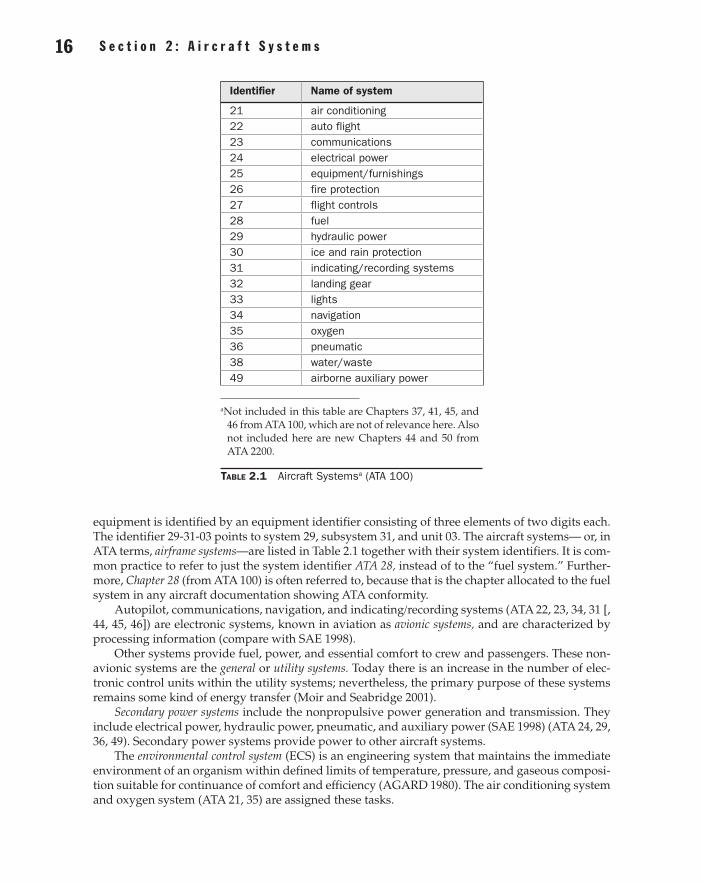
equipment is identified by an equipment identifier consisting of three elements of two digits each. The identifier 29-31-03 points to system 29, subsystem 31, and unit 03. The aircraft systems— or, in ATA terms, airframe systems—are listed in Table 2.1 together with their system identifiers. It is com-mon practice to refer to just the system identifier ATA 28, instead of to the “fuel system.” Further-more, Chapter 28 (from ATA 100) is often referred to, because that is the chapter allocated to the fuel system in any aircraft documentation showing ATA conformity.
Autopilot, communications, navigation, and indicating/recording systems (ATA 22, 23, 34, 31 [, 44, 45, 46]) are electronic systems, known in aviation as avionic systems, and are characterized by processing information (compare with SAE 1998).
Other systems provide fuel, power, and essential comfort to crew and passengers. These non-avionic systems are the general or utility systems. Today there is an increase in the number of elec-tronic control units within the utility systems; nevertheless, the primary purpose of these systems remains some kind of energy transfer (Moir and Seabridge 2001).
Secondary power systems include the nonpropulsive power generation and transmission. They include electrical power, hydraulic power, pneumatic, and auxiliary power (SAE 1998) (ATA 24, 29, 36, 49). Secondary power systems provide power to other aircraft systems.
The environmental control system (ECS) is an engineering system that maintains the immediate environment of an organism within defined limits of temperature, pressure, and gaseous composi-tion suitable for continuance of comfort and efficiency (AGARD 1980). The air conditioning system and oxygen system (ATA 21, 35) are assigned these tasks.
Identifier Name of system
21 air conditioning22 auto flight23 communications24 electrical power25 equipment/furnishings26 fire protection27 flight controls28 fuel29 hydraulic power30 ice and rain protection31 indicating/recording systems32 landing gear33 lights34 navigation35 oxygen36 pneumatic38 water/waste49 airborne auxiliary power
a Not included in this table are Chapters 37, 41, 45, and 46 from ATA 100, which are not of relevance here. Also not included here are new Chapters 44 and 50 from ATA 2200.
Table 2.1 Aircraft Systemsa (ATA 100)
02_Agrawal_ch02_p013-112.indd 16 28/07/17 4:33 pm
S e c t i o n 2 : A i r c r a f t S y s t e m s 17 16 S e c t i o n 2 : A i r c r a f t S y s t e m s
Other aircraft systems are grouped and assigned a specific name often without a formal definition.
Hydraulic systems comprise all systems that apply hydraulic power. In general, these are hydraulic power, flight controls, and landing gear (ATA 29, 27, 32).
Electric systems comprise all systems that apply electric power. In general, these are electric power (ATA 24) and all systems with major electrical consumers. Electrical systems are character-ized by electrical power generation, distribution, and consumption and have to be distinguished from avionic systems.
Pneumatic systems comprise all systems that apply pneumatic power. In general, these are pneumatic and other systems with pneumatic components (ATA 36, 21, 30).
Cabin systems2 comprise all systems with an impact on the cabin of the aircraft and hence with an influence on the passenger (ATA 21, 25, 35, 38, and partially 23, 26, 31, 33).
These groupings depend to a certain extent on the system technologies applied in the aircraft being considered.
CertificationAfter one or several prototype aircraft are designed and manufactured, they go through a series of certification tests in order to show compliance with the certification requirements. Compliance with the requirements may be shown by analysis, ground, or flight test, depending on the requirements or negotiations with the aviation administration. System tests are a substantial part of the certifica-tion program. In Europe, certification of large aeroplanes is based on the Joint Aviation Require-ments (JAR-25), and in the United States it is based on the Airworthiness Standards: Transport Category Airplanes (FAR Part 25). Large aeroplanes are those aircraft with a maximum takeoff mass of more than 5,700 kg. JAR and FAR are very similar; the basic code for JAR-25 is FAR Part 25, and further harmonization of the requirements is in progress. The certification of one or several prototype aircraft leads to a type certificate being issued. Aircraft in series production have to show airworthiness and conformity with the prototype aircraft. In service the aircrafts have to be maintained according to an agreed maintenance schedule to prove continuous airworthiness.
JAR-25 and FAR Part 25 are grouped into several subparts (the following is based on JAR-25).Subpart F, “Equipment,” contains many requirements for aircraft systems.Subpart E, “Power plant,” contains requirements for power plant-related systems.Also Subpart D, “Design and Construction,” contains requirements for aircraft systems.Subpart J, “Gas Turbine Auxiliary Power Unit Installation,” contains requirements for airborne
auxiliary power—i.e., the auxiliary power unit (APU).General information on aircraft systems can be found in section 1301 “Function and installa-
tion” and section 1309 “Equipment, systems and installations” of JAR-25 and FAR Part 25. Section 1309 provides information on safety requirements, loads, and environmental conditions. Table 2.2 provides access to the certification requirements for large airplanes when specific information related to a particular aircraft system is needed.
Interpretative material to most paragraphs is provided:
• FAR: Advisory Circulars (AC) (especially in AC 25-17 and AC 25-22)
• JAR: Advisory Circular Joint (ACJ) (ACJ-25) and Advisory Material Joint (AMJ) (AMJ-25)
2Following the new ATA 2200, “Cabin Systems (ATA 44)” are defined as “Those units and components which furnish means of entertaining the passengers and providing communication within the aircraft and between the aircraft cabin and ground stations. Includes voice, data, music and video transmissions.”
02_Agrawal_ch02_p013-112.indd 17 28/07/17 4:33 pm
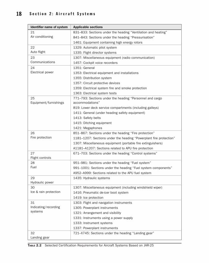
S e c t i o n 2 : A i r c r a f t S y s t e m s 19 18 S e c t i o n 2 : A i r c r a f t S y s t e m s
Identifier name of system Applicable sections
21 Air conditioning
831–833: Sections under the heading “Ventilation and heating”
841–843: Sections under the heading “Pressurisation”
1461: Equipment containing high energy rotors
22 Auto flight
1329: Automatic pilot system
1335: Flight director systems
23 Communications
1307: Miscellaneous equipment (radio communication)
1457: Cockpit voice recorders
24 Electrical power
1351: General
1353: Electrical equipment and installations
1355: Distribution system
1357: Circuit protective devices
1359: Electrical system fire and smoke protection
1363: Electrical system tests
25 Equipment/furnishings
771–793: Sections under the heading “Personnel and cargo accommodations”
819: Lower deck service compartments (including galleys)
1411: General (under heading safety equipment)
1413: Safety belts
1415: Ditching equipment
1421: Megaphones
26 Fire protection
851–867: Sections under the heading “Fire protection”
1181–1207: Sections under the heading “Powerplant fire protection”
1307: Miscellaneous equipment (portable fire extinguishers)
A1181–A1207: Sections related to APU fire protection
27 Flight controls
671–703: Sections under the heading “Control systems”
28 Fuel
951–981: Sections under the heading “Fuel system”
991–1001: Sections under the heading “Fuel system components”
A952–A999: Sections related to the APU fuel system
29 Hydraulic power
1435: Hydraulic systems
30 Ice & rain protection
1307: Miscellaneous equipment (including windshield wiper)
1416: Pneumatic de-icer boot system
1419: Ice protection
31 Indicating/recording systems
1303: Flight and navigation instruments
1305: Powerplant instruments
1321: Arrangement and visibility
1331: Instruments using a power supply
1333: Instrument systems
1337: Powerplant instruments
32 Landing gear
721–X745: Sections under the heading “Landing gear”
Table 2.2 Selected Certification Requirements for Aircraft Systems Based on JAR-25
02_Agrawal_ch02_p013-112.indd 18 28/07/17 4:33 pm
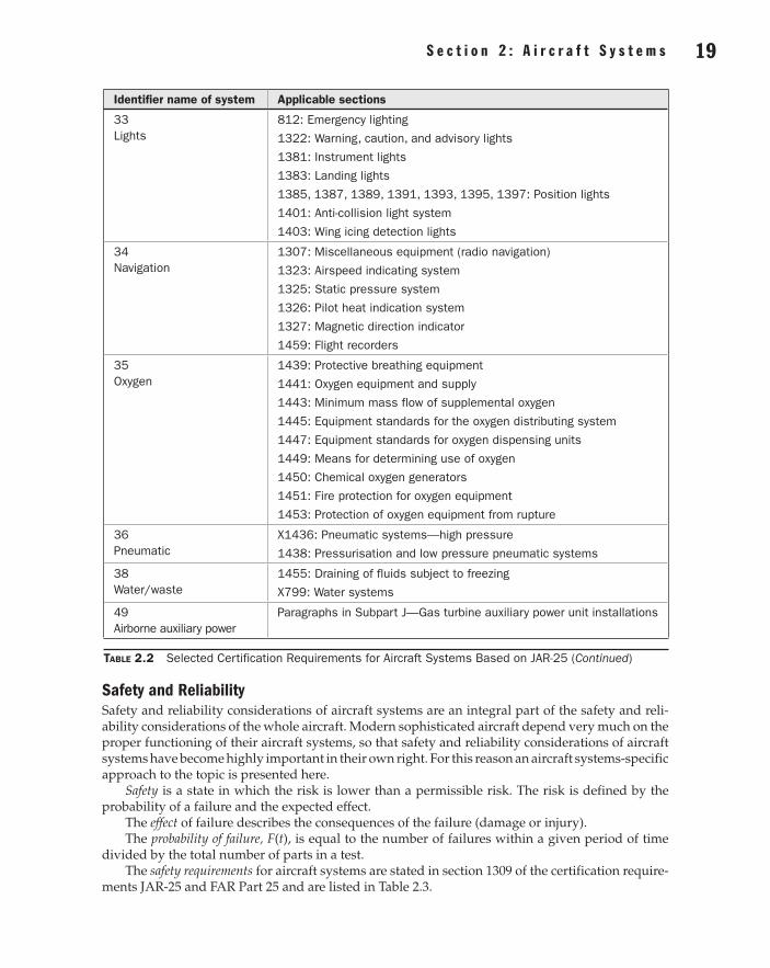
S e c t i o n 2 : A i r c r a f t S y s t e m s 19 18 S e c t i o n 2 : A i r c r a f t S y s t e m s
Identifier name of system Applicable sections
33 Lights
812: Emergency lighting
1322: Warning, caution, and advisory lights
1381: Instrument lights
1383: Landing lights
1385, 1387, 1389, 1391, 1393, 1395, 1397: Position lights
1401: Anti-collision light system
1403: Wing icing detection lights
34 Navigation
1307: Miscellaneous equipment (radio navigation)
1323: Airspeed indicating system
1325: Static pressure system
1326: Pilot heat indication system
1327: Magnetic direction indicator
1459: Flight recorders
35 Oxygen
1439: Protective breathing equipment
1441: Oxygen equipment and supply
1443: Minimum mass flow of supplemental oxygen
1445: Equipment standards for the oxygen distributing system
1447: Equipment standards for oxygen dispensing units
1449: Means for determining use of oxygen
1450: Chemical oxygen generators
1451: Fire protection for oxygen equipment
1453: Protection of oxygen equipment from rupture
36 Pneumatic
X1436: Pneumatic systems—high pressure
1438: Pressurisation and low pressure pneumatic systems
38 Water/waste
1455: Draining of fluids subject to freezing
X799: Water systems
49 Airborne auxiliary power
Paragraphs in Subpart J—Gas turbine auxiliary power unit installations
Table 2.2 Selected Certification Requirements for Aircraft Systems Based on JAR-25 (Continued)
Safety and ReliabilitySafety and reliability considerations of aircraft systems are an integral part of the safety and reli-ability considerations of the whole aircraft. Modern sophisticated aircraft depend very much on the proper functioning of their aircraft systems, so that safety and reliability considerations of aircraft systems have become highly important in their own right. For this reason an aircraft systems-specific approach to the topic is presented here.
Safety is a state in which the risk is lower than a permissible risk. The risk is defined by the probability of a failure and the expected effect.
The effect of failure describes the consequences of the failure (damage or injury).The probability of failure, F(t), is equal to the number of failures within a given period of time
divided by the total number of parts in a test.The safety requirements for aircraft systems are stated in section 1309 of the certification require-
ments JAR-25 and FAR Part 25 and are listed in Table 2.3.
02_Agrawal_ch02_p013-112.indd 19 28/07/17 4:33 pm
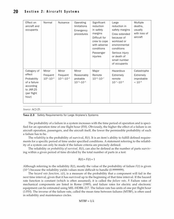
S e c t i o n 2 : A i r c r a f t S y s t e m s 21 20 S e c t i o n 2 : A i r c r a f t S y s t e m s
Effect on aircraft and occupants
Normal Nuisance Operating limitations
Emergency procedures
Significant reduction in safety margins
Difficult for crew to cope with adverse conditions
Passenger injuries
Large reduction in safety margins
Crew extended because of workload or environmental conditions
Serious injury or death of small number of occupants
Multiple deaths, usually with loss of aircraft
Category of effect
Probability of a failure according to JAR-25 (per flight hour)
Minor
Frequent 100–10–2
Minor
Frequent 10–2–10–3
Minor
Reasonably probable 10–3–10–5
Major
Remote 10–5–10–7
Hazardous
Extremely remote 10–7–10–9
Catastrophe
Extremely improbable < 10–9
Source: ACJ-25.
Table 2.3 Safety Requirements for Large Airplane’s Systems
The probability of a failure in a system increases with the time period of operation and is speci-fied for an operation time of one flight hour (FH). Obviously, the higher the effect of a failure is on aircraft operation, passengers, and the aircraft itself, the lower the permissible probability of such a failure has to be.
The reliability is the probability of survival, R(t). It is an item’s ability to fulfill defined require-ments for a specific period of time under specified conditions. A statement referring to the reliabil-ity of a system can only be made if the failure criteria are precisely defined.
The reliability or probability of survival, R(t), can also be defined as the number of parts surviv-ing within a given period of time divided by the total number of parts in a test:
R t F t( ) ( ) 1+ =
Although referring to the reliability R(t), mostly the value of the probability of failure F(t) is given (10–7) because the reliability yields values more difficult to handle (0.9999999).
The hazard rate function, z(t), is a measure of the probability that a component will fail in the next time interval, given that it has survived up to the beginning of that time interval. If the hazard rate function is constant (which is often assumed), it is called the failure rate, λ Failure rates of mechanical components are listed in Rome (1985), and failure rates for electric and electronic equipment can be estimated using MIL-HDBK-217. The failure rate has units of one per flight hour (1/FH). The inverse of the failure rate, called the mean time between failures (MTBF), is often used in reliability and maintenance circles.
MTBF 1/λ=
02_Agrawal_ch02_p013-112.indd 20 28/07/17 4:33 pm
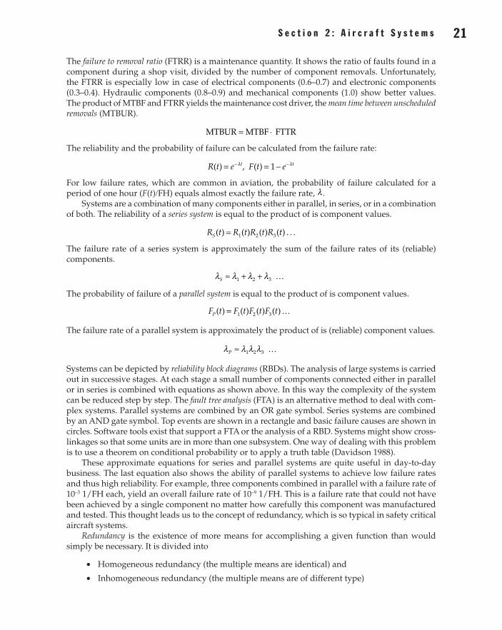
S e c t i o n 2 : A i r c r a f t S y s t e m s 21 20 S e c t i o n 2 : A i r c r a f t S y s t e m s
The failure to removal ratio (FTRR) is a maintenance quantity. It shows the ratio of faults found in a component during a shop visit, divided by the number of component removals. Unfortunately, the FTRR is especially low in case of electrical components (0.6–0.7) and electronic components (0.3–0.4). Hydraulic components (0.8–0.9) and mechanical components (1.0) show better values. The product of MTBF and FTRR yields the maintenance cost driver, the mean time between unscheduled removals (MTBUR).
MTBUR MTBF FTTR= ⋅
The reliability and the probability of failure can be calculated from the failure rate:
R t e t( ) = λ− , F t e t( ) 1= − λ−
For low failure rates, which are common in aviation, the probability of failure calculated for a period of one hour (F(t)/FH) equals almost exactly the failure rate, λ .
Systems are a combination of many components either in parallel, in series, or in a combination of both. The reliability of a series system is equal to the product of is component values.
R t R t R t R tS( ) ( ) ( ) ( ) . . .1 2 3=
The failure rate of a series system is approximately the sum of the failure rates of its (reliable) components.
S 1 2 3λ λ λ λ≈ + +
The probability of failure of a parallel system is equal to the product of is component values.
F t F t F t F tP ( ) ( ) ( ) ( )1 2 3=
The failure rate of a parallel system is approximately the product of is (reliable) component values.
P 1 2 3λ λ λ λ≈
Systems can be depicted by reliability block diagrams (RBDs). The analysis of large systems is carried out in successive stages. At each stage a small number of components connected either in parallel or in series is combined with equations as shown above. In this way the complexity of the system can be reduced step by step. The fault tree analysis (FTA) is an alternative method to deal with com-plex systems. Parallel systems are combined by an OR gate symbol. Series systems are combined by an AND gate symbol. Top events are shown in a rectangle and basic failure causes are shown in circles. Software tools exist that support a FTA or the analysis of a RBD. Systems might show cross-linkages so that some units are in more than one subsystem. One way of dealing with this problem is to use a theorem on conditional probability or to apply a truth table (Davidson 1988).
These approximate equations for series and parallel systems are quite useful in day-to-day business. The last equation also shows the ability of parallel systems to achieve low failure rates and thus high reliability. For example, three components combined in parallel with a failure rate of 10–3 1/FH each, yield an overall failure rate of 10–9 1/FH. This is a failure rate that could not have been achieved by a single component no matter how carefully this component was manufactured and tested. This thought leads us to the concept of redundancy, which is so typical in safety critical aircraft systems.
Redundancy is the existence of more means for accomplishing a given function than would simply be necessary. It is divided into
• Homogeneous redundancy (the multiple means are identical) and
• Inhomogeneous redundancy (the multiple means are of different type)
02_Agrawal_ch02_p013-112.indd 21 28/07/17 4:33 pm
S e c t i o n 2 : A i r c r a f t S y s t e m s 23 22 S e c t i o n 2 : A i r c r a f t S y s t e m s
Inhomogeneous redundancy is divided into:
• Dissimilar redundancy or
• Diversitary redundancy
Safety-critical aircraft systems often show triplex subsystems. The system architecture of safety-critical computers may be even of quadruplex or duo duplex type.
The subsystems of a system with built-in redundancy may all work together. If one subsystem fails, the others will just have to cope with a somewhat higher load. These systems are called active-active systems. Other systems may be of the activestandby type and need to perform a changeover in case of a failure. If the standby subsystem is constantly waiting to be activated, it is on hot standby; otherwise it is on cold standby. The changeover should not be dependent on a changeover unit, because this unit with its own limited reliability might fail and prevent the changeover. If an active-standby concept is applied, the subsystems should take turns doing the job. This could be achieved with a planned changeover before every takeoff. If the same subsystem stays in standby all the time, it may show an (undetected) dormant failure and hence will not be able to take up the job in case of failure of the first subsystem. Systems with a potential of dormant failures need regular maintenance checks and should be avoided.
An assumption has been made in the calculation of parallel systems that the failures of indi-vidual subsystems are independent of each other, that is, that two or more subsystems do not fail simultaneously from precisely the same cause (except purely by chance). However, most systems have the potential of having more than one failure due to a common cause. These failures are called common cause failures (CCFs). They tend to arise from errors made during design, manufacture, maintenance, operation, or environmental effects. For example, loss of power supply could cause both a running and a standby pump to fail (design error), or an empty fuel tank could cause all engines to quit (error in operation). Because these failure modes may appear to be outside the system being assessed, they can easily be overlooked, leading to too-optimistic assessments. Methods to avoid common cause failures in the design stage are the application of
• Inhomogeneous redundancy (see above)
• Segregation in the rooting of redundant wires, pipes, and ducts
• Separation of redundant components
• Placement of safety-critical components in safe areas
• Design of redundant components or software programs by independent teams with different (software) tools
An aircraft should not only be safe to fly, it should also show very few errors that need the attention of maintenance personnel. In this respect we face a problem with high safety require-ments. High safety requirements lead to the application of redundancy and hence more subsys-tems. The probability of a failure leading to the loss of the overall function can be reduced by redundancy, but the probability of occurrence of any failure anywhere in the system is increased. Two subsystems with a failure rate of 10–3 1/FH each yield an overall probability of failure of about 10–6 and a probability of any failure of 2 10 3⋅ − (based on a 1-hour operation). Three subsystems yield an overall probability of failure of 10–9 and a probability of any failure of already 3 10 3⋅ − . The level of safety during flight can only be achieved if all subsystems work properly before takeoff, but, as we have seen, the probability for any failure increases with an increased number of subsys-tems. These thoughts lead to what is called availability and dispatch reliability.
The steady state availability is defined as the probability that a system will be available when required, or as the proportion of total time that the system is available for use. Therefore, the
02_Agrawal_ch02_p013-112.indd 22 28/07/17 4:33 pm
S e c t i o n 2 : A i r c r a f t S y s t e m s 23 22 S e c t i o n 2 : A i r c r a f t S y s t e m s
availability of a system is a function of its failure rate λ and of its repair rate 1/MTTRµ = , where MTTR is the mean time to repair:
A MTBFMTBF + MTTRSS
µλ µ
= =+
The instantaneous availability, or probability that the system will be available at time t, is
A eIt( )µ
λ µλ
λ µ=
++
+λ µ− +
Often it is more revealing to consider system unavailability, U = 1 – A. The instantaneous avail-ability of an aircraft at the moment of dispatch from the gate is called dispatch reliability. Dispatch reliability, for technical reasons, primarily depends on the combined dispatch reliability of the air-craft systems. The airlines monitor their fleets’ dispatch reliability very carefully because high dis-patch unreliability leads to delays and cancellations of flights and incurs delay and cancellation costs (see below). Dispatch reliability depends on the maturity of an aircraft program and is on the order of 0.99. A method to increase dispatch reliability is the introduction of built-in test equipment (BITE) into electronic systems. Though this adds complexity and might result in spurious failure indica-tions, it can greatly reduce maintenance times by providing an instantaneous indication of failure location. Another method is to provide extra redundancy above the level required for safety reasons. This would than allow to dispatch with one subsystem inoperative. Components that are not needed for takeoff may be known as flying spares. The pilot gets a clear indication about which subsystems or components need to be available at takeoff from the minimum equipment list (MEL), written by the airline on the basis of the master minimum equipment list (MMEL) provided by the manufacturer and approved by the authorities.
Reliability assurance during the aircraft system design applies a couple of different methods, including:
• Drawing a fault tree for a fault tree analysis (FTA) (see above) starts from consideration of system failure effects, referred to as top event. The analysis proceeds by determining how these can be caused by lower-level failures. In this way it is a top-down approach.
• The reliability apportionment breaks an overall system reliability requirement down into individual subsystem reliabilities. This is common in large systems when different design teams of subcontractors are involved. Clearly it follows a top-down approach.
• In contrast, the failure mode, effects, and criticality analysis (FMECA) (MILSTD-1629) follows a bottom-up approach. It considers each mode of failure of every component of a system to ascertain the effects on system operation and defines a failure mode criticality number.
• The zonal safety analysis (ZSA), rather than looking at an aircraft from a functional point of view, looks at the components’ location. The ZSA checks installation rules and checks the effects of events originating within the zone, in other zones, or on the outside.
Software defies the above calculations and methods. However, information can be drawn from RTCA/DO-178B, which deals with software considerations in airborne systems and equipment. Environmental conditions for airborne equipment are presented in RTCA/DO-160D.
MassMass estimation of aircraft systems is part of the mass (or weight) estimation of the whole aircraft.
The mass of all the aircraft systems mSYS amounts to 23–40% of the aircraft’s empty mass mOE, where mOE is the mass related to the operational empty weight (OEW). The figure 23% is true in
02_Agrawal_ch02_p013-112.indd 23 28/07/17 4:33 pm
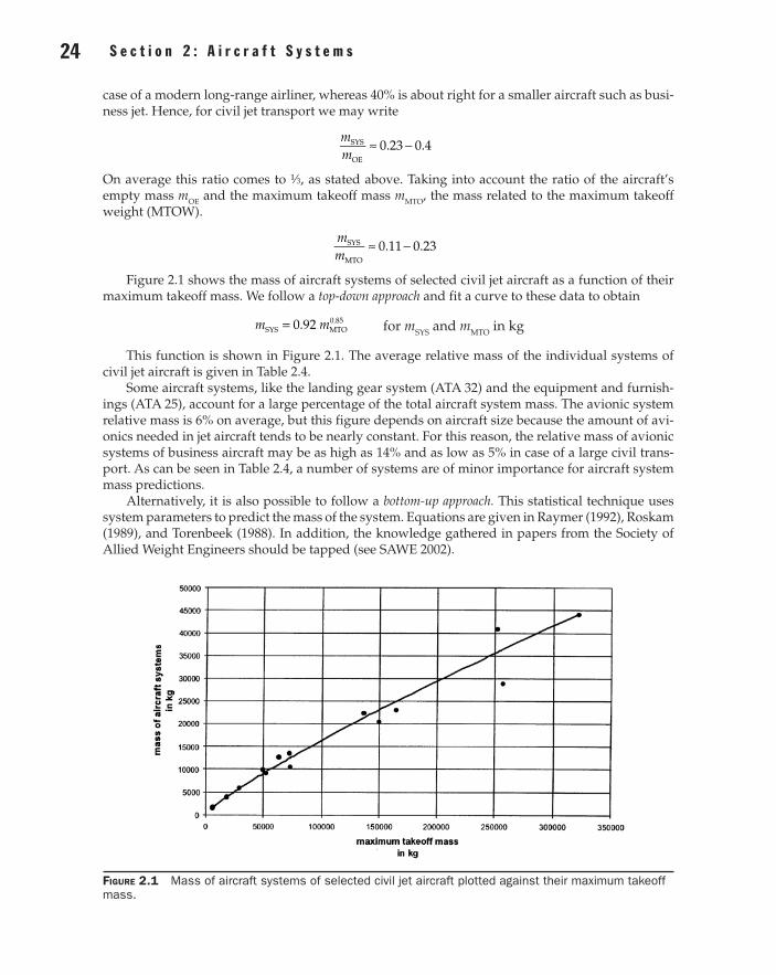
S e c t i o n 2 : A i r c r a f t S y s t e m s 25 24 S e c t i o n 2 : A i r c r a f t S y s t e m s
case of a modern long-range airliner, whereas 40% is about right for a smaller aircraft such as busi-ness jet. Hence, for civil jet transport we may write
mm
0.23 0.4SYS
OE
≈ −
On average this ratio comes to 1⁄3, as stated above. Taking into account the ratio of the aircraft’s empty mass mOE and the maximum takeoff mass mMTO, the mass related to the maximum takeoff weight (MTOW).
mm
0.11 0.23SYS
MTO
≈ −
Figure 2.1 shows the mass of aircraft systems of selected civil jet aircraft as a function of their maximum takeoff mass. We follow a top-down approach and fit a curve to these data to obtain
m m0.92SYS MTO0.85= for mSYS and mMTO in kg
This function is shown in Figure 2.1. The average relative mass of the individual systems of civil jet aircraft is given in Table 2.4.
Some aircraft systems, like the landing gear system (ATA 32) and the equipment and furnish-ings (ATA 25), account for a large percentage of the total aircraft system mass. The avionic system relative mass is 6% on average, but this figure depends on aircraft size because the amount of avi-onics needed in jet aircraft tends to be nearly constant. For this reason, the relative mass of avionic systems of business aircraft may be as high as 14% and as low as 5% in case of a large civil trans-port. As can be seen in Table 2.4, a number of systems are of minor importance for aircraft system mass predictions.
Alternatively, it is also possible to follow a bottom-up approach. This statistical technique uses system parameters to predict the mass of the system. Equations are given in Raymer (1992), Roskam (1989), and Torenbeek (1988). In addition, the knowledge gathered in papers from the Society of Allied Weight Engineers should be tapped (see SAWE 2002).
Figure 2.1 Mass of aircraft systems of selected civil jet aircraft plotted against their maximum takeoff mass.
02_Agrawal_ch02_p013-112.indd 24 28/07/17 4:33 pm
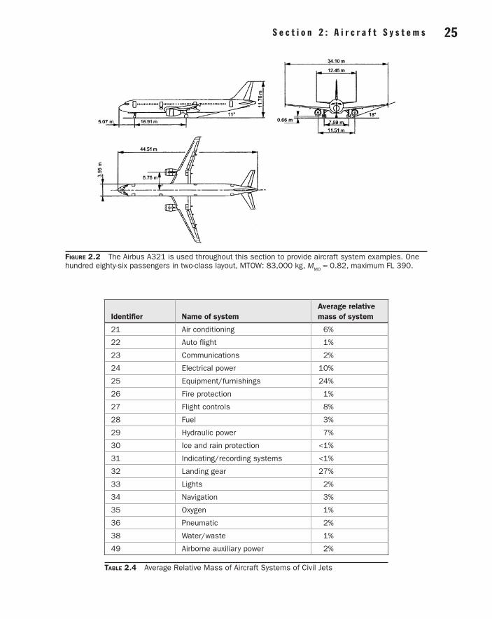
S e c t i o n 2 : A i r c r a f t S y s t e m s 25 24 S e c t i o n 2 : A i r c r a f t S y s t e m s
Figure 2.2 The Airbus A321 is used throughout this section to provide aircraft system examples. One hundred eighty-six passengers in two-class layout, MTOW: 83,000 kg, MMO = 0.82, maximum FL 390.
Identifier Name of systemAverage relative mass of system
21 Air conditioning 6%
22 Auto flight 1%
23 Communications 2%
24 Electrical power 10%
25 Equipment/furnishings 24%
26 Fire protection 1%
27 Flight controls 8%
28 Fuel 3%
29 Hydraulic power 7%
30 Ice and rain protection <1%
31 Indicating/recording systems <1%
32 Landing gear 27%
33 Lights 2%
34 Navigation 3%
35 Oxygen 1%
36 Pneumatic 2%
38 Water/waste 1%
49 Airborne auxiliary power 2%
Table 2.4 Average Relative Mass of Aircraft Systems of Civil Jets
02_Agrawal_ch02_p013-112.indd 25 28/07/17 4:33 pm
S e c t i o n 2 : A i r c r a f t S y s t e m s 27 26 S e c t i o n 2 : A i r c r a f t S y s t e m s
Statistics of aircraft system mass have to take as many aircraft into account as possible in order to broaden the statistical base. This, however, is really possible only if mass data are based on com-parable and detailed mass breakdowns. Unfortunately, there are many quite different breakdowns in use, and it is found that system boundaries overlap from one method to another or are not well defined in the first place. So in the present situation it is very difficult to use and compare mass data and mass equations based on one of these breakdowns in another setting. This situation adds to the difficulties that exist with statistical methods anyhow and explains why statistical mass equations for systems or subsystems do not provide particularly reliable data.
Boeing has used a breakdown format called Weight Research Data 1 (WRD1). In the literature, breakdowns very similar to WRD1 can be found. Airbus uses so-called Weight Chapters. Another approach is given with MIL-STD-1374. Above we have used a mass breakdown according to the ATA 100 chapter numbering. ATA 100 also includes a widely accepted mass breakdown for weight and balance manuals. This breakdown, however, provides only as much detail as needed in aircraft operation but not enough detail for aircraft system design.
Note that aircraft system mass predictions deteriorate in accuracy when the level of detail is increased. For its old class I weight prediction method, Boeing estimates the prediction of single systems to be off by as much as ±90%. In contrast, the resultant mass of all systems combined is claimed to be off by not more than ±16% (Boeing 1968). This is because many inaccuracies com-bined fortunately cancel out to a certain extent.
Detailed system mass predictions are also necessary for center of gravity (CG) calculation for the aircraft. The main landing gear accounts for about 87% and the nose landing gear for the remaining 13% of the complete landing gear mass. With known positions of nose and main landing gear, this information can be fed into the CG calculation of the aircraft. The CG of the other systems can roughly be assumed at a point 40–50% of the fuselage length aft of the aircraft nose.
Practical mass predictions will look like this: In the early design stage, statistical methods are used. The aircraft manufacturer can also use the information contained in the mass database of older air-craft for the new design. In a later design stage a subcontractor will offer a system or an item of equipment. The subcontractor probably has quite a good idea what the item’s mass will be from a comparison with similar items already built. If the required size of equipment is different from an older one, a mass estimate may be obtained from scaling. In the final development stage, mass accounting can be based on the actual mass of components that are already delivered to the manufacturer.
There is another virtue in mass predictions: the system mass has been used for rough cost calculations. This is possible when, from statistics, costs per unit mass are known and costs are assumed to be proportional with mass. Evidently, the concept of calculating costs from mass fails if expensive mass reduction programs are being applied. The concept also fails if highly sophisticated technologies are applied to reduce mass that are not considered in the established cost per unit mass.
PowerGliders use the energy of up-currents, while solar-powered vehicles use the energy from the sun. Human-powered flight has also been demonstrated. Propulsive power for any other “down to earth” flying depends on fuel. This fuel is used in the aircraft main engines. Secondary power systems (hydraulic power, electrical power, pneumatic power) in turn draw on engine power to supply their client systems with nonpropulsive power in all those cases where functions are not directly actu-ated by the pilot’s muscles. This is the simple picture of the aircraft power management. However, there is more to it, due to safety requirements and the need for autonomous operation of the aircraft on the ground with engines shut down.
Various secondary power sources are available in the air and on the ground. Secondary power loads may be grouped into two major categories. Power conversion transforms secondary power from one form into another.
02_Agrawal_ch02_p013-112.indd 26 28/07/17 4:33 pm
S e c t i o n 2 : A i r c r a f t S y s t e m s 27 26 S e c t i o n 2 : A i r c r a f t S y s t e m s
An auxiliary power unit (APU) (see above) is used to produce power from fuel independent of the main engines. An APU is a gas turbine engine. Most often it produces electrical power and pneumatic power. A ram air turbine (RAT) (see Subsection 2.8) is used to produce hydraulic or elec-trical power from the kinetic energy of the air passing by the aircraft. This is possible even without fuel and without the main engines running—at least as long as the aircraft soars down consuming its potential energy. Except for the pilot’s own energy, the aircraft batteries are the last and very limited source of energy on board.
Ground power may be available on the apron or in the hangar. The aircraft may be supplied directly with electricity, high-pressure hydraulic fluid, pressurized air, and/or air conditioned air. Human power could work a hand pump in the hydraulic system. If only electrical ground power is available, the aircraft depends on its secondary power conversion capabilities to activate the hydraulic and pneumatic system. Without ground equipment and with engines shut down, the aircraft may operate autonomously if it is equipped with an auxiliary power unit (APU).
First of all, secondary power loads may be grouped into:
• Technical loads consumed by equipment required to operate the aircraft safely
• Commercial loads consumed by equipment required to increase passenger comfort and satisfaction, given the airline’s need to provide these services
Power conversion among different3 secondary power systems is used to increase overall system reliability. If we consider electrical power, hydraulic power, and pneumatics:
• Six different unidirectional conversions are possible. Examples are:
• Electrical to hydraulic power conversion: electric motor-driven pump
• Pneumatic to hydraulic power conversion: air turbine motor-driven pump
• Hydraulic to electrical power conversion: hydraulic motor-driven generator
• Three different bidirectional conversions are possibilities that allow a two-way power conversion among two different secondary power systems within one conversion unit.
For many years hydraulic, pneumatic, and electrical power supply in commercial aircraft had been sufficient to meet the demands from technical and commercial loads. System design empha-sized reliable, lightweight solutions. From fuel input to system output, very low overall efficiencies were accepted in exchange.
In recent years it has been observed that aircraft face increasing technical loads. Also, market trends together with increasing flight durations have resulted in higher commercial loads, caused, for example, by today’s standards in in-flight entertainment. Possibilities for power off-takes do not increase proportionally with aircraft size. Large modern civil aircraft are therefore likely to face limitations of cost effectiveness, geometry, or weight with present-day technologies in an attempt to meet these new power load levels. The aerospace industry has identified a potential deadlock, where power needs will exceed the maximum available power supply.
In the future a move toward electrical power as a single source to meet secondary power demands is expected to be a solution to the problem. The last aircraft generation brought steering by wire. The next generation of aircraft might bring power by wire.
3Power conversion is even applied within one type of secondary power system: the hydraulic system. Transport category aircraft apply several independent hydraulic systems. Among pairs of these hydraulic systems unidirectional or bidirectional hydraulic power transfer without the interchange of hydraulic fluid can be desirable. For this purpose, power transfer units (PTU) (ARP 1280) are used. They are built by coupling a hydraulic motor and a hydraulic pump via a connecting shaft.
02_Agrawal_ch02_p013-112.indd 27 28/07/17 4:33 pm
S e c t i o n 2 : A i r c r a f t S y s t e m s 29 28 S e c t i o n 2 : A i r c r a f t S y s t e m s
Costs and Trade-Off StudiesTrade-off studies play an important roll in aircraft system design. Trade-off studies try to find the best among several system design proposals. Safety aspects allow no compromise because certifi-cation regulations have to be closely followed. Also, performance aspects leave little room because usually only as much performance as necessary to do the job will be allowed for. More powerful aircraft systems will unnecessarily produce costs that add to the overall costs of the aircraft. Clearly, costs need to be reduced as much as possible to come up with a viable product. Therefore, it is the costs aspect that is usually decisive in trade-off studies of which system design will get on board the aircraft.
At the aircraft system level, evaluations are done in the early design stage by looking sepa-rately at various aspects:
• Mass
• Maintainability
• Reliability
• System price
• Other specific criteria depending on the aircraft system in question
Based on these separate evaluations, the simplest way to come up with one single figure of merit for a proposal is to define subjectively a weighted sum of the results based on the individual criteria.
In contrast to the above approach, at the aircraft level an evaluation is traditionally based pri-marily on one single figure: the direct operating costs (DOC). DOCs take account of criteria such as mass, maintainability, and aircraft price, but combine these separate parameters unambiguously by calculating their economical implications. Subjective manipulations of the results are largely avoided in this way.
Unfortunately, aircraft DOC methods cannot be taken as is for applying this advantage to an aircraft system evaluation. In contrast to aircraft DOC methods, a DOC method on the systems level must incorporate many system-specific parameters. Therefore, a DOC method for aircraft systems called DOCSYS has been developed (Scholz 1998) which follows the principles of aircraft DOC methods as closely as possible while taking aircraft system peculiarities into account as much as necessary.
C C C C C CF MDOC,SYS DEP DEL SH= + + + +
where CDEP = depreciation of the system (a function of system price) CF = fuel costs caused by the system CM = direct maintenance costs caused by the system CDEL = delay and cancellation costs caused by the system CSH = capital costs caused by necessary system spare parts on stock (spare holding)
The fuel costs, CF, are due to:
• Transportation of the system’s mass (fixed or variable during flight) (taking into account the lift-to-drag ratio of the aircraft and the specific fuel consumption of the engines)
• Power off-takes from the engines (by electrical generators or hydraulic pumps)
• Bleed air off-takes (for the pneumatic system)
• Ram air off-takes (e.g., for the air conditioning system)
02_Agrawal_ch02_p013-112.indd 28 28/07/17 4:33 pm
S e c t i o n 2 : A i r c r a f t S y s t e m s 29 28 S e c t i o n 2 : A i r c r a f t S y s t e m s
• Additional drag caused by the presents of aircraft systems, subsystems, or single parts (e.g., due to drain masts)
In contrast to Scholz (1998), who combines various system aspects to U.S. dollars, Shustrov (1998) combines system mass effects and effects related to the system’s energy consumption to a quantity called starting mass.
Proprietary methods for the evaluation of aircraft systems are in use at aircraft manufacturers and subcontractors.
2.2 Air Conditioning (ATA 21)Air conditioning as defined by ATA 100:
Those units and components which furnish a means of pressurizing, heating, cooling, moisture control-ling, filtering and treating the air used to ventilate the areas of the fuselage within the pressure seals. Includes cabin supercharger, equipment cooling, heater, heater fuel system, expansion turbine, valves, scoops, ducts, etc.
Fundamentals
Impact of Atmospheric ParametersIn the troposphere, the air temperature decreases with increasing altitude. In the stratosphere above 11,000 m (36,089 ft), the air temperature is at constant –56.5 °C. The air pressure also decreases with altitude. Although oxygen amounts to approximately 21% independent of altitude, the partial pressure4 of oxygen drops with increasing altitude. Our body is used to a partial oxygen pressure of about 0.21 times sea level pressure. If we want to survive at high altitudes, either (a) the oxygen fraction has to be increased (using an oxygen system), or (b) the total pressure has to be maintained close to sea level pressure (using a pressurization system). For civil aircraft generally option (b) is applied; flights in nonpressurized cabins5 without supplemental oxygen are limited to an altitude of 10,000 ft. Military aircraft use a combination of (a) and (b); cabin altitude6 does not exceed about 20,000 ft.
Purpose of Air Conditioning SystemsThe purpose of the air conditioning system is to make the interior environment of the aircraft com-fortable for human beings. Depending on the type of aircraft and altitude of operation, this may involve only ventilation of the cabin by supplying a flow of fresh air using air vents. If the tempera-ture must be adjusted, some method of heating or cooling is required. At high altitudes the aircraft can fly above most of the weather conditions that contain turbulence and make flight uncomfort-able. Additionally, the fuel efficiency of the aircraft is increased. Pressurization is necessary if the aircraft is operated at these high altitudes. In some parts of the world the relative humidity7 is quite high. Water extractors are therefore used for dehumidification of the cabin air. This is necessary to
4Partial pressure: “The pressure exerted by one gas in a mixture of gases; equal to the fraction … of one gas times the total pressure” (AIR 171).5Nonpressurized cabin: “An airplane cabin that is not designed … for pressurizing and which will, therefore, have a cabin pressure equal to that of the surrounding atmosphere” (SAE 1998).6Cabin altitude: “The standard altitude at which atmospheric pressure is equal to the cabin pressure” (SAE 1998).7Relative humidity: “The ratio, expressed as percentage, of the amount of water vapor … actually present in the air, to the amount of water vapor that would be present if the air were saturated with respect to water at the same temperature and pressure” (SAE 1998).
02_Agrawal_ch02_p013-112.indd 29 28/07/17 4:33 pm