Embed Size (px)
Citation preview
© NACE S tanda rd MR0175-2002
I tem No. 21304
T H E C O R R O S I O N S O C I E T Y
Standard Material Requirements
Sulfide Stress Cracking Resistant Metallic Materials for Oilfield Equipment
This NACE International standard represents a consensus of those individual members who have reviewed this document, its scope, and provisions. Its acceptance does not in any respect preclude anyone, whether he has adopted the standard or not, from manufacturing, marketing, purchasing, or using products, processes, or procedures not in conformance with this standard. Nothing contained in this NACE International standard is to be construed as granting any right, by implication or otherwise, to manufacture, sell, or use in connection with any method, apparatus, or product covered by Letters Patent, or as indemnifying or protecting anyone against liability for infringement of Letters Patent. This standard represents minimum requirements and should in no way be interpreted as a restriction on the use of better procedures or materials. Neither is this standard intended to apply in all cases relating to the subject. Unpredictable circumstances may negate the usefulness of this standard in specific instances. NACE International assumes no responsibility for the interpretation or use of this standard by other parties and accepts responsibility for only those official NACE International interpretations issued by NACE International in accordance with its governing procedures and policies which preclude the issuance of interpretations by individual volunteers.
Users of this NACE International standard are responsible for reviewing appropriate health, safety, environmental, and regulatory documents and for determining their applicability in relation to this standard prior to its use. This NACE International standard may not necessarily address all potential health and safety problems or environmental hazards associated with the use of materials, equipment, and/or operations detailed or referred to within this standard. Users of this NACE International standard are also responsible for establishing appropriate health, safety, and environmental protection practices, in consultation with appropriate regulatory authorities if necessary, to achieve compliance with any existing applicable regulatory requirements prior to the use of this standard.
CAUTIONARY NOTICE: NACE International standards are subject to periodic review, and may be revised or withdrawn at any time without prior notice. NACE International requires that action be taken to reaffirm, revise, or withdraw this standard no later than five years from the date of initial publication. The user is cautioned to obtain the latest edition. Purchasers of NACE International standards may receive current information on all standards and other NACE International publications by contacting the NACE International Membership Services Department, 1440 South Creek Dr., Houston, Texas 77084-4906 (telephone +1 [281)228-6200).
Revised 2002-01-01 Approved March 1975
NACE International 1440 South Creek Dr.
Houston, Texas 77084-4906 +1 (281)228-6200
ISBN 1-57590-021-1 © 2002, NACE International
MR0175-2002
Foreword
This NACE standard materials requirement is one step in a series of committee studies, reports, symposia, and standards that have been sponsored by former Group Committee T-1 (Corrosion Control in Petroleum Production) relating to the general problem of sulfide stress cracking (SSC) of metals. Much of this work has been directed toward the oil- and gas-production industry. This standard is a materials requirement for metals used in oil and gas service exposed to sour gas, to be used by oil and gas companies, manufacturers, engineers, and purchasing agents. Many of the guidelines and specific requirements in this standard are based on field experience with the materials listed, as used in specific components, and may be applicable to other components and equipment in the oil-production industry or to other industries, as determined by the user. Users of this standard must be cautious in extrapolating the content of this standard for use beyond its scope.
The materials, heat treatments, and metal-property requirements given in this standard represent the best judgment of Task Group 081 (formerly T-1F-1) and its administrative Specific Technology Group (STG) 32 on Oil and Gas Production—Metallurgy (formerly Unit Committee T-1F on Metallurgy of Oilfield Equipment).
This NACE standard updates and supersedes all previous editions of MR0175. The original 1975 edition of the standard superseded NACE Publication 1F166 (1973 Revision) titled "Sulfide Cracking-Resistant Metallic Materials for Valves for Production and Pipeline Service," and NACE Publication 1B163 titled "Recommendation of Materials for Sour Service" (which included Tentative Specifications 150 on valves, 51 on severe weight loss, 60 on tubular goods, and 50 on nominal weight loss).
This standard will be revised as necessary to reflect changes in technology. (See Paragraph 1.6.)
Whenever possible, the recommended materials are defined by reference to accepted generic descriptors (such as UNS ( 1 ) numbers) and/or accepted standards, such as AISI, ( 2 ) API , ( 3 ) ASTM, < 4 )
or DIN ( 5 ) standards.
In NACE standards, the terms shall, must, should, and may are used in accordance with the definitions of these terms in the NACE Publications Style Manual, 4th ed., Paragraph 7.4.1.9. Shall and must are used to state mandatory requirements. Should is used to state something considered good and is recommended but is not mandatory. May is used to state something considered optional.
( ' Metals and Alloys in the Unified Numbering System (latest revision), a joint publication of ASTM International and the Society of Automotive Engineers Inc. (SAE), 400 Commonwealth Dr., Warrendale, PA 15096. ( 2 ) American Iron and Steel Institute (AISI), 1133 15th St. NW, Washington, DC 20005-2701. ( 3 ) American Petroleum Institute (API), 1220 L St. NW, Washington, DC 20005. ( 4 ) ASTM International, 100 Ban Harbor Dr., West Conshohocken, PA 19428-2959. ( 5 ) Deutsches Institutfur Normung (DIN), Postfach 1107, D-1000 Berlin 30, Federal Republic of Germany.
Arrows in the margins indicate technical or major editorial revisions that were approved by N A C E International S T G 32 and incorporated into the 2002 edition of MR0175. Revis ions are not indicated in the tables or index.
N A C E International
MR0175-2002
NACE International Standard
Material Requirements
Sulfide Stress Cracking Resistant Metallic Materials for Oilfield Equipment
Contents
1. General 1 1.1 Scope 1 1.2 Applicability 1 1.3 MR0175 Application 1 1.4 Control of Sulfide Stress Cracking (SSC) 2 1.5 Acceptable Materials 2 1.6 Procedures for the Addition of New Materials or Processes 2 1.7 Hardness Requirements 3 1.8 Materials Handling 3 1.9 Procurement 3 1.10 Material Replacement 3 2. Definitions 7 3. Ferrous Metals 9 3.1 General 9 3.2 Carbon and Low-Alloy Steels 9 3.3 Free-Machining Steels 10 3.4 Cast Iron 10 3.5 Austenitic Stainless Steels 10 3.6 Ferritic Stainless Steels 13 3.7 Martensitic Stainless Steels 13 3.8 Precipitation-Hardening Stainless Steels 14 3.9 Duplex Stainless Steels 14 4. Nonferrous Metals 15 4.1 General 15 4.2 Other Alloys 18 5. Fabrication 19 5.1 General 19 5.2 Overlays 19 5.3 Welding 19 5.4 Identification Stamping 19 5.5 Threading 19 5.6 Cold-Deformation Processes 20 6. Bolting 20 6.1 General 20 6.2 Exposed Bolting 20 6.3 Nonexposed Bolting 20 7. Platings and Coatings 20 7.1 General 20
ii NACE International
MR0175-2002
7.2 Nitriding 20 8. Special Components 20 8.1 General 20 8.2 Bearings 20 8.3 Springs 21 8.4 Instrumentation and Control Devices 21 8.5 Seal Rings 21 8.6 Snap Rings 21 8.7 Duplex Stainless Steel for Wellhead Components 21 8.8 Special Process Wear-Resistant Parts 22 9. Valves and Chokes 22 9.1 General 22 9.2 Shafts, Stems, and Pins 22 9.3 Internal Valve and Pressure Regulator Components 22 10. Wells, Flow Lines, Gathering Lines, Facilities, and Field Processing Plants 22 10.1 General 22 10.2 Wells 22 10.3 Subsurface Equipment 23 10.4 Wellheads 24 10.5 Flow Lines and Gathering Lines 24 10.6 Production Facilities 24 10.7 Compressors and Pumps 24 10.8 Pipe Fittings 24 11. Drilling and Well-Servicing Equipment 24 11.1 General 24 11.2 Control of Drilling and Well-Servicing Environments 24 11.3 Drilling Equipment 25 11.4 Blowout Preventer (BOP) 25 11.5 Choke Manifolds and Choke and Kill Lines 25 11.6 Drill Stem Testing 25 11.7 Formation-Testing Tools 25 11.8 Floating Drilling Operations 26 11.9 Well-Servicing Equipment 26 References 26 Tables 1. Description of Test Levels 4 2. Test Data 4 3. Stainless Steels Acceptable for Direct Exposure to Sour Environments 28 4. Nonferrous Materials Acceptable for Direct Exposure to Sour Environments 29 5. Acceptable API and ASTM Specifications for Tubular Goods 31 6. Acceptable Materials for Subsurface Equipment for Direct Exposure to Sour
Environments 32 7. Other Sources of Material Standards 32 Figures Figure 1: Sour Gas Systems 5 Figure 2: Sour Multiphase Systems 6 Index History of the Addition of Materials to MR0175 33
NACE International iii
MR0175-2002
Section 1:
1.1 Scope
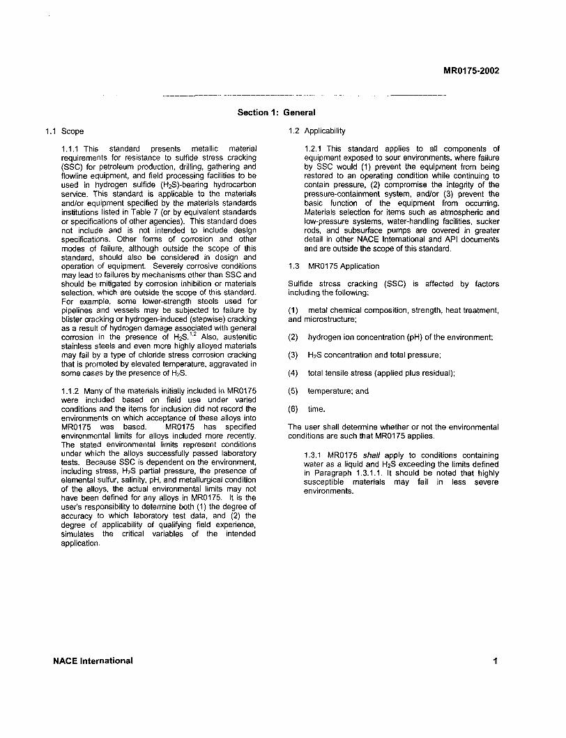
1.1.1 This standard presents metallic material requirements for resistance to sulfide stress cracking (SSC) for petroleum production, drilling, gathering and flowline equipment, and field processing facilities to be used in hydrogen sulfide (H2S)-bearing hydrocarbon service. This standard is applicable to the materials and/or equipment specified by the materials standards institutions listed in Table 7 (or by equivalent standards or specifications of other agencies). This standard does not include and is not intended to include design specifications. Other forms of corrosion and other modes of failure, although outside the scope of this standard, should also be considered in design and operation of equipment. Severely corrosive conditions may lead to failures by mechanisms other than SSC and should be mitigated by corrosion inhibition or materials selection, which are outside the scope of this standard. For example, some lower-strength steels used for pipelines and vessels may be subjected to failure by blister cracking or hydrogen-induced (stepwise) cracking as a result of hydrogen damage associated with general corrosion in the presence of H2S.1'2 Also, austenitic stainless steels and even more highly alloyed materials may fail by a type of chloride stress corrosion cracking that is promoted by elevated temperature, aggravated in some cases by the presence of H2S.
1.1.2 Many of the materials initially included in MR0175 were included based on field use under varied conditions and the items for inclusion did not record the environments on which acceptance of these alloys into MR0175 was based. MR0175 has specified environmental limits for alloys included more recently. The stated environmental limits represent conditions under which the alloys successfully passed laboratory tests. Because SSC is dependent on the environment, including stress, H2S partial pressure, the presence of elemental sulfur, salinity, pH, and metallurgical condition of the alloys, the actual environmental limits may not have been defined for any alloys in MR0175. It is the user's responsibility to determine both (1) the degree of accuracy to which laboratory test data, and (2) the degree of applicability of qualifying field experience, simulates the critical variables of the intended application.
General
1.2 Applicability
1.2.1 This standard applies to all components of equipment exposed to sour environments, where failure by SSC would (1) prevent the equipment from being restored to an operating condition while continuing to contain pressure, (2) compromise the integrity of the pressure-containment system, and/or (3) prevent the basic function of the equipment from occurring. Materials selection for items such as atmospheric and low-pressure systems, water-handling facilities, sucker rods, and subsurface pumps are covered in greater detail in other NACE International and API documents and are outside the scope of this standard.
1.3 MR0175 Application
Sulfide stress cracking (SSC) is affected by factors including the following:
(1) metal chemical composition, strength, heat treatment, and microstructure;
(2) hydrogen ion concentration (pH) of the environment;
(3) H2S concentration and total pressure;
(4) total tensile stress (applied plus residual);
(5) temperature; and
(6) time.
The user shall determine whether or not the environmental conditions are such that MR0175 applies.
1.3.1 MR0175 shall apply to conditions containing water as a liquid and H2S exceeding the limits defined in Paragraph 1.3.1.1. It should be noted that highly susceptible materials may fail in less severe environments.
NACE International 1
MR0175-2002
1.3.1.1 All gas,1 ' gas condensate, ' 1 and sour crude oil ' 8 ' 9 ' (except as noted)
When the partial pressure of H 2S in a wet (water as a liquid) gas phase of a gas, gas condensate, or crude oil system is equal to or exceeds 0.0003 MPa abs (0.05 psia).
1.3.2 MR0175 need not apply (the user shall determine) when the following conditions exist:
1.3.2.1 Low-pressure gas
When the total pressure is less than 0.4 MPa abs (65 psia).
1.3.2.2 Low-pressure oil and gas multiphase systems
When the total pressure is less than 1.8 MPa abs (265 psia), the maximum gas:oil ratio (SCF:bbl [SCF:bbl]) is 5,000 or less, and the H 2S content is less than 15 mol% and the H2S partial pressure is less than 0.07 MPa abs (10 psia).
1.3.3 MR0175 need not apply (the user shall determine) for the following conditions:
1.3.3.1 Salt-water wells and salt-water handling facilities. These are covered by NACE Standard RP0475.3
1.3.3.2 Weight-loss corrosion and corrosion fatigue.
1.3.3.3 Refineries and chemical plants.
1.4 Control of SSC
1.4.1 SSC may be controlled by any or all of the following measures:
(1) using the materials and processes described in this standard;
(3) isolating the components from the sour environment.
Metals susceptible to SSC have been used successfully by controlling drilling or workover fluid properties, during drilling and workover operations, respectively.
1.5 Metallic materials have been included in this standard as acceptable materials based on their resistance to SSC either in actual field applications, in SSC tests, or both. Many alloys included in the first edition of MR0175 had proved to be satisfactory in sour service even though they might have cracked in standard SSC tests, such as those addressed in NACE Standard TM0177.4 Because MR0175 was incorporated as a mandatory requirement by certain regulatory agencies, it soon became impossible to use satisfactory field applications as a criterion for the addition of new materials or processes; i.e., because regulations prohibited the use of materials not specifically approved in MR0175, proponents of new materials or processes could not establish a history of satisfactory field application. Consequently, some materials in the standard may not perform as well in SSC tests as newer materials that have been excluded on the basis of laboratory test data.
Materials' performance in the field may be different from that indicated by laboratory testing. To aid the user of this standard, those materials that were included in the original edition (MR0175-75) are noted in the index.
Materials included in this standard are resistant to, but not necessarily immune to, SSC under all service conditions.
1.5.1 The acceptable materials and manufacturing processes listed in Sections 3 through 11 should give satisfactory resistance to SSC in sour environments when the materials are (1) manufactured to the heat treatment and mechanical properties specified, and (2) used under the conditions specified.
1.6 Procedures for the Addition of New Materials or Processes
(2) controlling the environment; or
10 • x 10,000 = 1,000 psia
( 6 > Figure 1 provides a graphical representation of the above partial pressure relationship. | 7 ) Partial pressure may be calculated by multiplying the system total pressure times the mol fraction of H2S. For example, in a 69-MPa abs (10,000-psia) gas system where the H2S is 10% mol in the gas, the H2S partial pressure is:
f -r, \ •x 69 = 6.9 MPa abs
100 < 8 ) Figure 2 provides a graphical representation of the above partial pressure relationship. < 9 ) For downhole liquid crude oil systems operating above the bubble point pressure, for which no equilibrium gas composition is available, the partial pressure of H2S may be determined by using the mol fraction of H2S in the gas phase at the bubble point pressure. For example, in an oil with a 34.5-MPa abs (5,000-psia) bubble point pressure which has 10 mol% H2S in the gas phase at the bubble point, the H2S partial pressure is:
10
{100 J
34.5 x-10
100 -3.45 MPa abs
10 5,000 x = 500 psia
100
2 N A C E International
MR0175-2002
1.6.1 The guidelines and specific requirements in this standard are based on satisfactory field experience and/or laboratory data. Materials will be added to MR0175 after completion of laboratory or field tests performed and successful balloting in accordance with the requirements of this standard.
Requests for revision of this standard should be made in writing to NACE Headquarters as described in the NACE Technical Committee Publications Manual.5
These requests shall state the specific changes proposed, supported by appropriate documentation, including a complete description of the materials or processes and laboratory or field test data or service performance, or other technical justification. The requested change shall be reviewed and balloted as described in the NACE Technical Committee Publications Manual.
1.6.2 New materials and/or new processes that are associated with specific material(s) shall be balloted according to a Test Level Category. Each category has a level of environmental severity, which is listed in Table 1; the balloter is free to increase the severity at which his/her tests are conducted subject to the minimum environmental constraints of the balloted Test Level Category. Ballots on new materials and/or processes that are based only on laboratory data shall contain data from tests conducted on specimens from at least three heats of material.
1.6.3 Austenitic and duplex stainless steels, nickel-based alloys, and titanium alloys may be susceptible to cracking at elevated temperature. For use at elevated temperature, data at Test Level IV, V, VI, or VII should be submitted. When a Test Level Category higher than III is being balloted, the ballot item submitter shall also include test results at room temperature according to the requirements of Test Level Category III. Cracking of some duplex stainless steels has been inhibited by galvanic coupling with steel; therefore, evaluation of duplex stainless steels at room temperature using Test Level II should be considered.
1.6.4 Laboratory data produced in accordance with the requirements of NACE Standard TM0177 provide one accepted basis for required laboratory test information. Other test methods may be employed. The test results with testing details shall be incorporated into this standard in Table 2; for example, for tension testing, the threshold stress at which cracking occurs or the maximum stress at which failure/cracking does not occur will be listed with the material and the conditions under which it is tested. These test environments are not intended to represent actual service conditions. The data that are presented in Table 2 are not meant as guidelines on application or a limit for service environments in which materials may be used; it is the user's responsibility to ensure that a material will be satisfactory in the intended service environment.
1.7 Hardness Requirements
1.7.1 The relationship among SSC, heat treatment, and hardness has been documented by laboratory and field service data. Because hardness testing is nondestructive, it is used by manufacturers as a quality control method and by users as a field inspection method. Accurate hardness testing requires strict compliance with the methods described in appropriate ASTM standards.
1.7.2 Sufficient hardness tests should be made to establish the actual hardness of the material or component being examined. Individual hardness readings exceeding the value permitted by this standard can be considered acceptable if the average of several readings taken within close proximity does not violate the value permitted by this standard and no individual reading is greater than 2 Rockwell C hardness (HRC) scale units above the acceptable value. The number and location of test areas are outside the scope of this standard.
1.7.3 The HRC scale is referred to throughout this standard. Hardness values measured by HRC shall be the primary basis for acceptance. When warranted, Brinell (HB) or other hardness scales may be used. When applicable, hardness conversions shall be made in accordance with ASTM E 1406 Standard Hardness Conversion Table for Metals. Microhardness acceptance criteria are considered outside the scope of this standard.
1.8 Materials Handling
1.8.1 Although this standard covers materials intended for sour service, it is not to be construed as implying that products conforming to these requirements will be resistant to SSC in sour environments under all conditions. Improper design, manufacturing, installation, or handling can cause resistant materials to become susceptible to SSC.
1.9 It is the responsibility of the user to determine the expected operating conditions and to specify when this standard applies. This standard includes a variety of materials that might be used for any given component. The user may select specific materials for use on the basis of operating conditions that include pressure, temperature, corrosiveness, fluid properties, etc. For example, in selecting bolting components, the pressure rating could be affected. The following could be specified at the user's option: (1) materials from this standard used by the manufacturer, and (2) materials from this standard proposed by the manufacturer and approved by the user.
1.10 When new restrictions are put on materials in this standard or when materials are deleted from this standard, materials in use at the time of the change that complied with this standard prior to the standard revision and that have not experienced hfeS-enhanced environmental cracking failure in their local environment are in compliance with this standard. However, when these materials are replaced from their local environment, the replacement materials must be listed in this
NACE International 3
MR0175-2002
standard at the time of replacement in order to be in compliance with this standard.
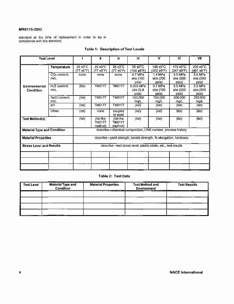
Table 1: Description of Test Levels
Test Level I II III IV V VI VII
Environmental Condition
Temperature 25 ±3°C (77 ±5°F)
25 ±3°C (77 ±5°F)
25 +3°C (77 +5°F)
90 ±5°C (194±9°F)
150 ±5°C (302 ±9°F)
175 +5°C (347 ±9°F)
205 ±5°C (401 ±9°F)
Environmental Condition
CO2 content, min.
none none none 0.7 MPa abs (100
psia)
1.4 MPa abs (200
psia)
3.5 MPa abs (500
psia)
3.5 MPa abs (500
psia) Environmental
Condition H2S content, min.
(list) TM0177 TM0177 0.003 MPa abs (0.4
psia)
0.7 MPa abs (100
psia)
3.5 MPa abs (500
psia)
3.5 MPa abs (500
psia)
Environmental Condition
NaCI content, min.
(list) TM0177 TM0177 150,000 mg/L
150,000 mg/L
200,000 mg/L
250,000 mg/L
Environmental Condition
pH (list) TM0177 TM0177 (list) (list) (list) (list)
Environmental Condition
Other (list) none coupled to steel
(list) (list) (list) (list)
Test Method(s) (list) (list the TM0177 method)
(list the TM0177 method)
(list) (list) (list) (list)
Material Type and Condition describe—chemical composition, UNS number, process history
Material Properties describe—yield strength, tensile strength, % elongation, hardness
Stress Level and Results describe—test stress level, plastic strain, etc., test results
Table 2: Test Data
Test Level Material Type and Condition
Material Properties Test Method and Environment
Test Results
4 NACE International

MR0175-2002
10 MILLIGRAMS H 2S PER SCM(16°C, 1 atm.)
100 1,000 10,000 100,000
0.1 GRAINS H2S PER 100 SCF(60°F, 1 atm.)
10 100 1,000
—
/% —
X — —
—
SULF] IDE ST RI ES >S Cf lACKir IG F IEC il( 31 =
1.45 MPa abs (65 PSIA) TOTAL PRESSURI E — ( 1.45 MPa abs (65 PSIA) TOTAL PRESSURI E —
— —
10 a a. Z uT eC 3 (A (A
a
1
0.1
0.0001 1
0.001 10
0.01 0.1 100 1,000
MOL % H 2S IN GAS PPM H,S IN GAS
1 10,000
10 100,000
FIGURE 1: Sour Gas Systems (see Paragraph 1.3.1.1)
NACE International 5
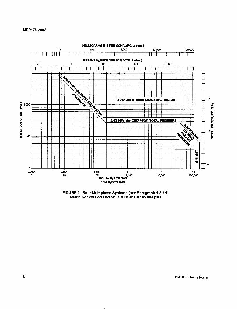
FIGURE 2: Sour Multiphase Systems (see Paragraph 1.3.1.1) Metric Conversion Factor: 1 MPa abs = 145.089 psia
NACE International
MR0175-2002
Section 2: Definitions
Age Hardening: Hardening by aging, usually after rapid cooling or cold working.
Aging: A change in metallurgical properties that generally occurs slowly at room temperature (natural aging) and more rapidly at higher temperature (artificial aging).
Annealing: Heating to and holding at a temperature appropriate for the specific material and then cooling at a suitable rate, for such purposes as reducing hardness, improving machinability, or obtaining desired properties (also see Solution Heat Treatment).
Austenite: The face-centered crystalline phase of iron-base alloys.
Austenitic Steel: A steel whose microstructure at room temperature consists predominantly of austenite.
Austenitizing: Forming austenite by heating a ferrous metal to a temperature in the transformation range (partial austenitizing) or above the transformation range (complete austenitizing).
Autofrettage: A technique whereby residual compressive stresses are created at the interior of a thick-walled component by application and release of internal pressure that causes yielding of the metal near the ID or bore of the component.
Blowout Preventers (BOP): Mechanical devices capable of containing pressure, used for control of well fluids and drilling fluids during drilling operations.
Brazing: Joining metals by flowing a thin layer (of capillary thickness) of a lower-melting-point nonferrous filler metal in the space between them.
Brinell Hardness (HB): A hardness value obtained by use of a 10 mm-diameter hardened steel (or carbide) ball and normally a load of 3,000 kg, in accordance with ASTM E 10.7
Burnishing: Smoothing surfaces with frictional contact between the material and some other hard pieces of material, such as hardened steel balls.
Carbon Steel: An alloy of carbon and iron containing up to 2% carbon and up to 1.65% manganese and residual quantities of other elements, except those intentionally added in specific quantities for deoxidation (usually silicon and/or aluminum). Carbon steels used in the petroleum industry usually contain less than 0.8% carbon.
Case Hardening: Hardening a ferrous alloy so that the outer portion, or case, is made substantially harder than the inner portion, or core. Typical processes are carburizing, cyaniding, carbonitriding, nitriding, induction hardening, and flame hardening.
Cast Component (Casting): Metal that is obtained at or near its finished shape by the solidification of molten metal in a mold.
Cast Iron: An iron-carbon alloy containing approximately 2 to 4% carbon. Cast irons may be classified as:
(1) gray cast iron—cast iron that gives a gray fracture as a result of the presence of flake graphite;
(2) white cast iron—cast iron that gives a white fracture as a result of the presence of cementite (Fe3C);
(3) malleable cast iron—white cast iron that is thermally treated to convert most or all of the cementite to graphite (temper carbon);
(4) ductile (nodular) cast iron—cast iron that has been treated while molten with an element (usually magnesium or cerium) that spheroidizes the graphite; or
(5) austenitic cast iron—cast iron with a sufficient amount of nickel added to produce an austenitic microstructure.
Cemented Tungsten Carbide: Pressed and sintered monolithic tungsten carbide alloys consisting of tungsten carbide with alloy binders of primarily cobalt or nickel.
Chloride Stress Corrosion Cracking: Failure by cracking under the combined action of tensile stress and corrosion in the presence of chlorides and water.
Cold Deforming: See Cold Working.
Cold Forming: See Cold Working.
Cold Reducing: See Cold Working.
Cold Working: Deforming metal plastically under conditions of temperature and strain rate that induce strain hardening, usually, but not necessarily, conducted at room temperature. Contrast with hot working.
Double Tempering: A treatment in which normalized or quench-hardened steel is given two complete tempering cycles (cooling to a suitable temperature after each cycle) with the second tempering cycle performed at a temperature at or below the first tempering temperature. The object is to temper any martensite that may have formed during the first tempering cycle.
Duplex (Austenitic/Ferritic) Stainless Steel: A stainless steel whose microstructure at room temperature consists primarily of a mixture of austenite and ferrite.
NACE International 7

MR0175-2002
Elastic Limit: The maximum stress to which a material may be subjected without any permanent strain remaining upon complete release of stress.
Ferrite: A body-centered cubic crystalline phase of iron-based alloys.
Ferritic Steel: A steel whose microstructure at room temperature consists predominantly of ferrite.
Ferrous Metal: A metal in which the major constituent is iron.
Free-Machining Steel: Steel to which elements such as sulfur, selenium, or lead have been added intentionally to improve machinability.
Hardness: Resistance of metal to plastic deformation, usually by indention.
Heat Treatment: Heating and cooling a solid metal or alloy in such a way as to obtain desired properties. Heating for the sole purpose of hot working is not considered heat treatment. (See also Solution Heat Treatment.)
Heat-Affected Zone (HAZ): That portion of the base metal that was not melted during brazing, cutting, or welding, but whose microstructure and properties were altered by the heat of these processes.
Hot Rolling: Hot working a metal through dies or rolls to obtain a desired shape.
Hot Working: Deforming metal plastically at such a temperature and strain rate that recrystallization takes place simultaneously with the deformation, thus avoiding any strain hardening.
Low-Alloy Steel: Steel with a total alloying element content of less than about 5%, but more than specified for carbon steel.
Lower Critical Temperatures: In ferrous metals, the temperatures at which austenite begins to form during heating or at which the transformation of austenite is completed during cooling.
Manufacturer: The firms or persons involved in some or all phases of manufacturing or assembly of components. For example, the firm used to upset tubing is considered a manufacturer.
Martensite: A supersaturated solid solution of carbon in iron characterized by an acicular (needle-like) microstructure.
Martensitic Steel: A steel in which a microstructure of martensite can be attained by quenching at a cooling rate fast enough to avoid the formation of other microstructures.
Microstructure: The structure of a metal as revealed by microscopic examination of a suitably prepared specimen.
Nitriding: A case-hardening process whereby nitrogen is introduced into the surface of metallic materials (most commonly ferrous alloys). Typical processes include, but are not limited to, liquid nitriding, gas nitriding, and ion or plasma nitriding.
Nonferrous Metal: A metal in which the major constituent is one other than iron.
Normalizing: Heating a ferrous metal to a suitable temperature above the transformation range (austenitizing), holding at temperature for a suitable time, and then cooling in still air or protective atmosphere to a temperature substantially below the transformation range.
Partial Pressure: Ideally, in a mixture of gases, each component exerts the pressure it would exert if present alone at the same temperature in the total volume occupied by the mixture. The partial pressure of each component is equal to the total pressure multiplied by its mole fraction in the mixture. For an ideal gas, the mole fraction is equal to the volume fraction of the component.
Plastic Deformation: Permanent deformation caused by stressing beyond the elastic limit.
Postweld Heat Treatment: Heating and cooling a weldment in such a way as to obtain desired properties.
Precipitation Hardening: Hardening a ferrous metal by austenitizing and then cooling rapidly enough so that some or all of the austenite transforms to martensite.
Pressure-Containing Parts: Those parts whose failure to function as intended would result in a release of retained fluid to the atmosphere. Examples are valve bodies, bonnets, and stems.
Quench and Temper: Quench hardening followed by tempering.
Recrystallization Temperature: The minimum temperature at which a new strain-free structure is produced in cold-worked metal within a specified time.
Residual Stress: Stress present in a component free of external forces or thermal gradients.
Rockwell C Hardness (HRC): A hardness value obtained by use of a cone-shaped diamond indentor and a load of 150 kg, in accordance with ASTM E 18.8
Shot Peening: Inducing compressive stresses in a material's surface layer by bombarding it with a selected medium (usually round steel shot) under controlled conditions.
Slush Pump: Pump normally used to circulate drilling fluids through the drill stem into the annulus of the hole and to the surface for the purpose of removing cuttings and maintaining a hydrostatic head.
8 NACE International
MR0175-2002
Solid Solution: A single crystalline phase containing two or more elements.
Solution Heat Treatment (Solution Anneal): Heating a metal to a suitable temperature and holding at that temperature long enough for one or more constituents to enter into solid solution, then cooling rapidly enough to retain the constituents in solution.
Sour Environment: See Paragraph 1.3.
Stainless Steel: Steel containing 10.5% or more chromium. Other elements may be added to secure special properties.
Standard Cubic Foot of Gas: The quantity of a gas occupying one cubic foot at a pressure of one atmosphere or 0.10133 MPa abs (14.696 psia) and a temperature of 15°C (59°F).
Stress Corrosion Cracking (SCC): Cracking of metal produced by the combined action of corrosion and tensile stress (residual or applied).
Stress Relieving (Thermal): Heating a metal to a suitable temperature, holding at that temperature long enough to reduce residual stresses, and then cooling slowly enough to minimize the development of new residual stresses.
Sulfide Stress Cracking (SSC): Brittle failure by cracking under the combined action of tensile stress and corrosion in the presence of water and H2S. See Paragraph 1.1 for information on blistering.
Surface Hardening: See Case Hardening.
Tempering: In heat treatment, reheating hardened steel or hardened cast iron to some temperature below the lower critical temperature for the purpose of decreasing the hardness and increasing the toughness. The process is also sometimes applied to normalized steel.
Tensile Strength: In tensile testing, the ratio of maximum load to original cross-sectional area (see ASTM A 3709). Also called ultimate strength.
Tensile Stress: The net tensile component of all combined stresses—axial or longitudinal, circumferential or "hoop," and residual.
Transformation Ranges: Those ranges of temperature for steels within which austenite forms during heating and transforms during cooling. The two ranges are distinct, sometimes overlapping, but never coinciding.
Tubular Component: A cylindrical component (pipe) having a longitudinal hole that is used in drilling/production operations for conveying fluids.
Welding: Joining two or more pieces of metal by applying heat and/or pressure with or without filler metal, to produce a union through localized fusion of the substrates and solidification across the interface.
Weldment: That portion of a component on which welding has been performed. A weldment includes the weld metal, the heat-affected zone (HAZ), and the base metal.
Weld Metal: That portion of a weldment that has been molten during welding.
Wrought: Metal in the solid condition that is formed to a desired shape by working (rolling, extruding, forging, etc.), usually at an elevated temperature.
Yield Strength: The stress at which a material exhibits a specified deviation from the proportionality of stress to strain. The deviation is expressed in terms of strain by either the offset method (usually at a strain of 0.2%) or the total-extension-under-load method (usually at a strain of 0.5%) (see ASTM A 370).
Section 3: Ferrous Metals
3.1 General. Ferrous metals shall meet the requirements of this section if they are to be exposed to sour environments. The presence of environmental (H2S partial pressure, sulfur content, chloride content, and temperature) and/or mechanical strength limitations for some corrosion-resistant alloy (CRA) materials does not mean that those materials do not resist stress corrosion cracking as well as those materials in the same class that do not have such limitations.
The susceptibility to SSC of most ferrous metals can be strongly affected by heat treatment, cold work, or both. The following paragraphs describe heat treatments for specific materials that have been found to provide acceptable resistance to SSC.
3.2 Carbon and Low-Alloy Steels
3.2.1 All carbon and low-alloy steels are acceptable at 22 HRC maximum hardness provided they (1) contain less than 1% nickel, (2) meet the criteria of Paragraphs 3.2.2, 3.3, and Section 5, and (3) are used in one ofthe following heat-treat conditions:
(a) hot-rolled (carbon steels only);
(b) annealed;
(c) normalized;
(d) normalized and tempered;
(e) normalized, austenitized, quenched, and tempered; or
N A C E International 9
MR0175-2002
(f) austenitized, quenched, and tempered.
3.2.1.1 Forgings produced in accordance with the requirements of ASTM A 105 1 0 are acceptable, provided the hardness does not exceed 187 HB maximum.
3.2.1.2 Acceptance criteria: Wrought carbon and low-alloy steels with a hardness greater than 22 HRC that are not otherwise covered by this standard must meet the following minimum criteria for balloting prior to inclusion in this standard. These criteria are necessary but may not be sufficient conditions for inclusion in all cases.
(1) The candidate steel must be tested in accordance with the test procedures established in NACE Standard TM0177. The tensile bar, C-ring, bent beam, and double-cantilever beam as described in NACE Standard TM0177 are accepted test specimens. Any of these specimens may be used.
(2) A minimum of three specimens from each of three different commercially prepared heats must be tested in the (heat-treated) condition balloted for MR0175 inclusion. The composition of each heat and the heat treatment(s) used shall be furnished as part of the ballot. The candidate material's composition range and/or UNS number and its heat-treated condition requested for inclusion in MR0175 must be included with the ballot.
(3) The Rockwell hardness of each specimen must be determined and reported as part of the ballot. The average hardness of each specimen shall be the hardness of that specimen. The minimum specimen hardness obtained for a given heat/condition shall be the hardness of that heat/condition for the purpose of balloting. The maximum hardness requested for inclusion ofthe candidate material in MR0175 must be specified in the ballot and should be supported by the data provided.
(4) Further, in order for the material/condition to be considered for acceptance, it is required that, for each of the commercial heats tested, stress intensity values, etc. (as applicable to the test method used), of all tests shall also be reported as part of the ballot item when submitted.
3.2.2 The metal must be thermally stress relieved following any cold deforming by rolling, cold forging, or another manufacturing process that results in a permanent outer fiber deformation greater than 5%. Thermal stress relief shall be performed in accordance with the ASME Code, 1 1 Section VIII, Division 1, except that the minimum stress-relief temperature shall be 595°C (1,100°F). The component shall have a hardness of 22 HRC maximum.
These materials may be subject to chloride stress corrosion cracking
3.2.2.1 This requirement does not apply to pipe grades listed in Table 5 or cold work imparted by pressure testing according to the applicable code. Cold-rotary straightened pipe is acceptable only where permitted in API specifications. Cold-worked line pipe fittings of ASTM A 53 1 2 Grade B, ASTM A 106 1 3 Grade B, API 5L 1 4 Grade X-42, or lower-strength grades with similar chemical compositions are acceptable with cold strain equivalent to 15% or less, provided the hardness in the strained area does not exceed 190 HB.
3.3 Free-Machining Steels
3.3.1 Free-machining steels shall not be used.
3.4 Cast Iron
3.4.1 Gray, austenitic, and white cast irons are not acceptable for use as a pressure-containing member. These materials may be used in internal components related to API and other appropriate standards, provided their use has been approved by the purchaser.
3.4.2 Ferritic ductile iron in accordance with ASTM A 395 1 5 is acceptable for equipment when API, ANSI, and/or other industry standards approve its use.
3.5 Austenitic Stainless Steels 1 1 0 1
3.5.1 Austenitic stainless steels with chemical compositions as specified in accordance with the standards listed in Table 3, either cast or wrought, are acceptable at a hardness of 22 HRC maximum in the annealed condition, provided they are free of cold work designed to enhance their mechanical properties.
3.5.2 Austenitic stainless steel UNS S20910 is acceptable at 35 HRC maximum hardness in the annealed or hot-rolled (hot/cold-worked) condition, provided it is free of subsequent cold work designed to enhance its mechanical properties.
3.5.3 Austenitic stainless steel alloy UNS N08020 is acceptable in the annealed or cold-worked condition at a hardness level of 32 HRC maximum.
3.5.4 Cast CN7M meeting ASTM A 351 , 1 6 A 743, 1 7 or A 744 1 8 is acceptable for nondownhole applications in the following conditions (there are no industry standards that address these melting and casting requirements):
(1) solution-annealed at 1,121°C (2,050°F) minimum or solution-annealed at 1,121°C (2,050°F) minimum and welded with AWS E320LR or ER320LR;
in certain environments.
10 N A C E International

MR0175-2002
(2) the castings must be produced from argon-oxygen decarburization (AOD) refined heats or re-melted AOD refined heats. The use of scraps, such as turnings, chips, and returned materials is prohibited unless melting is followed by AOD refining;
(3) the CN7M composition listed in ASTM A 351, A 743, or A 744 shall be further restricted to 0.03% maximum carbon, 1.00% maximum silicon, 3.0 to 3.5% copper, 0.015% maximum sulfur, 0.030% maximum phosphorus, and 0.05% maximum aluminum; and
(4) at a hardness level of 22 HRC maximum.
3.5.5 Wrought austenitic stainless steel UNS S31254 is acceptable in the annealed or cold-worked condition at a hardness level of 35 HRC maximum.
3.5.6 Solution-annealed and cold-worked austenitic stainless steel UNS N08367 is acceptable at a maximum hardness of 35 HRC for use in sour environments at any temperature up to 150°C (302°F) only if: no free elemental sulfur is present, the salinity is less than 5,000 mg/L, and the H2S partial pressure does not exceed 310 kPa (45 psi).
3.5.7 Wrought UNS S32200 is acceptable in the annealed or annealed plus cold-worked condition at a hardness level of 34 HRC maximum when the service environment is less than 170°C (338°F), contains less than 100 kPa (14.6 psi or 1 bar) H2S, and does not contain elemental sulfur.
3.5.8 Wrought stainless steel UNS N08926 is acceptable in the annealed or cold-worked condition at a hardness level of 35 HRC maximum for use in Environment V according to Paragraph 1.6.2, Table 1. Alloy UNS N08926 has been shown resistant at temperatures up to 121°C (250°F) in sour environments containing 60,700 mg/L chloride (10% NaCI), 0.7 MPa (101.5 psi) H2S, 1.4 MPa (203 psi) C0 2.
3.5.9 Cast UNS J93254 (CK3MCuN) in accordance with ASTM A 351, A 743, or A 744 is acceptable in the cast, solution heat-treated condition at a hardness level of 100 HRB maximum in the absence of elemental sulfur. Test data to Levels II and III in Table 2 were balloted.
Test Material Material Test Method, Test Level Type and Properties Environment Results
Condition II and III UNS YS|A> 300- TM0177 No
J93254 330 MPa (43- solution, 180° failures (CK3MCuN) 48 ksi) UTS (B ) u-bend in 720+ castings, 590-650 MPa loaded h solution (86-94 ksi) beyond yield, heat-treated Elong. 47- iron coupled
54% and non-iron coupled
YS 330-340 TM0177 No MPa (48-50 tensile, failures ksi) UTS 650- loaded to in 720+ 690 MPa (94- yield, iron h 100 ksi) coupled and Elong. 47- non-iron 48% coupled
w Yield strength. | B ) Ultimate tensile strength.
3.5.10.1 UNS N08367 is acceptable in the wrought, solution heat-treated or solution heat-treated and cold-worked condition to 35 HRC maximum in the absence of elemental sulfur. Test data to Levels II, III, and modified V in Table 2 were balloted.
Test Level
Material Type and Condition
Material Properties
Test Method, Environment
Test Results
II and III UNS N08367 solution heat-treated and solution heat-treated and cold-worked
YS 1,300 MPa (120 ksi) UTS 1,400 MPa (200 ksi) Elong. 11-16% Hardness 41-45 HRC
TM0177 Method A loaded to 90% of yield, iron coupled and non-iron coupled
No failures in 720+h
V mod 4-point bent-beam, Level V modified: 10% NaCI, 121°C (302°F), 0.7 MPa abs (100 psia) H2S, at 100% of yield
No failures in 720+h
3.5.11 Wrought UNS S32654 is acceptable in the absence of elemental sulfur, and in the annealed condition at a hardness level of 22 HRC maximum provided that it is free of cold work designed to enhance the mechanical properties. Test data to Levels II and III of Table 1 were balloted.
NACE International 11

MR0175-2002
Test Level
Material Type and Condition
Material Properties Test Method and Environment Test Results
II Wrought, annealed UNS S32654
Hardness up to 16.5 HRC
Four-point loading, 0.9-1.0 x YS, 5% NaCI + 0.5% HAc, R l m
ptot(B! = pH2S = 100 kPa abs (14.5 psia) 12 specimens tested, no cracks
II Wrought, annealed, cold deformed by rolling 40%
Hardness up to 42.5 HRC
Four-point loading, 0.9-1.0 x YS, 5% NaCI + 0.5% HAc, RT ptot = pH2S = 100 kPa abs (14.5 psia)
12 specimens tested, no cracks
III Wrought, annealed Hardness up to 16.5 HRC
Four-point loading, 0.9-1.0 x YS, coupling to carbon steel, 5% NaCI + 0.5% HAc, RT ptot = pH2S = 100 kPa abs (14.5 psia)
12 specimens tested, no cracks
III Wrought, annealed, cold deformed by rolling 40%
Hardness up to 42.5 HRC
Four-point loading, 0.9-1.0 x YS, coupling to carbon steel, 5% NaCI + 0.5% HAc, RT Ptot = pH2S = 100 kPa abs (14.5 psia)
12 specimens tested, no cracks
Room temperature. Total pressure.
3.5.12 Wrought UNS S31266 processed with vacuum subsequently solution annealed and cold worked is induction melting (VIM) or vacuum oxygen deoxidation acceptable to 38 HRC maximum hardness for use up (VOD) followed by electroslag remelting (ESR) and to Environment V according to Paragraph 1.6.2, Table
1. Test data to Levels I and V were balloted.
Test Level
Material Type and Condition
Material Properties
Test Method and Environment Stress Level (% Actual Y.S.)
Test Results
I Solution-annealed and cold-drawn UNS S31266
41 HRC TM0177 Method A— 5% NaCI 0.5% acetic acid 0.10 MPa abs (15 psia) H2S 24°C (75°F)
100 720 h No failures
I Solution-annealed and cold-drawn
41 HRC TM0177 Method A — 5% NaCI 0.5% acetic acid 0.10 MPa abs (15 psia) H2S 24°C (75°F) coupled to steel
100 720 h No failures
I Solution-annealed and cold-worked by tensile straining
37, 36, 35 HRC
TM0177 Method A — 5% NaCI 0.5% acetic acid 0.10 MPa abs (15 psia) H2S 24°C (75°F)
100 720 h No failures
I Solution-annealed and cold-worked by tensile straining
37, 36, 35 HRC
TM0177MethodA — 5% NaCI 0.5% acetic acid 0.10 MPa abs (15 psia) H2S 24°C (75°F)
100 720 h No failures
V Solution-annealed and cold-drawn
41 HRC TM0177 Method A — 15% NaCI 0.7 MPa abs (100 psia) H2S 1.4 MPa abs (200 psia) C0 2
150°C (302°F)
90 at 150°C (302°F)
720 h No failures
V Solution-annealed and cold-worked by tensile straining
37, 38 HRC TM0177 Method A — 15% NaCI 0.7 MPa abs (100 psia) H2S 1.4 MPa abs (200 psia) C0 2
150°C (302°F)
90at150°C (302°F)
720 h No failures
V mod. l A | Solution-annealed and cold-rolled
38, 39 HRC Four-point bend test — 20% NaCI 0.7 MPa abs (100 psia) H2S 1.4 MPa abs (200 psia) C0 2
150°C (302°F)
100 at 150°C (302°F)
720 h No failures
mod. — 20% NaCI was used instead of the standard 15% NaCI as given in the normal Level V test solution.
12 NACE International

MR0175-2002
3.5.13 Wrought UNS S34565 is acceptable in the solution-annealed condition to 29 HRC maximum in the absence of elemental sulfur. Test data to Level IV in Table 1 were balloted. Level III testing was done with coupling to carbon steel.
Test Level
Material Type and
Condition
Material Properties
Test Method and
Environment
Stress Level
Test Results
III Wrought, solution-annealed UNS S34565
Max. 29 HRC
TM0177, Solution A, RT, Method A
90% YS
No failures
IV Wrought, solution-annealed UNS S34565
Max. 29 HRC
TM0177, Table 1 Level IV, 90°C (194°F), Method A
90% SMYS
No failures
IV Wrought, solution-annealed UNS S34565
Max. 29 HRC
Similar to TM0198, 90°C (194°F)
No cracks
3.6 Ferritic Stainless Steels
3.6.1 Ferritic stainless steels are acceptable at a 22 HRC maximum hardness, provided they are in the annealed condition and meet the criteria of Section 5. Acceptable ferritic stainless steels are listed in Table 3.
3.7 Martensitic Stainless Steels' 1 1 '
3.7.1 Martensitic stainless steels, as listed in Table 3, either cast or wrought, are acceptable at 22 HRC maximum hardness provided they are heat treated in accordance with Paragraph 3.7.1.1 and meet the criteria of Section 5. Martensitic stainless steels that are in accordance with this standard have provided satisfactory field service in some sour environments. These materials may, however, exhibit threshold stress levels in NACE Standard TM0177 that are lower than those for other materials included in this standard.
3.7.1.1 Heat Process)
Treat Procedure (Three-Step
(1) Normalize or austenitize and quench.
(2) Temper at 620°C (1,150°F) minimum; then cool to ambient temperature.
(3) Temper at 620°C (1,150°F) minimum, but lower than the first tempering temperature; then cool to ambient temperature.
3.7.1.2 Subsequent to cold deformation (see Paragraph 3.2.2) the material shall be furnace stress relieved at 620°C (1,150°F) minimum to 22 HRC maximum hardness.
3.7.2 Low-Carbon Martensitic Stainless Steels
3.7.2.1 Cast and wrought low-carbon martensitic stainless steels meeting the chemistry requirements of ASTM A 487 Grade CA6NM and UNS S42400 are acceptable to 23 HRC maximum provided they are heat treated in accordance with Paragraph 3.7.2.1.1.'"" (12)
3.7.2.1.1 Heat-Treat Procedure (Three-Step Process)
(1) Austenitize at 1,010°C (1,850°F) minimum and air or oil quench to ambient temperature.
(2) Temper at 648° to 690°C (1,200° to 1,275°F) and air cool to ambient temperature.
(3) Temper at 593° to 620°C (1,100° to 1,150°F) and air cool to ambient temperature.
3.7.2.2 Wrought low-carbon martensitic stainless steel UNS S41425 is acceptable in the austenitized, quenched, and tempered condition to 28 HRC maximum hardness in the absence of elemental sulfur. Test data to Level I in Table 1 were balloted.
Level Material Type and Condition
Material Properties
Test Method and
Environment
Stress Level
Test Results
I Wrought, quenched, and tempered UNS S41425
29, 27, 28 HRC
TM0177 Solution A except H2S 0.010 MPa abs (1.5 psia) pH 3.5 RT Method A Uncoupled to steel
80% SMYS
No failures
I Wrought, quenched, and tempered
29, 27, 28, 29 HRC
H2S 0.0030 MPa (0.45 psia) C0 2 0.7 MPa abs (101 psia) NaCI 15% Temp. 90°C (194°F)
80% and 90% SMYS
No failures
I Wrought, quenched, and tempered
29, 27, 28 HRC
H2S 0.010 MPa (1.5 psia) COj 20 MPa abs (450 psia) NaCI 5% Temp. 175°C (348°F)
80% and 90% SMYS
No failures
Valve manufacturers generally do not use these materials for valve stems or other highly stressed components in sour service. ( 1 2 ' The hardness correlation tabulated in ASTM E 140 does not apply to CA6NM or UNS S42400. When hardness is measured in Brinell units, the permissible BHN limit is 255 maximum, which has been empirically determined to be equivalent to 23 HRC for these alloys.
N A C E International 13
MR0175-2002
3.8 Precipitation-Hardening Stainless Steels' '
3.8.1 Wrought UNS S17400 martensitic precipitation-hardening stainless steel is acceptable at 33 HRC maximum hardness provided it has been heat treated in accordance with Paragraph 3.8.1.1 or Paragraph 3.8.1.2. Precipitation-hardening martensitic stainless steels that are in accordance with this standard have provided satisfactory field service in some sour environments. These materials may, however, exhibit threshold stress levels in NACE Standard TM0177 that are lower than those of other materials included in this standard.
3.8.1.1 Double Age at 620°C (1,150°F)
(1) Solution anneal at 1,040° ±14°C (1,900° ±25°F) and air cool, or suitable liquid quench, to below 32°C (90°F).
(2) Harden at 620° ±14°C (1,150° ±25°F) for 4 hours minimum at temperature and cool in air.
(3) Cool material to below 32°C (90°F) before the second precipitation-hardening step.
(4) Harden at 620° ±14°C (1,150° ±25°F) for 4 hours minimum at temperature and cool in air.
3.8.1.2 Heat-Treat Procedure (Three-Step Process)
(1) Solution anneal at 1,040° ±14°C (1,900° ±25°F) and air cool, or suitable liquid quench, to below 32°C (90°F).
(2) Harden at 760° ±14°C (1,400° ±25°F) for 2 hours minimum at temperature and cool in air to below 32°C (90°F) before second precipitation-hardening step.
(3) Precipitation harden at 620° ±14°C (1,150° ±25°F) for 4 hours minimum at temperature and cool in air.
3.8.2 Austenitic precipitation-hardening stainless steel with chemical composition in accordance with UNS S66286 is acceptable at 35 HRC maximum hardness provided it is in either the solution-annealed and aged or solution-annealed and double-aged condition.
3.8.3 Wrought UNS S45000 martensitic precipitation-hardening stainless steel is acceptable at 31 HRC maximum hardness provided it has been heat treated in accordance with Paragraph 3.8.3.1.
3.8.3.1 Heat-Treat Procedure (Two-Step Process)
(1) Solution anneal.
(2) Precipitation harden at 620°C (1,150°F) minimum for 4 hours.
3.9 Duplex Stainless Steels'101
3.9.1 The wrought duplex (austenitic/ferritic) stainless steels listed in Table 3 are acceptable at 28 HRC maximum in the solution-annealed condition.
3.9.2 The cast duplex (austenitic/ferritic) stainless steel Z 6 CNDU 28.08 M, NF A 320-5520 French National Standard is acceptable at hardness levels of 17 HRC maximum in the annealed and quenched condition provided the ferrite content is 25 to 40%. The annealing shall be at a temperature of 1,150° ±10°C (2,100° +20°F) and shall be followed by a rapid quench to avoid the precipitation of sigma phase.
3.9.3 Wrought duplex stainless steel UNS S32404 (0.1% to 0.2% nitrogen) is acceptable at 20 HRC maximum in the solution-annealed condition.
3.9.4 Solution-annealed and cold-worked UNS S31803 is acceptable for use at any temperature up to 232°C (450°F) in sour environments if the partial pressure of H2S does not exceed 0.002 MPa abs (0.3 psia), the yield strength of the material is not greater than 1,100 MPa (160 ksi), and its hardness is not greater than 36 HRC.
3.9.5 Wrought duplex stainless steel UNS S32750 is acceptable at 32 HRC maximum in the solution-annealed condition in sour environments up to 232°C (450°F) if the H2S partial pressure does not exceed 0.01 MPa abs (1.5 psia).
3.9.6 Wrought duplex stainless steel UNS S32760 is acceptable in the solution-annealed and cold-worked condition at a maximum hardness of 34 HRC for use in sour environments containing up to 120,000 mg/L chloride ion if the partial pressure of H2S does not exceed 0.020 MPa (3.0 psi). If the chloride ion concentration is always less than 15,000 mg/L and the pH of the aqueous phase is always greater than 5.6, then this material condition is acceptable if the partial pressure of H2S does not exceed 0.10 MPa (15 psi).
3.9.7 Cast duplex stainless steel UNS J93380 is acceptable in the solution-annealed and quenched condition at a maximum hardness of 24 HRC for use in sour environments containing up to 120,000 mg/L chloride ion if the partial pressure of H2S does not exceed 0.020 MPa (3.0 psi). If the chloride ion concentration is always less than 15,000 mg/L and the pH of the aqueous phase is always greater than 5.6, then this material is acceptable if the partial pressure of H2S does not exceed 0.10 MPa (15 psi).
3.9.8 Wrought UNS S31260 is acceptable in the solution-annealed and cold-worked condition for use to 232°C (450°F) in sour service if the partial pressure of H2S does not exceed 7 kPa (1.0 psi), if the service
14 NACE International
MR0175-2002
environment does not contain elemental sulfur, if the yield strength of the material is 1,100 MPa (160 ksi) maximum, and if the hardness is 36 HRC maximum.
3.9.9 Wrought UNS S39274 is acceptable in the solution-annealed and cold-worked condition for use to 232°C (450°F) in sour service if the partial pressure of H2S does not exceed 10 kPa (1.5 psi), if the service environment does not contain elemental sulfur, if the yield strength of the material is 1,100 MPa (160 ksi) maximum, and if its hardness is 36 HRC maximum.
3.9.10 Cast duplex stainless steel UNS J93404 is acceptable in the annealed and quenched condition to
265 HB maximum to an H2S partial pressure of 10 kPa (1.5 psi) maximum at 110°C (230°F) maximum.
3.9.11 Wrought duplex stainless steel UNS S39277 is acceptable in the solution-annealed condition to 28 HRC maximum for use in sour environments having no elemental sulfur and containing 91,000 mg/L maximum chloride ion if the partial pressure of H2S does not exceed 0.020 MPa (3 psi) maximum. If the pH of the aqueous phase is always greater than 4.5, then this material is acceptable for use in sour environments containing 91,000 mg/L maximum chloride ion if the partial pressure of H 2S does not exceed 0.070 MPa (10 psi) maximum.
Section 4: Nonferrous Metals (13-15)
4.1 General. Nonferrous metals referenced in this section and meeting the stated requirements for both condition and hardness are acceptable for use in sour environments. The presence of environmental (H 2S partial pressure, sulfur content, chloride content, and temperature) and/or mechanical strength limitations for some corrosion-resistant alloy (CRA) materials does not mean that those materials do not resist stress corrosion cracking as well as those materials in the same class that do not have such limitations. See also Table 4.
4.1.1 Nickel-Copper Alloys
4.1.1.1 UNS N04400, ASTM A 494 2 1 Grades M-35-1 and M-35-2, and UNS N04405 are acceptable to 35 HRC maximum.
4.1.1.2 UNS N05500 is acceptable to 35 HRC maximum in each ofthe three following conditions: (1) hot-worked and age-hardened; (2) solution-annealed; and (3) solution-annealed and age-hardened.
4.1.2 Nickel-lron-Chromium Alloys
4.1.2.1 UNS N08800 is acceptable to 35 HRC maximum.
4.1.3 Nickel-Iron-Chromium-Molybdenum Alloys
4.1.3.2 UNS N09925 is acceptable in each of the five following conditions: (1) cold-worked to 35 HRC maximum; (2) solution-annealed to 35 HRC maximum; (3) solution-annealed and aged to 38 HRC maximum; (4) cold-worked and aged to 40 HRC maximum; and (5) hot-finished and aged to 40 HRC maximum.
4.1.3.2.1 Cast UNS N09925 is acceptable, in the absence of elemental sulfur, in the solution-annealed and aged condition to 35 HRC maximum.
4.1.3.3 UNS N08024 is acceptable to 32 HRC maximum.
4.1.3.4 UNS N08028 is acceptable in the solution-annealed and cold-worked condition to 33 HRC maximum.
4.1.3.5 Nickel - iron - chromium - molybdenum -tungsten alloy UNS N06030 is acceptable in the solution-annealed or solution-annealed plus cold-worked condition to a maximum hardness of 41 HRC.
4.1.3.6 UNS N07048 is acceptable in the solution-annealed, solution-annealed and aged, or direct-aged condition to 40 HRC maximum.
4.1.3.1 UNS N08825, UNS N06007, wrought UNS N06250, wrought UNS N06255, and wrought UNS N06975 are acceptable to 35 HRC maximum; UNS N06950 is acceptable to 38 HRC maximum; and UNS N06985 is acceptable to 39 HRC maximum.
4.1.3.7 Wrought UNS N07773 is acceptable in the solution-annealed and aged condition to 40 HRC maximum when the service environment does not contain elemental sulfur, and approved up to 149°C (300°F) in the presence of elemental sulfur.
1 ' These materials may be subject to SSC failure when highly stressed and exposed to sour environments or some well-stimulating acids either with or without inhibitors. ( 1 4 ) Some of the materials in the wrought condition may be susceptible to failure by hydrogen embrittlement when strengthened by cold work and stressed in the transverse direction. <15,Plastic deformation in service may increase the SSC susceptibility of these alloys.
N A C E International 15
MR0175-2002
4.1.3.8 Wrought UNS N09777 is acceptable in the solution-annealed and aged condition to 40 HRC maximum when the service environment does not contain elemental sulfur, and approved up to 121°C (250°F) in the presence of elemental sulfur.
4.1.3.9 UNS N08535 is acceptable in the solution-annealed and cold-worked condition to 35 HRC maximum.
4.1.3.10 Wrought UNS N08042 is acceptable in the solution-annealed or solution-annealed plus cold-worked condition to 31 HRC maximum when the service environment does not contain elemental sulfur.
4.1.3.11 UNS N06952 is acceptable in the solution-annealed or solution-annealed plus cold-worked condition to 35 HRC maximum when the service environment does not contain elemental sulfur.
4.1.3.12 Cast UNS N08826 is acceptable to 87 HRB maximum when solution-annealed and followed by a thermal stabilization anneal for use in sour environments without elemental sulfur. Cast UNS N08826 is acceptable to 87 HRB for use in sour environments with elemental sulfur up to121°C (250° F).
4.1.3.13 Wrought UNS N08032 is acceptable in the solution-annealed or solution-annealed plus cold-worked condition to 27 HRC maximum when the service environment is less than 150°C (302°F) and does not contain elemental sulfur.
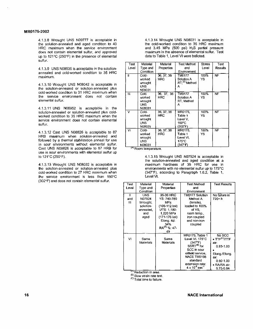
4.1.3.14 Wrought UNS N08031 is acceptable in the cold-worked condition to 35 HRC maximum and 3.45 MPa (500 psi) H 2S partial pressure maximum in the absence of elemental sulfur. Test data to Table 1, Level VI were balloted.
Test Material Material Test Method Stress Test Level Type and
Condition Properties and
Environment Level Results
II Cold- 36, 37, 36 TM0177 100% NF worked HRC Solution A YS wrought RT, (A ) Method UNS A N08031
III Cold 36, 37, 36 TM0177 100% NF worked HRC Solution A YS wrought UNS
RT, Method A
N08031 V Cold- 36, 37, 36 MR0175, 100% NF
worked HRC Table 1 YS wrought UNS
Level V, 150°C
N08031 (300°F) VI Cold- 36, 37, 36 MR0175, 100% NF
worked HRC Table 1 YS wrought UNS
Level VI, 175°C
N08031 (347°F) Room temperature.
4.1.3.15 Wrought UNS N07924 is acceptable in the solution-annealed and aged condition at a maximum hardness of 35 HRC for use in environments with no elemental sulfur up to 175°C (347°F), according to Paragraph 1.6.2, Table 1, Level VI.
Test Material Material Test Method Test Results Level Type and
Condition Properties and
Environment II UNS 35-36 HRC TM0177 Solution No failure in
and N07924 YS: 740-780 Method A 720+h III Wrought,
solution-MPa
(106-112 ksi) (tensile),
loaded to 100% annealed, UTS: 1,180- of YS,
and 1,220 MPa room temp., aged (171-176 ksi)
Elong. 4d: 34%
RA ( A ) %: 47-49
iron coupled and non-iron
coupled
MR0175, Table 1 No SCC VI Same Same Level VI, 175°C . TTF{C)/TTF
Materials Materials (347°F) SSRT(B) for SCC in sour
oilfield service, NACE TM0198
standard extension rate: 4x10"6sec"1
air: 0.93-1.03
• Elong./Elong. air:
0.92-1.00 • RA/RA air:
0.75-0.84 Reduction in area. Slow strain rate test. Total time to failure.
16 N A C E International

MR0175-2002
4.1.3.16 Wrought UNS R20033 is acceptable in the annealed or annealed and cold-worked condition to 35 HRC maximum in the absence of elemental sulfur. Test data to Levels II, III, and IV in Table 1 were balloted.
Test Level
Material Type and Condition
Material Propertie
s
Test Method and Environment
Stress Level
Test Results
II UNS R20033, cold-worked bar
Hardness 40 HRC
TM0177 Method A Solution A, RT
100% YS
No failure
III UNS R20033, cold-worked bar
Hardness 40 HRC
TM0177 Method A Solution A, RT
100% YS
No failure
IV UNS R20033, cold-worked bar
Hardness 35 HRC
TM0177 Method A MR0175, Table 1 Level IV, 90°C (194°F)
100% YS
No failure
4.1.4 Nickel-Chromium Alloys
4.1.4.1 UNS N06600 is acceptable to 35 HRC maximum.
4.1.4.2 UNS N07750 is acceptable to 35 HRC maximum in each of the four following conditions: (1) solution-annealed and aged; (2) solution-annealed; (3) hot-worked; and (4) hot-worked and aged.
4.1.5 Nickel-Chromium-Molybdenum Alloys
4.1.5.1 UNS N06002 and UNS acceptable to 35 HRC maximum.
N06625 are
4.1.5.2 UNS N10002, UNS N10276, ASTM A 494 Grade CW-12 MW, and UNS N06059 are acceptable in the solution-annealed or solution-annealed plus cold-worked condition to 35 HRC maximum.
4.1.5.2.1 Wrought alloys UNS N06022 and UNS N06686 are acceptable in the solution-annealed or solution-annealed plus cold-worked condition to 40 HRC maximum.
4.1.5.2.2 Alloy UNS N10276 is also acceptable in the cold-worked and unaged condition at 45 HRC maximum when used at a minimum temperature of 121°C (250°F).
4.1.5.3 Wrought UNS N07718 is acceptable in each of the five following conditions: (1) solution-annealed to 35 HRC maximum; (2) hot-worked to 35 HRC maximum; (3) hot-worked and aged to 35 HRC maximum; (4) solution-annealed and aged to 40 HRC maximum; and (5) cast, solution-annealed, and aged condition to 40 HRC maximum.
4.1.5.4 UNS N07031 is acceptable in each of the two following conditions: (1) solution-annealed condition to 35 HRC maximum, and (2) solution-annealed and aged at 760° to 870°C (1,400° to 1,600°F) for a maximum of 4 hours to 40 HRC maximum.
4.1.5.5 UNS N06110 and wrought UNS N06060 are acceptable in the annealed or cold-worked condition to 40 HRC maximum.
4.1.5.6 UNS N07716 and wrought UNS N07725 are acceptable to 40 HRC maximum in the solution-annealed and aged condition.
4.1.5.6.1 Wrought UNS N07725 is acceptable in the solution-annealed and aged condition at a hardness level of 43 HRC maximum in the absence of elemental sulfur. Test data to Levels III and VI in Table 2 were balloted.
Test Material Material Test Method, Test Level Type and Properties Environment Results
Condition III UNS YS 1,030-1,100 TM0177 Method No
N07725, MPa (149-160 A, tensile test at failures solution- ksi) 100%ofYS, in 720 h annealed UTS 1,350- coupled to steel, and aged 1,390 MPa environment of
(196-202 ksi) Test Level III in Elong. 23-25% Table 1,25°C RA 33-46% (77°F)
VI UNS YS 1,030-1,100 TM0198 SSRT, No N07725, MPa (149-160 environment of failures, solution- ksi) Test Level VI in SSR (A)
annealed UTS 1,350- Table 1, 175°C ratios and aged 1,390 MPa (347°F) 0.82-
(196-202 ksi) (347°F)
1.16, Elong. 23-25% normal RA 33-46% ductile
behavior ' Slow strain rate.
4.1.5.7 UNS N07626, totally dense hot compacted by a powder metallurgy process, is acceptable in the solution-annealed (925°C [1,700°F] minimum) plus aged condition (525° to 825°C [1,000° to 1,500°F]) or the direct-aged (525° to 825°C [1,000° to 1,500°F]) condition to a maximum hardness of 40 HRC and a maximum tensile strength of 1,380 MPa (200 ksi).
4.1.5.8 Cast CW2M meeting ASTM A 494 is acceptable for nondownhole applications in the following conditions (there are no industry standards that currently address these melting and casting requirements):
(1) solution-annealed at 1,232° ±14°C (2,250° ±25°F) or solution-annealed at 1,232° ±14°C (2,250° ±25°F) and welded with AWS ENiCrMo-7, ERNiCrMo-7, ENiCrMo-10, or ERNiCrMo-10;
N A C E International 17
MR0175-2002
remelted AOD refined heats, or virgin remelt stock. The use of scrap, such as turnings, chips, and returned material is prohibited unless followed by AOD refining;
(3) the CW2M composition listed in ASTM A 494 shall be further restricted to 0.015% maximum sulfur and 0.05% maximum aluminum; and
(4) at a hardness level of 22 HRC maximum.
4.1.5.9 UNS N08135 is acceptable in the solution-annealed and cold-worked condition to a maximum of 33 HRC when the service environment does not contain elemental sulfur or to 137°C (250°F) maximum in the presence of elemental sulfur.
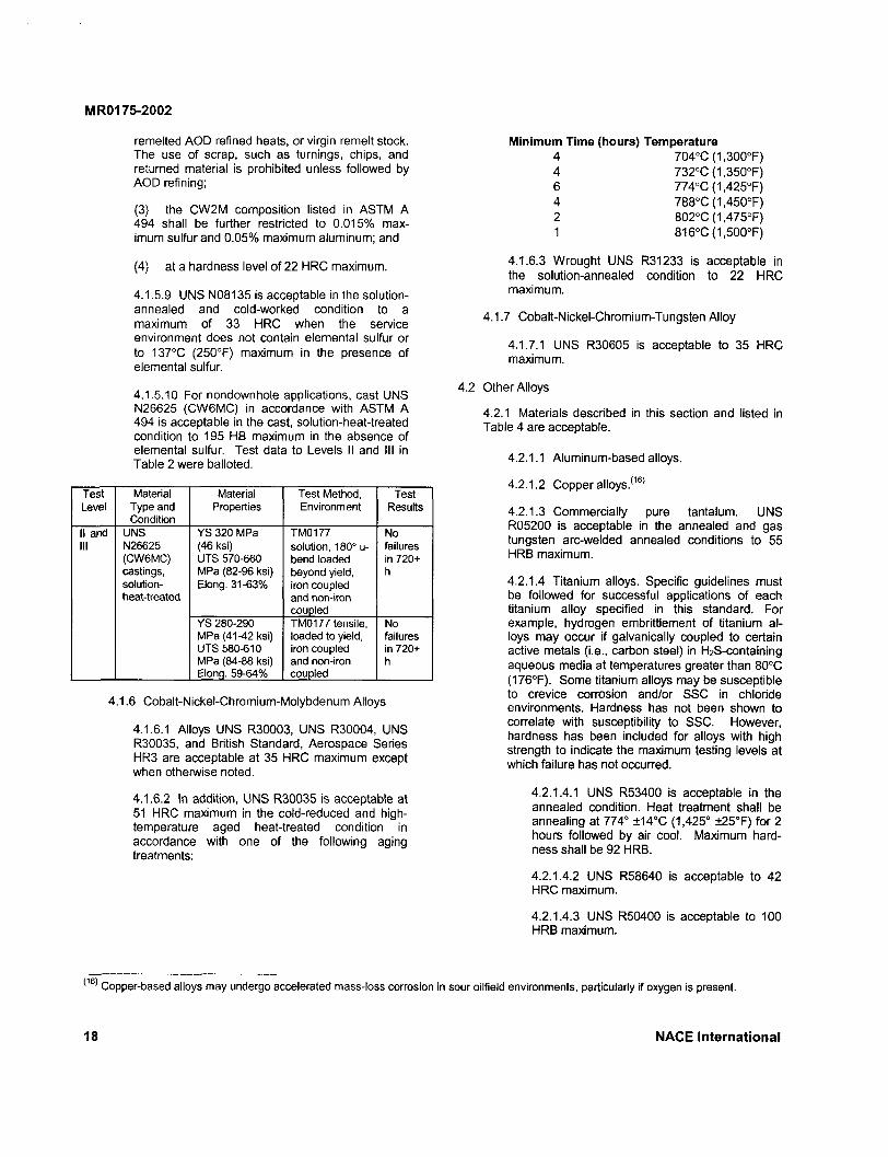
4.1.5.10 For nondownhole applications, cast UNS N26625 (CW6MC) in accordance with ASTM A 494 is acceptable in the cast, solution-heat-treated condition to 195 HB maximum in the absence of elemental sulfur. Test data to Levels II and III in Table 2 were balloted.
Test Level
Material Type and Condition
Material Properties
Test Method, Environment
Test Results
II and III
UNS N26625 (CW6MC) castings, solution-heat-treated
YS 320 MPa (46 ksi) UTS 570-660 MPa (82-96 ksi) Elong. 31-63%
TM0177 solution, 180° u-bend loaded beyond yield, iron coupled and non-iron coupled
No failures in 720+ h
II and III
UNS N26625 (CW6MC) castings, solution-heat-treated
YS 280-290 MPa (4"M2 ksi) UTS 580-610 MPa (84-88 ksi) Elong. 59-64%
TM0177 tensile, loaded to yield, iron coupled and non-iron coupled
No failures in 720+ h
4.1.6 Cobalt-Nickel-Chromium-Molybdenum Alloys
4.1.6.1 Alloys UNS R30003, UNS R30004, UNS R30035, and British Standard, Aerospace Series HR3 are acceptable at 35 HRC maximum except when otherwise noted.
4.1.6.2 In addition, UNS R30035 is acceptable at 51 HRC maximum in the cold-reduced and high-temperature aged heat-treated condition in accordance with one of the following aging treatments:
Copper-based alloys may undergo accelerated mass-loss corrosion i
Minimum Time (hours) Temperature 4 704°C(1,300°F) 4 732°C(1,350°F) 6 774°C(1,425°F) 4 788°C(1,450°F) 2 802°C(1,475°F) 1 816°C(1,500°F)
4.1.6.3 Wrought UNS R31233 is acceptable in the solution-annealed condition to 22 HRC maximum.
4.1.7 Cobalt-Nickel-Chromium-Tungsten Alloy
4.1.7.1 UNS R30605 is acceptable to 35 HRC maximum.
4.2 Other Alloys
4.2.1 Materials described in this section and listed in Table 4 are acceptable.
4.2.1.1 Aluminum-based alloys.
4.2.1.2 Copper alloys. ( 1 6 >
4.2.1.3 Commercially pure tantalum. UNS R05200 is acceptable in the annealed and gas tungsten arc-welded annealed conditions to 55 HRB maximum.
4.2.1.4 Titanium alloys. Specific guidelines must be followed for successful applications of each titanium alloy specified in this standard. For example, hydrogen embrittlement of titanium alloys may occur if galvanically coupled to certain active metals (i.e., carbon steel) in H2S-containing aqueous media at temperatures greater than 80°C (176°F). Some titanium alloys may be susceptible to crevice corrosion and/or SSC in chloride environments. Hardness has not been shown to correlate with susceptibility to SSC. However, hardness has been included for alloys with high strength to indicate the maximum testing levels at which failure has not occurred.
4.2.1.4.1 UNS R53400 is acceptable in the annealed condition. Heat treatment shall be annealing at 774° ±14°C (1,425° ±25°F) for 2 hours followed by air cool. Maximum hardness shall be 92 HRB.
4.2.1.4.2 UNS R58640 is acceptable to 42 HRC maximum.
4.2.1.4.3 UNS R50400 is acceptable to 100 HRB maximum.
sour oilfield environments, particularly if oxygen is present.
18 N A C E International
MR0175-2002
4.2.1.4.4 UNS R56260 is acceptable to 45 HRC maximum in each of the three following conditions: (1) annealed; (2) solution-annealed; and (3) solution-annealed and aged.
4.2.1.4.5 Wrought UNS R56403 is acceptable in the annealed condition to 36 HRC maximum.
4.2.1.4.6 UNS R56404 is acceptable to 35 HRC maximum in the annealed condition.
4.2.1.4.7 UNS R56323 is acceptable to 32 HRC maximum in the annealed condition.
Section 5:
5.1 General. Materials and fabrication processes shall meet the requirements of this section if the material is to be exposed to sour environments.
5.2 Overlays
5.2.1 Overlays applied to carbon and low-alloy steel or to martensitic stainless steels by thermal processes such as welding, silver brazing, or spray metallizing systems are satisfactory for use in sour environments, provided the substrate does not exceed the lower critical temperature during application. In those cases in which the lower critical temperatures are exceeded, the component must be heat treated or thermally stress relieved in accordance with procedures that have been shown to return the base metal to 22 HRC maximum.
5.2.2 Tungsten-carbide alloys and ceramics are satisfactory, subject to the conditions of Paragraph 5.2.1.
5.2.3 Joining of dissimilar materials, such as cemented carbides to alloy steels by silver brazing, is acceptable. The base metal after brazing shall meet the requirements of Paragraph 5.2.1
5.2.4 The materials listed in Sections 3 and 4 are acceptable as weld overlays, provided they meet the provisions of Paragraph 5.2.1.
5.2.5 Overlays of cobalt-chromium-tungsten alloys, nickel-chromium-boron, and nickel-boron (as specified in AMS 4779 2 2) hardfacing alloys are acceptable, subject to the conditions of Paragraph 5.2.1.
5.3 Welding
5.3.1 Welding procedures shall be used to produce weldments that comply with the hardness requirements specified for the base metal in Sections 3 and 4. Welding procedures shall be qualified in accordance with AWS, API, ASME, or other appropriate industry codes. Welders using this procedure shall be familiar with the procedure and shall be capable of making welds that comply with the procedure.
Fabrication
5.3.1.1 Tubular products listed in Table 5 with specified minimum yield strength of 360 MPa (52 ksi) or less and pressure vessel steels classified as P-No 1, Group 1 or 2, in Section 9 ofthe ASME Code and listed in Table 5 meet the requirements of Paragraph 5.3.1 in the as-welded condition. Welding procedure qualifications, in accordance with AWS, API, ASME, or other appropriate specifications, shall be performed on any welding procedure that is used.
5.3.1.2 Welding procedure qualifications on carbon steels that use controls other than thermal stress relieving to control the hardness of the weldment shall also include a hardness traverse across the weld, HAZ, and base metal to ensure that the procedure is capable of producing a hardness of 22 HRC maximum in the condition in which it is used.
5.3.1.3 Low-alloy steel and martensitic stainless steel weldments shall be stress relieved at a minimum temperature of 620°C (1,150°F) to produce a hardness of 22 HRC maximum.
5.3.2 Welding rods, electrodes, fluxes, filler metals, and carbon and low-alloy steel welding consumables with more than 1% nickel shall not be used for welding carbon and low-alloy steels as indicated in Paragraph 3.2.1.
5.4 Identification Stamping
5.4.1 Identification stamping using low-stress (dot, vibratory, and round V) stamps is acceptable.
5.4.2 Conventional sharp V stamping is acceptable in low-stress areas, such as the outside diameter of flanges. Sharp V stamping is not permitted in high-stress areas unless subsequently stress relieved at 595°C (1,100°F) minimum.
5.5 Threading
5.5.1 Machine-Cut Threads
5.5.1.1 Machine-cut threading processes are acceptable.
N A C E International 19
MR0175-2002
5.5.2 Cold-Formed (Rolled) Threads
5.5.2.1 Subsequent to cold forming threads, the threaded component shall meet the heat-treat conditions and hardness requirements given in either Section 3 or 4 for the parent alloy from which the threaded component was fabricated.
5.6 Cold-Deformation Processes
5.6.1 Cold-deformation processes such as burnishing that do not impart cold work exceeding that incidental
to normal machining operations, such as turning or boring, rolling, threading, drilling, etc., are acceptable.
5.6.2 Cold deformation by controlled shot peening is permitted when applied to base materials that meet the requirements of this standard and when limited to the use of a maximum shot size of 2.0 mm (0.080 in.) and a maximum of 10C Almen intensity. The process shall be controlled in accordance with Military Specification MIL-S-13165.23
Section 6:
6.1 General. Materials shall meet the requirements of this section if they are to be exposed to sour environments.
6.2 Exposed Bolting
6.2.1 Bolting that will be exposed directly to the sour environment or that will be buried, insulated, equipped with flange protectors, or otherwise denied direct atmospheric exposure must be as described in Paragraphs 6.2.1.1, 6.2.1.2, or 6.2.1.3. Designers and users should be aware that it may be necessary to derate the pressure rating in some cases when using low-strength bolts. For API 6A24
flanges using exposed bolting, see API Spec 6A.
6.2.1.1 Acceptable nuts and bolting materials shall meet the requirements of Section 3 or Section 4.
Bolting
6.2.1.2 Bolting materials that meet the specifications of ASTM A 19325 Grade B7M, 550 MPa (80,000 psi) minimum yield strength, and 22 HRC maximum are acceptable.
6.2.1.3 Nuts shall meet the specifications of ASTM A 19426 Grade 2HM (22 HRC maximum) or Paragraph 6.2.1.1.
6.3 Nonexposed Bolting
6.3.1 Bolting that is not directly exposed to sour environments and is not to be buried, insulated, equipped with flange protectors, or otherwise denied direct atmospheric exposure may be furnished to applicable standards such as ASTM A 193 Grade B7.
Section 7: Platings and Coatings
7.1 General. Materials shall meet the requirements of this section if they are to be exposed to sour environments.
7.1.1 Metallic coatings (electroplated or electroless), conversion coatings, and plastic coatings or linings are not acceptable for preventing SSC of base metals. The use of such coatings for other purposes is outside the scope of this standard.
7.2 Nitriding
7.2.1 Nitriding with a maximum case depth of 0.15 mm (0.006 in.) is an acceptable surface treatment when conducted at a temperature below the lower critical temperature of the alloy system being treated. Its use as a means of preventing SSC is not acceptable.
Section 8: Spec
8.1 General. Materials for special components including instrumentation, control devices, seals, bearings, and springs shall meet the requirements of this section if they are directly exposed to sour environments during normal operation of the device. Paragraph 1.3 provides guidelines to determine the applicability of the standard to specific uses.
8.2 Bearings
8.2.1 Bearings directly exposed to sour environments shall be made from materials in Sections 3 and 4.
Components
8.2.2 Bearing pins, e.g., core roll pins, made from UNS N10276 in the cold-worked condition with a maximum hardness of 45 HRC, may be used.
8.2.3 Bearings made from other materials must be isolated from the sour environment in order to function properly, except as noted in Paragraph 8.2.2.
8.3 Springs
8.3.1 Springs directly exposed to the sour environment shall be made from materials described in Sections 3 and 4.
20 NACE International
MR0175-2002
8.3.2 Cobalt - nickel - chromium - molybdenum alloy UNS R30003 may be used for springs in the cold-worked and age-hardened condition to 60 HRC maximum. UNS R30035 may be used for springs in the cold-worked and age-hardened condition of 55 HRC maximum when aged for a minimum of 4 hours at a temperature no lower than 648°C(1,200°F).
8.3.3 Nickel-chromium alloy UNS N07750 springs are acceptable in the cold-worked and age-hardened condition to 50 HRC maximum.
8.3.4 UNS N07090 may be used for springs for compressor valves in the cold-worked and age-hardened condition to 50 HRC maximum.
8.4 Instrumentation and Control Devices
8.4.1 Instrumentation and control device components directly exposed to sour environments shall be made from materials in Sections 3 through 8.
8.4.1.1 Paragraph 3.5.1 is not intended to preclude the use of AISI Type 316 stainless steel compression fittings and instrument tubing even though they will not satisfy the requirements stated in Paragraph 3.5.1. < 1 0 )
8.4.2 Diaphragms. Pressure-Measuring Devices, and Pressure S e a l s ( 1 M 6 )
8.4.2.1 Diaphragms, pressure-measuring devices, and pressure seals directly exposed to a sour environment shall be made from materials in Sections 3 and 4.
8.4.2.2 Cobalt-nickel-chromium-molybdenum alloys UNS R30003 and UNS R30004 for diaphragms, pressure-measuring devices, and pressure seals are acceptable to 60 HRC maximum.
8.4.2.3 Cobalt-nickel-chromium-molybdenum-tungsten alloy UNS R30260 diaphragms, pressure-measuring devices, and pressure seals are acceptable to 52 HRC maximum.
8.4.2.4 Pressure seals shall comply with the requirements of Sections 3 and 4 and Tables 3 and 4 or may be manufactured of wrought cobalt-chromium-nickel-molybdenum alloy UNS R30159 to 53 HRC maximum with the primary load-bearing or pressure-containing direction parallel to the longitudinal or rolling direction of wrought products.
8.4.3 Wrought UNS N08904 is acceptable for use as instrument tubing in the annealed condition of 180 HV 10 maximum. Test data to Table 1, Level II (test conditions in accordance with NACE Standard TM0177, Test Solution A) have been balloted.
8.5 Seal Rings
8.5.1 Seal rings directly exposed to a sour environment shall be made from materials in Sections 3 and 4.
8.5.2 Austenitic stainless steel API compression seal rings made of centrifugally cast ASTM A 351 Grade CF8 or CF8M chemical compositions are acceptable in the as-cast or solution-annealed condition to 160 HB (83 HRB) maximum.
8.6 Snap Rings
8.6.1 Snap rings directly exposed to a sour environment shall be made from applicable materials in Sections 3 and 4, except as noted in Paragraph 8.6.2.
8.6.2 Precipitation-hardening stainless steel alloy UNS S15700 snap rings originally in the RH950 solution-annealed and aged condition are acceptable when further heat treated to a hardness of 30 to 32 HRC as follows:
8.6.2.1 Heat-Treatment Procedure (Three-Step Process)
(1) Temper at 620°C (1,150°F) for 4 hours, 15 minutes. Cool to room temperature in still air.
(2) Retemper at 620°C (1,150°F) for 4 hours, 15 minutes. Cool to room temperature in still air.
(3) Temper at 560°C (1,050°F) for 4 hours, 15 minutes. Cool to room temperature in still air.
8.7 Duplex Stainless Steel for Wellhead Components 0 7 '
8.7.1 Cast duplex (austenitic/ferritic) stainless steel UNS J93345 is acceptable in the solution-treated condition provided that the hardness does not exceed 223 HB. The material must be restricted to the following products: valve components, compressor components, casting and tubing heads (excluding mandrel hangers), spools, side entry caps, tail pieces, hammer caps, and spider caps. Laboratory tests have shown that duplex stainless steels' susceptibility to SSC is a function of the percentage of ferrite. The user may determine the acceptability of a duplex stainless steel with a given ferrite content for each application.
8.8 Special Process Wear-Resistant Parts' 1 8 '
8.8.1 Cobalt - chromium - tungsten and nickel -chromium - boron alloys, whether cast, powder-metallurgy processed, or thermomechanically processed, are acceptable.
1 ' Aging over 260°C (500°F) may reduce low-temperature toughness and reduce resistance to environmental cracking. < 1 8 ) Some of these materials may be used in wear-resistant applications and can be brittle. Environmental cracking may occur if these materials are subject to tension.
N A C E International 21

MR0175-2002
8.8.2 Tungsten-carbide alloys, whether cast or cemented, are acceptable.
Section 9: Valves and Chokes
9.1 General. Materials shall meet the requirements of this section if they are to be exposed to sour environments.
9.1.1 Valves and chokes shall be manufactured from materials in accordance with Sections 3 through 8.
9.2 Shafts, Stems, and Pins
9.2.1 Shafts, stems, and pins shall be manufactured from materials in accordance with Sections 3 through 8.
9.2.2 Austenitic stainless steel UNS S20910 is acceptable for valve shafts, stems, and pins at a maximum hardness level of 35 HRC in the cold-worked condition, provided this cold working is preceded by an anneal.
9.3 Internal Valve and Pressure Regulator Components
9.3.1 Cast CB7Cu-1 in the H1150 DBL condition in accordance with ASTM A 74727 is acceptable for non-pressure-containing, internal valve, and pressure regulator components at 310 HB maximum (30 HRC maximum) provided it complies with Paragraph 1.2. Precipitation-hardening martensitic stainless steels that are in accordance with this standard have provided satisfactory field service in some sour environments. These materials may, however, exhibit threshold stress levels in NACE Standard TM0177 that are lower than other materials included in this standard.
Section 10: Wells, Flow Lines, Gathering Lines, Facilities, and Field Processing Plants
10.1 General. Materials used for production facilities and field processing installations shall meet the requirements of this section if they are to be exposed to sour environments (defined in Paragraph 1.3) and shall be fabricated in compliance with Section 5.
10.2 Wells
10.2.1 Tubular Components
10.2.1.1 Casing or tubing directly exposed to sour environments shall meet the requirements of Table 5.
10.2.1.2 Casing that will not be exposed to sour fluids or that will be exposed only to the controlled drilling fluid environment (see Paragraph 11.2.2) is outside the scope of this standard.
10.2.1.3 API 5CT28 Grade L-80 Type 13Cr tubing and casing are acceptable up to a maximum H2S partial pressure of 10 kPa abs (1.5 psia, 0.1 bar) in production environments with a produced water pH >3.5. (This pH represents the minimum estimated, measured, or calculated pH of the normally produced water, not the pH encountered temporarily as a result of inhibited acid injection.)
10.2.1.4 API 5CT Grades C-90 Type 1 and T-95 Type 1 are acceptable for casing and tubular components.
10.2.1.5 UNS S42500 (15Cr) is acceptable as tubing and casing in the quenched and double-tempered condition (Paragraph 10.2.1.5.1) at a maximum hardness of 22 HRC as Grade 80 only. The tubing and casing is limited to applications in which the H2S partial pressure is below 9.653 kPa abs (1.40 psia) and the pH of any produced aqueous phase is above 3.5. The quench and temper process shall conform to the following limitations:
10.2.1.5.1 Austenitize Quench 1st Temper
2nd Temper
900X(1,652°F) or greater Air or oil quench 730°C (1,346°F) )minimum, then cool to ambient 620°C (1,150°F) minimum, then cool to ambient
10.2.1.6 UNS S41426 tubing and casing are acceptable when quenched and tempered to 27 HRC maximum and yield strength 730 MPa (105 ksi) maximum, and applied up to a maximum H2S partial pressure of 10 kPa abs (1.5 psia, 0.1 bar) in production environments with a produced water pH >3.5 (this pH represents the minimum estimated, measured, or calculated pH of the normally produced water, not the pH encountered temporarily as a result of inhibited acid injection). Test data to Level I in Table 1 were balloted.
22 NACE International
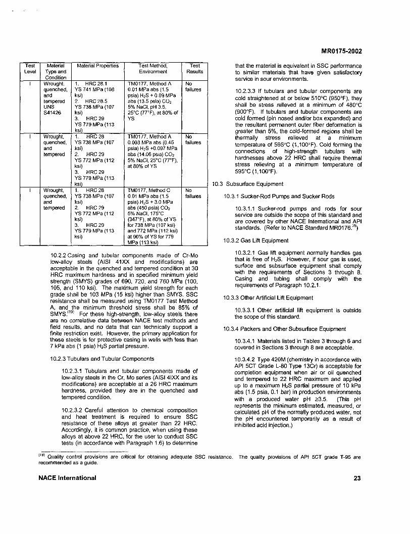
MR0175-2002
Test Level
Material Type and Condition
Material Properties Test Method, Environment
Test Results
I Wrought, quenched, and tempered UNS S41426
1. HRC 28.1 YS741 MPa (108 ksi) 2. HRC 28.5 YS 738 MPa (107 ksi) 3. HRC 29 YS 779 MPa (113 ksi)
TM0177, Method A 0.01 MPa abs (1.5 psia) H 2S + 0.09 MPa abs (13.5 psia) C 0 2
5% NaCI, pH 3.5, 25°C (77° F), at 80% of YS
No failures
I Wrought, quenched, and tempered
1. HRC 28 YS738 MPa (107 ksi) 2. HRC 29 YS 772 MPa (112 ksi) 3. HRC 29 YS 779 MPa (113 ksi)
TM0177, Method A 0.003 MPa abs (0.45 psia) H 2S +0.097 MPa abs (14.06 psia) C 0 2
5% NaCI, 25°C (77°F), at 80% of YS
No failures
I Wrought, quenched, and tempered
1. HRC 28 YS 738 MPa (107 ksi) 2. HRC 29 YS772 MPa (112 ksi) 3. HRC 29 YS779 MPa (113 ksi)
TM0177, Method C 0.01 MPa abs (1.5 psia) H 2S + 3.0 MPa abs (450 psia) C 0 2
5% NaCI, 175°C (347°F), at 80% ofYS for 738 MPa (107 ksi) and 772 MPa (112 ksi) at 90% of YS for 779 MPa (113 ksi)
No failures
10.2.2 Casing and tubular components made of Cr-Mo low-alloy steels (AISI 41XX and modifications) are acceptable in the quenched and tempered condition at 30 HRC maximum hardness and in specified minimum yield strength (SMYS) grades of 690, 720, and 760 MPa (100, 105, and 110 ksi). The maximum yield strength for each grade shall be 103 MPa (15 ksi) higher than SMYS. SSC resistance shall be measured using TM0177 Test Method A, and the minimum threshold stress shall be 85% of SMYS.'19' For these high-strength, low-alloy steels there are no correlative data between NACE test methods and field results, and no data that can technically support a finite restriction exist. However, the primary application for these steels is for protective casing in wells with less than 7 kPa abs (1 psia) H2S partial pressure.
10.2.3 Tubulars and Tubular Components
10.2.3.1 Tubulars and tubular components made of low-alloy steels in the Cr, Mo series (AISI 4IXX and its modifications) are acceptable at a 26 HRC maximum hardness, provided they are in the quenched and tempered condition.
10.2.3.2 Careful attention to chemical composition and heat treatment is required to ensure SSC resistance of these alloys at greater than 22 HRC. Accordingly, it is common practice, when using these alloys at above 22 HRC, for the user to conduct SSC tests (in accordance with Paragraph 1.6) to determine
that the material is equivalent in SSC performance to similar materials that have given satisfactory service in sour environments.
10.2.3.3 If tubulars and tubular components are cold straightened at or below 510°C (950°F), they shall be stress relieved at a minimum of 480°C (900°F). If tubulars and tubular components are cold formed (pin nosed and/or box expanded) and the resultant permanent outer fiber deformation is greater than 5%, the cold-formed regions shall be thermally stress relieved at a minimum temperature of 595°C (1,100°F). Cold forming the connections of high-strength tubulars with hardnesses above 22 HRC shall require thermal stress relieving at a minimum temperature of 595°C(1,100°F).
10.3 Subsurface Equipment
10.3.1 Sucker-Rod Pumps and Sucker Rods
10.3.1.1 Sucker-rod pumps and rods for sour service are outside the scope of this standard and are covered by other NACE International and API standards. (Refer to NACE Standard MR0176.29)
10.3.2 Gas Lift Equipment
10.3.2.1 Gas lift equipment normally handles gas that is free of H2S. However, if sour gas is used, surface and subsurface equipment shall comply with the requirements of Sections 3 through 8. Casing and tubing shall comply with the requirements of Paragraph 10.2.1.
10.3.3 Other Artificial Lift Equipment
10.3.3.1 Other artificial lift equipment is outside the scope of this standard.
10.3.4 Packers and Other Subsurface Equipment
10.3.4.1 Materials listed in Tables 3 through 6 and covered in Sections 3 through 8 are acceptable.
10.3.4.2 Type 420M (chemistry in accordance with API 5CT Grade L-80 Type 13Cr) is acceptable for completion equipment when air or oil quenched and tempered to 22 HRC maximum and applied up to a maximum H2S partial pressure of 10 kPa abs (1.5 psia, 0.1 bar) in production environments with a produced water pH >3.5. (This pH represents the minimum estimated, measured, or calculated pH of the normally produced water, not the pH encountered temporarily as a result of inhibited acid injection.)
< 1 9 ) Quality control provisions are critical for obtaining adequate SSC resistance, recommended as a guide.
The quality provisions of API 5CT grade T-95 are
NACE International 23

MR0175-2002
10.3.5 Slips
10.3.5.1 Slips are outside the scope of this standard.
10.4 Wellheads
10.4.1 Wellhead components directly exposed to sour environments shall be manufactured in accordance with the requirements of Sections 3 through 8. Wellhead components that are not directly exposed to the sour environment or that are exposed to the controlled drilling environment (see Paragraph 11.2.2) are outside the scope of this standard.
10.5 Flow Lines and Gathering Lines
10.5.1 Materials and fabrication procedures shall comply with the requirements of Sections 3 through 8 and Tables 3 through 5.
10.6 Production Facilities
10.6.1 Oil and Gas Processing and Injection Facilities
10.6.1.1 Materials and fabrication procedures shall comply with the requirements of Sections 3 through 8 and Tables 3 through 5.
10.6.2 Cryogenic Gas Processing Plants
10.6.2.1 The use of alloy steels containing more than approximately 1% nickel may be desirable in low-temperature service to provide resistance to brittle fracture. Because of the absence of water in this service, these alloys are acceptable, provided that adequate precautions (such as protecting the equipment by using inhibited methanol) are taken during startup and shutdown. Typical steels included in the class are ASTM A 33330 Grades 3, 4, 7, 8, and 9; A 33431; A 20332; A 4203 3 Grades WPL-3 WPL-6, and WPL-8; A 35034 Grade LF 3; A 3533S; and A 689.36
10.6.3 Water Injection and Water Disposal
10.6.3.1 Materials selection for water-handling facilities is outside the scope of this standard. Refer to NACE Standard RP0475.
10.7 Compressors and Pumps
10.7.1 Materials exposed to the sour environment shall comply with the requirements of Sections 3 through 8, except as noted in Paragraphs 10.7.2 and 10.7.3.
10.7.2 Gray cast iron (ASTM A 278°' Class 35 or 40) and nodular iron (ASTM A 395) are acceptable as compressor cylinders, liners, pistons, and valves. Aluminum alloy 355, temper T-7 (ASTM B 26s 8), is acceptable for pistons. Aluminum, soft carbon steel, and soft, low-carbon iron are acceptable as gaskets in compressors handling sour gas.
10.7.3 AISI 4320 and a modified version of 4320 that contains 0.28 to 0.33% carbon are acceptable for compressor impellers at a maximum yield strength of 620 MPa (90 ksi) provided they have been heat treated in accordance with Paragraph 10.7.3.1.
10.7.3.1 Heat-Treat Procedure (Three-Step Process)
(1) Austenitize and quench.
(2) Temper at 620°C (1,150°F) minimum, but below the lower critical temperature. Cool to ambient temperature before the second temper.
(3) Temper at 620°C (1,150°F) minimum, but lower than the first tempering temperature. Cool to ambient temperature.
10.8 Pipe Fittings
10.8.1 Carbon steels meeting the requirements of ASTM A 105 or A 23439 Grades WPB and WPC are acceptable in the hot-worked condition to the following maximum hardnesses: A 105 (187 HB); and A 234 WPB and WPC (197 HB).
10.8.2 If carbon steel ASTM A 234 Grades WPB and WPC pipe fittings are cold worked during manufacture by rolling, forging, or any other manufacturing process which results in a permanent outer fiber deformation greater than 5%, the cold working must be followed by normalizing or thermal stress-relief heat treatment. If thermal stress relief is applied, it should be performed in accordance with ASME Code, Section VIII, Division 1, except that the minimum stress-relief temperature shall be 595°C (1,100°F). After thermal heat treatment subsequent to cold work, the hardness of normalized or stress-relieved ASTM A 234 Grade WPB or WPC carbon steel pipe fittings shall not exceed 200 HB.
Section 11: Drilling and Well-Servicing Equipment
11.1 General. Metallic materials used for drilling and well- fabricated in compliance with Section 5, except as servicing equipment shall meet the requirements of this section otherwise indicated herein, if they are to be exposed to sour environments and shall be
11.2 Control of Drilling and Well-Servicing Environments
24 NACE International
MR0175-2002
11.2.1 The service stresses involved in drilling and well-servicing operations often require the use of materials and components having hardness (strength) greater than that permitted for carbon and low-alloy steels in Section 3. When such materials and components are required for drilling formations or are operating in environments containing H2S, the primary means for avoiding SSC is control of the drilling or well-servicing environment. As service stresses and material hardnesses increase, drilling fluid control becomes increasingly important.
11.2.2 The drilling environment is controlled by maintenance of drilling fluid hydrostatic head and fluid density to minimize formation fluid in-flow and by the use of one or more of the following: (1) maintenance of pH 10 or higher to neutralize H2S in the drilled formation; (2) use of chemical sulfide scavengers; and (3) use of a drilling fluid in which oil is the continuous phase.
11.2.3 When aluminum drill pipe is used, the drilling fluid pH should not exceed 10.5 to avoid accelerated weight-loss corrosion.
11.3 Drilling Equipment
11.3.1 Drill Stem
11.3.1.1 Drill pipe, tool joints, drill collars, and other tubular components.
11.3.1.1.1 Tubular steel components meeting API specifications listed in Table 5 are acceptable if the drilling environment is controlled (see Paragraph 11.2). For optimum SSC resistance, steel components having specified minimum yield strengths greater than 660 MPa (95 ksi) should be heat treated by quenching and tempering.
11.3.1.2 Welding of Tool Joints to Drill Pipe
11.3.1.2.1 The weld and heat-affected zone (HAZ) shall be heat treated by austenitizing, cooling to a temperature below the transformation range, and tempering at a minimum tempering temperature of 595°C (1,100°F).
11.3.1.3 Hardsurfacing
11.3.1.3.1 Hardsurfacing deposits on tubular drilling components may be applied only to regions of increased cross-section where service stresses are reduced. These deposits do not require heat treatment after being applied.
11.3.2 Drill Bits
11.3.2.1 Drill bits are outside the scope of this standard.
11.3.3 Other Drilling Components
11.3.3.1 Other drilling components (slush pumps, swivels, kelly cocks, etc.) shall be manufactured from
materials in compliance with Sections 3 through 8. Parts of these components that are isolated from the sour drilling fluid or that are exposed only to the controlled drilling fluid environment (see Paragraph 11.2.2) are outside the scope of this standard.
11.4 Blowout Preventer (BOP)
11.4.1 Blowout preventer body and parts (excluding ram and ram shear blades) shall meet the requirements of Sections 3 through 8.
11.4.2 Blowout Preventer Shear Blades
11.4.2.1 High-strength and high-hardness steels are required for ram shear blades to shear drill pipe during drilling emergency conditions. However, the user shall be advised that these materials are highly susceptible to SSC.
11.4.3 Rams
11.4.3.1 Low-alloy steels, processed in accordance with Sections 3 through 8, are acceptable for rams. Low-alloy steels in the chromium-molybdenum class (and its modifications) are acceptable as rams at 26 HRC maximum in the quenched and tempered condition. Careful attention to chemical composition and heat treatment is required to ensure SSC resistance of these alloys at hardness levels greater than 22 HRC. SSC tests shall be conducted to establish that the material is equivalent in SSC performance to materials that have given satisfactory service in sour environments.
11.5 Choke Manifolds and Choke and Kill Lines
11.5.1 Choke manifolds and choke and kill lines shall comply with the requirements of Sections 3 through 8.
11.6 Drill Stem Testing
11.6.1 Drill stem testing is not ordinarily conducted in a controlled drilling environment. Materials for drill stem testing shall comply with the requirements of Sections 3 through 8 and Paragraph 10.2 when testing without a controlled drilling environment.
11.6.2 Materials shown in Table 5 can also be used with operational procedures that take into consideration the factors enumerated in Paragraph 1.3, which may involve use of inhibitors, limited entry, limited time, limited pressure, and metallurgical or design factors. Such operational procedures are outside the scope of this standard (see API RP 7G 4 0) .
11.7 Formation-Testing Tools
11.7.1 Materials for formation-testing tools shall comply with the requirements of Sections 3 through 8 and Paragraph 10.2.
N A C E International 25
MR0175-2002
11.8 Floating Drilling Operations
11.8.1 Blowout Preventers (BOP)
11.8.1.1 Blowout preventers shall comply with the requirements of Paragraph 11.4.
11.8.2 Drilling Riser Systems
11.8.2.1 If the flow of sour formation fluids is handled by diverting the flow at the sea floor BOP through the choke and kill lines, the drilling riser pipe, riser connections, ball or flex joints, and telescoping joints need not comply with this standard. If, however, the riser system is to be exposed to sour environments, materials used shall meet the requirements of Sections 3 through 8 and Paragraph 10.2.1.1.
11.8.3 Choke and Kill Lines
11.8.3.1 Materials for the choke and kill lines and manifolds shall comply with the requirements of Sections 3 through 8.
11.9 Well-Servicing Equipment
11.9.1 Work String
11.9.1.1 Work strings used during well servicing when sour fluids are to be encountered shall comply with the requirements of Paragraph 11.8.1.1. Work strings that are to be exposed to controlled drilling fluid environments only are outside the scope of this standard.
11.9.2 Blowout Preventers
11.9.2.1 Blowout preventers shall comply with the requirements of Paragraph 11.4.
11.9.3 Choke and Kill Lines
11.9.3.1 Choke and kill lines and manifolds shall comply with the requirements of Sections 3 through 8.
11.9.4 Production Test Facilities
11.9.4.1 Production test facilities shall comply with the requirements of Sections 3 through 8.
11.9.5 Wire Line Lubricator Assembly
11.9.5.1 Wire line lubricator and auxiliary equipment shall comply with the requirements of Sections 3 through 8 and Paragraph 10.2.1.1.
References
1. E.M. Moore, J.J. Warga, "Factors Influencing the Hydrogen Cracking Sensitivity of Pipeline Steels," CORROSION/76, paper no. 144 (Houston, TX: NACE Inter-national, 1976).
2. NACE Standard TM0284 (latest revision), "Evaluation of Pipeline and Pressure Vessel Steels for Resistance to Hydrogen-Induced Cracking" (Houston, TX: NACE).
3. NACE Standard RP0475 (latest revision), "Selection of Metallic Materials to Be Used in All Phases of Water Handling for Injection into Oil-Bearing Formations" (Houston, TX: NACE).
4. NACE Standard TM0177 (latest revision), "Laboratory Testing of Metals for Resistance to Sulfide Stress Cracking and Stress Corrosion Cracking in H2S Environments" (Houston, TX: NACE).
5. Technical Committee Publications Manual (latest revision) (Houston, TX: NACE).
6. ASTM E 140 (latest revision), "Standard Hardness Conversion Tables for Metals — Relationship Among Brinell Hardness, Vickers Hardness, Rockwell Hardness, Rockwell Superficial Hardness, Knoop Hardness, and Scleroscope Hardness)" (West Conshohocken, PA: ASTM).
7. ASTM E 10 (latest revision), "Standard Test Method for Brinell Hardness of Metallic Materials" (West Conshohocken, PA: ASTM).
8. ASTM E 18 (latest revision), "Standard Test Methods for Rockwell Hardness and Rockwell Superficial Hardness of Metallic Materials" (West Conshohocken, PA: ASTM).
9. ASTM A 370 (latest revision), "Standard Test Methods and Definitions for Mechanical Testing of Steel Products" (West Conshohocken, PA: ASTM).
10. ASTM A 105/A 105M (latest revision), "Standard Specification for Carbon Steel Forgings for Piping Applications" (West Conshohocken, PA: ASTM).
11. ASME Boiler and Pressure Vessel Code, Section VIII, Division 1 (latest revision), "Rules for Construction of Pressure Vessels" (New York, NY: ASME).
12. ASTM A 53/A 53M (latest revision), "Standard Specification for Pipe, Steel, Black and Hot-Dipped, Zinc-Coated, Welded and Seamless" (West Conshohocken, PA: ASTM).
13. ASTM A 106 (latest revision), "Standard Specification for Seamless Carbon Steel Pipe for High-Temperature Service" (West Conshohocken, PA: ASTM). 14. API Spec 5L (latest revision), "Line Pipe" (Washington, DC: API).
15. ASTM A 395/A 395M (latest revision), "Standard Specification for Ferritic Ductile Iron Pressure-Retaining
26 NACE International
MR0175-2002
Castings for Use at Elevated Temperatures" (West Conshohocken, PA: ASTM).
16. ASTM A 351/A 351M (latest revision), "Standard Specification for Castings, Austenitic, Austenitic-Ferritic (Duplex), for Pressure-Containing Parts" (West Conshohocken, PA: ASTM).
17. ASTM A 743/A 743M (latest revision), "Standard Specification for Castings, Iron-Chromium, Iron-Chromium-Nickel, Corrosion Resistant, for General Application" (West Conshohocken, PA: ASTM).
18. ASTM A 744/A 744M (latest revision), "Standard Specification for Castings, Iron-Chromium-Nickel, Corrosion Resistant, for Severe Service" (West Conshohocken, PA: ASTM).
19. ASTM A 487 (latest revision), "Standard Specification for Steel Castings Suitable for Pressure Service" (West Conshohocken, PA: ASTM).
20. Z 6 CNDU 28.08 M (NF A 320-55 French National Standard).
21. ASTM A 494 (latest revision), "Standard Specification for Castings, Nickel and Nickel Alloy" (West Conshohocken, PA: ASTM).
22. AMS 4779 (latest revision), "Nickel Alloy, Brazing Filler Metal 94Ni - 3.5Si - 1.8B 1800 to 1950°F (982 to 1066°C) Solidus-Liquidus Range (UNS N99640)" (Warrendale, PA: SAE).
23. Military Specification MIL-S-13165 (latest revision), "Shot Peening of Metal Parts" (Philadelphia PA: Department of Defense Single Stock Point [DODSSP] ( 2 0 )).
24. API Spec 6A (latest revision), "Wellhead and Christmas Tree Equipment" (Washington, DC: API).
25. ASTM A 193/A 193M (latest revision), "Standard Specification for Alloy-Steel and Stainless Steel Bolting Materials for High-Temperature Service" (West Conshohocken, PA: ASTM).
26. ASTM A 194/A 194M (latest revision), "Standard Specification for Carbon and Alloy Steel Nuts for Bolts for High-Pressure and High-Temperature Service, or Both" (West Conshohocken, PA: ASTM).
27. ASTM A 747/A 747M (latest revision), "Standard Specification for Steel Castings, Stainless, Precipitation Hardening" (West Conshohocken, PA: ASTM).
28. API Spec 5CT (latest revision), "Casing and Tubing (U.S. Customary Units)" and API Spec 5CTM (latest revision), "Casing and Tubing (Metric Units)" (Washington, DC: API).
29. NACE Standard MR0176 (latest revision), "Metallic Materials for Sucker-Rod Pumps for Corrosive Oilfield Environments" (Houston, TX: NACE).
30. ASTM A 333/A 333M (latest revision), "Standard Specification for Seamless and Welded Steel Pipe for Low-Temperature Service" (West Conshohocken, PA: ASTM).
31. ASTM A 334/A 334M (latest revision), "Standard Specification for Seamless and Welded Carbon and Alloy-Steel Tubes for Low-Temperature Service" (West Conshohocken, PA: ASTM).
32. ASTM A 203/A 203M (latest revision), "Standard Specification for Pressure Vessel Plates, Alloy Steel, Nickel" (West Conshohocken, PA: ASTM).
33. ASTM A 420/A 420M (latest revision), "Standard Specification for Piping Fittings of Wrought Carbon Steel and Alloy Steel for Low-Temperature Service" (West Conshohocken, PA: ASTM).
34. ASTM A 350/A 350M (latest revision), "Standard Specification for Carbon and Low-Alloy Steel Forgings, Requiring Notch Toughness Testing for Piping Components" (West Conshohocken, PA: ASTM).
35. ASTM A 353/A 353M (latest revision), "Standard Specification for Pressure Vessel Plates, Alloy Steel, 9 Percent Nickel, Double-Normalized and Tempered" (West Conshohocken, PA: ASTM)
36. ASTM A 689 (latest revision), "Standard Specification for Carbon and Alloy Steel Bars for Springs" (West Conshohocken, PA: ASTM).
37. ASTM A 278/A 278M (latest revision), "Standard Specification for Gray Iron Castings for Pressure-Containing Parts for Temperatures up to 650°F" (West Conshohocken, PA: ASTM).
38. ASTM B 26/B 26M (latest revision), "Standard Specification for Aluminum-Alloy Sand Castings" (West Conshohocken, PA: ASTM).
39. ASTM A 234/A 234M (latest revision), "Standard Specification for Piping Fittings of Wrought Carbon Steel and Alloy Steel for Moderate and High Temperature Service" (West Conshohocken, PA: ASTM).
40. API RP 7G (latest revision), "Drill Stem Design and Operating Limits" (Washington, DC: API).
(20'Department of Defense Single Stock Point (DODSSP), Subscription Services Desk, 700 Robbins Ave., Bldg. 4D, Philadelphia, PA 19111-5094.
N A C E International 27
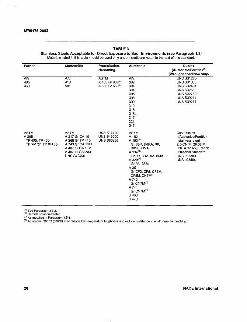
MR0175-2002
TABLE 3 Stainless Steels Acceptable for Direct Exposure to Sour Environments (see Paragraph 1.3)
Materials listed in this table should be used only under conditions noted in the text of this standard.
Ferritic Martensitic Precipitation-Hardening
Austenitic Duplex (Austenitic/Ferritic) (D)
(Wrought condition only) AISI AISI ASTM AISI UNS S31260 405 410 A 453 Gr660 < A ) 302 UNS S31803 430 501 A 638 Gr660 ( A ) 304 UNS S32404
304L UNS S32550 305 UNS S32760 308 UNS S39274 309 UNS S39277 310 316 316L 317 321 347
ASTM ASTM UNS S17400 ASTM Cast Duplex A 268 A 217 Gr CA 15 UNS S45000 A 182 (Austenitic/Ferritic)
TP 405, TP 430, A 268 GrTP410 UNS S66286 A 193 i B ) stainless steel TP XM 27, TP XM 33 A 743 Gr CA 15M Gr B8R, B8RA, B8, Z 6 CNDU 28.08 M,
A 487 CICA15M B8M,B8MA NF A 320-55 French A 487 CICA6NM A 194 ( B ) National Standard UNS S42400 Gr 8R, 8RA, 8A, 8MA UNS J93380
A 320 ( 8 ) UNS J93404 Gr B8, B8M
A 351 Gr CF3, CF8, CF3M, CF8M, CN7M(C>
A 743 Gr CN7M ( D )
A 744 Gr CN7M ( D |
B463 B473
See Paragraph 3.8.2. Carbide solution-treated. As modified in Paragraph 3.5.4. Aging over 260°C (500°F) may reduce low-temperature toughness and reduce resistance to environmental cracking.
28 NACE International

o CN
i n
©
ct
a.
O) co
rn
o or
CO Q .
a> 4) U)
c o E c
s > £ LU k-3 O CO o
UJ 3 (A
m a < X I— LU
*-« u 0 w cn I - -1
0>
ia ra a <u o * tn .5 *c a> n 2 to 3 O
o cu Q . cn CD
X3
o x: CO s=
j D c
cn .9 £ b
CO
•- -§ "S. !8
» 8. co o CD C L
"co To ^ .a
C o
CD S
C *
ro a)
is g co ro x "2 £ o o o x co 3 .£ CD > , x : =
"g 8 P o o OJ c c CO "5
§ = XJ ro
81 cz "a =J a> >, o c c
O CO
" ° o CD - £ '" ro
o CD it=
TJ c
re _ V)
re
O S 5 5
w Q . 0) co-CO o c re o O
(A >< O
3
E S .c o "o u Z
o m r--
o o CO <o o z CO
o
111 a> 5 c O i T3 Z O -P
7 co z CO 3 o
>> o 5
CO t a
3 o Z
(A
. O
Z E CD 3
•SE 5 p
o 00 00 o co
o
0) a. a. o o • o
o o
3 o z CO z 3
£ o
OT OT
I cn >< o
< o
<o ro CO >* o < oo m co
i T
0 tri
1 <
N-co !~r > ^ ° co < 2 <D< P C ro ro O <o
ai ^ y & < E
c?m 2 3 . ± CD H Z O
OT CN CM oo h~ CO a> o oo a> -3- 00 cn CD CO CD r>. N. (35 a> i n LO ID CD CD CD CD co CD CD cn i n m i n IT) UO i n CO i n cn
2 r-
< cn
w
OT
o o i n CN •*r co CD co i n i n CD CN i n i n i n N-
CO CD c- CO CD N-co CD to CD T— T— CD
-<— ̂— T— CO i n m CQ CQ CQ CO CO. m m
^ c o c o c o ^ i - i n t i n p I C D C D C N C N C N O O ^ T - C O T t ^ J - r J - N - N -< m c o c Q c o c o c D c a
5 CD T - CM O ) CM I D t CD CO CO T - CM CM
co in m co CD CD < m OQ ca co co CQ
o io co CM eo co t io io oo in ̂ t» CN CM CN co en o r» o CO t o I D CS S h> OD o o o o o © o Z Z Z Z Z Z Z c o c o c o c o c o c o c o c o c o z z z z z z z 3 3 3 3 3 3 3
00 CM CM o o co co o o
3 3
m io s in co CO CM N CM CO U) CO N CD o CO 00 CD CT> o o o o
z z z z CO CO CO CO CO z z z z z 3 3 3 3 3
2
co •<-CD r-h- co in in
^ c o c D S c o r o ^ - i n ' * £ c o c o o o o i - ' ^ c o ~ — co -s i -T j - 'S -mmin OT < C 0 C D C Q C Q C Q C Q C Q C D
OT 1 - j in o i - n S r— f~- co co co m in I D in N s CM ^ TJ- ^- ^ r-OT
OT
N . CO -<J- CD -<t CN CD CD CD CD r- T- co tn
< m co m CQ co
m m CO CO
S ^ 2 * CD O <
OT
OT
•cf ai 3
.C
C
8
•s |2
CN
Lit < W o
N -CM m UJ
CO
<
cn at
3 CD
2 < •a c CO tn CO a>
CO c 0
CO c
LU O <
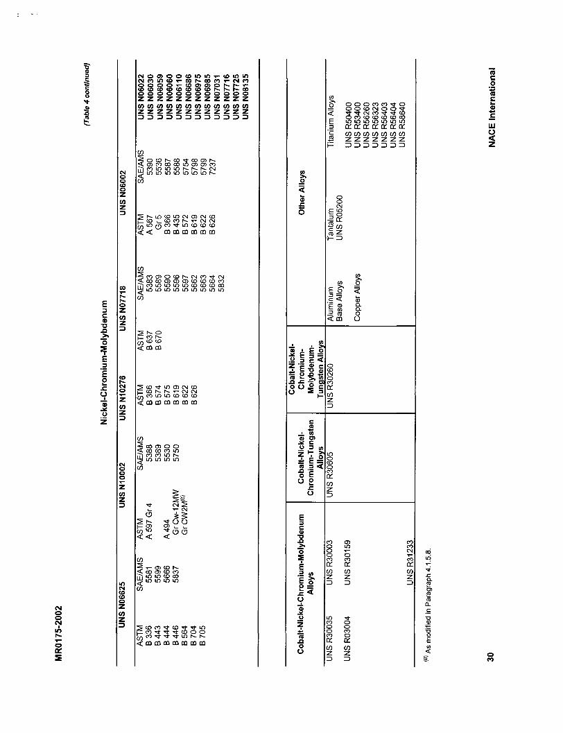
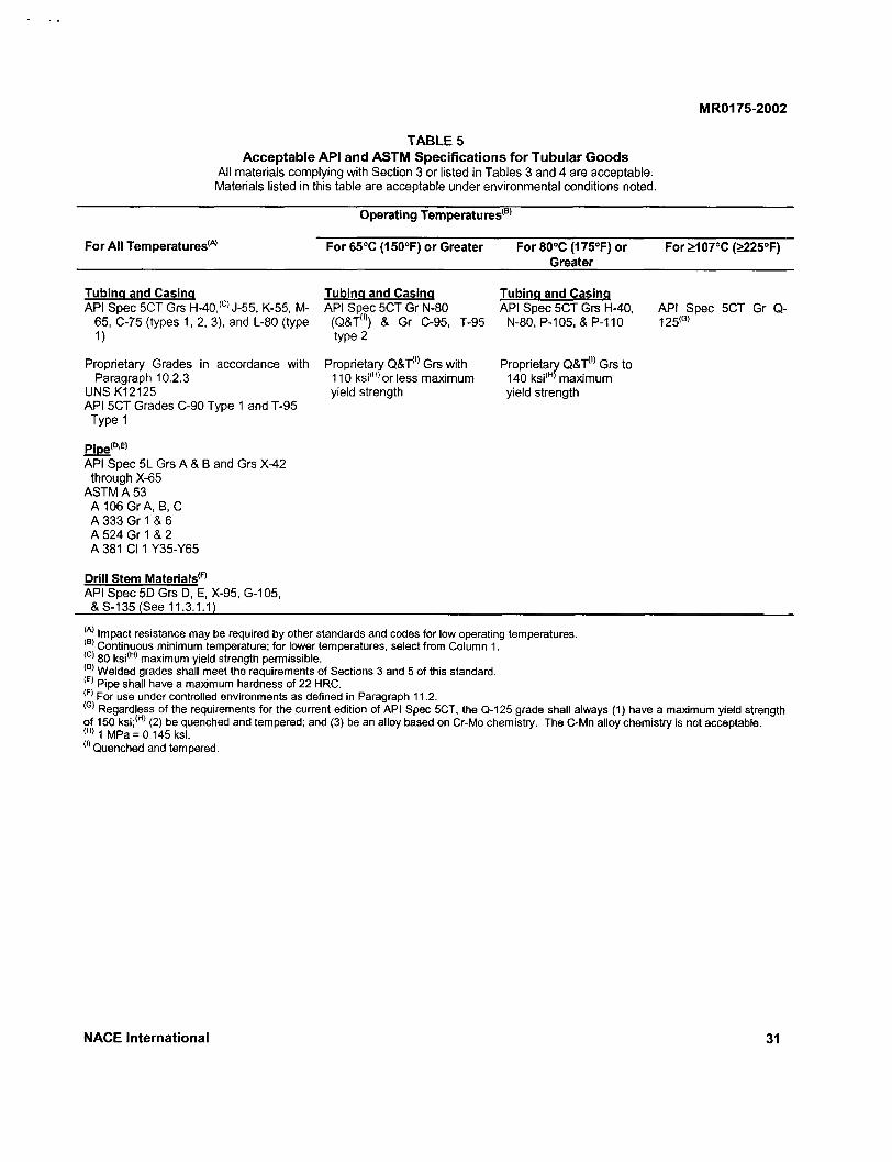
MR0175-2002
T A B L E 5 Acceptable API and ASTM Specifications for Tubular G o o d s
All materials complying with Section 3 or listed in Tables 3 and 4 are acceptable. Materials listed in this table are acceptable under environmental conditions noted.
Operating Temperatures'
ForAIITemperatures ( A ) For 65°C (150°F) or Greater For80°C(175°F)or For£l07°C (£225°F) Greater
Tubing and Casing API Spec 5CT Grs H-40,<c> J-55, K-55, M-
65, C-75 (types 1, 2, 3), and L-80 (type 1)
Proprietary Grades in accordance with Paragraph 10.2.3
UNS K12125 API 5CT Grades C-90 Type 1 and T-95
Type 1
Tubing and Casing API Spec 5CT Gr N-80
(Q&T ( I )) & Gr C-95, type 2
T-95
Proprietary Q&T 0 ' Grs with 110 ksi ( H )or less maximum yield strength
Tubing and Casing API Spec 5CT Grs H-40,
N-80, P-105, & P-110
Proprietary Q&T 0 1 Grs to 140 ksi< H > maximum yield strength
API Spec 5CT Gr Q-125(G»
Pipe'DE> API Spec 5L Grs A & B and Grs X-42
through X-65 ASTM A 53
A 106 GrA, B, C A 333 Gr 1 & 6 A 524 Gr 1 & 2 A 381 CI 1 Y35-Y65
Drill Stem Materials'1"1
API Spec 5D Grs D, E, X-95, G-105, &S-135 (See 11.3.1.1)
( A ) Impact resistance may be required by other standards and codes for low operating temperatures. < B ) Continuous minimum temperature; for lower temperatures, select from Column 1. < c ) 80 ksi'H > maximum yield strength permissible. | D ' Welded grades shall meet the requirements of Sections 3 and 5 of this standard. ( E | Pipe shall have a maximum hardness of 22 HRC. ( F ) For use under controlled environments as defined in Paragraph 11.2. < G ) Regardless of the requirements for the current edition of API Spec 5CT, the Q-125 grade shall always (1) have a maximum yield strength of 150 ksi; ( H ) (2) be quenched and tempered; and (3) be an alloy based on Cr-Mo chemistry. The C-Mn alloy chemistry is not acceptable. ( H ) 1 MPa = 0.145 ksi. ( I ) Quenched and tempered.
N A C E International 31

MR0175-2002
TABLE 6 Acceptable Materials for Subsurface Equipment
for Direct Exposure to Sour Environments (see Paragraph 1.3) All materials complying with Section 3 and listed in Tables 3 through 5 are acceptable.
Use Material
Drillable packer components Ductile iron (ASTM A 536, A 571) Drillable packer components Malleable iron (ASTM A 220, A 602) Compression members Gray iron (ASTM A 48, A 278) All 9Cr-1Mo(A)
ASTM A 199 GrT9 ASTM A 200 Gr T9 ASTM A 276, Type 9 ASTM A 182 Gr F9 ASTM 213 GrT9
'22 HRC maximum.
TABLE 7 Other Sources of Material Standards
1. Aerospace Material Specifications (AMS): Society of Automotive Engineers Inc. (SAE), 400 Commonwealth Drive, Warrendale, PA 15096.
2. American Iron and Steel Institute (AISI), 1133 15th St. NW, Washington, DC 20005-2701.
3. American National Standards Institute (ANSI), 11 West 42nd St., New York, NY 10036.
4. American Petroleum Institute (API), 1220 L St. NW, Washington, DC 20005.
5. ASME International, Three Park Ave., New York, NY 10016-5990.
6. American Society for Testing and Materials (ASTM), 100 Barr Harbor Dr., West Conshohocken, PA 19428-2959.
7. American Welding Society (AWS), P.O. Box 251040, Miami, FL 33126.
8. British Standards Institute (BSI), 2 Park St., London W1A 2BS, England.
9. Canadian Standards Association (CSA), 178 Rexdale Blvd., Toronto, Ontario, Canada M9W 1R3.
10. Deutsches Institut fur Normung (DIN), Postfach 1107, D-1000 Berlin 30, Federal Republic of Germany.
11. Metals and Alloys in the Unified Numbering System (UNS), a joint publication of ASTM International and the Society of Automotive Engineers Inc. (SAE), 400 Commonwealth Dr., Warrendale, PA 15096.
32 NACE International
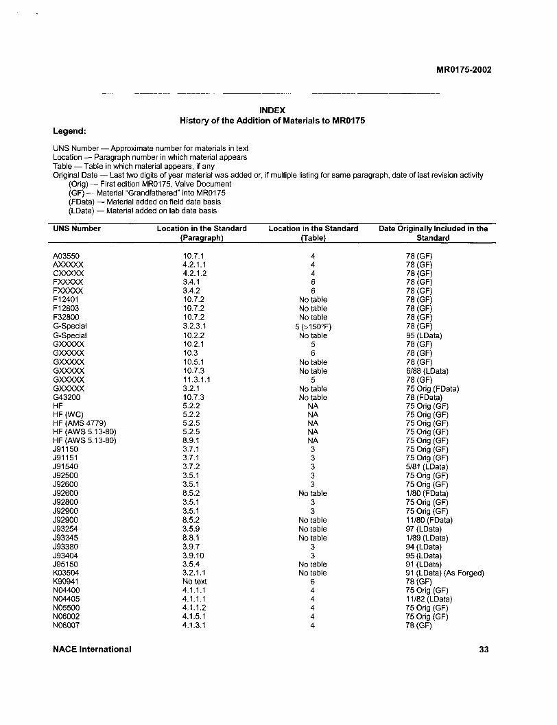
MR0175-2002
INDEX History of the Addition of Materials to MR0175
Legend:
UNS Number — Approximate number for materials in text Location — Paragraph number in which material appears Table — Table in which material appears, if any Original Date — Last two digits of year material was added or, if multiple listing for same paragraph, date of last revision activity
(Orig) — First edition MR0175, Valve Document (GF) — Material "Grandfathered" into MR0175 (FData) — Material added on field data basis (LData) — Material added on lab data basis
UNS Number Location in the Standard Location in the Standard Date Originally Included in the (Paragraph) (Table) Standard
A03550 10.7.1 4 78 (GF) AXXXXX 4.2.1.1 4 78 (GF) CXXXXX 4.2.1.2 4 78 (GF) FXXXXX 3.4.1 6 78 (GF) FXXXXX 3.4.2 6 78 (GF) F12401 10.7.2 No table 78 (GF) F12803 10.7.2 No table 78 (GF) F32800 10.7.2 No table 78 (GF) G-Special 3.2.3.1 5(>150°F) 78 (GF) G-Special 10.2.2 No table 95 (LData) GXXXXX 10.2.1 5 78 (GF) GXXXXX 10.3 6 78 (GF) GXXXXX 10.5.1 No table 78 (GF) GXXXXX 10.7.3 No table 6/88 (LData) GXXXXX 11.3.1.1 5 78 (GF) GXXXXX 3.2.1 No table 75 Orig (FData) G43200 10.7.3 No table 78 (FData) HF 5.2.2 NA 75 Orig (GF) HF (WC) 5.2.2 NA 75 Orig (GF) HF (AMS 4779) 5.2.5 NA 75 Orig (GF) HF (AWS 5.13-80) 5.2.5 NA 75 Orig (GF) HF(AWS 5.13-80) 8.9.1 NA 75 Orig (GF) J91150 3.7.1 3 75 Orig (GF) J91151 3.7.1 3 75 Orig (GF) J91540 3.7.2 3 5/81 (LData) J92500 3.5.1 3 75 Orig (GF) J92600 3.5.1 3 75 Orig (GF) J92600 8.5.2 No table 1/80 (FData) J92800 3.5.1 3 75 Orig (GF) J92900 3.5.1 3 75 Orig (GF) J92900 8.5.2 No table 11/80 (FData) J93254 3.5.9 No table 97 (LData) J93345 8.8.1 No table 1/89 (LData) J93380 3.9.7 3 94 (LData) J93404 3.9.10 3 95 (LData) J95150 3.5.4 No table 91 (LData) K03504 3.2.1.1 No table 91 (LData) (As Forged) K90941 No text 6 78 (GF) N04400 4.1.1.1 4 75 Orig (GF) N04405 4.1.1.1 4 11/82 (LData) N05500 4.1.1.2 4 75 Orig (GF) N06002 4.1.5.1 4 75 Orig (GF) N06007 4.1.3.1 4 78 (GF)
NACE International 33
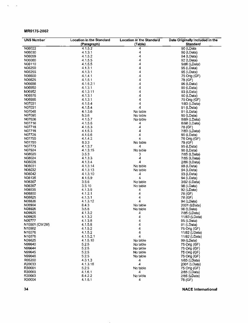
MR0175-2002
UNS Number Location in the Standard (Paragraph)
Location in the Standard (Table)
Date Originally Indue Standard
N06022 4.1.5.2 4 90 (LData N06030 4.1.3.1 4 90 (LData) N06059 4.1.5.2 4 94 (LData) N06060 4.1.5.5 4 92 (LData) N06110 4.1.5.5 4 9/86 (LData) N06250 4.1.3.1 4 95 (LData) N06255 4.1.3.1 4 95 (LData) N06600 4.1.4.1 4 75 Orig (GF) N06625 4.1.5.1 4 78 (GF) N06686 4.1.5.2.1 4 96 (LData) N06950 4.1.3.1 4 90 (LData) N06952 4.1.3.11 4 93 (LData) N06975 4.1.3.1 4 90 (LData) N06985 4.1.3.1 4 75 Orig (GF) N07031 4.1.5.4 4 1/83 (LData) N07031 4.1.5.4 4 91 (LData) N07048 4.1.3.6 No table 91 (LData) N07090 8.3.6 No table 90 (LData) N07626 4.1.5.7 No table 8/89 (LData) N07716 4.1.5.6 4 8/88 (LData) N07718 4.1.5.3 4 78 (GF) N07718 4.1.5.3 4 7/83 (LData) N07725 4.1.5.6 4 90 (LData) N07750 4.1.4.2 4 75 Orig (GF) N07750 8.3.3 No table 78 (GF) N07773 4.1.3.7 4 95 (LData) N07924 4.1.3.15 No table 98 (LData) N08020 3.5.3 3 7/85 (LData) N08024 4.1.3.3 4 7/85 (LData) N08028 4.1.3.4 4 2/86 (LData) N08031 4.1.3.14 No table 98 (LData) N08032 4.1.3.13 No table 94 (LData) N08042 4.1.3.10 4 93 (LData) N08135 4.1.5.9 4 94 (LData) N08367 3.5.6 No table 3/92 (LData) N08367 3.5.10 No table 98 (LData) N08535 4.1.3.9 4 92 (LData) N08800 4.1.2.1 4 78 (GF) N08825 4.1.3.1 4 78 (GF) N08826 4.1.3.12 4 94 (LData) N08904 8.4.3 No table 2001 (LData) N08926 3.5.8 No table 96 (LData) N09925 4.1.3.2 4 7/85 (LData) N09925 4.1.3.2 4 11/83 (LData) N09777 4.1.3.8 4 95 (LData) N10001 (CW2M) 4.1.5.8 4 91 (LData) N10002 4.1.5.2 4 75 Orig (GF) N10276 4.1.5.2 4 11/82 (LData) N10276 4.1.5.2.1 4 11/82 (LData) N26625 4.1.5.10 No table 99 (LData) N99640 5.2.5 No table 75 Orig (GF) N99644 5.2.5 Notable 75 Orig (GF) N99645 5.2.5 No table 75 Orig (GF) N99646 5.2.5 No table 75 Orig (GF) R05200 4.3.1.3 4 1/85 (LData) R20033 4.1.3.16 4 2001 (LData) R30001 5.2.5 No table 75 Orig (GF) R30003 4.1.6.1 4 2/85 (LData) R30003 8.4.2.2 No table 2/85 (LData) R30004 4.1.6.1 4 78 (GF)
34 NACE International
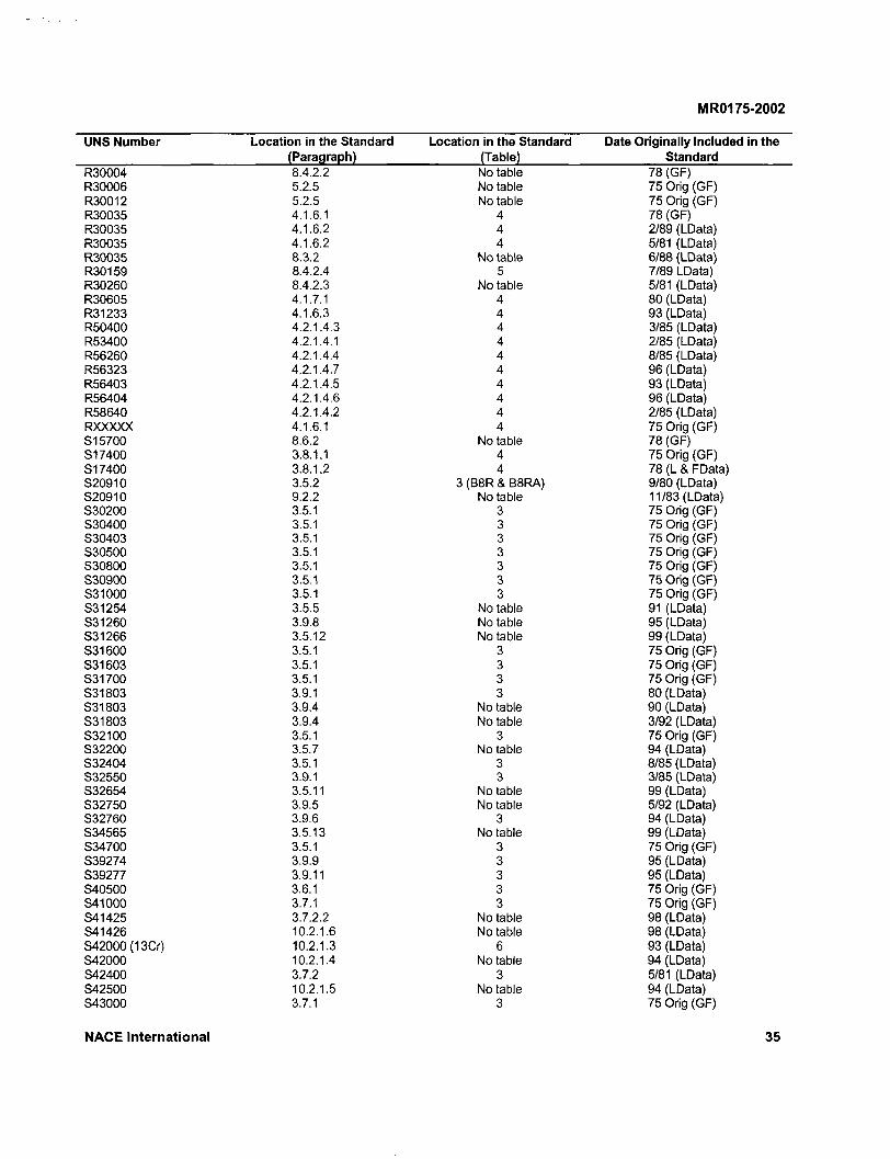
MR0175-2002
UNS Number Location in the Standard Location in the Standard Date Originally Included in the (Paragraph) (Table) Standard
R30004 8.4.2.2 No table 78 (GF) R30006 5.2.5 No table 75 Orig (GF) R30012 5.2.5 No table 75 Orig (GF) R30035 4.1.6.1 4 78 (GF) R30035 4.1.6.2 4 2/89 (LData) R30035 4.1.6.2 4 5/81 (LData) R30035 8.3.2 No table 6/88 (LData) R30159 8.4.2.4 5 7/89 LData) R30260 8.4.2.3 No table 5/81 (LData) R30605 4.1.7.1 4 80 (LData) R31233 4.1.6.3 4 93 (LData) R50400 4.2.1.4.3 4 3/85 (LData) R53400 4.2.1.4.1 4 2/85 (LData) R56260 4.2.1.4.4 4 8/85 (LData) R56323 4.2.1.4.7 4 96 (LData) R56403 4.2.1.4.5 4 93 (LData) R56404 4.2.1.4.6 4 96 (LData) R58640 4.2.1.4.2 4 2/85 (LData) RXXXXX 4.1.6.1 4 75 Orig (GF) S15700 8.6.2 No table 78 (GF) S17400 3.8.1.1 4 75 Orig (GF) S17400 3.8.1.2 4 78 (L & FData) S20910 3.5.2 3 (B8R & B8RA) 9/80 (LData) S20910 9.2.2 No table 11/83 (LData) S30200 3.5.1 3 75 Orig (GF) S30400 3.5.1 3 75 Orig (GF) S30403 3.5.1 3 75 Orig (GF) S30500 3.5.1 3 75 Orig (GF) S30800 3.5.1 3 75 Orig (GF) S30900 3.5.1 3 75 Orig (GF) S31000 3.5.1 3 75 Orig (GF) S31254 3.5.5 No table 91 (LData) S31260 3.9.8 No table 95 (LData) S31266 3.5.12 No table 99 (LData) S31600 3.5.1 3 75 Orig (GF) S31603 3.5.1 3 75 Orig (GF) S31700 3.5.1 3 75 Orig (GF) S31803 3.9.1 3 80 (LData) S31803 3.9.4 No table 90 (LData) S31803 3.9.4 No table 3/92 (LData) S32100 3.5.1 3 75 Orig (GF) S32200 3.5.7 No table 94 (LData) S32404 3.5.1 3 8/85 (LData) S32550 3.9.1 3 3/85 (LData) S32654 3.5.11 No table 99 (LData) S32750 3.9.5 No table 5/92 (LData) S32760 3.9.6 3 94 (LData) S34565 3.5.13 No table 99 (LData) S34700 3.5.1 3 75 Orig (GF) S39274 3.9.9 3 95 (LData) S39277 3.9.11 3 95 (LData) S40500 3.6.1 3 75 Orig (GF) S41000 3.7.1 3 75 Orig (GF) S41425 3.7.2.2 No table 98 (LData) S41426 10.2.1.6 No table 98 (LData) S42000(13Cr) 10.2.1.3 6 93 (LData) S42000 10.2.1.4 No table 94 (LData) S42400 3.7.2 3 5/81 (LData) S42500 10.2.1.5 No table 94 (LData) S43000 3.7.1 3 75 Orig (GF)
NACE International 35

MR0175-2002
UNS Number Location in the Standard Location in the Standard Date Originally Included in the (Paragraph) (Table) Standard
S44625 3.7.1 3 78 (GF) S44626 3.7.1 3 78 (GF) S45000 3.8.3 3 5/81 (LData) S50100 3.7.1 3 78 (GF) S66286 3.8.2 3 75 Orig (GF)
ASTM Number (chemical composition only)
CB7CU-1 (ASTM A 747) 9.3.1 No table 93 (LData) CN7M(ASTMA351, 3.5.4 No table 92 (LData) A 743, A 744)
CW2M (ASTM A 494) 4.1.5.8 No table 93 (LData) CK3MCuN (ASTM A 351, 3.5.9 No table 97 (LData) A 743, A 744) Others Z6CNDU 28.08 M (NF A 3.9.2 3 9/85 (LData) 320-55 French National Standard)
36 NACE International