Embed Size (px)
Citation preview

STANDARD FORM TECHNICAL SPECIFICATION FOR CONSTRUCTION OF
SEPTIC TANK EFFLUENT DRAINAGE SCHEMES
ii
CONTENTS PART B1 - MATERIALS AND EQUIPMENT 1 B1.1 GENERAL 2 B1.2 PIPES, FITTINGS AND JOINTING MATERIALS 2
B1.2.1 Rising Mains 2 B1.2.2 Rubber Rings 2 B1.2.3 Gravity Drains 2 B1.2.4 Cleaning Fluid and Solvent Cement 2 B1.2.5 Ductile Iron Cement Lined (DICL) Pipes and Fittings 2 B1.2.6 Nuts, Bolts, Washers & Gaskets for Pipe Flanges,
Checker Plate Covers, Frames and Fittings 4 B1.2.7 Galvanised Steel Tube and Fittings 4 B1.2.8 Polyethylene Pipe and Fittings 4 B1.2.9 Stainless Steel 4 B1.2.10 Pipe Brackets, Supports and Fixings etc 4 B1.2.11 Sealant for Openings in Concrete Structures 4 B1.2.12 Geotextile Fabric 4
B1.3 VALVES 5 B1.4 PIPE BEDDING 5
B1.4.1 Sand 5 B1.4.2 10mm Aggregate 5
B1.5 BACKFILLING 6 B1.5.1 Sand 6 B1.5.2 Ordinary Fill 6
B1.6 PAVEMENT MATERIALS 6 B1.6.1 Quarry Rubble 6 B1.6.2 Crushed Rock 6 B1.6.3 Bituminous Emulsion 6 B1.6.4 Aggregate 6 B1.6.5 Cold Mix 7 B1.6.6 Materials Sampling and Testing 7
B1.7 CONCRETE MATERIALS 7 B1.7.1 Cement 7 B1.7.2 Water 7 B1.7.3 Fine Aggregate 7 B1.7.4 Coarse Aggregate 7 B1.7.5 Cement Mortar 8 B1.7.6 Concrete 8 B1.7.8 Precast Concrete Components 8
B1.8 FERROUS COMPONENTS 9 B1.8.1 Flushing Point and Manhole Covers (Cast Iron) - General 9 B1.8.2 Materials 9 B1.8.3 Tolerances and Dimensions 9 B1.8.4 Identification Disk 9 B1.8.5 Chequer Plate Covers, Frames and Fittings 9
B1.9 FENCING 9 B1.9.1 Lagoon Diversion Fencing 9

iii
B1.9.2 Security Fencing for Lagoons and Treatment Plants 10 B1.9.3 Evaporation Pan Fencing 10
B1.10 PUMP SHEDS AND HOUSINGS 10
PART B2 - CONCRETE CONSTRUCTION STANDARDS 11 B2.1 SCOPE 12 B2.2 MIXING 12
B2.2.1 Site Mixed Supply - Concrete 12 B2.2.2 Ready-Mixed Supply - Concrete 12 B2.2.3 No-Fines Concrete - Concrete 13 B2.2.4 Inspection 13 B2.2.5 Rejection - Concrete 13 B2.2.6 Formwork 13 B2.2.7 Dimensional Tolerances - Concrete 14 B2.2.8 Formed Surfaces 14 B2.2.9 Lost Formwork - Concrete 14 B2.2.10 Form Coatings - Release Agents 14
B2.3 PLACING 14 B2.3.1 Weather Conditions 14 B2.3.2 Placing 14 B2.3.3 Compaction 14
B2.4 CURING 15 B2.5 PROTECTION 15
B2.5.1 The Contractor shall: 15 B2.5.2 Protection Lining of Concrete Pump Sumps 15
B2.6 PRECAST UNITS 15 B2.6.1 Standard 15 B2.6.2 Marking and Identification 15 B2.6.3 Handling Precast Units 16 B2.6.4 Installing Precast Units - Concrete 16 B2.6.5 Precast Dimensional Tolerance 16
PART B3 - EXCAVATION, BACKFILL AND REINSTATEMENT 17 B3.1 NOTICE BEFORE COMMENCEMENT OF WORKS 18 B3.2 SITE PREPARATION 18
B3.2.1 Site Preparation 18 B3.2.2 Topsoil 18
B3.3 EXCAVATION 18 B3.3.1 Generally 18 B3.3.2 Hand Digging of Trenches 19 B3.3.3 Mechanical Boring & PVC Sleeving 19 B3.3.4 Tolerances 19 B3.3.5 Over Excavation 19 B3.3.6. Excess Soil and Rock 20 B3.6.7 Excavation Under Obstructions 20 B3.3.8 Responsibility for Damage by Floodwaters etc 20 B3.3.9 Trenches Open Exceeding 48 Hours 21 B3.3.10 Excavation - Bituminised Roads 21
B3.4 DEWATERING - PROVISIONAL SUM 21 B3.4.1 Pipe bedding in Ground Water 22
B3.5 ROCK EXCAVATION � PROVISIONAL SUM 22
iv
B3.5.1 Use of explosives 23 B3.5.2 Definition of rock 23 B3.5.3 Measurement and payment of rock excavation 23
B3.6 SHORING 24 B3.6.1 General 24 B3.6.2 CLOSE SHORING - Provisional Sum 24
B3.7 BACKFILL 25 B3.7.1 Initial Backfill, Drains, Rising Mains 25 B3.7.2 Backfill Generally 25 B3.7.3 Backfill Class 'A' 25 B3.7.4 Backfill Class 'B' 26 B3.7.5 Backfill Class 'C' 26 B3.7.6 Backfill Class 'D' 26 B3.7.7 Definitions 26
B3.8 REINSTATEMENT OF PROPERTY, PAVEMENTS AND FOOTWAYS 27 B3.8.1 Making good 27 B3.8.2 Reinstatement of roads & footways 27 B3.8.3 Reinstatement of Footways 29 B3.8.4 Reinstatement Defective Footways 29 B3.8.5 TESTING TRENCH COMPACTION - Provisional Cost Item 29
PART B4 - GRAVITY DRAINS, RISING MAINS AND MANHOLES 30 B4.1 INSTALLATION OF DRAINS, RISING MAINS AND PROPERTY CONNECTIONS 31
B4.1.1 Storage and Handling of uPVC Pipes 31 B4.1.2 Cooling of uPVC Drains before Backfilling 31 B4.1.3 Excavation 31 B4.1.4 Pipe Bedding 31 B4.1.5 Trench Base Stabilisation 31 B4.1.6 Pipe Laying 32 B4.1.7 Solvent Welded Joints - uPVC 32 B4.1.8 Solvent Cement 33 B4.1.9 Expansion Joints and Fittings 33 B4.1.10 Rubber Ring Joints 33 B4.1.11 Backfill 33
B4.2 FLUSHING POINTS 33 B4.3 PROPERTY CONNECTIONS 34 B4.4 MANHOLES 34
B4.4.1 Excavation and preparation of subgrade 34 B4.4.2 Manhole Construction 34 B4.4.3 Sealing of Manholes 35 B4.4.4 Backfill around and testing of manholes 35
B4.5 TESTING OF GRAVITATIONAL DRAINS 35 B4.6 TESTING OF RISING MAINS 36 B4.7 DRAINS OR RISING MAINS UNDER CREEK BED 36 B4.8 THRUST BLOCKS ON RISING MAINS 37 B4.9 LOCATION MARKER POSTS FOR RISING MAINS 37 B4.10 VALVES ON RISING MAINS 37 B4.11 GALVANISED STEEL PIPE BELOW GROUND 37 B4.13 FLUSHING OF GRAVITATIONAL DRAINS 37 B4.14 FLUSHING OF RISING MAINS 37

v
PART B5 - PUMPING STATIONS 38 B5.1 EXCAVATION FOR AND CONSTRUCTION OF PUMP STATION/S 39
B5.1.1 Excavation and preparation of subgrade for pump sump 39 B5.1.2 Pump sump construction 39
B5.2 SEALING OF PUMP SUMPS 39 B5.2.1 Circumferential joints 39 B5.2.2 Openings through pump station walls 39
B5.3 TESTING OF PUMP SUMP/S 40 B5.4 BACKFILL AROUND PUMP SUMPS 40 B5.5 VALVE INSPECTION BOX 40 B5.6 PUMP HOUSING 40 B5.7 VENTING OF PUMPING SUMPS 41 B5.8 INSTALLATION AND OPERATION OF PUMPS AND EQUIPMENT 41 B5.9 PUMPS AND EQUIPMENT 41
B5.9.1 General 41 B5.9.2 Submersible sewage pumps and motors 41 B5.9.3 Positive Displacement Pumps 42 B5.9.4 Pump Bases and Beds (Above Ground Pumps) 44
B5.10 CONTROL SWITCHBOARD AND SWITCHGEAR 44 B5.10.1 General 44 B5.10.2 Control Equipment 44 B5.10.3 Level Control Switches 46 B5.10.4 Control and Alarm Systems 46 B5.10.5 Summary of Equipment Schedule 50
B5.11 PUMP OPERATION 51 B5.12 METER CABINET, SWITCHBOARD AND PUMP CONTROL BOARD 52
B5.12.1 General 52 B5.12.2 Construction 52 B5.12.3 Metering Section 52 B5.12.4 Pump Control Section 52 B5.12.5 Meter and Control Cabinet in Pump Shed 52
B5.13 SERVICE WIRING 53 B5.14 ELECTRICITY SUPPLY TO A SERVICE SUPPLY POINT 53 B5.15 ELECTRIC WIRING 53 B5.16 SWITCH BOARD CIRCUIT PROTECTION 53 B5.17 POWER OUTLETS 53 B5.18 TESTING 53 B5.19 INSTRUCTION OF THE PRINCIPLES REPRESENTATIVE 54 B5.20 CIRCUIT DIAGRAMS 54 B5.21 OPERATING MANUAL 54
PART B6 - OXIDATION AND EVAPORATION LAGOONS 55
PART C 58
1
PART B1 - MATERIALS AND EQUIPMENT
CONTENTS
CLAUSE Page
B1.1 GENERAL 2
B1.2 PIPES, FITTINGS AND JOINTING MATERIALS 2
B1.3 VALVES 4
B1.4 PIPE BEDDING 5
B1.5 BACKFILLING 6
B1.6 PAVEMENT MATERIALS 6
B1.7 CONCRETE MATERIALS 7
B1.8 FERROUS COMPONENTS 9
B1.9 FENCING 9
B1.10 PUMP SHEDS AND HOUSINGS 10

2
PART B1 - MATERIALS AND EQUIPMENT
B1.1 GENERAL
The Contractor shall supply all materials and equipment required for this Contract. Materials and equipment may include the following and shall conform with the Standards specified herein.
B1.2 PIPES, FITTINGS AND JOINTING MATERIALS
B1.2.1 Rising Mains
Pipes shall have ends formed for rubber ring joints and shall be
uPVC Classes .................................... as detailed on the design drawings conforming with
AS1477 Part 1 and 6. Fittings for class ........................................................... pipe shall be
uPVC Class ........................................................... conforming with AS1477 Parts 2 and 6.
B1.2.2 Rubber Rings
Rings shall be of Styrene-Butadiene or Natural Rubber with a Durometer hardness in the range 41-50 measured at 10 seconds delay at 20°C and shall conform with AS1646.
B1.2.3 Gravity Drains
Pipes and fittings shall be of UPVC (Unplasticised Polyvinyl Chloride) Class DWV, plain/solid wall complying with AS1260.
Pipe ends shall be formed for solvent welded joints.
B1.2.4 Cleaning Fluid and Solvent Cement
Solvent cement shall be coloured, suitable for use with Rigid uPVC Pipe and Fittings in accordance with the manufacturers directions. Solvent cement to be of the slow-setting type unless otherwise approved.
Cleaning fluid shall be compatible for use with and of distinctively different colour to the solvent cement in accordance with the manufacturers directions.
B1.2.5 Ductile Iron Cement Lined (DICL) Pipes and Fittings
Ductile iron cement lined pipes and fittings shall comply with the latest edition of AS2280 - "Centrifugally Cast Ductile Iron Pressure Pipes".
Pipe joints shall be either flanged or spigot and socket using the tyton joint.
Joint types shall be as shown on the drawings.
Tyton gaskets shall be manufactured from natural rubber and comply with the latest edition of AS1646 - "Rubber Joint Rings for Water Supply, Sewerage and Drainage Purposes".
Flanges shall be to Table D of AS2129 - "Flanges and Bolting for Pipes, Valves and Fittings".

3
Hydrostatically test flanged pipes and fittings under free-end conditions.
Supply cast iron fittings in accordance with the latest edition of AS2544 - "Grey Iron Pressure Pipes and Fittings".
Sizes of fittings and joint types shall be as shown on Contract drawings.
All pipes and fittings shall be Class "K12" for flanged joints and Class "K9" for spigot and socket joints.
Coat fittings externally with an approved bituminous coating having a fully hardened thickness of not less than 0.05mm.
Line fittings with mortar using Portland Cement Type "D". Lining thickness shall be heavy.
Where shown on the drawings the DICL pipe shall be protected with "heat shrink sleeving".
The sleeving shall be "Raychem Sleeve WPC-50-5563-24/Bb" complete with "WPCP-IV-80X600".
The sleeve shall be installed in accordance with the manufacturer's requirements and specifications and shall be installed with the "patch" or "retainer" out of phase on every second sleeve.
The sleeve shall be overlapped by a minimum of 50mm.
Where DICL pipe is installed in ground it shall be protected by "loose polyethylene sleeving" as well as the bituminous coating.
The sleeving shall be applied in accordance with the pipe manufacturer's requirements and specifications and shall conform to the following specifications:
Sleeving
• Linear low-density polyethylene lay flat tube • Colour - Bright Green • Quality - Prime • Gauge - Maximum 220 um
- Minimum 180 um - Average 200 um
• COF (AS 1326) - min 0.40 • Puncture Energy - min 85 J/mm • Tear Resistance
- min 100 N/mm (machine direction) - min 150 N/mm (transverse direction)
• Tensile Strength - min 30 MPa • Elongation - min 700% • 25 kg rolls, perforated in 6.1m lengths packaged to prevent damage in transit, storage
and dispensing to AS 1326 • Printed for identification if exposed in future excavation.
Adhesive Tape
• 50mm wide PVC tape • 75m rolls

4
B1.2.6 Nuts, Bolts, Washers & Gaskets for Pipe Flanges, Checker Plate Covers, Frames and Fittings
Bolts shall be in accordance with the latest edition of AS1110 - "ISO Metric hexagon Precision Bolts and Screws". Sizes used shall be in accordance with AS2129 for the flange diameter and table being joined.
Nuts shall be in accordance with the latest edition of AS1112 - "ISO Metric Hexagon Nuts, including Thin Nuts, Slotted Nuts and Castle Nuts".
Washers shall be in accordance with the latest edition of AS1237 - "Flat Metal Washers for General Engineering Purposes".
Nuts, bolts and washers shall be high tensile Stainless Steel. (Refer Clause B1.2.10)
All prefabricated brackets, rails, checker plate covers, frames and fittings shall be hot dipped galvanised after manufacture in accordance with AS 1650-1989, Hot Dipped Galvanised Coatings for Ferrous Articles.
B1.2.7 Galvanised Steel Tube and Fittings
Galvanised tube and fittings shall comply with the requirements of the latest editions of the relevant Australian Standards unless otherwise specified.
B1.2.8 Polyethylene Pipe and Fittings
Polyethylene Pipe and Fittings shall be PE Type �B�, PN12.5 pressure rating or higher, for pressure applications conforming with AS4130.
All joints shall be made by electrofusion welding or with flanges using stainless steel backing rings, with stainless steel bolts, washers and nuts.
B1.2.9 Stainless Steel
Stainless steel piping, fittings, brackets, fixings, bolts, nuts etc shall be grade 316 conforming to AS1204 - 1987.
B1.2.10 Pipe Brackets, Supports and Fixings etc
All pipe brackets, supports and fixings, etc, shall be hot dip galvanised unless coming into contact with the effluent, in which case they shall be stainless steel. Any brackets, supports and fixtures, etc that require fabrication shall be hot-dip galvanised after manufacture. All nuts and bolts used shall be high tensile stainless steel.
B1.2.11 Sealant for Openings in Concrete Structures
Sealant for pipe penetrations through concrete structures shall be Fero-Pre, Mega-Poxy Paste P1 or other equal approved material.
Only unopened containers shall be supplied to the site and any sealant shall be liable to rejection if the shelf life specified by the manufacturer has been exceeded.
B1.2.12 Geotextile Fabric
Geotextile fabric shall be a non-woven needle punch Geotextile weight not less than 180g/m2

5
B1.3 VALVES
Valves shall be located within a separate valve chamber or within the pump shed as shown on drawings and be of a size matching the pump outlet port.
Gate Valves
Less than 80mm nominal bore shall be John all dezincified bronze or equivalent to AS 1628
80mm nominal bore and greater shall be Johnseal, or equivalent, flanged, cast iron body with stainless steel spindle, gun-metal wedge and be fully coated with fusion bonded epoxy coating internally and externally to AS 2638
Non return valves
Less than 80mm nominal bore shall be John all dezincified bronze or equivalent to AS 1628
80mm nominal bore and greater shall be John, or equivalent, flanged, cast iron body, swing check valve, Model Number 404, to AS3578, fitted with extended spindle, adjustable counter weight and stainless steel brass actuating lever of a design approved by the Superintendent to actuate a �No Flow� micro switch and shall be fully coated with fusion bonded epoxy coating internally and externally to AS 2638, or Amiad wafer style check valve �NR-020� with microswitch to activate a no-flow signal, or equal approved.
Air Release Valves
Air release valves for rising mains shall be Amiad valve Model D-040 A.R.I. combined air release valve or equal approved. Where vacuum breaking features are required on the rising main Models AV-010 and D-020 shall be used.
B1.4 PIPE BEDDING
B1.4.1 Sand
The sand shall be clean, sharp, non-plastic and obtained from naturally occurring deposits or from the crushing of rock.
At least 95% of the material shall pass a 6-7mm sieve and not more than 10% shall pass a 0.075mm sieve.
It shall be free from clay lumps, stones, organic material, or other deleterious matter including noxious weeds and shall be of such a quality as to be capable of being wetted and proper and adequate compaction to the specified standards.
B1.4.2 10mm Aggregate
The coarse aggregate shall be clean quarry screenings or approved screened gravel, free from loam, soft particles and foreign matter and shall meet the following laboratory requirements.
Passing a 9.05mm sieve - at least 95%
Retained on a 2.36mm sieve - at least 95%
6
B1.5 BACKFILLING
B1.5.1 Sand
Sand for backfilling shall be as per Clause 1.4.1.
Where sand is naturally occurring in the excavation this may be used for the backfilling of trenches, provided it complies with the requirements of the last paragraph of Clause 1.4.1.
B1.5.2 Ordinary Fill
Shall be any soil or soil-aggregate mixtures, excluding expansive clays maximum lineal shrinkage, 2% to 8%, which have a maximum aggregate size of 75mm. It shall be free from organic and foreign matter and be capable of compaction in layers to form a dense, stable fill.
B1.6 PAVEMENT MATERIALS
B1.6.1 Quarry Rubble
Quarry rubble shall conform to Department of Road Transport Specification PM21 or be otherwise approved by the Superintendent.
B1.6.2 Crushed Rock
As specified in Department of Road Transport Specification PM32 Class 1b and 3b Class 2.
B1.6.3 Bituminous Emulsion
Shall be grade ARS Class 170 conforming with AS1160 - 1981.
B1.6.4 Aggregate
Shall be clean dry crushed rock having the following properties:
Sieve Size % 10mm Passing % 5mm Passing 13.2 100 9.5 85 - 100 6.7 0 - 15 100 4.75 0 - 5 85 - 100 2.36 0 - 2 0 - 15 1.18 0 - 1 0 - 5 0.425 0 - 2
Flakiness Index - 35 Max
Los Angeles Hardness - 35% Max
Sulphate Soundness - 12% Max Loss
7
B1.6.5 Cold Mix
Cold mix shall consist of:
Aggregate: Aggregates should be as clean as possible (washed if necessary) and should meet the following sieve analysis.
Sieve Size % Passing 9.5 mm 60 - 100 4.75 mm 40 - 60 2.36 mm 36 - 45 0.75 mm 0 - 2
Emulsion Content: A bitumen content of 5-6% is required.
B1.6.6 Materials Sampling and Testing
The sampling and testing of all materials used in the construction and formation of pavement works, trench bedding and backfilling, shall be arranged and carried out at the expense of the Contractor.
The sampling and testing shall be carried out in accordance with the relevant requirements of AS 1289 "Methods of Testing Soils for Engineering Purposes". The testing shall be carried out by an independent N.A.T.A. registered testing laboratory.
Copies of the test results shall be provided to the Superintendent for his approval at least 7 days before use of the material in the works
If during the progress of the works the materials, from sources originally approved, change in properties, or alternative sources are proposed. further samples shall be tested and the results submitted for the Superintendent's approval.
Any material which does not meet the specified requirements may be rejected and shall then be removed from the site by the Contractor and replaced at his own expense.
B1.7 CONCRETE MATERIALS
B1.7.1 Cement
Portland cement - Type 'D' (Sulphate resistant) shall be of approved brand to comply with the current Australian Standard Specification. Sulphate resistant cement shall be used in all concrete or mortar that will come into contact with the septic tank effluent.
B1.7.2 Water
Water shall be clean potable water free from deleterious substances.
B1.7.3 Fine Aggregate
The fine aggregate shall conform to AS1465 and be clean sharp calcareous sand free from loam, clay, silt, vegetable matter, fine dust or other impurities.
B1.7.4 Coarse Aggregate
The coarse aggregate shall conform to AS1465 and be clean, free from loam, soft particles and foreign matter and shall meet the following gradings.
Passing a 19.05mm sieve - at least 95%
Retained on a 4.76mm screen - at least 95%

8
Calcareous aggregate shall be used where the concrete will come in to contact with the septic tank effluent.
B1.7.5 Cement Mortar
Cement mortar not in contact with septic tank effluent and unless otherwise specified shall be composed of one part Portland Cement, two parts fine aggregate properly mixed with a minimum amount of water necessary to render the mix workable.
B1.7.6 Concrete
Concrete not in contact with septic tank effluent and unless otherwise specified shall be composed of Portland Cement, fine aggregate, coarse aggregate and clean potable water thoroughly mixed and comply with the following:
General Concrete characteristic compressive strength, F'C of 35 MPa at 28 days, 80mm slump
Concrete used in pump sumps characteristic compressive strength, F'C of 40 MPa at 28 days, 80mm slump
B1.7.7 Steel Reinforcement
Supply reinforcement as detailed, together with tie wire and support chairs necessary for fixing, generally complying with AS1480 Section 6, free from loose scale, rust, oil, grease or other coatings, bundled and tagged for identification.
Use reinforcing bars complying with AS1302, fabric complying with AS1304 and wire for wrapping structural steel members complying with AS1250.
B1.7.8 Precast Concrete Components
Manholes shall be totally precast manufactured, using sulphate resistant cement and calcareous aggregate, as shown on the drawings or otherwise approved by the Superintendent. The minimum cover to reinforcement bars and tendons, on the internal surface of the manhole, shall comply with the requirements of AS 3735-1991 "Concrete Structures for Retaining Liquids", exposure classification "D", Table 4.2 and/or 4.3.
Pump Sumps and Storage Chambers shall be totally precast, manufactured using sulphate resistant cement and calcareous aggregate, as shown on the drawings or otherwise approved by the Superintendent. The minimum cover to reinforcement bars and tendons, on the internal surface of the pump sump, shall comply with the requirements of AS 3735-1991 "Concrete Structures for Retaining Liquids", exposure classification "D", Table 4.2 and/or 4.3.
Certificates from the manufacturer certifying the use of sulphate resistant cement and calcareous aggregate shall be submitted to the Superintendent prior to the installation of any precast concrete component.
Pump Sump Covers shall be checker plate covers manufactured as shown on the drawings and complying with Clause B1.2.6 of this Specification.
Flushing Point Covers shall be of precast concrete with cast iron covers as manufactured by "Everlevel" IO102 for 100mm diameter risers and IO152 for 150mm diameter risers or equal approved.
Inspection Point Covers shall be of the dimensions shown on the drawings using 30 MPa concrete and manufactured by an approved precast concrete manufacturer, "Everlevel" IP 100CF or equal approved.

9
Openings through precast components shall be precast or saw cut. Chiselled openings shall not be permitted.
B1.8 FERROUS COMPONENTS
B1.8.1 Flushing Point and Manhole Covers (Cast Iron) - General
Flushing points and manhole covers shall consist of a cover and its metal frame as a unit. Circular covers manufactured by one maker shall be interchangeable in any frame.
Provide a corrosion inhibiting coating to all cast iron surfaces. Provide details of coating for approval prior to application.
The makers name shall be cast into the top surface of the cover or frame.
The cover shall consist of cross-webbed, cellular construction with the ribs uppermost to allow later infilling with concrete. Cover keyholes shall positively locate lifting keys and shall be fitted with plastic plugs. Keys shall rotate clockwise to stop in keyholes.
B1.8.2 Materials
Cover and frame shall be of cast iron grade T200 in accordance with the latest edition of AS1830 - "Grey Iron Castings".
Frame bolts shall be hot dip galvanised.
B1.8.3 Tolerances and Dimensions
The maximum tolerance on mating face alignment and segmented cover surface level shall be 0.25mm. The horizontal and vertical mating faces of the cover and frame shall be machined to permanently eliminate movement due to traffic and to provide a gas tight and waterproof seal when coated with the equivalent of 0.25mm of grease.
Bearing surfaces shall be at least 20mm wide for light duty covers and 30mm wide for heavy duty covers.
Matched covers and frames shall provide a clear opening of 600mm diameter for circular covers as specified or shown on the drawings.
B1.8.4 Identification Disk
The identification disk to be made from cast iron grade T200 in accordance with AS1830 "Grey Cast Iron" cast as detailed on contract drawings.
B1.8.5 Chequer Plate Covers, Frames and Fittings
Shall be fabricated as detailed on drawings and hot dip galvanised all in accordance with provision of Clause B1.2.6 above.
B1.9 FENCING
All fencing shall constructed and positioned as shown on drawings:
B1.9.1 Lagoon Diversion Fencing
Lagoon diversion fencing shall be timber posts and rails of Radiata Pine which shall be pressure treated with copper chrome arsenic salts to a net salt retention of 123 kg/m and seasoned before use. Treat exposed saw-cuts with a protective application of an approved chemical.
10
Cladding for lagoon diversion fences shall be Glass Fibre Reinforced Polyester (G.R.P.) Diversion Fence Sheeting shall be corrugated of approved stiffness complying with AS2376, Part 2,Type SC & CT, Class 2400, incorporating an approved Isophthalic resin such as Aropol 4033.
B1.9.2 Security Fencing for Lagoons and Treatment Plants
Security fencing shall be to a standard conforming with AS1725-1975 �Galvanised Rail-less Chainwire Security Fences and Gates and AS 2423-1991 �Galvanised Wire Fencing Products
B1.9.3 Evaporation Pan Fencing
Evaporation pan fencing shall be timber posts of Radiata Pine treated as indicated in Clause 1.9.1.
Barbed Wire shall be manufactured from 2.5mm diameter wire or from 1.8mm diameter high tensile wire to AS2429 with 2mm diameter barbs at not greater than 100mm spacings and shall be galvanised.
Ringlock Wire Fencing shall comply with AS2423
Tie Wire shall be soft tying wire and be nominal 2mm diameter complying with AS2423.
B1.10 PUMP SHEDS AND HOUSINGS
All pump sheds and pump housings shall be manufactured using only galvanised steel tube, C-sections, channels etc and shall be clad with colorbond steel sheeting. All bolts, rivets, and similar fixings shall be galvanised. All external cladding shall be fixed with colour coated fixings to match cladding.

11
PART B2 - CONCRETE CONSTRUCTION STANDARDS
CONTENTS
CLAUSE Page
B2.1 SCOPE 12
B2.2 MIXING 12
B2.3 PLACING 14
B2.4 CURING 15
B2.5 PROTECTION 15
B2.6 PRECAST UNITS 15

12
PART B2 - CONCRETE CONSTRUCTION STANDARDS
B2.1 SCOPE
Unless concrete components are made by an approved pre-cast concrete manufacturer, they shall be cast in site using ingredients complying with Section B1 Materials of this technical specification and conform with the following mixing and construction standards.
B2.2 MIXING
Mix Proportions
The selection of the mix materials and proportions of the mix to achieve the specified concrete standard shall be the responsibility of the Contractor.
B2.2.1 Site Mixed Supply - Concrete
STANDARD: To AS 3600, Clause 19.1, in an approved plant complying with the relevant requirements of AS1379 including Sections 4, 5, 6, 7 and Appendix A.
ELAPSED TIME: Site mixed concrete is liable to be rejected if the elapsed time between the wetting and the discharge of the mix exceeds 45 minutes.
MIXING TIME: Not less than 90 seconds for mixes of 1m3 or less. Increase by 30 seconds for each additional cubic metre or part thereof.
EMERGENCIES: Mixing by hand in emergencies is not permitted.
B2.2.2 Ready-Mixed Supply - Concrete
STANDARD: To AS 1379, from an approved supplier. Deliver in agitating trucks.
ELAPSED DELIVERY TIME: Concrete is liable to be rejected if the elapsed time between the wetting of the mix and the discharge of the mix at the site exceeds the following:
CONCRETE TEMPERATURE at time of discharge
MAXIMUM ELAPSED TIME (hours)
10°C - 24°C 2.0 24°C - 27°C 1.5 27°C - 30°C 1.0 30°C - 32°C 0.75
DELIVERY DOCKET: Obtain a docket with each batch, containing the information required by AS 1379 Clause 7.5, and stating in addition:
• the concrete element or part of the works for which the concrete was ordered;
• the total amount of water as delivered and the amount to be added at the site;
• the source of the coarse aggregate.
Keep the dockets and make them available on request.
SITE ADDITIONS: Do not add water or any other material to the concrete at the site without approval.

13
B2.2.3 No-Fines Concrete - Concrete
MATERIALS: Cement and coarse aggregate.
Aggregate grading:
Sieve size (mm) % passing 37.5 100 19 95-100 9.5 0-5
PROPORTIONS: (Aggregate: cement): 6:1 to 8:1 by weight.
WATER/CEMENT RATIO: 0.35 to 0.45 by weight.
B2.2.4 Inspection
The Contractor shall give the Superintendent's Representative 24 hours notice so that an inspection may be made of the following:
• completed form work
• reinforcement fixed in place
• cores and embedments fixed in place
• placing concrete
B2.2.5 Rejection - Concrete
The Superintendent's Representative may reject concrete on the basis of:
CRITERIA: To AS 3600 Clause 19.1.10
The Contractor shall remove rejected concrete to the extent determined by the Superintendent at no cost to the Principal.
The Superintendent may permit the retention of concrete liable to be rejected, on the basis of:
• An appraisal of the statistical information related to the concrete strength;
• A structural investigation;
• Additional tests, eg. to AS 3600, Clause 19.1.10.3;
• Approved remedial work.
B2.2.6 Formwork
Formwork shall conform to AS1509 so that concrete, when cast in the forms, will have the dimensions, shape, location and surface finish required by the Contract.
The Contractor shall be, responsible for the sufficiency of the formwork, except to the extent, if any, that formwork design is shown on the Drawings or specified.
If formwork fails to meet the requirements of the Contract, the Superintendent may reject it and any concrete which has been cast in it. In that case, remove the rejected concrete, form construction joints, reconstruct the formwork and recast the concrete.

14
B2.2.7 Dimensional Tolerances - Concrete
The formwork shall conform with Class 3 as described in AS1510 and shall have a:
• maximum deviation of 20mm from the correct position;
• maximum misalignment of 2mm between pours or across joints with a maximum finish or recess of 3mm.
B2.2.8 Formed Surfaces
Formed surfaces shall be Class 3 for exposed surfaces and internal faces of manholes and pump stations and Class 5 on all other surfaces.
B2.2.9 Lost Formwork - Concrete
Permanent or lost formwork, if required, shall be incombustible, shall not contain calcium chloride, and shall not impair the structural performance of the concrete.
B2.2.10 Form Coatings - Release Agents
FORM COATINGS - shall conform to AS1509, Clause 2.2.2 RELEASE AGENTS - shall conform to AS1509, Clause 2.2.3 FORMWORK REMOVAL - shall conform to AS1509, Clause 4.7
B2.3 PLACING
B2.3.1 Weather Conditions
Concrete shall not be mixed or placed in temperatures less than 5°C and above 32°C unless approved by the Superintendent's Representative.
B2.3.2 Placing
Placing procedures shall generally comply with AS 3600 Clause 19.1.3
The Contractor shall:
• not attempt to move a mass of concrete along the forms to its final position. Movement may be by means of suitable clean chutes, troughs or pipes. Do not use water to facilitate the movement.
• limit the free fall of concrete to 1500mm per 100mm element thickness, by means such as enclosed chutes, access hatches in forms, and the like. As far as practicable keep chutes vertical and full of concrete during placement, with ends immersed in the placed concrete.
• place concrete in layers not more than 300mm thick. Compact each layer before the preceding layer has taken its initial set, so that the two are blended by the compaction process.
• concrete exposed to rain before it has set, including during mixing, transport or placing, shall be liable to rejection.
B2.3.3 Compaction
Concrete shall be compacted in accordance with the provisions of AS 3600 Clause 19.1.3 using approved concrete immersion vibrators. Concrete shall be vibrated to achieve a dense concrete. Care shall be taken not to over-vibrate concrete or for vibrators to come in contact with partially set concrete.

15
B2.4 CURING
Curing procedures shall conform to AS 3600 Clause 19.1.5.
The Contractor shall protect fresh concrete from premature drying and excessively hot or cold temperatures. Maintain the concrete at a reasonably constant temperature with minimum moisture loss for the curing period.
Unless otherwise specified, concrete shall be cured continuously until the cumulative number of days or fractions thereof, not necessarily consecutive, during which the air temperature in contact with the concrete is above 10°C, totals not less than the following:
• Concrete made with normal or sulphate resistant, Portland cement: = 7 days
B2.5 PROTECTION
B2.5.1 The Contractor shall:
• protect the concrete from damage due to load over stresses, heavy shocks and excessive vibrations, particularly during the curing period.
• protect finished concrete surfaces from damage from any cause, including mortar splashes and stains, timber stains, rust, stains, chemical attack, additives, curing compounds, protective coatings, rain, running water, and the like.
B2.5.2 Protection Lining of Concrete Pump Sumps
The internal surfaces of the concrete pump sump shall be lined using an epoxy resin tank and surface lining material (ie. Fosroc NITOCOTE EP410, Megapoxy CT or equal approved).
The coating shall be applied strictly in accordance with the manufacturers instructions by personnel experienced with the placement of the product.
The surfaces to be coated shall be clean, all loose material or surface laitance removed, chipped or pitted surfaces repaired, and be free from dirt, grease and other contaminants.
The coating shall be applied in two or more coats to build up a minimum thickness of 0.25mm.
B2.6 PRECAST UNITS
B2.6.1 Standard
Precast units shall conform to AS 3850.3 Clause 24, and to the other Subsections of this Specification, where applicable AS 3735 - 1991 and shall be manufactured by an approved sub-contractor.
B2.6.2 Marking and Identification
Marking and identification shall conform to AS 3850, Clause 24.10. A replacement unit shall not have the same marking as the rejected unit it replaces.
16
B2.6.3 Handling Precast Units
Handling precast units shall conform to AS 3850, Clause 24.2.2.
The Contractor shall not place lifting attachments, holes and other temporary fixings for handling purposes on visible faces of units unless otherwise approved. Recess lifting attachments such as ferrules or other types of cast-in fixings shall be provided and these shall have approved plugs for sealing. Remove temporary attachments after erection and seal or otherwise make good to approval any residual recesses.
B2.6.4 Installing Precast Units - Concrete
REQUIREMENT: Fix the precast units securely in their final positions within the specified tolerances. Supply and fix in place the necessary components and materials, including fixings, temporary fixings, braces, shims, jointing strips, sealant, flashings, grout, mortar and the like as shown on drawings.
B2.6.5 Precast Dimensional Tolerance
Precast dimensional tolerances shall conform to tolerances stated in AS 3850.3.

17
PART B3 - EXCAVATION, BACKFILL AND REINSTATEMENT
CONTENTS
CLAUSE Page
B3.1 NOTICE BEFORE ENTRY TO PRIVATE PROPERTY 18
B3.2 SITE PREPARATION 18
B3.3 EXCAVATION 18
B3.4 DEWATERING 21
B3.5 ROCK EXCAVATION 22
B3.6 SHORING 24
B3.7 BACKFILL 25
B3.8 REINSTATEMENT OF PROPERTY, PAVEMENTS AND FOOTWAYS 27

18
PART B3 - EXCAVATION AND BACKFILL AND REINSTATEMENT
B3.1 NOTICE BEFORE COMMENCEMENT OF WORKS
Before commencement of the works in any area and/or before entry into private property to carry out the works of this Contract, the Contractor shall give notice to the occupier(s) of land as set out in Clause A13. of Part A of this Volume.
B3.2 SITE PREPARATION
B3.2.1 Site Preparation
The Contractor shall take all necessary precautions and care to avoid damage to existing services, fences or other improvements on or in the vicinity of the site and to minimise disturbance of any trees that are to remain after construction.
Trees shall be removed only where necessary for the construction of the works, where nominated on the drawings or as otherwise authorised by the Superintendent. Where trees are removed, stumps and root systems shall be removed as directed by the Superintendent. The excavation shall be backfilled with Class "C" Ordinary Fill, material compacted in accordance with Clause B3.7.5.
The site shall be cleared only in those parts on which the works are to be carried out.
All clearing shall be carried out by the contractor at his expense.
All materials resulting from the clearing shall be removed from the site, with the exception of any materials required to be retained by the property owner, by the Contractor at his expense.
B3.2.2 Topsoil
Topsoil shall be stripped from all areas where works are to be constructed and shall be stockpiled on the site to reinstate footpath areas, nature strips, batter slopes, allotments (including easements) and all other such areas to make good. Topsoil shall be imported if required. Minimum topsoil thickness to be 100mm.
Imported topsoil shall be clean, free from clay, stones, lumps, and organic material and be obtained from an area free from noxious weeds and seeds. The Superintendent shall approve the source.
B3.3 EXCAVATION
B3.3.1 Generally
All excavations shall have uniform vertical sides to the dimensions, levels, clearances and tolerances prescribed unless otherwise approved by the Superintendent.
The floor of excavations shall be trimmed to remove all intrusions and loose material to produce a firm subgrade of a depth that will provide for a uniform sand or aggregate bedding beneath the drain or structure.
• The excavated trenches shall have a uniform excavated width of not less than 450mm. The trench width shall otherwise be determined by the Contractor and shall be sufficient to allow unrestricted access for the preparation of pipe bedding and installation of the pipe and to allow for the thickness of all necessary shoring.

19
• Not more than 200m of trench shall be opened by a drainage gang on a drain line unless approved by the Superintendent.
• Excavation for manholes, pump stations etc. shall be uniform in shape and of the minimum clearance outside the walls of the structure to permit safe access for making pipe connections and sealing joints.
B3.3.2 Hand Digging of Trenches
The Contractor shall allow in his tender for hand digging and backfilling of trenches in the following areas, that are made inaccessible due to sheds, trees etc and/or limited access from adjoining easements and/or roads.
If the extent of hand digging varies from the length tendered, the Lump Sum shall be varied using the rate per lineal metre tendered for Hand Digging.
Lot No. Address Length of Trench to be Hand Dug in Lineal metres
...............................................................................................................................................
...............................................................................................................................................
...............................................................................................................................................
The Contractor may determine that other sections of drain line will have to be dug by hand. If this is the case these areas should be identified in the tender.
For the Contractor to be eligible to claim hand-digging rates for any section of drain the Contractor shall have first obtained the approval of the Superintendent.
B3.3.3 Mechanical Boring & PVC Sleeving
The installation of drains by underground mechanical boring will be permitted, to avoid disruption to property, subject to the approval of, or at the direction of the Superintendent.
Where mechanical boring occurs under obstructions such as sheds and adjacent trees, the bore hole shall be lined, in the case of 100mm diameter drain, with 150mm PVC pipe conforming with clause B1.2.3 to act as a sleeve for installing the drain.
B3.3.4 Tolerances
The permitted tolerance of excavations shall not exceed:
• Sides of excavations ± 50mm from the specified position.
• Floor of excavation ± 25mm from the specified depth.
B3.3.5 Over Excavation
Over Excavation in Clean Sand
Over excavation in clean sand shall be backfilled to the design trench floor level with the excavated sand, compacted to 90% Standard Dry Density.

20
Over Excavation in Stable, Dry Conditions
Over excavation in stable, dry conditions shall be made good with lean mix concrete of approved strength characteristics.
Over Excavation in Soft Clays
Over excavation in soft clays shall be made good by placing an approved geotextile fabric on the over excavated trench floor, extending up the sides of the trench to at least the mid height of the pipe
The over excavation shall then be backfilled to the design trench floor level with imported material similar to the pipe bedding material, with cement treated quarry waste or other material approved by the Superintendent, and shall be compacted to the satisfaction of the Superintendent.
All over excavation shall be made good by the Contractor at the Contractor's expense.
B3.3.6. Excess Soil and Rock
The Contractor shall remove, at his own expense, all excess soil and rock to a site or sites determined by the Principal.
Such site or sites shall be within ....................................... kilometres of the scheme limits.
B3.6.7 Excavation Under Obstructions
The Contractor shall allow, in his tender, for all hand digging involved in exposing and excavation adjacent to and under services, pipes, spoon drains and road kerbings etc, and all excavation shall be as far as practicable, be carried out by tunnelling. Any damage incurred shall be reinstated at the Contractor's expense to the satisfaction of the Superintendent.
The Contractor shall ensure that the compaction of back-fill material under kerbs and services is carried out in such a manner so as to prevent movement of the kerb and/or service due to sinkage in the trench and as may be instructed by the Superintendent.
B3.3.8 Responsibility for Damage by Floodwaters etc
The Contractor shall be deemed to have fully informed him/herself concerning the rise and fall of any adjacent water courses in as far as it may affect his work and the Principal will not accept any responsibility for loss of, or damage to the structures, the Contractors plant or materials, due to flooding.
The Contractor shall be fully responsible and reinstate at his own cost any drain or structure which has been installed and subsequently damaged or adversely affected due to storm water, flooding or from any other cause during the currency of this Contract.
The Contractor shall be responsible for protecting all excavations from the entry of surface run-off produced by rainfall and shall make good damage caused by such run-off.
Should the Contractor interfere with or divert the natural flow of any watercourse, surface or stormwater such interference or diversion shall be approved by the Superintendent.
The Principal shall be fully indemnified by the Contractor against flood damage to the works to the date of the expiry of the maintenance period.

21
B3.3.9 Trenches Open Exceeding 48 Hours
If the Superintendent deems it necessary he may order the Contractor to backfill any trench or excavation or part thereof where no work has been carried out over a period exceeding 48 hours. Should the Contractor fail to backfill such trench or excavation as directed the Principal may carry out the work and recover the cost by deduction from payments to the Contractor. The Contractor shall have no claim for any loss suffered by him in consequence of such direction.
B3.3.10 Excavation - Bituminised Roads
Where any excavation is to be carried out along or across any bituminised or sealed roads, the Contractor shall cut the sealed or bituminised surface with a carborundum or other approved type of mechanical saw or equipment. The saw cut to be made to the full depth of the bitumen surface.
The Contractor shall allow, in his tender, to make two parallel cuts at a width 500mm wider than the intended trench excavation. The trench shall be excavated centrally within the saw cuts.
The width between the saw cuts shall allow for additional excavation width necessary to provide for shoring. Refer Clause B3.6.2.
The Contractor shall carry out the excavation, placement and removal of shoring, dewatering equipment, pipe bedding and installation, backfill, compaction and reinstatement with all due care and in such away so as to prevent damage to the sealed surface outside the saw cuts.
Should any damage occur outside the area contained by the saw cuts, a new saw cut shall be made by the Contractor as directed by the Superintendent to provide a neat clean edge to match to when reinstating the seal.
The Contractor shall be responsible for all costs associated with such additional reinstatement, unless in the opinion of the Superintendent, that although the Contractor had taken due care, the damage/over-break outside the saw cuts was unavoidable due to ground conditions or the nature or condition of the road base materials and/or surface, in which case the Contractor shall be paid for additional saw cutting, reinstatement of the road base and sealed surface at the rates provided in the Schedules submitted with the Tender.
The Contractor should note that the rates submitted in the Tender shall be examined against a predetermined quantity for the purpose of Tender assessment.
B3.4 DEWATERING - Provisional Sum
Should groundwater be encountered, the Contractor shall be responsible for dewatering the excavation in a safe and efficient manner.
Where possible, a sump pump shall be used in association with aggregate pipe bedding to maintain groundwater at 50mm below the invert level of the pipe.
Where a sump pump will not achieve this objective, "well point equipment" shall be used to de-water the excavation. The contractor shall install sufficient "well pointing" as indicated by the site conditions sufficiently ahead of the excavation to draw down the water table below the bottom of the trench.

22
Dewatering shall be paid for in accordance with the unit rates in the schedules provided with the tender.
The unit rate shall provide for the degree of difficulty associated with dewatering, all transportation of equipment to and from the site, assembly of equipment and installation, servicing and attendance, removal and disassembly, standown of equipment when not required but still on site, damage to equipment, reinstatement of road surfaces damaged by the installation of equipment, aggregate bedding and cover, and geotextile fabric (as provided below), and additional shoring.
In addition to the above the unit rate shall be deemed to provide for all additional costs to the Contractor, such as overhead and profit, associated with the existence of the ground water including all consequential costs such as decreased rates of production.
A Provisional Tender Sum of $ ........................................................ shall be provided in the tender
for work incurred in dewatering trenches. This sum could either increase or decrease according to field findings and measurement certified by the Superintendent and adjustment shall be made, in accordance with the General conditions of Contract, at the rate provided by the Contractor with his Tender.
The method used in assessing payment on this item shall be the length of trench in which groundwater was intercepted.
B3.4.1 Pipe bedding in Ground Water
Trench excavations requiring dewatering shall have 10mm single aggregate bedding and backfill to a level of 200mm above the top of the pipe, covered with geotextile fabric before placing any trench backfill material.
Where the trench excavation requiring dewatering is in soft clays, sand or any unstable material, additional geotextile fabric shall be place over the floor of the trench, extending up the sides of the trench to at least the mid height of the pipe before placement of the bedding material. Cover over the pipe shall be as stated in the preceding paragraph.
Where such additional geotextile fabric is required on the floor of the trench the Contractor shall be paid for the placement of the geotextile fabric on the trench floor at the rate provided in the Schedules.
Where the excavation is in clean sand the excavated sand may be used for pipe bedding and initial backfill, compacted to the satisfaction of the Superintendent, providing the ground watertable is maintained below the level of the trench floor during excavation, pipe laying and back-fill operations.
B3.5 ROCK EXCAVATION � Provisional Sum
The construction of the works may require the excavation of rock. The Contractor shall allow in his Tender a provisional amount below for the excavation of rock. This sum could either increase or decrease according to field findings and measurement certified by the Superintendent and adjustment shall be made, in accordance with the General conditions of Contract, at the rate provided by the Contractor with his Tender.
Provisional Sum: $ ..............................................................................................................
Providing levels etc. permit, a drain located in rock may be raised or relocated subject to the approval of the Superintendent.

23
B3.5.1 Use of explosives
Under no circumstances shall explosives be brought to the site or used in connection with any part of this Contract, unless directed by the Principal in writing.
B3.5.2 Definition of rock
For the purposes of interpretation, measurement and/or payment relevant to the term "rock" as mentioned throughout this Specification, rock shall be defined as only that material found in ledges, masses, bedded deposits and/or conglomerate deposits so firmly cemented and presenting the characteristics of rock which in the opinion of the Superintendent cannot be removed, for bulk excavation by a ripper tractor rated at 140KW (187HP) or for trench excavation, by using a bucket excavator rated at 110KW (146HP) with rock bucket fixed with �tiger teeth� and would normally be removed by a mechanical impactor mounted on an excavator rated as above.
Where due to limited access the use of a machine as above is impracticable a side shift excavator rated at 56KW (75HP) will be approved.
Floaters in trenches, foundations or similar excavations shall be classified as rock only when their least dimension exceeds 0.6m or where their volume exceeds 0.25m3.
Materials which, in the opinion of the Superintendent, could be excavated by the above rate plant such as such as broken shale, coastal limestone, weak conglomerates, etc., shall not be classified as rock for purpose of payment.
B3.5.3 Measurement and payment of rock excavation
Actual payment for rock excavation shall be made on the following basis:
• The Contractor shall include in his tender a unit rate per cubic metre of rock excavation as set out in the Schedules submitted with the Tender.
• The unit rate shall be deemed to provide for all plant, equipment, labour and all additional costs to the Contractor, such as overhead and profit, associated with the existence of rock including all consequential costs such as decreased rates of production.
• The schedule rates shall apply to rock as measured jointly by representatives of the Contractor and the Principal.
• The rock shall be measured in the solid form, within the limits of the trench excavation, before any backfilling is placed, or new work commenced.
• The limits of the trench excavation shall be determined at 450mm maximum trench width. Where it is necessary to provide shoring within the excavation a maximum trench width of 600mm shall be allowed as approved by the Superintendent. Where common service trenching is provided, the trench width, for the purpose of measurement of rock, shall be approved by the Superintendent.
• No payment shall be made for over-break beyond the limits of the required excavation. • The Contractor shall keep a daily record of the agreed volume of rock excavated,
detailing:
- the drain line no. - the chainage at which the rock was encountered - the agreed volume of rock excavated - the rate applicable to the rock excavated

24
The following details shall be verified and certified by the Superintendent daily:
• The Contractor shall provide two copies of the verified certificate to the Superintendent for his records.
• Payment for rock shall be made only when the Superintendent deems the material to comply with the Definition for rock.
B3.6 SHORING
B3.6.1 General
The Contractor shall put in place and maintain such sheeting, bracing, timbering or patent shoring system to prevent collapse of earth adjoining the excavation.
The system used shall be installed to protect the safety of workers in conformity with the provisions of the regulations under the Occupational Health, Safety and Welfare Act and facilitate efficient construction practices.
If approval is given to battering or shelving the sides of trenches, no additional payment will be made. The Contractor shall meet the full costs of extra excavation and restoration and for any required increase in pipe strength. The responsibility for stability of any such battering or shelving shall remain with the Contractor.
For the purpose of preventing injury to persons or damage to property, the Superintendent may direct that any shoring more than 1.5m deep is left in place and the shoring above that level cut off and removed from the site.
The Contractor shall provide in the tender for the use of the minimum statutory standards of shoring for hard and compact ground, as defined in the Occupational Health, Safety and Welfare Act, 1986.
The Superintendent may order the provision of shoring at any location deemed necessary to protect the stability of the excavation and the safety of workman and property. Any direction or lack of direction given by the Superintendent shall not relieve the Contractor of any responsibility regarding the provisions of shoring.
B3.6.2 CLOSE SHORING - Provisional Sum
The Contractor shall allow in his Tender a Provisional Sum of $ ..................................
for the provision of close shoring. This sum could either increase or decrease according to field findings and measurement certified by the Superintendent and adjustment shall be made, in accordance with the General Conditions of Contract, at the rate provided by the Contractor with his Tender.
Shoring additional to that required to be provided in B3.6.1 above, necessary to maintain the trench in a safe and stable condition, shall be paid for as a Provisional Cost item at the rates provided by the Contactor in the Tender Schedules.
The Tenderer shall indicate in his Tender, the shoring system which would be proposed in the event of the minimum standard not being adequate, on the basis of 100% of the depth of trench being close shored, and 50% of the trench being close shored with the remainder of the trench open shored.

25
The unit rate shall provide for the degree of difficulty associated with close shoring, all transportation of shoring to and from the site, assembly and installation, servicing and attendance, removal and disassembly, stand-down of shoring when not required but still on site, damage to shoring, additional excavation and backfill material necessary due to the use of shoring and reinstatement of road surfaces removed or damaged by the installation of the shoring. (Refer Clause B3.3.10)
In addition to the above the unit rate shall be deemed to provide for all additional costs to the Contractor, such as overhead and profit, associated with the necessity to close shore, including all consequential costs such as decreased rates of production.
B3.7 BACKFILL
B3.7.1 Initial Backfill, Drains, Rising Mains
After the line and level of the drain has been approved by the Superintendent, the Contractor shall cover the drain with sand if the bedding is sand and 10mm screenings if the bedding is of screenings, to at least 200mm above the top of the drain. Such cover shall be spread uniformly over the full length and width of the trench and shall be compacted using hand compaction tools or by flooding to the satisfaction of the Superintendent.
The contractor shall place the initial and subsequent backfill carefully and in such a way that the drain and appurtenances are neither damaged nor disturbed.
If conditions are such as to require screenings as bedding material and cover over the drain, the screenings shall be covered with a geotextile fabric for the full width of the trench prior to placing the backfill material.
B3.7.2 Backfill Generally
Following placement of the initial backfill and on receipt of approval by the Superintendent, final backfill shall be placed, spread and compacted as follows:
Within Transport S A roads
Class 'A' backfill
Within Council roadways and other trafficable areas as defined herein
Class 'B' backfill
Within footways
Class 'C' backfill
Within private property
Class 'D' backfill
B3.7.3 Backfill Class 'A'
Backfill Class �A� shall be in accordance with the �Standard Specification for Excavation and Reinstatement of Road Pavement� issued in February 1998 by Transport S A.

26
B3.7.4 Backfill Class 'B'
Backfill Class 'B' shall be of sand as specified in Clause B1.5.1 uniformly compacted in horizontal layers of 300mm loose thickness to not less than 95% of the maximum dry density, (Standard), to within 600mm of the finished level and not less than 98% (Standard) at all levels above 600mm below finished surface in accordance with AS1289-E1.1, 1977 to 200mm below the road pavement or finished surface level.
The top 200mm shall be backfilled with 20mm quarry waste as specified in Clause B1.6.1. and uniformly compacted to not less than 96% of the maximum dry density (Modified), in accordance with AS1289-E2.1, 1977.
B3.7.5 Backfill Class 'C'
Backfill Class 'C' shall be "ordinary fill", as specified in Clause B1.5.2., uniformly compacted in horizontal layers of 300mm loose thickness to not less than 95% of the maximum dry density, (Standard), in accordance with AS1289 E1.1, 1977 to 100mm below the finished surface level. The top 100mm of the trench shall be backfilled with 20mm quarry waste compacted to 95% Standard.
B3.7.6 Backfill Class 'D'
Backfill Class 'D' shall be "ordinary fill" as specified in Clause B1.5.2 uniformly compacted in horizontal layers of 300mm loose thickness to not less than 90% of the maximum dry density, (Standard), in accordance with AS1289-E1.1, 1977 to natural surface.
B3.7.7 Definitions
Roadway shall be all of the formed or unformed, sealed or unsealed portion of the road reserve not allocated as footpath.
Footpath shall be the formed or unformed, sealed or unsealed portion of the road reserve not allocated as roadway. Where the footpath is not clearly defined by kerbing or other means the width of the footpath area shall be three (3) metres from the boundary of the road reserve.
Private Property shall be all property not classified as road reserve.
Transport SA roadways shall be the pavements and shoulders of
...............................................................................................................................................
...............................................................................................................................................
Prior to commencing work on Transport SA roadways the Contractor shall obtain the approval of the Regional Transport SA Engineer at,
...............................................................................................................................................
Telephone: ............................................................................................................................

27
B3.8 REINSTATEMENT OF PROPERTY, PAVEMENTS AND FOOTWAYS
B3.8.1 Making good
The Contractor shall make good without compensation, unless a specific Provisional Sum is provided, all damage caused to the existing buildings, ground, gates, fences etc, and shall reinstate damaged paving in private premises to the same condition as they were before the work commenced.
Making good shall include making good settlement, soil subsidence and any damage or defect caused by settlement.
Any works or structure passed as satisfactory pursuant to the provisions of this Clause shall not release the Contractor from his obligations under the maintenance provisions of this Contract to make good or maintain any settlement or damage caused by the settlement to the date at which the maintenance period expires.
If after 48 hours of the completion of any drain or appurtenance in any area the Superintendent considers the cleaning up, making good or reinstatement to be unsatisfactory he will visit the area with the Contractor and issue such necessary directions to have the area brought to the same conditions as existed prior to the commencement of work. Should the Contractor fail to complete this work within the time specified by the Superintendent, the Principal may carry out the work and deduct the costs incurred from payments made to the Contractor under the conditions of the contract.
B3.8.2 Reinstatement of roads & footways
General
Any damage to any roadway or footpath during the carrying out of this Contract shall be made good, at the Contractor's own expense, to the satisfaction of the appropriate authority and the Superintendent.
Any paved surfaces whether concrete or bitumen that have been destroyed, damaged or removed by trenching operations or plant shall be reinstated by the Contractor to the satisfaction of the Superintendent.
(Refer Clause B3.3.10)
Roads under control of Transport SA
Roads Under Control of Transport SA shall be reinstated in accordance with the �Standard Specification for Excavation and Reinstatement of Road Pavement� issued in February 1998 by Transport S A.
Council Roads
Council roads shall be reinstated to match the existing pavement shape as follows:
Hotmix Asphalt Pavements
Where the existing surface seal is hotmix asphalt the Contractor shall:
i. Excavate to 30mm below the final level to allow for new asphalt.
ii. Trim and compact the crushed rock to not less than 98% of the maximum dry density, (Modified), in accordance with AS. 1289-E2.1, 1997.

28
iii. Apply an emulsion prime CRS60 to the crushed rock at a uniform application rate of 0.55 litres / m2.
iv. Place and compact the bituminous Hot mix by an approved method. The amount of Bituminous Hotmix shall be sufficient to level out under the effects of compaction to result in a minimum compacted thickness of 30mm and to provide a smooth ride for passing traffic.
On completion of compaction, the Hotmix shall be dusted with fine aggregate to prevent "pick-up".
The Contractor shall schedule the Hotmix surfacing so that trenches are not left unsealed for an unreasonable length of time, as determined by the Superintendent, while avoiding working in excessively small sections.
Where reinstatement of the sealed surface is not to be carried out immediately after backfilling and compaction, the Contractor is to place the base course material to the adjacent road surface and open the road to traffic. The Contractor shall maintain the temporary road surface in a trafficable condition up until placement of the Hotmix.
Spray Seal Pavements
Where the existing surface is spray seal the Contractor shall use a 14mm/7mm double coat seal. The residual cold bitumen application rates shall be 1.3L/m2 and 1.1L/m2 and the spread rate shall be 90m2 per cubic metre and 130m2 per cubic metre respectively.
i. The Contractor shall allow to box out the trench ensuring that a clean cut edge is obtained on the damaged section of road. This can be achieved with a mechanical saw or grader blade or other method approved by the Superintendent.
ii. The top 200mm of the trench shall be filled with crushed rubble (PM32). The trench should be left proud to enable trimming to be done prior to the application of the seal.
iii. The final surface of the sub-base is to be inspected by the Superintendent prior to applying the first coat of seal. The sub-base surface shall be a trimmed, uniform, tight matrix and shall be swept prior to seal application.
iv. The first seal coat shall be placed flush with the existing surface and be rolled with a pneumatic roller prior to the application of the second coat.
vi. The second coat seal shall overlap the first coat by 100mm and be rolled with a pneumatic roller to the satisfaction of the Superintendent.
Settlement
Trenches in Council roads shall be maintained in a safe trafficable condition throughout the duration of the Contract.
The Contractor shall make good any settlement with the specified surfacing material.
Reinstatement Defective Roadways
Where the pavements of existing roads which are cut by excavations under this Contract are defective, the Contractor shall notify the Superintendent prior to the commencement of works so that the extent and standard of reinstatement can be agreed with the Superintendent prior to excavation commencing.

29
B3.8.3 Reinstatement of Footways
Footways shall be reinstated as for Council roads using the following pavement standards:
Earth Footways - reinstate with 100mm of compacted top soil, refer to Clause B3.2.2 to match existing formation.
Gravel Footways - reinstate with 100mm of compacted quarry waste to match existing formation.
Paved Footways - pavement to match existing materials, shape and finish.
B3.8.4 Reinstatement Defective Footways
As for Defective Road Pavements, Clause B3.8.2 (e).
B3.8.5 TESTING TRENCH COMPACTION - Provisional Cost Item
The Contractor shall include in his Tender the sum of $ ...............................................
for testing of trench compaction as judged necessary by the Superintending Officer.
Testing shall be Carried out by such persons as shall be approved by the Engineer and/or Superintending Officer.
Where compaction test results do not meet the required compaction standards the Contractor shall be responsible for and meet all costs of any re-work and re-testing associated with bringing the section of trench to the required standard.
Any money not used for testing shall be deducted from the contract price.
Payment for compaction testing shall only be made when requested by the Superintendent. Any testing completed by the Contractor for his own records and/or quality system shall be allowed for by the Contractor in his tender.

30
PART B4 - GRAVITY DRAINS, RISING MAINS AND MANHOLES
CONTENTS
CLAUSE Page
B4.1 INSTALLATION OF DRAINS, RISING MAINS AND PROPERTY CONNECTIONS 31
B4.2 FLUSHING POINTS 33
B4.3 PROPERTY CONNECTIONS 34
B4.4 MANHOLES 34
B4.5 TESTING OF GRAVITATIONAL DRAINS 35
B4.6 TESTING OF RISING MAINS 36
B4.7 DRAINS OR RISING MAINS UNDER CREEK BEDS 36
B4.8 THRUST BLOCKS 37
B4.9 LOCATION MARKERS 37
B4.10 VALVES ON RISING MAINS 37
B4.12 GALVANISED STEEL PIPE BELOW GROUND 37
B4.13 FLUSHING OF GRAVITATIONAL DRAINS 37
B4.14 FLUSHING OF RISING MAINS 37

31
PART B4 - GRAVITY DRAINS, RISING MAINS AND MANHOLES
This section covers the standards of workmanship for the installation and testing of all drains, manholes, flushing points and house connections.
B4.1 INSTALLATION OF DRAINS, RISING MAINS AND PROPERTY CONNECTIONS
B4.1.1 Storage and Handling of uPVC Pipes
All pipes and fittings shall be handled in accordance with AS2032-1977. Any pipe which, in the opinion of the Superintendent, is excessively bowed or distorted, shall not be used, and shall be replaced by the Contractor at his expense.
B4.1.2 Cooling of uPVC Drains before Backfilling
Backfilling of the pipe should not proceed if the temperature of the pipe is likely to be significantly greater than the surrounding earth and the joints have not been given the time specified by the solvent manufacturer for curing. In these conditions, backfilling should be delayed until cooler conditions prevail (eg. early morning) or the pipes should be cooled by filling the line with cold water, or as directed by the Superintendent.
B4.1.3 Excavation
As specified in B3.3.
B4.1.4 Pipe Bedding
Where naturally occurring dry conditions are found to exist in the trench, drains and rising mains shall be laid on a sand bedding.
Where the ground watertable, prior to the commencement of excavation and installation of the drain or rising main, is above the base of the trench, the drain or rising main shall be laid on a bed of 10mm aggregate except as provided for in Clause B3.4.1.
Prior to placement of the bedding, the Contractor shall obtain the Superintendents approval to ensure that the base of the trench is free from uncompacted material and is sound and does not require any form of "stabilising treatment" to ensure adequate support of the drain or rising main.
The bedding shall be spread, compacted and evenly graded over the full width of the trench to a uniform depth of not greater than 75mm below the underside of the drain or rising main so as to provide uniform support for the drain or rising main over its full length.
B4.1.5 Trench Base Stabilisation
If, in the opinion of the Superintendent, the condition of the trench is such as to indicate that stabilisation of the base is necessary to provide adequate support for the drain, the trench shall be over-excavated to 450mm below the normal bed level. A layer of geotextile fabric shall then be placed on the base of the trench extending 450mm up the sides of the trench. This shall be followed by a layer of cement treated quarry rubble which shall be tamped with the excavator bucket or similar and levelled to provide a uniformly graded sub-base 450mm thick, on which the bedding of screenings shall be placed as specified above.

32
The contractor shall provide a unit rate in his Tender which shall be used as the basis of payment for this item. The unit rate shall be deemed to provide for all materials, plant, equipment, labour necessary to stabilise the trench as provided above and all additional costs to the Contractor, such as overhead and profit, associated with the necessity to stabilise the trench base, including all consequential costs such as decreased rates of production.
B4.1.6 Pipe Laying
(a) Line and Level
The Contractor shall install all drains and rising mains in accordance with alignments, levels and gradients shown on the design drawings and/or the Schedule of levels provided in the Contract Documents. The work shall be carried out by a competent drainlayer in accordance with the requirements of A.S.2032 - 1977 and A.S.3500.2 - 1990 and to approval of the Superintendent.
(b) Sequence and Tolerances for Pipe Laying
The laying of drains and rising mains shall be commenced at the lower or outlet level and proceed to the higher level with pipe faucets, when laid, facing upstream. The pipes when laid to line and level shall be within the following tolerances.
Alignment ± 25mm and not more than 5mm deviation in any 3m length.
Level ± 10mm from design invert and not more than 5mm deviation in grade in any 3m length.
(c) Vertical Risers to Flushing Points and Property Connections
The vertical riser to flushing points and property connections shall be installed plumb to the axis of the through drain and at 90 degrees to the flow taking into account the drain line gradient.
Deviation from any point on the riser from its correct position shall not exceed one half pipe diameter from the base.
B4.1.7 Solvent Welded Joints - uPVC
Solvent welded joints shall be formed in the following manner:
i. Cut the pipe end to be jointed shall be cut in a mitre box. All such cuts to be made square with the axis of the pipe being cut.
OR
Cut the pipe end to be jointed using an approved pipe cutter.
ii. Remove all burrs from the inside edge of the pipe and file the outer half of the spigot end to an angle of approximately 45° to the pipe axis.
iii. Clean both surfaces to be jointed with an approved dye impregnated cleaning fluid. (Primer.)
Mark the depth of the socket on the spigot end of the pipe. Place another measured mark (not by means of scratching pipe) outside the depth of the socket mark. Apply an even thin layer of solvent cement to both surfaces to be jointed so as to minimise excess solvent accumulating in the pipe after jointing.

33
Enter the spigot end into the socket and push home as quickly as possible to the full depth of the socket. Clean off surplus solvent cement. The joint should not be disturbed for ten minutes and not stressed for twenty four hours beyond that involved in testing as outlined in this Section. Jointing shall not be carried out in a damp atmosphere or in wet conditions.
The surfaces of the joint shall be dry during forming and made in accordance with the manufacturers directions.
B4.1.8 Solvent Cement
The instructions of the solvent cement manufacturer shall be adhered to in every detail. The lid shall be kept on the container and lumpy or stringy cement shall not be used. Brushes shall be kept clean and soft.
B4.1.9 Expansion Joints and Fittings
Expansion joints and fittings shall be provided at the ingress side of each pumping sump and each side of manholes.
Expansion joints shall be wrapped with "Denso" tape to seal against entry of tree roots. Each turn of the Denso tape shall overlap by half the width of the tape and shall extend 100mm beyond each end of the expansion joint.
B4.1.10 Rubber Ring Joints
Clean rings where necessary with soapy water only.
Wipe and clean out the spigots, sockets and jointing collars before placing rings in position. Use jointing lubricant as recommended by the manufacturer.
Push the spigots into the socket/collar to the manufacturer's witness mark on the pipe or fitting.
Do not use rings which have been stored on site for longer than 2 months.
All jointing is to comply with the manufacturer's recommendations.
B4.1.11 Backfill
Backfill shall be as specified in Part B3.7.
B4.2 FLUSHING POINTS
The Contractor shall construct and install flushing points on main drainlines as shown on the ground and detail drawings and as otherwise specified.
When constructed the precast concrete base and cover shall be installed so that no weight is transmitted to the uPVC riser. (Refer Detail Drawings)
There shall be a minimum of 75mm clear space between either side of the uPVC riser and the precast concrete base and access cover.
The uPVC risers shall be of the same diameter as the drain (100mm for 100mm drain and 150mm for 150mm drain) and be sealed with a screw threaded access cap. The top of the access cap shall not extend above the level of the precast concrete base slab.
The Contractor shall allow in his tender to provide flushing points at locations as shown on the ground and detail drawings and the schedule of levels.
34
B4.3 PROPERTY CONNECTIONS
The Contractor shall allow to install a 100mm diameter connection drain to each allotment as detailed and in the position and to the depth shown on the drawings or as nominated by the Superintendent.
Allotment connection drains shall be installed before the drain into which they discharge is tested passed and backfilled.
Each property connection shall include an inspection opening, with 100mm diameter uPVC riser, screwed access cap, precast concrete cover and timber bearers as shown on the detailed drawings.
When constructed the precast concrete cover shall be installed so that no weight is transmitted to the uPVC riser. (Refer Detail Drawings)
Where a drain does not pass through an allotment the property connection shall be extended from the main drain junction to 300mm inside the allotment boundary.
Where a drain is located within the allotment served, the property connection shall extend not less than 1000mm from the main drain.
Each property connection drain shall be sealed as shown on the drawings.
The trench for each property connection shall extend at least 150mm past the sealed end of the property connection and be filled with sand to the depth of the initial sand backfill.
B4.4 MANHOLES
The Contractor shall construct and install manholes as provided for in this specification and in the detailed drawings.
B4.4.1 Excavation and preparation of subgrade
The excavation for manholes shall be the minimum uniform shaped excavation necessary to permit the installation of the manhole and to allow external sealing of joints, pipe entries etc.
The floor of the excavation shall be level and free from loose or soft material prior to placing the bedding material. The Contractor shall have the Superintendent inspect the excavation to determine whether additional treatment is required.
B4.4.2 Manhole Construction
Manholes shall be as shown on the drawings and may be of pre-cast concrete products manufactured in accordance with Clause B1.7.8.
The Contractor shall be responsible for checking ground or pavement surface levels prior to ordering materials to ensure that the manhole cover finishes flush with the surrounding ground or pavement surface.
All manholes shall be constructed so as to prevent the ingress of any ground or surface water and egress of effluent.
The drainage channel in the floor of the manhole shall be formed to the shapes and dimensions shown on the drawings using the uPVC pipe to form the liner of the channel. The remainder of the manhole floor shall be concrete, finished to a steel trowelled finish as shown on the drawings.
35
B4.4.3 Sealing of Manholes
Circumferential Joints
All manhole circumferential joints on the interlocking pipes and the manhole top slab (where made of precast components) shall be sealed with approve caulking sealant (butyl rubber based) "Everlevel" or similar, 25 x 15mm continuous trip installed in the compression mode, as required by the manufacturers instruction and as shown on the drawings.
The joint shall be clean, dry and free from loose mortar or laitance.
The resultant void created on the internal face of the circumferential joint shall be filled with an approved sealant as provided for in Clause B1.2.11 to finish flush with the internal wall surface. The sealant shall be forced into the joint in such away that the cavity is completely filled with the sealant to avoid air entrapment.
The joint between the cover slab and the manhole walls shall be sealed as for circumferential joints.
Opening through manhole walls
Holes cut in walls of manholes to take inlet and outlet drains shall be neatly cast or machine cut to provide a uniform 15mm cavity around the pipes. The cavities shall be filled and sealed with an approved sealant as provided for in Clause B1.2.11.
The sealant shall be forced into the joint, working from the bottom upwards, such that the cavity surrounding the pipe is completely filled with the sealant to avoid air entrapment. A fillet of sealant shall be splayed off at 45 on the internal and external surfaces of the manhole.
B4.4.4 Backfill around and testing of manholes
Backfill
The excavation around manholes shall be backfilled in accordance with Backfill Class "A", Clause B3.7.3 of this specification.
Testing
Same as for testing of Pump sumps (Refer Clause B5.3)
B4.5 TESTING OF GRAVITATIONAL DRAINS
Maximum length of Gravitational Drain for testing shall not exceed 300 metres without the approval of the Superintendent.
The Contractor shall supply all equipment and labour necessary for the pneumatic testing of drains.
The Contractor shall apply the test and maintain the drain under test during the backfilling procedures, or alternatively, the Contractor will be permitted to apply a test to the drain after backfilling is completed. Any defects to the drain are to be rectified at the Contractor's expense.
Allotment connection drains shall be installed before the drains into which they discharge are tested.

36
(a) Testing of uPVC Drains with Air
The Contractor shall provide airtight seals to all openings in the drain to be tested. Air shall be slowly introduced through a specially prepared stopper until a pressure of 50 kilopascals is obtained.
The air supply shall be cut off, and providing the pressure in the drain being tested does not fall below 35 kilopascals within 15 minutes the drain or section being tested will be considered satisfactory.
If the pressure is not maintained within the specified limits the Contractor shall determine the source of leak/s.
Any damaged and/or defective joint/s, fitting/s or pipe shall be made good or replaced to the satisfaction of and as specified by the Superintendent.
Following replacement of the damaged and/or defective joint/s, fitting/s or pipe the drain shall be retested and provided the specified pressures are maintained will be passed as satisfactory.
Testing equipment shall include a glass faced clock type pressure gauge at least 75mm in diameter calibrated 0 to 100 kilopascals.
(b) Damage after Testing
The passing of the installation/s as acceptable on completion of testing shall not negate the Contractors obligations to repair any faulty section of the work discovered after testing or where any section of the work is damaged during backfilling and/or reinstatement activities. Where defective, damaged and/or faulty sections of the work are so discovered or suspected by the Superintendent due to the actions of the Contractor the Superintendent retains the right to direct further testing at the Contractor�s expense.
B4.6 TESTING OF RISING MAINS
The Contractor shall test all rising mains for leaks after backfilling is carried out by the application of a pressure test of 1.5 times the maximum working pressure of the main under full pumping load or 300 kilopascals which ever is the greater. The main shall be deemed to be satisfactory when there is no evidence of leakage and the pressure is maintained for a period of not less than 30 minutes. The test shall be hydrostatic and the Superintendent shall be present when testing is carried out. Any defects or leaks discovered during testing shall be rectified by the Contractor and the drain retested at his own expense.
The Superintendent reserves the right to require the Contractor to test the rising main to a pressure not exceeding 75% of the manufacturer's recommended maximum working pressure.
B4.7 DRAINS OR RISING MAINS UNDER CREEK BED
Sections of drains installed under creek beds or watercourses shall be surrounded with reinforced cement concrete of a thickness which is 300mm greater than the outside diameter of the drain or as other wise shown on the detail drawings.
Where encased in concrete the uPVC drain shall be lagged with a suitable flexible material not less than 6mm thick, fixed to the pipe to prevent dislodgment during placement of concrete.
37
B4.8 THRUST BLOCKS ON RISING MAINS
The Contractor shall construct concrete thrust blocks at all changes of direction and junctions of rising mains in accordance with the detailed drawings. Concrete to comply with Clause B1.7 of this Specification.
B4.9 LOCATION MARKER POSTS FOR RISING MAINS
The Contractor shall install location marker posts along the length of the rising main.
The marker posts shall be installed at all changes in direction and at intervals not exceeding 200 meters. The location marker post shall be installed against the boundary line and located at 90 degrees to the bend or line of the rising main. The marker post shall be fitted with a Photo Anodised 1mm aluminium plate having silver lettering on a black background. The distance from the boundary to the rising main shall be stamped on the plate after installation. (Refer Detail Drawings)
B4.10 VALVES ON RISING MAINS
All air bleeding, scour, non-return and gate valves shall be installed in the direction and position shown on drawings and tested to ensure correct operations.
B4.11 GALVANISED STEEL PIPE BELOW GROUND
All galvanised steel pipe and fittings installed below ground surface shall be protected from corrosion by wrapping with "Denso " tape. Each turn of the Denso tape shall overlap by half the width of the tape.
B4.13 FLUSHING OF GRAVITATIONAL DRAINS
On completion of a pumping area, or the whole of the works the Contractor shall flush all drains with clean, clear water to the satisfaction of the Superintendent.
The sequence of gravity drain flushing shall commence at the top end of the drain, following downstream. All property connections shall be flushed prior to flushing any drain. All branch drains shall be flushed in sequence with the main drain flushed after all branch drains.
Flushing shall be accomplished with sufficient flow through the drain to remove all sand, screenings, soil etc., that may have entered the drain during construction. The flow at the outlet end of the drains being flushed shall have a free fall into a pump sump at all times during the flushing process.
All drains, pump sump and manholes are to be flushed clear and cleansed before any pump is operated.
On completion of drain line flushing there shall be no accumulation of water in the base of the drains except that which may result from the application of the tolerances provided for in Clause B4.1.6 of this Specification or as may be determined acceptable by the Superintendent.
Where the accumulation of water in the base of the drain is determined unacceptable the Contractor shall at his own expense determine the cause of the accumulation and take all necessary action to rectify the situation.
B4.14 FLUSHING OF RISING MAINS
On completion of a pumping station and rising main the Contractor shall flush the rising main by operating the pumps using clean, clear water until the mains have a clean, clear flow to the satisfaction of the Superintendent.
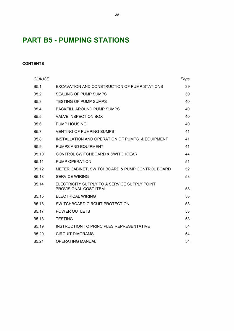
38
PART B5 - PUMPING STATIONS
CONTENTS
CLAUSE Page
B5.1 EXCAVATION AND CONSTRUCTION OF PUMP STATIONS 39
B5.2 SEALING OF PUMP SUMPS 39
B5.3 TESTING OF PUMP SUMPS 40
B5.4 BACKFILL AROUND PUMP SUMPS 40
B5.5 VALVE INSPECTION BOX 40
B5.6 PUMP HOUSING 40
B5.7 VENTING OF PUMPING SUMPS 41
B5.8 INSTALLATION AND OPERATION OF PUMPS & EQUIPMENT 41
B5.9 PUMPS AND EQUIPMENT 41
B5.10 CONTROL SWITCHBOARD & SWITCHGEAR 44
B5.11 PUMP OPERATION 51
B5.12 METER CABINET, SWITCHBOARD & PUMP CONTROL BOARD 52
B5.13 SERVICE WIRING 53
B5.14 ELECTRICITY SUPPLY TO A SERVICE SUPPLY POINT PROVISIONAL COST ITEM 53
B5.15 ELECTRICAL WIRING 53
B5.16 SWITCHBOARD CIRCUIT PROTECTION 53
B5.17 POWER OUTLETS 53
B5.18 TESTING 53
B5.19 INSTRUCTION TO PRINCIPLES REPRESENTATIVE 54
B5.20 CIRCUIT DIAGRAMS 54
B5.21 OPERATING MANUAL 54

39
PART B5 - PUMPING STATIONS
B5.1 EXCAVATION FOR AND CONSTRUCTION OF PUMP STATION/S
The Contractor shall obtain the approval of the Superintendent prior to constructing the pump station/s.
The Contractor shall construct and install Pump sumps, pumps, electrical connections, control switch gear, connecting pipework, valves, electrical control cabinets, pump housing, etc. as provided for in this specification and in the detailed drawings.
B5.1.1 Excavation and preparation of subgrade for pump sump
The Contractor shall be responsible for checking ground or pavement surface levels prior to ordering materials to ensure that the Pump Sump cover finishes above the surrounding ground or pavement surface as shown on the drawings.
The excavation for Pump Sump/s shall be the minimum uniform shaped excavation necessary to permit the installation of the pump sump and to allow external sealing of joints, pipe entries etc.
The floor of the excavation shall be level and free from loose or soft material prior to placing the bedding material. The bedding shall be a uniform compacted layer of 10mm screening of at least 100mm thickness placed over the whole of the excavation floor and shall be placed to the level of the underside of the pump sump base.
The Contractor shall have the Superintendent inspect the excavation prior to placing the bedding to determine whether additional treatment is required.
B5.1.2 Pump sump construction
Pump sump/s shall be as shown on the drawings and shall fully pre-cast and be manufactured in accordance with Clause B1.7.8.
On completion, the pumping sump/s shall be sealed to prevent the ingress of ground or storm water and the egress of collected effluent.
Holes cut in walls of pumping sumps to take inlet drain/s, transfer pipes, vents etc. shall be neatly machine cut to provide a uniform 15mm cavity around the pipes.
B5.2 SEALING OF PUMP SUMPS
B5.2.1 Circumferential joints
The circumferential joints on interlocking pipes forming the pump sump walls shall be sealed as specified in Clause B4.4.3, of this Specification.
The joint between the cover slab and the pump sump walls shall be sealed as for circumferential joints.
B5.2.2 Openings through pump station walls
All penetrations through the pump sump walls shall be sealed in accordance with clause B4.4.3 of this specification.

40
B5.3 TESTING OF PUMP SUMP/S
The pipes to the pump sump shall be sealed with stoppers and the pump sump filled to the top with water and allowed to stand for 24 hours, it shall then be topped up with water again and the drop in water level shall then not exceed 20mm in 24 hours. Water tests shall be witnessed by the Superintendent.
Where water loss exceeds this rate, the pump sump shall be emptied and the seals on all joints and entries resealed and cracked or defective sections of the pump sump repaired in a manner approved by the Superintendent and the chamber retested.
At the completion of the test the water shall be pumped from the sump.
The Contractor shall not backfill around the Pump Sump until the water test is complete unless otherwise approved by the Superintendent.
B5.4 BACKFILL AROUND PUMP SUMPS
The excavation around pump chambers shall be backfilled with sand compacted in accordance with Clause B3.7.3. Backfill Class 'B' of this specification.
B5.5 VALVE INSPECTION BOX
The Contractor shall provide and install a valve inspection box to house the valves from each pump unless otherwise shown on the detail drawings.
The valve box may be located adjacent the pump sump as a separate chamber or may be constructed as a chamber within the pump sump, cast as an integral part of the pump sump, and be sealed from the main pumping chamber.
The valve inspection box shall be constructed to the details and dimensions as shown on the design drawings or as approved by the Superintendent. The Contractor shall provide sleeves in the walls to allow for the entry and exit of any pipes through the walls. Such openings shall be no larger than 15mm greater than the size required, and shall be sealed as detailed in Clause B4.4.3. Backfill around Valve Boxes shall be as for pump sumps.
B5.6 PUMP HOUSING
The Contractor shall supply and install a pump shed to each pump station as required by and to the detail shown on the design drawings.
The Contractor shall allow in his tender to make application to the Council for development approval prior to construction of the pump sheds and shall pay all application fees. The application shall include supporting calculations of the shed design as required by Council.
No claims will be accepted for any alterations to the shed design that are required to meet the requirements of the relevant building codes.
The external surfaces of the pump shed shall be finished in "Colorbond" �Rivergum� steel cladding.
The shed shall be of the dimensions shown on the drawings with 2m head room and "Gable Roof" or equivalent.
The pump shed shall contain at least one (1) openable, louvred window with Galvanised steel blades and two (2) 600mm x 600mm fixed louvre, insect proofed vents at low level within the pump housing.

41
Gutters and downpipes shall be fitted to the shed, discharging as shown on the drawings.
Access to the pump shed shall be through a single sliding door. The door opening shall be at least 1200mm wide and 1800mm high.
Two (2) 240 volt, 2 x 36 watt fluorescent lights shall be supplied and fitted inside the pump shed, centrally and at third points along the pump housing.
The Contractor shall install a double 240 volt 10 amp, RCD protected, power outlet within the shed.
An external all weather and vandal proof light, "Phillips Vandal Light 18 watt" or similar shall be supplied and fitted centrally to the top of the pump shed, pump sump entry end.
The joint between the side cladding and the shed floor shall be sealed by construction of the floor after erection of the shed or alternatively the shed floor slab shall extend 75mm beyond the side cladding and the side cladding sealed to the floor slab with an approved coloured silicon sealant as approved by the Superintendent.
B5.7 VENTING OF PUMPING SUMPS
The Contractor shall supply and install, at each pumping sump, a 150mm internal diameter (unless otherwise shown on the detailed drawings) educt vent, prefabricated from heavy gauge steel pipe (5.4mm wall thickness), as shown on the detailed drawings, and hot dipped galvanised after manufacture.
The vent shall be located as shown on the plans, but not less than 3 metres from the pumping sump and shall extend 9 metres in height above the top surface of the pumping sump cover slab or as otherwise shown on the detailed drawings.
The vertical stack shall connect to the pumping sump with 150mm diameter uPVC pipe surrounded with cement concrete as shown on the detailed drawings.
B5.8 INSTALLATION AND OPERATION OF PUMPS AND EQUIPMENT
The Contractor shall allow for the installation of pumps, pumping equipment, pump housing, switchgear, control equipment, electrical wiring, pipework etc. as shown on the drawings, in accordance with the manufacturers requirements and conforming to this specification as follows;
B5.9 PUMPS AND EQUIPMENT
B5.9.1 General
Materials and equipment used must be able to give a long operating life with a minimum of maintenance under the prevailing conditions. Septic tank effluent presents a highly corrosive environment.
Each pump station shall be equipped with Two (2) pumps, each capable of full independent duty at the design flow and head.
B5.9.2 Submersible sewage pumps and motors
(a) General
Submersible pumps shall be of the sump base mounted type, with slide and lock system for connection to the delivery mains, and be provided with a Stainless Steel guide rails for raising and lowering the pumps.
42
The Pumps shall conform with the following performance requirements.
• The unit shall be able to operate over the full head range from full flow to no flow duties in either wet or dry well installation without overloading the motor. The cooling system shall be integral and adequate for all operating conditions.
• The unit shall operate in the vertical position.
• The pumps shall be suitable for the pumping of sewerage effluent without undue wear or corrosion to the casing, shaft, impeller or seals.
• The unit shall be resistant to the severe corrosion associated with septic tank effluent pumping stations and shall be lubricated sufficiently to allow long periods of operation without attention.
• Wear rings and seals should be constructed in such a manner as to preclude excessive wear from intrusive silt or grit.
• The pump shall be capable of passing a sphere not less than 38mm diameter or be of the cutter of shredder design.
• The pump installation shall be in accordance with the manufacturers recommendations and specifications and any deviation from the drawings and specification must be approved by the Superintendent.
• The pump shall be fitted with a moisture monitoring probe.
(b) Pump Motor
The motor shall be:
• designed for 415 volt 3 phase 50 Hertz electrical supply. Starting current shall not exceed six times the normal operating current. The motor shall be capable of not less than fifteen starts per hour without overheating.
• rated for non-overloading horsepower.
• totally enclosed oil immersed squirrel cage 50 Hz with dimensions in accordance with AS1360-10 1975 and performance in accordance with AS1359.
• water tight and of cast iron construction to at least AS GB-1962. Entry of water at the shaft shall be prevented by use of mechanical face seals installed in an oil filled chamber incorporating adequate pressure relief.
• fitted with an adequate length of cable and be completely sealed.
• the motor is to be fitted with 1000 ohm PTC thermistors.
(c) Pump Schedule
Refer to Drawings.
B5.9.3 Positive Displacement Pumps
(a) General
The pump installation shall be in accordance with the manufacturers recommendations and specifications and any deviations from the drawings and specifications must be approved by the Superintending Officer
The pumps shall conform with Clause B5.9.2 (a) as applicable to positive displacement pumps.
43
The pump and motor may be close coupled or belt driven to form a compact cost effective unit.
Internal Drive Mechanism
The rotor shall be driven by the drive shaft via two pin type universal joints connected by a rigid connecting rod. Each universal joint shall consist of a drive pin passing through a replaceable press fit wear bush in the end of the coupling rod and located in the rotor and the drive shaft extension heads also fitted with press fit wear bushes. Each pin shall be held in position by a rigid metallic sleeve. To ensure longevity the coupling rod operating angle should not be more than 1.7 degrees about the centre line.
Stator / Rotor
The stator material shall be suitable for use with sewage effluent and shall be injection moulded into a steel tube so that the stator material protrudes from each end to form a sealing bead which will prevent the pumped liquid from contacting the stator tube. The stator assembly shall be clamped between the inlet chamber and end cover by four tie-rods. The rotor shall be machined of stainless steel to BS 970 Grade 316s31 and covered with a hard facing chrome at least 0.25mm thickness.
Pump Body
The pump body, including any end cover, inlet chamber and drive body shall be of heavy duty cast iron. There shall be a boss on the inlet and outlet side of the pump body tapped for a gauge connection and/or for filling and emptying. An access opening shall be provided in each side of the inlet housing for stuffing box/seal maintenance. All cast parts shall be free of sand or blow holes and other defects.
Inlet and outlet connections shall be flanged to BS4504.
Drive Shaft Extension
The drive shaft shall be of a solid design and shall be fully machined with the section of the shaft passing through the seal being hard faced chrome plate having a minimum thickness of 0.25mm. The drive shaft shall be of ample size to transmit the maximum applied load without excessive deflection.
Mechanical Seal and Housing
A separate seal housing manufactured from heavy duty cast iron shall be provided and fitted with bosses to enable greasing connections to be fitted when necessary. The seal shall be a carbon/ceramic/nitrite mechanical seal.
(b) Electric Motors
Electric motors shall be totally enclosed, fan cooled, squirrel cage 50 hertz with dimensions in accordance with AS1017-1971 (metric) and performance in accordance with BS 2613-1970 (metric) unless otherwise approved or specified.
All motors shall comply with the latest relevant standard.
The motor shall be capable of not less than fifteen starts per hour without overheating.

44
Rated for starting torque.
The motor is to be fitted with 1000 ohm PTC thermistors.
(c) Pump Schedule
Refer to Drawings.
B5.9.4 Pump Bases and Beds (Above Ground Pumps)
The pumps shall be mounted on a heavy duty channel base hot dipped galvanised after manufacture in accordance with the provisions of clause B1.2.6.
The Contractor shall mount the pumps and channel base on a reinforced concrete plinths, at least 150mm in thickness, complete with holding down bolts and nuts in accordance with the manufacturers recommendations. The concrete plinths shall extend 150mm beyond the full length and width of the pump and motor mounting base or as otherwise shown on the drawings. The plinth reinforcement shall be tied in to the pump shed floor or cover slab.
B5.10 CONTROL SWITCHBOARD AND SWITCHGEAR
B5.10.1 General
The Contractor shall supply and install the switchboard and switchgear and all associated wiring complying with this specification, Australian Standard Wiring Rules AS 3000, AS 1939 and AS 1136 and shall conform to the requirements of the Electricity Trust of South Australia (ETSA). The switchboard and switchgear shall be suitable for connection to a 415 volts, 50 hertz, 3 phase 4 wire system.
The switchboard shall be an enclosed type, front connected, dust proof and moisture proof, minimum IP54, constructed as detailed in the drawings.
All push button selector switches etc., which are to be normally operated shall be accessible from the front. Covers to be removable without disturbing wiring to equipment. Hinged control panels may be used
It shall be possible to operate all control gear selector switches etc., and to read all meters etc., without the removal of covers, or exposure to live parts within the switchboard.
Power circuit breakers shall be arranged for operation without the removal of covers etc.
Switchboard construction and schematic wiring diagrams shall be submitted for approval before manufacture is commenced. Approval of the wiring diagrams by the Superintendent does not release the Contractor from his obligations under this Contract to ensure that the pumps operate in accordance with the requirements of this specification.
B5.10.2 Control Equipment
Where the functions of the pumping system as described in this specification are controlled by Programmable Logic Control (PLC) the Contractor shall allow in the tender price to provide the Superintendent with a copy of the control function program for inclusion in the Operation Manual. The control function program shall be written to allow access by other than the control equipment manufacturer and be capable of function adjustment.

45
All Control equipment shall be year 2000 compliant.
The Controls shall comprise the following equipment:
One (1) Three phase isolator switch
Two (2) Direct on-line contactors fitted with suitably rated three pole ambient temperature compensated thermal overload relays having positive single phasing protection characteristics.
One (1) 240/24 volt control transformer.
Two (2) Hour run indicators
Two (2) Pump control "Manual - Off - Auto" single pole rotary switches.
One (1) Duty Time Delay Relay.
One (1) Alternate Duty step relay.
One (1) Alarm cancel push button.
One (1) Reset push button
One (1) Pilot light for each alarm condition
One (1) Lamp test switch (To include testing of all pilot and alarm warning lights)
One (1) Terminal strip to be provided for the termination of level regulator cables and wiring to all external equipment.
Control and Fault Relays for:
(a) High level
(b) Thermal/Current overload - Pump 1 Thermal/Current overload - Pump 2
(c) High pressure - Pump 1 (Positive Displacement pump only) High pressure - Pump 2 (Positive Displacement pump only)
(d) Low level (Float Controls Only)
(e) Thermistor - Pump 1 (motor winding temperature) Thermistor - Pump 2 (motor winding temperature)
(f) No Flow - Pump 1 (Positive Displacement pump only) No Flow - Pump 2 (Positive Displacement pump only)
(g) Moisture Probe - Pump 1 (Submersibles pump only) Moisture Probe - Pump 2 (Submersibles pump only)
(h) Cyclic Fault - Pump 1 Cyclic Fault - Pump 2
The fault relays are required to perform the functions outlined in Clause B5.10.4 and B5.10.5.

46
Each alarm output shall have an associated pair of potentially free normally open contacts for connection to the Remote Alarm Monitoring System.
Red pilot lights (Static or Flashing or combination of both) to indicate:
(a) High Level
(b) Thermal/Over current - Pump 1 Thermal/Over current - Pump 2
(c) High Pressure - Pump 1 High pressure - Pump 2
(d) Low level
(e) Thermistor - Pump 1 Thermistor - Pump 2
(f) No Flow - Pump 1 No Flow - Pump 2
(g) Moisture Probe - Pump 1 Moisture Probe - Pump 2
(h) Cyclic Fault - Pump 1 Cyclic Fault - Pump 2
Green pilot lights to indicate:
(a) Power On (b) Pump 1 � Operating (c) Pump 2 - Operating
Controls to be accessible from front cover:
Reset Push Button Control switch (Man-Off-Auto) for each pump Alarm cancel button Separate Pilot lights for each alarm condition Hour run meters (reading 10,000 hours with 1/10 hour increments) Lamp test switch for external alarm warning light and all Pilot lights.
B5.10.3 Level Control Switches
Level control switches shall be "mercury float" type of the fully sealed bulb style, or "Multi-Trode" 2.0/10 multi sensored probe or equal approved control switching mechanisms, installed in accordance with the drawings.
Where individual float or probe level controllers are used provision shall be made in the level control cables for alteration of the operating levels by plus or minus 1800mm.
B5.10.4 Control and Alarm Systems
The control and alarm system shall have the following protection measures:-

47
(a) High Level
High level indication shall be provided.
The high level switch, if operated shall energise a relay, and activate the alarm. A pilot light will be energised. The alarm shall remain active until cancelled manually by the alarm cancel function. System reset will be required. The high level alarm shall shut down the operating pump and the stand-by pump shall assume full duty.
(b) Thermal Current Overload
Thermal current overload protection shall be provided.
Each Thermal Overload relay, on over current shall energise a fault relay, activate the alarm and stop the respective pump. A pilot light will be energised. Duty shall transfer to the stand-by pump. The alarm shall remain active until cancelled manually by the alarm cancel function. System reset will be required.
The thermal current overload relay shall be set to suit the running current of the motor but in no circumstances shall it be greater than the full load current of the motor.
WARNING: Over current protection shall not be omitted when over-temperature protection is provided
(c) Over Temperature Protection
Motor over temperature control (thermistor) shall be provided.
Over Temperature shall energise a fault relay, activate the alarm and stop the respective pump. A pilot light will be energised. Duty shall transfer to the stand-by pump. The alarm shall remain active until cancelled manually by the alarm cancel function. System reset will be required
(d) No Flow Protection
Where it is required that No Flow Protection be provided (Refer Clause B5.10.5) a limit switch and time delay relay shall be installed for each pump. Additional fault relays and pilot lights will be provided. The time delay relay will override no flow during start up
No Flow shall energise a fault relay, activate the alarm and stop the respective pump. A pilot light will be energised. Duty shall transfer to the stand-by pump. The alarm shall remain active until cancelled manually by the alarm cancel function. System reset will be required.
(e) Seal Check Protection
Where it is required Seal Check protection be provided, (Refer Clause B5.10.5) a liquid detection relay is to be installed for each pump. Additional fault relays and pilot lights will be provided.
Seal Failure shall energise a fault relay, activate the alarm and stop the respective pump. A pilot light will be energised. Duty shall transfer to the stand-by pump. The alarm shall remain active until cancelled manually by the alarm cancel function. System reset will be required.

48
(f) High Pressure Protection
Where it is required that High Pressure protection shall be provided, (Refer Clause B5.10.5) a pressure switch is to be installed for each pump. Additional fault relays and pilot lights will be provided
High Pressure shall energise a fault relay, activate the alarm and stop the respective pump. A pilot light will be energised. Duty shall transfer to the stand-by pump. The alarm shall remain active until cancelled manually by the alarm cancel function. System reset will be required.
(g) Low Level Protection (For Float Type level Controllers only)
Where it is required that Low Level protection be provided, (Refer Clause B5.10.5) a low level control switch shall be installed. An additional fault relay and pilot light will be provided.
Low Level shall energise a fault relay, activate the alarm and shut down the pumps. A pilot light will be energised. The alarm shall remain active until cancelled manually by the alarm cancel function. System reset will be required.
(h) Cyclic Protection
Cyclic fault protection shall be provided to ensure that the number of pump starts per hour do not exceed the pump manufacturers recommendations.
Cyclic fault shall energise a fault relay, activate the alarm and stop the respective pump. A pilot light will be energised. Duty shall transfer to the stand-by pump. The alarm shall remain active until cancelled manually by the alarm cancel function. System reset will be required
(i) Remote Alarm Monitoring System
The Contractor shall supply, install, program and commission a solid state automatic alarm dialler capable of monitoring and reporting alarm conditions at the pump station/s.
The remote monitoring system shall comprise:
One (1) EDAC Model 222, Automatic Alarm Dialler, with user recordable voice message facility and phone list, back up battery power supply, and FAX GUARD Transient Protection unit.
A user programmable seven day 24 hour time clock, with battery back up, shall be incorporated into the auto-dialler non critical alarm input to allow for delay of alarm reporting to times allocated and determined by the Principal.
The alarm dialler and timer shall enable the following operations to occur:
i. The immediate reporting of all Critical Alarm conditions.
ii. Non Critical alarm conditions to be reported either immediately or delayed to times predetermined by the Principal. Initially this function shall be set to report non critical alarms during normal business hours five days a week pending further instruction from the Principal
iii. The phone number list shall dial sequentially until answered and cancelled. Cancellation shall be by operation of tone key on phone.
49
iv. All voice messages, phone number lists, dialler operations and time clock shall be fully programmable by the Principal
All alarms from each system shall be configured into two (2) common auto-dialler inputs as required by this specification and in accordance with the following:
Critical Alarms
High level in pump station Mains power failure - if still present after adjustable delay (0 to 30 minutes) Low level in pump station (if applicable)
Non Critical Alarms
Thermal/Current overload - all pumps Thermistor over load - all pumps Low Voltage Backup Battery Cyclic Fault Seal Probe - all pumps (if applicable) High Pressure - all pumps (if applicable) No Flow - all pumps (if applicable)
All alarm conditions shall be automatically dialled to a group of at least four (4) pre-defined telephone numbers. Numbers shall be dialled sequentially in order until answered and cancelled using telephone tone keys.
A pre-recorded voice message shall be provided for Critical or Non-critical alarm conditions and shall include the following:
• pump station site identification.
• nature of alarm ( ie. critical or non-critical) and,
• for critical alarms advice that urgent attention is required.
The auto dialler shall be compatible with both DTMF and Decadic telephone systems.
Battery backup shall maintain full system operation for at least four hours without mains power and retain programming and voice recordings for at least 48 hours without mains power.
All components associated with the Automatic Alarm Dialler shall be installed with-in the main control cabinet.
Three copies of all manuals shall be provided to the Superintendent, for the Remote Alarm Monitoring system and shall include, full workshop manuals and user handbooks for each component, as installed wiring and interconnection diagrams, full details of programming and alarm messages and recommended maintenance procedures
The Contractor shall allow for the arrangement of all services and works associated with the provision of a telecommunication exchange line and power to the auto dialling facility.
The telecommunications line should be DTMF ("tone dialling") if available. The application for the service shall be made in the name of the Principal.

50
The Principal shall pay all fees and costs associated with the provision of a telecommunication service to the Control cabinet.
(j) Identification
Engraved labels are to be provided to identify all equipment, switches, pilot lights etc. Where a single pilot light is used to indicate two alarm conditions the label shall clearly identify and correlate the status of the warning light to the specific alarm condition.
All terminals and wiring shall be identified and conform to the wiring diagram.
(k) Direct On-line Starting
Where the rating of the pump motor exceeds that allowed for direct-on-line starting by the supply authority reduced voltage starting shall be provided.
It is the responsibility of the Contractor to ensure that the starting torque on reduced voltage starting is adequate to start and accelerate the pump.
(l) Provision for Manual Control
Provision shall be made to run the pumps under manual control.
WARNING: The manual control shall only override the pump start function, all other control and fault systems shall continue to operate.
Alternatively manual operation shall be controlled by a timing device to limit operation of the pump in conditions of low sump level beyond the recommendations of the pump manufacturer.
(m) Alarm System Reset
The alarm cancel function shall be wired so that when the alarms are isolated, the defaulting pump cannot be started until a manual system reset is performed.
(n) Alarm Warning
In addition to any requirements for Remote Alarm Monitoring the alarm system, in the event of a fault is required to activate a 240 volt 40 watt weatherproof light, fitted with a red (impact resistant) polycarbonate well-glass, located as indicated on the drawings or as otherwise directed by the Superintendent.
B5.10.5 Summary of Equipment Schedule
The Contractor shall include the following protection equipment in accordance with this specification, as detailed and as follows:
(a) No Flow (insert pump station number/s as applicable)
(b) Seal Check (insert pump station number/s as applicable)
(c) High Pressure (insert pump station number/s as applicable)
(d) Low Level (insert pump station number/s as applicable)
All associated wiring and equipment shall be integrated with the basic control and alarm system.

51
B5.11 PUMP OPERATION
The performance of the completed pumping system may be managed using a programmable Logic Controller having sufficient input and output modes to allow the pumping system to operate in accordance with this specification and as follows:
a. Automatic start of each pump alternately on each consecutive call by the level control regulator, and be capable of individual automatic operation exclusively when desired by the Principal. The Start controller shall be set at the level indicated on the drawings.
b. Automatic stop of the operating pump on call from the level control regulator. The Stop controller shall be set at the level indicated on the drawings.
c. The high level, Level control regulator shall activate the alarm when the liquid level is above the limit shown on the drawings.
d. The thermal overload relay shall detect the running current of the motor and ensure that the operating pump does not operate when over-current is detected.
e. The thermistor relay shall detect over-temperature within the motor casing and ensure that the operating pump does not operate when over temperature is detected.
f. (i) Where required, a no flow switch activated by the non-return valve shall ensure that the operating pump does not operate for a duration greater than that recommended by the pump manufacturer when there is no flow.
(ii) Where required, a seal check relay shall detect the ingress of water within the lower motor casing and ensure that the operating pump does not operate when moisture is detected.
(iii) Where required, a high pressure switch in the pump discharge main shall ensure that the operating pump does not operate above a pressure set by the Superintendent.
(iv) Where required, a low level float switch shall ensure that both the pumps are shut down and do not operate when the liquid level falls below the limit shown on the drawings.
g. In the event of a fault, the operating pump shall automatically cease operation, and the alarm will be activated. The respective fault indicator shall be illuminated. The stand-by pump shall assume normal duty, excepting in the case of low level shutdown. (Refer also clause B.5.10.4)
h. A time delay relay shall ensure that the on/off operation of either pump cannot be more frequent than 15 starts per hour. (Refer clause B5.10.4)
i. Controls shall be provided for isolation, automatic or manual stop/start operation for commissioning, inspection and maintenance purposes. (Refer Clause B5.10.4 (l) for conditions for manual control)
WARNING: The pumps shall be wired in such a manner that at no time shall both pumps operate together under automatic or manual operation.

52
B5.12 METER CABINET, SWITCHBOARD AND PUMP CONTROL BOARD
B5.12.1 General
Where the pumps are not housed in a shed the Contractor shall supply and install a free-standing meter and control switchgear cabinet for each pumping station, located as shown on the drawings.
The Cabinet shall be a two (2) section unit, the top section (the main switchboard) shall contain the Supply Authority meters, the main supply switch and circuit protection, the lower section the pump control board and switchgear.
B5.12.2 Construction
The cabinet shall be weather proof, IP56D fabricated from 1.6mm galvanised sheet steel fully folded and welded and constructed in accordance with the drawings. Provide a hot dipped galvanised, steel angle iron base bolted to the underside of the cabinet, to form a solid fixing to the concrete plinth as shown on the drawings.
The doors will be of the hinged lift off type and provided with lockable "Tee" handles. Two keys shall be provided for each lock. The locks for all cabinets shall be keyed alike, Metering sections as approved by the supply authority (ETSA Key Code ES) and control board sections, key code 604.
Each door shall restrained from fully opening by a removable chain or other approved device.
A sun shield, and ventilation louvres with replaceable filters and insect screens shall be provided. Dust-proofing seals shall be of a neoprene air cushion type, cemented to the cabinet return.
The entire unit shall be degreased before multi etch primer is applied. This will be followed by one coat of undercoat, and two coats of high gloss finish paint. The paint colour shall be �Rivergum� unless otherwise selected by the Superintendent.
The cabinet shall be of sufficient dimensions to house the supply metre and all the control equipment.
B5.12.3 Metering Section
The contractor shall supply and fit a double hinged insulation panel within the top section to the supply authorities requirements including suitably rated Main switch, Sub Circuit Breakers and Neutral and earth links.
B5.12.4 Pump Control Section
The Contractor shall supply and fit an internally hinged panel to the lower section for switchgear and control equipment, indicated for the operation of the pumps. Provide a removable equipment plate behind to accept switchgear.
The Contractor shall supply and fit all switchgear and control equipment for the operation of the pumps in accordance with this specification.
B5.12.5 Meter and Control Cabinet in Pump Shed
Where a pump shed is required to house the pumps the supply Authority meter cabinet shall be mounted on the external surface of the shed in the location indicated on the drawings. The main pump control cabinet shall be mounted inside the shed opposite the meter cabinet

53
B5.13 SERVICE WIRING
The Contractor shall install service wiring from the ETSA service supply point to the meter provided by ETSA.
For the purpose of tendering the Contractor shall allow a maximum length of 20m of service wiring for each pumping station.
B5.14 ELECTRICITY SUPPLY TO A SERVICE SUPPLY POINT
The Contractor shall make all applications and arrangements for the supply of electricity from the main to the service supply point with the power service provider.
The application for supply shall be made in the name of the Principal.
The Principle shall pay all fees and costs to the service provider associated with the provision of power to the service supply point.
B5.15 ELECTRIC WIRING
The Contractor shall supply and install all electric wiring necessary for the proper operation of the complete pumping systems, switchgear and controls. The switchgear and controls shall be mounted as indicated on the drawings and/or as directed by the Superintendent.
All wiring, electrical equipment and installation shall be in accordance with Australian Standard AS3000 and the Supply Authority service rules.
B5.16 SWITCH BOARD CIRCUIT PROTECTION
A main switch, motor, control, general power outlet and light sub circuit protection shall be provided. Neutral and earth links of suitable capacity are required.
Sub circuit protection shall be via suitably rated miniature circuit breakers. It is the responsibility of the Contractor to determine the rating of the circuit breakers to suit the installation and motor starting capacity.
B5.17 POWER OUTLETS
The Contractor shall install a double 240 volt 10 amp, RCD protected, power outlet within each metering and control switchgear cabinet or pump shed as applicable.
B5.18 TESTING
The Contractor shall be responsible for all testing necessary to establish with the Superintendent that the pumping installation performs as required by this Specification in all possible operating modes and sequences.
Testing shall include the provision of fresh water for the filling of rising mains and the pump chambers, the measurement of operating pressure at the pump outlet and the recording of draw down rates in the pump sump to establish pump performance.
If the test operation does not meet the specified performance for the installation as a whole or any part, the installation shall be rectified and further tests shall be carried out to the satisfaction of the Superintendent at no extra cost to Principal.
On the successful completion of the testing at the installation the Contractor shall provide the Superintendent with a certification by a Qualified Electrician confirming that the installation conforms with the requirements of the Electricity Supply Authority.

54
B5.19 INSTRUCTION OF THE PRINCIPLES REPRESENTATIVE
Following acceptance of the tested pump stations the Contractor shall allow in his tender to provide instruction to the Principle's Representative in the use and operation of the pumping system.
B5.20 CIRCUIT DIAGRAMS
An approved circuit diagram in a waterproof clean plastic envelope shall be attached to the inside of the switch cabinet.
B5.21 OPERATING MANUAL
The Contractor shall provide, to the Superintendent, Three copies of an operating manual, which shall provide details relative to each pump station. This information to be provided in full detail is to be categorised as follows:
(a) Introduction (b) Start up Procedures (c) Alarm Conditions (d) Components (e) Installation, dismantling and re-assembly procedures (f) Testing (g) Operation (h) Maintenance Instructions (i) Fault List (symptom, cause and action) (j) Wiring Diagrams. (In addition to the requirements of Clause B5.19)

55
PART B6 - OXIDATION AND EVAPORATION LAGOONS
The following are suggested headings indicating areas that may be considered when preparing the technical specifications for the Oxidation and Evaporation Lagoons.
CONTENTS
CLAUSE Page
B6.1 CLEARING THE SITE
B6.2 EXCAVATION
B6.3 FILLING AND BANK FORMATION
B6.4 SELECTION AND HANDLING OF MATERIALS
B6.5 COMPACTION
B6.6 GRADING OF RETAINING WALLS
B6.7 TESTING
B6.8 MACHINERY REQUIREMENTS
B6.9 SEALING OF FLOOR AND EMBANKMENTS
B6.10 EMBANKMENT PROTECTION
B6.11 EXCESS SOIL
B6.12 INLET, OUTLET AND TRANSFER STRUCTURES
B6.13 DIVERSION FENCING
B6.14 PERIMETER FENCING

56
PART B6 - OXIDATION AND EVAPORATION LAGOONS
This part of the technical specification shall be prepared directly by the design consultant to reflect the details obtained from geotechnical investigation of the site and should include but not be limited by:
• site clearing,
• embankment construction,
• preparation of surfaces below embankments,
• embankment formation,
• construction tolerances,
• sources of materials for floor and embankment construction,
• compaction density of embankments, floor and lining,
• compaction testing -(provisional cost sum),
• machinery requirements,
• lagoon floor and embankment sealing,
• embankment protection requirements,
• treatment of external embankment faces,
• handling of surplus soil,
• inlet, outlet and transfer structures etc
• diversion fencing,
• perimeter fencing,
Diversion fencing within the lagoon and perimeter fencing of the lagoon and evaporation pans should be to at least the following standard.
Lagoon Diversion Fence
Diversion fencing shall be "Type B" clad in Glass Fibre Reinforced Polyester (G.R.P.) corrugated sheet, in accordance with the detail shown on the design drawings and to a standard provided for in Clause B1.12.2 "Fencing".
Perimeter Fence
(a) Oxidation Lagoon
Provide and erect a 1.830 metre high galvanised chain wire mesh fence with galvanised posts around the oxidation lagoon site as shown on the design drawings.
All posts are to be fitted with a suitable cap.
Gate Posts - 63mm internal diameter medium duty, galvanised water pipe.
Corner and End Posts - 50mm internal diameter medium duty galvanised water pipe.
Intermediate Spacing
Posts - (3m maximum spacings) 40mm internal diameter medium duty galvanised water pipe.

57
Chain Wire Mesh - 1.830m high 10 gauge x 50mm galvanised mesh
Gates - 1 pair 1.830m x 1.830m to form a 3.66m opening and fitted with one way gate catch and lock. Padlock to be supplied with gates. (Lockwood 234 or similar with a solid brass body.)
(b) Evaporation Pans
Provide and erect a 1.200 metre high galvanised ring lock fence around the evaporation pan site as shown on the plans.
All gate, corner and end posts to be as for Oxidation Lagoon fence
All intermediate posts shall be timber posts. (ie. Treated Radiata Pine)
Ringlock Mesh - 900 wide galvanised cyclone mesh.
Barbed Wire - Galvanised barbed wire.
Gates - 1 gate 1.200 metres high x 4.000 metres wide stock gate with galvanised chain mesh infill (50mm) fitted with one way gate catch and lock. Padlock to be supplied with gate. (Lockwood 234 or similar with solid brass body, keyed to match the lock required for the Lagoon gates).

58
PART C
GEOTECHNICAL INVESTIGATIONS FOR
THE CONSTRUCTION OF
A SEPTIC TANK EFFLUENT DISPOSAL SCHEME
AT (name of town) ................................................................................................................
STED NUMBER (scheme number) .....................................................................................
FOR THE DISTRICT COUNCIL OF (name of Council),
........................................................................................................... SOUTH AUSTRALIA
DATE (day) ...................................... (month) ....................................... (year) ...................
NAME (name of Consultant)..................................................................................................
ADDRESS (address of Consultant) .......................................................................................
...............................................................................................................................................