Embed Size (px)
Citation preview

CSM_E2E_DS_E_12_4
1
Standard Proximity Sensor
E2E Your Search for Proximity Sensors Starts with the World-leading Performance and Quality of the E2E• Standard Sensors for detecting ferrous metals.• Wide array of variations. Ideal for a variety of applications. • Models with different frequencies are also available to prevent
mutual interference.• Superior environment resistance with standard cable made of oil-
resistant PVC and sensing surface made of material that resists cutting oil.
• Useful to help prevent disconnection. Cable protector provided as a standard feature.
Features
Pre-wired Models with Oil-resistant Reinforced PUR Cables Added to the Lineup and Easy Differentiation with Orange Head
Lineup includes models with Smartclick pre-wired connectors for fast connection.
UL-recognized Models Available
For the most recent information on models that have been certified for safety standards, refer to your OMRON website.
(Standards do not apply to all models.)
Be sure to read Safety Precautions on page 25.
2-Wire Models
Oil Resistanceil Resistance Cable Flexibilityable FlexibilityCable FlexibilityCable Flexibility at able Flexibility at Low Temperatures Low Temperatures
Oil Resistance (Insulation service life):twice or three times that of oil-resistant vinyl chloride
Cable Flexibility:approximately twicethat of vinyl chloride cables
More Flexibility at −40°C
Oil ResistanceCable Flexibility at Low Temperatures
Differentiation from standard models: Orange Head
XS5 Smartclick connectors used to enable checking connector mating
Jacket: Polyester elastomer
Insulation: Oil-resistant grade PUR (polyurethane)1/8 turn
Insert all the way.
Cl ick

E2E
2
Lineup includes models with self-diagnostic output to provide notification of failures and unstable detection conditions, such as coil burnout.• Contributes to preventive maintenance to keep the line from stopping.
Reduced wiring, fewer resources, and low power consumption contribute to environmentalism. • Wiring work and amount of copper wire used reduced to two thirds of that required for 3-wire models. • Current consumption drastically reduced to less than 10% (when a DC 2-wire model is compared with a DC 3-wire model).
Wide range of ambient operating temperatures: −40°C to 85°C (M8 to M30 models)• Suitable for low-temperature and high-temperature applications, which are troublesome for photoelectric sensors.
Lineup includes models with flexible cable (M8 to M30 models)• Reduced risk of disconnection in applications with moving parts.
3-Wire Models

3
E2E
E2E Guide to Selection by Purpose
Environment
Maintenance
Reducing troubles Higher oil resistance
Easy replacement
Reducing stocked models
Wide operating temperature range
Resists the influence of surrounding metal
Mutual interference prevention
Miswiring measures
Early discovery of problems
AC/DC 2-Wire ModelsE2E-X@T1
Connector ModelsE2E-X@D@-M1(G)E2E-X@E@-M1E2E-X@Y@-M1
Pre-wired Connector ModelsE2E-X@D1-M1(G)J-(T)
Smartclick Pre-wired Connector ModelsE2E-X@D@-M1TGJ-(U)/(US)
Models with Oil-resistor reinforced PUR cable E2E-X@D@-U
Models with a Different Frequency (NO Models only)E2E-X@@15
DC 2-Wire ModelsE2E-X@D@DC 3-Wire ModelsE2E-X@E@
DC 2-Wire No-polarity ModelsE2E-X@D1-M1J-T
Diagnostic ModelsE2E-X@D1S
−40 to 85°CAC 2-wire: M12 to M30, DC 3-wire: M8 to M30
−25 to 70°CModels not listed above.
Shielded Models
DC 2-Wire ModelsE2E-X@D@
NPN/PNP output
AC/DC
Load short-circuit protection
No polarity
Mounting to moving parts Robotics Cable Models
E2E-X@D1-RE2E-X@E1-RRobotics cable
Note: Refer to Models Not Listed in this Catalog for Long Body Models, Transmission Couplers, and Power Couplers.
Reinforced
Standard Models with Oil-resistant PVC cable

E2E
4
E2E Model Number Legend
Note: The purpose of this model number legend is to provide understanding of the meaning of specifications from the model number. Models are not available for all combinations of code numbers.
No. Classification Code Meaning RemarksA Appearance X Cylindrical (threaded)
B Sensing distanceNumber Sensing distance (Unit: mm) Example:
1R5: 1.5 mmR Indication of decimal point
C ShieldingBlank Shielded Model
M Unshielded Model
DPower supply and output specifications
B DC 3-wire PNP open-collector output
Whether D models have polarity is defined by num-ber J.
C DC 3-wire NPN open-collector outputD DC 2-wire polarity/no polarityE DC 3-wire NPN collector load built-in output F DC 3-wire PNP collector load built-in output T AC/DC 2-wireY AC 2-wire
EForm of output switching el-ement
1 Normally open (NO)2 Normally closed (NC)
F Oscillation frequency typeBlank Standard frequency Used to prevent mutual in-
terference.5 Different frequency
G Self-diagnosisBlank No
5 Yes
H Connection method
Blank Pre-wired
M1 M12-size metal connector
M3 M8-size metal connector
I Connector specifications
BlankConnector ModelDC 3-wire and AC 2-wire, DC 2-wire with self-diagnosis output, DC 2-wire with old pin arrangement
G Connector ModelDC 2-wire with IEC pin arrangement
J Pre-wired Connector ModelDC 3-wire and AC 2-wire, DC 2-wire with old pin arrangement
GJ Pre-wired Connector ModelDC 2-wire with IEC pin arrangement
TJ Pre-wired Smartclick Connector ModelDC 2-wire
TGJ Pre-wired Smartclick Connector ModelDC 2-wire with IEC pin arrangement
J DC 2-wire polarityBlank Polarity
T No polarity
K Cable specificationsBlank Standard PVC cable (oil resistant)
R Flexible PVC cable (oil resistant)U Polyurethane cable (oil resistant and reinforced)
L
New model N New model (Applies only to DC 2-wire pre-wired and shielded models.)
This is blank if the cable specification in number K is R or U.
Standard-certified model US UL-recognized model (Applies to DC 2-wire pre-wired models and pre-wired connector models.)
M Cable length Letter M Cable length (Unit: m) (Applicable to Pre-wired Models and Pre-wired Connector Models.)
Example:2M0.3M
E2E- A B C D E F G H- ML-- - KJI
5
E2E
Ordering Information
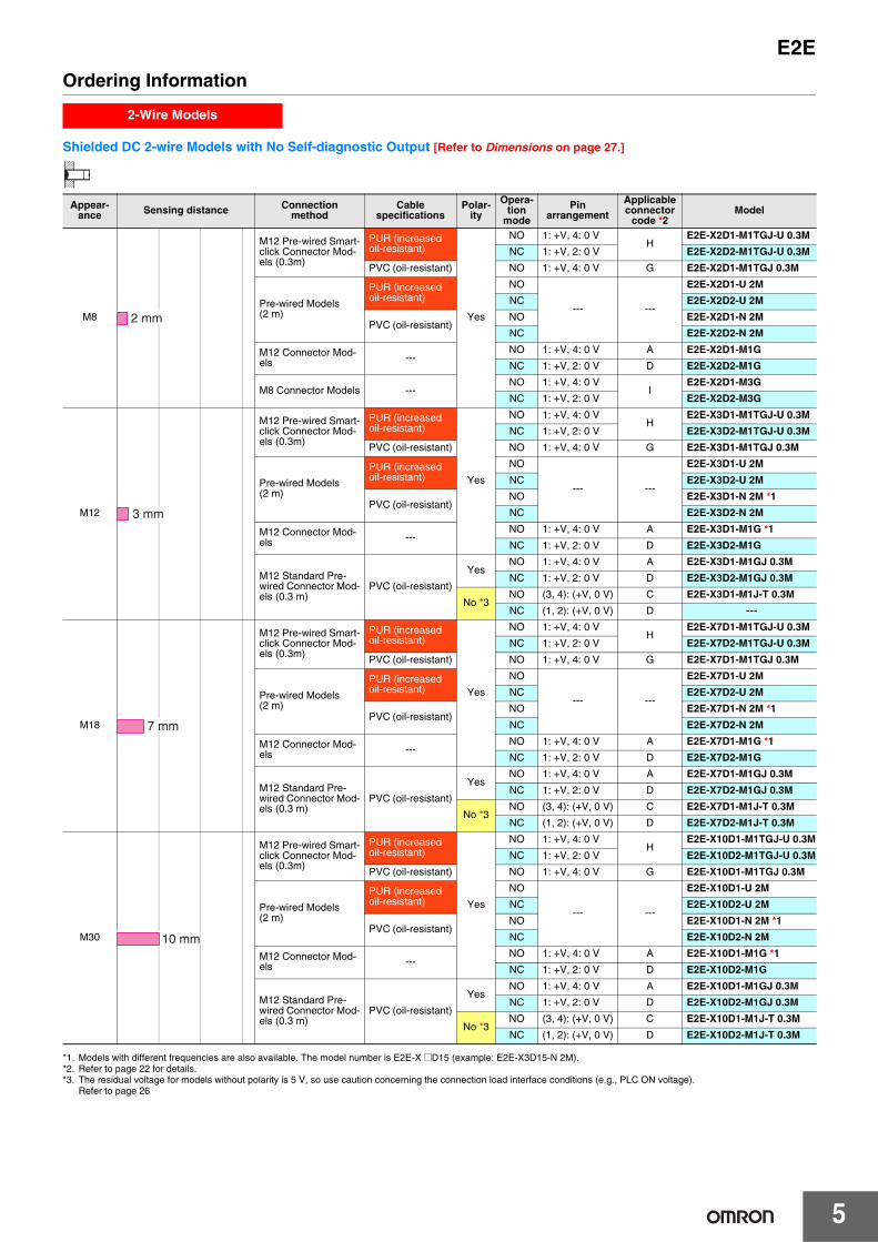
Shielded DC 2-wire Models with No Self-diagnostic Output [Refer to Dimensions on page 27.]
*1. Models with different frequencies are also available. The model number is E2E-X @D15 (example: E2E-X3D15-N 2M).*2. Refer to page 22 for details.*3. The residual voltage for models without polarity is 5 V, so use caution concerning the connection load interface conditions (e.g., PLC ON voltage).
Refer to page 26
2-Wire Models
Appear-ance Sensing distance Connection
methodCable
specificationsPolar-
ity
Opera-tion
mode
Pin arrangement
Applicable connector
code *2Model
M8
M12 Pre-wired Smart-click Connector Mod-els (0.3m)
PUR (increased oil-resistant)
Yes
NO 1: +V, 4: 0 VH
E2E-X2D1-M1TGJ-U 0.3M
NC 1: +V, 2: 0 V E2E-X2D2-M1TGJ-U 0.3M
PVC (oil-resistant) NO 1: +V, 4: 0 V G E2E-X2D1-M1TGJ 0.3M
Pre-wired Models (2 m)
PUR (increased oil-resistant)
NO
--- ---
E2E-X2D1-U 2M
NC E2E-X2D2-U 2M
PVC (oil-resistant)NO E2E-X2D1-N 2M
NC E2E-X2D2-N 2M
M12 Connector Mod-els ---
NO 1: +V, 4: 0 V A E2E-X2D1-M1G
NC 1: +V, 2: 0 V D E2E-X2D2-M1G
M8 Connector Models ---NO 1: +V, 4: 0 V
IE2E-X2D1-M3G
NC 1: +V, 2: 0 V E2E-X2D2-M3G
M12
M12 Pre-wired Smart-click Connector Mod-els (0.3m)
PUR (increased oil-resistant)
Yes
NO 1: +V, 4: 0 VH
E2E-X3D1-M1TGJ-U 0.3M
NC 1: +V, 2: 0 V E2E-X3D2-M1TGJ-U 0.3M
PVC (oil-resistant) NO 1: +V, 4: 0 V G E2E-X3D1-M1TGJ 0.3M
Pre-wired Models (2 m)
PUR (increased oil-resistant)
NO
--- ---
E2E-X3D1-U 2M
NC E2E-X3D2-U 2M
PVC (oil-resistant)NO E2E-X3D1-N 2M *1
NC E2E-X3D2-N 2M
M12 Connector Mod-els ---
NO 1: +V, 4: 0 V A E2E-X3D1-M1G *1
NC 1: +V, 2: 0 V D E2E-X3D2-M1G
M12 Standard Pre-wired Connector Mod-els (0.3 m)
PVC (oil-resistant)
YesNO 1: +V, 4: 0 V A E2E-X3D1-M1GJ 0.3M
NC 1: +V, 2: 0 V D E2E-X3D2-M1GJ 0.3M
No *3NO (3, 4): (+V, 0 V) C E2E-X3D1-M1J-T 0.3M
NC (1, 2): (+V, 0 V) D ---
M18
M12 Pre-wired Smart-click Connector Mod-els (0.3m)
PUR (increased oil-resistant)
Yes
NO 1: +V, 4: 0 VH
E2E-X7D1-M1TGJ-U 0.3M
NC 1: +V, 2: 0 V E2E-X7D2-M1TGJ-U 0.3M
PVC (oil-resistant) NO 1: +V, 4: 0 V G E2E-X7D1-M1TGJ 0.3M
Pre-wired Models (2 m)
PUR (increased oil-resistant)
NO
--- ---
E2E-X7D1-U 2M
NC E2E-X7D2-U 2M
PVC (oil-resistant)NO E2E-X7D1-N 2M *1
NC E2E-X7D2-N 2M
M12 Connector Mod-els ---
NO 1: +V, 4: 0 V A E2E-X7D1-M1G *1
NC 1: +V, 2: 0 V D E2E-X7D2-M1G
M12 Standard Pre-wired Connector Mod-els (0.3 m)
PVC (oil-resistant)
YesNO 1: +V, 4: 0 V A E2E-X7D1-M1GJ 0.3M
NC 1: +V, 2: 0 V D E2E-X7D2-M1GJ 0.3M
No *3NO (3, 4): (+V, 0 V) C E2E-X7D1-M1J-T 0.3M
NC (1, 2): (+V, 0 V) D E2E-X7D2-M1J-T 0.3M
M30
M12 Pre-wired Smart-click Connector Mod-els (0.3m)
PUR (increased oil-resistant)
Yes
NO 1: +V, 4: 0 VH
E2E-X10D1-M1TGJ-U 0.3M
NC 1: +V, 2: 0 V E2E-X10D2-M1TGJ-U 0.3M
PVC (oil-resistant) NO 1: +V, 4: 0 V G E2E-X10D1-M1TGJ 0.3M
Pre-wired Models (2 m)
PUR (increased oil-resistant)
NO
--- ---
E2E-X10D1-U 2M
NC E2E-X10D2-U 2M
PVC (oil-resistant)NO E2E-X10D1-N 2M *1
NC E2E-X10D2-N 2M
M12 Connector Mod-els ---
NO 1: +V, 4: 0 V A E2E-X10D1-M1G *1
NC 1: +V, 2: 0 V D E2E-X10D2-M1G
M12 Standard Pre-wired Connector Mod-els (0.3 m)
PVC (oil-resistant)
YesNO 1: +V, 4: 0 V A E2E-X10D1-M1GJ 0.3M
NC 1: +V, 2: 0 V D E2E-X10D2-M1GJ 0.3M
No *3NO (3, 4): (+V, 0 V) C E2E-X10D1-M1J-T 0.3M
NC (1, 2): (+V, 0 V) D E2E-X10D2-M1J-T 0.3M
2 mm
3 mm
7 mm
10 mm

E2E
6
Shielded DC 2-Wire UL-recognized Models with No Self-diagnostic Output [Refer to Dimensions on page 27.]
* Refer to page 22 for details.
2-Wire Models
Appear-ance Sensing distance Connection
methodCable
specificationsPolar-
ity
Opera-tion
mode
Pin arrangement
Applicable connector
code *Model
M8
M12 Pre-wired Smart-click Connector Models (0.3 m)
PVC (oil-resistant) Yes
NO 1: +V, 4: 0 VG
E2E-X2D1-M1TGJ-US 0.3M
NC 1: +V, 2: 0 V E2E-X2D2-M1TGJ-US 0.3M
Pre-wired Models (2 m)NO
--- ---E2E-X2D1-US 2M
NC E2E-X2D2-US 2M
M12
M12 Pre-wired Smart-click Connector Models (0.3 m)
NO 1: +V, 4: 0 VG
E2E-X3D1-M1TGJ-US 0.3M
NC 1: +V, 2: 0 V E2E-X3D2-M1TGJ-US 0.3M
Pre-wired Models (2 m)NO
--- ---E2E-X3D1-US 2M
NC E2E-X3D2-US 2M
M18
M12 Pre-wired Smart-click Connector Models (0.3 m)
NO 1: +V, 4: 0 VG
E2E-X7D1-M1TGJ-US 0.3M
NC 1: +V, 2: 0 V E2E-X7D2-M1TGJ-US 0.3M
Pre-wired Models (2 m)NO
--- ---E2E-X7D1-US 2M
NC E2E-X7D2-US 2M
M30
M12 Pre-wired Smart-click Connector Models (0.3 m)
NO 1: +V, 4: 0 VG
E2E-X10D1-M1TGJ-US 0.3M
NC 1: +V, 2: 0 V E2E-X10D2-M1TGJ-US 0.3M
Pre-wired Models (2 m)NO
--- ---E2E-X10D1-US 2M
NC E2E-X10D2-US 2M
2 mm
3 mm
7 mm
10 mm

7
E2E
Unshielded DC 2-Wire Models with No Self-diagnosis Output [Refer to Dimensions on page 27.]
*1. Models with different frequencies are also available. The model number is E2E-X @D15 (example: E2E-X8MD15 2M).*2. Refer to page 22 for details.
2-Wire Models
Appear-ance Sensing distance Connection
methodCable
specificationsPolar-
ity
Opera-tion
mode
Pin arrangement
Applicable connector
code *2Model
M8
Pre-wired Models (2 m) PVC (oil-resistant)
Yes
NO--- ---
E2E-X4MD1 2M
NC E2E-X4MD2 2M
M12 Connector Models ---NO 1: +V, 4: 0 V A E2E-X4MD1-M1G
NC 1: +V, 2: 0 V D E2E-X4MD2-M1G
M8 Connector Models ---NO 1: +V, 4: 0 V
IE2E-X4MD1-M3G
NC 1: +V, 2: 0 V E2E-X4MD2-M3G
M12
M12 Pre-wired Smart-click Connector Models (0.3m)
PVC (oil-resistant) NO 1: +V, 4: 0 V G E2E-X8MD1-M1TGJ 0.3M
Pre-wired Models (2 m) PVC (oil-resistant)NO
--- ---E2E-X8MD1 2M *1
NC E2E-X8MD2 2M
M12 Connector Models ---NO 1: +V, 4: 0 V A E2E-X8MD1-M1G *1
NC 1: +V, 2: 0 V D E2E-X8MD2-M1G
M12 Standard Pre-wired Connector Mod-els (0.3 m)
PVC (oil-resistant)NO 1: +V, 4: 0 V A E2E-X8MD1-M1GJ 0.3M
NC 1: +V, 2: 0 V D ---
M18
M12 Pre-wired Smart-click Connector Models (0.3m)
PVC (oil-resistant) NO 1: +V, 4: 0 V G E2E-X14MD1-M1TGJ 0.3M
Pre-wired Models (2 m) PVC (oil-resistant)NO
--- ---E2E-X14MD1 2M *1
NC E2E-X14MD2 2M
M12 Connector Models ---NO 1: +V, 4: 0 V A E2E-X14MD1-M1G *1
NC 1: +V, 2: 0 V D E2E-X14MD2-M1G
M12 Standard Pre-wired Connector Mod-els (0.3 m)
PVC (oil-resistant)NO 1: +V, 4: 0 V A E2E-X14MD1-M1GJ 0.3M
NC 1: +V, 2: 0 V D E2E-X14MD2-M1GJ 0.3M
M30
M12 Pre-wired Smart-click Connector Models (0.3m)
PVC (oil-resistant) NO 1: +V, 4: 0 V G E2E-X20MD1-M1TGJ 0.3M
Pre-wired Models (2 m) PVC (oil-resistant)NO
--- ---E2E-X20MD1 2M *1
NC E2E-X20MD2 2M
M12 Connector Models ---NO 1: +V, 4: 0 V A E2E-X20MD1-M1G *1
NC 1: +V, 2: 0 V D E2E-X20MD2-M1G
M12 Standard Pre-wired Connector Mod-els (0.3 m)
PVC (oil-resistant)NO 1: +V, 4: 0 V A E2E-X20MD1-M1GJ 0.3M
NC 1: +V, 2: 0 V D ---
4 mm
8 mm
14 mm
20 mm

E2E
8
Unshielded DC 2-Wire UL-recognized Models with No Self-diagnostic Output [Refer to Dimensions on page 27.]
* Refer to page 22 for details.
Shielded DC 2-Wire Models with Self-diagnosis Output [Refer to Dimensions on page 27.]
*1. Models with different frequencies are also available. The model number is E2E-X @D15S (example: E2E-X3D15S 2M).*2. Refer to page 22 for details.
2-Wire Models
Appear-ance Sensing distance Connection
methodCable
specificationsPolar-
ity
Opera-tion
mode
Pin arrangement
Applicable connector
code *Model
M8
M12 Pre-wired Smart-click Connector Models (0.3 m)
PVC (oil-resistant) Yes
NO 1: +V, 4: 0 VG
E2E-X4MD1-M1TGJ-US 0.3M
NC 1: +V, 2: 0 V E2E-X4MD2-M1TGJ-US 0.3M
Pre-wired Models (2 m)NO
--- ---E2E-X4MD1-US 2M
NC E2E-X4MD2-US 2M
M12
M12 Pre-wired Smart-click Connector Models (0.3 m)
NO 1: +V, 4: 0 VG
E2E-X8MD1-M1TGJ-US 0.3M
NC 1: +V, 2: 0 V E2E-X8MD2-M1TGJ-US 0.3M
Pre-wired Models (2 m)NO
--- ---E2E-X8MD1-US 2M
NC E2E-X8MD2-US 2M
M18
M12 Pre-wired Smart-click Connector Models (0.3 m)
NO 1: +V, 4: 0 VG
E2E-X14MD1-M1TGJ-US 0.3M
NC 1: +V, 2: 0 V E2E-X14MD2-M1TGJ-US 0.3M
Pre-wired Models (2 m)NO
--- ---E2E-X14MD1-US 2M
NC E2E-X14MD2-US 2M
M30
M12 Pre-wired Smart-click Connector Models (0.3 m)
NO 1: +V, 4: 0 VG
E2E-X20MD1-M1TGJ-US 0.3M
NC 1: +V, 2: 0 V E2E-X20MD2-M1TGJ-US 0.3M
Pre-wired Models (2 m)NO
--- ---E2E-X20MD1-US 2M
NC E2E-X20MD2-US 2M
Appear-ance Sensing distance Connection
methodCable
specificationsPolar-
ity
Opera-tion
mode
Pin arrangement
Applicable connector
code *2Model
M12
Pre-wired Models (2 m) PVC (oil-resistant)
Yes NO
--- --- E2E-X3D1S 2M *1
M12 Connector Models ---
2: +V and diagnostic output3: 0 V4: +V and control output
D E2E-X3D1S-M1
M18
Pre-wired Models (2 m) PVC (oil-resistant) --- --- E2E-X7D1S 2M *1
M12 Connector Models ---
2: +V and diagnostic output3: 0 V4: +V and control output
D E2E-X7D1S-M1
M30
Pre-wired Models (2 m) PVC (oil-resistant) --- --- E2E-X10D1S 2M *1
M12 Connector Models ---
2: +V and diagnostic output3: 0 V4: +V and control output
D E2E-X10D1S-M1
4 mm
8 mm
14 mm
20 mm
3 mm
7 mm
10 mm

E2E
9
Unshielded DC 2-Wire Models with Self-diagnosis Output [Refer to Dimensions on page 27.]
*1. Models with different frequencies are also available. The model number is E2E-X @MD15S (example: E2E-X8MD15S 2M).*2. Refer to page 22 for details.
Connector Pin Assignments of DC 2-Wire Models• The connector pin assignments of each New E2E DC 2-Wire Model
conform to IEC 947-5-2 Table III. (Only DC 2-Wire Models have been changed in comparison to the previous models.)
• The following models with conventional connector pin assignments are available as well. (Only NO Models can be used.)The cable at the right should also be used if the XW3D-P@55-G11/XW3B-P@55-G11 Connector Junction Box is already being used.
Models with conventional connector pin assignments are available as well.
* Refer to page 22 for details.
2-Wire Models
Appear-ance Sensing distance Connection
methodCable
specificationsPolar-
ityOpera-
tion mode
Pin arrangement
Applicable connector
code *2Model
M12
Pre-wired Mod-els (2 m) PVC (oil-resistant)
Yes NO
--- --- E2E-X8MD1S 2M *1
M12 Connector Models ---
2: +V and diagnostic output3: 0 V4: +V and control output
D E2E-X8MD1S-M1
M18
Pre-wired Mod-els (2 m) PVC (oil-resistant) --- --- E2E-X14MD1S 2M *1
M12 Connector Models ---
2: +V and diagnostic output3: 0 V4: +V and control output
D E2E-X14MD1S-M1
M30
Pre-wired Mod-els (2 m) PVC (oil-resistant) --- --- E2E-X20MD1S 2M *1
M12 Connector Models ---
2: +V and diagnostic output3: 0 V4: +V and control output
D E2E-X20MD1S-M1
8 mm
14 mm
20 mm
Cable length Model500 mm XS2W-D421-BY1
34
41
Internal Wiring
(Proximity Sensor end) (Wired end)
AppearanceModel
NO Applicable connector code * NC Applicable connector code *M8 E2E-X2D1-M1 C E2E-X2D2-M1 D
M12 E2E-X3D1-M1 C E2E-X3D2-M1 D
M18 E2E-X7D1-M1 C E2E-X7D2-M1 D
M30 E2E-X10D1-M1 C E2E-X10D2-M1 D
M8 E2E-X4MD1-M1 C E2E-X4MD2-M1 D
M12 E2E-X8MD1-M1 C E2E-X8MD2-M1 D
M18 E2E-X14MD1-M1 C E2E-X14MD2-M1 D
M30 E2E-X20MD1-M1 C E2E-X20MD2-M1 D
Shielded
Unshielded

E2E
10
AC 2-Wire Models Shielded Models [Refer to Dimensions on page 27.]
*1. Models with different frequencies are also available. The model number is E2E-X @Y@5 (example: E2E-X5Y15 2M).*2. Refer to page 22 for details.
Unshielded Models
*1. Models with different frequencies are also available. The model number is E2E-X @MY@5 (example: E2E-X5MY15 2M).*2. Refer to page 22 for details.
AC 2-Wire Models Shielded Models [Refer to Dimensions on page 27.] (There are no unshielded models.)
2-Wire Models
Appear-ance Sensing distance Connection
methodCable
specificationsOperation
modePin
arrangementApplicable con-nector code *2 Model
M8 Pre-wired Models (2 m) PVC (oil-resistant)
NO--- ---
E2E-X1R5Y1 2MNC E2E-X1R5Y2 2M
M12
Pre-wired Models (2 m) PVC (oil-resistant)
NO--- ---
E2E-X2Y1 2M *1NC E2E-X2Y2 2M
M12 Connector Models ---
NO (3, 4): (AC, AC) E E2E-X2Y1-M1NC (1, 2): (AC, AC) F E2E-X2Y2-M1
M18
Pre-wired Models (2 m) PVC (oil-resistant)
NO--- ---
E2E-X5Y1 2M *1NC E2E-X5Y2 2M
M12 Connector Models ---
NO (3, 4): (AC, AC) E E2E-X5Y1-M1NC (1, 2): (AC, AC) F E2E-X5Y2-M1
M30
Pre-wired Models (2 m) PVC (oil-resistant)
NO--- ---
E2E-X10Y1 2M *1NC E2E-X10Y2 2M
M12 Connector Models ---
NO (3, 4): (AC, AC) E E2E-X10Y1-M1NC (1, 2): (AC, AC) F E2E-X10Y2-M1
Appear-ance Sensing distance Connection
methodCable
specificationsOperation
modePin
arrangementApplicable con-nector code *2 Model
M8 Pre-wired Models (2 m) PVC (oil-resistant)
NO--- ---
E2E-X2MY1 2MNC E2E-X2MY2 2M
M12
Pre-wired Models (2 m) PVC (oil-resistant)
NO--- ---
E2E-X5MY1 2M *1NC E2E-X5MY2 2M
M12 Connector Models ---
NO (3, 4): (AC, AC) E E2E-X5MY1 2MNC (1, 2): (AC, AC) F E2E-X5MY2-M1
M18
Pre-wired Models (2 m) PVC (oil-resistant)
NO--- ---
E2E-X10MY1 2M *1NC E2E-X10MY2 2M
M12 Connector Models ---
NO (3, 4): (AC, AC) E E2E-X10MY1-M1NC (1, 2): (AC, AC) F E2E-X10MY2-M1
M30
Pre-wired Models (2 m) PVC (oil-resistant)
NO--- ---
E2E-X18MY1 2M *1NC E2E-X18MY2 2M
M12 Connector Models ---
NO (3, 4): (AC, AC) E E2E-X18MY1-M1NC (1, 2): (AC, AC) F E2E-X18MY2-M1
Appear-ance Sensing distance Connection
methodCable
specificationsOperation
modePin
arrangementApplicable
connector code Model
M12 Pre-wired Models (2 m)
PVC (oil-resis-tant)
NO
--- --- E2E-X3T1 2M
M18 Pre-wired Models (2 m)
PVC (oil-resis-tant) --- --- E2E-X7T1 2M
M30 Pre-wired Models (2 m)
PVC (oil-resis-tant) --- --- E2E-X10T1 2M
1.5 mm
2 mm
5 mm
10 mm
2 mm
5 mm
10 mm
18 mm
3 mm
7 mm
10 mm

11
E2E
Shielded DC 3-Wire Models [Refer to Dimensions on page 27.]
*1. Models with different frequencies are also available. The model number is E2E-X@@@5 (example: E2E-X5E15 2M).*2. Refer to page 22 for details.
3-Wire Models
Appear-ance Sensing distance Connection
method
Cable specifica-
tions
Opera-tion
mode
Pin arrangement
Appli-cable
connec-tor code
*2
Model
NPN output PNP output
M8
Pre-wired Models (2 m)
PVC (oil-re-sistant) NO
--- ---E2E-X1R5E1 2M E2E-X1R5F1 2M
PVC (oil-re-sistant) NC E2E-X1R5E2 2M E2E-X1R5F2 2M
M12 Connector Models ---
NO 1: +V, 3: 0 V,4: Control output B E2E-X1R5E1-M1 E2E-X1R5F1-M1
NC 1: +V, 3: 0 V,2: Control output D E2E-X1R5E2-M1 E2E-X1R5F2-M1
M8 Connector Models ---
NO 1: +V, 3: 0 V,4: Control output
IE2E-X1R5E1-M3 E2E-X1R5F1-M3
NC 1: +V, 3: 0 V,2: Control output E2E-X1R5E2-M3 E2E-X1R5F2-M3
M12
Pre-wired Models (2 m)
PVC (oil-re-sistant)
NO--- ---
E2E-X2E1 2M *1 E2E-X2F1 2M *1
NC E2E-X2E2 2M E2E-X2F2 2M
M12 Connector Models ---
NO 1: +V, 3: 0 V,4: Control output B E2E-X2E1-M1 E2E-X2F1-M1
NC 1: +V, 3: 0 V,2: Control output D E2E-X2E2-M1 E2E-X2F2-M1
M18
Pre-wired Models (2 m)
PVC (oil-re-sistant)
NO--- ---
E2E-X5E1 2M *1 E2E-X5F1 2M *1
NC E2E-X5E2 2M E2E-X5F2 2M
M12 Connector Models ---
NO 1: +V, 3: 0 V,4: Control output B E2E-X5E1-M1 E2E-X5F1-M1
NC 1: +V, 3: 0 V,2: Control output D E2E-X5E2-M1 E2E-X5F2-M1
M30
Pre-wired Models (2 m)
PVC (oil-re-sistant)
NO--- ---
E2E-X10E1 2M *1 E2E-X10F1 2M
NC E2E-X10E2 2M E2E-X10F2 2M
M12 Connector Models ---
NO 1: +V, 3: 0 V,4: Control output B E2E-X10E1-M1 E2E-X10F1-M1
NC 1: +V, 3: 0 V,2: Control output D E2E-X10E2-M1 E2E-X10F2-M1
1.5 mm
2 mm
5 mm
10 mm

E2E
12
Unshielded DC 3-Wire Models [Refer to Dimensions on page 27.]
*1. Models with different frequencies are also available. The model number is E2E-X@M@@5 (example: E2E-X5ME15 2M).*2. Refer to page 22 for details.
3-Wire Models
Appear-ance Sensing distance Connection
methodCable
specifications
Opera-tion
mode
Pin arrangement
Appli-cable
connec-tor code
*2
Model
NPN output PNP output
M8
Pre-wired Models (2 m)
PVC (oil-resis-tant)
NO--- ---
E2E-X2ME1 2M E2E-X2MF1 2M
NC E2E-X2ME2 2M E2E-X2MF2 2M
M12 Connector Models ---
NO 1: +V, 3: 0 V,4: Control output B E2E-X2ME1-M1 E2E-X2MF1-M1
NC 1: +V, 3: 0 V,2: Control output D E2E-X2ME2-M1 E2E-X2MF2-M1
M8 Connector Models ---
NO 1: +V, 3: 0 V,4: Control output
IE2E-X2ME1-M3 E2E-X2MF1-M3
NC 1: +V, 3: 0 V,2: Control output E2E-X2ME2-M3 E2E-X2MF2-M3
M12
Pre-wired Models (2 m)
PVC (oil-resis-tant)
NO--- ---
E2E-X5ME1 2M *1 E2E-X5MF1 2M
NC E2E-X5ME2 2M E2E-X5MF2 2M
M12 Connector Models ---
NO 1: +V, 3: 0 V,4: Control output B E2E-X5ME1-M1 E2E-X5MF1-M1
NC 1: +V, 3: 0 V,2: Control output D E2E-X5ME2-M1 E2E-X5MF2-M1
M18
Pre-wired Models (2 m)
PVC (oil-resis-tant)
NO--- ---
E2E-X10ME1 2M *1 E2E-X10MF1 2M
NC E2E-X10ME2 2M E2E-X10MF2 2M
M12 Connector Models ---
NO 1: +V, 3: 0 V,4: Control output B E2E-X10ME1-M1 E2E-X10MF1-M1
NC 1: +V, 3: 0 V,2: Control output D E2E-X10ME2-M1 E2E-X10MF2-M1
M30
Pre-wired Models (2 m)
PVC (oil-resis-tant)
NO--- ---
E2E-X18ME1 2M *1 E2E-X18MF1 2M
NC E2E-X18ME2 2M E2E-X18MF2 2M
M12 Connector Models ---
NO 1: +V, 3: 0 V,4: Control output B E2E-X18ME1-M1 E2E-X18MF1-M1
NC 1: +V, 3: 0 V,2: Control output D E2E-X18ME2-M1 E2E-X18MF2-M1
2 mm
5 mm
10 mm
18 mm

13
E2E
Ratings and Specifications
E2E-X@D@ DC 2-Wire Models
*1. Use the E2E within the range in which the setting indicator (green LED) is ON (except D2 Models).*2. The response frequency is an average value.
Measurement conditions are as follows: standard sensing object, a distance of twice the standard sensing object, and a set distance of half the sensing distance.*3. For the information on UL-certified connector models, refer to your OMRON website.*4. The residual voltage of each M1J-T Model is 5 V. When connecting to a device, make sure that the device can withstand the residual voltage. (Refer to page 26 for
details.)
Size M8 M12 M18 M30
Shielded Shielded Unshielded Shielded Unshielded Shielded Unshielded Shielded Unshielded
Item Model E2E-X2D@ E2E-X4MD@ E2E-X3D@ E2E-X8MD@ E2E-X7D@ E2E-X14MD@ E2E-X10D@ E2E-X20MD@
Sensing distance 2 mm ±10% 4 mm ±10% 3 mm ±10% 8 mm ±10% 7 mm ±10% 14 mm ±10% 10 mm ±10% 20 mm ±10%
Set distance *1 0 to 1.6 mm 0 to 3.2 mm 0 to 2.4 mm 0 to 6.4 mm 0 to 5.6 mm 0 to 11.2 mm 0 to 8 mm 0 to 16 mm
Differential travel 15% max. of sensing distance 10% max. of sensing distance
Detectable object Ferrous metal (The sensing distance decreases with non-ferrous metal. Refer to Engineering Data on pages 17 and 18.
Standard sensing object
Iron, 8 × 8 × 1 mm
Iron, 20 × 20 × 1 mm
Iron, 12 × 12 × 1 mm
Iron, 30 × 30 × 1 mm
Iron, 18 × 18 × 1 mm Iron, 30 × 30 × 1 mm Iron,
54 × 54 × 1 mm
Response frequency *2 1.5 kHz 1 kHz 0.8 kHz 0.5 kHz 0.4 kHz 0.1 kHz
Power supply voltage (operating voltage range)
Standard Models: 12 to 24 VDC, ripple (p-p): 10% max. (10 to 30 VDC)US Models and Connector Models Used as UL-certified Models:
12 to 24 VDC, ripple (p-p): 10% max. (The operating voltage range is also the same.) *3
Leakage current 0.8 mA max.
Control output
Load current 3 to 100 mA, Diagnostic output: 50 mA for -D1(5)S Models
Residual voltage
*43 V max. (Load current: 100 mA, Cable length: 2 m, M1J-T Models only: 5 V max.)
Indicators D1 Models: Operation indicator (red) and setting indicator (green)D2 Models: Operation indicator (red)
Operation mode (with sensing object approaching)
D1 Models: NOD2 Models: NC
Diagnostic output delay 0.3 to 1 s
Protection circuits Surge suppressor, Load short-circuit protection (for control and diagnostic output)
Ambient temperature range Operating: −25 to 70°C, Storage: −40 to 85°C (with no icing or condensation)
Ambient humidity range Operating/storage: 35% to 95% (with no condensation)
Temperature influence
±15% max. of sensing distance at 23°C in the temperature range of −25 to 70°C
±10% max. of sensing distance at 23°C in the temperature range of −25 to 70°C
Voltage influence ±1% max. of sensing distance at rated voltage in the rated voltage ±15% range
Insulation resistance 50 MΩ min. (at 500 VDC) between current-carrying parts and case
Dielectric strength 1000 VAC, 50/60 Hz for 1 minute between current carry parts and case
Vibration resistance Destruction: 10 to 55 Hz, 1.5-mm double amplitude for 2 hours each in X, Y, and Z directions
Shock resistanceDestruction: 500 m/s2
10 times each in X, Y, and Z directions
Destruction: 1,000 m/s2 10 times each in X, Y, and Z directions
Degree of protection Pre-wired Models: IEC 60529 IP67, in-house standards: oil-resistantConnector Models: IEC 60529 IP67
Connection method Pre-wired Models (Standard cable length: 2 m), Connector Models, or Pre-wired Connector Models (Standard cable length: 0.3 m)
Weight (pack-ed state)
Pre-wired Models Approx. 60 g Approx. 70 g Approx. 130 g Approx. 175 g
Pre-wired Connector Models
--- Approx. 40 g Approx. 70 g Approx. 110 g
Connector Models Approx. 15 g Approx. 25 g Approx. 40 g Approx. 90 g
Materi-als
Case Stainless steel (SUS303) Nickel-plated brass
Sensing sur-face PBT
Clamping nuts Nickel-plated brass
Toothed washer Zinc-plated iron
Accessories Instruction manual
Refer to the timing charts under I/O Circuit Diagrams on page 20 for details.
E2E
14
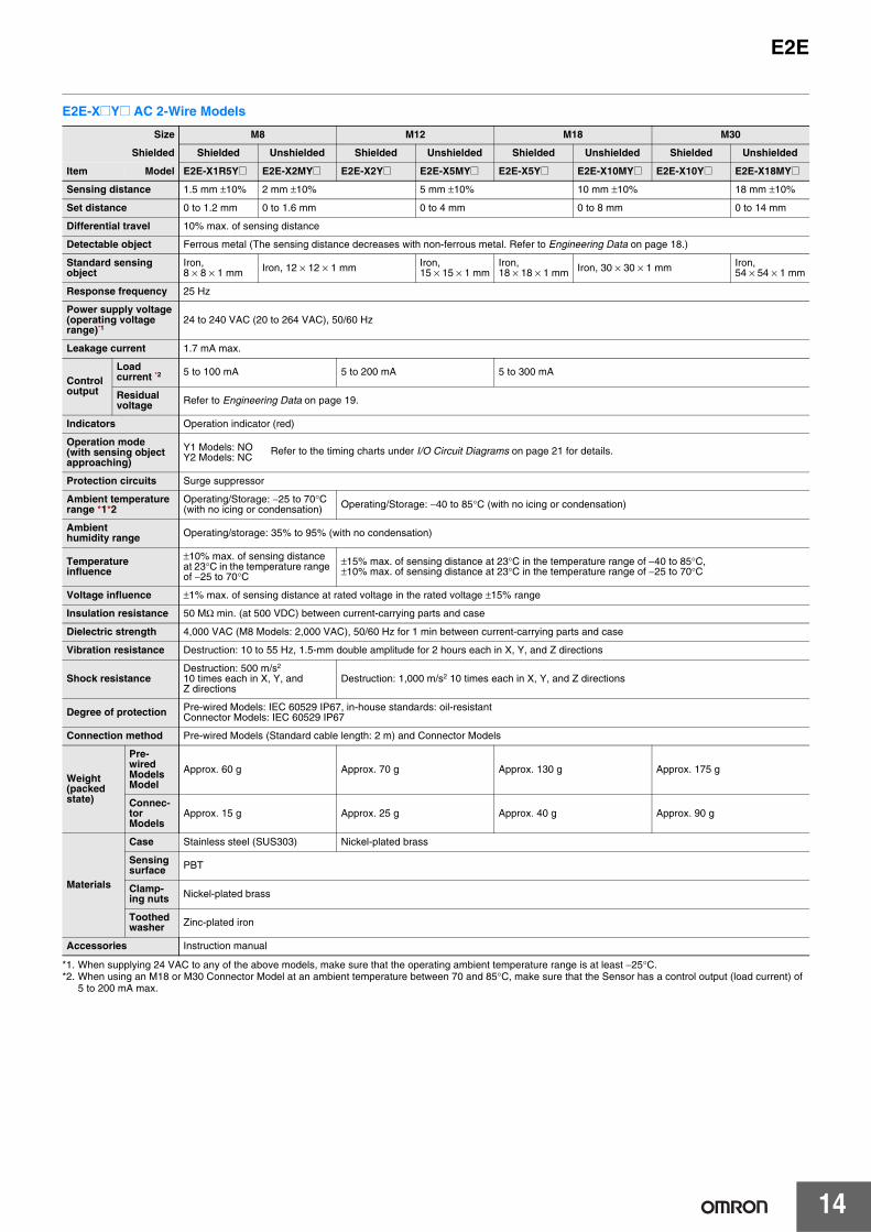
E2E-X@Y@ AC 2-Wire Models
*1. When supplying 24 VAC to any of the above models, make sure that the operating ambient temperature range is at least −25°C. *2. When using an M18 or M30 Connector Model at an ambient temperature between 70 and 85°C, make sure that the Sensor has a control output (load current) of
5 to 200 mA max.
Size M8 M12 M18 M30
Shielded Shielded Unshielded Shielded Unshielded Shielded Unshielded Shielded Unshielded
Item Model E2E-X1R5Y@ E2E-X2MY@ E2E-X2Y@ E2E-X5MY@ E2E-X5Y@ E2E-X10MY@ E2E-X10Y@ E2E-X18MY@
Sensing distance 1.5 mm ±10% 2 mm ±10% 5 mm ±10% 10 mm ±10% 18 mm ±10%
Set distance 0 to 1.2 mm 0 to 1.6 mm 0 to 4 mm 0 to 8 mm 0 to 14 mm
Differential travel 10% max. of sensing distance
Detectable object Ferrous metal (The sensing distance decreases with non-ferrous metal. Refer to Engineering Data on page 18.)
Standard sensing object
Iron, 8 × 8 × 1 mm Iron, 12 × 12 × 1 mm Iron,
15 × 15 × 1 mmIron, 18 × 18 × 1 mm Iron, 30 × 30 × 1 mm Iron,
54 × 54 × 1 mm
Response frequency 25 Hz
Power supply voltage (operating voltage range)*1
24 to 240 VAC (20 to 264 VAC), 50/60 Hz
Leakage current 1.7 mA max.
Control output
Load current *2 5 to 100 mA 5 to 200 mA 5 to 300 mA
Residual voltage Refer to Engineering Data on page 19.
Indicators Operation indicator (red)
Operation mode (with sensing object approaching)
Y1 Models: NOY2 Models: NC
Protection circuits Surge suppressor
Ambient temperature range *1*2
Operating/Storage: −25 to 70°C (with no icing or condensation) Operating/Storage: −40 to 85°C (with no icing or condensation)
Ambient humidity range Operating/storage: 35% to 95% (with no condensation)
Temperature influence
±10% max. of sensing distance at 23°C in the temperature range of −25 to 70°C
±15% max. of sensing distance at 23°C in the temperature range of −40 to 85°C, ±10% max. of sensing distance at 23°C in the temperature range of −25 to 70°C
Voltage influence ±1% max. of sensing distance at rated voltage in the rated voltage ±15% range
Insulation resistance 50 MΩ min. (at 500 VDC) between current-carrying parts and case
Dielectric strength 4,000 VAC (M8 Models: 2,000 VAC), 50/60 Hz for 1 min between current-carrying parts and case
Vibration resistance Destruction: 10 to 55 Hz, 1.5-mm double amplitude for 2 hours each in X, Y, and Z directions
Shock resistanceDestruction: 500 m/s2
10 times each in X, Y, and Z directions
Destruction: 1,000 m/s2 10 times each in X, Y, and Z directions
Degree of protection Pre-wired Models: IEC 60529 IP67, in-house standards: oil-resistantConnector Models: IEC 60529 IP67
Connection method Pre-wired Models (Standard cable length: 2 m) and Connector Models
Weight(packed state)
Pre-wired ModelsModel
Approx. 60 g Approx. 70 g Approx. 130 g Approx. 175 g
Connec-tor Models
Approx. 15 g Approx. 25 g Approx. 40 g Approx. 90 g
Materials
Case Stainless steel (SUS303) Nickel-plated brass
Sensing surface PBT
Clamp-ing nuts Nickel-plated brass
Toothed washer Zinc-plated iron
Accessories Instruction manual
Refer to the timing charts under I/O Circuit Diagrams on page 21 for details.

15
E2E
E2E-X@T1 AC/DC 2-Wire Models
*1. The response frequency is an average value. Measurement conditions are as follows: standard sensing object, a distance of twice the standard sensing object, and a set distance of half the sensing distance.
*2. Power Supply Voltage Waveform:Use a sine wave for the power supply. Using a rectangular AC power supply may result in faulty reset.
Size M12 M18 M30
Shielded Shielded
Item Model E2E-X3T1 E2E-X7T1 E2E-X10T1
Sensing distance 3 mm ±10% 7 mm ±10% 10 mm ±10%
Set distance 0 to 2.4 mm 0 to 5.6 mm 0 to 8 mm
Differential travel 10% max. of sensing distance
Detectable object Ferrous metal (The sensing distance decreases with non-ferrous metal. Refer to Engineering Data on page 17.)
Standard sensing object Iron, 12 × 12 × 1 mm Iron, 18 × 18 × 1 mm Iron, 30 × 30 × 1 mm
Response frequency *1
DC 1 kHz 0.5 kHz 0.4 kHz
AC 25 Hz
Power supply voltage (operating voltage range) *2
24 to 240 VDC (20 to 264 VDC)48 to 240 VAC (40 to 264 VAC)
Leakage current DC: 1 mA max. AC: 2 mA max.
Control output
Load current 5 to 100 mA
Residual voltage
DC: 6 V max. (Load current: 100 mA, Cable length: 2 m)AC: 10 V max. (Load current: 5 mA, Cable length: 2 m)
Indicators Operation indicator (red), Setting indicator (green)
Operation mode (with sensing object approaching)
NO (Refer to the timing charts under I/O Circuit Diagrams on page 21 for details.)
Protection circuits Load short-circuit protection (20 to 40 VDC only), Surge suppressor
Ambient temperature range Operating: −25 to 70°C, Storage: −40 to 85°C (with no icing or condensation)
Ambient humidity range Operating/Storage: 35% to 95% (with no condensation)
Temperature influence ±10% max. of sensing distance at 23°C in the temperature range of −25 to 70°C
Voltage influence ±1% max. of sensing distance at rated voltage in the rated voltage ±15% range
Insulation resistance 50 MΩ min. (at 500 VDC) between current-carrying parts and case
Dielectric strength 4,000 VAC, 50/60 Hz for 1 minute between current-carrying parts and case
Vibration resistance Destruction: 10 to 55 Hz, 1.5-mm double amplitude for 2 hours each in X, Y, and Z directions
Shock resistance Destruction: 1,000 m/s2 10 times each in X, Y, and Z directions
Degree of protection IEC 60529 IP67, in-house standards: oil-resistant
Connection method Pre-wired Models (Standard cable length: 2 m)
Weight (packed state) Approx. 80 g Approx. 140 g Approx. 190 g
Materials
Case Nickel-plated brass
Sensing surface PBT
Clamping nuts Nickel-plated brass
Toothed washer Zinc-plated iron
Accessories Instruction manual

E2E
16
E2E-X@E@/F@ DC 3-Wire Models
*1. The response frequency is an average value. Measurement conditions are as follows: standard sensing object, a distance of twice the standard sensing object, and a set distance of half the sensing distance.
*2. When using an M8 Model at an ambient temperature between 70 and 85°C, supply 10 to 30 VDC to the Sensor and make sure that the Sensor has a control output of 100 mA maximum.
*3. For the information on UL-certified connector models, refer to your OMRON website.
Size M8 M12 M18 M30
Shielded Shielded Unshielded Shielded Unshielded Shielded Unshielded Shielded Unshielded
Item Model E2E-X1R5E@/F@
E2E-X2ME@/F@
E2E-X2E@/F@
E2E-X5ME@/F@
E2E-X5E@/F@
E2E-X10ME@/F@
E2E-X10E@/F@
E2E-X18ME@/F@
Sensing distance 1.5 mm ±10% 2 mm ±10% 5 mm ±10% 10 mm ±10% 18 mm ±10%
Set distance 0 to 1.2 mm 0 to 1.6 mm 0 to 4 mm 0 to 8 mm 0 to 14 mm
Differential travel 10% max. of sensing distance
Detectable object Ferrous metal (The sensing distance decreases with non-ferrous metal. Refer to Engineering Data on page 18.)
Standard sensing object
Iron, 8 × 8 × 1 mm Iron, 12 × 12 × 1 mm Iron,
15 ×15 × 1 mmIron, 18 × 18 × 1 mm Iron, 30 × 30 × 1 mm Iron,
54 × 54 × 1 mm
Response frequency *1 2 kHz 0.8 kHz 1.5 kHz 0.4 kHz 0.6 kHz 0.2 kHz 0.4 kHz 0.1 kHz
Power supply voltage (operating voltage range) *2
12 to 24 VDC, ripple(p-p): 10% max. (10 to 30 VDC) Connector Models Used as UL-certified Models: 12 to 24 VDC, ripple (p-p): 10% max. (The operating voltage range is also the same.) *3
Current consumption 13 mA max.
Control output
Load current *2 200 mA max.
Residual voltage 2 V max. (Load current: 200 mA, Cable length: 2 m)
Indicators Operation indicator (red)
Operation mode (with sensing object approaching)
E1/F1 Models: NOE2/F2 Models: NCRefer to the timing charts under /O Circuit Diagrams on page 21 for details.
Protection circuits Load short-circuit protection, Surge suppressor, Reverse polarity protection
Ambient temperature range *2 Operating/Storage: −40 to 85°C (with no icing or condensation)
Ambient humidity range Operating/Storage: 35% to 95% (with no condensation)
Temperature influence
±15% max. of sensing distance at 23°C in the temperature range of −40 to 85°C±10% max. of sensing distance at 23°C in the temperature range of −25 to 70°C
Voltage influence ±1% max. of sensing distance at rated voltage in the rated voltage ±15% range
Insulation resistance 50 MΩ min. (at 500 VDC) between current-carrying parts and case
Dielectric strength 1,000 VAC, 50/60 Hz for 1 minute between current carry parts and case
Vibration resistance Destruction: 10 to 55 Hz, 1.5-mm double amplitude for 2 hours each in X, Y, and Z directions
Shock resistanceDestruction: 500 m/s2
10 times each in X, Y, and Z directions
Destruction: 1,000 m/s2 10 times each in X, Y, and Z directions
Degree of protection Pre-wired Models : IEC 60529 IP67, in-house standards: oil-resistantConnector Models : IEC 60529 IP67
Connection method Pre-wired Models (Standard cable length: 2 m) and Connector Models
Weight(packed state)
Pre-wired Models
Approx. 65 g Approx. 75 g Approx. 150 g Approx. 195 g
Connec-tor Models
Approx. 15 g Approx. 25 g Approx. 40 g Approx. 90 g
Materials
Case Stainless steel (SUS303) Nickel-plated brass
Sensing surface PBT
Clamp-ing nuts Nickel-plated brass
Toothed washer Zinc-plated iron
Accessories Instruction manual

17
E2E
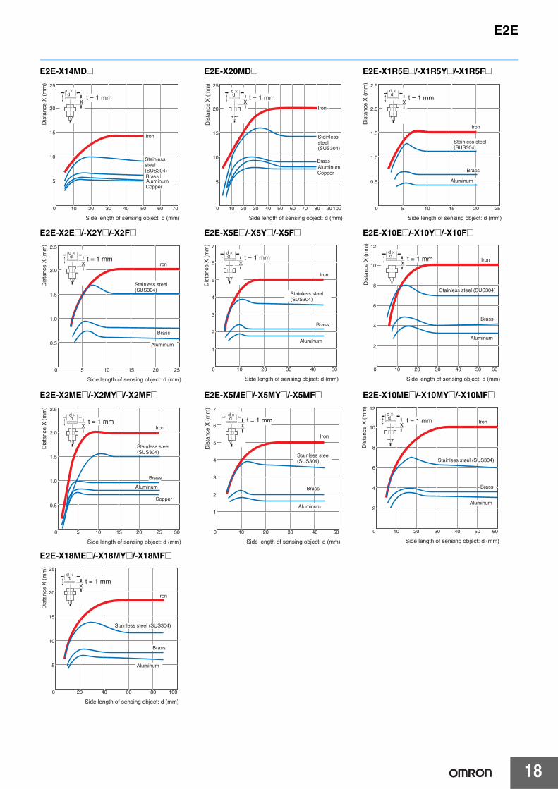
Engineering Data (Reference Value)
Sensing Area
Shielded Models
E2E-X@D@/-X@T1 E2E-X@E@/-X@Y@/-X@F@
Unshielded Models
E2E-X@MD@ E2E-X@ME@/-X@MY@/-X@MF@
Influence of Sensing Object Size and Material
E2E-X2D@ E2E-X3D@/-X3T1 E2E-X7D@/-X7T1
E2E-X10D@/-X10T1 E2E-X4MD@ E2E-X8MD@
XY
E2E-X10
E2E-X7
E2E-X3
E2E-X2
−20 −15 −10 −5 0 5 10 15
12
10
8
6
4
2
0
Distance Y (mm)
Dis
tanc
e X
(m
m)
E2E-X10
E2E-X1R5
E2E-X5
E2E-X2
XY
−15 −10 −5 0 5 10
12
10
8
6
4
2
0
Distance Y (mm)
Dis
tanc
e X
(m
m)
XY
E2E-X20M
E2E-X14M
E2E-X8M
E2E-X4M
−30 −20 −10 0 10 20
30
25
20
15
10
5
0
Distance Y (mm)
Dis
tanc
e X
(m
m)
E2E-X18M
E2E-X10M
E2E-X5M
E2E-X2M
XY
−30 −20 −10 0 10 20
30
25
20
15
10
5
0
Distance Y (mm)
Dis
tanc
e X
(m
m)
0 5 10 15 20 25
3.0
2.5
2.0
1.5
1.0
0.5
X
d × d t = 1 mm
Side length of sensing object: d (mm)
Iron
Stainless steel (SUS304)
Brass
AluminumCopper
Dis
tanc
e X
(m
m)
0 5 10 15 20 25 30 35 40
4.0
3.5
3.0
2.5
2.0
1.5
1.0
0.5
X
d × d t = 1 mm
Side length of sensing object: d (mm)
Iron
Stainless steel (SUS304)
Brass
AluminumCopper
Dis
tanc
e X
(m
m)
0 10 20 30 40 50
8
7
6
5
4
3
2
1
X
d × d t = 1 mm
Side length of sensing object: d (mm)
Iron
Stainless steel (SUS304)
Brass
Aluminum
Copper
Dis
tanc
e X
(m
m)
0 10 20 30 40 50 60 70
12
10
8
6
4
2
X
d × d
t = 1 mm
Side length of sensing object: d (mm)
Iron
Stainless steel (SUS304)
BrassAluminumCopper
Dis
tanc
e X
(m
m)
0 10 20 30 40 50 60 70
6
5
4
3
2
1
X
d × d t = 1 mm
Brass
Copper
Side length of sensing object: d (mm)
Iron
Stainless steel (SUS304)
Aluminum
Dis
tanc
e X
(m
m)
0 10 15 20 30 40 50 60 70
12
10
8
6
4
2
X
d × d t = 1 mm
Side length of sensing object: d (mm)
Iron
Stainless steel (SUS304)
Brass
AluminumCopper
Dis
tanc
e X
(m
m)
E2E
18
E2E-X14MD@ E2E-X20MD@ E2E-X1R5E@/-X1R5Y@/-X1R5F@
E2E-X2E@/-X2Y@/-X2F@ E2E-X5E@/-X5Y@/-X5F@ E2E-X10E@/-X10Y@/-X10F@
E2E-X2ME@/-X2MY@/-X2MF@ E2E-X5ME@/-X5MY@/-X5MF@ E2E-X10ME@/-X10MY@/-X10MF@
E2E-X18ME@/-X18MY@/-X18MF@
0 10 20 30 40 50 60 70
25
20
15
10
5
X
d × d
t = 1 mm
Side length of sensing object: d (mm)
Iron
Stainless steel (SUS304)BrassAluminumCopper
Dis
tanc
e X
(m
m)
0 10 20 30 40 50 60 70 80 90 100
25
20
15
10
5
X
d × d t = 1 mm
Side length of sensing object: d (mm)
Iron
Stainless steel (SUS304)
BrassAluminumCopper
Dis
tanc
e X
(m
m)
0 5 10 15 20 25
2.5
2.0
1.5
1.0
0.5
X
d × d
t = 1 mm
Side length of sensing object: d (mm)
Iron
Stainless steel (SUS304)
Brass
Aluminum
Dis
tanc
e X
(m
m)
0 5 10 15 20 25
2.5
2.0
1.5
1.0
0.5
X
d × d t = 1 mm
Side length of sensing object: d (mm)
Iron
Stainless steel (SUS304)
Brass
Aluminum
Dis
tanc
e X
(m
m)
0 10 20 30 40 50
7
6
5
4
3
2
1
X
d × d t = 1 mm
Side length of sensing object: d (mm)
Stainless steel (SUS304)
Iron
Brass
Aluminum
Dis
tanc
e X
(m
m)
0 10 20 30 40 50 60
12
10
8
6
4
2
X
d × d t = 1 mm
Side length of sensing object: d (mm)
Stainless steel (SUS304)
Iron
Brass
Aluminum
Dis
tanc
e X
(m
m)
0 5 10 15 20 25 30
2.5
2.0
1.5
1.0
0.5
X
d × d t = 1 mm
Side length of sensing object: d (mm)
Iron
Stainless steel (SUS304)
Brass
Aluminum
Copper
Dis
tanc
e X
(m
m)
0 10 20 30 40 50
7
6
5
4
3
2
1
X
d × d t = 1 mm
Side length of sensing object: d (mm)
Stainless steel (SUS304)
Iron
Brass
Aluminum
Dis
tanc
e X
(m
m)
0 10 20 30 40 50 60
12
10
8
6
4
2
X
Side length of sensing object: d (mm)
Stainless steel (SUS304)
Iron
Brass
Aluminum
d × d t = 1 mm
Dis
tanc
e X
(m
m)
0 20 40 60 80 100
25
20
15
10
5
X
d × d t = 1 mm
Side length of sensing object: d (mm)
Stainless steel (SUS304)
Iron
Brass
Aluminum
Dis
tanc
e X
(m
m)

E2E
19
Leakage Current
E2E-X@D@ E2E-X@Y@ E2E-X@T1
Residual Output Voltage
E2E-X@D@ E2E-X@T1
E2E-X@Y@ at 24 VAC E2E-X@Y@ at 100 VAC E2E-X@Y@ at 200 VAC
0 5 10 15 20 25 30
1.0
0.8
0.6
0.4
0.2
E2E-X2D1-N
E2E-X7D1-N
E2E-X3D1-N
E2E-X10D1-N
Power supply voltage (V)
Leak
age
curr
ent (
mA
)
V
0 50 100 150 200 250 300
1.4
1.2
1.0
0.8
0.6
0.4
0.2
~mA
~
Power supply voltage (V)
AC power
Protective resistance
Proximity Sensor (OFF)
Leak
age
curr
ent (
mA
)
0 50 100 150 200 250 300
1.4
1.2
1.0
0.8
0.6
0.4
0.2
Power supply voltage (V)
AC power
DC power
Leak
age
curr
ent (
mA
)
5
4
3
2
1
01 3 5 10 30 50 100
E2E-X@D@
E2E-X@D1-M1J-T
Load current (mA)
Res
idua
l out
put v
olta
ge (
V) 6
5
4
3
2
1 3 5 10 30 50 100
24 VDC
100 VAC
200 VAC
Load current (mA)
Res
idua
l out
put v
olta
ge (
V)
V
30
25
20
15
10
5
01 3 5 10 30 50 100 300 500
VL
~
~A24 VAC
OFF
ONLoad
vol
tage
VL
(V)
Load current (mA)
Residual load voltage
Residual output voltageV
120
100
80
60
40
20
01 3 5 10 30 50 100 300 500
100 VACVL
~
~A
OFF
ON
Load current (mA)
Residual output voltage
Residual load voltage
Load
vol
tage
VL
(V)
V
200 VACVL
~A
240
200
160
120
80
40
0
~
ON
1 3 5 10 30 50 100 300 500
OFF
Load current (mA)
Residual output voltage
Residual load voltage
Load
vol
tage
VL
(V)

E2E
20
I/O Circuit Diagrams
E2E-X@D@ DC 2-Wire ModelsOperation
mode Model Timing Chart Output circuit
Without self-
diagnostic output:
NO
E2E-X@D1-NE2E-X@D1-M1G(J)E2E-X@D1(-M1TGJ)-UE2E-X@D1-M3GE2E-X@D1(-M1TGJ)-US
E2E-X@D1-M1J-T
Without self-
diagnostic output:
NC
E2E-X@D2-NE2E-X@D2-M1GE2E-X@D2(-M1TGJ)-UE2E-X@D2-M3GE2E-X@D2(-M1TGJ)-US
With self-diagnostic
output: NO
E2E-X@D1SE2E-X@D1S-M1
(%) 80 0100
Sensing object
Rated sensing distance
Stable sensing areaNon-sensing
area
Unstable sensing area
Set position
Proximity Sensor
ON
OFF
ON
OFF
ON
OFF
Setting indicator (green)
Operation indicator (red)
Control output
0 V
+V
4
1Load
Brown
Blue
Polarity: Yes
Note: The load can be connected to either the +V or 0 V side.
Prox-imitySensormaincircuit
0 V(+V)
+V(0 V)
3
4Load
Prox-imitySensormaincircuit
Polarity: None
Note 1. The load can be connected to either the +V or 0 V side.
2. The E2E-X@D1-M1J-T has no polarity. Therefore, terminals 3 and 4 have no polarity.
0(%) 100
Sensing object
Rated sensing distance
Sensing areaNon-sensing
area
Proximity Sensor
ON
OFF
ON
OFF
Operation indicator (red)
Control output
0 V
+V
2
1Load
Brown
Blue
Note: The load can be connected to either the +V or 0 V side.
Prox-imitySensormaincircuit
(%) 80 0100
Sensing object
Rated sensing distance
Stable sensing areaNon-sensing
area
Unstable sensing area
Set position
Proximity Sensor
ON
OFF
ON
OFF
ON
OFF
ON
OFF
Setting indicator (green)
Operation indicator (red)
Control output
Diagnostic output*
* The diagnostic output is ON when there is a coil burnout or the sensing object is located in the unstable sensing area for 0.3 s or longer.
+V
+V
0
Load
Load
Brown (4)
Orange (2)(diagnosticoutput)
Blue (3)
Note: Connect both the loads to the +V side of the control output and diagnostic output.
Prox-imitySensormaincircuit

21
E2E
DC 3-Wire Models
AC 2-Wire Models
AC/DC 2-Wire Models
Operation mode
Output specifica-
tionsModel Timing Chart Output circuit
NO
NPN outputE2E-X@E@E2E-X@E@-M1E2E-X@E@-M3
NC
NO
PNP outputE2E-X@F@E2E-X@F@-M1E2E-X@F@-M3
NC
Operation mode Model Timing Chart Output circuit
NO
E2E-X@Y@E2E-X@Y@-M1
NC
Operation mode Model Timing Chart Output circuit
NO E2E-X@T1
Present
Not present
ON
OFF
ON
OFF
High
Low
Operation indicator (red)
Sensing object
Control output (between brown and black leads)
Output voltage (between black and blue leads)
+V
Tr
0 V
100 Ω
3
4
1
Load
Brown
Black
*Constant current output is 1.5 to 3 mA.Blue
Constantcurrent*
ProximitySensor
maincircuit
Note: For Connector Models, the connection between pins 1, 4 and 3 uses an NO contact, and the connection between pins 1, 2 and 3 uses an NC contact.
2
Present
Not present
ON
OFF
ON
OFF
High
Low
Operation indicator (red)
Sensing object
Control output (between brown and black leads)
Output voltage (between black and blue leads)
Present
Not present
ON
OFF
ON
OFF
High
Low
Operation indicator (red)
Sensing object
Control output (Between blue and black leads)
Output voltage (between brown and black leads)
100 Ω
Tr
+V
*
Load
Brown
Black
*When a transistor is connected
Blue
ProximitySensor
maincircuit
Note: For Connector Models, the connection between pins 1, 4 and 3 uses an NO contact, and the connection between pins 1, 2 and 3 uses an NC contact.
0 V
3
4
1
2
Present
Not present
ON
OFF
ON
OFF
High
Low
Operation indicator (red)
Sensing object
Control output (Between blue and black leads)
Output voltage (between brown and black leads)
Present
Not present
ON
OFF
Operate
Reset
Operation indicator (red)
Sensing object
Control output
Load
Brown 3 (or 1)
Blue 4 (or 2)
ProximitySensor
maincircuit
Note: For Connector Models, the connection between pins 3 and 4 uses an NO contact, and the connection between pins 1 and 2 uses an NC contact.
Present
Not present
ON
OFF
Operate
Reset
Operation indicator (red)
Sensing object
Control output
80100 0(%)
Sensing object
Rated sensing distance
Stable sensing areaNon-sensing
area
Unstable sensing area
Set position
Proximity Sensor
ON
OFF
ON
OFF
ON
OFF
Setting indicator (green)
Operation indicator (red)
Control output
24 to 240 VDC
48 to 240 VAC
LoadBrown
Blue
ProximitySensor
maincircuit
Powersupply
Note: The load can be connected to either the +V or 0 V side. There is no need to be concerned about the polarity (brown/blue) of the Proximity Sensor.

E2E
22
Sensor I/O Connectors (Sockets on One Cable End)Model for Connectors and Pre-wired Connectors: A Connector is not provided with the Sensor. Be sure to order a Connector separately. [Refer to Dimensions for the XS2, XS3, and XS5.]
Note: Refer to Introduction to Sensor I/O Connectors/Sensor Controllers for details and for information on Cable length and Robotics Cables. *1. Images of straight and L-shaped connectors.
*2. Refer to Connection Diagrams on page 23 for information on Proximity Sensor and I/O Connector connections.
Applicable connector
code
ConnectorApplicable Proximity
Sensor model number
Connection diagram No. *2Screw Appearance *1
Cable length 2m Cable length 5mCablConnector model number
CablConnector model number
A
M12
Straight XS2F-D421-DA0-F XS2F-D421-GA0-FE2E-X@D1-M1G(J) 1
L-shape XS2F-D422-DA0-F XS2F-D422-GA0-F
BStraight XS2F-D421-DC0-F XS2F-D421-GC0-F E2E-X@E1-M1
E2E-X@F1-M1 10L-shape XS2F-D422-DC0-F XS2F-D422-GC0-F
CStraight XS2F-D421-DD0 XS2F-D421-GD0
E2E-X@D1-M1J-T 3E2E-X@D1-M1 2
L-shape XS2F-D422-DD0 XS2F-D422-GD0E2E-X@D1-M1J-T 3E2E-X@D1-M1 2
D
Straight XS2F-D421-D80-F XS2F-D421-G80-F
E2E-X@D2-M1G(J) 6E2E-X@D2-M1J-T 8E2E-X@D2-M1 7E2E-X@D1S-M1 5E2E-X@E2-M1E2E-X@F2-M1 11
L-shape XS2F-D422-D80-F XS2F-D422-G80-F
E2E-X@D2-M1G(J) 6E2E-X@D2-M1J-T 8E2E-X@D2-M1 7E2E-X@D1S-M1 5E2E-X@E2-M1E2E-X@F2-M1 11
EStraight XS2F-A421-DB0-F XS2F-A421-GB0-F
E2E-X@Y1-M1 14L-shape XS2F-A422-DB0-F XS2F-A422-GB0-F
F Straight XS2F-A421-D90-F XS2F-A421-G90-F E2E-X@Y2-M1 15
G Smartclick Connector,Straight XS5F-D421-D80-F XS5F-D421-G80-F
E2E-X@D1-M1TGJ(-US) 16E2E-X@D2-M1TGJ-US 17
H
Smartclick Connector,Straight
Oil-resistant Reinforced Cables
XS5F-D421-D80-P XS5F-D421-G80-P
E2E-X@D1-M1TGJ-U 18
E2E-X@D2-M1TGJ-U 19
I M8
Straight XS3F-M421-402-A XS3F-M421-405-A
E2E-X@D1-M3G 4E2E-X@D2-M3G 9E2E-X@E1-M3E2E-X@F1-M3 12
E2E-X@E2-M3E2E-X@F2-M3 13
L-shape XS3F-M422-402-A XS3F-M422-405-A
E2E-X@D1-M3G 4E2E-X@D2-M3G 9E2E-X@E1-M3E2E-X@F1-M3 12
E2E-X@E2-M3E2E-X@F2-M3 13
M12 Straight M12 L-shape M8 Straight M8 L-shape

23
E2E
Connections for Sensor I/O Connectors
* Different from Proximity Sensor wire colors.
Connection diagram No.
Proximity SensorSensor I/O Connector
model number ConnectionsType Operation
mode Model
1 DC 2-wire (IEC pin wiring)
NO
E2E-X@D1-M1G/M1GJ
2DC 2-wire (previous pin wiring)
E2E-X@D1-M1
3 DC 2-wire (no polarity) E2E-X@D1-M1J-T
4 DC 2-wire (M8 connector) E2E-X@D1-M3G
5DC 2-wire (diagnostic type)
E2E-X@D1S-M1
6 DC 2-wire (IEC pin wiring)
NC
E2E-X@D2-M1G/M1GJ
7DC 2-wire (previous pin wiring)
E2E-X@D2-M1
8 DC 2-wire (no polarity) E2E-X@D2-M1J-T
9 DC 2-wire (M8 connector) E2E-X@D2-M3G
XS2F-D42@-@A0-F
1: Straight2: L-shape
D: 2-m cableG: 5-m cable
4
3
2
1
4
3
2
1
XS2FE2E
Mai
n ci
rcui
t Brown (+)
Blue (−)
XS2F-D42@-@D0
1: Straight2: L-shape
D: 2-m cableG: 5-m cable
2
4
3
2
1
4
3
1
XS2FE2E
Blue (−)Brown (+)
Mai
n ci
rcui
t
XS2F-D42@-@D0
1: Straight2: L-shape
D: 2-m cableG: 5-m cable
4321
4321
E2E
Mai
nci
rcui
t
XS2F
Blue (+) (−)Brown (−) (+)
XS3F-M42@-40@-A
1: Straight2: L-shape
2: 2-m cable5: 5-m cable
*XS3F
4
3
2
1
4
3
2
1
E2E
Brown (+)White (not connected) Blue (not connected)
Black (−)
Mai
n ci
rcui
t
XS2F-D42@-@80-F
1: Straight2: L-shape
D: 2-m cableG: 5-m cable
*XS2F
4
3
2
1
4
3
2
1
E2E
Brown (not connected) White (diagnostic output) (+)Blue (0 V)Black (control output) (+)
Mai
n ci
rcui
t
XS2F-D42@-@80-F
1: Straight2: L-shape
D: 2-m cableG: 5-m cable
*XS2F
4
3
2
1
4
3
2
1
E2E
White (−)Blue (not connected)
Brown (+)
Black (not connected)
Mai
n ci
rcui
t
XS2F-D42@-@80-F
1: Straight2: L-shape
D: 2-m cableG: 5-m cable
*XS2F
4
3
2
1
4
3
2
1
E2E
White (+)Blue (−)
Brown (not connected)
Black (not connected)
Mai
n ci
rcui
t
XS2F-D42@-@80-F
1: Straight2: L-shape
D: 2-m cableG: 5-m cable
*XS2F
4321
4321
E2E
Mai
nci
rcui
t
White (−)(+)Blue (not connected)
Brown (+)(−)
Black (not connected)
XS3F-M42@-40@-A
1: Straight2: L-shape
2: 2-m cable5: 5-m cable
*XS3F
4
3
2
1
4
3
2
1
E2E
White (−)Blue (not connected)
Brown (+)
Black (not connected)
Mai
n ci
rcui
t

E2E
24
* Different from Proximity Sensor wire colors.
Connection diagram No.
Proximity SensorSensor I/O Connector
model number ConnectionsType Operation
mode Model
10
DC 3-wire
NO E2E-X@E/F1-M1
11 NC E2E-X@E2/F2-M1
12
DC 3-wire (M8 connector)
NO E2E-X@E1/F1-M3
13 NC E2E-X@E2/F2-M3
14
AC 2-wire
NO E2E-X@Y1-M1
15 NC E2E-X@Y2-M1
16
DC 2-wire(Smartclick connector)
NO E2E-X@D1-M1TGJ(-US)
17 NC E2E-X@D2-M1TGJ-US
18 NO E2E-X@D1-M1TGJ-U
19 NC E2E-X@D2-M1TGJ-U
Refer to Introduction to Sensor I/O Connectors/Sensor Controllers for details.
XS2F-D42@-@C0-F
1: Straight2: L-shape
D: 2-m cableG: 5-m cable
XS2F
4
3
2
1
4
3
2
1
E2E
Brown (+V)
Blue (0 V)Black (output)
Mai
n ci
rcui
t
XS2F-D42@-@80-F
1: Straight2: L-shape
D: 2-m cableG: 5-m cable
XS2F
4
3
2
1
4
3
2
1
E2E
Brown (+V)White (output) Blue (0 V)Black (not connected)
Mai
n ci
rcui
t
XS3F-M42@-40@-A
1: Straight2: L-shape
2: 2-m cable5: 5-m cable
XS3F
4
3
2
1
4
3
2
1
E2E
Brown (+V)White (not connected) Blue (0 V)Black (output)
Mai
n ci
rcui
t
XS3F-M42@-40@-A
1: Straight2: L-shape
2: 2-m cable5: 5-m cable
XS3F
4
3
2
1
4
3
2
1
E2E
Brown (+V)White (output) Blue (0 V)Black (not connected)
Mai
n ci
rcui
t
XS2F-A42@-@B0-F
1: Straight2: L-shape
D: 2-m cableG: 5-m cable
XS2F
4
3
2
1
4
3
2
1
E2E
BrownBlue
Mai
n ci
rcui
t
XS2F-A421-@90-F
D: 2-m cableG: 5-m cable
*XS2F
4
3
2
1
4
3
2
1
E2E
Blue (not connected) Black (not connected)
BrownWhite
Mai
n ci
rcui
t
XS5F-D421-@80-F
D: 2-m cableG: 5-m cable
XS5F
4
3
2
1
4
3
2
1
E2E
Blue (not connected) Black (−)
Brown (+)White (not connected)
Mai
n ci
rcui
t
XS5F-D421-@80-F
D: 2-m cableG: 5-m cable
XS5F
4321
4321
E2E
Blue (not connected) Black (not connected)
Brown (+)White (−)
Mai
n ci
rcui
t
XS5F-D421-@80-P
D: 2-m cableG: 5-m cable
XS5F
4
3
2
1
4
3
2
1
E2E
Blue (not connected) Black (−)
Brown (+)White (not connected)
Mai
n ci
rcui
t
XS5F-D421-@80-P
D: 2-m cableG: 5-m cable
XS5F
4321
4321
E2E
Blue (not connected) Black (not connected)
Brown (+)White (−)
Mai
n ci
rcui
t

25
E2E
Safety Precautions
Refer to Warranty and Limitations of Liability.
This product is not designed or rated for ensuring safety of persons either directly or indirectly.Do not use it for such purposes.
Do not use this product under ambient conditions that exceed the ratings.
● DesignInfluence of Surrounding MetalWhen mounting the Sensor within a metal panel, ensure that the clearances given in the following table are maintained. Failure to maintain these distances may cause deterioration in the performance of the Sensor.
WARNING
CAUTION• Do not short the load. Explosion or burning may
result. • Do not supply power to the Sensor with no load,
otherwise Sensor may be damaged.
Precautions for Correct Use
l
mn
mD
d dia.
l
Influence of Surrounding Metal (Unit: mm)
Model Item M8 M12 M18 M30
DC 2-Wire ModelsE2E-X@D@
AC/DC 2-Wire ModelsE2E-X@T1
Shielded
l 0d 8 12 18 30D 0m 4.5 8 20 40n 12 18 27 45
Unshielded
l 12 15 22 30d 24 40 70 90D 12 15 22 30m 8 20 40 70n 24 40 70 90
DC 3-Wire ModelsE2E-X@E@E2E-X@F@
AC 2-Wire ModelsE2E-X@Y@
Shielded
l 0d 8 12 18 30D 0m 4.5 8 20 40n 12 18 27 45
Unshielded
l 6 15 22 30d 24 40 55 90D 6 15 22 30m 8 20 40 70n 24 36 54 90
Relationship between Sizes and Models
Model Model
M8
Shielded
E2E-X2D@E2E-X1R5E@E2E-X1R5F@E2E-X1R5Y@
Unshielded
E2E-X4MD@E2E-X2ME@E2E-X2MF@E2E-X2MY@
M12
Shielded
E2E-X3D@E2E-X2E@E2E-X2F@E2E-X2Y@E2E-X3T1
Unshielded
E2E-X8MD@E2E-X5ME@E2E-X5MF@E2E-X5MY@
M18
Shielded
E2E-X7D@E2E-X5E@E2E-X5F@E2E-X5Y@E2E-X7T1
Unshielded
E2E-X14MD@E2E-X10ME@E2E-X10MF@E2E-X10MY@
M30
Shielded
E2E-X10D@E2E-X10E@E2E-X10F@E2E-X10Y@E2E-X10T1
Unshielded
E2E-X20MD@E2E-X18ME@E2E-X18MF@E2E-X18MY@

E2E
26
Loads with Large Surge Currents (E2E-X@T@)If a load with a large surge current is connected, such as a relay, lamp, or motor, the surge current may cause the load short-circuit protection circuit to operate, resulting in operating errors.
● MountingTightening ForceDo not tighten the nut with excessive force. A washer must be used with the nut.
Note: 1. The allowable tightening strength depends on the distance from the edge of the head, as shown in the following table. (A is the distance from the edge of the head. B includes the nut on the head side. If the edge of the nut is in part A, the tightening torque for part A applies instead.)
2. The following strengths assume washers are being used.
Connecting a DC 2-Wire Proximity Sensor to a PLC (Programmable Controller)Required ConditionsConnection to a PLC is possible if the specifications of the PLC and the Proximity Sensor satisfy the following conditions. (The meanings of the symbols are given at the right.)1. The ON voltage of the PLC and the residual voltage of the Proximity
Sensor must satisfy the following. VON ≤ VCC − VR
2. The OFF current of the PLC and the leakage current of the Proximity Sensor must satisfy the following.
IOFF ≥ Ileak
(If the OFF current is not listed in the PLC’s input specifications, take it to be 1.3 mA.)
3. The ON current of the PLC and the control output of the Proximity Sensor must satisfy the following.
IOUT (min.) ≤ ION ≤ IOUT (max.)The ON current of the PLC will vary, however, with the power supply voltage and the input impedance, as shown in the following equation.
ION = (VCC − VR − VPC) / RIN
ExampleIn this example, the above conditions are checked when the Proximity Sensor is the E2E-X7D1-N and the power supply voltage is 24 V. 1. VON (14.4 V) ≤ VCC (20.4 V) − VR (3 V) = 17.4 V: OK2. IOFF (1.3 mA) ≥ Ileak (0.8 mA): OK3. ION = [VCC (20.4 V) − VR (3 V) − VPC (4 V)] / RIN (3 kΩ)
= Approx. 4.5 mATherefore, IOUT (min.) (3 mA) ≤ ION (4.5 mA): OKConnection is thus possible.
Connection Example (Reference)
Mutual Interference (Unit: mm)
Note: Values in parentheses apply to Sensors operating at different frequencies.* Mutual interference will not occur for close-proximity mounting if models with different frequencies are used together.
Model Item M8 M12 M18 M30
DC 2-Wire ModelsE2E-X@D@
AC/DC 2-Wire ModelsE2E-X@T1
ShieldedA 20 30 (20) 50 (30) 100 (50)
B 15 20 (12) * 35 (18) * 70 (35)
UnshieldedA 80 120 (60) 200 (100) 300 (100)
B 60 100 (50) 110 (60) 200 (100)
DC 3-Wire ModelsE2E-X@E@/X@F@
AC 2-Wire ModelsE2E-X@Y@
ShieldedA 20 30 (20) 50 (30) 100 (50)
B 15 20 (12) * 35 (18) * 70 (35)
UnshieldedA 80 120 (60) 200 (100) 300 (100)
B 60 100 (50) 110 (60) 200 (100)
Mutual InterferenceWhen installing Sensors face-to-face or side-by-side, ensure that the minimum distances given in the following table are maintained.
A
B
ModelPart A Part B
Dimension Torque Torque
M8Shielded 9
9 N·m 12 N·mUnshielded 3
M12 30 N·m
M18 70 N·m
M30 180 N·m
Part B Part A Part B Part A
Shielded Models Unshielded Models
PLC
VON: ON voltage (14.4 V)ION: ON current (typically 7 mA)IOFF: OFF current (1.3 mA)RIN: Input impedance (3 kΩ) VPC: Internal residual voltage (4 V)
Proximity Sensor
VR: Output residual voltage (3 V)Ileak: Leakage current (0.8 mA)IOUT: Control output (3 to 100 mA)VCC: Power supply voltage (PLC: 20.4 to 26.4 V)

27
E2E
Dimensions
Main UnitsModel Number-Dimensions Drawing Number Lookup Table
Note 1. Two clamping nuts and one toothed washer are provided with M8 to M30 Models. 2. The model numbers of M8 to M30 Pre-wired Models are laser-marked on the milled section and cable section. This does not apply, however, to models that
end in -U.
Model DC 2-Wire Models DC 3-Wire Models AC 2-Wire Models AC/DC 2-Wire ModelsModel Shielded Model No. Model No. Model No. Model No.
Pre-wired Models
Shielded
M8 E2E-X2D@(-US) 1 E2E-X1R5E@/F@ 1 E2E-X1R5Y@ 3 ---
M12 E2E-X3D@(-US) 5 E2E-X2E@/F@ 5 E2E-X2Y@ 7 E2E-X3T1 9
M18 E2E-X7D@(-US) 10 E2E-X5E@/F@ 10 E2E-X5Y@ 10 E2E-X7T1 10
M30 E2E-X10D@(-US) 12 E2E-X10E@/F@ 12 E2E-X10Y@ 12 E2E-X10T1 12
Unshielded
M8 E2E-X4MD@(-US) 2 E2E-X2ME@/F@ 2 E2E-X2MY@ 4
---M12 E2E-X8MD@(-US) 6 E2E-X5ME@/F@ 6 E2E-X5MY@ 8
M18 E2E-X14MD@(-US) 11 E2E-X10ME@/F@ 11 E2E-X10MY@ 11
M30 E2E-X20MD@(-US) 13 E2E-X18ME@/F@ 13 E2E-X18MY@ 13
Connector Models(M12)
Shielded
M8 E2E-X2D@-M1(G) 14 E2E-X1R5E/F@-M1 14 ---
---M12 E2E-X3D@-M1(G) 16 E2E-X2E/F@-M1 16 E2E-X2Y@-M1 18
M18 E2E-X7D@-M1(G) 20 E2E-X5E/F@-M1 20 E2E-X5Y@-M1 20
M30 E2E-X10D@-M1(G) 22 E2E-X10E/F@-M1 22 E2E-X10Y@-M1 22
Unshielded
M8 E2E-X4MD@-M1(G) 15 E2E-X2ME/F@-M1 15 ---
---M12 E2E-X8MD@-M1(G) 17 E2E-X5ME/F@-M1 17 E2E-X5MY@-M1 19
M18 E2E-X14MD@-M1(G) 21 E2E-X10ME/F@-M1 21 E2E-X10MY@-M1 21
M30 E2E-X20MD@-M1(G) 23 E2E-X18ME/F@-M1 23 E2E-X18MY@-M1 23
Connector Models(M8)
ShieldedM8
E2E-X2D@-M3G 24 E2E-X1R5E/F@-M3 24--- ---
Unshielded E2E-X4MD@-M3G 25 E2E-X2ME/F@-M3 25
Pre-wired Connector Models
Shielded
M8E2E-X2D@-M1(T)GJ(-U)
26
--- --- ---
E2E-X2D@-M1TGJ-US
M12E2E-X3D@-M1(T)GJ(-U)
27E2E-X3D@-M1TGJ-US
M18E2E-X7D@-M1(T)GJ(-U)
28E2E-X7D@-M1TGJ-US
M30E2E-X10D@-M1(T)GJ(-U)
29E2E-X10D@-M1TGJ-US
Unshielded
M8 E2E-X4MD@-M1TGJ-US 30
--- --- ---
M12E2E-X8MD1-M1(T)GJ
31E2E-X8MD@-M1TGJ-US
M18E2E-X14MD1-M1(T)GJ
32E2E-X14MD@-M1TGJ-US
M30E2E-X20MD1-M1(T)GJ
33E2E-X20MD@-M1TGJ-US
Pre-wired Connector Models(no polarity)
Shielded
M12 E2E-X3D1-M1J-T 27
--- --- ---M18 E2E-X7D@-M1J-T 28
M30 E2E-X10D@-M1J-T 29
(Unit: mm)Tolerance class IT16 applies to dimensions in this data sheet unless otherwise specified.

E2E
28
Pre-wired Models (Shielded) Pre-wired Models (Unshielded)
30 7
826
3
M8 × 1
13
15 dia.
*1Indicators *2
Two clamping nutsToothed washer
*1. 4-dia. vinyl-insulated round cable with 2 conductors (Conductor cross section: 0.3 mm2, Insulator diameter: 1.3 mm), Standard length: 2 m4-dia. vinyl-insulated round cable with 3 conductors (Conductor cross section: 0.3 mm2, Insulator diameter: 1.3 mm), Standard length: 2 mRobotics Cable Models:4-dia. vinyl-insulated round cable with 2 conductors (Conductor cross section: 0.3 mm2, Insulator diameter: 1.27 mm), Standard length: 2 m4-dia. vinyl-insulated round cable with 3 conductors (Conductor cross section: 0.3 mm2, Insulator diameter: 1.27 mm), Standard length: 2 mModels with Highly Oil-resistant Cables:4-dia. polyurethane-insulated round cable with 2 conductors (Conductor cross section: 0.3 mm2, Insulator diameter: 1.3 mm), Standard length: 2 mThe cable can be extended up to 200 m (separate metal conduit).
*2. D1 Models: Operation indicator (red) and setting indicator (green), D2/E/F Models: Operation indicator (red)
Diagram 1 E2E-X2D@E2E-X1R5E@/F@
30 7
8
26
13 6 3
15 dia.
M8 × 1
6.1 dia.*1
Indicators *2Two clamping nuts
Toothed washer
*1. 4-dia. vinyl-insulated round cable with 2 conductors (Conductor cross section: 0.3 mm2, Insulator diameter: 1.3 mm), Standard length: 2 m4-dia. vinyl-insulated round cable with 3 conductors (Conductor cross section: 0.3 mm2, Insulator diameter: 1.3 mm), Standard length: 2 mRobotics Cable Models:4-dia. vinyl-insulated round cable with 2 conductors (Conductor cross section: 0.3 mm2, Insulator diameter: 1.27 mm), Standard length: 2 m4-dia. vinyl-insulated round cable with 3 conductors (Conductor cross section: 0.3 mm2, Insulator diameter: 1.27 mm), Standard length: 2 mThe cable can be extended up to 200 m (separate metal conduit).
*2. D1 Models: Operation indicator (red) and setting indicator (green), D2/E/F Models: Operation indicator (red)
Diagram 2 E2E-X4MD@E2E-X2ME@/F@
Diagram 3 E2E-X1R5Y@
15 dia.
313
36
8
740
M8 × 1*
Toothed washer
Two clamping nutsOperation indicator (red)
4-dia. vinyl-insulated round cable with 2 conductors (Conductor cross section: 0.3 mm2, Insulator diameter: 1.3 mm), Standard length: 2 m The cable can be extended up to 200 m (separate metal conduit).
Diagram 4 E2E-X2MY@40 7
8
36
13 6 3
15 dia.
M8 × 1
6.1 dia.*
Operation indicator (red)Two clamping nuts
Toothed washer
4-dia. vinyl-insulated round cable with 2 conductors (Conductor cross section: 0.3 mm2, Insulator diameter: 1.3 mm), Standard length: 2 m The cable can be extended up to 200 m (separate metal conduit).
38 9
1033
174
21 dia.
*1
M12 × 1Indicators * 2
Two clamping nutsToothed washer
*1. 4-dia. vinyl-insulated round cable with 2 conductors (Conductor cross section: 0.3 mm2, Insulator diameter: 1.3 mm), Standard length: 2 m4-dia. vinyl-insulated round cable with 3 conductors (Conductor cross section: 0.3 mm2, Insulator diameter: 1.3 mm), Standard length: 2 mRobotics Cable Models:4-dia. vinyl-insulated round cable with 2 conductors (Conductor cross section: 0.3 mm2, Insulator diameter: 1.27 mm), Standard length: 2 m4-dia. vinyl-insulated round cable with 3 conductors (Conductor cross section: 0.3 mm2, Insulator diameter: 1.27 mm), Standard length: 2 mModels with Highly Oil-resistant Cables:4-dia. polyurethane-insulated round cable with 2 conductors (Conductor cross section: 0.3 mm2, Insulator diameter: 1.3 mm), Standard length: 2 mThe cable can be extended (separate metal conduit) up to 200 m for the control output and up to 100 m for the diagnostic output.
*2. D1 Models: Operation indicator (red) and setting indicator (green), D2/E/F Models: Operation indicator (red)
Diagram 5 E2E-X3D@E2E-X2E@/F@
Diagram 6 E2E-X8MD@E2E-X5ME@/F@
38 9
1033
17 7 4
9 dia.
21 dia.
M12 × 1
*1Indicators *2
Two clamping nutsToothed washer
*1. 4-dia. vinyl-insulated round cable with 2 conductors (Conductor cross section: 0.3 mm2, Insulator diameter: 1.3 mm), Standard length: 2 m4-dia. vinyl-insulated round cable with 3 conductors (Conductor cross section: 0.3 mm2, Insulator diameter: 1.3 mm), Standard length: 2 mRobotics Cable Models:4-dia. vinyl-insulated round cable with 2 conductors (Conductor cross section: 0.3 mm2, Insulator diameter: 1.27 mm), Standard length: 2 m4-dia. vinyl-insulated round cable with 3 conductors (Conductor cross section: 0.3 mm2, Insulator diameter: 1.27 mm), Standard length: 2 mThe cable can be extended (separate metal conduit) up to 200 m for the control output and up to 100 m for the diagnostic output.
*2. D1 Models: Operation indicator (red) and setting indicator (green), D2/E/F Models: Operation indicator (red)
Diagram 7 E2E-X2Y@
43 9
10
38
17 4
21 dia.
M12 × 1
*
Operation indicator (red)Two clamping nuts
Toothed washer
4-dia. vinyl-insulated round cable with 2 conductors (Conductor cross section: 0.3 mm2, Insulator diameter: 1.3 mm), Standard length: 2 m The cable can be extended up to 200 m (separate metal conduit).
Diagram 8 E2E-X5MY@
43 9
10
38
17 7 4
21 dia.
M12 × 1
9 dia.*
Operation indicator (red)Two clamping nuts
Toothed washer
4-dia. vinyl-insulated round cable with 2 conductors (Conductor cross section: 0.3 mm2, Insulator diameter: 1.3 mm), Standard length: 2 m The cable can be extended up to 200 m (separate metal conduit).
F
Mounting Hole Dimensions
Dimension M8 M12F (mm) 8.5 dia. 12.5 dia.+0.5
0+0.5
0

29
E2E
---
Pre-wired Models (Shielded) Pre-wired Models (Unshielded)
60 9
10
55
17
21 dia.
4
M12 × 1
*1Indicators *2
Two clamping nutsToothed washer
*1 4-dia. vinyl-insulated round cable with 2 conductors (Conductor cross section: 0.3 mm2, Insulator diameter: 1.3 mm), Standard length: 2 m The cable can be extended up to 200 m (separate metal conduit).
*2 Operation indicator (red), Setting indicator (green)
Diagram 9 E2E-X3T1
43 12
10
38
424
29 dia.
*1
M18 × 1Indicators *2
Two clamping nutsToothed washer
*1. 6-dia. vinyl-insulated round cable with 2 conductors (Conductor cross section: 0.5 mm2, Insulator diameter: 1.9 mm), Standard length: 2 m6-dia. vinyl-insulated round cable with 3 conductors (Conductor cross section: 0.5 mm2, Insulator diameter: 1.9 mm), Standard length: 2 mRobotics Cable Models:6-dia. vinyl-insulated round cable with 2 conductors (Conductor cross section: 0.5 mm2, Insulator diameter: 1.74 mm), Standard length: 2 m6-dia. vinyl-insulated round cable with 3 conductors (Conductor cross section: 0.5 mm2, Insulator diameter: 1.74 mm), Standard length: 2 mModels with Highly Oil-resistant Cables:6-dia. polyurethane-insulated round cable with 2 conductors (Conductor cross section: 0.5 mm2, Insulator diameter: 1.9 mm), Standard length: 2 mThe cable can be extended (separate metal conduit) up to 200 m for the control output and up to 100 m for the diagnostic output.
*2. D1/T Models: Operation indicator (red), Setting indicator (green)D2/E/F/Y Models: Operation indicator (red)
Diagram 10 E2E-X7D@/E2E-X5E@/F@E2E-X5Y@/E2E-X7T1
10
43 12
10
38
424
29 dia.
M18 × 1
14.8 dia.*1*1
*1. 6-dia. vinyl-insulated round cable with 2 conductors (Conductor cross section: 0.5 mm2, Insulator diameter: 1.9 mm), Standard length: 2 m6-dia. vinyl-insulated round cable with 3 conductors (Conductor cross section: 0.5 mm2, Insulator diameter: 1.9 mm), Standard length: 2 mRobotics Cable Models:6-dia. vinyl-insulated round cable with 2 conductors (Conductor cross section: 0.5 mm2, Insulator diameter: 1.74 mm), Standard length: 2 m6-dia. vinyl-insulated round cable with 3 conductors (Conductor cross section: 0.5 mm2, Insulator diameter: 1.74 mm), Standard length: 2 mThe cable can be extended (separate metal conduit) up to 200 m for the control output and up to 100 m for the diagnostic output.
*2. D1/T Models: Operation indicator (red), Setting indicator (green)D2/E/F/Y Models: Operation indicator (red)
Indicators *2
Two clamping nutsToothed washer
Diagram 11 E2E-X14MD@/E2E-X10ME@/F@E2E-X10MY@
48 12
1043
536
42 dia.
M30 × 1.5
*1Indicators *2
Two clamping nutsToothed washer
*1. 6-dia. vinyl-insulated round cable with 2 conductors (Conductor cross section: 0.5 mm2, Insulator diameter: 1.9 mm), Standard length: 2 m 6-dia. vinyl-insulated round cable with 3 conductors (Conductor cross section: 0.5 mm2, Insulator diameter: 1.9 mm), Standard length: 2 m Robotics Cable Models: 6-dia. vinyl-insulated round cable with 2 conductors (Conductor cross section: 0.5 mm2, Insulator diameter: 1.74 mm), Standard length: 2 m 6-dia. vinyl-insulated round cable with 3 conductors (Conductor cross section: 0.5 mm2, Insulator diameter: 1.74 mm), Standard length: 2 m Models with Highly Oil-resistant: 6-dia. polyurethane-insulated round cable with 2 conductors (Conductor cross section: 0.5 mm2, Insulator diameter: 1.9 mm), Standard length: 2 m The cable can be extended (separate metal conduit) up to 200 m for the control output and up to 100 m for the diagnostic output.
*2. D1/T Models: Operation indicator (red), Setting indicator (green) D2/E/F/Y Models: Operation indicator (red)
Diagram 12 E2E-X10D@/E2E-X10E@/F@E2E-X10Y@/E2E-X10T1
48 12
1013
43
536
42 dia.
M30 × 1.5
26.8 dia.*1
Indicators *2
Two clamping nutsToothed washer
*1. 6-dia. vinyl-insulated round cable with 2 conductors (Conductor cross section: 0.5 mm2, Insulator diameter: 1.9 mm), Standard length: 2 m 6-dia. vinyl-insulated round cable with 3 conductors (Conductor cross section: 0.5 mm2, Insulator diameter: 1.9 mm), Standard length: 2 m Robotics Cable Models: 6-dia. vinyl-insulated round cable with 2 conductors (Conductor cross section: 0.5 mm2, Insulator diameter: 1.74 mm), Standard length: 2 m 6-dia. vinyl-insulated round cable with 3 conductors (Conductor cross section: 0.5 mm2, Insulator diameter: 1.74 mm), Standard length: 2 m The cable can be extended (separate metal conduit) up to 200 m for the control output and up to 100 m for the diagnostic output.
*2. D1/T Models: Operation indicator (red), Setting indicator (green) D2/E/F/Y Models: Operation indicator (red)
Diagram 13 E2E-X20MD@/E2E-X18ME@/F@E2E-X18MY@
Mounting Hole Dimensions
F
Dimension M12 M18 M30F (mm) 12.5 dia. 18.5 dia. 30.5 dia.+0.5
0+0.5
0+0.5
0

E2E
30
M8 Connector Models (Shielded)
M8 Connector Models (Unshielded)
M8 × 1
3931
8
26
13 3
15 dia.
M8 × 1 Indicators*
Toothed washerTwo clamping nuts
* D Models: Operation indicator (red), Setting indicator (green)
D2/E/F Models: Operation indicator (red)
Diagram 24 E2E-X2D@-M3G/E2E-X1R5E@-M3/X1RF@-M3
M8 × 1
39
31
8
26
13 6 3
15 dia.
M8 × 1
6.1 dia.
Indicators*
Toothed washerTwo clamping nuts
* D Models: Operation indicator (red), Setting indicator (green)
D2/E/F Models: Operation indicator (red)
Diagram 25 E2E-X4MD@-M3G/E2E-X2ME@-M3/X2MF@-M3
M12 Connector Models (Shielded)
M12 Connector Models (Unshielded)
M12 × 1
4330
8
26
13 3
15 dia.
M8 × 1 Indicators*
Toothed washerTwo clamping nuts
* D1 Models: Operation indicator (red), Setting indicator (green)
D2/E/F Models: Operation indicator (red)
Diagram 14 E2E-X2D@-M1(G)E2E-X1R5E@-M1/E2E-X1R5F@-M1
M12 × 1
43
30
8
26
13 6 3
6.1 dia.
15 dia.
M8 × 1 Indicators*Two clamping nuts
Toothed washer
* D1 Models: Operation indicator (red), Setting indicator (green)
D2/E/F Models: Operation indicator (red)
Diagram 15 E2E-X4MD@-M1(G)E2E-X2ME@-M1/E2E-X2MF@-M1
M12 × 1
48
10
33
17 4
21 dia.
M12 × 1 Indicators *
Toothed washerTwo clamping nuts
* D1 Models: Operation indicator (red), Setting indicator (green)
D2/E/F Models: Operation indicator (red)
Diagram 16 E2E-X3D@-M1(G)E2E-X2E@-M1/E2E-X2F@-M1
M12 × 1
48
10
33
17 7 4
21 dia.
M12 × 1
9 dia.
Indicators*
Toothed washerTwo clamping nuts
* D1 Models: Operation indicator (red), Setting indicator (green) D2/E/F Models: Operation indicator (red)
Diagram 17 E2E-X8MD@-M1(G)E2E-X5ME@-M1/E2E-X5MF@-M1
M12 × 1
53
10
38
17 4
21 dia.
M12 × 1 Operation indicator (red)
Toothed washer
Two clamping nuts
Diagram 18 E2E-X2Y@-M1
M12 × 1
53
10
38
17 7 4
21 dia.
M12 × 1
9 dia.
Operation indicator (red)
Toothed washerTwo clamping nuts
Diagram 19 E2E-X5MY@-M1

31
E2E
M12 × 1
53
10
38
24 4
29 dia.
M18 × 1Indicators*
Two clamping nuts
Toothed washer
* D1 Models: Operation indicator (red), Setting indicator (green) D2/E/Y Models: Operation indicator (red)
Diagram 20 E2E-X7D@-M1(G)/E2E-X5E@-M1/X5F@-M1E2E-X5Y@-M1
M12 × 1
53
10
38
24 104
29 dia.
M18 × 1
14.8 dia.
Indicators*
Toothed washerTwo clamping nuts
* D1 Models: Operation indicator (red), Setting indicator (green) D2/E/Y Models: Operation indicator (red)
Diagram 21 E2E-X14MD@-M1(G)/E2E-X10ME@-M1X10MF@-M1E2E-X10MY@-M1
58
10
43
36 5
42 dia.
M30 × 1.5
M12 × 1Indicators*
Two clamping nuts
Toothed washer
* D1 Models: Operation indicator (red), Setting indicator (green) D2/E/Y Models: Operation indicator (red)
Diagram 22 E2E-X10D@-M1(G)/E2E-X10E@-M1/X10F@-M1E2E-X10Y@-M1
58
10
43
36 13 5
42 dia.
M30 × 1.5
26.8 dia.
M12 × 1Indicators*
Two clamping nuts
Toothed washer
* D1 Models: Operation indicator (red), Setting indicator (green) D2/E/Y Models: Operation indicator (red)
Diagram 23 E2E-X20MD@-M1(G)/E2E-X18ME@-M1/X18MF@-M1E2E-X18MY@-M1
Mounting Hole Dimensions
F
Dimensions M8 M12 M18 M30F (mm) 8.5 dia. 12.5 dia. 18.5 dia. 30.5 dia.+0.5
0+0.5
0+0.5
0+0.5
0

E2E
32
Pre-wired Connector Models (Shielded)
730
826
3
M8 × 1
*1
M12 × 1Indicators *2
Toothed washerTwo clamping nuts
*1. No U suffix: 4-dia. Vinyl-insulated round cable U suffix: 4-dia. Polyurethane insulated round cable, Standard length: 300 mm*2. D1 Models: Operation indicator (red), Setting indicator (green) D2 Models: Operation indicator (red)*3. The connectors for M1TGJ models are XS5 Smartclick connectors.
15 dia.
13
Diagram 26 E2E-X2D@-M1TGJ-U *3E2E-X2D1-M1TGJE2E-X2D@-M1TGJ-US
Diagram 27 E2E-X3D@-M1GJE2E-X3D1-M1J-TE2E-X3D@-M1TGJ-U *3E2E-X3D1-M1TGJE2E-X3D@-M1TGJ-US
938
10
33
4
M12 × 1
*1
M12 × 1
21 dia.
17
Indicators *2
Toothed washerTwo clamping nuts *1. No U suffix: 4-dia. Vinyl-insulated round cable
U suffix: 4-dia. Polyurethane insulated round cable, Standard length: 300 mm*2. D1 Models: Operation indicator (red), Setting indicator (green) D2 Models: Operation indicator (red)*3. The connectors for M1TGJ models are XS5 Smartclick connectors.
Diagram 28 E2E-X7D@-M1GJE2E-X7D@-M1J-TE2E-X7D@-M1TGJ-U *3E2E-X7D1-M1TGJE2E-X7D@-M1TGJ-US
1243
*1
10
38
4
M18 × 1M12 × 1
29 dia.
24
Indicators *2
Toothed washer
Two clamping nuts *1. No U suffix: 6-dia. Vinyl-insulated round cable U suffix: 6-dia. Polyurethane insulated round cable, Standard length: 300 mm*2. D1 Models: Operation indicator (red), Setting indicator (green) D2 Models: Operation indicator (red)*3. The connectors for M1TGJ models are XS5 Smartclick connectors.
Diagram 29 E2E-X10D@-M1GJE2E-X10D@-M1J-TE2E-X10D@-M1TGJ-U *3E2E-X10D1-M1TGJE2E-X10D@-M1TGJ-US
1248
10
4336 5
42 dia.
M30 × 1.5
*1
M12 × 1Indicators *2
Toothed washer
Two clamping nuts*1. No U suffix: 6-dia. Vinyl-insulated round cable U suffix: 6-dia. Polyurethane insulated round cable, Standard length: 300 mm*2. D1 Models: Operation indicator (red), Setting indicator (green) D2 Models: Operation indicator (red)*3. The connectors for M1TGJ models are XS5 Smartclick connectors.

33
E2E
Pre-wired Connector Models (Unshielded)
*1
M12×1
15 dia.
6.1 dia.
3613
26
8
730
M8 × 1Indicators *2
Two clamping nutsToothed washer *1. 4-dia. vinyl-insulated round cable
Standard length: 300 mm*2. D1 Models: Operation indicator (red),
Setting indicator (green) D2 Models: Operation indicator (red)
Diagram 30 E2E-X4MD@-M1TGJ-US
Diagram 31 E2E-X8MD1-M1GJE2E-X8MD1-M1TGJE2E-X8MD@-M1TGJ-US
938
1033
17 7 4
9 dia.
21 dia.
M12 × 1
*1
M12 × 1Indicators *2
Toothed washerTwo clamping nuts *1. 4-dia. vinyl-insulated round cable,
Standard length: 300 mm*2. D1 Models: Operation indicator (red),
Setting indicator (green) D2 Models: Operation indicator (red)
Diagram 32 E2E-X14MD@-M1GJE2E-X14MD1-M1TGJE2E-X14MD@-M1TGJ-US
1243
10
38
2410
429 dia.
M18 × 1
14.8 dia.*1
M12 × 1Indicators*2
Toothed washerTwo clamping nuts
*1. 6-dia. vinyl-insulated round cable, Standard length: 300 mm
*2. D1 Models: Operation indicator (red), Setting indicator (green)
D2 Models: Operation indicator (red)
Diagram 33 E2E-X20MD1-M1GJE2E-X20MD1-M1TGJE2E-X20MD@-M1TGJ-US
1248
*1
10
43
36 13 5
26.8 dia.
42 dia.
M30 × 1.5
M12 × 1Indicators*2
Toothed washer
Two clamping nuts*1. 6-dia. vinyl-insulated round cable,
Standard length: 300 mm*2. D1 Models: Operation indicator (red),
Setting indicator (green) D2 Models: Operation indicator (red)
Dimension M8 M12 M18 M30F (mm) 8.5 dia. 12.5 dia. 18.5 dia. 30.5 dia.+0.5
0+0.5
0+0.5
0+0.5
0
Mounting Hole Dimensions
F

E2E
34
Dimensions for Proximity Sensors with Sensor I/O Connectors
Accessories (Order Separately)
Sensor I/O ConnectorsRefer to Introduction to Sensor I/O Connectors/Sensor Controllers for details.
L1
L2
L1
L2
Straight Connectors
L-shape Connectors
Straight Connectors
L-shape Connectors
Shielded Models Unshielded Models Dimensions with the XS2F/XS5F Connected (Unit: mm)
* The overall length of the Sensor is different between AC and DC Models for Sensors with diameters of M12. This will change the dimension when the I/O Connector is connected.
Dimensions with the XS3F Connected (Unit: mm)
DimensionSensor diameter L1 L2
M8 Approx. 75 Approx. 62
M12*DC Approx. 80 Approx. 67AC Approx. 85 Approx. 72
M18 Approx. 85 Approx. 72M30 Approx. 90 Approx. 77
DimensionSensor diameter L1 L2
M8 Approx. 65 Approx. 54
Mounting Brackets
Protective Covers
Sputter Protective CoversRefer to Y92@ for details.

Terms and Conditions Agreement Read and understand this catalog. Please read and understand this catalog before purchasing the products. Please consult your OMRON representative if you have any questions or comments. Warranties. (a) Exclusive Warranty. Omron’s exclusive warranty is that the Products will be free from defects in materials and workmanship for a period of twelve months from the date of sale by Omron (or such other period expressed in writing by Omron). Omron disclaims all other warranties, express or implied. (b) Limitations. OMRON MAKES NO WARRANTY OR REPRESENTATION, EXPRESS OR IMPLIED, ABOUT NON-INFRINGEMENT, MERCHANTABILITY OR FITNESS FOR A PARTICULAR PURPOSE OF THE PRODUCTS. BUYER ACKNOWLEDGES THAT IT ALONE HAS DETERMINED THAT THE PRODUCTS WILL SUITABLY MEET THE REQUIREMENTS OF THEIR INTENDED USE. Omron further disclaims all warranties and responsibility of any type for claims or expenses based on infringement by the Products or otherwise of any intellectual property right. (c) Buyer Remedy. Omron’s sole obligation hereunder shall be, at Omron’s election, to (i) replace (in the form originally shipped with Buyer responsible for labor charges for removal or replacement thereof) the non-complying Product, (ii) repair the non-complying Product, or (iii) repay or credit Buyer an amount equal to the purchase price of the non-complying Product; provided that in no event shall Omron be responsible for warranty, repair, indemnity or any other claims or expenses regarding the Products unless Omron’s analysis confirms that the Products were properly handled, stored, installed and maintained and not subject to contamination, abuse, misuse or inappropriate modification. Return of any Products by Buyer must be approved in writing by Omron before shipment. Omron Companies shall not be liable for the suitability or unsuitability or the results from the use of Products in combination with any electrical or electronic components, circuits, system assemblies or any other materials or substances or environments. Any advice, recommendations or information given orally or in writing, are not to be construed as an amendment or addition to the above warranty. See http://www.omron.com/global/ or contact your Omron representative for published information. Limitation on Liability; Etc. OMRON COMPANIES SHALL NOT BE LIABLE FOR SPECIAL, INDIRECT, INCIDENTAL, OR CONSEQUENTIAL DAMAGES, LOSS OF PROFITS OR PRODUCTION OR COMMERCIAL LOSS IN ANY WAY CONNECTED WITH THE PRODUCTS, WHETHER SUCH CLAIM IS BASED IN CONTRACT, WARRANTY, NEGLIGENCE OR STRICT LIABILITY. Further, in no event shall liability of Omron Companies exceed the individual price of the Product on which liability is asserted. Suitability of Use. Omron Companies shall not be responsible for conformity with any standards, codes or regulations which apply to the combination of the Product in the Buyer’s application or use of the Product. At Buyer’s request, Omron will provide applicable third party certification documents identifying ratings and limitations of use which apply to the Product. This information by itself is not sufficient for a complete determination of the suitability of the Product in combination with the end product, machine, system, or other application or use. Buyer shall be solely responsible for determining appropriateness of the particular Product with respect to Buyer’s application, product or system. Buyer shall take application responsibility in all cases. NEVER USE THE PRODUCT FOR AN APPLICATION INVOLVING SERIOUS RISK TO LIFE OR PROPERTY OR IN LARGE QUANTITIES WITHOUT ENSURING THAT THE SYSTEM AS A WHOLE HAS BEEN DESIGNED TO ADDRESS THE RISKS, AND THAT THE OMRON PRODUCT(S) IS PROPERLY RATED AND INSTALLED FOR THE INTENDED USE WITHIN THE OVERALL EQUIPMENT OR SYSTEM. Programmable Products. Omron Companies shall not be responsible for the user’s programming of a programmable Product, or any consequence thereof. Performance Data. Data presented in Omron Company websites, catalogs and other materials is provided as a guide for the user in determining suitability and does not constitute a warranty. It may represent the result of Omron’s test conditions, and the user must correlate it to actual application requirements. Actual performance is subject to the Omron’s Warranty and Limitations of Liability. Change in Specifications. Product specifications and accessories may be changed at any time based on improvements and other reasons. It is our practice to change part numbers when published ratings or features are changed, or when significant construction changes are made. However, some specifications of the Product may be changed without any notice. When in doubt, special part numbers may be assigned to fix or establish key specifications for your application. Please consult with your Omron’s representative at any time to confirm actual specifications of purchased Product. Errors and Omissions. Information presented by Omron Companies has been checked and is believed to be accurate; however, no responsibility is assumed for clerical, typographical or proofreading errors or omissions.
2020.4
In the interest of product improvement, specifications are subject to change without notice.
OMRON Corporation Industrial Automation Company http://www.ia.omron.com/
(c)Copyright OMRON Corporation 2020 All Right Reserved.

Mouser Electronics
Authorized Distributor
Click to View Pricing, Inventory, Delivery & Lifecycle Information: Omron:
E2E-X1R5Y1-N E2E-X2D2-M1 E2EM-X15X1-2M E2EM-X16MX2-2M E2E-X1R5E1 E2EM-X4X1-2M E2E-X2Y1-
US-N E2E-X1R5E1-N E2EM-X16MX1-2M E2E-X2F1-N E2E-X10MY1-US-N E2E-CR8C1 E2E-CR8B1 E2E-X1B1
E2E-X1C1 E2E-X2D1-N-N E2E-X7D1-N-N E2E-X3D1-N-N E2E-X2E1-N E2E-X4MD1 E2E-X1B2 E2E-X3D1-N
E2E-X2F1-M1 E2E-X18MF1-M1 E2E2-X10C1 5M E2E2-X10MC2-M1 E2E2-X5B2-M1 E2E-CR8B1 5M E2E-CR8B2
E2E-CR8C1-2 E2E-CR8C1 5M E2E-CR8C1-R E2E-CR8C1-R 5M E2E-CR8C2 E2EM-X4C2 2M E2E-X10D15-M1J
0.3M E2E-X10D15-M1J-T 0.3M E2E-X10D1-M1 E2E-X10D1-M1G E2E-X10D1-M1GJ E2E-X10D1-M1GJ-T 0.3M
E2E-X10D1-M1GJ-T1 0.5M E2E-X10D1-M1GJ-T 1M E2E-X10D1-M1G-T1 E2E-X10D1-M1J 0.3M E2E-X10D1-M1J-T
0.3M E2E-X10D1-M1J-T1 0.3M E2E-X10D1-M1J-T 1M E2E-X10D1-M1J-T1N 0.3M E2E-X10D1-N E2E-X10D1-N1
E2EX10D1-N-10M E2E-X10D1-N3 E2E-X10D1-R 5M E2E-X10D1S E2E-X10D1S-M1 E2E-X10D2-M1 E2E-X10D2-
M1G E2E-X10D2-M1G-T1 E2E-X10D2-M1G-T3 E2E-X10D2-M1J-T4N 0.3M E2E-X10D2-N E2E-X10E1 E2E-X10E1
5M E2E-X10E1-9 2M E2E-X10E1-M1 E2E-X10E2 E2E-X10E2-M1 E2E-X10E2-N 5M E2E-X10F1 E2E-X10F1 10M
E2E-X10F1-M1 E2E-X10F2 E2E-X10F2-M1 E2E-X10ME15 2M E2E-X10ME1-M1 E2E-X10ME2 E2E-X10ME2-M1
E2E-X10MF1 E2E-X10MF1-M1 E2E-X10MF2 E2E-X10MF2-M1 E2E-X10MY1 E2E-X10MY1-53-US E2E-X10MY1-
M1 E2E-X10MY1-M4 E2E-X10MY1-US E2E-X10MY2-53-US E2E-X10MY2-M1 E2E-X10MY2-M4 E2E-X10MY2-US
E2E-X10T1 E2E-X10Y1-5 E2E-X10Y15 10M E2E-X10Y1-53-US E2E-X10Y1-53US 5M E2E-X10Y1-5-5M-N E2E-
X10Y1-M1 E2E-X10Y1-M4 E2E-X10Y1-US