Embed Size (px)
Citation preview

Designation: A 568/A 568M – 03
Standard Specification forSteel, Sheet, Carbon, and High-Strength, Low-Alloy, Hot-Rolled and Cold-Rolled, General Requirements for 1
This standard is issued under the fixed designation A 568/A 568M; the number immediately following the designation indicates the yearof original adoption or, in the case of revision, the year of last revision. A number in parentheses indicates the year of last reapproval.A superscript epsilon (e) indicates an editorial change since the last revision or reapproval.
This standard has been approved for use by agencies of the Department of Defense.
1. Scope *
1.1 This specification covers the general requirements forsteel sheet in coils and cut lengths. It applies to the followingspecifications that describe carbon steel and high-strength,low-alloy steel (HSLA) furnished as hot-rolled sheet andcold-rolled sheet: Specifications A 414/A 414M, A 424, A 606,A 659/A 659M, A 794, A 1008/A 1008M, and A 1011/A 1011M.
1.2 This specification is not applicable to hot-rolled heavy-thickness carbon sheet coils (ASTM Specification A 635/A 635M).
1.3 In case of any conflict in requirements, the requirementsof the individual material specification shall prevail over thoseof this general specification.
1.4 For the purposes of determining conformance with thisand the appropriate product specification referenced in 1.1,values shall be rounded to the nearest unit in the right handplace of figures used in expressing the limiting values inaccordance with the rounding method of Practice E 29.
1.5 Annex A1 lists permissible variations in dimensions andmass (see Note 1) in SI [metric] units. The values listed are notexact conversions of the values listed in the inch-pound tables,but instead are rounded or rationalized values. Conformance toAnnex A1 is mandatory when the “M” specification is used.
NOTE 1—The term weight is used when inch-pound units are thestandard. However, under SI the preferred term ismass.
1.6 The values stated in either inch-pound units or SI unitsare to be regarded as standard. Within the text, the SI units areshown in brackets. The values stated in each system are notexact equivalents; therefore, each system must be used inde-pendently of the other. Combining values from the two systemsmay result in nonconformance with the specification.
1.7 This specification and the applicable material specifica-tions are expressed in both inch-pound units and SI units.However, unless the order specifies the applicable “M” speci-fication designation (SI units), the material shall be furnishedto inch-pound units.
2. Referenced Documents
2.1 ASTM Standards:A 370 Test Methods and Definitions for Mechanical Testing
of Steel Products2
A 414/A 414M Specification for Steel, Sheet, Carbon, forPressure Vessels2
A 424 Specification for Steel, Sheet, for Porcelain Enamel-ing2
A 606 Specification for Steel, Sheet and Strip, High-Strength, Low-Alloy, Hot-Rolled and Cold-Rolled, withImproved Atmospheric Corrosion Resistance2
A 635/A 635M Specification for Steel, Sheet and Strip,Heavy-Thickness Coils, Carbon, Commercial Steel, Draw-ing Steel, Structural, High-Strength Low-Alloy, and High-Strength Low-Alloy with Improved Formability, Hot-Rolled, General Requirements for2
A 659/A 659M Specification for Commercial Steel (CS),Sheet and Strip, Carbon (0.16 Maximum to 0.25 Maxi-mum Percent), Hot-Rolled2
A 700 Practices for Packaging, Marking, and LoadingMethods for Steel Products for Domestic Shipment3
A 751 Test Methods, Practices, and Terminology forChemical Analysis of Steel Products2
A 794 Specification for Commercial Steel (CS), Sheet,Carbon (0.16 % Maximum to 0.25 % Maximum), Cold-Rolled2
A 1008/A 1008M Specification for Steel, Sheet, Cold-Rolled, Carbon, Structural, High-Strength Low-Alloy andHigh-Strength Low-Alloy with Improved Formability2
1 This specification is under the jurisdiction of ASTM Committee A01 on Steel,Stainless Steel and Related Alloys and is the direct responsibility of SubcommitteeA01.19 on Steel Sheet and Strip.
Current edition approved April 10, 2003. Published May 2003. Originallyapproved in 1966. Last previous edition approved in 2002 as A 568 – 02.
2 Annual Book of ASTM Standards, Vol 01.03.3 Annual Book of ASTM Standards, Vol 01.05.
1
*A Summary of Changes section appears at the end of this standard.
Copyright © ASTM International, 100 Barr Harbor Drive, PO Box C700, West Conshohocken, PA 19428-2959, United States.

A 1011/A 1011M Specification for Steel, Sheet and Strip,Hot-Rolled, Carbon, Structural, High-Strength Low-Alloyand High-Strength Low-Alloy with Improved Formability2
E 11 Specification for Wire-Cloth Sieves for Testing Pur-poses4
E 29 Practice for Using Significant Digits in Test Data toDetermine Conformance with Specifications4
E 59 Practice for Sampling Steel and Iron for Determinationof Chemical Composition5
E 290 Test Method for Bend Testing of Material for Duc-tility 6
2.2 Military Standards:7
MIL-STD-129 Marking for Shipment and StorageMIL-STD-163 Steel Mill Products Preparation for Ship-
ment and Storage2.3 Federal Standards:7
Fed. Std. No. 123 Marking for Shipments (Civil Agencies)Fed. Std. No. 183 Continuous Identification Marking of Iron
and Steel Products
3. Terminology
3.1 Definitions of Terms Specific to This Standard:3.1.1 Steel Types:3.1.2 carbon steel—the designation for steel when no mini-
mum content is specified or required for aluminum, chromium,cobalt, columbium, molybdenum, nickel, titanium, tungsten,vanadium, zirconium, or any element added to obtain a desiredalloying effect; when the specified minimum for copper doesnot exceed 0.40 %; or when the maximum content specified forany of the following elements does not exceed the percentagesnoted: manganese 1.65, silicon 0.60, or copper 0.60.
3.1.2.1 Discussion—In all carbon steels small quantities ofcertain residual elements unavoidably retained from raw ma-terials are sometimes found which are not specified or required,such as copper, nickel, molybdenum, chromium, etc. Theseelements are considered as incidental and are not normallydetermined or reported.
3.1.3 high-strength, low-alloy steel—a specific group ofsteels in which higher strength, and in some cases additionalresistance to atmospheric corrosion or improved formability,are obtained by moderate amounts of one or more alloyingelements.
3.1.4 Product Types:3.1.5 hot-rolled sheet—manufactured by hot rolling slabs in
a continuous mill to the required thickness and can be suppliedin coils or cut lengths as specified.
(a) Hot-rolled carbon and high-strength low-alloy (HSLA)steel sheet is commonly classified by size as follows:
Coils and Cut LengthsWidth, in. Thickness, in.
12 to 48, incl 0.031 to 0.230, exclOver 48 0.031 to 0.180, excl
Coils and Cut LengthsWidth, mm Thickness, mm
Over 300 to 1200, incl 0.8 to 6.0, exclOver 1200 0.8 to 4.5, excl
3.1.6 cold-rolled sheet—manufactured from hot-rolled des-caled coils by cold reducing to the desired thickness, generallyfollowed by annealing to recrystallize the grain structure. If thesheet is not annealed after cold reduction it is known as fullhard with a hardness of 84 HRB minimum and can be used forcertain applications where ductility and flatness are not re-quired.
(a) Cold-rolled carbon sheet is commonly classified by sizeas follows:
Width, in. Thickness, in.
Through 12A Through 0.082Over 12B through 23 15/16 Through 0.142
Over 23 15/16 Through 0.142
Width, mm Thickness, mmTo 300, inclA Through 2.0Over 300B Through 4.0
A Cold-rolled sheet coils and cut lengths, slit from wider coils with cut edge (only)and in thicknesses through 0.082 in. [2.0 mm] carbon 0.25 % maximum by castanalysis.
B When no special edge or finish (other than matte, commercial bright, or lusterfinish) or single strand rolling of widths, or both under 24 in. [600 mm] is notspecified or required.
(b) Cold-rolled high-strength low-alloy sheet is commonlyclassified by size as follows:
Width, in. Thickness, in.Through 12A 0.019 through 0.082
Over 12B 0.020 and over
Width, mm Thickness, mmTo 300, inclA
Over 300B0.5 to 2.0, incl0.5 and Over
A Cold-rolled sheet coils and cut lengths, slit from wider coils with cut edge (only)and in thicknesses 0.019 in. [0.5 mm] through 0.82 in. [2.0 mm] carbon 0.25 %maximum by cast analysis.
B When no special edge or finish (other than matte, commercial bright, or lusterfinish) or single strand rolling of widths, or both under 24 in. [600 mm] is notspecified or required.
3.1.6.1 Discussion—Steel products are available in variousthickness, width, and length combinations depending uponequipment and processing capabilities of various manufactur-ers and processors. Historic limitations of a product based upondimensions (thickness, width, and length) do not take intoaccount current production and processing capabilities. Toqualify any product for a particular product specificationrequires all appropriate and necessary tests be performed andthat the results meet the limits prescribed in that productspecification. If the necessary tests required by a productspecification cannot be conducted, the product cannot bequalified to that specification. This general requirements speci-fication contains permitted variations for the commonly avail-able sizes. Permitted variations for other sizes are subject toagreement between the customer and the manufacturer orprocessor, whichever is applicable.
3.1.7 retests, n—an additional test, or tests, made from theoriginal material when the original test did not meet the
4 Annual Book of ASTM Standards, Vol 14.02.5 Discontinued;see 1996 Annual Book of ASTM Standards, Vol 03.05.6 Annual Book of ASTM Standards, Vol 03.01.7 Available from Standardization Documents Order Desk, Bldg. 4 Section D, 700
Robbins Ave., Philadelphia, PA 19111-5094, Attn: NPODS.
A 568/A 568M – 03
2

appropriate acceptance criteria required by a product specifi-cation and the failure was mechanical in natures as described inSection 11.
3.1.8 resample, n—an additional test, or tests, made whenthe test on the original sample did not meet the appropriateacceptance criteria required by the product specification butpossible requiring that the material in question have anappropriate amount discarded prior to securing the new sampleor samples.
4. Materials and Manufacture
4.1 Unless otherwise specified, hot-rolled material shall befurnished hot-rolled, not annealed, not pickled.
4.2 Coil breaks, stretcher strains, and fluting can occurduring the user’s processing of hot-rolled or hot-rolled pickledsheet. When any of these features are detrimental to theapplication, the manufacturer shall be notified at time ofordering in order to properly process the sheet.
4.3 Cold-rolled carbon steel sheet is available as discussedin 10.2, 10.3, and in Table 1.
4.4 Unless specified as a full-hard product, cold-rolled sheetis annealed after being cold reduced to thickness. The an-nealed, cold-rolled sheet can be used as annealed last (deadsoft) for unexposed end-use applications. When cold-rolledsheet is used for unexposed applications and coil breaks are ahazard in uncoiling, it may be necessary to further process thematerial. In this case the manufacturer should be consulted.After annealing, cold-rolled sheet is generally given a lightskin pass to impart shape or may be given a heavier skin passor temper pass to prevent the phenomenon known as stretcherstraining or fluting, when formed. Temper passing also pro-vides a required surface texture.
4.5 Temper Rolling:4.5.1 Unless otherwise specified, cold-rolled sheet for ex-
posed applications shall be temper rolled and is usually
specified and furnished in the strain free condition as shipped.See Appendix X1, Effect of Aging of Cold-Rolled Carbon SteelSheet on Drawing and Forming.
4.5.2 Cold-rolled sheet for unexposed applications may bespecified and furnished “annealed last” or “temper rolled.”“Annealed last” is normally produced without temper rollingbut may be lightly temper rolled during oiling or rewinding.Unexposed temper-rolled material may be specified strain-freeor nonfluting. Where specific hardness range or limit or aspecified surface texture is required, the application is consid-ered as exposed.
NOTE 2—Skin-passed sheet is subject to an aging phenomenon (seeAppendix X1). Unless special killed (nonaging) steel is specified, it is tothe user’s interest to fabricate the sheet as soon as possible, for optimumperformance.
5. Chemical Composition
5.1 Limits:5.1.1 The chemical composition shall be in accordance with
the applicable product specification. However, if other compo-sitions are required for carbon steel, they shall be prepared inaccordance with Appendix X2.
5.1.2 Where the material is used for fabrication by welding,care must be exercised in selection of chemical composition ormechanical properties to assure compatibility with the weldingprocess and its effect on altering the properties.
5.2 Cast or Heat Analysis:5.2.1 An analysis of each cast or heat of steel shall be made
by the manufacturer to determine the percentage of elementsspecified or restricted by the applicable specification.
5.2.2 When requested, cast or heat analysis for elementslisted or required shall be reported to the purchaser or to hisrepresentative.
5.3 Product, Check, or Verification Analysis:
TABLE 1 Cold-Rolled Sheet Steel Class Comparison
Exposed Unexposed
Major imperfections:Cut lengths Mill rejects Mill rejectsCoils Purchaser accepts within the manufacturer’s published
standards (policy)Purchaser accepts within the manufacturer’s published
standards (policy)Minor imperfections:
Cut lengths Mill rejections repetitive imperfections. May containrandom imperfections which the purchaser accepts within
the manufacturer’s published standards (policy)
Purchaser accepts all minor imperfections
Coils Purchaser accepts within the manufacturer’s publishedstandards (policy)
Purchaser accepts all minor imperfections
Finish Matte unless otherwise specified Purchaser accepts all finishesSpecial oils May be specified May not be specifiedThickness, width and lengthtolerance:
Standard Will be met Will be metRestricted May be specified May not be specified
Flatness tolerance:Standard Will be met Will be met (temper rolled) Not guaranteed—normally
within twice standard (annealed last)Restricted Squareness May be specified May not be specifiedCoil wraps Purchaser accepts within the manufacturer’s published
standards (policy)Purchaser accepts all
Coil welds Purchaser accepts within the manufacturer’s publishedstandards (policy)
Purchaser accepts within the manufacturer’s publishedstandards (policy)
Outside inspection May be specified May not be specifiedSpecial testing May be specified May not be specified
A 568/A 568M – 03
3

5.3.1 Non-killed steels such as capped or rimmed steels arenot technologically suited to product analysis due to thenonuniform character of their chemical composition and there-fore, the tolerances in Table 2 do not apply. Product analysis isappropriate on these types of steel only when misapplication isapparent or for copper when copper steel is specified.
5.3.2 For steels other than non-killed (capped or rimmed),product analysis may be made by the purchaser. The chemicalanalysis shall not vary from the limits specified by more thanthe amounts in Table 2. The several determinations of anyelement in a cast shall not vary both above and below thespecified range.
5.4 Sampling for Product Analysis:5.4.1 To indicate adequately the representative composition
of a cast by product analysis, it is general practice to selectsamples to represent the steel, as fairly as possible, from aminimum number of pieces as follows: 3 pieces for lots up to15 tons incl, and 6 pieces for lots over 15 tons. (See PracticeE 59.)
5.4.2 When the steel is subject to tension test requirements,samples for product analysis may be taken either by drillingentirely through the used tension test specimens themselves, oras covered in 5.4.3.
5.4.3 When the steel is not subject to tension test require-ments, the samples for analysis must be taken by milling ordrilling entirely through the sheet in a sufficient number ofplaces so that the samples are representative of the entire sheetor strip. The sampling may be facilitated by folding the sheetboth ways, so that several samples may be taken at one drilling.Steel subjected to certain heating operations by the purchasermay not give chemical analysis results that properly representits original composition. Therefore users must analyze chips
taken from the steel in the condition in which it is receivedfrom the steel manufacturer.
5.5 Specimen Preparation—Drillings or chips must betaken without the application of water, oil, or other lubricant,and must be free of scale, grease, dirt, or other foreignsubstances. They must not be overheated during cutting to theextent of causing decarburization. Chips must be well mixedand those too coarse to pass a No. 10 sieve or too fine to remainon a No. 30 sieve are not suitable for proper analysis. Sievesize numbers are in accordance with Specification E 11.
5.6 Test Methods—In case a referee analysis is required andagreed upon to resolve a dispute concerning the results of achemical analysis, the procedure of performing the refereeanalysis must be in accordance with the latest issue of TestMethods, Practices and Terminology A 751, unless otherwiseagreed upon between the manufacturer and the purchaser.
6. Mechanical Properties
6.1 The mechanical property requirements, number ofspecimens, and test locations and specimen orientation shall bein accordance with the applicable product specification.
6.2 Unless otherwise specified in the applicable productspecification, test specimens must be prepared in accordancewith Test Methods and Definitions A 370.
6.3 Mechanical tests shall be conducted in accordance withTest Methods and Definitions A 370.
6.4 Bend tests where required shall be conducted in com-pliance with Test Method E 290.
6.5 To determine conformance with the product specifica-tion, a calculated value should be rounded to the nearest 1 ksitensile strength and yield point or yield strength, and to thenearest unit in the right hand place of figures used in expressingthe limiting value for other values in accordance with therounding off method given in Practice E 29.
6.6 Structural sheet steels are commonly fabricated by coldbending. There are many interrelated factors that affect theability of a given steel to cold form over a given radius undershop conditions. These factors include thickness, strengthlevel, degree of restraint, relationship to rolling direction,chemistry and microstructure. Each of the appropriate productspecifications lists in the appendix the suggested minimuminside radius for cold bending. These radii should be used asminima for 90° bends. They presuppose “hard way” bending(bend axis parallel to rolling direction) and reasonably goodshop forming practices. Where possible, the use of larger radiior “easy way” bends are recommended for improved perfor-mance.
6.7 Fabricators should be aware that cracks may initiateupon bending a sheared or burned edge. This is not consideredto be a fault of the steel but is rather a function of the inducedcold-work or heat-affected zone.
7. General Requirements for Delivery
7.1 The products covered by this specification are producedto inch-pound or metric decimal thickness only and theappropriate thickness tolerances apply.
TABLE 2 Tolerances for Product Analysis
ElementLimit, or Maximum ofSpecified Element, %
Tolerance
UnderMinimum
Limit
OverMaximum
Limit
Carbon to 0.15 incl 0.02 0.03over 0.15 to 0.40 incl 0.03 0.04over 0.40 to 0.80 incl 0.03 0.05
over 0.80 0.03 0.06Manganese to 0.60 incl 0.03 0.03
over 0.60 to 1.15 incl 0.04 0.04over 1.15 to 1.65 incl 0.05 0.05
Phosphorus . . .A 0.01Sulfur . . .A 0.01Silicon to 0.30 incl 0.02 0.03
over 0.30 to 0.60 incl 0.05 0.05Copper 0.02 . . .A
Nickel to 1.00 incl . . .A 0.03Chromium to 0.90 incl . . .A 0.04Molybdenum to 0.20 incl . . .A 0.01Vanadium to 0.10 incl 0.01B 0.01B
Columbium(Niobium)
to 0.10 incl 0.01B 0.01B
Titanium to 0.15 incl 0.01A 0.01B
Aluminum to 0.10 incl 0.03C . . .A
Nitrogen to 0.030 incl 0.005 0.005A Where an ellipsis (. . .) appears in the table, the requirements have not been
defined.B If the minimum of the range is 0.01%, the under tolerance is 0.005%.C If the minimum of the range is 0.01%, the under tolerance is 0.005% and if the
minimum of the range is 0.02%, the under tolerance is 0.01%.
A 568/A 568M – 03
4

7.2 Steel may be produced as ingot-cast or strand-cast.When different grades of strand-cast steel are sequentially cast,identification and separation of the transition material isrequired.
8. Dimensions, Tolerances, and Allowances
8.1 Dimensions, tolerances, and allowances applicable toproducts covered by this specification are contained in Tables3-25 [Annex A1, Tables A1.1-A1.20]. The appropriate toler-ance tables shall be identified in each individual specification.
8.2 Flatness Tolerances:8.2.1 Standard flatness tolerances are contained in Table 15
and Table 16 for hot-rolled sheet and Table 25 for cold-rolledsheet.
8.2.2 Two alternative methods for flatness determination arethe use of I-units and percent steepness. These methods areexplained in Appendix X5.
8.2.2.1 The use of I-units or percent steepness as a flatnessstandard is subject to negotiation between the purchaser andthe producer.
8.2.2.2 Measurement techniques for I-units and percentsteepness and rejection limits are subject to negotiation be-tween the purchaser and the producer.
9. Finish and Condition
9.1 Hot-rolled sheet has a surface with an oxide or scaleresulting from the hot-rolling operation. The oxide or scale canbe removed by pickling or blast cleaning when required forpress-work operations or welding. Hot-rolled and hot-rolleddescaled sheet is not generally used for exposed parts wheresurface is of prime importance.
9.1.1 Hot-rolled sheet can be supplied with mill edges or cutedges as specified. Mill edges are the natural edges resultingfrom the hot-rolling operation. They do not conform to anyparticular contour. They may also contain some edge imper-fections, the more common types of which are cracked edges,thin edges (feather), and damaged edges due to handling orprocessing and which should not extend in beyond the orderedwidth. These edge conditions are detrimental where joining ofthe mill edges by welding is practiced. When the purchaserintends to shear or to blank, a sufficient width allowance shouldbe made when purchasing to ensure obtaining the desiredcontour and size of the pattern sheet. The manufacturer may be
consulted for guidance. Cut edges are the normal edges whichresult from the shearing, slitting, or trimming of mill-edgesheet.
9.1.1.1 The ends of plain hot-rolled mill- edge coils areirregular in shape and are referred to as uncropped ends. Wheresuch ends are not acceptable, the purchaser’s order should sospecify. Processed coils such as pickled or blast cleaned aresupplied with square-cut ends.
9.2 Cold-rolled carbon sheet (exposed) is intended for thoseapplications where surface appearance is of primary impor-tance. This class will meet requirements for controlled surfacetexture, surface quality, and flatness. It is normally processedby the manufacturer to be free of stretcher strain and fluting.Subsequent user roller leveling immediately before fabricationwill minimize strain resulting from aging.
9.2.1 Cold-rolled carbon sheet, when ordered for exposedapplications, can be supplied in the following finishes:
9.2.1.1 Matte finish is a dull finish, without luster, producedby rolling on rolls that have been roughened by mechanical orchemical means to various degrees of surface texture depend-ing upon application. With some surface preparation mattefinish is suitable for decorative painting. It is not generallyrecommended for bright plating.
9.2.1.2 Commercial bright finish is a relatively bright finishhaving a surface texture intermediate between that of matte andluster finish. With some surface preparation commercial brightfinish is suitable for decorative painting or certain platingapplications. If sheet is deformed in fabrication the surfacemay roughen to some degree and areas so affected will requiresurface preparation to restore surface texture to that of theundeformed areas.
9.2.1.3 Luster finish is a smooth bright finish produced byrolling on ground rolls and is suitable for decorative painting orplating with additional special surface preparation by the user.The luster may not be retained after fabrication; therefore, theformed parts will require surface preparation to make themsuitable for bright plating.
9.3 Cold-rolled carbon sheet, when intended for unexposedapplications, is not subject to limitations on degree andfrequency of surface imperfections, and restrictions on textureand mechanical properties are not applicable. When ordered as“annealed last,” the product will have coil breaks and atendency toward fluting and stretcher straining. Unexposed
TABLE 3 List of Tables for Dimensions, Tolerances, and Allowances
CarbonA and High-Strength Low-Alloy Steel
Dimensions Table No.
Hot-Rolled Sheet Cold-Rolled SheetInch-PoundUnits
SI Units Inch-PoundUnits
SI Units
Camber tolerances 12 A1.9 12, 24 A1.9, A1.19Diameter tolerances of sheared circles 11 A1.8 11 A1.8Flatness tolerances 15, 16 A1.12, A1.13 25 A1.20Length tolerances 10 A1.7 21, 22 A1.16, A1.17Out-of-square tolerances 13 A1.10 13 A1.10Restricted Squareness tolerances 14 A1.11 14 A1.11Thickness tolerances 4, 5, 6, 7 A1.1, A1.2, A1.3, A1.4 17, 18, 19, 20 A1.14, A1.15Width tolerances of cut edge 9 A1.6 9, 23 A1.6, A1.18Width tolerances of mill edge 8 A1.5 . . .
A Tolerances for hot-rolled carbon sheet steel with 0.25 % maximum carbon, cast or heat analysis.
A 568/A 568M – 03
5

cold-rolled sheet may contain more surface imperfections thanexposed cold-rolled sheet because steel applications, process-ing procedures, and inspection standards are less stringent.
9.4 Cold-rolled high-strength low-alloy sheet is suppliedwith a matte finish, unless otherwise specified.
9.5 The cold-rolled products covered by this specificationare furnished with cut edges and square cut ends, unlessotherwise specified.
9.6 Oiling:9.6.1 Plain hot-rolled sheet is customarily furnished not
oiled. Oiling must be specified, when required.9.6.2 Hot-rolled pickled or descaled sheet is customarily
furnished oiled. If the product is not to be oiled, it must be sospecified since the cleaned surface is prone to rusting.
9.6.3 Cold-rolled products covered by this specification canbe furnished oiled or not oiled as specified.
9.7 Sheet steel in coils or cut lengths may contain surfaceimperfections that can be removed with a reasonable amount ofmetal finishing by the purchaser.
10. Workmanship
10.1 Cut lengths shall have a workmanlike appearance andshall not have imperfections of a nature or degree for theproduct, the grade, class, and the quality ordered that will bedetrimental to the fabrication of the finished part.
10.2 Coils may contain some abnormal imperfections thatrender a portion of the coil unusable since the inspection ofcoils does not afford the producer the same opportunity toremove portions containing imperfections as in the case withcut lengths.
10.3 Surface Conditions:
TABLE 4 Standard Thickness Tolerances for Hot-Rolled Sheet (Carbon Steel)— 3⁄8-in. (Cut Edge) and 3⁄4-in. (Mill Edge) Minimum EdgeDistance (Coils and Cut Lengths, Including Pickled)
NOTE 1—Thickness is measured at any point across the width not less than3⁄8 in. from a cut edge and not less than3⁄4 in. from a mill edge. This tabledoes not apply to the uncropped ends of mill edge coils.
NOTE 2—The specified thickness range captions also apply when sheet is specified to a nominal thickness, and the tolerances are divided equally, overand under.
NOTE 3—Micrometers used for measurement of thickness shall be constructed with anvils and spindles having minimum diameters of 0.188 in. [4.80mm]. The tip of the spindle shall be flat, and the tip of the anvil shall be flat or rounded with a minimum radius of curvature of 0.10 in. [2.55 mm].Micrometers with pointed tips are not suitable for thickness measurements.
Specified Width, in.
Thickness Tolerances Over, in., No Tolerance Under
Specified Minimum Thickness, in.
0.031 to 0.051,incl
Over 0.051 to 0.057,incl
Over 0.057 to 0.071,incl
Over 0.071 to 0.098,incl
Over 0.098 to 0.180,excl
0.180 to 0.230,excl
12 to 20 incl 0.010 0.010 0.012 0.012 0.014 0.014Over 20 to 40 incl 0.010 0.010 0.012 0.014 0.014 0.016Over 40 to 48 incl 0.010 0.012 0.012 0.014 0.016 0.018Over 48 to 60 incl . . .A 0.012 0.014 0.014 0.016 B
Over 60 to 72 incl . . .A 0.014 0.014 0.016 0.016 B
Over 72 . . .A . . .A . . .A 0.016 0.016 B
A Where an ellipsis (. . .) appears in the table, the requirements have not been defined.B Product not available in this size range.
TABLE 5 Restricted Thickness Tolerances for Hot-Rolled Sheet (Carbon Steel)— 5⁄8-in. (Cut Edge) and 1-in. (Mill Edge) Minimum EdgeDistance (Coils and Cut Lengths, Including Pickled)
NOTE 1—Thickness is measured at any point across the width not less than5⁄8 in. from a cut edge and not less than 1 in. from a mill edge. This tabledoes not apply to the uncropped ends of mill edge coils.
NOTE 2—The specified thickness range captions also apply when sheet is specified to a nominal thickness, and the tolerances are divided equally, overand under.
NOTE 3—Micrometers used for measurement of thickness shall be constructed with anvils and spindles having minimum diameters of 0.188 in. [4.80mm]. The tip of the spindle shall be flat, and the tip of the anvil shall be flat or rounded with a minimum radius of curvature of 0.10 in. [2.55 mm].Micrometers with pointed tips are not suitable for thickness measurements.
NOTE 4—This table was constructed by multiplying the values in the standard table by 0.75 and rounding to 3 decimal places using standard ASTMpractice.
Specified Width, in.
Thickness Tolerances Over, in., No Tolerance Under
Specified Minimum Thickness, in.
0.031 to 0.051,incl
Over 0.051 to 0.057,incl
Over 0.057 to 0.071,incl
Over 0.071 to 0.098,incl
Over 0.098 to 0.180,excl
0.180 to 0.230,excl
12 to 20 incl 0.008 0.008 0.009 0.009 0.010 0.010Over 20 to 40, incl 0.008 0.008 0.009 0.010 0.010 0.012Over 40 to 48, incl 0.008 0.009 0.009 0.010 0.012 0.014Over 48 to 60, incl . . .A 0.009 0.010 0.010 0.012 B
Over 60 to 72, incl . . .A 0.009 0.010 0.012 0.012 B
Over 72 . . .A . . .A 0.010 0.012 0.012 B
A Where an ellipsis (. . .) appears in the table, the requirements have not been defined.B Product not available in this size range.
A 568/A 568M – 03
6

10.3.1 Exposed cold-rolled sheet is intended for applica-tions where surface appearance is of primary importance, thatis, exposed applications. Unexposed or annealed cold-rolledsheet is intended for applications where surface appearance isnot of primary importance, that is, unexposed applications.
10.3.2 Cut lengths for exposed applications shall not in-clude individual sheets having major surface imperfections(holes, loose slivers, and pipe) and repetitive minor surfaceimperfections. Cut lengths may contain random minor surface
imperfections that can be removed with a reasonable amount ofmetal finishing by the purchaser. These imperfections shall beacceptable to the purchaser within the manufacturer’s pub-lished standards.
10.3.3 For coils for exposed applications, it is not possibleto remove the surface imperfections listed in 10.3.2. Coils willcontain such imperfections which shall be acceptable to thepurchaser within the manufacturer’s published standards. Coilscontain more surface imperfections than cut lengths because
TABLE 6 Standard Thickness Tolerances for Hot-Rolled Sheet (High-Strength, Low-Alloy Steel)— 3⁄8-in. (Cut Edge) and 3⁄4-in. (Mill Edge)Minimum Edge Distance (Coils and Cut Lengths, Including Pickled)
NOTE 1—Thickness is measured at any point across the width not less than3⁄8 in. from a cut edge and not less than3⁄4 in. from a mill edge. This tabledoes not apply to the uncropped ends of mill edge coils.
NOTE 2—The specified thickness range captions also apply when sheet is specified to a nominal thickness, and the tolerances are divided equally, overand under.
NOTE 3—Micrometers used for measurement of thickness shall be constructed with anvils and spindles having minimum diameters of 0.188 in. [4.80mm]. The tip of the spindle shall be flat, and the tip of the anvil shall be flat or rounded with a minimum radius of curvature of 0.10 in. [2.55 mm].Micrometers with pointed tips are not suitable for thickness measurements.
Specified Width, in.
Thickness Tolerances, Over, in., No Tolerance Under
Specified Minimum Thickness, in.
0.031 to 0.051,incl
Over 0.051to 0.059, incl
Over 0.059to 0.070, incl
Over 0.070 to0.082, incl
Over 0.082 to0.098, incl
Over 0.098 to0.180, excl
0.180 to0.230, excl
12 to 15, incl 0.010 0.012 0.012 0.012 0.012 0.014 0.014Over 15 to 20, incl 0.010 0.012 0.014 0.014 0.014 0.016 0.016Over 20 to 32, incl 0.012 0.012 0.014 0.014 0.014 0.016 0.018Over 32 to 40, incl 0.012 0.012 0.014 0.014 0.016 0.016 0.018Over 40 to 48, incl 0.012 0.014 0.014 0.014 0.016 0.020 0.020Over 48 to 60, incl . . .A 0.014 0.014 0.014 0.016 0.020 B
Over 60 to 72, incl . . .A . . .A 0.016 0.016 0.018 0.022 B
Over 72 to 80, incl . . .A . . .A . . .A 0.016 0.018 0.024 B
Over 80 . . .A . . .A . . .A . . .A 0.020 0.024 B
A Where an ellipsis (. . .) appears in the table, the requirements have not been defined.B Product not available in this size range.
TABLE 7 Restricted Thickness Tolerances for Hot-Rolled Sheet (High-Strength, Low-Alloy Steel)— 5⁄8-in. (Cut Edge) and 1-in. (MillEdge) Minimum Edge Distance (Coils and Cut Lengths, Including Pickled)
NOTE 1—Thickness is measured at any point across the width not less than5⁄8 in. from a cut edge and not less than 1 in. from a mill edge. This tabledoes not apply to the uncropped ends of mill edge coils.
NOTE 2—The specified thickness tolerance range captions also apply when sheet is specified to a nominal thickness, and the tolerances are dividedequally, over and under.
NOTE 3—Micrometers used for measurement of thickness shall be constructed with anvils and spindles having minimum diameters of 0.188 in. [4.80mm]. The tip of the spindle shall be flat, and the tip of the anvil shall be flat or rounded with a minimum radius of curvature of 0.10 in. [2.55 mm].Micrometers with pointed tips are not suitable for thickness measurements.
NOTE 4—This table was constructed by multiplying the values in the standard table by 0.75 and rounding to 3 places using standard ASTM practice.
Specified Width, in.
Thickness Tolerances All Over, in., No Tolerance Under
Specified Minimum Thickness, in.
0.031 to 0.051,incl
Over 0.051 to0.059, incl
Over 0.059 to0.070, incl
Over 0.070to 0.082,
incl
Over 0.082to 0.098,
incl
Over 0.098to 0.180,
excl
0.180 to0.230, excl
12 to 15, incl 0.008 0.009 0.009 0.009 0.009 0.010 0.010Over 15 to 20, incl 0.008 0.009 0.010 0.010 0.010 0.012 0.012Over 20 to 32, incl 0.009 0.009 0.010 0.010 0.010 0.012 0.014Over 32 to 40, incl 0.009 0.009 0.010 0.010 0.012 0.012 0.014Over 40 to 48, incl 0.009 0.010 0.010 0.010 0.012 0.015 0.015Over 48 to 60, incl . . .A 0.010 0.010 0.010 0.012 0.015 B
Over 60 to 72, incl . . .A . . .A 0.012 0.012 0.014 0.016 B
Over 72 to 80, incl . . .A . . .A . . .A 0.012 0.014 0.018 B
Over 80 . . .A . . .A . . .A . . .A 0.015 0.018 B
A Where an ellipsis (. . .) appears in the table, the requirements have not been defined.B Product not available in this size range.
A 568/A 568M – 03
7

the producer does not have the same opportunity to sortportions containing such imperfections as is possible with cutlengths.
10.3.4 Cut lengths for unexposed applications shall notinclude individual sheets having major surface imperfectionssuch as holes, loose slivers, and pipe. In addition, unexposedcut lengths can be expected to contain more minor imperfec-tions such as pits, scratches, sticker breaks, edge breaks,pinchers, cross breaks, roll marks, and other surface imperfec-tions than exposed. These imperfections shall be acceptable tothe purchaser without limitation.
10.3.5 For coils for unexposed applications, it is not pos-sible to remove the surface imperfections listed in 10.3.4. Coilswill contain surface imperfections that are normally not repair-able. Minor imperfections shall be acceptable to the purchaser
within the manufacturer’s published standards. Unexposedcoils contain more surface imperfections than exposed coils.
11. Retests and Resampling
11.1 Retests:11.1.1 Unless otherwise prohibited by the product specifi-
cation, retests are permitted under the following circumstances:11.1.1.1 If any test specimen shows defective machining or
develops flaws, it must be discarded and another specimensubstituted.
11.1.1.2 If the percent elongation of any test specimen isless than that specified and any part of the fracture is more than
TABLE 8 Width Tolerances A of Hot-Rolled Mill Edge Sheet(Carbon and High-Strength Low-Alloy Steel)
(Coils and Cut Lengths, Including Pickled)
Carbon
Specified Width, in.
Tolerances OverSpecified Width,in. No Tolerance
Under
12 to 14 incl 7⁄16
Over 14 to 17 incl 1⁄2Over 17 to 19 incl 9⁄16
Over 19 to 21 incl 5⁄8Over 21 to 24 incl 11⁄16
Over 24 to 26 incl 13⁄16
Over 26 to 30 incl 15⁄16
Over 30 to 50 incl 11⁄8Over 50 to 78 incl 11⁄2Over 78 17⁄8
High-Strength Low-Alloy
12 to 14 incl 7⁄16
Over 14 to 17 incl 1⁄2Over 17 to 19 incl 9⁄16
Over 19 to 21 incl 5⁄8Over 21 to 24 incl 11⁄16
Over 24 to 26 incl 13⁄16
Over 26 to 28 incl 15⁄16
Over 28 to 35 incl 11⁄8Over 35 to 50 incl 11⁄4Over 50 to 60 incl 11⁄2Over 60 to 65 incl 15⁄8Over 65 to 70 incl 13⁄4Over 70 to 80 incl 17⁄8Over 80 2
A The above tolerances do not apply to the uncropped ends of mill edge coils(10.1.1.1).
TABLE 9 Width Tolerances of Hot-Rolled Cut Edge Sheet andCold-Rolled Sheet (Carbon and High-Strength Low-Alloy Steel)
(Not Resquared, Coils and Cut Lengths, Including Pickled)
Specified Width, in.
Tolerances OverSpecified Width,in. No Tolerance
Under
Over 12 to 30 incl 1⁄8Over 30 to 48 incl 3⁄16
Over 48 to 60 incl 1⁄4Over 60 to 80 incl 5⁄16
Over 80 3⁄8
TABLE 10 Length Tolerances of Hot-Rolled Sheet (Carbon andHigh-Strength Low-Alloy Steel)
(Cut Lengths Not Resquared, Including Pickled)
Specified Length, in.
Tolerances OverSpecified
Length, in. NoTolerance Under
To 15 incl 1⁄8Over 15 to 30 incl 1⁄4Over 30 to 60 incl 1⁄2Over 60 to 120 incl 3⁄4Over 120 to 156 incl 1Over 156 to 192 incl 11⁄4Over 192 to 240 incl 11⁄2Over 240 13⁄4
TABLE 11 Diameter Tolerances of Circles Sheared from Hot-Rolled (Including Pickled) and Cold-Rolled Sheet (Over 12 in.
Width) (Carbon and High-Strength Low-Alloy Steel)
Specified Thickness,A in.
Tolerances Over SpecifiedDiameter, in. (No Toler-
ances Under)
Under30
Over 30to 48incl
Over 48
0.044 to 0.057 incl 1⁄16 1⁄8 3⁄16
Over 0.057 to 0.098 incl 3⁄32 5⁄32 7⁄32
Over 0.098 1⁄8 3⁄16 1⁄4A 0.071 in. minimum thickness for hot-rolled high-strength low-alloy steel sheet.
TABLE 12 Camber Tolerances A for Hot-Rolled (IncludingPickled) and Cold-Rolled Sheet (Over 12 in. Width) (Carbon and
High-Strength Low-Alloy Steel)(Cut Lengths, not Resquared)
NOTE 1—Camber is the greatest deviation of a side edge from a straightline, the measurement being taken on the concave side with a straightedge.
Cut Length, ftCamber Toler-
ances, in.
To 4 incl 1⁄8Over 4 to 6 incl 3⁄16
Over 6 to 8 incl 1⁄4Over 8 to 10 incl 5⁄16
Over 10 to 12 incl 3⁄8Over 12 to 14 incl 1⁄2Over 14 to 16 incl 5⁄8Over 16 to 18 incl 3⁄4Over 18 to 20 incl 7⁄8Over 20 to 30 incl 11⁄4Over 30 to 40 incl 11⁄2
A The camber tolerance for coils is 1 in. in any 20 ft.
A 568/A 568M – 03
8

3⁄4 in. [20 mm] from the center of the gage length of a 2-in. [50mm] specimen or is outside the middle half of the gage lengthof an 8-in. [200 mm] specimen, as indicated by scribe scratchesmarked on the specimen before testing, a retest is allowed.
11.1.1.3 If a bend specimen fails, due to conditions ofbending more severe than required by the specification, a retestis permitted either on a duplicate specimen or on a remainingportion of the failed specimen.
11.2 Resampling:11.2.1 Unless otherwise prohibited by the product specifi-
cation, resampling is permitted under the following circum-stances and using the following practices:
11.2.1.1 If the results of the an original tensile specimen arewithin 2 ksi (14 MPa) of the required tensile properties,resampling is permitted. The new sample shall be taken fromthe material in question. If the results of the this new specimenmeet the specified requirements, the lot will be accepted.
11.2.1.2 If the results of the original tensile specimen aremore than 2 ksi (14 MPa) from the required tensile properties,resampling is permitted providing material produced betweenthe location of the original test and the location of the newsample is discarded from the lot to be qualified. Such discardedmaterial shall not be qualified to meet the specification by thenew sample. Resampling any lot more than twice shall not bepermitted. If the material is resampled, two tests will berequired. The first test shall be adjacent to the beginning of thematerial to be qualified and the second at another locationwithin the lot be qualified. If the results of both resampling testspecimens meet the specified requirements, the lot will beaccepted. A total of two resampling efforts will be permitted.
12. Inspection
12.1 When purchaser’s order stipulates that inspection andtests (except product analyses) for acceptance on the steel bemade prior to shipment from the mill, the manufacturer shallafford the purchaser’s inspector all reasonable facilities tosatisfy him that the steel is being produced and furnished inaccordance with the specification. Mill inspection by thepurchaser shall not interfere unnecessarily with the manufac-turer’s operation.
13. Rejection and Rehearing
13.1 Unless otherwise specified, any rejection shall bereported to the manufacturer within a reasonable time afterreceipt of material by the purchaser.
13.2 Material that is reported to be defective subsequent tothe acceptance at the purchaser’s works shall be set aside,adequately protected, and correctly identified. The manufac-turer shall be notified as soon as possible so that an investiga-tion may be initiated.
13.3 Samples that are representative of the rejected materialshall be made available to the manufacturer. In the event thatthe manufacturer is dissatisfied with the rejection, he mayrequest a rehearing.
TABLE 13 Out-of-Square Tolerances of Hot-Rolled Cut-Edge(Including Pickled) and Cold-Rolled Sheet (Over 12 in. Width)
(Carbon and High-Strength, Low-Alloy Steel)(Cut Lengths Not Resquared)
Out-of-square is the greatest deviation of an end edge from a straight line atright angle to a side and touching one corner. It is also obtained by measuringthe difference between the diagonals of the cut length. The out-of-squaredeviation is one half of that difference. The tolerance for all thicknesses and allsizes is 1⁄16 in./6 in. of width or fraction thereof.
TABLE 14 Restricted Squareness Tolerances of Hot-Rolled(Including Pickled) and Cold-Rolled Sheet (Over 12 in. Width)
(Carbon and High-Strength, Low-Alloy Steel)(Cut Lengths)
When cut lengths are specified resquared, the width and the length are not lessthan the dimensions specified. The individual tolerance for over-width, over-length, camber, or out-of-square should not exceed 1⁄16 in. up to and including48 in. in width and up to and including 120 in. in length. For cut lengths wideror longer, the applicable tolerance is 1⁄8 in.
TABLE 15 Flatness Tolerances A of Temper Rolled or PickledHot-Rolled Sheet Cut Lengths B (Carbon and High-Strength, Low-
Alloy Steel)
Specified MinimumThickness, in.
Specified Width,in.
Flatness Toler-ances,C in.
Specified YieldStrength, min, ksi
Under45
45 to 50D,E
0.031 to 0.057 incl over 12 to 36 inclover 36 to 60 incl
over 60
1⁄23⁄41
3⁄411⁄8. . .
0.057 to 0.180 excl over 12 to 60 inclover 60 to 72 incl
over 72
1⁄23⁄41
3⁄411⁄811⁄2
0.180 to 0.230 excl over 12 to 48 incl 1⁄2 3⁄4A The above table also applies to lengths cut from coils by the consumer when
adequate flattening operations are performed.B Application of this table to product in coil form is not appropriate unless the coil
has been rolled out and adequately flattened with all coil set removed.C Maximum deviation from a horizontal flat surface.D Tolerances for steels with specified minimum yield strength in excess of 50 ksi
are subject to negotiation.E 0.071 minimum thickness of HSLA.
TABLE 16 Flatness Tolerances A of Non-Processed Hot RolledSheet Cut Lengths B (Carbon and High-Strength, Low-Alloy Steel)
Specified MinimumThickness, in.
Specified Width,in.
Flatness Toler-ances,C in.
Specified YieldStrength, min, ksi
Under45
45 to 50D,E
0.031 to 0.057 incl over 12 to 36 inclover 36 to 60 incl
over 60
11⁄221⁄43
21⁄433⁄8. . .
over 0.057 to 0.180 excl over 12 to 60 inclover 60 to 72 incl
over 72
11⁄221⁄43
21⁄433⁄841⁄2
0.180 to 0.230 excl over 12 to 48 incl 11⁄2 21⁄4A The above table also applies to lengths cut from coils by the consumer when
adequate flattening operations are performed.B Application of this table to product in coil form is not appropriate unless the coil
has been rolled out and adequately flattened with all coil set removed.C Maximum deviation from a horizontal flat surface.D Tolerances for steels with specified minimum yield strength in excess of 50 ksi
are subject to negotiation.E 0.071 minimum thickness of HSLA.
A 568/A 568M – 03
9

14. Test Reports and Certification
14.1 When test reports are required by the purchase order orthe material specification, the supplier shall report the results ofall test required by the material specification and the order.
14.2 When certification is required by the purchase order,the supplier shall furnish a certification that the material hasbeen manufactured and tested in accordance with the require-ments of the material specification.
14.3 A signature is not required on test reports or certifica-tions. However, the document shall clearly identify the orga-nization submitting the document. Notwithstanding the ab-
sence of a signature, the organization submitting the documentis responsible for the content of the document.
14.4 When test reports are required, copies of the originalmaterial manufacturer’s test report shall be included with anysubsequent test report.
14.5 A Material Test Report, Certificate of Inspection, orsimilar document printed from or used in electronic form froman electronic data interchange (EDI) transmission shall beregarded as having the same validity as a counterpart printed inthe certifier’s facility. The content of the EDI transmitteddocument must meet the requirements of the invoked ASTM
TABLE 17 Standard Thickness Tolerances for Cold-Rolled Sheet (Carbon and High-Strength, Low-Alloy Steel) A—3⁄8-in. Minimum EdgeDistance (Coils and Cut Lengths Over 12 in. in Width)
NOTE 1—Thickness is measured at any point across the width not less than3⁄8 in. from a side edge.NOTE 2—The specified thickness range captions also apply when sheet is specified to a nominal thickness, and the tolerances are divided equally, over
and under.NOTE 3—Micrometers used for measurement of thickness shall be constructed with anvils and spindles having minimum diameters of 0.188 in. [4.80
mm]. The tip of the spindal shall be flat, and the tip of the anvil shall be flat or rounded with a minimum radius of curvature of 0.10 in. [2.55 mm].Micrometers with pointed tips are not suitable for thickness measurements.
Specified Width, in.
Thickness Tolerances, Over, in., No Tolerance UnderSpecified Minimum Thickness, in.
To 0.014,excl
0.014 to 0.019,incl
Over 0.019A to0.039 incl
Over 0.039 to 0.057,incl
Over 0.057 to 0.071,incl
Over 0.071 to 0.098,incl
Over 0.098 to0.142, incl
12 to 15, incl 0.002 0.004 0.006 0.008 0.010 0.010 0.010Over 15 to 72, incl 0.002 0.004 0.006 0.008 0.010 0.010 0.012Over 72 . . .B . . .B 0.006 0.008 0.010 0.012 0.014
A Minimum Thickness, 0.021 in. for high-strength, low-alloy.B Where an ellipsis (. . .) appears in the table, the requirements have not been defined.
TABLE 18 Restricted Thickness Tolerances for Cold-Rolled Sheet (Carbon and High-Strength, Low-Alloy Steel) A—1-in. Minimum EdgeDistance (Coils and Cut Lengths Over 12 in. in Width)
NOTE 1—Thickness is measured at any point across the width not less than 1 in. from a side edge.NOTE 2—The specified thickness range captions also apply when sheet is specified to a nominal thickness, and the tolerances are divided equally, over
and under.NOTE 3—Micrometers used for measurement of thickness shall be constructed with anvils and spindles having minimum diameters of 0.188 in. [4.80
mm]. The tip of the spindal shall be flat, and the tip of the anvil shall be flat or rounded with a minimum radius of curvature of 0.10 in. [2.55 mm].Micrometers with pointed tips are not suitable for thickness measurements.
NOTE 4—This table was constructed by multiplying the values in the standard table by 0.50 and rounding to 3 places using standard ASTM practice.
Specified Width, in.
Thickness Tolerances, Over, in., No Tolerance UnderSpecified Minimum Thickness, in.
To 0.014,excl
0.014 to 0.019,incl
Over 0.019A to0.039, incl
Over 0.039 to 0.057,incl
Over 0.057 to 0.071,incl
Over 0.071 to 0.098,incl
Over 0.098 to 0.142,incl
12 to 15, incl 0.001 0.002 0.003 0.004 0.005 0.005 0.005Over 15 to 72, incl 0.001 0.002 0.003 0.004 0.005 0.005 0.006Over 72 . . .B . . .B 0.003 0.004 0.005 0.006 0.007
A Minimum Thickness, 0.021 in. for high-strength, low-alloy.B Where an ellipsis (. . .) appears in the table, the requirements have not been defined.
TABLE 19 Standard Thickness Tolerances for Cold-Rolled Sheet (Carbon and High-Strength, Low-Alloy Steel) A—3⁄8 in. Minimum EdgeDistance (Coils and Cut Lengths 2 to 12 in. in Width)
NOTE 1—Thickness is measured at any point across the width not less than3⁄8 in. from a side edge.NOTE 2—The specified thickness range captions also apply when sheet is specified to a nominal thickness, and the tolerances are divided equally, over
and under.NOTE 3—Micrometers used for measurement of thickness shall be constructed with anvils and spindles having minimum diameters of 0.188 in. [4.80
mm]. The tip of the spindal shall be flat, and the tip of the anvil shall be flat or rounded with a minimum radius of curvature of 0.10 in. [2.55 mm].Micrometers with pointed tips are not suitable for thickness measurements.
Specified Width, in.
Thickness Tolerances Over, in., No Tolerance UnderSpecified Minimum Thickness, in.
To 0.014,excl
0.014 to 0.019,incl
Over 0.019A to 0.039,incl
Over 0.039 to 0.057,incl
Over 0.057 to 0.082,incl
To 12, incl 0.002 0.004 0.006 0.008 0.010A Minimum Thickness, 0.021 in. for high-strength, low-alloy.
A 568/A 568M – 03
10

standard(s) and conform to any existing EDI agreement be-tween the purchaser and the supplier. Notwithstanding theabsence of a signature, the organization submitting the EDItransmission is responsible for the content of the report.
NOTE 3—The industry definition as invoked here is: EDI is the
computer to computer exchange of business information in an agreed uponstandard format such as ANSI ASC X12.
15. Product Marking
15.1 As a minimum requirement, the material shall beidentified by having the manufacturer’s name, ASTM designa-tion, weight, purchaser’s order number, and material identifi-cation legibly stenciled on top of each lift or shown on a tagattached to each coil or shipping unit.
15.2 When specified in the contract or order, and for directprocurement by or direct shipment to the government, marking
TABLE 20 Restricted Thickness Tolerances for Cold-Rolled Sheet (Carbon and High-Strength, Low-Alloy Steel) A—1⁄2- in. Minimum EdgeDistance (Coils and Cut Lengths 2 to 12 in. in Width)
NOTE 1—Thickness is measured at any point across the width not less than1⁄2 in. from a side edge.NOTE 2—The specified thickness range captions also apply when sheet is specified to a nominal thickness, and the tolerances are divided equally, over
and under.NOTE 3—Micrometers used for measurement of thickness shall be constructed with anvils and spindles having minimum diameters of 0.188 in. [4.80
mm]. The tip of the spindal shall be flat, and the tip of the anvil shall be flat or rounded with a minimum radius of curvature of 0.10 in. [2.55 mm].Micrometers with pointed tips are not suitable for thickness measurements.
NOTE 4—This table was constructed by multiplying the values in the standard table by 0.50 and rounding to 3 places using standard ASTM practice.
Specified Width, in.
Thickness Tolerances Over, in., No Tolerance UnderSpecified Minimum Thickness, in.
To 0.014,excl
0.014 to 0.019,incl
Over 0.019A to 0.039,incl
Over 0.039 to 0.057,incl
Over 0.057 to 0.082,incl
To 12, incl 0.001 0.002 0.003 0.004 0.005A Minimum Thickness, 0.021 in. for high-strength, low-alloy.
TABLE 21 Length Tolerances of Cold-Rolled Sheet (Carbon andHigh-Strength, Low-Alloy Steel)
(Cut Lengths Over 12 in. in Width, Not Resquared)
Specified Length, in.
Tolerances OverSpecified Length,in. No Tolerances
Under
Over 12 to 30, incl 1⁄8Over 30 to 60, incl 1⁄4Over 60 to 96, incl 1⁄2Over 96 to 120, incl 3⁄4Over 120 to 156, incl 1Over 156 to 192, incl 11⁄4Over 192 to 240 incl 11⁄2Over 240 13⁄4
TABLE 22 Length Tolerances of Cold-Rolled Sheet (Carbon andHigh-Strength, Low-Alloy Steel)
(Cut Length Sheets, to 12 in. in Width and 0.014 in. to 0.082 in. inThickness, Not Resquared)
NOTE 1—This table applies to widths produced by slitting from widersheet.
Specified Length, in.Tolerances Over Specified
Length, in. No Tolerance Under
24 to 60, incl 1⁄2Over 60 to 120, incl 3⁄4Over 120 to 240, incl 1
TABLE 23 Width Tolerances for Cold-Rolled Sheet (Carbon andHigh-Strength, Low-Alloy Steel) A
(Coils and Cut Lengths to 12 in. Width, Not Resquared, and 0.014 in.to 0.082 in. in Thickness)
Specified Width, in.Width Tolerance,
Plus and Minus, in.
To 6, incl 0.012Over 6 to 9, incl 0.016Over 9 to 12, incl 0.032
A 0.020 in. minimum thickness for high-strength low-alloy.
TABLE 24 Camber Tolerances of Cold-Rolled Sheet in Coils(Carbon and High-Strength, Low-Alloy Steel) A
(Coils to 12 in. in Width 0.014 in. to 0.082 in. in Thickness)
NOTE 1—Camber is the greatest deviation of a side edge from a straightline, the measurement being taken on the concave side with a straightedge.
NOTE 2—This table applies to widths produced by slitting from widersheet.
Width, in. Camber Tolerance
To 12, incl 1⁄4in. in any 8 ftA 0.020 in. minimum thickness for high-strength low-alloy.
TABLE 25 Flatness Tolerances of Cold-Rolled Sheet (Carbonand High-Strength, Low-Alloy Steel)
(Cut Lengths Over 12 in. in Width)
NOTE 1—This table does not apply when product is ordered full hard,to a hardness range, or “annealed last” (dead soft).
NOTE 2—This table also applies to lengths cut from coils by theconsumer when adequate flattening measures are performed.
SpecifiedThickness, in.
Specified Width, in.
Flatness Tolerance,A in.
Specified YieldPoint, min, ksi
Under 45 45 to 50B incl.
To 0.044, incl to 36 incl 3⁄8 3⁄4over 36 to 60 incl 5⁄8 11⁄8
over 60 7⁄8 11⁄2Over 0.044 to 36 incl 1⁄4 3⁄4
over 36 to 60 incl 3⁄8 3⁄4over 60 to 72 incl 5⁄8 11⁄8
over 72 7⁄8 11⁄2A Maximum deviation from a horizontal flat surface.B Tolerances for high-strength, low-alloy steel with specified minimum yield point
in excess of 50 ksi are subject to negotiation.
A 568/A 568M – 03
11

for shipment in addition to requirements specified in thecontract or order, shall be in accordance with MIL-STD-129for military agencies and in accordance with Fed. Std. No. 123for civil agencies.
15.3 Bar coding is acceptable as a supplementary identifi-cation method. Bar coding should be consistent with theAutomotive Industry Action Group (AIAG) standard preparedby the primary metals subcommittee of the AIAG bar codeproject team.
16. Packing and Package Marking
16.1 Unless otherwise specified, the sheet shall be pack-aged and loaded in accordance with Practices A 700.
16.2 When specified in the contract or order, and for directprocurement by or direct shipment to the government, when
Level A is specified, preservation, packaging, and packing shallbe in accordance with the Level A requirements of MIL-STD-163.
16.3 When coils are ordered, it is customary to specify aminimum or range of inside diameter, maximum outsidediameter, and a maximum coil weight, if required. The abilityof manufacturers to meet the maximum coil weights dependsupon individual mill equipment. When required, minimum coilweights are subject to negotiation.
17. Keywords
17.1 alloy steel sheet; carbon steel sheet; cold rolled steelsheet; general delivery requirements; high strength low alloysteel; hot rolled steel sheet; steel sheet
ANNEX
(Mandatory Information)
A1. PERMISSIBLE VARIATIONS IN DIMENSIONS AND MASS IN SI UNITS
A1.1 Listed in Tables A1.1-A1.20 are permissible varia-tions in dimensions and mass expressed in the International
System of Units (SI) terminology.
TABLE A1.1 Standard Thickness Tolerances [Metric] for Hot-Rolled Sheet (Carbon Steel)—10-mm (Cut Edge) and 20-mm (Mill Edge)Minimum Edge Distance (Coils and Cut Lengths, Including Pickled)
NOTE 1—Thickness is measured at any point across the width not less than 10 mm from a cut edge and not less than 20 mm from a mill edge. Thistable does not apply to the uncropped ends of mill edge coils.
NOTE 2—The specified thickness range captions also apply when sheet is specified to a nominal thickness, and the tolerances are divided equally, overand under.
NOTE 3—Micrometers used for measurement of thickness shall be constructed with anvils and spindles having minimum diameters of 0.188 in. [4.80mm]. The tip of the spindle shall be flat, and the tip of the anvil shall be flat or rounded with a minimum radius of curvature of 0.10 in. [2.55 mm].Micrometers with pointed tips are not suitable for thickness measurements.
Specified Width, mm
Thickness Tolerances, Over, mm, No Tolerance Under
Specified Minimum Thickness, mm
Through 2.0 Over 2.0 to 2.5, incl Over 2.5 to 4.5, excl 4.5 to 6.0, excl
Over 300 to 600, incl 0.30 0.30 0.35 0.40Over 600 to 1200, incl 0.30 0.35 0.40 0.45Over 1200 to 1500, incl 0.35 0.35 0.40 A
Over 1500 to 1800, incl 0.35 0.40 0.40 A
Over 1800 0.35 0.40 0.40 A
A Product not available in this size range.
A 568/A 568M – 03
12

TABLE A1.2 Restricted Thickness Tolerances [Metric] for Hot-Rolled Sheet (Carbon Steel)—15-mm (Cut Edge) and 25-mm (MillEdge) Minimum Edge Distance (Coils and Cut Lengths, Including
Pickled)
NOTE 1—Thickness is measured at any point across the width not lessthan 15 mm from a cut edge and not less than 25 mm from a mill edge.This table does not apply to the uncropped ends of mill edge coils.
NOTE 2—The specified thickness range captions also apply when sheetis specified to a nominal thickness, and the tolerances are divided equally,over and under.
NOTE 3—Micrometers used for measurement of thickness shall beconstructed with anvils and spindles having minimum diameters of 0.188in. [4.80 mm]. The tip of the spindle shall be flat, and the tip of the anvilshall be flat or rounded with a minimum radius of curvature of 0.10 in.[2.55 mm]. Micrometers with pointed tips are not suitable for thicknessmeasurements.
NOTE 4—This table was constructed by multiplying the values in thestandard table by 0.75 and rounding to 2 decimal places using standardASTM practice.
Specified Width, mm
Thickness Tolerances Over, mm, No Tolerance Under
Specified Minimum Thickness, mm
Through 2.0 Over 2.0 to2.5, incl
Over 2.5 to4.5, excl
4.5 to 6.0,excl
Over 300 to 600 0.22 0.22 0.26 0.30Over 600 to 1200, incl 0.22 0.26 0.30 0.34Over 1200 to 1500,incl
0.26 0.26 0.30 A
Over 1500 to 1800,incl
0.26 0.30 0.30 A
Over 1800 0.26 0.30 0.30 A
A Product not available in this size range.
TABLE A1.3 Standard Thickness Tolerances [Metric] for Hot-Rolled Sheet (High-Strength, Low-Alloy Steel)—10-mm (Cut
Edge) and 20-mm (Mill Edge) Minimum Edge Distance (Coils andCut Lengths, Including Pickled)
NOTE 1—Thickness is measured at any point across the width not lessthan 10 mm from a cut edge and not less than 20 mm from a mill edge.This table does not apply to the uncropped ends of mill edge coils.
NOTE 2—The specified thickness range captions also apply when sheetis specified to a nominal thickness, and the tolerances are divided equally,over and under.
NOTE 3—Micrometers used for measurement of thickness shall beconstructed with anvils and spindles having minimum diameters of 0.188in. [4.80 mm]. The tip of the spindle shall be flat, and the tip of the anvilshall be flat or rounded with a minimum radius of curvature of 0.10 in.[2.55 mm]. Micrometers with pointed tips are not suitable for thicknessmeasurements.
Specified Width, mm
Thickness Tolerances Over, mm, No Tolerance Under
Specified Minimum Thickness, mm
Through 2.0 Over 2.0 to2.5, incl
Over 2.5 to4.5, excl
4.5 to 6.0,excl
Over 300 to 600, incl 0.30 0.35 0.40 0.40Over 600 to 1200, incl 0.35 0.40 0.45 0.50Over 1200 to 1500,incl
0.35 0.40 0.50 A
Over 1500 to 1800,incl
0.40 0.45 0.55 A
Over 1800 to 2000,incl
0.40 0.45 0.60 A
Over 2000 . . .B 0.50 0.60 A
A Product not available in this size range.B Where an ellipsis (. . .) appears in the table, the requirements have not been
defined.
A 568/A 568M – 03
13

TABLE A1.4 Restricted Thickness Tolerances of Hot-RolledSheet (High-Strength, Low-Alloy Steel)—15-mm (Cut Edge) and
25-mm (Mill Edge) Minimum Edge Distance (Coils and CutLengths, Including Pickled)
NOTE 1—Thickness is measured at any point across the width not lessthan 15 mm from a cut edge and not less than 25 mm from a mill edge.This table does not apply to the uncropped ends of mill edge coils.
NOTE 2—The specified thickness range captions also apply when sheetis specified to a nominal thickness, and the tolerances are divided equally,over and under.
NOTE 3—Micrometers used for measurement of thickness shall beconstructed with anvils and spindles having minimum diameters of 0.188in. [4.80 mm]. The tip of the spindle shall be flat, and the tip of the anvilshall be flat or rounded with a minimum radius of curvature of 0.10 in.[2.55 mm]. Micrometers with pointed tips are not suitable for thicknessmeasurements.
NOTE 4—This table was constructed by multiplying the values in thestandard table by 0.75 and rounding to 2 decimal places using standardASTM practice.
Specified Width, mm
Thickness Tolerances Over, mm, No Tolerance Under
Specified Minimum Thickness, mm
Through2.0
Over 2.0 to2.5, incl
Over 2.5 to4.5, excl
4.5 to6.0, excl
Over 300 to 600, incl 0.22 0.26 0.30 0.30Over 600 to 1200, incl 0.26 0.30 0.34 0.38Over 1200 to 1500, incl 0.26 0.30 0.38 A
Over 1500 to 1800, incl 0.30 0.34 0.41 A
Over 1800 to 2000, incl 0.30 0.34 0.45 A
Over 2000 . . .B 0.38 0.45 A
A Product not available in this size range.B Where an ellipsis (. . .) appears in the table, the requirements have not been
defined.
TABLE A1.5 Width Tolerances A of Hot-Rolled Mill Edge Sheet(Carbon and High-Strength Low-Alloy Steel)
(Coils and Cut Lengths, Including Pickled)
Specified Width, mm Width Tolerance, Over Only, mm
Over Through Carbon HSLA
300 600 16 16600 1200 26 28
1200 1500 32 381500 1800 35 451800 . . . 48 50
A The above tolerances do not apply to the uncropped ends of mill edge coils(9.1.1.1).
TABLE A1.6 Width Tolerances of Hot-Rolled Cut Edge Sheet andCold-Rolled Sheet (Carbon and High-Strength Low-Alloy Steel)
(Not Resquared Coils and Cut Lengths, Including Pickled)
Specified Width, mm Width Tolerance, Over Only, mm
Over Through
300 600 3600 1200 5
1200 1500 61500 1800 81800 . . . 10
TABLE A1.7 Length Tolerances of Hot-Rolled Sheet (Carbon andHigh-Strength Low-Alloy Steel)
(Cut Lengths Not Resquared, Including Pickled)
Specified Length, mm Length Tolerance, OverOnly, mm
Over Through
300 600 6600 900 8900 1500 12
1500 3000 203000 4000 254000 5000 355000 6000 406000 . . . 45
TABLE A1.8 Diameter Tolerances of Circles from Hot-Rolled(Including Pickled) and Cold-Rolled Sheet (Over 300 mm Width)
(Carbon and High-Strength Low-Alloy Steel)
Specified ThicknessA, mm Tolerances Over Specified Diameter, mm (NoTolerances Under)
Over Through Diameters, mm
Through 600 Over 600 to1200, incl
Over 1200
. . . 1.5 1.5 3.0 5.01.5 2.5 2.5 4.0 5.52.5 . . . 3.0 5.0 6.5
A 1.8 mm minimum thickness for hot-rolled high-strength low-alloy steel sheet.
TABLE A1.9 Camber Tolerances A for Hot-Rolled (IncludingPickled) and Cold-Rolled Sheet (Over 300 mm Width) (Carbon
and High-Strength Low-Alloy Steel)(Cut Lengths, Not Resquared)
NOTE 1— Camber is the greatest deviation of a side edge from astraight line, the measurement being taken on the concave side with astraightedge.
Cut Length, mm Camber TolerancesA, mm
Over Through
. . . 1200 41200 1800 51800 2400 62400 3000 83000 3700 103700 4300 134300 4900 164900 5500 195500 6000 226000 9000 329000 12 200 38
A The camber tolerance for coils is 25.0 mm in any 6000 mm.
A 568/A 568M – 03
14

TABLE A1.10 Out-of-Square Tolerances of Hot-Rolled Cut-Edge(Including Pickled) and Cold-Rolled Sheet (Over 300 mm Width)
(Carbon and High-Strength Low-Alloy Steel)(Cut Lengths Not Resquared)
Out-of-square is the greatest deviation of an end edge from a straight line atright angle to a side and touching one corner. It is also obtained by measuringthe difference between the diagonals of the cut length. The out-of-squaredeviation is one half of that difference. The tolerance for all thicknesses and allsizes is 1.0 mm/100 mm of width or fraction thereof.
TABLE A1.11 Restricted Squareness Tolerances of Hot-Rolled(Including Pickled) and Cold-Rolled Sheet (Over 300 mm Width)
(Carbon and High-Strength Low-Alloy Steel)(Cut Lengths)
When cut lengths are specified resquared, the width and the length are not lessthan the dimensions specified. The individual tolerance for over-width, over-length, camber, or out-of-square should not exceed 1.6 mm up to and including1200 mm in width and up to and including 3000 mm in length. For cut lengthswider or longer, the applicable tolerance is 3.2 mm.
TABLE A1.12 Flatness Tolerances A of Temper Rolled or Pickled Hot-Rolled Sheet Cut Lengths B (Carbon and High-Strength Low-AlloySteel)
Specified Thickness, mm
Specified Width, mm
Flatness ToleranceC, mm Specified YieldStrength, min, MPaD
Over Through Under 310 310 to 345MPa YieldPoint, min,
MPa
1.2 1.5 to 900, incl 15 20over 900 to 1500, incl 20 30
over 1500 25 . . .1.5 4.5 to 1500, incl 15 20
over 1500 to 1800, incl 20 30over 1800 25 40
4.5 6.0 excl to 1200, incl 15 20A The above table also applies to lengths cut from coils by the consumer when adequate flattening operations are performed.B Application of this table to product in coil form is not appropriate unless the coil has been rolled out and adequately flattened with all coil set removed.C Maximum deviation from a horizontal surface.D Tolerances for high-strength, low-alloy steels with specified minimum yield strength in excess of 345 MPa are subject to negotiation.
A 568/A 568M – 03
15

TABLE A1.13 Flatness Tolerances A of Non-Processed Hot-Rolled Sheet Cut Lengths B (Carbon and High-Strength Low-Alloy Steel)
Specified Thickness, mm
Specified Width, mm
Flatness ToleranceC, mm Specified YieldStrength, min, MPaD
Over Through Under 310 310 to 345MPa YieldPoint, min,
MPa
1.2 1.5 to 900, incl 45 60over 900 to 1500, incl 60 90
over 1500 75 . . .1.5 4.5 to 1500, incl 45 60
over 1500 to 1800, incl 60 90over 1800 75 120
4.5 6.0 excl to 1200, incl 45 60A The above table also applies to lengths cut from coils by the consumer when adequate flattening operations are performed.B Application of this table to product in coil form is not appropriate unless the coil has been rolled out and adequately flattened with all coil set removed.C Maximum deviation from a horizontal surface.D Tolerances for high-strength, low-alloy steels with specified minimum yield strength in excess of 345 MPa are subject to negotiation.
TABLE A1.14 Standard Thickness Tolerances [Metric] for Cold-Rolled Sheet (Carbon and High-Strength, Low-Alloy Steel) A—10-mmMinimum Edge Distance
NOTE 1—Thickness is measured at any point across the width not less than 10 mm from a side edge.NOTE 2—Widths up to and including 300 mm in this table apply to widths produced by slitting from wider sheet.NOTE 3—The specified thickness range captions also apply when sheet is specified to a nominal thickness, and the tolerances are divided equally, over
and under.NOTE 4—Micrometers used for measurement of thickness shall be constructed with anvils and spindles having minimum diameters of 0.188 in. [4.80
mm]. The tip of the spindle shall be flat, and the tip of the anvil shall be flat or rounded with a minimum radius of curvature of 0.10 in. [2.55 mm].Micrometers with pointed tips are not suitable for thickness measurements.
Specified Width, mm Thickness Tolerances Over, mm, No Tolerance UnderSpecified Minimum Thickness, mm
Over Through Through 0.4 Over 0.4 to 1.0, incl Over 1.0 to 1.2, incl Over 1.2 to 2.5, incl Over 2.5 to 4.0, incl50 1800 0.10 0.15 0.20 0.25 0.30B
1800 2000 . . .C 0.15 0.20 0.30 0.352000 . . .C . . .C 0.30 0.30 0.35 0.40
A0.55-mm minimum thickness for high-strength low-alloy.BNot applicable to widths under 300 mm.CWhere an ellipsis (. . .) appears in the table, the requirements have not been defined.
TABLE A1.15 Restricted Thickness Tolerances of Cold-Rolled Sheet (Carbon and High-Strength, Low-Alloy Steel) A—25-mm MinimumEdge Distance
NOTE 1—Thickness is measured at any point across the width not less than 25 mm from a side edge.NOTE 2—Widths up to and including 300 mm in this table apply to widths produced by slitting from wider sheet.NOTE 3—The specified thickness range captions also apply when sheet is specified to a nominal thickness, and the tolerances are divided equally, over
and under.NOTE 4—Micrometers used for measurement of thickness shall be constructed with anvils and spindles having minimum diameters of 0.188 in. [4.80
mm]. The tip of the spindle shall be flat, and the tip of the anvil shall be flat or rounded with a minimum radius of curvature of 0.10 in. [2.55 mm].Micrometers with pointed tips are not suitable for thickness measurements.
NOTE 5—This table was constructed by multiplying the values in the standard table by 0.50 and rounding to 2 decimal places using standard ASTMpractice.
Specified Width, mm Thickness Tolerances Over, mm, No Tolerance UnderSpecified Minimum Thickness, mm
Over Through Through 0.4 Over 0.4 to 1.0, incl Over 1.0 to 1.2, incl Over 1.2 to 2.5, incl Over 2.5 to 4.0, incl50 1800 0.05 0.08 0.10 0.12 0.15B
1800 2000 . . .C 0.08 0.10 0.15 0.182000 . . .C . . .C 0.15 0.15 0.15 0.20
A 0.55 mm minimum thickness for high-strength low-alloy.B Not applicable to widths under 300 mm.C Where an ellipsis (. . .) appears in the table, the requirements have not been defined.
A 568/A 568M – 03
16
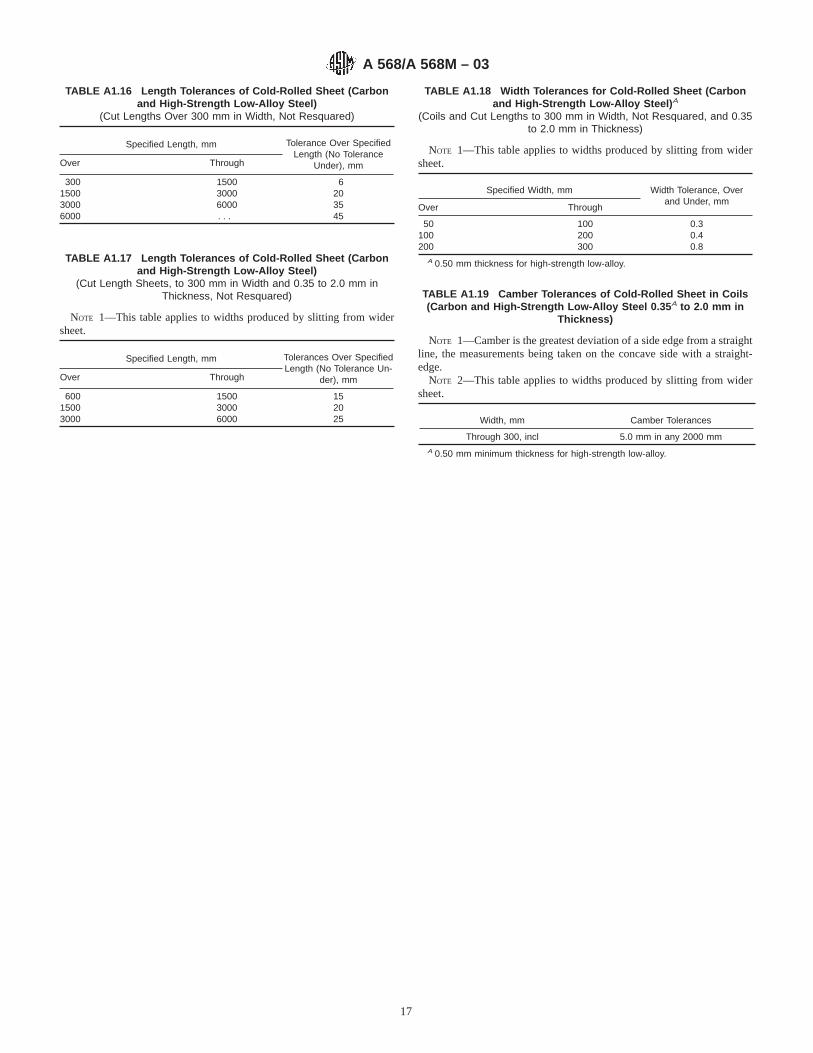
TABLE A1.16 Length Tolerances of Cold-Rolled Sheet (Carbonand High-Strength Low-Alloy Steel)
(Cut Lengths Over 300 mm in Width, Not Resquared)
Specified Length, mm Tolerance Over SpecifiedLength (No Tolerance
Under), mmOver Through
300 1500 61500 3000 203000 6000 356000 . . . 45
TABLE A1.17 Length Tolerances of Cold-Rolled Sheet (Carbonand High-Strength Low-Alloy Steel)
(Cut Length Sheets, to 300 mm in Width and 0.35 to 2.0 mm inThickness, Not Resquared)
NOTE 1—This table applies to widths produced by slitting from widersheet.
Specified Length, mm Tolerances Over SpecifiedLength (No Tolerance Un-
der), mmOver Through
600 1500 151500 3000 203000 6000 25
TABLE A1.18 Width Tolerances for Cold-Rolled Sheet (Carbonand High-Strength Low-Alloy Steel) A
(Coils and Cut Lengths to 300 mm in Width, Not Resquared, and 0.35to 2.0 mm in Thickness)
NOTE 1—This table applies to widths produced by slitting from widersheet.
Specified Width, mm Width Tolerance, Overand Under, mm
Over Through
50 100 0.3100 200 0.4200 300 0.8
A 0.50 mm thickness for high-strength low-alloy.
TABLE A1.19 Camber Tolerances of Cold-Rolled Sheet in Coils(Carbon and High-Strength Low-Alloy Steel 0.35 A to 2.0 mm in
Thickness)
NOTE 1—Camber is the greatest deviation of a side edge from a straightline, the measurements being taken on the concave side with a straight-edge.
NOTE 2—This table applies to widths produced by slitting from widersheet.
Width, mm Camber Tolerances
Through 300, incl 5.0 mm in any 2000 mmA 0.50 mm minimum thickness for high-strength low-alloy.
A 568/A 568M – 03
17

APPENDIXES
(Nonmandatory Information)
X1. AGING EFFECTS ON FORMABILITY OF COLD-ROLLED CARBON-STEEL SHEET PRODUCTS
X1.1 Cold-rolled carbon-steel sheet products exhibit maxi-mum formability in the annealed last, or dead-soft, condition.However, many sheet products are not suitable for exposedapplications in the dead-soft condition because Luder’s lines(sometimes referred to as“ stretcher strains” or “fluting”) maydevelop during subsequent forming. This problem is avoided inmost cases by temper rolling the sheet after annealing. Aftertemper rolling, however, some sheet products are susceptible toaging. Aging refers to a gradual increase in yield strength andcorresponding decrease in ductility during storage after temperrolling. Aging always has a negative effect on formability and,when aging leads to the redevelopment of an upper yield point,can result in renewed susceptibility to fluting.
X1.2 Aging can occur when interstitial solute atoms,carbon or nitrogen, are present in the steel. Solute carbon ornitrogen atoms are those not chemically combined with otherelements in the steel (as carbides or nitrides, for example).Over time, these carbon or nitrogen interstitial solute atomsdiffuse to crystalline imperfections within the steel and, in sodoing, give rise to aging. The extent to which aging occursdepends on the interstitial solute level and the combination oftemperature and time to which the steel is exposed after temperrolling. In general, higher interstitial solute levels result inlarger strength increases during storage; the rate of agingincreases with increasing temperature. As described as follows,the final interstitial solute level and aging characteristicsdepend on the chemical composition of the steel as well asspecific sheet-processing methods used by the steel producer.
X1.3 Low-Carbon Steels—In conventional aluminum-killedlow-carbon steels, the level of interstitial solute is affectedmainly through the formation of aluminum nitride and ironcarbides within the steel during processing, which is influencedby the manner in which annealing is performed.
X1.3.1 Many sheet products are annealed in batches oflarge, tightly wound coils. During heating, any solute nitrogenpresent in the full-hard sheet combines with aluminum to formaluminum nitride. Subsequent cooling is very slow and allowsessentially all of the carbon to precipitate as iron carbide. Finalinterstitial solute levels are very low and, as a result, batch-annealed low-carbon steels have excellent resistance to aging.
X1.3.1.1 Deep drawing steel (DDS) sheet typically is batch-annealed and has excellent aging resistance. With temperrolling, DDS sheet is suitable for use in many exposedapplications with severe forming requirements.
X1.3.2 Cold-rolled low-carbon steels are sometimes pro-cessed in a continuous annealing line, in which the full-hardsheet is uncoiled, passed through an annealing furnace, andthen rewound in a continuous manner. Heating and coolingrates are much higher than those found in batch annealing. Thefaster cooling, in particular, results in higher levels of intersti-tial solute in the product as compared with batch annealing.The manner in which the sheet is cooled can be controlled tominimize the solute carbon level, and temper rolling is effec-tive for reducing fluting tendencies. However, continuous-annealed low-carbon steels are more prone to subsequent agingthan batch-annealed steels.
TABLE A1.20 Flatness Tolerances of Cold-Rolled Sheet (Carbonand High-Strength Low-Alloy Steel) A
(Cut Lengths Over 300 mm in Width)
NOTE 1—This table does not apply when product is ordered full hard,to a hardness range or “annealed last” (dead soft).
NOTE 2—This table also applies to lengths cut from coils by theconsumer when adequate flattening measures are performed.
NOTE 3—Application of this table to product in coil form is notappropriate unless the coil has been rolled out and adequately flattenedwith all coil set removed.
SpecifiedThickness,
mm
Specified Width, mmFlatness Tolerance, mm Speci-fied Yield Point, min, MPa
Over Through Under310 MPa
310 to 345MPaB
Through 1.0 . . . 900 10 20900 1500 15 30
1500 20 40Over 1.0 . . . 900 8 20
900 1500 10 201500 1800 15 301800 . . . 20 40
A Maximum deviation from a horizontal flat surface.B Tolerances for high-strength, low-alloy steel with specified minimum yield point
in excess of 345 MPa are subject to negotiation.
A 568/A 568M – 03
18

X1.3.2.1 Low-carbon commercial steel (CS) and drawingsteel (DS) sheet are available as either batch- or continuous-annealed products, depending on the facilities of a givenproducer. To minimize aging effects in continuous-annealedproducts, rotation of stock by fabricating the oldest materialfirst is recommended.
X1.4 Interstitial-Free Steels—Interstitial-free steels haveessentially no interstitial solutes and, as a result, are nonaging.Processing involves vacuum degassing during refining of theliquid steel, as well as additions of elements that form verystable carbides and nitrides, such as titanium or columbium(niobium). These steps ensure that total interstitial levels arevery low, and that the interstitials are all chemically combined(or stabilized) in the form of alloy carbides or nitrides.Interstitial-free steels are nonaging regardless of whetherannealing is conducted in a continuous or batch manner.
X1.4.1 Extra-deep drawing steel (EDDS) must be vacuumdegassed and stabilized. This nonaging, interstitial-free productis suitable for exposed applications with the most severeforming requirements.
X1.5 Bake-Hardenable Steels—Bake-hardenable steels area special product class with controlled interstitial solute levelsand aging behavior. These steels are processed to have mod-erate aging resistance, to permit forming while the steel is in itsmost ductile condition. Aging occurs largely during a subse-quent thermal treatment (for example, paint-curing), whichresults in desirable hardening of the final part for betterdurability.
X1.5.1 Continuous-annealed low-carbon steels can exhibitsignificant bake-hardening, as well as certain vacuum-degassedand batch-annealed steels.
X2. STANDARD CHEMICAL RANGES AND LIMITS
X2.1 Standard chemical ranges and limits are prescribedfor carbon steels in Table X2.1 and Table X2.2.
A 568/A 568M – 03
19

TABLE X2.1 Standard Steels—Carbon Sheet Steel Compositions
Steel DesignationNo.
Chemical Composition Limits, %
C Mn P max S max
1001 0.01 max 0.35 max 0.030 0.0351002 0.02 max 0.35 max 0.030 0.0351003 0.04 max 0.35 max 0.030 0.0351004 0.02/0.06 0.35 max 0.030 0.0351005 0.06 max 0.35 max 0.030 0.035
1006A 0.02/0.08 0.45 max 0.030 0.0351006 0.08 max 0.45 max 0.030 0.0351007 0.02/0.10 0.50 max 0.030 0.0351008 0.10 max 0.50 max 0.030 0.0351009 0.15 max 0.60 max 0.030 0.0351010 0.08–0.13 0.30–0.60 0.030 0.0351012 0.10–0.15 0.30–0.60 0.030 0.0351015 0.12–0.18 0.30–0.60 0.030 0.0351016 0.12–0.18 0.60–0.90 0.030 0.0351017 0.14–0.20 0.30–0.60 0.030 0.0351018 0.14–0.20 0.60–0.90 0.030 0.0351019 0.14–0.20 0.70–1.00 0.030 0.0351020 0.17–0.23 0.30–0.60 0.030 0.0351021 0.17–0.23 0.60–0.90 0.030 0.0351022 0.17–0.23 0.70–1.00 0.030 0.0351023 0.19–0.25 0.30–0.60 0.030 0.0351025 0.22–0.28 0.30–0.60 0.030 0.0351026 0.22–0.28 0.60–0.90 0.030 0.0351030 0.27–0.34 0.60–0.90 0.030 0.0351033 0.29–0.36 0.70–1.00 0.030 0.0351035 0.31–0.38 0.60–0.90 0.030 0.0351037 0.31–0.38 0.70–1.00 0.030 0.0351038 0.34–0.42 0.60–0.90 0.030 0.0351039 0.36–0.44 0.70–1.00 0.030 0.0351040 0.36–0.44 0.60–0.90 0.030 0.0351042 0.39–0.47 0.60–0.90 0.030 0.0351043 0.39–0.47 0.70–1.00 0.030 0.0351045 0.42–0.50 0.60–0.90 0.030 0.0351046 0.42–0.50 0.70–1.00 0.030 0.0351049 0.45–0.53 0.60–0.90 0.030 0.0351050 0.47–0.55 0.60–0.90 0.030 0.0351055 0.52–0.60 0.60–0.90 0.030 0.0351060 0.55–0.66 0.60–0.90 0.030 0.0351064 0.59–0.70 0.50–0.80 0.030 0.0351065 0.59–0.70 0.60–0.90 0.030 0.0351070 0.65–0.76 0.60–0.90 0.030 0.0351074 0.69–0.80 0.50–0.80 0.030 0.0351078 0.72–0.86 0.30–0.60 0.030 0.0351080 0.74–0.88 0.60–0.90 0.030 0.0351084 0.80–0.94 0.60–0.90 0.030 0.0351085 0.80–0.94 0.70–1.00 0.030 0.0351086 0.80–0.94 0.30–0.50 0.030 0.0351090 0.84–0.98 0.69–0.90 0.030 0.0351095 0.90–1.04 0.30–0.50 0.030 0.0351524 0.18–0.25 1.30–1.65 0.030 0.0351527 0.22–0.29 1.20–1.55 0.030 0.0351536 0.30–0.38 1.20–1.55 0.030 0.0351541 0.36–0.45 1.30–1.65 0.030 0.03515481552
0.43–0.520.46–0.55
1.05–1.401.20–1.55
0.0300.030
0.0350.035
Note—When silicon is required, the following ranges and limits are commonly used.
To 1015, excl 0.10 max1015 to 1025, incl 0.10 max, 0.10–0.25, or 0.15–0.30Over 1025 0.10–0.25 or 0.15–0.30
A 568/A 568M – 03
20

TABLE X2.2 Standard Chemical Ranges and Limits
NOTE 1—The carbon ranges shown in the column headed “Range” apply when the specified maximum limit for manganese does not exceed 1.00 %.When the maximum manganese limit exceeds 1.00 %, add 0.01 to the carbon ranges shown below.
Element
Carbon Steels Only, Cast or Heat Analysis
Maximum SpecifiedElement, %
Range Lowestmax
Carbon (see to 0.15 incl 0.05 0.08Note) over 0.15 to 0.30 incl 0.06
over 0.30 to 0.40 incl 0.07over 0.40 to 0.60 incl 0.08over 0.60 to 0.80 incl 0.11over 0.80 to 1.35 incl 0.14
Manganese to 0.50 inclover 0.50 to 1.15 inclover 1.15 to 1.65 incl
0.200.300.35
0.40
Phosphorus to 0.08 inclover 0.08 to 0.015 incl
0.030.05
0.030A
Sulfur to 0.08 inclover 0.08 to 0.15 inclover 0.15 to 0.23 inclover 0.23 to 0.33 incl
0.030.050.070.10
0.035A
Silicon to 0.15 inclover 0.15 to 0.30 inclover 0.30 to 0.60 incl
0.080.150.30
0.10
Copper When copper is required 0.20min is commonly specified.
A Certain individual specifications provide for lower standard limits for phosphorus and sulfur.
A 568/A 568M – 03
21

X3. PROCEDURE FOR DETERMINING BREAKAGE ALLOWANCE LEVELS (APPLICABLE TO CARBON STEEL SHEETONLY)
X3.1 In spite of the many extra precautions exercised inmaking sheet for drawing purposes, certain manufacturingvariables may be encountered, all beyond the manufacturer’sreasonable control, which may contribute to breakage infabrication and must be considered as part of the normal hazardof the purchaser’s use. The manufacturer will undertake toestablish with the purchaser’s concurrence a breakage allow-ance level.
X3.2 Breakage, for the purpose of this proposal, is definedas unrepairable parts, broken during drawing and classed asscrap. Parts showing laminations, resulting from pipe, may beexcluded provided they are separately identified. Broken partsthat can be salvaged are not covered in this procedure.
X3.3 This procedure is intended to establish a breakageallowance without the need for reinspection of each brokenstamping. It will apply to overall breakage on a given part (ascalculated by the method outlined below) in excess of 1 % upto and including 8 %. Inherent variations in steel and normalvariables in the stamping operation preclude 100 % satisfac-tory performance. Therefore, it is accepted that practicalperfection is attained when 99 % of the stampings are producedwithout breakage. When the overall breakage is in excess of8 %, it is considered to be the result of abnormal stampingconditions, and this method does not apply.
X3.4 When there are two or more suppliers, the recom-mended procedure for determining a breakage allowance for anidentified part is based on the average percentage of breakageof at least 75 % of the blanks run on that part, on one set ofdies, during at least one month (3000 piece minimum). Thetotal production of all suppliers used to obtain this 75 %minimum is to be included in the calculation starting with thebest performance. The average breakage thus determined shallbe considered the allowance for the part.
X3.4.1 Example:
Vendor Parts Produced Parts Scrap % ScrapA 32 466 630 1.94B 27 856 579 2.08C 67 120 1477 2.20D 56 200 1349 2.40E 40 900 1125 2.75F 850 60 7.0511 225 392 total 5220 total 2.32 avg
X3.4.2 Seventy-five percent of 225 392 equals to 169 044;therefore, it is necessary to include the total production ofvendors A, B, C, and D (A+ B + C + D = total production of183 642 parts) since the total of A, B, and C is only 127 442,which is less than 75 % of the total. Total production of 183642 parts (A+ B + C + D) with 4035 parts being rejected,results in a percentage allowance of 2.20 %. On this basis,vendors D, E, and F exceed the allowance.
X4. PROCEDURES FOR DETERMINING THE EXTENT OF PLASTIC DEFORMATION ENCOUNTERED IN FORMING ORDRAWING
X4.1 Introduction
X4.1.1 The preferred method for determining plastic strainis the circle grid and forming limit curve. The scribed squareand change in thickness methods may also be used to evaluatedeformation during the forming of a flat sheet into the desiredshape.
X4.2 Circle Grid Method
X4.2.1 The test system employs photographic or electro-chemically etched circle patterns on the surface of a sheetmetal blank of known “quality” and a forming limit curve forthe evaluation of strains developed by forming in pressoperations. It is useful in the laboratory and in the press room.Selection from the various steels that are commercially avail-able can be done effectively by employing this technique. Inaddition, corrective action in die or part design to improveperformance is indicated.
X4.2.2 The forming limit curve in Fig. X4.1 has beendeveloped from actual measurements of the major (e1) andassociated minor (e 2) strains found in critical areas of produc-tion type stampings. Strain combinations that locate below thiscurve are safe, while those that fail above the curve are critical.For analysis of metal strain on production stampings, one must
recognize that day-to-day variations of material, lubrication,and die settings will affect the strain level. To ensure trouble-free press performance a zone below the forming limit curvebounded by the dashed and solid lines is designated as the“safety band.” Therefore, strain combinations falling below thedashed lines should not exceed the forming limit curve innormal production operations. The left of zero portion of thecurve defines the limiting biaxial tension-compression straincombination while the right side defines the forming limitcurve. Because the production stampings used to develop forforming limit curve represented all qualities of low-carbonlight-gage sheet steel, this single forming limit curve can beused successfully for these products.
X4.2.3 The circle grid method can also be used for otherlow-carbon sheet categories if the following adjustments to theforming limit curve are made:
X4.2.3.1 Material Thickness—As the metal thickness in-creases the forming limit curve shifts upwards in a parallelmanner, 0.2 % (e1) strain for each 0.025-mm increase in metalthickness above 0.75 mm.
X4.2.3.2 Material Properties—When material propertiesare considerably different from that of conventional low-carbon sheet steel (for example, higher strength-low ductility),
A 568/A 568M – 03
22

the forming limit curve is lower. The magnitude of thedowngrade displacement is specific to each material; therefore,current material information should be consulted to determineplacement of the forming limit curve.
X4.3 Procedure
X4.3.1 Obtain a sheet sample of “known quality,” the sheetquality being established by either supplier designation, con-sumer purchase order, or most preferred tensile data obtainedfrom a companion sheet sample.
X4.3.2 Obtain or prepare a negative on stencil with selectedcircles in a uniform pattern. The circles may be 2.5 to 25.0 mmin diameter; the most convenient diameter is 5.0 mm becauseit is easy to read and the gage spacing is short enough to showthe maximum strain in a specific location on the part.
X4.3.3 The sheet metal blanks should be cleaned to removeexcess oil and dirt; however, some precoated sheets can beetched without removing the coating. The area(s) to be etchedshould be determined from observation of panels previouslyformed; generally, the area that has a split problem is selectedfor etching. Normally, the convex side of the radius is gridded.If sufficient time is available, the entire blank may be etched,since valuable information can be obtained about the move-ment of metal in stamping a part when strains can be evaluatedin what may appear to be noncritical areas. Additionally, forcomplex shapes it may be desirable to etch both surfaces ofblanks so that the strains that occur in reverse draws can bedetermined.
X4.3.4 The sheet metal blanks may be etched by a photo-graphic or electrochemical method. In the former method ofphotosensitive solution, for example, 50 % Kodak Photo Resist(KPR) emulsion and 50 % KPR-thinner, is sprayed onto thesheet. The emulsion is dried by baking the sheet at 65°C for 15min or by just standing it for several hours at room temperaturein a dark room. The latter should be employed in materials thatage and, hence, become stronger when baked at 65°C. Thenegative is placed on the emulsion, held intimately in contactwith the sheet, and exposed to a strong ultraviolet light sourcefor 1 to 11⁄2 min. The sheet is developed for 30 to 45 s in KPRdeveloper, rinsed with water, and sprayed with alcohol to setthe resist. It is again rinsed with water and then sprayed withKPR black dye to reveal the etched circles.
X4.3.5 In the electrochemical method, the etch pad issaturated with an appropriate electrolyte. Various electrolytesare available from suppliers of the etching equipment. Someelectrolytes are more effective than others for etching certainsurfaces, such as terne plate and other metallic coated steels. Arust-inhibiting solution is preferred for steel sheets.
X4.3.6 A ground clamp for the transformer of suitableamperage (10 to 50 A is usually used) is fastened to the blankand the second lead is attached to the etch pad. Although thecurrent may be turned on at this time, caution should be takennot to lay the pad on the sheet blank as it will arc. It isadvisable to refrain from touching the metal of the etch pad andthe grounded sheet blank.
FIG. X4.1 Forming Limit Curve
A 568/A 568M – 03
23

X4.3.7 The stencil is placed with the plastic coating againstthe sheet surface in the area to be etched. Wetting the stencilwith a minimum amount of electrolyte will assist in smoothingout the wrinkles and gives a more uniform etch. The etch padis now positioned on the stencil and the current turned on, if itis not already on. Apply suitable pressure to the pad. Only theminimum time necessary to produce a clear etched patternshould be used. The etching time will vary with the amperageavailable from the power source and the stencil area, as well asthe pad area in contact with the stencil. Rocker-type etch padsgive good prints and require less amperage than flat-surfacedpads. Excessive current causes stencil damage.
X4.3.8 The etching solution activates the surface of themetal and may cause rusting unless it is inhibited. After thedesired area has been etched, the blank should be wiped orrinsed, dried, and neutralized.
X4.3.9 The etched blank is now ready for forming. Thelubricants and press conditions should simulate productionsituations. If a sequence of operations is used in forming a part,it is desirable to etch sufficient blanks so that each operationcan be studied.
X4.4 Measurement of Strain After Forming
X4.4.1 After forming, the circles are generally distorted intoelliptical shapes (Fig. X4.2). These ellipses have major andminor strain axes. The major strain (e1) is always defined to bethe direction in which the greatest positive strain has occurredwithout regard to original blank edges or the sheet rollingdirection. The minor strain (e2) is defined to be 90° to the majorstrain direction.
X4.4.2 There are several methods for determining the majorand minor strains of the formed panel. Typical tools are a pairof dividers and a scale ruled in 0.5 mm. For sharp radii, a thinplastic scale that can follow the contour of the stamping can beused to determine the dimensions of the ellipses. (Scales areavailable to read the percent strain directly.)
X4.5 Evaluation of Strain Measurements
X4.5.1 Thee1 strain is always positive while thee2 strainmay be zero, positive, or negative, as indicated on the forminglimit curve chart (Fig. X4.1). The maximume1 and associatede2 values measured in critical areas on the formed part areplotted on the graph paper containing the forming limit curveby locating the point of intersections of thee1, e2 strains.
X4.5.2 If this point is on or below the “safety band” of theforming limit curve, the strain should not cause breakage.Points further below the curve indicate that a less ductilematerial of a lower grade may be applied. Points above the“safety band” show that fabrication has induced strains thatcould result in breakage. Therefore, in evaluation on stampingsexhibiting these strains, efforts should be made to provide ane1, e2 strain combination that would lie on or below the “safetyband” of the forming limit curve. A differente1, e2 straincombination can be obtained through changes of one or moreof the forming variables such as die conditions, lubricants,blank size, thickness, or material grade. It should be noted atthis time that these conclusions are derived from a referencebase being the steel “quality” used to fabricate the gridstamping.
X4.5.3 When attempting to change the relationship ofe1
ande2 strains, it should be noted that on the forming limit curvethe most severe condition for a givene1 strain is at 0 %e2
strain. This means the metal works best when it is allowed todeform in two dimensions,e1 and e2, rather than beingrestricted in one dimension. A change ine2 to decrease theseverity can be made by changing one of the previouslymentioned forming variables of the die design, for example,improving lubrication on the tension-tension side will increasee2 and decrease the severity.
X4.5.4 In addition to the forming limit curve, thee1e2 strainmeasurements may be used to evaluate the material require-ments on the basis of strain gradients, as illustrated in Fig.X4.3, or by plotting contours of equivalent strain levels on thesurface of the formed part. Even when the level of strain isrelatively low, parts in which thee1 strain is changing rapidlyeither in magnitude or direction over a short span on thesurface may require more ductile grades of sheet metal, changein lubrication, or change in part design.
X4.6 Example of Major and Minor Strain Distribution
X4.6.1 A formed panel (Fig. X4.4) with a cross section asshown in Fig. X4.3 is used to illustrate major and minor strain
FIG. X4.2 Major and Minor Strain AxesFIG. X4.3 Graph of Major Strains and Critical Major Strains and
Cross Section of Etched Panel
A 568/A 568M – 03
24

combinations. A plot of the major strain distribution should bemade by finding the ellipse with the largest major strain (circle7) and measuring both the major and minor strains in the rowof ellipses running in the direction of the major strain. Thesolid dots (Fig. X4.3) are the measured major strains for eachellipse. The Xs are the critical major strains as determined fromthe forming limit curve at the corresponding minor strain(intersection of the measured minor strain and the severitycurve).
X4.6.2 Usually a single row of ellipses will suffice todetermine the most severe strain distribution. The resultingstrain distribution plot (Fig. X4.3) illustrates both severity ofthe strain compared to the critical strain limits and theconcentration of strain in the stamping. Steep strain gradientsshould be avoided because they are inherent to fracture sites.
X4.7 Example for Reducing Splitting Tendency
X4.7.1 In an area such as that represented in Fig. X4.3, thesplitting tendency can be reduced as follows:
X4.7.1.1 If the radius of the part in the region of circle 1 isincreased, some strain can be induced to take place in this areawhich will allow the major strain in circle 7 to be reducedsufficiently to bring the strain combination below the criticallimit. This course of action requires no binding nor reshapingof the punch, only grinding in the radius.
X4.7.1.2 The total average major strain required to makethis formation is only 17.5 %; yet in a 5.0-mm circle the strain
is as high as 40 %. The strain distribution curve puts forthgraphically the need to distribute the strain over the length ofthe time by some means as described above.
X4.7.1.3 Change in lubrication can also improve the straindistribution of a stamping. If the strain over the punch iscritical, the amount of stretch (strain) required to make theshape can be reduced by allowing metal to flow in over thepunch by decreasing the friction through the use of a moreeffective lubricant in the hold-down era.
X4.7.1.4 If the part is critical, a change in material mayhelp. That is, a material having a better uniform elongation willdistribute the strain more uniformly or a material having ahigher “r” value will make it possible to “draw” in more metalfrom the hold-down area so that less stretch is necessary toform the part.
X4.8 Scribed Square Method
X4.8.1 The basic technique is to draw a panel from a blankthat has been scribed both longitudinally and transversely witha series of parallel lines spaced at 25.0-mm intervals. The lineson the panel are measured after drawing and the stretch or drawcalculated as the percent increase in area of a 25.0-mm square.This is a fairly simple procedure for panels having generousradii and fairly even stretch or draw. Many major panels fall inthis category, and in these instances it is quite easy to pick outthe square area exhibiting the greatest increase.
X4.8.2 If the square or line to be measured is no longer a flatsurface, place a narrow strip of masking (or other suitable tape)on the formed surface and mark the points which are to bemeasured. Remove the tape, place on a plane surface, anddetermine the distance between the points with a steel scale.
X4.8.3 There will be cases of minor increase in area withmajor elongation in the one direction. In these instances, thepercent elongation should be recorded.
X4.9 Thickness Method
X4.9.1 There are instances when the maximum stretch iscontinued to an area smaller than 645 mm2 or the shape of thesquare has been distorted irregularly, making measurementsdifficult and calculation inaccurate. When either of theseconditions exists, an electronic thickness gage may be used atthe area in question or this area may be sectioned and thedecrease in metal thickness measured with a ball-point mi-crometer. The increase in unit area can be calculated bydividing the original thickness by the final thickness.
X4.9.2 ExampleAssuming the blank thickness to be 0.80 mm and the final
thickness to be 0.60 mm, the increase in unit area would be a[(0.80 − 0.60)/0.80]3 100 = 25 % increase.
FIG. X4.4 Formed Panel and Cross Section
A 568/A 568M – 03
25

X5. ALTERNATIVE METHODS FOR EXPRESSING FLATNESS
X5.1 Introduction and Definitions
X5.1.1 In addition to the conventional expression of flat-ness, the “maximum deviation from a horizontal flat surface”,at least two other flatness parameters have been developed andare in use for characterizing sheet with longitudinal waves orbuckles. These aresteepness indexand flatness index(or“I-unit”), that are illustrated using the example in Fig. X5.1.
X5.1.2 Steepness Index—Fig. X5.1(a) shows a representa-tion of a sheet sample exhibiting edge waves of height,H, andinterval,L. The steepness index value for this sample is defined
as:steepness index = H/L
Often, the steepness value is expressed as a percentage:% steepness = S = (H/L) 3 100
X5.1.3 I-Units—Making a series of lengthwise cuts to thesample in Fig. X5.1(a) relaxes elastic stresses present in thesheet and results in narrow strips of differing lengths, as shownin Fig. X5.1( b). Using the length of one of these strips as areference (Lref), the I-unit value (I) for an individual strip is
defined as:I = ( DL/Lref) 3 105
where:DL is the difference between the length of a given strip and
the reference strip.
X5.1.4 For the special case of waves/buckles that areperfectly sinusoidal in character, the following relationshipapplies:
I 5 FSp2D S H
L DG2
3 105
or:
I 5 24.7S2
Table X5.1 provides I-unit values based on the sinusoidalapproximation for wave heights up to1⁄2-in. (increments of1⁄32
in.) and intervals between 10 and 40 in. (increments of 1 in.).Mathematical relationships between the three representationsof flatness described here are given in Table X5.2; theserelationships can be used to convert between I-unit, % steep-ness, and wave height values (see examples in Table X5.2).
X5.2 Flatness Evaluation Example and Determinationof I-Unit or % Steepness Value
X5.2.1 While the strip is on an inspection table, find thelocations on the strip that are not lying flat on the table. If noflatness deviation can be found, that portion of the coil(head/middle/tail) can be described as flat (that is, zero I-unit orzero % steepness).
X5.2.2 If the coil is not totally flat, the height of thedeviation must be determined and recorded. If the coil has edgewaves, a step gauge (incremented in intervals of1⁄16 or 1⁄32 in.)can be inserted under a wave to determine the height. If the coilexhibits flatness deviation in the center of the strip, a light-weight straight edge can be placed on the highest portion of thebuckle and on the highest portion of the next repeating buckle.The height can then be determined by inserting a step gaugebetween the straight edge and the strip.
X5.2.3 Along with the height, the wave period or waveinterval must also be determined. The wave interval can beobtained by using a standard tape measure or straight edge tomeasure the distance between the highest point of one flatnessdeviation to the highest point of the next repeating flatnessdeviation.
X5.2.4 After determining height and wave interval, eitherthe I-unit or % steepness value can be obtained. To determinethe I-unit flatness, locate the appropriate height and waveinterval in Table X5.1 and read the I-unit value at theintersection of the two measurements. To determine % steep-ness, divide the height by the wave interval and multiply theresult by 100.
FIG. X5.1 Representation of Sheet Sample With Edge Waves ( a)and Strips of Differing Length That Result from Making
Longitudinal Cuts Along the Sample ( b)
A 568/A 568M – 03
26

TABLE X5.1 I-Unit Conversion Chart
A 568/A 568M – 03
27

SUMMARY OF CHANGES
Committee A01 has identified the location of selected changes to this standard since the last issue(A 568/A 568M – 02) that may impact the use of this standard.
(1) A revision was made to Section 3.1.5.(2) The following Tables were revised: Tables 4, 5, 6, 7, 15,and 16.
ASTM International takes no position respecting the validity of any patent rights asserted in connection with any item mentionedin this standard. Users of this standard are expressly advised that determination of the validity of any such patent rights, and the riskof infringement of such rights, are entirely their own responsibility.
This standard is subject to revision at any time by the responsible technical committee and must be reviewed every five years andif not revised, either reapproved or withdrawn. Your comments are invited either for revision of this standard or for additional standardsand should be addressed to ASTM International Headquarters. Your comments will receive careful consideration at a meeting of theresponsible technical committee, which you may attend. If you feel that your comments have not received a fair hearing you shouldmake your views known to the ASTM Committee on Standards, at the address shown below.
This standard is copyrighted by ASTM International, 100 Barr Harbor Drive, PO Box C700, West Conshohocken, PA 19428-2959,United States. Individual reprints (single or multiple copies) of this standard may be obtained by contacting ASTM at the aboveaddress or at 610-832-9585 (phone), 610-832-9555 (fax), or [email protected] (e-mail); or through the ASTM website(www.astm.org).
TABLE X5.2 Flatness Conversion Factors A
NOTE 1— “L” is the wave interval as defined in Fig. X5.1 (a).
I Unit Height % Steep-ness
I Unit (I) 1
2Lp =I 1025 2
p =I 1021
Height (H)(peak topeak) SHp
2L D2105 1
~100 H!L
% Steep-ness (S) 2.5 (p S)2
~LS!100 1
A Examples—( 1) Assume % steepness is given as 1.5 and the correspondingI-unit value is desired. From Table X5.2, I = 2.5(pS)2= 2.5[(3.14)(1.5)] 2 = 55.5.(2) Assume an I-unit value of 25 is given and the corresponding % steepness isdesired. From Table X5.2, S = 2/p(I 3 10−1)1/2= 2/3.14 (25 3 10−1)1/2= 1.0.
A 568/A 568M – 03
28