Embed Size (px)
Citation preview

M-06-05 July 2010
WATER SUPPLIES DEPARTMENT
STANDARD SPECIFICATION M-06-05
FOR
SUPPLY OF LIQUID CHLORINE CONTAINERS
Revision Date: 8.7.2010
- 1
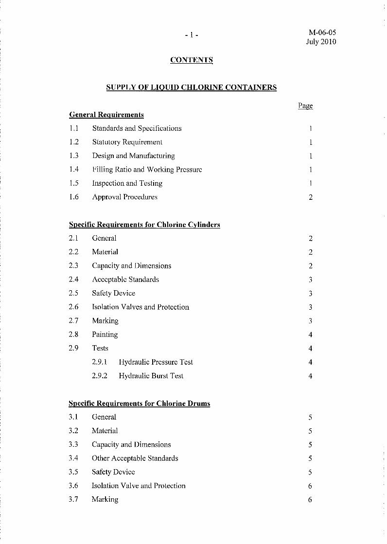
CONTENTS
SUPPLY OF LIQUID CHLORINE CONTAINERS
General Requirements
1.1 Standards and Specifications
1.2 Statutory Requirement
1.3 Design and Manufacturing
1.4 Filling Ratio and Working Pressure
1.5 Inspection and Testing
1.6 Approval Procedures
S~ecific Requirements for Chlorine Cylinders
2.1 General
2.2 Material
2.3 Capacity and Dimensions
2.4 Acceptable Standards
2.5 Safety Device
2.6 Isolation Valves and Protection
2.7 Marking
2.8 Painting
2.9 Tests
2.9.1 Hydraulic Pressure Test
2.9.2 Hydraulic Burst Test
S~ecific Requirements for Chlorine Drums
3.1 General
3.2 Material
3.3 Capacity and Dimensions
3.4 Other Acceptable Standards
3.5 Safety Device
3.6 Isolation Valve and Protection
3.7 Marking
M-06-05 July 2010
Page
1
1
1
1
1
2
2
2
2
3
3
3
3
4
4
4
4
5
5
5
5
5
6
6
M-06-05- 2 July 2010
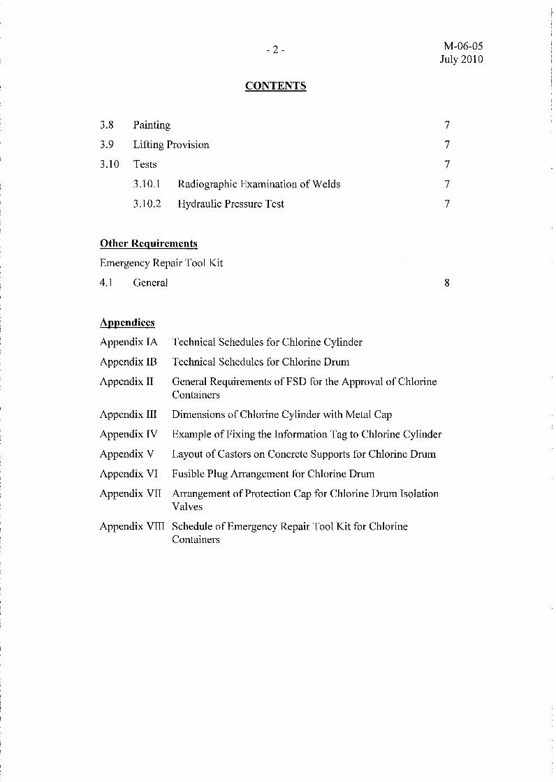
CONTENTS
3.8 Painting 7
3.9 Lifting Provision 7
3.10 Tests 7
3.10.1 Radiographic Examination of Welds 7
3.10.2 Hydraulic Pressure Test 7
Other Requirements
Emergency Repair Tool Kit
4.1 General 8
Appendices
Appendix lA Technical Schedules for Chlorine Cylinder
Appendix IB Technical Schedules for Chlorine Drum
Appendix II General Requirements of FSD for the Approval of Chlorine Containers
Appendix III Dimensions of Chlorine Cylinder with Metal Cap
Appendix IV Example of Fixing the Information Tag to Chlorine Cylinder
Appendix V Layout of Castors on Concrete Supports for Chlorine Drum
Appendix VI Fusible Plug Arrangement for Chlorine Drum
Appendix VII Arrangement of Protection Cap for Chlorine Drum Isolation Valves
Appendix VIII Schedule of Emergency Repair Tool Kit for Chlorine Containers

M-06-05- 1 July 2010
SUPPLY OF LIQUID CHLORINE CONTAINERS
General Requirements
1.1 Standards and Specifications
The liquid chlorine containers (containers) used for storage and transportation of liquid chlorine for the Water Supplies Department (WSD) included chlorine drums (drums) and chlorine cylinders (cylinders). They shall be designed, manufactured and tested in accordance with the latest version of the relevant National Standards generally recognised for supply of liquid chlorine. The general requirements of the containers are briefly described below.
1.2 Statutory Requirement
Under the Dangerous Goods (General) Regulations 64 and 66, Cap. 295B of the Laws of Hong Kong, all chlorine containers are required to be approved by the Director of Fire Services before they are put into use in Hong Kong. As such, the contractor shall ensure that all new containers are in full compliance with this requirement and obtain approval from the Fire Services Department (FSD) for use of the containers in Hong Kong and submit a copy of the approval letter to WSD prior to delivery of the goods.
1.3 Design and Manufacturing
The containers shall be designed and manufactured to a relevant National Standard accepted by WSD as described in Clauses 2.4 and 3.4. The contractor shall provide a copy of the accreditation document/certificate or the prototype approval for chlorine containers of similar capacity or any other certificates from the regulatory authority of the relevant National Standard as a proof of the manufacturer's capability on the design and manufacturing of the containers in accordance with the relevant acceptable National Standard.
In addition, the contractor shall submit the completed technical schedules as shown in Appendices lA and IB for assessment by WSD. The technical details contained therein are by no means exhaustive. The contractor shall add more information as appropriate to enable assessment by WSD on the suitability of the containers to be offered.
1.4 Filling Ratio and Working Pressure
The filling of containers with liquid chlorine shall be in accordance with the Dangerous Goods (General) Regulation 70, Cap. 295B of the Laws of Hong Kong. The filling ratio shall be not greater than 1.19 and the minimum working pressure of the containers shall be not less than 1,950 kPa.
1.5 Inspection and Testing
Inspection and testing of new containers shall be carried out in accordance with the requirements as stipulated in the applied National Standard for the design and manufacturing of the containers as described in Clauses 2.9 and 3.10 and to the

M-06-05- 2 July 2010
satisfaction of an Independent Inspection Body (IIB). A test programme incorporated with details of the testing procedures and the test forms in compliance with the relevant acceptable National Standard and FSD's requirements shall be prepared by the contractor and submitted to WSD for approval prior to conduction of the tests at the manufacturer's works. The approval of the programme shall not relieve the contractor of any of his obligation or liabilities under the contract.
The appointment of the IIB shall follow the requirements as stipulated in WSD Standard Specification EM-OO-Ol. The contractor shall ensure that the IIB employed for inspection and endorsement of the inspection report shall be the recognised IIB accredited by the regulatory authority of the relevant National Standard applicable to the new containers. The contractor shall provide official accreditation proof of the recognized lIB for witness inspection and testing of the containers issued from the regulatory authority of the relevant acceptable National Standard for assessment by WSD.
A full report ofthe prescribed inspections and testing covering each container shall be endorsed by the IIB before they are submitted to the FSD for approval. After approval, one copy of the report shall be forwarded to WSD for reference and record purposes. All the costs associated with the inspection and testing shall be deemed to have been included in the contract price.
1.6 Approval Procedures
The general requirements of FSD for the approval of the containers are attached at Appendix II. The contractor may be required to submit other supporting documents to the satisfaction of FSD in seeking approval for the chlorine containers supplied.
Specific Requirements for Chlorine Cylinders
2.1 General
The materials, design, manufacture, inspection and testing of chlorine cylinders shall be in accordance with the acceptable National Standard as described in Clause 2.4. The cylinders shall be of seamless construction.
2.2 Material
The steel used in the manufacture of the cylinders shall be in accordance with the acceptable National Standard as described in Clause 2.4.
2.3 Capacity and Dimensions
The capacity of the cylinder for supply of liquid chlorine shall be 50 kg. Each cylinder shall have an external diameter of approximately 230 mm and a uniform length not exceeding 1,700 mm. The wall thickness of the cylinder shall be not less than 6 mm or the minimum thickness as specified/calculated from the relevant acceptable National Standard for the cylinders, whichever is the greater. A sketch showing the dimensions

M-06-05- 3 July 2010
of the cylinder is shown in Appendix Ill. The contractor shall provide mill certificate of the steel to be used in manufacturing the cylinders and calculation of the minimum allowable wall thickness of the cylinders according to the relevant acceptable National Standard for assessment by WSD.
2.4 Acceptable Standards
Chlorine cylinders in compliance with one of the following National Standards are acceptable. The contractor shall submit one copy of the relevant National Standard for reference when requested by WSD.
(a) BS EN ISO 9809 - British Standard (b) GB 5099 - Chinese Standard (c) JIS B8241 - Japanese Standard (d) DOT 3A13AA - American Standard
2.5 Safety Device
Each chlorine cylinder shall be provided with a fusible metal plug of either filled type or screwed type at the isolation valve. The fusible metal plug shall act as a pressure relief device for relieving excessive pressure in the event of overheating to prevent rupture. The filled metal of the fusible plug shall be able to withstand the chlorine pressure in the cylinder at or lower than its melting temperature.
2.6 Isolation Valve and Protection
The isolation valves for chlorine cylinders shall comply with the requirements of BS EN ISO 10297 for chlorine applications. The valve body shall be made of forged steel to PD 970 with monel metal valve spindle and PTFE gland packing.
To cope with the standard connections for cylinders, the valve outlet connection shall be right-hand threaded male of size 3/4" BSP. If the outlet connection of other sizes is offered, the container shall be provided with the necessary adapter for the chlorine valve to suit the standard connection.
Each chlorine cylinder shall be provided with a suitably designed metal cap to protect the outlet valve as shown in Appendix Ill. The protection cap shall be in the form of a stout metal cap. The contractor shall submit the design of the protection cap with detailed dimensions to WSD for approval prior to manufacturing of chlorine cylinders.
2.7 Marking
The following markings shall be permanently stamped on the body of each cylinder for identification:
(a) Manufacturer's identification marking (b) Serial number (c) Date of manufacture/Date of 1st test (d) Hydraulic test pressure (e) Water capacity (in litres)

M-06-05- 4 July 2010
(t) Tare weight (g) Weight of chlorine when fully charged (h) Design/Manufacturing standard
An information tag for easy recognition of the particulars of each chlorine cylinder shall be provided, which shall include:
(a) Serial number of the cylinder (b) Tare weight (c) Date of last test/Due date of next test
The information tag can be in the form of an aluminium plate, with the particulars stamped on, enclosed and sealed in a transparent cover, securely tied to a stainless steel flange of 1 mm thick screwed onto the neck of the cylinder as shown in Appendix IV. The contractor can suggest other alternative method of tying the information tag onto the cylinder to WSD for consideration and approval.
2.8 Painting
The cylinders including the protection caps shall be painted in golden yellow colour to BS EN 1089-3. A red dot shall be painted on the hexagonal head of the fusible plug to differentiate it from other solid plugs for easy identification.
The contractor shall ensure that all internal and external screw threads shall be completely free from painting for free turning of the screw threads. The screw threads shall be properly protected prior to application ofpaint, if applicable.
2.9 Tests
Each cylinder shall be tested and examined according to the acceptable National Standard as described in Clause 2.4 and the Dangerous Goods (General) Regulation 66, Cap. 295B of the Laws of Hong Kong, to meet with FSD's requirements for approval of the use of the cylinder in Hong Kong.
2.9.1 Hydraulic Pressure Test
The hydraulic test pressure of the chlorine cylinders shall not be less than the calculated pressure as stipulated in the acceptable National Standard as described in Clause 2.4 or 2,600 kPa as stipulated in the Dangerous Goods (General) Regulation 66, Cap. 295B of the Laws of Hong Kong, whichever is the higher. The contractor shall provide calculation of the minimum required test pressure according to the relevant National Standard for assessment by WSD.
2.9.2 Hydraulic Burst Test
If specified in the Particular Specification, one new cylinder shall be randomly selected for hydraulic burst testing from every batch of new cylinders. Where the number of the new cylinders in the batch exceeds 100 cylinders, one additional cylinder may be taken for the test in every 101 or part thereof.

M-06-05- 5 July 2010
The hydraulic burst pressure for the cylinders shall be not less than the calculated pressure as stipulated in the acceptable National Standard as described in Clause 2.4. The cylinder shall remain in one piece without fragmentation after the testing.
If the randomly selected cylinder failed the hydraulic burst test, two additional cylinders shall be randomly selected from the same batch of new cylinders for repeating the test. If anyone of these two additional cylinders failed the test, the whole batch of new cylinders shall be rejected.
Specific Requirements for Chlorine Drums
3.1 General
The design, manufacture, inspection and testing of the chlorine drums shall be in accordance with the acceptable National Standard as described in Clause 3.4. The drum shall be made from steel plates welded together by electric-arc fusion process.
3.2 Material
The steel used in manufacturing the chlorine drums shall be in accordance with the acceptable National Standard as described in Clause 3.4. The thickness of the steel plate shall be not less than 12 mm or the minimum thickness as specified/calculated from the relevant acceptable National Standard for the drums, whichever is the greater. The contractor shall provide mill certificate of the steel to be used in manufacturing the drums and calculation of the minimum allowable wall thickness of the drums according to the relevant acceptable National Standard for assessment by WSD
3.3 Capacity and Dimensions
The capacity of the drum for supply of liquid chlorine shall be 1,000 kg. The external diameter and the overall length of each chlorine drum shall be approximately 820 mm and 2,080 mm respectively. These dimensions are indicative only but the supported rings of the drum must be suitably spaced for seating on the caster supports as shown in Appendix V.
3.4 Acceptable Standards
Chlorine drums in compliance with one of the following National Standards are acceptable. The contractor shall submit one copy of the relevant National Standard for reference when requested by WSD.
(a) BS EN 14208 - British Standard (b) GB 5100 - Chinese Standard (c) DOT 106A American Standard
3.5 Safety Device
Each chlorine drum shall be provided with at least one fusible plug of screwed type

M-06-05- 6 July 2010
for relieving excessive pressure in the event of overheating to prevent rupture. The fusible plug shall be provided with tapered pipe thread for screwing onto the dome end of the chlorine drum as shown in Appendix VI. The contractor shall advise in the Technical Schedule the number of fusible plug(s) to be provided for each drum according to the applied design standard for the drums to be supplied. The filled metal of the fusible plug shall be able to withstand the chlorine pressure in the drum at or lower than its melting temperature.
3.6 Isolation Valve and Protection
The isolation valve for chlorine drum shall comply with the requirements of BS 341: Part 1 for chlorine applications. The valve body shall be made of forged steel to PD 970 with monel metal valve spindle and PTFE gland packing.
To cope with the standard connections for chlorine drums, the valve outlet connection shall be right hand threaded male of M24. If the outlet connection of other sizes is offered, the drum shall be provided with the necessary adapter for the chlorine valve to suit the standard connection.
Each chlorine drum shall be provided with a suitably designed metal cap to protect the outlet valve. The protection cap shall be in the form of a stout metal cap with thickness not less than 4 mm.
The protection cap of chlorine drums shall be guided by three mild steel lugs welded on the body. The welding of the mild steel lugs shall be strong enough to sustain any possible impact. The raised surface of each lug shall have a tapped hole for insertion of a setscrew for clamping the protection cap in a secured position. The peripheral clearance between the mild steel lugs and the cap shall be not more than 6 mm to ensure full locking of the protection cap by the three setscrews. WSD reserves the right to reject the container if its protection cap is not properly secured by the setscrews. The setscrews for clamping the cap shall be stainless steel of suitable grade.
A sketch showing the configuration for guarding of the chlorine drum by the protection cap is shown in Appendix VII. The contractor shall submit the design of the protection cap with detailed dimensions to WSD for consideration and approval.
3.7 Marking
The following markings shall be permanently stamped on the body of each drum for identification:
(a) Manufacturer's identification marking (b) Serial number (c) Date of manufacture/Date of 1st test (d) Hydraulic test pressure (e) Water capacity (in litres) (t) Tare weight (g) Weight of chlorine when fully charged (h) Design/Manufacturing standard

M-06-05- 7 July 2010
The following identification markings shall be prominently and legibly painted on each drum for easy recognition of the particulars in addition to the stamped markings.
(a) Name of chemical and label of dangerous substance in accordance with the Factory and Industrial Undertakings (Dangerous Substances) Regulations.
(b) Serial number (c) Tare weight (d) Date of last test/Due date for next test (e) Hydraulic test pressure
3.8 Painting
The chlorine containers including the attachment such as the protection cap, lugs and hexagonal screw plugs at the dome ends of drums shall be painted in golden yellow colour to BS EN 1089-3. A red dot shall be painted on the hexagonal head of fusible plug to differentiate it from other solid plugs for easy identification.
The contractor shall ensure that all internal and external screw threads, including the setscrews for clamping the chlorine drum protection cap, shall be completely free from painting for free turning of the screw threads. The screw threads shall be properly protected prior to application of paint, if applicable.
3.9 Lifting Provision
The end rings of the chlorine drum at both ends shall be used for lifting. They shall be designed to have sufficient strength to enable lifting of the drum by hooks.
3.10 Tests
The testing and examination of the chlorine drums shall be in accordance with the acceptable National Standard as described in Clause 3.4 and the Dangerous Goods (General) Regulation 66, Cap. 295B of the Laws of Hong Kong, to meet with FSD's requirements for approval of the use of the drums in Hong Kong.
3.10.1 Radiographic Examination of Welds
100% radiographic examination of all welded seams in accordance with the acceptable National Standard as described in Clause 3.4 shall be performed on every drum to confirm no defect at the welds.
3.10.2 Hydraulic Pressure Test
The hydraulic test pressure of the chlorine drums shall be not less than the calculated pressure as stipulated in the acceptable National Standard as described in Clause 3.4 or 2,600 kPa as stipulated in the Dangerous Goods (General) Regulation 66, Cap. 295B of the Laws of Hong Kong, whichever is the higher. The contractor shall provide calculation of the minimum required test pressure according to the relevant National Standard for assessment by WSD.

M-06-05- 8 July 2010
Other Requirements
Emergency Repair Tool Kit
4.1 General
Where specified in the Particular Specification, one set of emergency repair tool kit manufactured to the requirements as stipulated by the Chlorine Institute for 'emergency kit B' for chlorine drums shall be provided for the chlorine installations of WSD so that immediate action can be taken to temporarily stop the minor leaks from the container by using the tool kit in case of chlorine leakage. Where such requirement is specified, the contractor shall provide a list of recommended repair tool kit with detailed unit cost for each item by completing the Schedule in Appendix VIII for WSD consideration. The items and quantities of tools to be purchased will be at the sole discretion of WSD who also reserves the right not to buy any of them
- End of Specification

M-06-05 July 2010
Appendix lA
Technical Schedules for Chlorine Cylinder
The following Design Data shall be included in the tender document for completion by the tenderers.
Description
(a) Materials - mild steel (i) Yield strength
Specified Requirements Contractor's Offer
(b) Design and manufacture (i) Standard adopted (ii) Working pressure (iii) Thickness (enclosed with calculations
for the thickness of cylinder to the standard adopted in (i) above)
(iv) Designed working pressure (v) Test pressure
Not less than 1,950 kPa Not less than 6 mm
Not less than 2,600 kPa
(c) Nominal chlorine capacity 50 kg
(d) Water capacity, in litres
(e) Filling ratio Not greater than 1.19
(t) Nominal dimensions: (i) External diameter (ii) Overall length
230 mm 1,700 mm
(g) Chlorine isolation valves: (i) Design and construction (ii) Materials (iii) Type of fusible plug (iv) Melting temperature of fusible plug CC)
Filled or screwed type
(h) Screw thread of chlorine valve outlet for connection
3/4" BSP right-hand threaded male
(i) Accreditation certificate for design and manufacturing of chlorine cylinder to the quoted standard mentioned in (b )(i) above
Yes/No
G) Name of lIB for inspection
(k) Accreditation certificate for lIB from the regulating authority for inspection of cylinder to the quoted standard mentioned in (b )(i) above
Yes/No

M-06-05 July 2010
Appendix IB
Technical Schedules for Chlorine Drum
The following Design Data shall be included in the tender document for completion by the tenderers.
Description Specified Requirements Contractor's Offer
(a) Materials - mild steel (i) Yield strength
(b) Design and manufacture (i) Standard adopted (ii) Working pressure Not less than 1,950 kPa (iii) Thickness (enclosed with calculations Notless than 12 mm
for the thickness of drum to the standard adopted in (i) above)
(iv) Designed working pressure (v) Test pressure Not less than 2,600 kPa
(c) Nominal chlorine capacity 1,000 kg
(d) Water capacity, in litres
(e) Filling ratio Not greater than 1.19
(t) Nominal dimensions: (i) External diameter 820 mm (ii) Overall length 2,080 mm
(g) Chlorine isolation valves: (i) Design and construction (ii) Materials (iii) No. of fusible plug(s) to be provided At least one (iv) Melting temperature of fusible plug (QC)
(h) Screw thread of chlorine valve outlet for M24 right-hand connection threaded male
(i) Accreditation certificate for design and YeslNo manufacturing of chlorine drum to the quoted standard mentioned in (b )(i) above
(j) Name of IIB for inspection
(k) Accreditation certificate for IIB from the Yes INo regulating authority for inspection of drum to the quoted standard mentioned in (b )(i) above

M-06-05 July 2010
Appendix 11
General Requirements of FSD for the Approval of Chlorine Containers
Application and Approval Procedure
1.1 All applications for approval of chlorine gas cylinder(s)/container(s) shall be
submitted to the Investigation and Research Section of the Fire Services Department
for processing.
1.2 Every application shall be accompanied by the following supporting documents in
triplicate indicating that the gas cylinder(s)/container(s) submitted for approval have
been manufactured and tested to a standard/design specification acceptable to the
Director of Fire Services.
I) For the gas cylinder(s)/container(s) of a design introduced for use in Hong
Kong in the first time, the following documents shall be provided:
a) fully dimensioned drawing and details of construction of the
cylinder/container;
b) design specifications and calculations, in accordance with the relevant
standard;
c) specifications (e.g. material, design, pressure rating, inlet & outlet threads etc.)
of valve to be used with the cylinders/containers;
d) manufacturer's certificate;
e) inspection report by recognised independent inspection authority/body;
f) report of physical tests and chemical analysis of material used in construction;
g) report on tests carried out in accordance with the standardlcode used;
h) details of any heat treatment;
i) gas( es) to be filled into the cylinders/containers;
j) model/type/serial numbers of the cylinders/containers
II) For the gas cylinder(s)/container(s) of a type previously approved by the
Director of Fire Services, only documents of 1.2 (d) to G) will be sufficient for
assessment provided that the approved design drawing; number of such type/model;
and the Director of Fire Services approval reference can be identified and the type of
container valve remains unchanged.

M-06-05 July 2010
Appendix 11
1.3 The inspection report as mentioned at 1.2( e) should be issued by recognised
independent inspection authority/body authorised by the relevant local regulatory
authority.
1.4 A list of recognised independent inspection authority / body for application of
Approval of Gas Cylinders (both cylinders and drums are applicable)
Name of the inspection authority / body
1 APRAGAZ, Belgium
2 Arrowhead Industrial Services, Inc., USA
3 Authorized Testing Inc., USA
4 Beijing Special Equipment Inspection Center, China
5 Bureau Veritas, Vienna
6 Det Norske Veritas, Norway
7 SAQ Kontroll AB, Sweden
8 T.R. Cochrane Laboratories, Ltd., USA
9 TDv CERT Certification body, Germany
10 TDv Industrie Service GmbH, Germany
11 TDv NORD Czech, S.LO. Germany
12 l:~irti~nlJEj]~~{~J~~pJT,China
13 ~t*rti!f,ffj5)tfffH~~Ur=pI~\,China

M-06-05 July 2010
Appendix III
CYUNDER VALVE WITH FUSIBLE PLUG
THREADED
o <:) o +I '" <:) co n
w230±5(O.D.)
DIMENSIONS OF CHLORINE CYLINDER WITH METAL CAP NOTE:N.T.S. 1, ALL DIMENSIONS IN mm.S4015/30
(Revised on 12.5.2010)

,-(~ CYLINDER VALVE WITH FUSIBLE PLUG o .~ Yl3mm HOLE
I 1 " FOR WIRE
THREADED DIA. TO SUITS.S. FLANGE MINOR DIA OF(SEE DETAIL) CAP THREAD
s.s. FLANGE
INFORMATION TAG
o
SERIAL NO. ____
DATE OF INSPECTION
L1 TARE WT. kg
INFORMATION TAG
>EXAMPLE OF FIXING THE INFORMATION TAG ~~7= -,:;;.,TO CHLORINE CYLINDERS =- '-< ;:;" N ~ )0000;°6N.T.S. <oV)
54015/25
I

ZOIlO APPROX.
SUPPORTED RINGS OF THE DRUM MUST BE SPACED TO SUIT THE
-~_"","~ro-"-_~~ --1 /""'"""
r7 tl! tit \ r OOTH ENDS
:; I[~II +111 \~IIx
~ ~ _ CHLORINE DRUM_ ~_TT·········· 11 ~ 11 lorha..l·
11::i 11 I I
CASTOR I I I I I 1
--~ 181~ ------- "
CONCRETE SUPPORTS _________I ~ . GRD. FL. L.
.'~ <l .• ~ ~ .~.. .~
'" .6..6"" ..0" <:to '4 ~!:
.~ ~ '" 1170
360 360 200 970 200
~ s:: ~ ,=~ILAYOUT OF CASTORS ON CONCRETE SUPPORTS '-<
Q.. °.... N 0\ ~ ° I .............. 0S4015/86 FOR CHLORINE DRUM ,"""Ov.

2080 APPROX.
PROTECTION / SUPPORT RINGS, IF PROVIDED MUST BE SPACED TO SUIT THE CASTORS OF THE CONCERTE SUPPORTS
END RINGS AT BOTH ENDS
CHLORINE DRUM t3 er: a...
_~I____.....L...
o N 00 "&
FUSIBLE PLUG
> ~~7=-,:::.,
IQ.. '-<FUSIBLE PLUG ARRANGEMENT FOR CHLORINE DRUM ~. N §:: ...... 0'""",-<_0SK4015/154 ..... OVl

''0/\\
-H"'rl~ o \ o \I ll\ \ or- \J
yll
~------ 3 NOS. EQUALLY SPACED MILD .... STEEL LUGS WELDED TO DRUM
,-------- PROTECTION CAP ---, (THICKNESS NOT LESS THAN 4mm)
-------::;.\
''0/\
VIEW 'A' ELEVATION
3 NOS. OF STAINLESS STEEL SETSCREWS FOR CLAMPING OF PROTECTION CAP
VIEW 'A'
SECTION 'B' - 'B' > ~'-<7= ~ ,;;:.,Q., - I ... '< 0
~OlARRANGEMENT OF PROTECTION CAP ~NO\
"" ...... 0
SK4015/143 FOR CHLORINE DRUM ISOLATION VALVES =OVl
(Revised on 19.9.2008)

M-06-05 July 2010
Appendix VIII
Schedule of Emergency Repair Tool Kit for Chlorine Containers
The following Schedule of Emergency Repair Tool Kit shall be included in the tender document for completion by the tenderers if such requirement is specified in the tender.
Item Description Recommended Unit Remarks No. Quantity to be Cost
purchased