Embed Size (px)
Citation preview

These specifications are intended for inclusion into the contract documents. They only address the technical specifications and construction details of the referenced section.
STANDARD SPECIFICATIONS FOR
STREET CONSTRUCTION
CITY OF PLYMOUTH, MINNESOTA
JANUARY 2018
ENGINEERING DIVISION
3400 PLYMOUTH BLVD.
PLYMOUTH, MN USA 55447-1482 TELEPHONE (763) 509-5500
Jim Renneberg, P.E.
City Engineer

2018 STANDARD DETAIL SPECIFICATION FOR STREET CONSTRUCTION 02400 - 2
THIS PAGE LEFT BLANK FOR PRINTING

2018 STANDARD DETAIL SPECIFICATION FOR STREET CONSTRUCTION 02400 - 3
SECTION 02400 STANDARD DETAIL SPECIFICATIONS
FOR STREET CONSTRUCTION
CITY OF PLYMOUTH, MINNESOTA USA
JANUARY 2018
INDEX
Print on Grey Paper
02401 SCOPE OF WORK 02402 SPECIFICATIONS WHICH APPLY 02403 STREET CONSTRUCTION MATERIALS
.1 Select Granular Borrow
.2 Geotextile Fabrics
.3 Aggregate Base
.4 Concrete
.5 Plant Mix Bituminous Pavement
.6 Tack Coat
.7 Reflectorized Pavement Markings
.8 Traffic Signs and Devices
.9 Truncated Domes for Pedestrian Ramps 02404 CONSTRUCTION REQUIREMENTS
.1 Working Hours
.2 Excavation
.3 Embankment
.4 Subgrade Preparation
.5 Geotextile Fabric
.6 Aggregate Base
.7 Concrete Curb & Sidewalks
.8 Bituminous Pavement
.9 Tack Coat
.10 Reflectorized Pavement Markings
.11 Traffic Signs and Devices
.12 Traffic Control and Detours
.13 Trails and Parks
.14 Restoration
.15 Criteria for damage Concrete Curb & Flat work replacement for “New Street Warranty Work”.
02405 TESTING .1 Soils Testing .2 Compaction Testing .3 Test Rolling .4 Aggregate and Bituminous Testing .5 Concrete Air Testing

2018 STANDARD DETAIL SPECIFICATION FOR STREET CONSTRUCTION 02400 - 4
.6 Concrete Slump Testing
.7 Concrete Strength Testing
.8 Concrete Mix Design Testing
.9 Bituminous and Concrete Cores 02406 MEASUREMENT AND PAYMENT 02407 STREET DETAIL PLATES
STRT-1 Standard Curb Details STRT-2 Concrete Cross Gutter STRT-3 MnDOT Pedestrian Curb Ramps 01 STRT-4 MnDOT Pedestrian Curb Ramps 02 STRT-5 MnDOT Pedestrian Curb Ramps 03 STRT-6 MnDOT Pedestrian Curb Ramps 04 STRT-7 MnDOT Pedestrian Curb Ramps 05 STRT-8 MnDOT Pedestrian Curb Ramps 06 STRT-9 Concrete Island Approach Nose Detail STRT-10 Concrete Walk Section STRT-11 Private Drive STRT-12 Industrial / Commercial Driveway STRT-13 Residential Driveway Detail STRT-14 Residential Street Section STRT-15 Typical Trail Cross Section STRT-16 Temporary Bituminous CUL-DE-SAC STRT-17 Fire Apparatus Access Road (Fire Lanes) STRT-18 Turnaround Requirements for Dead-End Fire Apparatus
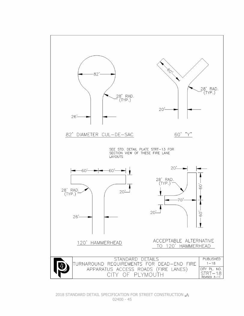
Access Roads (Fire Lanes) STRT-19 Location of Public Utilities STRT-20 Single Trench Installation location of Public Utilities STRT-21 Traffic Sign Specifications STRT-22 Traffic Signs STRT-23 Sign Post Embedment Assembly STRT-24 Street Name Marker STRT-25 Permanent Barricades STRT-26 Park Signs STRT-27 Requirements for Fire Lane Signage on Private Drives STRT-28 Removable Bollard Detail STRT-29 Risers for Extension of Gate Valves & Manholes STRT-30 Typical Right-of-Way Cross Section MnDOT ADA Compliance Curb Ramp Check List

2018 STANDARD DETAIL SPECIFICATION FOR STREET CONSTRUCTION 02400 - 5
02401 SCOPE OF WORK The work to be done under this contract shall include the furnishing of all labor, materials, tools and equipment to perform the grading, soil stabilization, placement of aggregate base, bituminous surfacing, concrete curb and gutter, sidewalk, trails and all appurtenant construction as shown on the drawings and as specified herein. Water applied for grading and compaction of base material shall be incidental to the placement. NO CONCRETE WORK OR BITUMINOUS SURFACING SHALL BE PLACED BEFORE APRIL 15TH OR AFTER OCTOBER 31ST. Bituminous or concrete installation after October 31st must receive approval from the City Engineer and if approved, the street warranty period will be extended one additional year for a total of two years. Any bituminous or concrete installed after October 31st that fails any test or inspection shall be completely removed and replaced as directed by the City Engineer.
02402 SPECIFICATIONS WHICH APPLY All specifications contained herein, including attached detail drawings, together with the construction plans for the designated project or projects and including current versions of those portions of the following specification, as indicated by paragraph or designation number, shall apply: Minnesota Department of Transportation (MnDOT) “Standard Specifications for Construction” including Special Provisions and updates, unless noted otherwise. In the above referenced MnDOT Specifications and the Special Provisions the word State shall also mean the City of Plymouth, Hennepin County, Minnesota, and Commissioner of Highways to read City Engineer or designee, City of Plymouth, 3400 Plymouth Blvd, Plymouth, Minnesota, 55447.
02403 STREET CONSTRUCTION MATERIALS
02403.1 SELECT GRANULAR BORROW -Materials Select Granular borrow shall meet the requirements of MnDOT 3149.2B2. The contractor shall provide Certification of the materials being used and will be required to perform field sampling for gradation test of any bedding materials used as required by the City Engineer. Copies of test results shall be submitted to the City in a timely manner. The source of supply and quality of the material is subject to approval by the City Engineer or a designee, in accordance with MnDOT Specifications 1601 & 1603.

2018 STANDARD DETAIL SPECIFICATION FOR STREET CONSTRUCTION 02400 - 6
02403.2 GEOTEXTILE FABRIC (MnDOT 3733.1 Type V) -Materials Geotextile shall be a woven, nonwoven, or knit fabric of polymeric filaments or yarns such as polypropylene, polyethylene, polyester, or polyamide formed into a stable network such that the filaments/yarns retain their relative position to each other. Knit fabric will only be allowed for use as perforated pipe wrap. The geotextile shall be inert to commonly encountered chemicals and shall be free of any chemical treatment or coating that might significantly reduce porosity or permeability. Geotextile shall be uniform in texture, thickness and appearance, and be free of defects, flaws or tears that would significantly alter its strength or filtering properties. All authorized repairs shall be completed to the satisfaction of the City Engineer or a designee. All rolls of geotextile or geotextile-wrapped perforated pipe shall be delivered to the Project with an opaque plastic covering to prevent degradation due to ultraviolet rays of the sun or contamination with mud, dirt, dust or debris. Rolled geotextile shall be identified by manufacturer, product name, and roll number, both on the outside wrap and inside the core, as well as other requirements of ASTM D4873-02 (Identification, Storage, and Handling). Geotextile shall not be left exposed to the sun for a period in excess of 7 days without being covered by the appropriate protective soil or rock layer. The City Engineer or a designee may require replacement of any geotextile exposed to the sun for periods longer than 7 days or if the geotextile is contaminated with foreign matter. When a geotextile fabric is used for stabilization (Type V) or earth reinforcement (Type VI), the Contractor shall place the fabric with a 2 foot overlap at the seams. 02403.3 AGGREGATE BASE -Materials The source of supply and quality of the material is subject to approval by the City Engineer or a designee in accordance with MnDOT Spec. 1601. The contractor shall provide Certification of the materials being used and will be required to perform field sampling for gradation test of any bedding materials used as required by the City Engineer. Copies of test results shall be submitted to the City in a timely manner. The subgrade stabilization rock for 3 Inch Recycle Minus shall be 70% passing 3”, and 30% between 1 ½” and 3”. All Class 5 aggregate base shall be 100% crushed virgin quarry or mine rock conforming to MnDOT specification table 3138-1 or recycled per specification table 3138-2 can be used as aggregate base. However, the composite aggregate mixture/blend shall not contain sod, roots, plants, building rubble, building brick, wood, and plaster, reinforcing steel or other similar objectionable or deleterious materials and shall be free of lumps or balls of clay. Material quality from the source to be used must be demonstrated prior to use.

2018 STANDARD DETAIL SPECIFICATION FOR STREET CONSTRUCTION 02400 - 7
02403.4 CONCRETE -Materials Concrete mix No. 3F52 MnDOT Specification 2461.2 shall be used for hand placed formed curb and gutter, medians, driveways, cross gutters, sidewalks, pedestrian ramps and medians. Concrete Mix No. 3F32, MnDOT Specification 2461.2 shall be used for an extrusion machine placement of concrete. In the production of concrete, an air entraining agent shall be added to the mix according to MnDOT Specification 2461.2. Calcium chloride may be incorporated into the mix, upon written permission of the City Engineer or a designee, whenever the temperature may be expected to reach 50° Fahrenheit or lower during the 24 hour period following placement of the concrete. If Calcium chloride is used, it shall be introduced into the concrete mix as a slurry at the job site, allowing approximately one (1) minute mixing time. The quantity of calcium chloride added shall be determined by the City Engineer or a designee, but in no case shall it exceed two (2) percent of weight of the cement incorporated into the mix.
.4A ADMIXTURES FOR CONCRETE MnDOT Specification 3113. .4B CALCIUM CHLORIDE Type 1 or 2, MnDOT Specification 3911. .4C PREFORMED EXPANSION JOINT FILLER MnDOT Specification 3702. .4D MEMBRANE CURING COMPOUND Type 2, white pigmented, MnDOT Specification 3754. .4E FORM COATING MATERIAL MnDOT Specification 3902. .4F EPOXY COATED REINFORCING BARS MnDOT Specification 3301
02403.5 PLANT MIX BITUMINOUS PAVEMENT -Materials Bituminous material shall conform to MnDOT Specification 2360. Final mix design and ADT estimate shall be approved by the City Engineer or a designee based upon the following. New Construction:

2018 STANDARD DETAIL SPECIFICATION FOR STREET CONSTRUCTION 02400 - 8
Medium volume roads (ADT >1000) - Wear course mix design shall be 2360 Type SPWEA340C
Low volume roads (ADT <1000) - Wear course mix design shall be 2360 Type SPWEA240C
Medium volume roads (ADT > 1000) - Base/Binder course mix design shall be 2360 Type SPNWB330C
Low volume roads (ADT <1000) - Base/Binder course mix design shall be 2360 Type SPNWB230C
Overlays: Medium volume roads (ADT > 1000) - Wear course mix
design shall be 2360 Type SPWEA340B
Low volume roads (ADT <1000) - Wear course mix design shall be 2360 Type SPWEA240B
Driveways & Trails:
2360 Type SPWEA240B 02403.6 TACK COAT -Materials Tack coat shall conform to MnDOT Specification 2357 02403.7 REFLECTORIZED PAVEMENT MARKINGS -Materials
.7A REFLECTORIZED PAINT Reflectorized Paint, White or Yellow per MnDOT Specification 3501 & 3591. .7B GLASS BEADS Glass beads, moisture resistance, drop-on type for use with acrylic latex traffic marking paint to meet MnDOT Specification 3592. .7C PLASTIC PAVEMENT MARKINGS Preformed plastic pavement markings, white or yellow, 1.5 mm (60 mils) thick, shall be in accordance with the provisions of MnDOT Specification 3354.
02403.8 TRAFFIC SIGNS AND DEVICES -Materials Street and traffic signs shall meet the requirements of MnDOT Specification 3352 for Standard No. 2 Reflective Sheet “3M” DG3 High Intensity”, the Minnesota Manual on Uniform Traffic Control Devices, and Standard Detail Plates STRT-20 through STRT-24.
.8A FLANGED CHANNEL SIGN POSTS The sign supports will be a U channel post, painted green. They will be punched with a 3/8” DIA. – 1” on center holes. The posts will be 2 & 3 Lbs. per foot and 6, 7 or 8 foot in length. All signs up to 18” shall be mounted on 2 U-Channel
2018 STANDARD DETAIL SPECIFICATION FOR STREET CONSTRUCTION 02400 - 9
posts each 2 Lbs., one 7’ long and one 6’ long. The longer post shall be driven in the ground first. All signs up to 30” shall use an 8’ – 3 Lb. post and a 7’ -2 Lb. Post, with the 3 Lb. Post driven into the ground first. All signs over 30” shall use 2 sets of posts. (The heavier post placed in the ground first). All U-Channel posts will be driven 36” into the ground. .8B SIGN POSTS All sign posts located in concrete or bituminous areas shall use the “Minneapolis Style” sign post assembly as shown in Standard Detail Plate STRT-22. .8C BRACKETS The marker bracket used shall be the “Lyle Sign” (E-Series) or approved equal. They shall have a galvanized 5/8” square center rod welded onto the tubular pole cap and will accommodate an ornamental nut on the top of the rod. Star shaped center clips will be used to accommodate facing the sign at different angles (See Standard Detail Plate STRT-23). The top nut, plate holder and post cap shall be green. Sign mounting brackets shall be “Earl F Anderson’s” (BR-5 series) aluminum brackets or approved equal. .8D MARKERS Street name sign materials (markers) shall be “Lyle Sign” E-Series or approved equal. The markers are to be a .080 inch minimum thickness flat aluminum plate, single-faced, fully reflectorized with “3M” DG3 high intensity reflective sheeting. The size is to be 9 inch plates with 6 inch, upper case letters or numbers (suffixes such as: TH, ND, etc., will be 4 inch letters in upper case). No more than three blades per pole shall be used. The markers will have white letters or numbers and border, on green background. All streets that are private will be marked by reversing the colors (green letters on a white background). Series “C” letters shall be used for all markers. If sign exceeds 48” in length, “B” series letters may be used. Note: If the street markers are damaged during the course of construction, it will be the responsibility of the developer to replace it. The City will assume ownership when the project has been accepted by the City and the financial guarantees have lapsed. .8E TUBULAR POLES
2018 STANDARD DETAIL SPECIFICATION FOR STREET CONSTRUCTION 02400 - 10
Tubular poles will be galvanized with a minimum wall thickness of .080 inch. The pole shall have a 2-3/8” outside diameter. The tubular pole will be either 10’ of 12’ long. A 12’ tubular pole will be used for locations where a stop sign is planned or anticipated. The stop sign will be mounted on the same tubular pole as the street marker. The City will determine the locations where stop signs may be installed. All tubular poles will be placed in an augur drilled, 36” deep x 10” diameter concrete footing. At one interval on the tubular pole, either the pole shall be crimped or doweled to prevent the pole from turning in the concrete footing. The placement of the tubes will vary depending on conflicts with utilities or other obstacles. All poles should be placed in the boulevard area 6’ behind the back of the curb. If this cannot be accommodated, placement of the tube should be as close to this requirement as possible. The City will approve all materials, sign names and locations prior to installation. Submit shop drawings for review and approval. No more than three street name signs can be placed on any single pole assembly. It will be the responsibility of the installer to have all underground utilities located prior to starting installations.
02403.10 TRUNCATED DOMES FOR PEDESTRIAN RAMPS –Materials
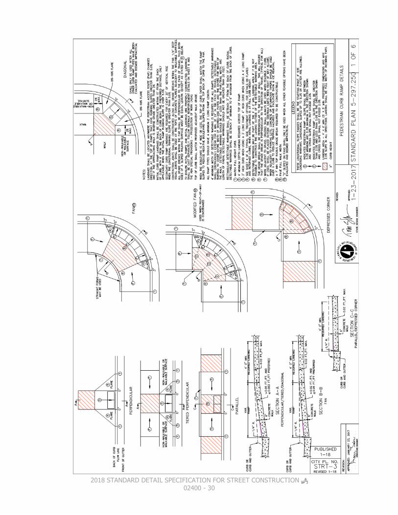
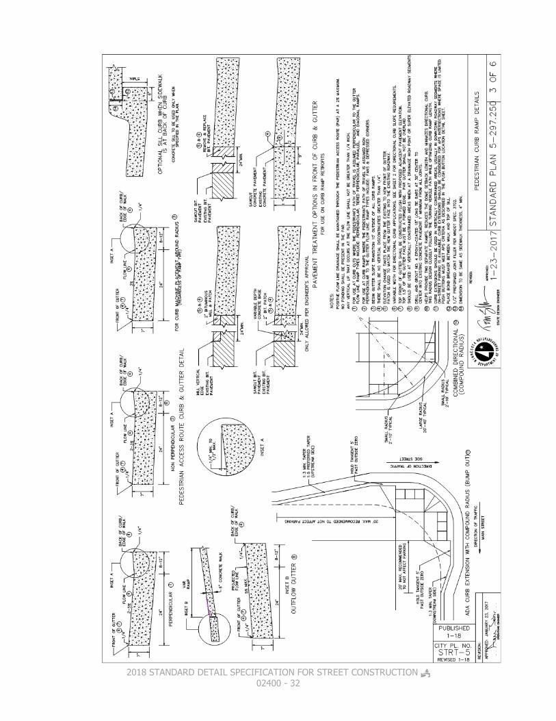
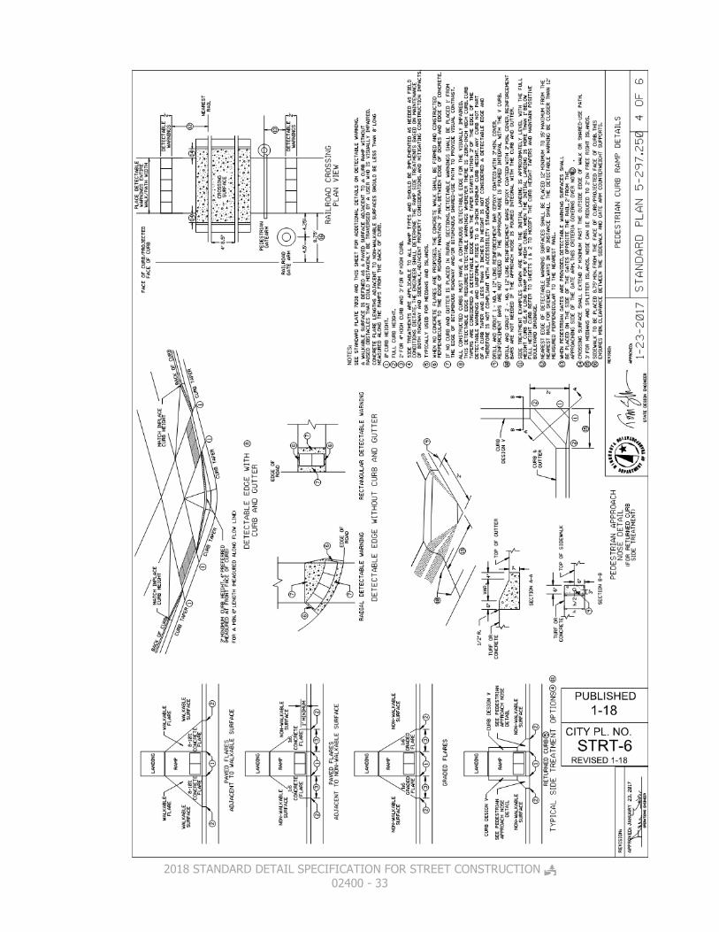
Neenah Foundry Company, East Jordan Iron Works or approved equal from the MnDOT’s approved products page, charcoal grey coated cast iron truncated dome panels shall be used for all pedestrian ramps. Use only one supplier of panels within a project. See Standard Detail Plates STRT-3 through STRT-8.
02404 CONSTRUCTION REQUIREMENTS
02404.1 WORKING HOURS –Construction Requirements The City Engineer or a designee shall be notified at least 48 hours prior to commencing any work. Phone # (763) 509-5500. Contractors are subject to being shut down and or having work rejected if proper notification is not given to the City. Work shall not commence before 7:00 a.m. nor extend beyond sundown Monday through Friday. On Saturdays, work hours are from 8:00 a.m. to 6:00 p.m. No work is permitted on Sundays or Holidays unless authorized by the City. Existing roadways shall not

2018 STANDARD DETAIL SPECIFICATION FOR STREET CONSTRUCTION 02400 - 11
be restricted between 7 & 9 AM and 3 & 6 PM unless approved by the City Engineer. The definition of “Work” also includes the starting of equipment and the delivery of materials to the job site. 02404.2 EXCAVATION –Construction Requirements Roadway excavation shall be performed in accordance with the provisions of MnDOT Specification 2105 except as modified below: The Contractor shall eliminate any and all top soils organic material and non-granular soils from the "subgrade", as directed by the City Engineer or a designee and defined herein as that material below the bottom of the selected granular base material and excavation and fill sections. (Refer to typical sections). Suitable topsoil, (not including sod), which is encountered during excavation may be stockpiled and used as backfill material behind the curb where directed by the City Engineer or a designee. Stockpile locations are to be provided by the Contractor with the approval of the City Engineer or a designee. During construction, all excavation shall be maintained in such a condition that they will be well drained at all times. Temporary ditches or gutters shall be constructed when necessary to maintain drainage and avoid damage to the roadway and existing utilities. No excavated material shall be placed or stockpiled in such a manner as to restrict free surface drainage of the subgrade or base courses. The Contractor shall remove and replace existing signage, guard posts and mail boxes as required. The Contractor shall also install erosion protection devices according to the erosion control plan and or as directed by the City Engineer or a designee. 02404.3 EMBANKMENT –Construction Requirements Roadway embankment shall be performed in accordance with the provisions of MnDOT Specification 2105 except as modified below: Material for embankment shall be obtained from common excavation unless otherwise specified in the special conditions or directed by the City Engineer or a designee. The material used for embankment material may be from excess common excavation material as directed and approved by the City Engineer or a designee. If the required amount of material is more than can be obtained from excess common excavation, the Contractor shall provide additional material from outside sources subject to the approval of the City Engineer or a designee. This material shall be in accordance with MnDOT Specification 2105.2B

2018 STANDARD DETAIL SPECIFICATION FOR STREET CONSTRUCTION 02400 - 12
(CV). All roadway embankments shall be thoroughly compacted in accordance with MnDOT Specification 2105.3F1 “Specified Density Method” unless specifically provided otherwise in the Special Conditions.
“Where this method is specified, the Engineer will sample and test the soils that are to be used, to determine the maximum density and Optimum Moisture, and will make density and moisture tests on the compacted embankment, using methods described in the Mn/DOT Grading and Base Manual. The upper 3 feet of the embankment, together with those portions of the embankment that are below the upper 3 feet but that are adjacent to structures and are subject to the same maximum layer thickness as the upper 3 feet, shall be compacted to a density of not less than 100 percent of maximum density. Those portions of the embankment that are below the upper 3 feet and that are not adjacent to structures shall be compacted to a density of not less than 95 percent of maximum density. At the time of compaction, the moisture content of the embankment material shall be not less than 65 percent nor more than 115 percent of Optimum Moisture where 95 percent of maximum density is required and shall be not less than 65 percent nor more than 102 percent of Optimum Moisture where 100 percent of maximum density is required.”
Subsequent to subgrade preparations and prior to placement or construction of roadbed base material in areas where concrete curb and gutter is to be placed, all backfilling behind the curbing shall have been completed. Any damage inflicted on the subgrade or new construction while placing the embankment shall be repaired by the Contractor at his or her expense. All embankments shall be completed prior to any excess suitable material being disposed of.
02404.4 SUBGRADE PREPARATION –Construction Requirements Subgrade preparation shall be performed in accordance with the provisions of MnDOT Specification 2112 except as modified below: Subgrade preparation shall entail the final shaping and compaction of the subgrade to plus or minus 0.05 feet of proposed elevation and cross section. Any soft spots or displacements which appear during subgrade preparation shall be corrected by scarifying, aerating, or watering

2018 STANDARD DETAIL SPECIFICATION FOR STREET CONSTRUCTION 02400 - 13
and re-compacting as required to obtain stability or by excavating to solid material and backfilling with material suitable for base construction. Unsuitable material, such as vegetation, rubbish, large stones, peat, and wet clay shall be removed and disposed of as directed by the City Engineer or a designee. After correction, the area shall be test rolled as directed by the City Engineer or a designee. Any further roadway work after subgrade preparation may only proceed when all the utility testing has been complete. 02404.5 GEOTEXTILE FABRIC –Construction Requirements Commence installation of geotextile fabric after material has been approved by the City Engineer or a designee and the preparation of the sub-grade has been completed. Install geotextile fabric to the complete limits of the roadway sub-grade including intersections and turning lanes or as directed by the City Engineer or a designee. Unroll geotextile fabric as smooth as possible on the prepared sub-grade in the direction of the construction traffic. Install geotextile fabric in the longest continuous practical length, free from tension, stress, folds, wrinkles and creases. Install geotextile fabric in accordance with this specification and procedures recommended by the manufacturer. Overlap joints a minimum of 2 feet. Install pins or place piles of sub-base material as required to hold geotextile fabric in place. Cut or fold geotextile fabric to conform to curves. Place geotextile fabric to ensure it does not extend more than (4) inches over the sub drain trench. Construction vehicles shall not be permitted to drive on the geotextile fabric. Remove or replace geotextile fabric improperly installed or damaged as directed by the
City Engineer or a designee.
02404.6 AGGREGATE BASE -Construction Requirements
Place aggregate in layers to produce a maximum 3” of compacted thickness. With vibratory compaction, place the produce to a maximum 6” of compacted thickness. Deposit only the amount of aggregate which is intended to be spread and compacted during the same day. Add water as may be required during mixing to produce proper compaction. Replace aggregate for existing gravel driveways with a minimum of 6” or match existing thickness, whichever is greater. Mix aggregate uniformly to maintain proper gradation. Spread and compact each layer to the required cross-section and density prior to placing a succeeding layer. Compact each layer until no visible evidence of further consolidation and to a density not less than 100% of standard proctor density using a steel-wheeled or pneumatic tired roller and a water truck. Construct each course to within 0.05' of the planned grades and staked elevations at all

2018 STANDARD DETAIL SPECIFICATION FOR STREET CONSTRUCTION 02400 - 14
locations. The ENGINEER must be present during tolerance in order to accept the work, but it is the CONTRACTORS responsibility to ensure the acceptable tolerance. 02404.7 CONCRETE CURB, AND FLAT WORK –Construction
Requirements
02404.7A BASE PREPARATION FOR CONCRETE The base for curb and gutter, medians, driveways and sidewalk shall be constructed of materials as shown on the plans and details and shall be well drained and compacted with an approved vibratory compactor to a firm surface with a uniform bearing power. It shall be thoroughly wet down so as to be in a moist condition when the concrete is placed. 02404.7B CONCRETE CURB Concrete curbing shall be in conformance with MnDOT Specification 2531 using B612, B618 or City standard Surmountable type. See Standard Detail Plate Detail_STRT_1. Two (2) No. 4 epoxy coated reinforcing rods MnDOT Specification 3301, shall be placed in the lower portion of the curb twenty feet (20') in length at all sewer and water service trenches, fire hydrant leads and other sewer and watermain trenches. Two (2) ten (10) foot or longer No. 4 epoxy coated reinforcing rods shall also be placed on each side of all catch basins. (See Standard Detail Plates ST-5 & Detail_STRT_1). All initial curbs shall be placed using “Slip Form Machine Placement” except at structure “fill ins”, where the radius is too tight for the machine or as directed by the City Engineer or a designee. 02404.7C CONCRETE SIDEWALKS AND PEDISTRIAN RAMPS Concrete sidewalk pedestrian ramps shall be in conformance with MnDOT Specifications 2521 & 2531 using a 3F52 mix, being a minimum of 5 foot wide and 4” thick standard. Where sidewalk crosses a residential driveway it shall be 6” thick. Where the sidewalk crosses a commercial or private road it shall be 8” thick minimum. See Standard Detail Plate STRT-10. Sidewalks and pedestrian ramps shall be constructed on a 4” thick aggregate base using either CL 5 aggregate base per the detail plate STRT-10. Concrete pedestrian ramps shall be constructed to conform to MnDOT details STRT-3 through STRT-7.
2018 STANDARD DETAIL SPECIFICATION FOR STREET CONSTRUCTION 02400 - 15
Complete the MnDOT ADA compliance Checklist for Curb Ramps for each pedestrian ramp that is installed. The form is included along with the details at the end of this specifications. 02404.7D CONCRETE FINISHING Concrete shall be struck true to cross section as shown on the plans. No additional water may be added to aid in the finishing process. A light broom finish will be required at right angles to the center line on all concrete work unless directed otherwise. All exposed edges and joints in curb, gutter, sidewalk and steps shall be rounded with a suitable edging tool. Before final finishing, the Contractor shall check the concrete with a ten (10) foot steel straight edge to ensure there is no variation greater than 3/16” from the straight edge on tangent lines or grades. If deviations greater than 3/16” are found the work will be considered as unacceptable and will be required to be removed and replaced at no expense to the OWNER. 02404.7E CONCRETE CURING Curing shall be performed by applying a membrane curing compound (Type 2, white pigmented, MnDOT Specification 3754) to the exposed surface of the concrete within one (1) hour after finishing the concrete surfaces. When the forms are removed in less than 72 hours after placing the concrete, the curing compound shall be applied immediately to the exposed surfaces, or the trenches shall be backfilled immediately with suitable backfill material. The rate of application of curing compound shall be 150 square feet per gallon. The compound shall appear as white as a sheet of paper after application on the concrete surface. MnDOT 2531.3 G.3 “Protection against Cold Weather If the national weather service forecast for the construction area predicts air temperatures of 36 °F [1 °C] or less within the next 24 hours and the Contractor wishes to place concrete, submit a cold weather protection plan. Protect the concrete from damage including freezing due to cold weather. Should any damage result, the Engineer will suspend operations until the Contractor takes corrective action, and may subject the damaged concrete to 1503, Conformity with Contract Documents, and 1512, Unacceptable and Unauthorized Work.”

2018 STANDARD DETAIL SPECIFICATION FOR STREET CONSTRUCTION 02400 - 16
02404.7F CONCRETE CONTRACTION/EXPANSION JOINTS –Construction Requirements Preformed expansion joints shall meet MnDOT specification 3702, and shall be provided at the following locations:
At the beginning and end of all curb and gutter radii.
Where new concrete surrounds, adjoins, or abuts any existing fixed objects such as fire hydrants, building foundations, concrete driveways, sidewalks, and other rigid structures.
After each load of concrete when placing curb and every 100 feet when placing sidewalk.
Contraction joints will not be sealed but will be required at a spacing of 10 feet on curb and gutter and 6 foot spacing on sidewalk construction. Contraction joints will be cut to a depth 1/3 the thickness of the concrete, surface and back of all curbs. Contraction joints shall be placed so that no slab is larger than 100 square feet in area. The contractor is responsible for constructing contraction joints that prevent concrete from cracking at other locations. 02404.7G CONCRETE DIMENSIONS AND STRENGTH REQUIREMENTS –Construction Requirements
02404.7G1 Concrete sidewalk will be (5’) wide and a minimum of four (4”) thick with the exception of a six (6”) thickness requirement through residential driveways, and eight (8”) thickness requirements through industrial/commercial driveways, unless specified otherwise on the plans or Special Conditions. Concrete sidewalk steps shall be equal in width to the existing or new sidewalk. Residential concrete steps shall have an eight (8”) rise per step and a nine (9”) tread and commercial concrete steps shall have a seven (7”) rise per step and an eleven (11”) tread.
02404.7G2 Random concrete cylinders will be taken for 7 & 28 day compression strength tests at the rates addressed in the testing portion of this specification. Prior to final acceptance of the work, the City may take cores at random at any suspected weak spots from the concrete to determine thickness and strength.

2018 STANDARD DETAIL SPECIFICATION FOR STREET CONSTRUCTION 02400 - 17
Where the compressive strength is less than 4500 p.s.i. for 3F32 & 3F52 mixes, after 28 days, the City will designate whether or not such defective concrete must be removed and replaced at the Contractor's expense. Where the concrete strength is less than 4500 p.s.i., additional cores shall be taken at the Contractor's expense to determine the extent of such deficiency.
02404.7H EXISTING CONCRETE REMOVALS Replace sections of concrete curb and gutter within 48 hours of removal. Friday removals should be avoided unless they can be replaced that same day.
Completely remove concrete as marked by the ENGINEER.
A clean, vertical edge, approved by the ENGINEER, is required for all removals.
Sawcut curb to at least 1/2 the curb thickness where 1/2 or more of the existing curb section does not require removal.
Sawcut concrete at locations directed by the ENGINEER to provide a clean joint or limit removal.
Protect concrete not designated for removal.
Protect landscaping adjacent to concrete removed. Replace disturbed landscaping in kind. Landscaping restoration shall be considered incidental to curb placement.
Protection including temporary relocation of mailboxes and posts to facilitate construction is incidental to curb installation unless otherwise noted. Damaged mailboxes will be replaced by the CONTRACTOR at the CONTRACTOR’S expense.
02404.8 BITUMINOUS PAVEMENT –Construction Requirements
02404.8A RESTRICTIONS –Construction Requirements Bituminous surfaces shall be placed and rolled only during daylight hours and over a dry road surface. MnDOT 2360.3 D.2.c Mixture Temperature Refer to Table 2360-26, ―Minimum Temperature Control for the minimum laydown temperatures in all courses of the asphalt mixture as measured behind the paver or spreading machine. Do not pave when the air temperature is less than 32° F [0° C] unless otherwise directed by the Engineer in writing.

2018 STANDARD DETAIL SPECIFICATION FOR STREET CONSTRUCTION 02400 - 18
Under no circumstances will bituminous wear be allowed to be placed until all gate valves can be keyed and all valve boxes and manholes castings have been raised. Mixture shall not be placed when, in the opinion of the City Engineer or a designee, the weather or roadway conditions are considered unfavorable. Final wear course placement will be allowed in a new housing development only after one freeze – thaw cycle and after 75% of all units have been issued a certificate of occupancy (C.O.). Placement of wear course on non-housing projects shall be after one freeze – thaw cycle or by the direction of the City Engineer. An inspection of the roadway will be performed by the City Engineer or a designee prior to wear course placement. From this inspection, any deficiencies or damage to the street, sidewalk and curb will be noted and will need to be corrected prior to the placement of the wear course.
1) The developer after the first freeze the cycle and upon approval of the City Engineer, may pave the final wear course prematurely provided the street line items in the developments “Letter Of Credit” remains at 80% of their original amount until they are accepted. The streets acceptance process will remain unchanged and begin once 75% of the development units have a C.O. An inspection of the roadways, sidewalks and trails will be performed at that time and any repairs found, be corrected. If more than 50% of the curb is replaced, per specification section (2404.15J) we will also require that all the wear course be milled off and all the curb and wear course be replaced.

2018 STANDARD DETAIL SPECIFICATION FOR STREET CONSTRUCTION 02400 - 19
02404.8B BASE PREPARATION –Construction Requirements Final shaping and compaction of the aggregate base shall be done just prior to construction of the plant mix bituminous surface. The finished surface of the base shall show no variation greater than 1/2 inch from a ten (10) foot straight edge laid parallel or perpendicular to the center line of the roadway.
02404.8C PLACEMENT OF PLANT MIX BITUMINOUS SURFACE –Construction Requirements Mixture shall be spread without segregation, at the specified rate to the cross section shown in the plans and per MnDOT Specification 3151. See Standard Detail Plate STRT-14. The thickness of each bituminous course shall be within 1/4 inch of the thickness as shown on the plans. The total thickness of all bituminous courses shall be within 1/2 inch. Adjust all surface courses to not greater than ¼” above adjacent curb front edges, or ½” above manhole frames, valve boxes or other fixed structures. Prior to constructing the bituminous binder and/or wearing courses, the Contractor shall sweep the streets. The sweeper shall be a self-propelled pick-up (with water) sweeper. A side-throw sweeper will not be allowed. All areas to be patched with bituminous wear course shall be saw cut. All areas to be patched in the base course can be either saw cut or jack-hammered out. A minimum of 12" shall be maintained around structures and only square or rectangular shaped areas are acceptable. Bituminous patching shall be done in lifts not to exceed 3 inches per lift. A vibratory compactor shall be used. All manholes, gate valves, catch basins, etc. shall be covered to prevent adherence of the bituminous. Suitable covering includes plywood disks, or other approved methods. Castings and pick holes shall be clean of bituminous after each paving operation. 02404.8D COMPACTION –Construction Requirements All pavements will be compacted in accordance with MnDOT Specification 2360.3.D.1 “Maximum Density Method” unless otherwise specified in the Special. After compaction, the

2018 STANDARD DETAIL SPECIFICATION FOR STREET CONSTRUCTION 02400 - 20
thickness of each course shall be within plus or minus ¼” of the thickness shown on the plans for that course. 02404.8E CONSTRUCTION JOINTS –Construction Requirements The longitudinal joint in the center of the road will be made last and shall overlap any previous laid bituminous course longitudinal joint by at least six (6) inches. Transverse joints in adjacent strips shall be separated by a minimum of five (5) feet. Connections to an existing asphaltic mat shall be allowed only after the existing mat has had a vertical joint prepared for final connection. This joint shall be constructed by milling the existing surface in accordance with MnDOT Specification 2232, mill pavement surface. The milled horizontal distance into the existing bituminous shall be at least 6" in width and 2" in depth. Any other method in providing the connections shall first be approved by the City Engineer or a designee. All costs for milling operations shall be considered incidental to the paving costs.
02404.9 TACK COAT –Construction Requirements Coordinate application to allow traffic movement in at least one direction without pick-up or tracking. Provide warning signs indicating “FRESH OIL” if bituminous is not to be placed immediately after tack coat has been applied. Limit application to only the area on which the subsequent course will be placed on the same day. Areas not paved on the same day will have to be re-tacked with no additional compensation. The contact surfaces of curbs, concrete pavement or other fixed surfaces, and transverse joints shall be sprayed with a uniform coat of tack coat material. The rate of Tack coat application shall be per MnDOT specification 2357.3 D table 2357-2. Apply on a clean surface with all preparation work completed prior to placement. Protect adjacent curb and gutter, sidewalk and other exposed surfaces from overspray. Do not apply during or immediately prior to precipitation. Do not apply to wet surfaces. Sand applied at pedestrian crossings will be considered incidental. Protect tacked surfaces from dust, debris and water. Apply materials with a distributor meeting the requirements of MnDOT 2360.3.B.2.d. Temperature of the material at application shall be in accordance with MnDOT 2357.3.E.

2018 STANDARD DETAIL SPECIFICATION FOR STREET CONSTRUCTION 02400 - 21
02404.10 REFLECTORIZED PAVEMENT MARKINGS –Construction Requirements
02404.10A PREPARATION OF PAVEMENT At the time of applying the marking material, the application area shall be dry and free of all contamination, including oil, dirt, grease, curing compound and other matter that might adversely affect adhesion or durability of the marking material. Cleaning shall be accomplished with rotary brooms, air blast, hand brooms, scrapers or whatever combination of equipment that is necessary to produce a clean surface without damage. Particular care shall be taken to remove vegetation and soil from the areas to be edge striped. Should other methods fail, hand scraping or brushing will be required to secure an acceptable surface.
02404.10B APPLICATION EQUIPMENT – PAINT Application equipment for painted markings shall consist of a machine of the spray type capable of applying the paint under pressure at a controlled temperature through nozzles equipped with remotely controlled cut-off mechanisms and suitable line guides that will produce clean cut lines and prevent excessive paint drift. Except where the use of portable sprayers is specifically approved by the City Engineer or a designee, the marking stripes shall be applied with truck mounted traveling units properly equipped to apply the paint stripes as required. Where two or more lines are to be applied at closely controlled spacing (such as double solid lines), the machine shall be equipped to apply those stripes simultaneously. For application of skip lines, the spray unit shall include an automatic control device capable of being set to produce the specified stripe to gap ratio. The paint tanks mounted on the traveling unit shall have provisions for continuous agitation and mixing for the marking material during application. If necessary to maintain uniform flow and application, the paint tank shall be equipped with heating facilities capable of heating and automatically controlling the paint temperature within acceptable limitations as recommended by the paint manufacturer. 02404.10C METHOD OF APPLICATION – PREFORMED PLASTIC PAVEMENT MARKINGS Preformed plastic markings shall be in accordance with MnDOT Specification 3354 and inlaid as recommended by the material manufacturer at the locations indicated on the plans

2018 STANDARD DETAIL SPECIFICATION FOR STREET CONSTRUCTION 02400 - 22
or specifications. The Contractor shall use a certified installer of the pavement marking material. 02404.10D PROTECTION OF TRAFFIC AND MARKINGS Furnish and install all necessary warning and directional signs and devices in order to maintain traffic wherever pavement markings are applied in the presence of traffic, and to protect uncured markings as needed without damaging markings. When necessary, a pilot car and flaggers shall be used to provide adequate control and direction of traffic. Warning signs and barricades shall be placed only where marking operations are in progress, shall be relocated as often as necessary, and shall not be left in place overnight. Traffic shall be allowed to keep moving at all times and the striping equipment shall be operated in a meaner that will not make it necessary for traffic to cross uncured markings. Protective devices such as “cones” shall be of an approved type that will not cause damage to the vehicle when accidentally struck. Protect traffic and markings in accordance with applicable details of the Field Manual. 02404.10E RESTRICTIONS Painted pavement markings shall only be applied in seasonable weather when the air temperature is 50° F. or higher and shall not be applied when there is any moisture on the pavement surface or when the wind or other conditions cause a film of dust to be deposited on the pavement surface after cleaning and before the marking material can be applied. The filling of paint tanks, pouring of paint or cleaning of equipment shall not be performed on unprotected pavement surfaces unless adequate provisions are made to prevent spillage of paint. Application of pavement markings during hours of darkness will only be allowed after approval of the City Engineer or a designee. On pavements open to traffic, the work may be suspended by direction of the City Engineer or a designee during peak traffic hours or at any other time traffic is being unduly hampered or delayed by the work in progress.
02404.11 TRAFFIC SIGNS AND DEVICES –Construction Requirements Traffic signs including street name, warning and regulatory signs shall conform to the MN MUTCD manual. See detail plates STRT21 through STRT-27 for further information. New traffic and street

2018 STANDARD DETAIL SPECIFICATION FOR STREET CONSTRUCTION 02400 - 23
signs shall be installed in new developments once the roadways are in service. If a delay is anticipated in installation of the permanent signs, temporary sign shall be installed in the interim at the contractor’s expense. 02404.12 TRAFFIC CONTROL AND DETOURS –Construction
Requirements
All traffic control shall be in conformance with the Minnesota Manual on Uniform Traffic Control Devices (MN MUTCD), “Temporary Traffic Control Zone Layouts Field Manual, Current Edition” and or as directed by the City Engineer or a designee. Traffic control plans shall be submitted to the City Engineer or a designee for approval prior to implementation. Closures and Detours need 10 working days minimum prior notice before they can be implemented. Contact the City Engineering Division at (763) 509-5500 for assistance in implementation of an approved plan. 02404.13 TRAILS AND PARKS –Construction Requirements Soil sterilants shall be used where necessary under the trails as determined by the Parks and Recreation Department. All trees, stumps, brush, etc., shall be cleared out within four (4) feet of the edge of the trail, except for hardwood trees or others that the plan shows to remain. Trails are to be installed when the adjacent street is constructed. Two rolls of sod will then be placed along both sides of the trail. See Standard Detail Plate STRT-15. 02404.14 RESTORATION –Construction Requirements All seeding and sodding shall be performed in conformance with MnDOT Specification 2575 (Establishing Turf and Controlling Erosion). All disturbed areas must be covered by a minimum of 4” of topsoil, free of unsuitable materials, prior to turf establishment. Slopes steeper than 4:1 shall be stabilized with wood fiber blanket in accordance with MnDOT Specification 2575.3K2. 02404.15 CRITERIA FOR DAMAGED CONCRETE CURB, AND FLAT WORK REPLACEMENT FOR NEW STREET WARRANTY WORK –Construction Requirements The following criteria shall be used to determine concrete curbing and flat work that must be removed and replaced prior to wear course paving. Its primary use is for the markup of damaged curb or sidewalks that are in a new residential development. It can be referenced for use on any project at the engineer’s discretion. City staff will mark all the concrete sections that need to be removed and replaced. All concrete areas must be clean prior to inspection and marking.

2018 STANDARD DETAIL SPECIFICATION FOR STREET CONSTRUCTION 02400 - 24
Glossary Control Joints: Expansion and contraction joints installed by the
contractor during curb and sidewalk construction.
Gouges: Portions of concrete that are missing due to
damage to the curb section during or subsequent to curb construction. Gouges shall be measured from the front edge, back edge or top of curb to the maximum projection of the gouge both into and along the curb section.
Flat Work: Includes sidewalks, aprons, driveways, cross
gutters and medians.
CURB AND FLAT WORK DAMAGE CRITERIA
.15A All curb and flat work panels that have visible cracks at locations other than control joints shall be replaced. (No Saw & Seal) .15B All curb and flat work panels that have settled shall be replaced. (No mud jacking will be allowed) .15C A minimum of two consecutive non-damaged curb or flat work panels is required between panels identified for replacement; i.e. a non-damaged panel between two damaged panels shall also be identified as damaged curb and shall be replaced. .15D All curb and flat work replacement shall be full panels unless otherwise directed by City Engineer. .15E Horizontal or vertical alignment offsets of curb and flat work panels at control joints greater than 3/8” will require curb replacement to correct the offset. .15F Curb and flat work panels with street side/front edge damage shall be removed and replaced if the damage meets the following criteria:
Curb and flat work with horizontal gouges greater than 1” from the street edge regardless of vertical gouge depth.
Curb and flat work with horizontal gouges between ½” and 1” from the street edge with a cumulative length along the curb panel greater than 6” regardless of vertical gouge depth.

2018 STANDARD DETAIL SPECIFICATION FOR STREET CONSTRUCTION 02400 - 25
.15G Curb panels with house side/back edge damage, adjacent driveways or other hard surfaces, shall be removed and replaced if the damage meets the following criteria:
Curb with horizontal gouges greater than 1” from the curb edge regardless of vertical gouge depth
Curb with horizontal gouges between ½” and 1” from the curb edge with a cumulative length along the curb panel greater than 6” regardless of vertical gouge depth.
.15H Curb panels with house side/back edge damage, adjacent sod/landscaped areas, shall be removed and replaced if the damage meets the following criteria: Curb with horizontal gouges 2” or greater from the curb
edge regardless of vertical gouge depth. Curb with horizontal gouges between 1” and 2” from the
curb edge with a cumulative length greater than 1’ regardless of vertical gouge depth.
.15I Curb and flat work panels with top surface damage shall be removed and replaced if the damage meets the following criteria:
Curb and flat work with vertical gouges or scrapes 1” or greater regardless of horizontal length.
Curb and flat work with vertical gouges or scrapes between ½” and 1” with a cumulative horizontal length greater than 1’.
.15J Partial curb panel replacement shall not be allowed if the percentage of curb panels to be replaced exceeds 50% of the total curb length of each block. When the amount of curb damage exceeds 50% of the total block curb length, 100% of that’s block’s curb must be removed and replaced per City standards. The City reserves the right to determine the street segment or length to which the 50% rule will be applied.
02405 TESTING The City shall be copied on all test reports. Samples shall be taken in rates called out in this section or as directed by the City Engineer or a designee or addressed in the special provision for this project. All testing will be considered incidental unless otherwise noted.
02405.1 SOILS TESTING Soil tests required to determine 20-year pavement design. Unsuitable soils shall be excavated and recommendations made for the necessary corrective work. See Standard Detail Plate STRT-14. 02405.2 COMPACTION TESTING

2018 STANDARD DETAIL SPECIFICATION FOR STREET CONSTRUCTION 02400 - 26
Compaction tests on sub-grade and base courses shall be in accordance with MnDOT Specification 2105.3F1.
02405.3 TEST ROLLING Test rolling shall be performed in accordance with the provisions of MnDOT Specification 2111 except as modified below. Perform test rolling after subgrade or aggregate base is established to the proposed width and is within specified tolerance of the staked grades at all locations. Test rolling will be required on all new street sub grades prior to placement of the roadway structural section. On roadway reconstruction projects the Engineer will decide whether to test roll the subgrade or aggregate base. Test rolling may also be required on bituminous or concrete trails and sidewalks. This will be determined in the field by the City Engineer or a designee prior to placing the trail or sidewalk section. The City Engineer or a designee, Project Engineer designee and a Soils Engineer shall be present to witness the test. The Contractor shall provide a loaded tandem axle truck with a minimum gross weight of 25 tons. The Contractor shall provide a weight ticket for the test roll vehicle to the City Engineer or their designee prior to the test roll.
The test rolling shall be at the direction of the City Engineer or their designee. A Soils Engineer will be present during test rolling and provide a written certification to the City that the test passed or what corrections or recommendations are necessary if there is a failure. The City may also require test rolling of the aggregate base, once the base section has been constructed. The City Engineer or a designee may require a subgrade stabilization, geotextile fabric, or subgrade excavation where poor subsoils exist. The Contractor’s Soils Engineer shall evaluate these conditions, and a recommendation made to the Engineer. The expense of test rolling shall be incidental to construction of the roads or walks unless otherwise modified in the contract documents. Protect all culverts and other structures during test rolling. Provide additional cover as required over in place structures as protection during test rolling. Replace structures damaged during test rolling. After completing the test rolling, heavy traffic shall be prevented from using the subgrade until it is covered with the required sand and aggregates. Truck traffic shall not use the subgrade when delivering the sand and aggregate to construct the road section. All loads shall be dumped, pushed and spread over the newly prepared and tested subgrade.

2018 STANDARD DETAIL SPECIFICATION FOR STREET CONSTRUCTION 02400 - 27
02405.4 AGGREGATE AND BITUMINOUS TESTING Roadway aggregate gradation testing shall be as specified in MnDOT Specification 2211. One test for gradation for each 500 tons of material delivered. All bituminous testing shall be in accordance with MnDOT Specification 2360. The test procedure shall be the Quality Assurance (QA) method for streets, and the Quality Control (QC) method for patching, driveways, parking lots, and trails. The contractor shall provide an independent, MnDOT trained and certified, testing company to provide QA testing for the Engineer. All testing shall be paid for by the contractor. 02405.5 CONCRETE AIR TESTING Concrete Air - in accordance with MnDOT Specification 2461 Test the first load of the day and one test per every 100 cubic yards placed thereafter. 02405.6 CONCRETE SLUMP TESTING Concrete Slump - in accordance with MnDOT Specification 2461 Test the first load of the day and one test every 100 cubic yards placed thereafter. 02405.7 CONCRETE STRENGTH TESTING Concrete Strength - MnDOT Design 3F52 Take one set of cylinders per day minimum regardless of quantity. Cylinders sets shall be taken per every 100 cubic yards placed. 02405.8 CONCRETE MIX DESIGN TESTING Concrete mix design shall be prepared by testing laboratory and submitted to the City Engineer or a designee for approval. 02405.9 BITUMINOUS AND CONCRETE CORES Bituminous and concrete cores may be taken as determined by the City Engineer or a designee. The cores shall be taken at any locations within the roadway or trail as directed by the City Engineer or a designee. The contractor shall pay the cost of all core tests and any corrections required by the City.
02406 MEASUREMENT AND PAYMENT
All items will be measured separately according to design designation as indicated in the Pay Item name and as may be detailed and defined in the Plans, Specifications, or Special Provisions. Complete-in-place items shall include all component materials/parts thereof as described or required to complete the unit, but excluding any excesses covered by separate Pay Items.
02407 STREET DETAIL PLATES
STRT-1 through STRT-30

2018 STANDARD DETAIL SPECIFICATION FOR STREET CONSTRUCTION 02400 - 28

2018 STANDARD DETAIL SPECIFICATION FOR STREET CONSTRUCTION 02400 - 29
2018 STANDARD DETAIL SPECIFICATION FOR STREET CONSTRUCTION 02400 - 30

2018 STANDARD DETAIL SPECIFICATION FOR STREET CONSTRUCTION 02400 - 31
2018 STANDARD DETAIL SPECIFICATION FOR STREET CONSTRUCTION 02400 - 32
2018 STANDARD DETAIL SPECIFICATION FOR STREET CONSTRUCTION 02400 - 33

2018 STANDARD DETAIL SPECIFICATION FOR STREET CONSTRUCTION 02400 - 34

2018 STANDARD DETAIL SPECIFICATION FOR STREET CONSTRUCTION 02400 - 35

2018 STANDARD DETAIL SPECIFICATION FOR STREET CONSTRUCTION 02400 - 36

2018 STANDARD DETAIL SPECIFICATION FOR STREET CONSTRUCTION 02400 - 37

2018 STANDARD DETAIL SPECIFICATION FOR STREET CONSTRUCTION 02400 - 38

2018 STANDARD DETAIL SPECIFICATION FOR STREET CONSTRUCTION 02400 - 39

2018 STANDARD DETAIL SPECIFICATION FOR STREET CONSTRUCTION 02400 - 40

2018 STANDARD DETAIL SPECIFICATION FOR STREET CONSTRUCTION 02400 - 41

2018 STANDARD DETAIL SPECIFICATION FOR STREET CONSTRUCTION 02400 - 42

2018 STANDARD DETAIL SPECIFICATION FOR STREET CONSTRUCTION 02400 - 43

2018 STANDARD DETAIL SPECIFICATION FOR STREET CONSTRUCTION 02400 - 44
2018 STANDARD DETAIL SPECIFICATION FOR STREET CONSTRUCTION 02400 - 45

2018 STANDARD DETAIL SPECIFICATION FOR STREET CONSTRUCTION 02400 - 46

2018 STANDARD DETAIL SPECIFICATION FOR STREET CONSTRUCTION 02400 - 47

2018 STANDARD DETAIL SPECIFICATION FOR STREET CONSTRUCTION 02400 - 48

2018 STANDARD DETAIL SPECIFICATION FOR STREET CONSTRUCTION 02400 - 49

2018 STANDARD DETAIL SPECIFICATION FOR STREET CONSTRUCTION 02400 - 50

2018 STANDARD DETAIL SPECIFICATION FOR STREET CONSTRUCTION 02400 - 51

2018 STANDARD DETAIL SPECIFICATION FOR STREET CONSTRUCTION 02400 - 52

2018 STANDARD DETAIL SPECIFICATION FOR STREET CONSTRUCTION 02400 - 53

2018 STANDARD DETAIL SPECIFICATION FOR STREET CONSTRUCTION 02400 - 54

2018 STANDARD DETAIL SPECIFICATION FOR STREET CONSTRUCTION 02400 - 55

2018 STANDARD DETAIL SPECIFICATION FOR STREET CONSTRUCTION 02400 - 56

2018 STANDARD DETAIL SPECIFICATION FOR STREET CONSTRUCTION 02400 - 57

2018 STANDARD DETAIL SPECIFICATION FOR STREET CONSTRUCTION 02400 - 58