Embed Size (px)
Citation preview

PCM Reference: 240-45920887
SCOT Study Committee Number/Name: Power Plant Operating
Standard Technology
Title: STANDARD FOR PORTABLE EARTHING GEAR
Unique Identifier: 240-65216546
Alternative Reference Number: 34-487 & 41-604
Area of Applicability: Engineering
Documentation Type: Standard
Revision: 4
Total Pages: 17
Next Review Date: February 2022
Disclosure Classification: Controlled Disclosure
Compiled by Approved by Authorized by
David Ntombela
Consultant
Colin Smith
Design Base Asset M & O Manager
Prince Moyo
Power Delivery Engineering GM
Date: 18/01/2017 Date: 27 Jan 2017 Date:
Supported by SCOT/SC
Colin Smith
SCOT/SC Chairperson
Date:

Document Classification: Controlled Disclosure
STANDARD FOR PORTABLE EARTHING GEAR Unique Identifier: 240-65216546
Revision: 4
Page: 2 of 17
ESKOM COPYRIGHT PROTECTED
When downloaded from the WEB, this document is uncontrolled and the responsibility rests with the user
to ensure it is in line with the authorized version on the WEB.
Content
Page
1. Introduction .................................................................................................................................................. 4
2. Supporting clauses ...................................................................................................................................... 4 2.1 Scope ................................................................................................................................................. 4
2.1.1 Purpose .................................................................................................................................. 4 2.1.2 Applicability ............................................................................................................................ 4
2.2 Normative/informative references ...................................................................................................... 4 2.2.1 Normative ............................................................................................................................... 4 2.2.2 Informative ............................................................................................................................. 4
2.3 Definitions ........................................................................................................................................... 5 2.3.1 General .................................................................................................................................. 5 2.3.2 Disclosure classification ......................................................................................................... 6
2.4 Abbreviations ...................................................................................................................................... 6 2.5 Roles and responsibilities .................................................................................................................. 6 2.6 Process for monitoring ....................................................................................................................... 6 2.7 Related/supporting documents .......................................................................................................... 7
3. Requirements .............................................................................................................................................. 7 3.1 General ............................................................................................................................................... 7 3.2 Substations and Overhead Lines Requirements ............................................................................... 7
3.2.1 Control Earth .......................................................................................................................... 7 3.2.2 Working Earth ........................................................................................................................ 8 3.2.3 Blockhouse substations ......................................................................................................... 8 3.2.4 Discharge Earth ..................................................................................................................... 8 3.2.5 Induction Earth ....................................................................................................................... 8 3.2.6 Clamps ................................................................................................................................... 8 3.2.7 Fixed earthing ball joint / connector ....................................................................................... 9 3.2.8 Fixed earthing ball joint identification plate (DX Subs). ......................................................... 9 3.2.9 Overhead Lines Portable Earth Kits Requirements ............................................................... 9 3.2.10 Earth Electrode (Spike) ........................................................................................................ 11 3.2.11 Cluster Bar ........................................................................................................................... 11 3.2.12 Cluster Head ........................................................................................................................ 11 3.2.13 Conductor Sheathing ........................................................................................................... 11 3.2.14 Terminals ............................................................................................................................. 12 3.2.15 Equipotential Earth footplate ................................................................................................ 12 3.2.16 Serial numbers ..................................................................................................................... 12 3.2.17 Carry Bag (DX specific) ....................................................................................................... 12
3.3 Quality Assurance ............................................................................................................................ 13 3.3.1 General ................................................................................................................................ 13 3.3.2 Records ................................................................................................................................ 13
4. Testing ....................................................................................................................................................... 13
5. Marking, labelling and packaging .............................................................................................................. 13
6. Supply and Delivery ................................................................................................................................... 13
7. Authorization .............................................................................................................................................. 14
8. Revisions ................................................................................................................................................... 14

Document Classification: Controlled Disclosure
STANDARD FOR PORTABLE EARTHING GEAR Unique Identifier: 240-65216546
Revision: 4
Page: 3 of 17
ESKOM COPYRIGHT PROTECTED
When downloaded from the WEB, this document is uncontrolled and the responsibility rests with the user
to ensure it is in line with the authorized version on the WEB.
9. Development team .................................................................................................................................... 16
10. Acknowledgements ................................................................................................................................... 16
Annex A – Example of Portable Earth Mat Test Certificate.............................................................................. 17

Document Classification: Controlled Disclosure
STANDARD FOR PORTABLE EARTHING GEAR Unique Identifier: 240-65216546
Revision: 4
Page: 4 of 17
ESKOM COPYRIGHT PROTECTED
When downloaded from the WEB, this document is uncontrolled and the responsibility rests with the user
to ensure it is in line with the authorized version on the WEB.
1. Introduction
This document was developed to comply with the Occupational Health and Safety Act (OHSACT) and ORHVS requirements and to standardize the specifications for portable earthing equipment used on Eskom’s network to ensure that risks and hazards (i.e. step and touch potentials, construction vehicle used in close proximity etc.) associated with work on apparatus are minimized.
2. Supporting clauses
2.1 Scope
2.1.1 Purpose
This standard specifies or outlines the specific requirements for portable earthing equipment and equipotential foot plates / mats to be used in substations and overhead lines in Eskom Networks.
2.1.2 Applicability
This document is applicable to Eskom Wires Business and all contractors working for Wires Business.
2.2 Normative/informative references
2.2.1 Normative
Parties using this document shall apply the most recent edition of the documents listed in the following paragraphs.
[1] OHS Act No. 85, Occupational health and safety act and regulations;
[2] SANS 1063:1998, Standard specification for earth rods, couplers and clamps;
[3] IEC 1230:1994, Specification for portable earthing gear for busbar systems and overhead lines;
[4] SANS 61230, Live working ― Portable equipment for earthing or earthing and short-circuiting;
[5] SANS 1934, Live working ― Portable equipment for earthing or earthing and short-circuiting ― National modifications to international requirements;
[6] IEC 60 855: Insulating foam-filled tubes and solid rods for live working;
[7] ASTM F711: Fiberglass-Reinforced Plastic (FRP) Rod and Tube Used in Live Line Tools;
[8] SANS62561/2, Lightning protection system components (LPSC) Part 2: Requirements for conductors and earth electrodes;
[9] SANS 10199:2010, Edition 2.1, The design and installation of earth electrodes;
[10] EPC32-166, Earthing Code Of Practice For The Application Of Earthing And Bonding Gear On High-Voltage Systems;
[11] EPC_32-846, Rev 0, Operating Regulations for High Voltage systems;
[12] D6081, Ball Joint Portable Earth (20kA)_(Dx Drawing);and
[13] 054 393: Earthing standard (Tx Drawing).
2.2.2 Informative
[14] IEEE80, Guide for Safety in AC Substation Grounding;
[15] IEEE 1246, IEEE Guide for Temporary Protective Grounding Systems Used in Substations;
[16] 240-78692652, Rev. 0, Standard For Use And Maintenance Of Portable Earthing Gear;

Document Classification: Controlled Disclosure
STANDARD FOR PORTABLE EARTHING GEAR Unique Identifier: 240-65216546
Revision: 4
Page: 5 of 17
ESKOM COPYRIGHT PROTECTED
When downloaded from the WEB, this document is uncontrolled and the responsibility rests with the user
to ensure it is in line with the authorized version on the WEB.
[17] DPC_34-1434, Rev. 0, Procedure To Follow When The Integrity Of The Earth Continuity Conductors Connecting Apparatus To The Earth Mat Is Suspect;
[18] DPC_34-04, Rev 0, Procedure for the Preparation and Administration of Distribution Standards; and
[19] 240-75655504, Rev 0, Corrosion Protection Standard For New Indoor And Outdoor Eskom Equipment, Components, Materials And Structures Manufactured From Steel Standard.
2.3 Definitions
2.3.1 General
All definitions in the O.R.H.V.S. are applicable.
Definition Description
Bonding / shunt conductor
A conductor designed and constructed to protect against inductive voltages and currents only which acts as a temporary jumper.
Cluster Bar An assembly or device clamped to a pole at a point below the person’s feet (when working up the pole) where the clamps of the portable earths and the clamp of the lead from the earth spike are connected together [EPC_32-166].
Cluster head A device which, when fitted to an applicator stick provides for the safe application and removal of snap on line end clamps
Control earth A control earth is either a fault rated earth switch or a portable earth that is applied and removed either on instruction from the Control officer or by virtue of a PTO&W instruction.
Earthing gear / Earth Means the fixed or portable devices used for earthing electrical apparatus [ORHVS].
Earth (ground) electrode [IEEE80]
A conductor imbedded in the earth and used for collecting earth (ground) current from, or dissipating earth (ground) current into, the earth. [IEEE80]
Earth Electrode [SANS]
Part or group of parts of the earth termination system which provides direct electrical contact with and disperses the lightning current to the earth [SANS62561/2]
One or more conductive parts embedded in the earth for the purpose of making effective electrical contact with the general mass of the earth and to act as a path for the discharge of either lightning current or fault currents [SANS 10199:2010]
Earth rod A rigid conductor that is intended to be driven into the ground or installed into predrilled holes, and that might have means of joining it to another earth rod to form an extended earth rod [SANS1063]
Equipotential Earth Foot plate / mat
Earth plate / mat means “A plate / mat connected / bonded to an earth electrode or exposed conductive parts of apparatus which is permanently connected to earth in order to create an equipotential zone. The operator / worker must stand on the earth plate / mat while performing work”.
Ground mat: A solid metallic plate or a system of closely spaced bare conductors that are connected to and often placed in shallow depths above a ground grid or elsewhere at the earth’s surface, in order to obtain an extra protective measure minimizing the danger of the exposure to high step or touch voltages in a critical operating area or places that are frequently used by people. Grounded metal gratings placed on or above the soil surface, or wire mesh placed directly under the surface material, are common forms of a ground mat. [IEEE80].

Document Classification: Controlled Disclosure
STANDARD FOR PORTABLE EARTHING GEAR Unique Identifier: 240-65216546
Revision: 4
Page: 6 of 17
ESKOM COPYRIGHT PROTECTED
When downloaded from the WEB, this document is uncontrolled and the responsibility rests with the user
to ensure it is in line with the authorized version on the WEB.
Definition Description
Huck-Bolting Huck-lock bolts are precision engineered two-piece fasteners that, once installed, no matter how vibration-intensive the environment, never come loose [internet].
Indelible Marked in such a way that the writing cannot be rubbed out or inadvertently removed through normal wear and tear.
Portable earth This is a portable device used to connect isolated apparatus directly to the general mass of earth [EPC_32-166].
Working earth A supplementary portable earthing device used on apparatus in such a position that it is visible from, and applied as close as possible to, the point of work in such a manner that an equipotential zone is created [ORHVS]
Discharge earth: A portable earth designed and constructed to protect against capacitive voltage and current which shall always be used in addition to control earths. This is for use on series and shunt capacitor banks, static var compensator capacitors and filter banks only.
Induction earth: A earth designed and constructed to protect against inductive voltages and currents only [EPC_32-166].
2.3.2 Disclosure classification
Controlled disclosure: controlled disclosure to external parties (either enforced by law, or discretionary).
2.4 Abbreviations
All abbreviations in the OHSA, ORHVS and NRS 082 are applicable.
Abbreviation Description
kA Kilo amperes
SVC Static Var Compensator
2.5 Roles and responsibilities
It shall be the responsibility of the designated person or his delegates to ensure that all portable earthing gear purchased conforms to the requirements of this STANDARD.
2.6 Process for monitoring
The responsible Manager will monitor the implementation and adherence to this standard by the Operating Units and Grids.
Document number Document title
- Process Control Manual (PCM) for Execute Work.
DPC_34-04 Procedure For Management Of Technical Documents For SCOT.

Document Classification: Controlled Disclosure
STANDARD FOR PORTABLE EARTHING GEAR Unique Identifier: 240-65216546
Revision: 4
Page: 7 of 17
ESKOM COPYRIGHT PROTECTED
When downloaded from the WEB, this document is uncontrolled and the responsibility rests with the user
to ensure it is in line with the authorized version on the WEB.
2.7 Related/supporting documents
Document number Document title
240-65216546 Example of Portable Earth Mat Test Certificate
3. Requirements
3.1 General
a) Equipment shall permit safe earthing and short-circuiting of electrical installations.
b) The equipment and its application shall have no negative environmental impact.
c) Devices when installed according to instructions for use shall be able to withstand all stresses from fault current for which they are designed without causing electrical, mechanical, chemical or thermal danger to persons.
d) All portable earthing gear conductors shall be a flexible multi stranded copper, wound in a manner that it is resistant to kinks whenever it is bent.
e) The rating as stipulated in this section refers to the complete assembled gear which includes the conductor, clamps and connections (balls & Earth stud adaptor plate) which are to be type tested in accordance with Section 4 of this STANDARD & SABS report HC/87496/S54 / SANS 61230.
f) The portable earthing gear shall be of individual conductors per phase, the length of which shall be in accordance with local requirements. The maximum length per portable earthing gear conductor shall be at least 1,2 times but not more than 1,5 times the distance between the two connection points as stipulated in section C.2.2 of Sans 61230.
g) The cross sectional area and fault current rating of conductors shall be in terms of SANS 1934.
3.2 Substations and Overhead Lines Requirements
3.2.1 Control Earth
NOTE: The control earth for an overhead line shall be capable of withstanding the full fault current rating of the particular overhead line, but shall have a minimum cross sectional area of 40mm2.
NOTE: The substation with a fault level in the excess of 18.5kA and not furnished with earth switches multiple portable earthing shall be applied to accommodate the fault level.
The control earth shall be capable of withstanding a fault current rating of the specific substation or line:
a) The portable earthing gear for substations with a fault current rating of 0 – 7.8kA shall be made of a conductor with a cross sectional area of 40mm
2 to withstand 7.8kA for one second
b) The portable earthing gear for substations with a fault current rating of 7.9 – 18.5kA shall be made of a conductor with a cross sectional area of 95mm
2 to withstand 18.5kA for one second
c) The portable earthing gear for substations with a fault current rating above 18.5kA shall be equipped with earth switches or multiples of a conductor with a cross sectional area of 95mm
2 will
be used.
d) The configuration and length of the portable earthing gear to be applied on the overhead lines above 132kV shall be specified by user (refer to SANS 61230 / SANS 1934) and the current rating shall be as per the specific line fault level.

Document Classification: Controlled Disclosure
STANDARD FOR PORTABLE EARTHING GEAR Unique Identifier: 240-65216546
Revision: 4
Page: 8 of 17
ESKOM COPYRIGHT PROTECTED
When downloaded from the WEB, this document is uncontrolled and the responsibility rests with the user
to ensure it is in line with the authorized version on the WEB.
3.2.2 Working Earth
NOTE: The working earthing gear may only be applied for total substation shut down as per 5.05.04 in ORHVS.
a) The working earth in a substations / overhead lines shall be designed from conductor with a cross sectional area of 16mm
2 to withstand 3.115kA for one second.
3.2.3 Blockhouse substations
a) Blockhouse substations earthing gear shall be made of conductors with a cross sectional area of 95mm2 with a maximum length of 1,5 metres.
3.2.4 Discharge Earth
a) The cross sectional area of substation discharge earth conductors shall be 16mm2
and rated at 3.115kA for one second
b) The length of these earthing gear conductors shall be in accordance with each individual capacitor bank / SVC installation.
a) The discharge earth on a capacitor bank installed on the overhead lines shall be designed from a conductor of a cross sectional area of 16mm
2 and rated for 3.115 kA for one second fault current.
3.2.5 Induction Earth
a) The cross sectional area of induction earth conductors for overhead lines shall be 16mm2 and rated
at 3.115kA for one second
b) Control earthing gear may be used in the substation as an induction earth.
3.2.6 Clamps
a) All clamps shall be manufactured from non-ferrous metal, make provision for the earthing gear conductor connections to be made with a 12mm bolt and are to be marked with:
The manufacturers name.
The maximum current rating of the clamp in kA.
A product number.
b) Snap on clamps shall provide an eye with a minimum inside diameter of 60mm for the removal of these clamps from conductors using the pigtail hook fitted to the cluster head where applicable.
3.2.6.1 Line end clamps
a) The design of screw on line end clamps to be applied to the phase conductors shall be such that the clamps can be attached with an applicator stick.
b) The design of snap on line end clamps to be applied to the phase conductors shall be such that the clamps can be attached with a cluster head.
c) The clamping range of the clamps is to be specified by the purchaser.
d) Line end clamps for use in blockhouse substations shall be a screw on type suitable for attachment to a fixed earthing ball joint. Application of these clamps shall be by means of an applicator stick.
e) Line end clamps fitted to bonding / shunt conductors shall be screw on type clamps.
3.2.6.2 Discharge line end clamps
a) The design of snap on line end clamps to be applied to the conductors shall be such that the clamps can be attached with a cluster head.
b) The clamping range of the clamp is to be specified by the purchaser.
c) The clamps shall provide a minimum force of 25 N in the closed position.

Document Classification: Controlled Disclosure
STANDARD FOR PORTABLE EARTHING GEAR Unique Identifier: 240-65216546
Revision: 4
Page: 9 of 17
ESKOM COPYRIGHT PROTECTED
When downloaded from the WEB, this document is uncontrolled and the responsibility rests with the user
to ensure it is in line with the authorized version on the WEB.
3.2.6.3 Earth end clamps
a) All substation earth end clamps shall be a screw on type suitable for attachment to a fixed earthing ball joint and application of these clamps shall be by hand.
b) The earth end clamp to be used on lattice steel structures shall be a screw on type suitable for attachment to angle iron with a clamping range of 2 to 30mm.
c) The earth end clamp to be used on cluster bars, earth mat or earth electrodes shall be a screw on type with a clamping range of 2 to 30mm.
3.2.7 Fixed earthing ball joint / connector
a) The fixed earthing ball joint shall have the following dimensions:
Ball _20mm Diameter;
Shank_11mm diameter with a minimum length of 15mm;
Flange_24mm hexagon with a length of 24mm; and
Stud _M16 thread with a minimum length of 45mm.
b) The fixed earthing ball joint shall have a stainless flat and spring washers included in the assembly.
c) The fixed earthing ball joint / connector shall be of tin plated copper, the tin plating shall be 19-25 microns.
d) The fixed earthing ball joint shall also comply with any additional requirements specified in the specification drawings.
3.2.8 Fixed earthing ball joint identification plate (DX Subs).
a) The aluminium plate shall comply with the Buyers Guide D-DT-6081 requirements / specifications / SABS report HC/87496/S54 / SANS 61230.
b) Each plate is to be stamped / etched with a 10mm number as stipulated by the purchaser.
3.2.9 Overhead Lines Portable Earth Kits Requirements
3.2.9.1 Control Earth Kits
a) The portable earthing gear to be applied on 1001V-33kV overhead lines shall be fabricated in the following configuration:
One conductor of 12m in length; and
Two conductors of 1,5m to 3m in length each or
Three conductors of 12m in length provided with screw on overhead line end clamps and earth end clamps as specified for lines. This configuration exclusively applies to squirrel conductors.
3.2.9.2 Working Earth Kits
a) The portable earthing gear to be applied on 0-1000V overhead lines shall be fabricated in the following configuration:
One conductor of 4,5m in length; and
Four, five or Six conductors of 0,5 m in length each (the number of conductors is dependent on the local configuration).

Document Classification: Controlled Disclosure
STANDARD FOR PORTABLE EARTHING GEAR Unique Identifier: 240-65216546
Revision: 4
Page: 10 of 17
ESKOM COPYRIGHT PROTECTED
When downloaded from the WEB, this document is uncontrolled and the responsibility rests with the user
to ensure it is in line with the authorized version on the WEB.
b) The portable earthing gear to be applied on (1001V-33kV) overhead lines shall be fabricated in the following configuration:
One conductor of 4,5m in length (from earth spike to cluster bar);
Two conductor of 10m in length each (from cluster bar to the phase conductor);
Five conductors of 1,5m to 3m in length each; and
Should a set require 16mm2 bonding leads, the lengths shall be as specified in clause e) – i) below.
c) The portable earthing gear to be applied on 44-132kV overhead lines shall be fabricated in such manner that the length of each earthing conductors are specifically made for the tower / structure designs. Wood structures uses a cluster bar and conductor with sufficient length.
d) The configuration and length of the portable earthing gear to be applied on the overhead lines above 132kV up to and including 400kV shall be specified by user. The cross sectional area shall be of a minimum of 40mm
2 and the current rating shall be as per the specific line fault level (refer to
SANS 61230 / SANS 1934)
e) Ladder bonding lead (Aluminium ladders only) shall be made of a conductor with cross sectional area of 16mm
2 and shall be 3.5m in length.
f) Guard wire bonding lead shall be made of a conductor with a cross sectional area of 16mm2 and
the length shall be dependent on the individual tower / structure / pole, refer to section C.2.2 of
Sans 61230 for the minimum and maximum length for earthing conductors.
g) Stay wire bonding lead shall be made of a conductor with a cross sectional area of 16mm2
and the
length shall be dependent on the purchaser requirements, refer to section C.2.2 of Sans 61230 for
the minimum and maximum length for earthing conductors.
h) Construction Vehicle bonding lead shall be made of a conductor with a cross sectional area of 40
mm2 and the length shall be dependent on the purchaser requirements, refer to section C.2.2 of
Sans 61230 for the minimum and maximum length for earthing conductors.
Where earthing balls are fitted to the chassis of the vehicle as connections for the bonding lead, the earthing conductor
provided for connecting the chassis of the construction vehicle to the earth
electrode shall have one end of the conductor permanently fitted with an earth ball clamp.
i) Additional bonding leads shall be made of a conductor with a cross sectional area of 16mm2
and the length of each earthing / bonding conductor shall be dependent on the purchaser requirements,
refer to section C.2.2 of Sans 61230 for the minimum and maximum length for earthing conductors.
3.2.9.3 Portable Earth Mat Kit
a) The earth mat is not designed for a specific kA rating but shall be type tested to meet the 3 kA rating of the specific braided conductor it is made-off.
b) The earth mat shall be made of 1.2m x 2m durable material.
c) A flat braided continuous conductor (no joints are allowed) shall be arranged to form 200mmx200mm squares over the whole mat area and the conductor ends joined together.
d) The flat braided conductor shall be made of zinc coated copper and the size shall be at least 8mm2
e) This conductor arrangement shall be continuously double stitched to the mat from start to end.
f) The flat braided conductor ends shall be connected / brought together with a lug which will solidly connect the double earth ball arrangement to the mat.
g) The earth mat resistance measured between any two intersecting points shall not exceed 16mΩ.

Document Classification: Controlled Disclosure
STANDARD FOR PORTABLE EARTHING GEAR Unique Identifier: 240-65216546
Revision: 4
Page: 11 of 17
ESKOM COPYRIGHT PROTECTED
When downloaded from the WEB, this document is uncontrolled and the responsibility rests with the user
to ensure it is in line with the authorized version on the WEB.
h) The mat shall be provided with two lengths of bonding leads which shall be rated at the least 3kA for one second each.
i) The earth mat bonding leads end clamp shall be a screw on type with a clamping range of 2 to 30mm.
j) The short insulated stick (600mm long and 32mm in diameter) shall be provided with a universal applicator head suitable to be used on the screw type clamp. The insulating stick shall be designed, manufactured and tested in accordance with IEC 60855 or ASTM F711.
k) The bonding lead to connect the mat to line conductor shall be 16mm2 diameter and 3m long. It shall have the hand applied type end clamp on one side and the other end clamp shall be designed to be used / applied with a short insulated stick.
l) The bonding lead from the mat to earth electrode shall be 16mm2 diameter and 10m long with screw-on type (hand applied type) clamps on either ends.
3.2.10 Earth Electrode (Spike)
a) All earth electrodes shall be in compliance with SANS 1063: 1998.
3.2.11 Cluster Bar
a) The bar shall be manufactured from a high conductivity alloy with a diameter of between 20 and 25mm and be able to facilitate a minimum of seven (7) earth end clamps.
b) The attachment mechanism of the cluster bar shall be adjustable so as to accommodate various sizes of steel, wood or concrete poles. The length of the adjustable strap / chain shall be specified by the purchaser.
3.2.12 Cluster Head
a) The cluster head shall make provision for three snap on line end clamps. Connection to the applicator stick shall be made via a universal spline connector.
b) A 10mm diameter pigtailed hook with a straight shank of 150mm shall be fitted for the removal of the snap on clamps from the conductor.
c) For use on squirrel conductors a screw on clamp applicator head suitable for that type of clamp will be provided.
3.2.13 Conductor Sheathing
a) All earthing gear conductors supplied shall be covered with a transparent flexible sheath to protect the multi strand braided conductor from mechanical damage.
b) The sheath shall be impregnated with a coloured dye as follows:
Control earths shall be covered with a red tinted transparent sheathing.
Working earths shall be covered with a yellow tinted transparent sheathing.
Discharge earths shall be covered with a blue tinted transparent sheathing.
c) In addition the following shall be indelibly printed on the sheathing:
The maximum fault current rating in kA/sec.
The size of the earthing conductor in mm2.
Manufacturer’s name.
d) The sheath shall be ultra violet (UV) resistant.
e) The conductor sheathing shall conform to the requirements of SABS ISO 1230:1994 in all other respects.

Document Classification: Controlled Disclosure
STANDARD FOR PORTABLE EARTHING GEAR Unique Identifier: 240-65216546
Revision: 4
Page: 12 of 17
ESKOM COPYRIGHT PROTECTED
When downloaded from the WEB, this document is uncontrolled and the responsibility rests with the user
to ensure it is in line with the authorized version on the WEB.
3.2.14 Terminals
3.2.14.1 Lugs and Crimp Connections
a) Lugs
All lugs shall be copper with tin plating of 19 - 25 microns.
The barrel of the lug shall have a flare of between 20 and 45o.
The spade of the lug shall provide for a 12mm bolt, have minimum width of 23mm and be 3mm thick.
The spade of the lug for footplates shall provide for two 12mm bolts.
b) Crimps
All lugs shall be suitably crimped onto the earthing conductor so as to ensure compliance with the kA performance criteria, with at least one crimp onto the conductor sheathing.
The lug and conductor connection shall be covered / protected by means of a suitable device / sleeve (e.g heat-shrink) to prevent excessive bending strain on the conductor strands where it exits the lugs.
c) Bolted Connections
Bolted connections shall be made with a M12 stainless steel or brass bolt, nut, spring washer and serrated washer. Serrated or Cupal washer shall be placed between current carrying surfaces and bolts and nuts shall be tightened to the manufacture’s torque specification for the selected bolt size, or shall be made through huck-bolting method.
Where a bimetallic connection is to be made, bimetal contact grease shall be applied between current carrying surfaces.
3.2.15 Equipotential Earth footplate
a) Equipotential Earth Footplates shall be manufactured from 6mm thick checkered aluminium plate and shall be a minimum of 600mm X 600mm in size.
b) Footplate conductor of a cross sectional area of 40mm2 and the length dependent on the purchaser
requirements shall be permanently connected / attached to the footplate.
c) Provision for the fitting of footplates to vehicle mounted cranes shall be stipulated by the purchaser. There shall be no holes or slots made in the area designated for the operators feet.
3.2.16 Serial numbers
a) Each individual earthing lead shall be permanently marked with a unique manufacturer’s serial number (applied to the clamps on both ends of each individual earthing lead).
b) All other assemblies such as short insulated stick, earth mat, equipontential earth footplate, cluster bars and cluster heads will also be indelibly marked with a unique manufacturer’s serial number.
3.2.17 Carry Bag (DX specific)
a) All portable earthing kits shall be supplied in a lockable waterproof carry bag in the same colour as the earthing gear (i.e. red/yellow/blue). The bag shall have the following attributes:
The bag shall have “Eskom logo”, “Zero harm”, “Zero fatalities” _ “Open, isolate, safety test, earth and bond” and “Unauthorised use is prohibited” printed on it as per the annexure.
The zipper shall be designed in such a manner that it is lockable with the Network operating lock (The diameter of the shackle).

Document Classification: Controlled Disclosure
STANDARD FOR PORTABLE EARTHING GEAR Unique Identifier: 240-65216546
Revision: 4
Page: 13 of 17
ESKOM COPYRIGHT PROTECTED
When downloaded from the WEB, this document is uncontrolled and the responsibility rests with the user
to ensure it is in line with the authorized version on the WEB.
The bag shall be equipped with a loop / metal ring fixed onto it so that it will support the weight of the lock when locked.
The bag containing the equipontential mat as part of the earthing gear shall have an equipontential label / tag.
3.3 Quality Assurance
3.3.1 General
To ensure that the quality of portable earthing gear meets the requirements specified the manufacturer shall comply with the provisions of ISO 9001 or ISO 9008.
Eskom will carry out auditing, at random, to ensure that quality requirements are being adhered to.
ISO / SABS accreditation mark shall be visible on the portable earthing gear.
Notifications of any deviation or non-conformance shall be given to Eskom in writing.
The manufacturer shall furnish detailed drawings of all equipment when tendering. The drawings shall include details such as critical dimensions, clamping ranges etc.
3.3.2 Records
The manufacturer shall keep and make available the acceptance test records and the test results to Eskom, in accordance with the manufacturer’s quality control procedure.
4. Testing
a) Each supplier will be required to have one set (all types / size earthing gear specified) of earthing gear type tested for its capability to withstand the requirements of this standard.
b) These tests shall be carried out in accordance with SANS 61230.
c) The supplier shall supply with each earth/earth kit a certificate stating the following (including Annex A):
Manufacturer’s name.
Certified ratings and standard’s reference.
Test date and report number.
Name of the testing authority.
Micro-Ohm resistance readings for each item (measurable) in the kit.
5. Marking, labelling and packaging
Refer to 3.3.9 to 3.3.11
6. Supply and Delivery
Delivery shall be as stipulated per individual order.

Document Classification: Controlled Disclosure
STANDARD FOR PORTABLE EARTHING GEAR Unique Identifier: 240-65216546
Revision: 4
Page: 14 of 17
ESKOM COPYRIGHT PROTECTED
When downloaded from the WEB, this document is uncontrolled and the responsibility rests with the user
to ensure it is in line with the authorized version on the WEB.
7. Authorization
This document has been seen and accepted by:
Name and surname Designation
Prince Moyo Power Delivery Engineering GM
Colin Smith Design Base Asset Maintenance Manager
Archie Jaykaran SCOT/SC Chairperson
Andre Toulson FSO Gauteng OU
Andre Kotze Chief Engineer
Promise Quluba Zone Manager
Derik Sadler Middle Manager HV Plant
Solly Matebula Specialized and Maintenance Manager (GOU)
Reggie Moleko Specialized and Maintenance Manager (FS OU)
Raymond Kodi Middle Manager Business P
Lumka Godlwana Technical Support Manager (LOU)
Ian Mcfadden Technical Support Manager (KZN OU)
Rodney Pretorius Technical Support Manager (NW OU)
Nolan Ockhuis Technical Support Manager (WC OU)
Ellie Mabaso Technical Support Manager (NC OU)
Nomkhosi Zondo Technical Support Manager (MOU)
Lindani Mbhele Technical Support Manager (EC OU)
Cheryl Tanga Technical Support Manager (FS OU)
Mphathutshedzeni Mudau Technical Support Manager (G OU)
8. Revisions
This revision cancels and replaces revision no 0 of document no. DSP_ 34-487 & 41-604.
Date Rev Compiler Remarks
Feb 2017 4 DM Ntombela Updated sections:_
3.1.1.1 & 3.1.2.1 with SANS 61230 requirements, and
3.2.2.2 Construction Vehicle bonding lead with “earthing balls requirement”.
3.2.2.3 b) Included “(No Joints allowed to be added)” in this step / bullet.
Included “3.2.2.3 Earth Mat” and “3.2.14 Carry Bag” sections
Included “3.2.2.3 Earth Mat” and “3.2.14 Carry Bag” sections.

Document Classification: Controlled Disclosure
STANDARD FOR PORTABLE EARTHING GEAR Unique Identifier: 240-65216546
Revision: 4
Page: 15 of 17
ESKOM COPYRIGHT PROTECTED
When downloaded from the WEB, this document is uncontrolled and the responsibility rests with the user
to ensure it is in line with the authorized version on the WEB.
Date Rev Compiler Remarks
Jan 2014 3 DM Ntombela Replaced “gear rating” with the word “Conductor” in section 4.3.2.
Corrected the text under 4.3.2.2 Working Earth b) (1-33kv)_ replaced the words “may” with “shall” and “one” with “two.
Dec 2013 2 DM
Ntombela
Wrong document number used and changed to
240-65216546 No content changed
Sept 2013 1 DM Ntombela Reformatted the document on the new template and no content changes. Document number changed to 240-5490969
May 2007 0 DM Ntombela Document approved
Reference number changed from SCSSCAAN3 to 34-487
Revised Purpose and Applicability
Updated Normative References
Included Key words section and Impact assessment form
Re-formatted and revised the document (numbering and separated substation information from overhead lines).
May 2002 1 Colin Smith Original document re-drafted in accordance with the Eskom Documentation System.
4.1 Text reformatted
4.2 Text reformatted
5.2.1.1 Text changed
5.3.1.1 Text reformatted, changes made to dimensions and requirements for blockhouse substations added.
5.3.1.2. Text removed
5.3.2.1.b Removed
5.3.2.2.b Removed
5.3.2.2 Dimensions changed
5.6 Dimensions changed
5.6.1 Text removed, Text reformatted and new text added
5.12 Added
5.13 Added
7 Removed ‘Each earth kit/set of earths shall be supplied in a protective carry bag.’
Oct 1997 0 Colin Smith Original issue – SCSSCAAN3
Document Classification: Controlled Disclosure
STANDARD FOR PORTABLE EARTHING GEAR Unique Identifier: 240-65216546
Revision: 4
Page: 16 of 17
ESKOM COPYRIGHT PROTECTED
When downloaded from the WEB, this document is uncontrolled and the responsibility rests with the user
to ensure it is in line with the authorized version on the WEB.
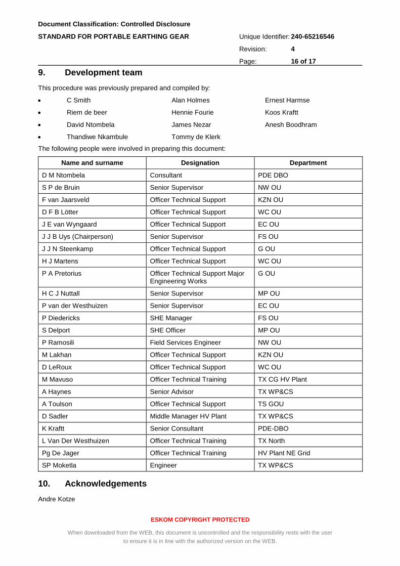
9. Development team
This procedure was previously prepared and compiled by:
C Smith Alan Holmes Ernest Harmse
Riem de beer Hennie Fourie Koos Kraftt
David Ntombela James Nezar Anesh Boodhram
Thandiwe Nkambule Tommy de Klerk
The following people were involved in preparing this document:
Name and surname Designation Department
D M Ntombela Consultant PDE DBO
S P de Bruin Senior Supervisor NW OU
F van Jaarsveld Officer Technical Support KZN OU
D F B Lötter Officer Technical Support WC OU
J E van Wyngaard Officer Technical Support EC OU
J J B Uys (Chairperson) Senior Supervisor FS OU
J J N Steenkamp Officer Technical Support G OU
H J Martens Officer Technical Support WC OU
P A Pretorius Officer Technical Support Major Engineering Works
G OU
H C J Nuttall Senior Supervisor MP OU
P van der Westhuizen Senior Supervisor EC OU
P Diedericks SHE Manager FS OU
S Delport SHE Officer MP OU
P Ramosili Field Services Engineer NW OU
M Lakhan Officer Technical Support KZN OU
D LeRoux Officer Technical Support WC OU
M Mavuso Officer Technical Training TX CG HV Plant
A Haynes Senior Advisor TX WP&CS
A Toulson Officer Technical Support TS GOU
D Sadler Middle Manager HV Plant TX WP&CS
K Kraftt Senior Consultant PDE-DBO
L Van Der Westhuizen Officer Technical Training TX North
Pg De Jager Officer Technical Training HV Plant NE Grid
SP Moketla Engineer TX WP&CS
10. Acknowledgements
Andre Kotze

Document Classification: Controlled Disclosure
STANDARD FOR PORTABLE EARTHING GEAR Unique Identifier: 240-65216546
Revision: 4
Page: 17 of 17
ESKOM COPYRIGHT PROTECTED
When downloaded from the WEB, this document is uncontrolled and the responsibility rests with the user
to ensure it is in line with the authorized version on the WEB.
Annex A – Example of Portable Earth Mat Test Certificate
FORM TITLE Portable Earth Mat Test Certificate
FORM NUMBER 240-65216546 REV DATE February 2022
DOCUMENT TITLE STANDARD FOR PORTABLE EARTHING GEAR
Date Tested
Certificate Expiry Date
Certificate Reference Number
Equipment Class
Rated Voltage
Test Voltage
Type of Test
Temperature at the time of Testing
Humidity at the time of Testing
Atmospheric Pressure at the time of Testing
Serial Number Test Description Test Results
Disclaimer:
General Remarks:
Tested by
Name: Signature: