Embed Size (px)
Citation preview

Designation: C1316 − 08
Standard Test Method forNondestructive Assay of Nuclear Material in Scrap andWaste by Passive-Active Neutron Counting Using 252CfShuffler1
This standard is issued under the fixed designation C1316; the number immediately following the designation indicates the year oforiginal adoption or, in the case of revision, the year of last revision. A number in parentheses indicates the year of last reapproval. Asuperscript epsilon (´) indicates an editorial change since the last revision or reapproval.
1. Scope
1.1 This test method covers the nondestructive assay ofscrap and waste items for U, Pu, or both, using a 252 Cf shuffler.Shuffler measurements have been applied to a variety of matrixmaterials in containers of up to several 100 L. Corrections aremade for the effects of matrix material. Applications of this testmethod include measurements for safeguards, accountability,TRU, and U waste segregation, disposal, and process controlpurposes (1, 2, 3).2
1.1.1 This test method uses passive neutron coincidencecounting (4) to measure the 240Pu-effective mass. It has beenused to assay items with total Pu contents between 0.03 g and1000 g. It could be used to measure other spontaneouslyfissioning isotopes such as Cm and Cf. It specifically describesthe approach used with shift register electronics; however, itcan be adapted to other electronics.
1.1.2 This test method uses neutron irradiation with amoveable Cf source and counting of the delayed neutrons fromthe induced fissions to measure the 235U equivalent fissilemass. It has been used to assay items with 235U contentsbetween 0.1 g and 1000 g. It could be used to assay other fissileand fissionable isotopes.
1.2 This test method requires knowledge of the relativeisotopic composition (See Test Method C1030) of the specialnuclear material to determine the mass of the different elementsfrom the measurable quantities.
1.3 The values stated in SI units are to be regarded asstandard. No other units of measurement are included in thisstandard.
1.4 The techniques described in this test method have beenapplied to materials other than scrap and waste. These otherapplications are not addressed in this test method.
1.5 This standard does not purport to address all of thesafety concerns, if any, associated with its use. It is theresponsibility of the user of this standard to establish appro-priate safety and health practices and determine the applica-bility of regulatory limitations prior to use. Specific precau-tionary statements are given in Section 8.
2. Referenced Documents
2.1 ASTM Standards:3
C1009 Guide for Establishing and Maintaining a QualityAssurance Program for Analytical Laboratories Within theNuclear Industry
C1030 Test Method for Determination of Plutonium IsotopicComposition by Gamma-Ray Spectrometry
C1068 Guide for Qualification of Measurement Methods bya Laboratory Within the Nuclear Industry
C1128 Guide for Preparation of Working Reference Materi-als for Use in Analysis of Nuclear Fuel Cycle Materials
C1133 Test Method for Nondestructive Assay of SpecialNuclear Material in Low-Density Scrap and Waste bySegmented Passive Gamma-Ray Scanning
C1156 Guide for Establishing Calibration for a Measure-ment Method Used to Analyze Nuclear Fuel Cycle Mate-rials
C1207 Test Method for Nondestructive Assay of Plutoniumin Scrap and Waste by Passive Neutron CoincidenceCounting
C1210 Guide for Establishing a Measurement System Qual-ity Control Program for Analytical Chemistry Laborato-ries Within the Nuclear Industry
C1215 Guide for Preparing and Interpreting Precision andBias Statements in Test Method Standards Used in theNuclear Industry
C1490 Guide for the Selection, Training and Qualification ofNondestructive Assay (NDA) Personnel
C1592 Guide for Nondestructive Assay Measurements1 This test method is under the jurisdiction of ASTM Committee C26 on NuclearFuel Cycle and is the direct responsibility of Subcommittee C26.10 on NonDestructive Assay.
Current edition approved June 1, 2008. Published July 2008. Originally approvedin 1995. Last previous edition approved in 2001 as C1316 – 01. DOI: 10.1520/C1316-08.
2 The boldface numbers in parentheses refer to a list of references at the end ofthis test method.
3 For referenced ASTM standards, visit the ASTM website, www.astm.org, orcontact ASTM Customer Service at [email protected]. For Annual Book of ASTMStandards volume information, refer to the standard’s Document Summary page onthe ASTM website.
Copyright © ASTM International, 100 Barr Harbor Drive, PO Box C700, West Conshohocken, PA 19428-2959. United States
1

C1673 Terminology of C26.10 Nondestructive Assay Meth-ods
2.2 ANSI Documents:ANSI 15.20 Guide to Calibrating Nondestructive Assay
Systems4
ANSI N15.36 Nondestructive Assay Measurement Controland Assurance4
3. Terminology
3.1 Definitions—Terms shall be defined in accordance withTerminology C1673.
3.2 Definitions of Terms Specific to This Standard:3.2.1 active mode, n—determines total fissile mass in the
assayed item through neutron interrogation and counting of thedelayed neutrons from induced fissions.
4. Summary of Test Method
4.1 This test method consists of two distinct modes ofoperation: passive and active. The instrument that performs theactive mode measurement is referred to as a shuffler due to thecyclic motion of the 252Cf source. This test method usuallyrelies on passive neutron coincidence counting to determine thePu content of the item, and active neutron irradiation followedby delayed neutron counting to determine the U content.
4.1.1 Passive Neutron Coincidence Counting Mode—Theeven mass isotopes of Pu fission spontaneously. On averageapproximately 2.2 prompt neutrons are emitted per fission. Thenumber of coincident fission neutrons detected by the instru-ment is correlated to the quantity of even mass isotopes of Pu.The total Pu mass is determined from the known isotopic ratiosand the measured quantity of even mass isotopes. This testmethod refers specifically to the shift register coincidencecounting electronics (see (4) and Test Method C1207).
4.1.2 Active Neutron (Shuffler) Mode—Fissionsin 235U, 239Pu and other fissile nuclides can be induced bybombarding them with neutrons. Approximately 1 % of theneutrons emitted per fission are delayed in time, being emittedfrom the fission products over the time range from µs to severalminutes after the fission event. Roberts et. al (5) were the firstto observe delayed neutron emission. We now know that over270 delayed neutron precursors contribute to the yield althoughthe time behavior can be adequately described for mostpurposes using a few (six to eight) effective groups each witha characteristic time constant. The idea of detecting delayedneutrons for the analysis of 235U has been attributed to Echoand Turk (6). The active shuffler mode consists of severalirradiate-count cycles, or shuffles, of the 252Cf neutron sourcebetween the positions illustrated in Fig. 1. 252Cf emits a fissionneutron spectrum. During each shuffle, the 252Cf source ismoved close to the item for a short irradiation, then moved toa shielded position while the delayed neutrons are counted. Thenumber of delayed neutrons detected is correlated with thequantity of fissile and fissionable material. The total U mass isdetermined from the known relative isotopic compostion andthe measured quantity of 235U equivalent (7).
4.2 Either corrections are made for the effects of neutronabsorbers and moderators in the matrix, or a matrix-specificcalibration is used. The effect that needs correction is theincrease or decrease in the specific neutron signal caused by thematrix.
4.3 Corrections are made for deadtime, neutron background,and the Cf source decay.
4.4 The active mode also induces fissions in Pu if it ispresent in the assay item. The passive measurement of Pu canbe used to correct the active measurement of 235U effective forthe presence of Pu.
4.5 Calibrations are generally based on measurements ofwell documented reference materials (8) and may be extendedby calculation (9-11). The method includes measurementcontrol tests to verify reliable and stable performance of theinstrument.
5. Significance and Use
5.1 This test method is used to determine the U and Pucontent of scrap and waste in containers. Active measurementtimes have typically been 100 to 1000 s. Passive measurementtimes have typically been 400 s to several hours. The followinglimits may be further restricted depending upon specificmatrix, calibration material, criticality safety, or countingequipment considerations.
5.1.1 The passive measurement has been applied to benignmatrices in 208 L drums with Pu content ranging from 30 mgto 1 kg.
5.1.2 The active measurement has been applied to wastedrums with 235U content ranging from about 100 mg to 1 kg.
5.2 This test method can be used to demonstrate compliancewith the radioactivity levels specified in safeguards, waste,disposal, and environmental regulations (for example, see NRCregulatory guides 5.11, 5.53, DOE Order 5820.2a, and10CFR61 sections 61.55 and sections 61.56, 40CFR191, andDOE/WIPP-069).
5.3 This test method could be used to detect diversionattempts that use shielding to encapsulate nuclear material.
5.4 The bias of the measurement results is related to theitem size and density, the homogeneity and composition of thematrix, and the quantity and distribution of the nuclear mate-rial. The precision of the measurement results is related to thequantity of nuclear material and the count time of the mea-surement.
5.4.1 For both the matrix-specific and the matrix-correctionapproaches, the method assumes the calibration materialsmatch the items to be measured with respect to the homoge-neity and composition of the matrix, the neutron moderator andabsorber content, and the quantity of nuclear material, to theextent they affect the measurement.
5.4.2 It is recommended that measurements be made onsmall containers of scrap and waste before they are combinedin large containers. Special arrangement may be required toassay small containers to best effect in a large cavity generalpurpose shuffer.
4 Available from American National Standards Institute (ANSI), 25 W. 43rd St.,4th Floor, New York, NY 10036, http://www.ansi.org.
C1316 − 08
2

NOTE 1—The shuffler measurement consists of several cycles. Each cycle includes the movement of the 252Cf source from the storage (or home)position to the irradiation position close to the item, irradiation of the item for a period of about 10 s, return of the source to the shield followed by acounting period of about 10 s. In obvious notation this cycle structure may be succinctly described by the four time periods involved (tin, tirr, tout, tcnt).Typically the one-way transit times are less than 1 s.
FIG. 1 Cf Shuffler Measurement Principle
C1316 − 08
3

5.4.3 It is recommended that measurements be made oncontainers with homogeneous contents. In general, heteroge-neity in the distribution of nuclear material, neutronmoderators, and neutron absorbers has the potential to causebiased results.
5.5 This test method requires that the relative isotopiccompositions of the contributing elements are known.
5.6 This test method assumes that the distribution of thecontributing isotopes is uniform throughout the container whenthe matrix affects neutron transport.
5.7 This test method assumes that lump affects areunimportant—that is to say that large quantities of specialnuclear material are not concentrated in a small portion of thecontainer.
5.8 For best results from the application of this test method,appropriate packaging of the items is required. Suitable train-ing of the personnel who package the scrap and waste prior tomeasurement should be provided (for example, see ANSI15.20, Guide C1009, Guide C1490, and Guide C1068 fortraining guidance). Sometimes site specific conditions andrequirements may have greater bearing.
6. Interferences
6.1 Potential sources of measurement interference includeunexpected nuclear material contributing to the active orpassive neutron signal, self-shielding by lumps of fissilematerial, neutron self-multiplication, excessive quantities ofabsorbers or moderators in the matrix, heterogeneity of thematrix, and the non-uniformity of the nuclear material spatialdistribution especially within a moderating matrix. In general,the greatest potential source of bias for active neutron mea-surement is heterogeneity of the nuclear material within ahighly moderating matrix, while the greatest for passiveneutron measurement is neutron moderation and absorption(12).
6.2 The techniques described in this test method cannotdistinguish which isotope is generating the measured response.If more than one nuclide that produces a response is present,the relative abundances and relative specific responses of thosenuclides must be known.
6.2.1 Active Mode—The unidentified presence of other fis-sionable nuclides will increase the delayed neutron count rate,causing an overestimation of the 235U content. For example, acalibration based on highly enriched U will cause biased resultsif the unknowns actually contain low-enriched U due to thepotential difference in the fractional contribution arising fromthe fast fission in 238U (13, 14).
6.2.2 Passive Mode—The unidentified presence of otherspontaneous fission nuclides, such as Cm and Cf, will increasethe coincident neutron rates, causing an overestimation of thePu content. The active mode measurement of Pu is generallynot sensitive to this source of bias (although counting precisionmay be affected) because the masses of concern are so smalland present a comparatively tiny induced fission signal.
6.3 Lumps of nuclear material can exhibit self-shielding ormultiplication. This effect is often larger for moderating(hydrogenous) matrices.
6.3.1 Active Mode (Self-Shielding)—The nuclear materialon the surface of the lump shields the inside of the lump fromthe interrogating neutrons (15, 16).
6.3.2 Passive Mode (Multiplication)—Neutrons originatingin the lump induce fissions in the same lump which boosts thespecific coincident rate.
6.4 Moderators in the matrix can cause a bias in themeasurement results, unless a correction is made or an appro-priate matrix specific calibration is used. The magnitude anddirection of this bias depend on the quantity of moderatorpresent, the distribution of the fissile material, and the size ofthe item (2, 17).
6.4.1 Although moderation is the greatest potential sourceof bias for passive measurements, the passive method isgenerally less susceptible to the presence of moderator than theactive method.
6.4.2 The presence of absorbers in the matrix can cause biasif there is sufficient moderator present. The moderator slowsfast neutrons which can then be captured more effectively bythe absorbers.
6.4.3 The instrument produces a nonuniform responseacross the container, the severity varying with the concentra-tion of hydrogen in the matrix. A source at the center of thecontainer can produce either a higher or lower response thanthe same source located at the surface of the containerdepending on the item and instrument design.
6.5 Background neutron count rates from cosmic ray-induced spallation can degrade the measurement sensitivity(detection limit) and the measurement precision for smallmasses (18, 19).
6.6 High-background count rates mask the instrument re-sponse to small quantities of special nuclear material for boththe active and passive modes (20-22).
6.7 High gamma dose rates eminating from the item (>10mSv h–1 of penetrating radiation) may cause pile-up andbreak-down in the 3He-filled proportional neutron detectors(23). Care should be taken to ensure the item is within theacceptable range of the instrument.
6.8 Certain other elements may produce delayed neutronsfollowing (fast) neutron irradiation (24).
7. Apparatus
7.1 The apparatus used in this test method can be obtainedcommercially. Specific applications may require customizeddesigns to cope with (for example) container sizes, containerweights, activity levels, integration into the facility (23, 25-28).The following description is one possible design. Fig. 2 is acutaway illustration of a shuffler to measure 208 L drums. Inthis design, the 252Cf source storage shield is positioned on topof the measurement chamber. This design weighs approxi-mately 8000 kg, and is 3 m high and 2 m in diameter.
7.2 Counting Assembly—see Fig. 3.7.2.1 The neutron detectors are 3He-filled cylindrical pro-
portional counters embedded in polyethylene, located aroundthe item in a near 4π geometry. The detection efficiency forneutrons of fission energy should be above about 15 %. Larger
C1316 − 08
4

detection efficiencies generally provide better precision andlower detection limits for a given count time subject to cycletime, source coupling and other operational parameters. Thecounter detection efficiency should vary less than 10 % overthe item volume with no item present.
7.2.2 The flux monitors are 3He-filled proportional countersmounted on the inner walls of the measurement chamber andnot embedded in polyethylene. One flux monitor is coveredwith Cd approximately 1 mm thick; the other is bare andresponds predominantly to thermal neutrons. The Cd shieldsthe so-called fast flux monitor from thermal neutrons;therefore, the two flux monitors can be compared in order toprovide information about the neutron energy distributionemerging from the item when the Cf shuffler is brought up.Measured matrix corrections are functions of the fast andthermal flux monitor rates.
7.3 Shielding—The quantity of radiation shielding forthe 252Cf source is governed by personnel safety requirementsalthough control of the background is also a consideration.
7.3.1 The measurement chamber is typically surrounded by0.3 to 0.6 m of materials such as polyethylene and boratedpolyethylene to shield the operator during the 252Cf irradiation.
7.3.2 The shield for the 252Cf storage position is typicallyabout 0.6 m thick (1.2-m cube), depending on the sourcestrength, or the source is placed 1.8 m underground. Compositeshields are more effective than polyethylene alone forlarge 252Cf sources (29). The source home position may have aheavy-metal shield to reduce direct gamma dose. The compos-ite shield concept should also takes into account secondarycapture gamma-ray generation. If the source store is notdirectly mated to the measurement chamber, care should be
taken in the routing of and shielding to the intervening guidetube so as to manage the time averaged dose rate in the vicinity.
7.4 Electronics—High count rate, commercially availablenuclear electronics provide standard logic pulses from the 3He-filled proportional counters. These pulses are typically pro-cessed by shift register coincidence electronics for the passivemeasurement, and by gated fast scalers or a multi-channelscaling system for the active measurement. Other correlatedneutron counting electronics can be used, with appropriatechanges to the data reduction equations.
7.5 252Cf Source Drive System—The source is attached to aflexible drive cable that runs inside a guide tube. The sourcemovement is controlled by stepping motors or an alternativemethod that offers precise timing, positioning, and computercontrol. During the active measurement, variations in the
NOTE 1—A sketch of a shuffler designed to assay 208-L drums. Thesource storage shield is a 2000-kg, 1.2-m cube that resides close to themeasurement chamber. In this design it is on top of the measurementchamber. This configuration reduces the footprint of the instrument andmay reduce the cosmic ray induced background somewhat. Other con-figurations are also in common use. The stepping motor drives the Cfsource through the source transfer (or guide) tube between the storageposition and the irradiation position inside the measurement chamber.
FIG. 2 Shuffler for 208-L Drums of Waste
NOTE 1—The front and top views of the measurement chamber shownin Fig. 2 are shown here in greater detail. The 208 L drum sits on a rotatingplatform above the bottom detector bank. Six side banks surround theitem, with the Cf source transfer tube at the back. The two flux monitorsare placed at the rear of the item chamber.
FIG. 3 Shuffler Detector Bank Diagram
C1316 − 08
5

timing of the source transit, irradiation or counting portions ofthe shuffles cause variations in the measured response. Com-ponents should be selected to reduce this potential problem tonegligible levels.
7.6 252Cf sources are commercially available and are usu-ally replaced every few years (typically of the order of twohalf-lifes) subject to preserving desired active detection limitsand precisions. The vendor should understand the safety issuesand provide guidance in addressing them.
7.6.1 The source vendor should encapsulate the 252Cf, se-curely attach the source drive cable, provide shielded shippingcasks, and assist with the source installation and disposal.
7.6.2 The source vendor should be requested to providedocumentation for the ruggedness and integrity of the sourceencapsulation and perform swipes to demonstrate that theoutside of the source capsule is not contaminated.
7.7 Data acquisition and reduction, control of the sourcemotion, and the diagnostic tests require interfacing the instru-ment to a computer as illustrated in Fig. 4. The computer andsoftware normally are provided by the instrument vendor.
7.8 Customized Design Issues:7.8.1 An initial 252Cf source size of 550 µg is generally
adequate for measurements of 208 L drums. Performance for agiven source strength can be tailored to some considerableextent by adjusting the chamber design—in particular detectionefficiency and source coupling play important roles.
7.8.2 It is recommended that the size of the measurementchamber be just slightly larger than the size of the items to bemeasured. If small items require measurement in a largemeasurement chamber, the items should generally be centeredin the chamber. Coupling of the interrogation source to the itemand of the item to the flux monitors may need specialconsideration and a container specific calibration will generallybe needed.
7.8.3 During an active measurement of a large item, theitem should be rotated and the Cf source should scan thevertical length of the item. Some designs use continuousrotation and scanning motion (2) while others acquire datausing a series of discrete angular and source positions (21, 27,28). Discrete scans can provide input for optional analysisalgorithms (such as might provide coarse spatial corrections) ormight be useful where a symmetric pattern of 3He proportionalcounters can not be used (for example if the instrument isconstrained by the interface to a hot cell).
7.8.4 The standard shuffler configuration assumes somehydrogenous and some metallic matrices will be measured.The interrogation-neutron energies are therefore kept high bynot using spectrum tailoring materials between the Cf sourceand the item being measured and by using a steel reflectorbehind the Cf source (1, 2). This configuration also includeslining the assay chamber with Cd, which prevents neutrons thatare thermalized in the polyethylene of the detector banks fromentering the measurement chamber. Thermal neutrons gener-ally penetrate less deeply into the matrix and consequentlyspatial uncertainties will generally be higher if the matrix andspecial nuclear material distribution are not homogeneous.Thermal neutrons also are less pentrating into aggregates of
special nuclear material. The down side of using a Cd liner,however, is that the sensitivity be over an order of magnitudepoorer. The prospects and potential benefits of spectrumtailoring are discussed in (30). It should also be noted thatsome containers (for example, those with concrete liner orknown to possess a particular waste characteristics) and somechambers (for example, those requiring significant Pb shieldingto control the gamma-ray does rate on the 3He proportionalcounters) introduce neutron transport peculiarities that shouldbe considered as an integral part of the design process (21, 26,27).
7.8.4.1 When it is assured that (a) lumps are not a signifi-cant problem and (b) the matrix is a weak moderator, apolyethylene sleeve can be placed around the assay item for theactive mode measurement to reduce the energies of theinterrogating neutrons, enhancing the fission rate, the
NOTE 1—The electrical components and their connections are indi-cated. The Cf source is moved by the stepping motor and associateddriver. Three source sensors are used to verify the source position. Thedetector signals are amplified and discriminated in junction boxes intowhich the 3He-filled cylindrical proportional counters are fastened. Thelogic outputs of the discriminators are fed to scalers and a coincidencecounting module. The computer controls the source and rotator andreceives the results from the scalers and coincidence counter according tothe strict timing sequence in use.
FIG. 4 Shuffler Electronic Controls Diagram
C1316 − 08
6

precision, and the sensitivity. A different calibration is neces-sary for polyethylene “sleeve” measurements. An alternativescheme is to make the Cd liner removable to achieve the sameobjective (30).
8. Hazards
8.1 Safety Hazards—Consult qualified professionals asneeded.
8.1.1 Take precautions to maintain personnel radiation ex-posures as low as reasonably achievable (ALARA). See alsoGuide C1592. Typical doses at the surface of the instrument are<20 µSv h–1.
8.1.1.1 The radiation dose from 550 µg 252Cf (unshielded) isabout 10 mSv h–1 at 1 m, consisting of both gamma andneutron radiation. Large 252Cf sources require remotehandling, shielding, and interlocks on automatic transfermechanisms to help prevent inadvertent or excessive exposure.
8.1.1.2 For large source shields, the gamma rays resultingfrom neutron capture in hydrogen can contribute significantlyto the dose on the outside of the shield; shields loaded with Bor Li can greatly reduce this effect.
8.1.2 Take precautions to prevent inhalation, ingestion, orthe spread of radioactive contamination. Periodic alpha moni-toring of calibration materials, measurement control items, andscrap and waste containers to verify their integrity is recom-mended. Periodic inspection and monitoring of the shufflersource and guide tube should be carried out.
8.1.3 Take precautions regarding nuclear criticality, espe-cially of unknown items. The measurement chamber approxi-mates a reflecting geometry for fast neutrons. Do not assumethat waste is not of criticality concern.
8.1.4 Take precautions to prevent inhalation, ingestion, orthe spread of Cd and Pb, if used as shielding. They should becovered with nontoxic materials.
8.1.5 Take precautions to avoid contact with high voltage.The proportional counters require low current supplies ofapproximately 2 kV.
8.2 The results of this test method might be used to makedecisions regarding, for example, the handling and disposal ofitems or the cessation of safeguards on the items. Consultqualified professionals and Guide C1490 as needed.
9. Initial Preparation of Apparatus
9.1 The initial preparation of the shuffler passive/activeneutron (PAN) apparatus is outlined in 9.2 through 9.6, whichdiscuss the initial setup, calibration, and the initialization ofmeasurement control. The details of preparation are site-specific, dependent on the material categories to be measured,and are generally performed by experts (31).
9.2 Initial Setup:9.2.1 The apparatus weight exceeds typical industrial floor
load capacities. Check for adequate floor load capacity beforeinstallation.
9.2.2 Locate the apparatus to minimize radiation exposureto the operator from scrap and waste items. The shuffler’sshielding typically screens the measurement chamber frommost sources of background although ultimately detectionlimits are governed by background conditions (18, 20).
9.2.3 Perform the initial setup recommended by the systemmanufacturer, obtaining assistance as needed.
9.2.3.1 Most electronics settings are optimized by themanufacturer, and changing them may affect the instrument’sperformance.
9.2.3.2 The initial setup might include verifying or testingthe following items: (a) that all software is loaded and running;(b) the safety features for the Cf source drive mechanism; (c)the operation of the source drive mechanism; (d) the statuslamps; (e) the deadtime coefficients and the coincidence gatelength; (f) the rotation motor; (g) the Cf source transfervelocity, acceleration, and scanning parameters; (h) the parallelport inputs and outputs; and (i) testing the neutron detectionelectronics with background and with small sources.
9.3 Calibration: Preparation—Use this test method with ascrap and waste management plan that segregates materialswith respect to their neutron moderation and absorption prop-erties. References (2) and (32) describe calibration exercisesand provide illustrative data. The passive calibration is con-ventional (see C1207) and 252Cf may be used as a surrogatefor
240
Pueff (33). Additional sources of information can befound in Guides C1009, C1068, C1128, C1156, C1210, andC1215; ANSI Guide 15.20; NRC Guides 5.11 and 5.53; DOEOrder 435.1; and U.S. Regulations 10CFR61 and 40CFR141.
9.3.1 Determine the different material types that representthe scrap or waste streams to be measured.
9.3.2 Prepare and characterize the calibration materials.They should represent the material types with respect toparameters that affect the measurement, such as moderationand absorption. The calibration materials should span thespecial nuclear material mass ranges expected in the scrap orwaste to be measured. The fabrication should documenttraceability for the special nuclear material parameters.
9.3.3 Record the calibration procedure and data. The datashould demonstrate the variation of the volume weightedaverage instrument response as a function of the nuclearmaterial mass and the matrix.
9.3.4 The volume weighted average (VWA) response is anestimate of the count rate that would be obtained from a itemcontaining a homogeneous matrix with a uniform distributionof special nuclear material. One possible way of estimating theVWA response (2, 34) is a weighted average calculated from aseries of measurements. One or more physically small capsulesof special nuclear material of known and ideally low self-shielding are placed in containers filled with uncontaminatedmatrix material to estimate the response of the instrument todifferent matrices. Placement is typically along tubes whichrun the length of the containers and are placed in the matrix atthe areal center of equal area columns. For 208 L drumstypically 3 to 5 radial positions and 5 to 7 axial positions wouldbe used to define the centroids of the voxels, depending on theseverity of the matrix, which defines the spatial gradients. TheVWA of the measured response map is computed along withthe corresponding standard deviation which is indicative of thepotential bias from measurements made with nonuniform(single point-like) distributions of special nuclear material.Spatial mapping using encapsulated sources is also often apragmatic way to decrease the cost of generating a broad range
C1316 − 08
7

calibration compared to characterizing and storing suitabledistributed calibration materials for large sets of diversematrices. Spatial maps also lend themselves to numericalspatial integration schemes. Monte Carlo simulations bench-marked to a reference measurement may also be used togenerate VWA responses using basic knowledge of the neutrontransport properties along with knowledge of the matrixcompositions (for example, the measured response at only asingle position within a test matrix can be scaled by thecalculated VWA-to-point ratio). In this way fewer experimen-tal points are needed which can accelerate the calibrationprocess. As a general rule however, measurements across a setof test matrices should be made and this is especially useful inestablishing flux monitor (or Add-A-Source) trends with matrixcharacteristics which are more difficult to model accurately.
9.4 Calibration: Response vs. Mass—This calibration deter-mines the relationship between the measured instrument re-sponse and the mass of nuclear material. If the matrix-specificcalibration approach is being used, this calibration data isobtained using the specific matrix found in the unknowns (32).Otherwise, a benign matrix is used. The flux monitor data maybe recorded for later use in assessing whether the correctmatrix-specific calibration is being used. If the polyethylenesleeve is used for measurements of a certain material category,then the calibration data must be acquired with it also (2, 32,35).
9.4.1 active mode—relates the delayed neutron count rate tothe effective or equivalent 235U mass (7).
9.4.2 passive mode—relates the coincident neutron countrate to the effective mass of 240Pu (7).
9.4.3 Determine the range of the calibration. This is oftendefined by the smallest and largest masses used in the calibra-tion.
9.4.3.1 The best fit to the calibration function within thecalibration range sometimes yields nonsensical results outsideof the calibration range. Any use of the instrument outside ofthe calibration range should be evaluated carefully.
9.4.3.2 If the calibration is extended to very small masses,the range should begin at zero instead of the lowest mass usedin the calibration. The user should evaluate the response of theinstrument with matrix items that contain no special nuclearmaterial.
9.4.4 Measure each calibration mass such that the measure-ment precision is better than that expected for assay items ofsimilar mass by using longer count times or replicate counts.
9.4.4.1 Measurements of small mass items can have largeuncertainties due to lack of signal. If the measurement preci-sion is 10 % or worse, such measurements might be moreuseful to check the calibration rather than determine it.
9.4.5 Analyze the calibration data to determine an appropri-ate function. The choice of calibration function will depend onthe characteristics of the material categories and the calibrationmass range (1, 2, 29, 32, 36-43).
9.4.5.1 Calibration data for waste measurements with smallamounts of special nuclear material can generally be fitted witha linear function.
9.4.5.2 If the calibration is extended to very small masses,the calibration might produce less bias if the fit is forced
through the origin. The user should verify the appropriatenessof this with measurements of matrix material without specialnuclear material present.
9.4.5.3 Calibration data for scrap measurements of highmass items may not be suitable for fitting with a linearfunction.
9.5 Determining the Matrix Correction—This section is notapplicable if the matrix-specific calibration is being used. Itdescribes a procedure that determines the relationship betweenthe measured flux monitor response and the neutron modera-tion and absorption effects of the matrix on the measured countrate for uniform items. This relationship will determine acorrection to the count rate data that is made before thecalibration described in 9.4 is used. Different corrections arerequired for the active and passive modes.
9.5.1 Determine the range of matrix correction for the activeand passive modes separately.
9.5.1.1 At some point, the moderator and absorber contentwill be sufficiently large as to shield the innermost locations inthe item. The user should not try to make a correction for thismeasurement situation, where special nuclear material could bein the item but not respond.
9.5.1.2 The user must choose how large a response variationwith position is acceptable to meet the measurement objec-tives. A hydrogen density of 0.03 g mL–1 will yield amaximum-to-minimum response variation of approximately2.4 for 208-L drums (2).
9.5.2 Measure the flux monitor responses and the countrates from the source for each matrix. The measurementprecisions should be smaller than those typically obtained inmeasurements of unknowns or small enough to make anacceptable contribution to the overall measurement error.
9.5.3 Demonstrate that the flux monitor response is ad-equately independent of the special nuclear material sourcesize and location in the item.
9.5.4 Analyze the data to determine a suitable flux monitorcorrection function. The choice of correction function willdepend on the characteristics of the material categories. Sev-eral functions have been used to perform an empirical fit to thistype of data (2, 12, 17, 29, 38).
9.5.4.1 The corrected data in Fig. 5 for passive and Fig. 6for active measurements of homogenous distributions of 235U,shown only as an example, both used the following empiricalfunctional form (2):
CF 5 1/Rp~R!, where the exponent p~R! 5 a1 R21a2 R1a3 (1)
where:CF = the rate correction factor. In Section 11 we
use subscripts a and p to indicate the activeand passive correction factors respectively,
R = bare-to-Cd-covered flux monitor responseratio,
a1, a2 and a3 = fitted coefficients specific to the mode (pas-sive or active) and instrument.
9.5.5 An alternative approach is the matrix-specificcalibration, where the user attempts to match the matrix effectsof the unknown items with the calibration items (32). This
C1316 − 08
8

approach might use the flux monitor data to verify that thecalibration and item matrices are suitably matched.
9.6 Initialize Measurement Control—The need for adjust-ment of the instrument can be determined by measurementcontrol procedures (44) (ANSI N15.36). These proceduresmake use of background measurements, replicate measure-ments of a specific item, and periodic remeasurement of certainitems.
9.6.1 Determine the measurement control item responsesand their uncertainties. These values are the ones to whichfuture measurements will be compared (see 10.1).
9.6.2 Items used in measurement control must provideconsistent measured values within statistical expectations eachtime they are measured. Perform corrections for radioactivedecay when necessary.
9.6.3 Documentation of the measurement control of theinstrument may be required (that is, DOE Order 474.1).
9.6.4 The choice of control limits and the action requiredafter a “failure” should take into consideration the measure-ment uncertainties and the probability of a false positive (44).
10. Procedure
10.1 After calibration, the procedure consists of measure-ments of items with unknown special nuclear material contentand measurements that demonstrate that the apparatus iscalibrated and functioning properly (measurement control).
10.2 Measurement Control—Measurement control measure-ments are made before assays of unknowns and are inter-spersed between measurements of unknowns to verify properfunctioning of the instrument. If the measurement controlindicates the instrument response has changed, determine thecause and make the necessary repairs. In addition, all measure-ments of unknowns since the last successful test are suspectand may need to be repeated.
10.2.1 Background Measurements—Perform periodic back-ground measurements (44).
10.2.1.1 Passive Mode—Traditional practice is to performthese measurements daily with no special nuclear material inthe assay chamber. Low total neutron count rates verify that nobreakdown of the proportional counters or their electronics hasoccurred. Count rates of zero suggest the detector high voltageis off, part of the detection electronics is nonfunctional, or thedetector electronics are disconnected. This background mea-surement is generally used in the passive calculations.
10.2.1.2 Active Mode—A background measurement is madeat the start of each assay while the item is in the assay chamber,before the source shuffles begin. For a combined PAN assay theactive background is usually the non-deadtime corrected pas-sive data.
10.2.2 Measurement Control Bias Measurement—Performperiodic measurements of stable items containing specialnuclear material to verify the stability of the instrumentresponse (44). Typically high and low masses are used ondifferent days. Traditional practice is to perform a dailymeasurement for instruments used daily although more fre-quent state of health checks may be made subject to anapplication specific consequence analysis. For instrumentsused intermittently, this check is recommended before and aftereach use. Agreement with the previous value within the controllimits indicates long-term stability of the instrument’s re-sponse. Long-term stability suggests that the calibration is stillvalid. Low results may indicate that a detector or detector bankis not functioning correctly. High results may indicate electri-cal noise.
NOTE 1—The measured active response per gram of 235U in 208-Ldrums is shown for 20 matrices. Both the uncorrected response (+) and theflux monitor corrected response (x) are plotted. The relative standarddeviation of the corrected responses is 14 %. The matrices span a widerange of characteristics typical of those found in facilities (2). The largesthydrogen content in a matrix was 9.65 kg; the largest boron content was0.20 kg.
FIG. 5 Active Response as a Function of Flux Monitor Ratio
NOTE 1—The measured passive response per gram of 240Pueff in 208-Ldrums is shown for 18 matrices. Both the uncorrected response (+) and theflux monitor corrected response (x) are plotted. The relative standarddeviation of the corrected responses is 12 %. The matrices cover a widerange of characteristics typical of those found in facilities (2). The largesthydrogen content in a matrix was 9.65 kg; the largest boron content was0.20 kg.
FIG. 6 Passive Response as a Function of Flux Monitor Ratio
C1316 − 08
9

10.2.2.1 The measurement control item used for the checkmust provide a consistent response. Corrections should bemade for radioactive decay.
10.2.2.2 The uncertainty estimated from counting statisticsfor these measurements will be constant for a given count time,except for changes due to source decay. Otherwise, the sourceof variation should be investigated.
10.2.3 Measurement Control Precision Measurement—Perform periodic replicate counts of different items to verifythe estimates of the measurement precision (44). This testmight be conducted monthly or after each calibration. Statis-tical agreement between the standard deviation of the replicatesand the uncertainty estimate from a single measurement’scounting statistics indicates short-term stability of the instru-ment’s response. Lack of agreement might indicate back-ground variations, electrical instabilities, mechanical changes,or errors in the implementation of the software algorithms.
10.3 Item Measurements:10.3.1 Position the item to be measured in the counting
chamber. The counting geometry should be the same for allmeasurements. If the polyethylene sleeve is used for assay ofan item then the calibration used for the analysis should havebeen obtained in the “sleeve” configuration.
10.3.2 Measure for the chosen count times. It is oftenadvisable to measure unknowns and measurement controlitems for the same count times so as to eliminate this as apotential source of error.
10.3.2.1 Passive Mode— The passive count time is typicallybetween 400 and 1000 s. When a matrix correction is desired,the passive count is followed by a short count (on the order of10 to 100 s) with the 252Cf source interrogating the item inorder to gather the necessary flux monitor rates. Additionaluseful information might also be obtained at this time (seeSection 10.3.4.3). The drum may be rotated an integral numberof times during the flux monitor determination. Other experi-mental passive matrix correction techniques may optionally beincorporated and used (for example, the Add-A-Source method(36)).
10.3.2.2 Active Mode—For a shuffler of the type illustratedin Fig. 3 and Fig. 4 the item is usually rotated during the activemeasurement, asynchronously with the 252Cf source motion.The active count (for a total assay sequence of about 1000 s)generally consists of a 250-s background count of the item withthe shuffler source stored, followed by approximately 30shuffles of the 252Cf source, each with an interrogation of about10 s and a delayed neutron count time of about 10 s. One-waysource transit times are less than about 1 s. The cumulativedelayed neutron counting period would be 30 × 10 = 300 s inthis example.
10.3.3 When the counts are complete, document the mea-sured quantities.
10.3.3.1 Passive Mode—Compute the deadtime and back-ground corrected totals, reals and flux monitor rates along withtheir associated precison. (See Test Method C1207 for addi-tional details on coincidence counting).
10.3.3.2 Active Mode—Compute the deadtime and back-ground corrected delayed neutron rate.
10.3.4 The following diagnostic tests are recommended foreach measurement.
10.3.4.1 Passive Mode—(a) The total neutron count rate canbe used to estimate the accidentals rate (4, 41). Lack ofagreement within statistical uncertainties between the esti-mated and measured accidentals count rates suggests a hard-ware failure in the coincidence circuitry or that the backgroundneutron count rate changed significantly during the measure-ment. Note that for a symmetric counter and fairly homoge-neous items the passive rate should remain approximatelyconstant as the item is rotated. For some designs, however, theitem must be held fixed during data acquisition and indexed toobtain a rotational average for this test to pass. (b) Eachmeasurement can be divided into several short countingperiods, and statistical tests performed looking for outliers inthe individual counting periods (12, 36, 41, 45, 46). This“outlier” test reduces the effects of cosmic ray background orof changing conditions during the measurement. Outliers aregenerally replaced with data from an additional countingperiod, which is obtained without operator intervention by thesoftware.
10.3.4.2 Active Mode—(a) A detector bank with zero countsis suspect and reported with an error message (1,2). This errorcondition might indicate the detector bank is not functional. Ifbackgrounds are very low in every detector bank, this diag-nostic might be more confusing than helpful; (b) Ratios ofcounts in different detector banks can be compared withhistorical values; if a ratio is statistically out of bounds, anerror message can be generated (1,2). This error conditionmight indicate that either a detector bank is not functioningcorrectly or the assay item is not suitable for measurement. Forlow count rates, the value of this diagnostic is also low; (c) Theoverall regularity of the various phases of an assay can bechecked by calculating a quantity (1,2) from the measuredtimes for motion of the 252Cf source and the count times. Thisquantity is compared to the value calculated using the nominaltimes for motion and counting. If the two values differ by morethan expected, a hardware failure in the source motion con-troller or the clock might be suspected.
10.3.4.3 Active Mode—The neutron transmission throughthe item has been used to evaluate whether the item behavessimilarly to the calibration items (32). During an irradiationwith the 252Cf source, compare the measured count rate in theopposing detector banks with the rates obtained with thecalibration items. A statistically significant difference suggeststhat the wrong calibration is being used. A very low valuesuggests that inadequate penetration of the item has occurred,the measurement is not sensitive to the center of the item, andthe potential exists for undetected nuclear material to be in thecenter of the item. It is possible to use the flux monitor countrates in a similar manner (2).
10.3.5 Calculate the amount of special nuclear material (forexample, U, Pu or both) in the item.
10.3.6 If replicate measurements are performed, wait atleast four minutes after the 252Cf irradiation ends beforestarting the next assay to allow the induced delayed neutronsignal to decay to negligible levels.
10.3.7 Remove the item from the counting chamber.
C1316 − 08
10

11. Calculations
11.1 This section provides a summary of the calculationsdeveloped for a 208-L system. Use of other electronics mayrequire different equations. The calculations are usually per-formed by the software, not by the user. The vendor shouldprovide quality assurance that the calculations are correctlyimplemented in the software. The calculations follow the samegeneral approach whether the results are used for calibration,measurement control, or determining an unknown. Estimatesof the measurement uncertainties follow standard propagationtechniques and are detailed in the references.
11.2 Passive Assay for Plutonium—Data reduction for thepassive coincidence measurement is explained in Test MethodC1207 and (2, 4, 41, 46). Most of the variables were defined in10.2.3.
11.2.1 Determine the total neutron count rate and its randomstatistical uncertainty.
11.2.2 Determine the coincidence count rate and its randomstatistical uncertainty. There are approximations for statisticaluncertainty (see (4, 12) and Test Method C1207) which use thecumulative shift register results, however, if the count has beenbroken into a series of shorter interval the scatter in the datacan be used directly.
11.2.3 Correct the count rates, including those for the fluxmonitors, for deadtime (4, 29).
11.2.4 Perform a background subtraction.11.2.5 Matrix Correction:11.2.5.1 If the matrix correction calibration is being used,
make a correction to the deadtime and background correctedreals rate for matrix effects using the flux monitor responses(1,2, 12, 36) obtained during the 252Cf interrogation.
Rc 5 R" 3 CFp~flux monitor! (2)
where:the passive flux monitor correction, CFp (flux-monitor), isdiscussed in 9.4 and (2).
11.2.5.2 If the matrix-specific calibration approach is beingused, no matrix correction is made.
11.2.6 As the assay gets larger, effects that have the poten-tial to cause bias, like multiplication, become more important,if not corrected (4, 41, 42, 46).
11.2.7 Use the calibration function, the parameters de-scribed in 9.3, and Rc to calculate the assay result in terms ofthe 240Pueff mass, meff. The 240 Pueff mass is defined in terms ofthe masses, mA, of the Pu isotopes, A, as:
meff 5 2.52 m2381m24011.68 m 242 (3)where the numerical weighting factors are nominal nucleardata values. From time to time revised nuclear data evalua-tions become available and the coefficients may also beslightly dependent on chamber design. For many situa-tions, 238Pu and 242Pu are minor contributors and the resultsare insensitive to the exact values provided the same valuesare used for calibration and for the analysis of the assay ofunknown items.
11.2.7.1 Waste measurement data are generally suitable fordirect proportionality between Rc and meff.
11.2.7.2 Scrap measurement data might require a generalquadratic function (41, 42, 46):
Rc 5 k01k1 meff1k2 ~meff!2 (4)
where:k0, k1, and k2 are the calibration constants determined in 9.3.
11.2.7.3 Other methods of data analysis are available thattake advantage of additional information when it is available(4, 41, 42, 46).
11.2.8 Use the isotopic ratios and meff to calculate the assayresult in terms of total Pu:
massPu 5 meff/~2.52 f2381f 24011.68 f242! (5)
where:fA = the weight fraction of Pu isotope A.
11.2.9 The estimate of the measurement uncertainty shouldinclude the components that cause significant effects. Thesegenerally include counting statistics, calibration errors, uncer-tainties in the matrix correction factor, and uncertainties in theisotopic ratios. Some components may be difficult to quantify.
11.3 Active Assay for Uranium—Data reduction for theactive shuffler measurement is explained in (1, 2). Most of thevariables were defined in 10.2.3.
11.3.1 The uncorrected delayed neutron count rate, ucr, iscomputed from the total counts and time.
ucr 5 T1/t1 (6)
where:T 1 = total neutron counts acquired over the n shuffles, and
t 1 = total counting time for the shuffles evaluated from theproduct of the number of cycles and the delayedneutron counting period per cycle.
It is assumed that the same number of shuffles and the sametime pattern are used for unknowns and calibrationmeasurements, otherwise, make the necessary corrections (1,47).
11.3.2 Subtract the background count rate, derived from thetotal active background counts, bkgd, accumulated:
ucr' 5 ucr 2 ~bkgd/t2! (7)
where:t 2 = background time.
11.3.3 Make a correction for the radioactive decay of theinterrogation source, allowing for the isotopic composition ofthe Cf in the source if necessary:
ucr" 5 ucr' 3 exp~λt '! (8)
where:λ = the effective decay constant, andtʹ = the time since the reference date of the calibration.
11.3.4 Use the same count times, source transfer timing, andnumber of shuffles for each measurement, or correct for thedifferences (1).
11.3.5 Use the flux monitor matrix correction factor tocorrect the delayed neutron signal for matrix effects (1, 2, 29).
ccr 5 ucr" 3 CFa~flux monitor! (9)
where:CFa(flux monitor) is discussed in 9.4 and (2).
C1316 − 08
11

11.3.5.1 If only one matrix is being assayed and the appro-priate calibration materials were used for it, the user might usethe matrix-specific calibration instead of applying the matrixcorrection factor.
11.3.6 No corrections are made for self-shielding and het-erogeneity (1,2).
11.3.7 Use the calibration function and parameters to com-pute the assay result in terms of 235U mass from the correctedmeasured response, ccr.
11.3.7.1 Waste measurements involving U of a single en-richment generally use a linear function:
ccr 5 k 235 m235 (10)
where:k235 = calibration constant for 235U, andm235 = mass of 235U.
11.3.7.2 If a wide range of U enrichment is to be measured,or if Pu was found in the passive assay, then additionalcorrections may be required (1,2, 29).
11.3.8 Use isotopic information and the 235 U mass to getthe assay result in terms of U mass.
muranium 5m235
f235
(11)
where:f 235 = weight fraction of 235U.
11.3.9 The estimate of the measurement uncertainty shouldinclude the components that cause significant effects. Thesegenerally include counting statistics, calibration errors, uncer-tainties in the matrix correction factor and uncertainties in theisotopic ratios. Other components may be difficult to quantify.
12. Precision and Bias
12.1 The precision and bias of shuffler measurements arefunctions of several interrelated factors, consequently a simpleprecision or bias statement is not possible (2, 34, 35). Theinterrelated factors include facility-specific procedures,matrices, chemical forms, and quantities. This section providesinformation but cannot substitute for critical thinking, profes-sional skill, and verification measurements. The evaluation ofthe uncertainty for a shuffler assay is not a purely mathematicaltask, it requires detailed knowledge of the measurementmethod, the procedures, and the items being measured. Theevaluation should be documented as part of the total measure-ment uncertainty assessment and reviewed by an NDA profes-sion as defined in Guide C1490 prior to the instrument enteringoperation. Measurements of uncharacterized drums generallyyield results of indeterminate accuracy. However, a combina-tion of measurement methods applied to such drums may beused to estimate measurement uncertainties. Except for mea-surements of small quantities of nuclear material, the possibil-ity of bias is of greater concern than the issue of inadequateprecision (2, 35). This section lists precision and bias state-ments applicable to both passive and active measurements,then statements specific to the passive mode, then statementsspecific to the active mode.
12.2 Passive and Active Measurements—Each user of thistest method should estimate the precision and bias for eachscrap and waste category. See (2, 29, 32, 35, 40) as examples.
12.2.1 A comparison with another assay technique can behelpful to estimate potential bias. Figs. 7-9 are examples ofsuch comparisons. In general, other techniques (for example,Test Method C1133 or Test Method C1207) are susceptible todifferent sources or magnitudes of bias.
12.2.2 Calibration exercises can be helpful to estimatepotential bias (2). In general, it may be difficult to determinehow well the calibration matrices emulate the unknowns.
12.2.3 Destructive analysis is generally not practical as asource of bias information when the items are heterogeneous.
12.3 The precision of a shuffler measurement can be esti-mated using statistical calculations on the data from a singlemeasurement or it can be evaluated by replicate measurements.
12.3.1 Longer counting times (that is, a greater number ofshuffler cycles in active mode), more nuclear material, or theuse of an apparatus with higher detection efficiency willimprove the measurement precision. In general, wherethroughput and other factors are driving considerations, the
NOTE 1—The results of active shuffler measurements for the 235 Ucontent of 208-L drums are compared to the results of segmented gammascanner (SGS) measurements (32, 35). These drums contain low-densitywaste with unknown U loadings from an enrichment plant located inPortsmouth, Ohio. The matrices are alumina, low-density combustiblewaste, ABSORBAL, and oil-soaked 3M cloth. The SGS results are froma direct measurement of the drum (if the transmission at 186 keV waspossible) or from summing the results of measurements on 127 mm (5-in.)cans whose contents were poured into the drums. The measurementuncertainties for both techniques in this example are dominated by biasrather than precision. The lack of agreement below about 9 g suggestsadditional information (another measurement technique perhaps) isneeded if a better understanding of the bias is desired.FIG. 7 Comparison Between Active Mode and Segmented Gamma
Scanner Results from an Enrichment Facility
C1316 − 08
12

counting sequence is chosen to make best use of the assay timeavailable given based on what is known about the measurementscenario.
12.4 The bias of a shuffler assay is dependent upon manyfactors relating to the segregation and packaging of the matrixmaterials as well as the physical and chemical properties of thenuclear material. If the criteria of 5.4 and 9.2 are not met, thebias is indeterminate.
12.4.1 Biases can occur if the characteristics of the calibra-tion materials differ significantly from those of the item beingmeasured.
12.4.2 Mixing material from different matrix segregationcategories can lead to a situation where no calibration isappropriate.
12.5 Moderators and absorbers in the matrix can cause biaseffects. Over some range these effects can often be adequatelycorrected; large quantities, however, may bias the result high orlow (2).
12.5.1 Hydrogen is the element with the largest potential forcausing a bias due to moderation and absorption effects.
Reference (2) describes a method to determine correctionsvalid for hydrogen levels up to 0.04 g mL–1.
12.6 Bias effects can occur as a result of varying fill heights,heterogeneity, or item positioning because the detection effi-ciency is not constant over the assay volume. Spatial effects forthe detection efficiency vary as much as 10 % for the totals anddelayed neutron count rates, and as much as 19 % for thecoincidence count rate over the volume of the assay chamberfor a benign matrix (29).
12.7 Calibration materials have assigned values for massand isotopic ratios. A bias in an assigned value causes a bias inthe calculated results. Where practical, this source of biasshould be made negligible in the context of the measurementobjectives. In general the uncertainty contribution needs to bequantified and propagated into the final assay result.
12.8 This test method requires knowledge of the isotopicratios to compute the total element mass from the measuredresponse. A bias in the isotopic ratios will cause a bias in thecalculated results.
12.9 Proper adjustment of electrical circuit parameters suchas the pre-delay and those controlling the californium sourcemotion can eliminate them as a possible source of significantbias (1,2).
12.10 If only Pu is present, both the active and passivemodes can be used to assay for it, although, subject to thequality of the knowledge of the relative isotopic compositionand the counting sequence, the passive result will generally beless biased and have better precision. The active and passivemeasurements are partially independent and so a lack of
NOTE 1—The results of active shuffler measurements for the 235 Ucontent of 208-L drums are compared to the results of segmented gammascanner measurements. These drums contain either low-density combus-tible waste or medium-density non-combustible waste from a bulk-processing facility for HEU located in Erwin, Tennessee (46). Themeasurement uncertainties for both techniques are dominated, in thisexample, by bias rather than precision.
FIG. 8 Comparison Between Active Shuffler Mode and Seg-mented Gamma Scanner Results from a Fuel Fabrication Facility
NOTE 1—The results of passive shuffler mode (Neutron CoincidenceCounter, NCC) measurements for the Pu content of 19-L (5 US-gallon)pails are compared to the results of segmented gamma scanner measure-ments. The pails contain scrap and waste generated by a reprocessingfacility in Aiken, South Carolina (40). The matrices had no hydrogen. Themeasurement uncertainties for both techniques are dominated, in thisexample, by bias rather than precision.
FIG. 9 Comparison Between Passive Shuffler Mode and Seg-mented Gamma Scanner Results
C1316 − 08
13
agreement between the two results, outside the assigned jointconfidence intervals, indicates at least one measurement isbiased. Depending on the measurement objectives this mayrequire expert review on a case by case basis.
12.11 Active Measurements—Fig. 7 and Fig. 8 compare theresults of active mode measurements of 208-L drums withsegmented gamma scanner measurements (Test MethodC1133). These items are process waste with unknown 235Ucontent. Fig. 7 compares the shuffler results to segmentedgamma scanner results for low-density waste from a Uenrichment plant (32, 35). Fig. 8 compares the shuffler resultsto segmented gamma scanner results for two waste categoriesfrom a naval fuel fabrication plant (48). The measurementuncertainties for these results are dominated by bias effectsexcept at very small masses. The difference between the activemode and the segmented gamma scanner results is an estimateof the bias in these measurements.
12.12 Counting statistics typically contribute a random errorof <2 % (relative standard deviation) for a 1000-s assay of a208-L drum containing 5 g of 235U subject to matrix severity.For larger quantities of non-lumped 235U, the random error isgenerally below 1 % (relative standard deviation) under similarconditions (2, 29). To the extent that they can be controlled,precisions fit for purpose should be obtained.
12.12.1 Use of a larger 252Cf source will improve theprecision of the active measurement. Flux monitors and shield-ing are designed with a source strength and item set in mind.Uprating of the source therefore first requires an evaluation ofthe associated consequences.
12.13 Bias values of approximately 0.2 % have been re-ported for measurements of kg quantities of 235U in 0.5 Lcontainers of homogeneous product material in 1000-s counttimes, when compared to destructive analysis (49).
12.14 Bias values due to matrix effects of 25 % have beenreported for measurements of U and Pu in 208-L mock-wastedrums performed during calibrations. A flux monitor correctionwas applied and 1000-s count times were used. The majority ofthe data was taken with either 5 g of HEU or 30 g of Pu placedin a variety of matrices (2, 34).
12.15 Neutron absorbers such as boron cause effects thatcan be corrected with the matrix correction factor when themoderator density is low (that is, H density <0.04 g mL–1).Larger quantities of moderator will cause these absorber effectsto bias the measurement results (2).
12.16 Self-shielding effects for active neutron measure-ments are minimized when the irradiating neutron energies arekept relatively high and the nuclear material is distributed.Large quantities of moderating material in the matrix are thedominant factor affecting the irradiating neutron energies forlarge containers.
12.16.1 Calculations predict that a 30-g Pu metal sphereplaced in an empty 208 L drum yields 70 % of the response ofthirty 1-g spheres distributed uniformly in the drum (2).However, with a matrix of polyethylene shavings (estimated tocontain a hydrogen density of 0.009 g mL–1 ), self-shieldingcauses significant bias for the 1-g sphere of Pu metal (2).
12.16.2 Calculations predict that 5 g of HEU diluted in asmall capsule (approximately 35 mL) placed in an empty 208L drum yields 92 % of the response of 5 g distributeduniformly (2). This result is consistent with the reportedmeasurements.
12.16.3 Calculations predict that a 10-mg metallic U (93 %enriched) sphere placed in an empty drum yields 86 % of theresponse of 10 mg distributed uniformly. However, a 100-gsphere of U oxide yields 58 % of the response of 100 gdistributed uniformly (34).
12.17 The active-mode background correction uses a back-ground count at the beginning of each measurement (withthe 252Cf source in the storage location). This correctionreduces the bias from sources such as (α, n) reactions, the Cfsource in its shield, or cosmic rays to negligible levels (1,2).
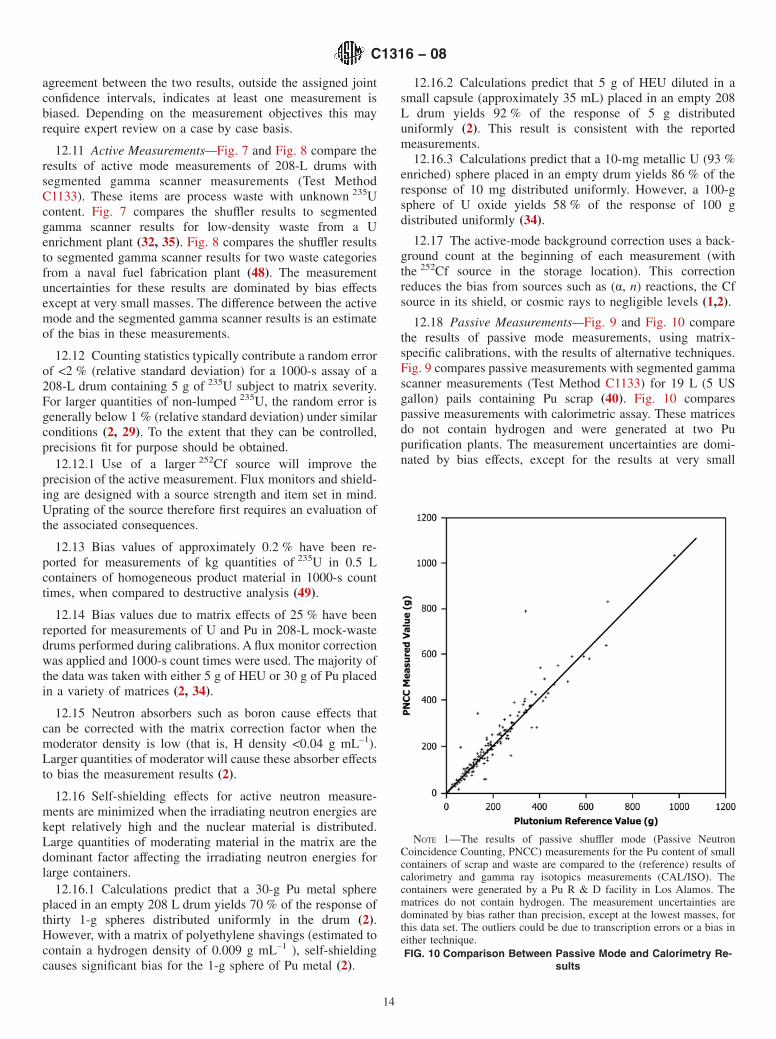
12.18 Passive Measurements—Fig. 9 and Fig. 10 comparethe results of passive mode measurements, using matrix-specific calibrations, with the results of alternative techniques.Fig. 9 compares passive measurements with segmented gammascanner measurements (Test Method C1133) for 19 L (5 USgallon) pails containing Pu scrap (40). Fig. 10 comparespassive measurements with calorimetric assay. These matricesdo not contain hydrogen and were generated at two Pupurification plants. The measurement uncertainties are domi-nated by bias effects, except for the results at very small
NOTE 1—The results of passive shuffler mode (Passive NeutronCoincidence Counting, PNCC) measurements for the Pu content of smallcontainers of scrap and waste are compared to the (reference) results ofcalorimetry and gamma ray isotopics measurements (CAL/ISO). Thecontainers were generated by a Pu R & D facility in Los Alamos. Thematrices do not contain hydrogen. The measurement uncertainties aredominated by bias rather than precision, except at the lowest masses, forthis data set. The outliers could be due to transcription errors or a bias ineither technique.FIG. 10 Comparison Between Passive Mode and Calorimetry Re-
sults
C1316 − 08
14

masses. The differences between the two techniques are anestimate of the bias in these measurements.
12.19 Counting statistics contribute a random error of lessthan 1 % for a 1000-s count of an item containing more than 1g 240Pueff of PuO2 (39). The precision is better for assays oflarger quantities of Pu.
12.20 Bias values of 2 % have been reported for measure-ments on small containers (1-L metal cans) of homogeneous Pumaterial, when compared to destructive analysis (39). The Pumasses ranged from 75 to 874 g; the counting times were 1000s; and no matrix correction was applied.
12.21 Bias values of 10 % have been reported for measure-ments of the Pu content in 208-L waste drums, performedduring calibration. A flux monitor correction was applied and1000-s count times were used. Most of the data is from 30 g ofPu placed in a variety of matrices (2, 34).
12.22 The bias due to cosmic-ray background can be on theorder of 0.02-g 240Pueff for large dense items at sea level andcan double at an elevation of 2000 m (4). Corrections can bemade if necessary (45). Cosmic ray induced rates depend onthe mass and atomic number of the matrix materials, Pb havinga far higher specific production rate than most other commonmatrix materials such as combustibles and steel (19).
12.23 The coincidence requirement corrects the passivemeasurement for the presence of (α, n) neutrons. Whenmultiplication is present, a bias can result. The bias effects dueto neutron multiplication increase with Pu mass and areaffected by variations in the distribution of the Pu and thepresence of moderating and (α, n) materials.
12.23.1 Waste measurements of matrices with uniformlydistributed special nuclear material in 208-L drums exhibitnegligible multiplication.
12.23.2 A multiplication effect of 9 % on the neutroncoincidence rate has been reported for 10 g of 240 Pueff presentin Pu oxide (39, 40). The effect will decrease if the Pu is dilutedby a matrix.
12.24 Neutron absorbers have negligible effects on theaccuracy of passive coincidence measurements of unmoderatedsamples.
12.25 Self-shielding effects do not exist for passive neutronmeasurements.
13. Keywords
13.1 active neutron measurements; californium;californium-252; NDA; neutron coincidence counting; PAN;passive neutron measurements; plutonium; scrap measure-ments; shuffler; uranium; waste measurements
REFERENCES
(1) Rinard, P. M., “Shuffler Instruments for the Nondestructive Assay ofFissile Materials,” Los Alamos report LA-12105, May 1991.
(2) Rinard, P. M., Adams, E. L., Menlove, H. O., and Sprinkle, J. K., Jr.,“Nondestructive Assays of 55-gallon Drums Containing Uranium andTransuranic Waste Using Passive/Active Shufflers,” Los Alamosreport LA-12446-MS, 1992.
(3) C. Eid and P. Bernard, Eds., “Non-Destructive Assay of RadioactiveWaste,” Proceedings of the Topical Meeting at Cadarache, France,EUR-12830, November 1989.
(4) D. Reilly, N. Ensslin, H. Smith, Jr., and S. Kreiner, Eds., “PANDA—Passive Nondestructive Assay of Nuclear Materials,” LA-UR-90-732,NUREG/CR-5550, March 1991.
(5) Roberts, R., Meyer, R., Hafstad, L. and Wang, P., “The DelayedNeutron Emission Which Accompanies Fission of Uranium andThorium”, Physics Review, 55, 664, 1939.
(6) Cavallari, F., Terrani, M. and Terrani, S., “The Analysis of FissileNuclide Mixtures by Delayed Neutron Emission”, Nuclear Instru-ments and Methods 79 ( 1970) p. 69–76.
(7) Chard, P. M. J. and Croft S., “A database of 240Pueffective and 235Uef-
fective coefficients for various fertile and fissile isotopes”, 19th AnnualESARDA Symposium, Montpellier, France, May, 1997. ESARDA 28EUR 17665 EN(1997) p. 389–396.
(8) Long, S. M., Hsue, F., Hoth, C., Fernandez, R., Bjork, C. andSprinkle, J., “Design and Fabrication of 55-Gallon Drum ShufflerStandards”, 35th INMM, Naples, Florida, July 17-20, 1994, p.470–473.
(9) Werner, C.J., “Simulation of Delayed Neutrons Using MCNP”,Progress in Nuclear Energy, Vol. 41, No. 1–4, p. 385–389, 2002.
(10) Mount, M. E., O’Connell, W. J., Cochran, C. W. and Rinard, P. M.,“Calibration Tools for Measurement of Highly Enriched Uranium inOxide and Mixed Uranium-Plutonium Oxide with a Passive-ActiveNeutron Drum Shuffler”, INMM, 44th Annual Meeting, Phoenix,AZ, July 13–17 2003.
(11) Rinard, P. M., “Calculating Accurate Shuffler Count Rates withApplications”, 42nd INMM, 15–19 July 2001, Indian Wells,California, USA. CD-ROM, 2001.
(12) Menlove, H. O. and Eccleston, G. W., “High-Sensitivity Measure-ments for Low-Level TRU Wastes Using Advanced Passive NeutronTechniques”, presented at the TRU Waste CharacterizationConference, Pocatello, Idaho, August, 1992.
(13) Rinard, P. M., Kroncke, K. E., Schneider, C. M., Biddle, R. S.,Sadowski, E. T. and Studly, R. V., “A Shuffler for Uranium Billets”,32nd INMM, New Orleans, July 28–31, 1991, p. 449–454.
(14) Rinard, P. M., Sadowski, E. T. and Armstrong, F. G., “Billet ShufflerCalibration Data and Interpolation Schemes”, Los Alamos reportLA-12351-MS.
(15) Chard, P. M. J. and Croft, S., “Self-shielding factors for theCf-shuffler neutron interrogation technique”, 17th Annual ESARDASymposium, Aachen, Germany, May, 1995. ESARDA 27 EUR16290 EN(1995) p. 557–562.
(16) Chard, P. M. J., Bourva, L. C-A. and Croft, S., “A Review of SelfShielding Effects in Active Neutron Interrogation”, 23rd AnnualESARDA Symposium, Bruges, Belgium, May, 2001. EUR 19944EN (2001) p. 540–551. ISBN 92-894-1818–4.
(17) Packer, T. W., Swinhoe, M. T. and Syme, D. B., “Non-DestructiveAssay of the Fissile Content of Radioactive Waste Using a Califor-nium Shuffler”, 11th ESARDA Symposium, Luxembourg, May/June1989, p. 509–514.
(18) Crane, T. W., “Detectability Limits and Precision for Shufflers”, LosAlamos reports LA-10158-MS, August 1984.
(19) Croft, S. and Bourva, L. C-A., “The Specific Total and CoincidenceCosmic Ray Induced Neutron Production Rates in Materials”,Nuclear Instruments and Methods in Physics Research A505 (2003)p. 536–539.
(20) Croft, S., Alvarez, E., Curtis, D., McElroy, R. D., Wilkins, C. G.,Wormald, M. R. and Young, B., “The Estimation of the Minimum
C1316 − 08
15

Detectable Activity from Measured Passive Coincidence CounterData”, Proceedings of 46th Annual Meeting of the INMM, July10-14 2005, Phoenix, Arizona, USA. Paper 344. CD-ROM, 2005.
(21) McClelland, P. and Croft, S., “Commissioning results for NDA20: ACalifornium Shuffler Based Passive/Active Neutron Instrument forMeasuring Fissile Material in 200 litre LLW Drums at Dounreay”,22nd Annual European Safeguards Research and DevelopmentAssociation meeting on “Strengthening of Safeguards: Integratingand New and the Old”, Dresden, Germany, 9–11 May 2000, EUR19587 EN 464–471.
(22) Chard, P. M. J., McClelland, P. D. and Croft, S., “Optimisation of thePerformance of a Low Level Waste Passive/Active Neutron Interro-gation System”, Proceedings of the 43rd Annual Meeting of theInstitute of Nuclear Materials Management, Orlando, Florida, June23-27 2002 . CD-ROM, 2002 Documation, LLC. Session A:Wednesday Afternoon 26th June. Material Control & Accountancy–Combined Measurement Methods. Paper #320.
(23) Menlove, H.O. and Crane, T. W., “A 252Cf Based NondestructiveAssay System for Fissile Material”, Nuclear Instruments and Meth-ods 152 ( 1978) p. 549–557.
(24) MacMurdo, K. W. and Bowman, W. W., “Assay of Fissile Materialsby a Cyclic Method of Neutron Activation and Delayed-NeutronCounting”, Nuclear Instruments and Methods 141 ( 1977) p.299–306.
(25) Chard, P. M. J., Cooper, T. J., Croft, S., Lambert, K. P., Syme, D. B.and Wilkins, C. G., “Design philosophy for the new Harwell α,ß/γILW facility and associated NDA instrumentation with regard tocriticality safety”, Proc. of the 16th annual meeting of Institute ofNuclear Materials Management Japan Chapter, December 7-8 1995,Gakushi Kaikan 3–28, Kanda-Nikshiki-machi, Chiyoda-ku, Tokyo.
(26) Chard, P. M. J., Croft, S., Wilkins, C. G. and Preston, G. S., “AnExpert System for the Harwell ILW waste assay facility”, Proceed-ings of the 7th International Conference on Radioactive WasteManagement and Environmental Remediation, Nagoya, Japan,26–30 September 1999, ICEM ’99 CD ROM ISBN 0-7918-1966-3,Session 32, Paper 1.
(27) Argyle, J. P., Chard, P. M. J., Croft, S., Wilins, C. G. and Whyke, D.,“Measurement of the uranium content of intermediate level wastefrom the Sellafield DryPac plant by active neutron interrogation”,Proceedings WM’01 – WM Symposia Inc, Waste ManagementConference, Tucson, Arizona, 25 February-1 March 2001, CD-ROM, 2001 LaserOption Inc, Session 55, Paper 5.
(28) Croft, S., Bourva, L. C-A., Wilkins, C. G., Chard, P. M. J., Fisher, J.C. and Whyke, D., “The Calibration of the Sellafield DryPac PlantCf Shuffler”, Proceedings of the 43rd Annual Meeting of the Instituteof Nuclear Materials Management, Orlando, Florida, June 23-272002. CD-ROM, 2002 Documation, LLC. Session A: WednesdayMorning 26th June. Material Control & Accountancy –Calibrationand Measurement Control. Paper #30.
(29) Sprinkle, J. K., Jr., Menlove, H. O., Ensslin, N. and Crane, T. W.,“Measurements of Uranium Waste Using a Californium Shuffler”,Proceedings of the Topical Meeting at Cadarache, France, C. Eid andP. Bernard, Eds., EUR-12890, November, 1989, p. 202.
(30) Chard, P. M. J. and Croft S., “Review of source tailoring techniquesfor active neutron assay of uranium waste in safeguards”, 21stAnnual ESARDA Symposium, Seville, Spain, May, 1999. ESARDA29 EUR 18963 EN(1999) p. 407–410.
(31) Hurd, J. R., Hsue, F., Rinard, P. M. and Wachter, J. R., “Installationof Passive-Active Shufflers at Los Alamos Plant Environments”,35th INMM, Naples, Florida, July 17–20, 1995, p.438–443.
(32) Gross, J. C. and Wines, K. M., “Calibration Techniques and Resultsfor the Portsmouth Cf Shuffler”, presented at the XXXIV AnnualMeeting of the Institute of Nuclear Materials Management,Scottsdale, Arizona, July 1993, p 924–929.
(33) Croft, S., Philips, S. and Venkataraman, R., “Calibrating Passive
Neutron Multiplicity and Waste Counters Using Calibrated 252CfSources: Estimating aPu-Values Without Pu”, Proceedings of 46thAnnual Meeting of the INMM, July 10-14 2005, Phoenix, Arizona,USA. Paper 335. CD-ROM, 2005.
(34) Rinard, P. M., Coop, K. L., Nicholas, N. J. and Menlove, H. O.,“Comparison of Shuffler and Differential Die-Away-Technique In-struments for the Assay of Fissile Materials in 55-Gallon WasteDrums”, Los Alamos document LA-UR-93-2649, Journal ofNuclear Materials Management, Vol XXII, No. IV, 1994, p. 28–38.
(35) Wines, K. M. and Gross, J. C., “Comparison of Results from the CfShuffler and Segmented Gamma Scanner NDA Techniques”, pre-sented at the XXXV Annual Meeting of the Institute of NuclearMaterials Management, Naples, Florida, July 1994, p. 877 –881.
(36) Menlove, H. O., “Accurate Plutonium Waste Measurements Usingthe 252Cf Add-a-Source Technique for Matrix Corrections”, pre-sented at the XXXIII Annual Meeting of the Institute of NuclearMaterials Management, Orlando, Florida, July 1992.
(37) Stewart, J. E., Ferran, R. R., Menlove, H. O., Horley, E. C., Baca, J.,France, S. W. and Wachter, J. R., “A Versatile Passive/ActiveNeutron Coincidence Counter for In-Plant Measurements of Pluto-nium and Uranium”, presented at the 13th ESARDA Symposium,Avignon, France, May, 1991.
(38) Pickrell, M. M. and Rinard, P. M., “Matrix and Position Correctionof Shuffler Assays by Application of the Alternating ConditionalExpectation Algorithm to Shuffler Data”, presented at the XXXIIIAnnual Meeting of the Institute of Nuclear Materials Management,Orlando, Florida, July 1992.
(39) Sprinkle, J. K., Jr., Bosler, G. E., Hsue, S.-T., Kellogg, M. P., Miller,M. C., Simmonds, S. M. and Smith, H. A., “Nondestructive Assay ofPlutonium-Bearing Scrap and Waste”, Los Alamos document LA-UR-89-2373 presented at the ANS meeting, San Francisco, Novem-ber 1989.
(40) Baker, L., MacMurdo, K., Miller, M. C. and Bosler, G. E., “RecentExperiences of Scrap and Waste Assay Using Neutron CoincidenceCounting of Materials from F B-line at the Savannah River Site”,presented at the XXXI Meeting of the Institute of Nuclear MaterialsManagement, Los Angeles, CA, July 1990.
(41) Krick, M. S. and Harker, W. C., “NCC User’s Manual,” Los Alamosreport, to be published.
(42) Menlove, H. O., Abedin-Zadeh, R. and Zhu, R., “The Analyses ofNeutron Coincidence Data to Verify Both Spontaneous-Fission andFissionable Isotopes”, Los Alamos report LA-11639-MS, August1989.
(43) “European Interlaboratory Test Measurements on Alpha-Contaminated Waste”, R. Dierckx, Ed., Commission of the EuropeanCommunities report EUR-12609-EN, 1990.
(44) Hsue, S.-T., Campbell, K. and Barlich, G., “Measurement ControlProgram for New Special Recovery”, Los Alamos report LA-10974-MS, April 1987 .
(45) Miller, D. W., and Menlove, H. O., “Cosmic-Ray-Veto DetectorSystem”, Los Alamos report LA-12469-MS, December 1992.
(46) Menlove, H. O., Foster, L. A. and Baca, J., “NBC Operation ManualIncluding the Multi-Position Add-a-Source Function”, Los Alamosreport LA-12737-M, March 1994.
(47) Binney, S. E. and Scherpelz, R. I., “A Review of the Delayed FissionNeutron Technique”, Nuclear Instruments and Methods 154 ( 1978)p. 413–431.
(48) Strittmatter, R. B., Crane, T., Ensslin, N., Marks, T., Sprinkle, J. K.,Jr. and Tape, J. W., “Evaluation of Nondestructive Assay Measure-ments at the Nuclear Fuel Services Fuel Fabrication Plant”, LosAlamos report Q-1-82-424-7, April 1982.
(49) “Safeguards and Security Progress Report”, Los Alamos reportsLA-10787-PR (Jan.–Dec. 1985) and LA-11120-PR (Jan.–Dec.1986).
C1316 − 08
16

ASTM International takes no position respecting the validity of any patent rights asserted in connection with any item mentionedin this standard. Users of this standard are expressly advised that determination of the validity of any such patent rights, and the riskof infringement of such rights, are entirely their own responsibility.
This standard is subject to revision at any time by the responsible technical committee and must be reviewed every five years andif not revised, either reapproved or withdrawn. Your comments are invited either for revision of this standard or for additional standardsand should be addressed to ASTM International Headquarters. Your comments will receive careful consideration at a meeting of theresponsible technical committee, which you may attend. If you feel that your comments have not received a fair hearing you shouldmake your views known to the ASTM Committee on Standards, at the address shown below.
This standard is copyrighted by ASTM International, 100 Barr Harbor Drive, PO Box C700, West Conshohocken, PA 19428-2959,United States. Individual reprints (single or multiple copies) of this standard may be obtained by contacting ASTM at the aboveaddress or at 610-832-9585 (phone), 610-832-9555 (fax), or [email protected] (e-mail); or through the ASTM website(www.astm.org). Permission rights to photocopy the standard may also be secured from the Copyright Clearance Center, 222Rosewood Drive, Danvers, MA 01923, Tel: (978) 646-2600; http://www.copyright.com/
C1316 − 08
17


![Calibration of Nondestructive Assay Instruments: An ... · and are given in [5]without further justification. A model that is linear in the predictor is assumed. If explorato-ry analysis](https://img.pdfslide.net/doc/110x75/5e737a2306700c0d96353759/calibration-of-nondestructive-assay-instruments-an-and-are-given-in-5without.jpg)