Embed Size (px)
Citation preview
Standardization of the Repair Procedure
for the A380-800 HTP External Rib Flanges
Claudia [email protected]
Instituto Superior Tecnico, Lisboa, Portugal
January 2014
Abstract
As a worldwide leader on commercial aircraft production, Airbus is constantly searching for themost efficient and sound methods of response to the transportation services industry. The currentstudy, in particular, focuses on the pursue for fast and reliable solution for material damages repairon a specific group of ribs used in the Horizontal Tail Plane (HTP) box of the Airbus aircraft modelA380, namely ribs 10 to 25. There are a total of 388 rib flanges, globally sharing their main structuralfunction and some geometric characteristics. The damages these rib regions present happen mostof all on the HTP assembly line, in Getafe. Each time there is a defect or damage on a rib flangewith no possible rework other than to trim the flange, it is necessary to manufacture an additionalangle (or to use an exactly equal one) and to perform the correspondent validation complying allthe requirements demanded by the airworthiness principles and regulations. This process takes aconsiderable amount of lead-time. With this in mind, this study intends to present a repair solutionthrough a minimum set of standard flanges fit to properly repair and restore the maximum number ofrib flanges. This will not only simplify and diminish these types of damage repair engineering workloadto future incidents but also decrease the repair process lead-time, working towards the damage han-dling methods optimization, and helping on the increase of the annual delivery rate of the A380 aircraft.
Keywords: Airbus, A380, HTP, Torsion box rib, Standardization procedure, Damage repair.
1. Introduction
The main goal of this study is to standardize the re-pair procedure for a specific group of ribs used in theHorizontal Tail Plane (HTP) box of the Airbus air-craft model A380, namely ribs 10 to 25. There area total of 388 flanges on these ribs, globally sharingtheir main structural function and some geomet-ric characteristics. The damages these rib regionspresent happen most of all on the HTP assemblyline, in Getafe.
Each time there is a defect or damage on a ribflange with no possible rework other than to trimthe flange, it is necessary to manufacture an addi-tional angle (or to use an exactly equal one) andto perform the correspondent validation complyingall the requirements demanded by the airworthi-ness principles and regulations. This process takesa considerable amount of lead-time mainly due tothe part manufacturing phase. The production siteis not on the same city as the assembly, and themanufacture process may cause disturbs on the gen-eral production rate. With this in mind, this studyintends to present a repair solution through a min-
imum set of standard flanges fit to properly repairand restore the maximum number of rib flanges.This will not only simplify and diminish these typesof damage repair engineering workload to future in-cidents but also decrease the repair process lead-time, working towards the damage handling meth-ods optimization, and helping on the annual deliv-ery rate of the A380 aircraft.
The project developed was part of an eightmonth internship program on the Airframe En-gineering department (ESTN1, currently workingwith the A380 wing ribs, horizontal stabilizer,vertical stabilizer, and rudder) at Airbus SAS inthe Getafe site (Madrid, Spain), resulting froman agreement between IST, Airbus SAS and FUE(Funcadion Universidad Empresa).
1.1. Airbus
Airbus SAS is an EADS (European Aeronautic De-fence and Space Company) currently with a 51%market share on commercial aircraft above 100 seatsmaintaining the company’s global leadership on thissector [1].
1
Particularly with the A380, the current annualdelivery rate of 25 aircraft is moving towards a rateof 30, based on improved production processes thatare now in place [2]. The company’s Global MarketForecast for 2013-2032 [3] predicts the continuinggrowth of the demand for Very Large Aircraft(VLA) and more efficient aircraft, estimating aneed for more than 1300 VLAs by the year of2032 [3]. As a measure of the production responsetime improvement process, the quick and effectiveanswer to manufacture deviations and/or defectson the assembly process requests careful analysisand constant updates through an aircraft modellifetime, the present study is part of this effort.
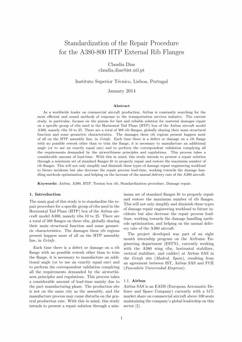
1.2. A380 AircraftThis subsonic very long-range commercial transportaircraft powered by four engines presents two full-length payload decks and a lower cargo deck (itsoverall dimensions are illustrated on Figure 1).
(http://www.a350xwbfirstflight.com/)
… / A380(aircraftfamilies/passengeraircraft/a380family/) / Dimensions & key data
DIMENSIONS & KEY DATA
Greener, cleaner, quieter and smarter – the A380 is a game changer in terms of aircraft performance, cost efficiency, comfort
and sustainable growth.
A380 SPECIFICATIONS
Key figures Go to details
(javascript:;)Metric Imperial
Range 15 700 km
Typical seating x
525 (3-class)
Wing span 79.75 m
Overall length 72.72 m
Height 24.09 m
Go to key figures
(javascript:;)Metric Imperial
Dimensions
Overall
length
72.72 m
Cabin
length
Main
deck
49.90 m
Upper
deck
44.93 m
Fuselage
width
7.14 m
Max cabin
width
Main
deck
6.54 m
Upper
deck
5.80 m
Wing span
(geometric)
79.75 m
Height 24.09 m
Track 14.34 m
Capacity
Pax Typical
seating
525 (3-class)
Max 853
Freight LD3
capacity
underfloor
38 LD3
Max
pallet
number
underfloor
13
Bulk hold
volume
14.3 m³
Total
volume
184 m³
(containers+bulk)
Performance
Range 15 700 km
Mmo M0.89
Max ramp
weight
562 tonnes
Max take-
off weight
560 tonnes
Max
landing
weight
386 tonnes
Max zero
fuel
weight
361 tonnes
Max fuel
capacity
320 000 litres
Engines
Figure 1: Basic A380 overall dimensions [4].
The A380 is 25% made of composite material [5]demonstrating the effort on optimizing its globalstructure. Another relevant characteristic on thisaircraft is the existence of fuel tanks not only onthe wings but also on the horizontal stabilizer, thelatest working as a trimmable fuel tank.
This aircraft is the largest commercial airplaneflying nowadays and when compared to its directcompetition (the 747-400 and 747-8) the A380 of-fers a greater overall range, lower runway requireddistances (both for take-off and landing), lower ap-proach speed, quieter cabin conditions, a much bet-ter environmental sustainability with a smaller rel-ative fuel burn per seat, and the lowest operatingcost per seat (on a 6000nm sector) [4].
Until December 2013, there was a total of 304A380 orders with 122 delivered and operationalaircraft [6], making this the leading VLA currentlyon the market.
1.3. Cost ConsiderationsThe standardized repair method application has adirect effect on the repair cost, but in this study it
is not feasible to quantitatively estimate this conse-quence. A qualitative review is now presented.
Regarding the engineering workload, the stan-dard solution proposed still requires a scrupulousrepair analysis, so a few hours may be saved but thegreatest improvement comes on the global produc-tion lead-time (the time elapsed between the repairrequest and its conclusion). Notice that currentlywhen the manufacture of a new flange is required,an original rib mold must be used for this partic-ular function, which means that production timemight be lost due to two main reasons: the delayof the manufacture process of an actual completerib, if there is no other mold momentarily available;and also otherwise needed autoclave space might bewasted given the dimension of the rib mold used tomanufacture one specific flange. The transporta-tion time save is obvious when a small yet adequatestock of standard parts are kept on the assemblysite at Getafe (as stated on the previous paragraph,these parts are generally manufactured in Illescas).
To sum up, although there are no actual mon-etary data, the relation between time and costis easily acknowledge, and the standardizationbenefits are quantitatively proven as intended.
1.4. From the HTP to the Rib’s Flange
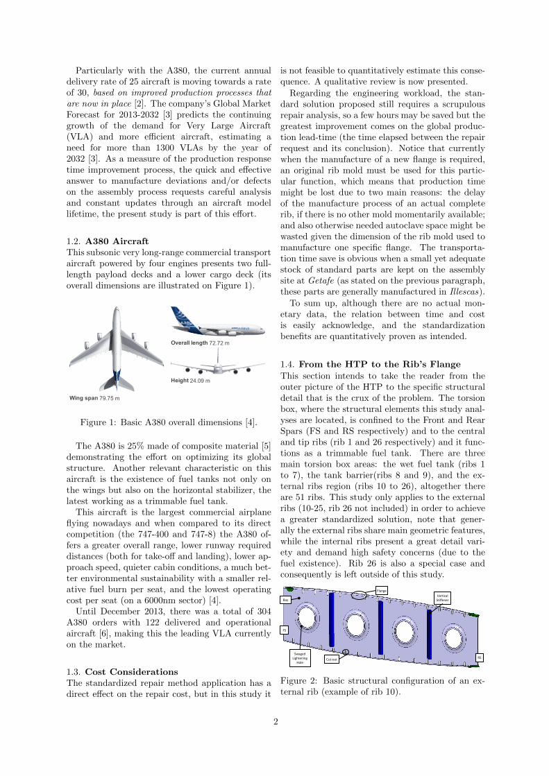
This section intends to take the reader from theouter picture of the HTP to the specific structuraldetail that is the crux of the problem. The torsionbox, where the structural elements this study anal-yses are located, is confined to the Front and RearSpars (FS and RS respectively) and to the centraland tip ribs (rib 1 and 26 respectively) and it func-tions as a trimmable fuel tank. There are threemain torsion box areas: the wet fuel tank (ribs 1to 7), the tank barrier(ribs 8 and 9), and the ex-ternal ribs region (ribs 10 to 26), altogether thereare 51 ribs. This study only applies to the externalribs (10-25, rib 26 not included) in order to achievea greater standardized solution, note that gener-ally the external ribs share main geometric features,while the internal ribs present a great detail vari-ety and demand high safety concerns (due to thefuel existence). Rib 26 is also a special case andconsequently is left outside of this study.
Bay Vertical Stiffener
Swaged Lightening
Hole Cut-out
Flange
RS
FS
Figure 2: Basic structural configuration of an ex-ternal rib (example of rib 10).
2
The general external rib model (exemplified atFigure 2) has a C-section profile and presents a di-vision in four distinctive bays by three vertical stiff-eners which are co-bonded on the outside of the rib’sprofile.
Stgr 1
Stgr 2
Original Fasteners
Figure 3: General example of external rib’s flangesattached to stringers.
The flange is the structural region that joints therib to the HTP skin, also crossing the stringer (orStgr), as Figures 2 and 3 show, the rib’s flangesare discontinued due to stringer cut-outs. Figure 3illustrates a general case of some flanges attachedto stringer and skin (one of the flanges is attachedby means of only one fastener due to being jointedto just one stringer).
Mainly the torsion box structural function isto provide torsional stiffness and support theHTP skin, and particularly the external ribs areexpected to support shear load (these are the loadsaccounted on document [7] and in this study)and consequently there are six main basic rib weblaminates with 100% of plies at ±45°.
1.5. Current Repair Method
This section exemplifies a general damaged flangessituation and its current repair procedure and con-sequent limitations (a real repair performed no theESTN1 department, [8]).
FS
Stgr 14
Stgr 13
Rib 11 LH
b)
View A 22mm
43mm
c)
Rib 11 LH a)
RS
FS
A
Figure 4: General damaged flange example (notethat it is the symetric side, the LH): a) flange loca-tion at rib 11 [9]; b) lower box drawing with flangelocation; c) flange region affected.
The example explored on this section is a damageon rib 11 from the Right Hand (RH) side, on theflange between stringers 13 and 14. Note that giventhe HTP general symmetry, Figure 4 illustrates the
correspondent damage location on the Left Hand(LH) side.
Currently the flange repair this study intendsto standardize is solved by trimming the damagedflange through the corner radius limit (red line, Fig-ure 5) cutting the edge corners with a proper radius(not necessarily the one depicted in Figure 5).
Figure 5: Rib trim for repair flange installation, rib11 from the HTP RH [8].
The flange is then replaced with an exactly equalpart (see Figure 6) from some unusable equivalentrib if available, or a new angular with the samegeometry and material characteristics is producedfrom the rib original mold.
Figure 6: Repair flange with the same geometry andmaterial as the original flange [8].
1.6. General Solution Approach
Knowing the general HTP and rib’s geometry andfunction, and the current repair procedure, themain standard solution guidelines may now be de-fined accounting some assumptions about the origi-nal flanges that should be verified at the end of thisstudy. These main assumptions and respective con-sequences are: small curvature level for the flanges’union to the HTP skin, which allows the definitionof an ideal surface plane for this flange surface; aper-ture angle close to 90° and consequently no regardto this aspect when performing the static strengthanalysis (this assumption is only accounted on therepair static strength analysis).
Since the main goal of this study is to standard-ize the flange repair procedure, we intend to obtaina reduced number of solution parts. Consequentlyit is not feasible to keep the original curved flangesurfaces along the project development. The firsttopic presented above is then a necessary approach.Both considerations will be verified along thisdocument.
3
2. Geometric StudyThis Chapter exposes the geometric standardiza-tion of the repair solution sought by this study.First of all the basic flange design parameters mustbe clarified and the relevant structural characteris-tics have to be methodically measured (due to spacelimitations, the measuring description/results areomitted on this Extended Abstract). Only then de-tailed analysis may be performed to evaluate the ge-ometric effects of a standard repair, define commoncharacteristics and verify the suitability of thesegeneralizations.
Formerly to the measurement step, it is requiredto determine a planar surface approach to each oneof the 388 rib flanges’ base. This was performedon CATIAr and it is a highly important projectphase, given the primal role these planes representon the search for geometrical patterns. Theplanes defined must properly portray the originalflanges base mainly accounting its aperture angle(explained next) and ensuring the fulfilment ofall requirements (also detailed on the followingSections). Each plane is defined by three pointslocated simultaneously on the stringer surfaceand on the lower surface of the flange’s base.Note that the following developments alreadyaccount with the existence of an ideal plane todefine a first solution approach for each flange base.
2.1. Standard Part Geometric Description
a)
b)
c)
𝒓
𝒉
𝜶
𝒕
𝒑 𝒍
𝒅
𝒘
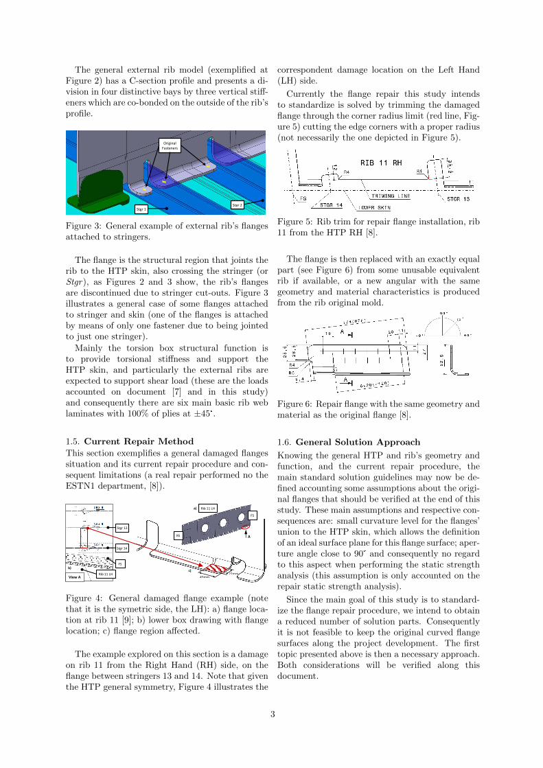
Figure 7: Global foot geometry from genericCATIAr model: a) lateral view; b) top view; c)isometric view.
The ribs follow the HTP aerodynamic profiles henceall flanges present some curvature level. Since thereproduction of all flanges curvature would not besuitable for the generalization principal that guidesthis study (as previously stated), it is assumed that
these curvatures are smooth enough to make pos-sible the repair of a lightly curved damaged footusing a repair flange with completely plane unionsurfaces, ultimately minimizing the number of re-quired standard solutions.
A generic basic repair part is then simply definedas an “L” structure (not necessarily with an aper-ture of 90°) as depicted in Figure 7, and its mostrelevant geometrical characteristics (also illustratedon this Figure) are:
� r - flange internal radius;
� t - laminate thickness;
� h - flange height;
� α - flange aperture angle;
� l - flange length;
� p - pitch between rivets;
� w - flange width (from the vertical laminatemid plane);
� d - fastening distance.
2.2. Geometric AnalysisThis Section intends to achieve the design stan-dardization for the repair solution combining thegeometry measurements standards and require-ments to be introduced next. At the end of thisanalysis the standard parts design should beglobally defined.
Aperture Angle and Maximum Gap Ad-missible Variations
In this study, given the manufacturing limita-tions discussed with the production team, the mostgeneric tolerances of ±0.5° will be regarded. Conse-quently the geometric analysis must be performedaccounting that the flange aperture angle α mayvary ±0.5° without causing severe consequences,and so a second important point is now considered:the effect of varying the aperture angle on the jointgap.
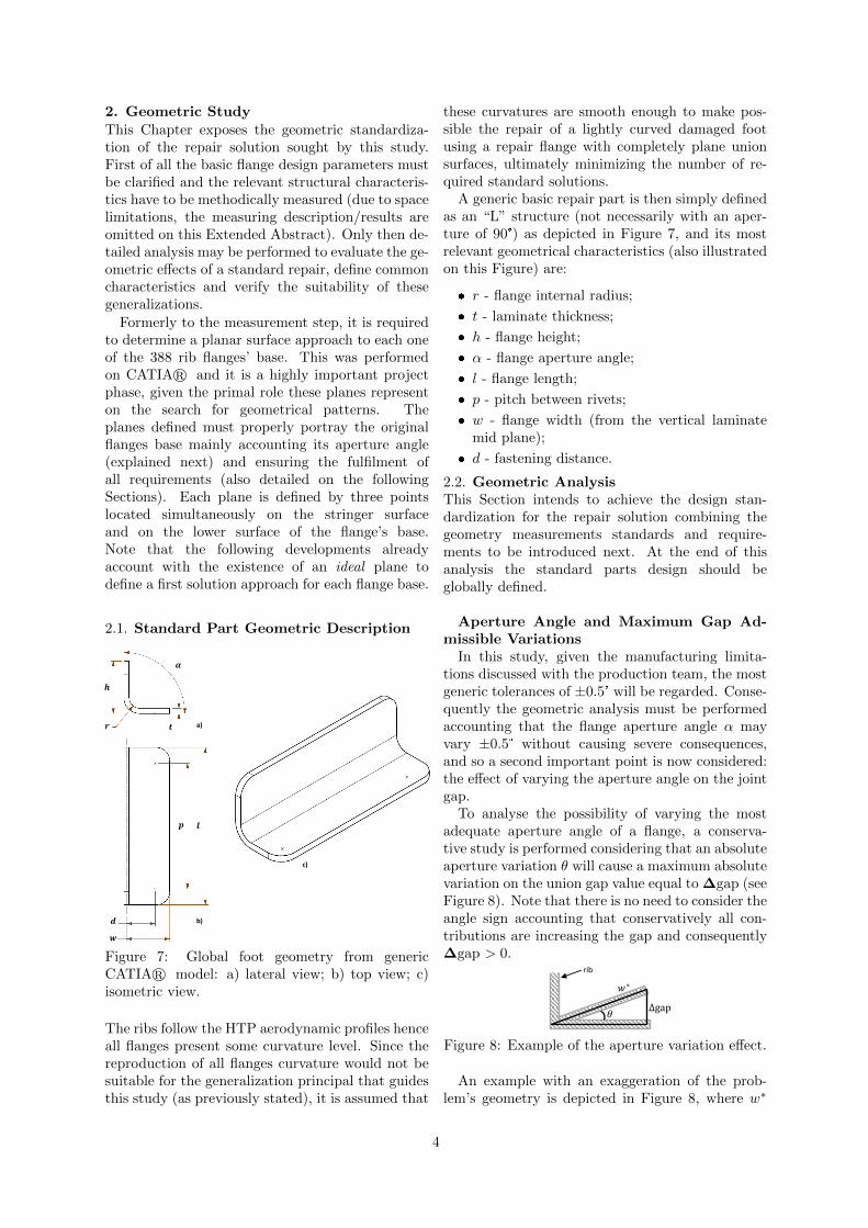
To analyse the possibility of varying the mostadequate aperture angle of a flange, a conserva-tive study is performed considering that an absoluteaperture variation θ will cause a maximum absolutevariation on the union gap value equal to ∆gap (seeFigure 8). Note that there is no need to consider theangle sign accounting that conservatively all con-tributions are increasing the gap and consequently∆gap > 0.
𝜃 ∆gap
𝑤∗
rib
Figure 8: Example of the aperture variation effect.
An example with an exaggeration of the prob-lem’s geometry is depicted in Figure 8, where w∗
4
is the width to account (in the worst scenario it isequal to w + t). From the ideal surface plane, theaperture angle measurements allow us to admit asmall angles approach and so (for angles in radi-ans) the gap variation is given by ∆gap ≈ w∗ × θ.
As stated previously, there are mandatory re-quirements when shimming parts in order to achievea proper and safe fitting. The maximum thicknessof the liquid shim is 0.5mm, but for mixed (liq-uid + solid) shims a total thickness of 1.2mm isacceptable. To find the aperture angle variationrestriction it is still necessary to discount from thisvalue two important parameters: the maximum gapthat would result from repairing the flange with theideal surface plane defined at the beginning of thegeometrical study, gapplane surf; the maximum gapthat could be caused in case of the maximum toler-ance variation happening (+0.5°), gapangle tol, thatdepends directly from the repair width. The re-sulting parameter is gapadmissible and leads us toobtain the allowable aperture angle variation fromθadmissible = gapadmissible/w
∗.
After defining the allowable aperture anglevariation, we have a range for every flange centredon the aperture angle measured from the ideal sur-face plane αmeasured and the estimated admissiblevariation: αmeasured ±θadmissible. When analysingthese results it is noticeable that there are a total ofeight inadequate situations (1 for the upper side, 7for the lower side) and other cases with an apertureangle admissibility too close to zero which is anundesirable situation. These cases may indicatethat the original plane was already unsuitableto use ion the repair or very sensitive regardingvariations. These results contribute as boundariesfor the creation of flange clusters through apertureangles.
Fastening Axis Inclination Tolerance
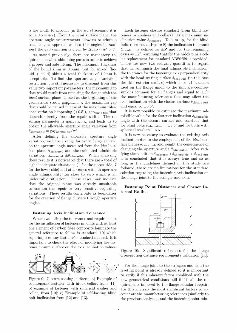
When evaluating the tolerances and requirementsfor the installation of fasteners in joints with at leastone element of carbon fibre composite laminate thegeneral reference to follow is standard [10] whichsuperimposes any fastener’s standard manual. It isimportant to check the effect of modifying the fas-tener closure surface on the axis inclination values.
c) b)
𝛿 𝛿
a)
Figure 9: Closure seating surfaces: a) Example ofcountersunk fastener with hi-lok collar, from [11];b) example of fastener with spherical washer andcollar, from [10]; c) Example of self-locking blindbolt inclination from [12] and [13].
Each fastener closure standard (from blind fas-teners to washers and collars) has a maximum in-clination value δstandard. To sum up, for the blindbolts (element c., Figure 9) the inclination toleranceδstandard is defined as ±5° and for the remainingcases as ±7°, assuming that for the hi-lok pins a col-lar replacement for standard ABS0259 is provided.There are now two relevant quantities to regardthat will diminish the final admissible inclination:the tolerance for the fastening axis perpendicularitywith the head seating surface δhead surf (in this casethe skin exterior surface) which since all fastenersused on the flange union to the skin are counter-sunk is common for all flanges and equal to ±1°;the manufacturing tolerances that may affect theaxis inclination with the closure surface δclosure surf
and equal to ±0.5°.It is now possible to estimate the maximum ad-
missible value for the fastener inclination δadmissible
angle with the closure surface and conclude thatfor blind bolts δadmissible = ±3.5° and for bolts withspherical washers ±5.5°.
It is now necessary to evaluate the existing axisinclination due to the employment of the ideal sur-face planes δmeasured, and weight the consequence ofchanging the aperture angle θadmissible. After veri-fying the condition δmeasured +θadmissible < δhead surf
it is concluded that it is always true and so aslong as the guidelines defined in this study arefollowed, there are no limitations for the standardsolution regarding the fastening axis inclination onthe flange joint to the stringer and skin.
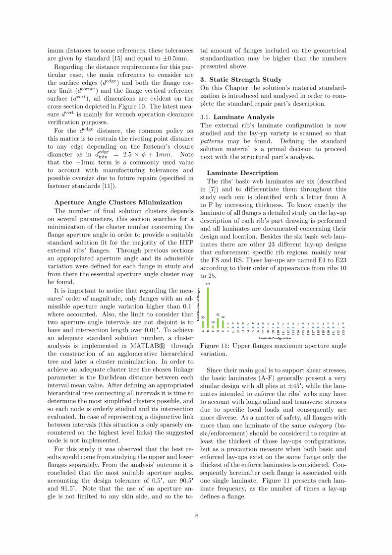
Fastening Point Distances and Corner In-ternal Radius
𝑑rivet
𝑑corner ≈ 2𝜙
𝑑vert
𝑑edge
Figure 10: Significant references for the flangecross-section distance requirements validation [14].
For the flange joint to the stringers and skin theriveting point is already defined so it is importantto verify if this inherent factor combined with thenew geometrical conditions still fulfils all the re-quirements imposed to the flange standard repair.For this analysis the most significant factors to ac-count are the manufacturing tolerances (similarly tothe previous analysis), and the fastening point min-
5
imum distances to some references, these tolerancesare given by standard [15] and equal to ±0.5mm.
Regarding the distance requirements for this par-ticular case, the main references to consider arethe surface edges (dedge) and both the flange cor-ner limit (dcorner) and the flange vertical referencesurface (dvert), all dimensions are evident on thecross-section depicted in Figure 10. The latest mea-sure dvert is mainly for wrench operation clearanceverification purposes.
For the dedge distance, the common policy onthis matter is to restrain the riveting point distanceto any edge depending on the fastener’s closurediameter as in dedge
min = 2.5 × φ + 1mm. Notethat the +1mm term is a commonly used valueto account with manufacturing tolerances andpossible oversize due to future repairs (specified infastener standards [11]).
Aperture Angle Clusters Minimization
The number of final solution clusters dependson several parameters, this section searches for aminimization of the cluster number concerning theflange aperture angle in order to provide a suitablestandard solution fit for the majority of the HTPexternal ribs’ flanges. Through previous sectionsan appropriated aperture angle and its admissiblevariation were defined for each flange in study andfrom there the essential aperture angle cluster maybe found.
It is important to notice that regarding the mea-sures’ order of magnitude, only flanges with an ad-missible aperture angle variation higher than 0.1°where accounted. Also, the limit to consider thattwo aperture angle intervals are not disjoint is tohave and intersection length over 0.01°. To achievean adequate standard solution number, a clusteranalysis is implemented in MATLABr throughthe construction of an agglomerative hierarchicaltree and later a cluster minimization. In order toachieve an adequate cluster tree the chosen linkageparameter is the Euclidean distance between eachinterval mean value. After defining an appropriatedhierarchical tree connecting all intervals it is time todetermine the most simplified clusters possible, andso each node is orderly studied and its intersectionevaluated. In case of representing a disjunctive linkbetween intervals (this situation is only sparsely en-countered on the highest level links) the suggestednode is not implemented.
For this study it was observed that the best re-sults would come from studying the upper and lowerflanges separately. From the analysis’ outcome it isconcluded that the most suitable aperture angles,accounting the design tolerance of 0.5°, are 90.5°and 91.5°. Note that the use of an aperture an-gle is not limited to any skin side, and so the to-
tal amount of flanges included on the geometricalstandardization may be higher than the numberspresented above.
3. Static Strength Study
On this Chapter the solution’s material standard-ization is introduced and analysed in order to com-plete the standard repair part’s description.
3.1. Laminate Analysis
The external rib’s laminate configuration is nowstudied and the lay-yp variety is scanned so thatpatterns may be found. Defining the standardsolution material is a primal decision to proceednext with the structural part’s analysis.
Laminate Description
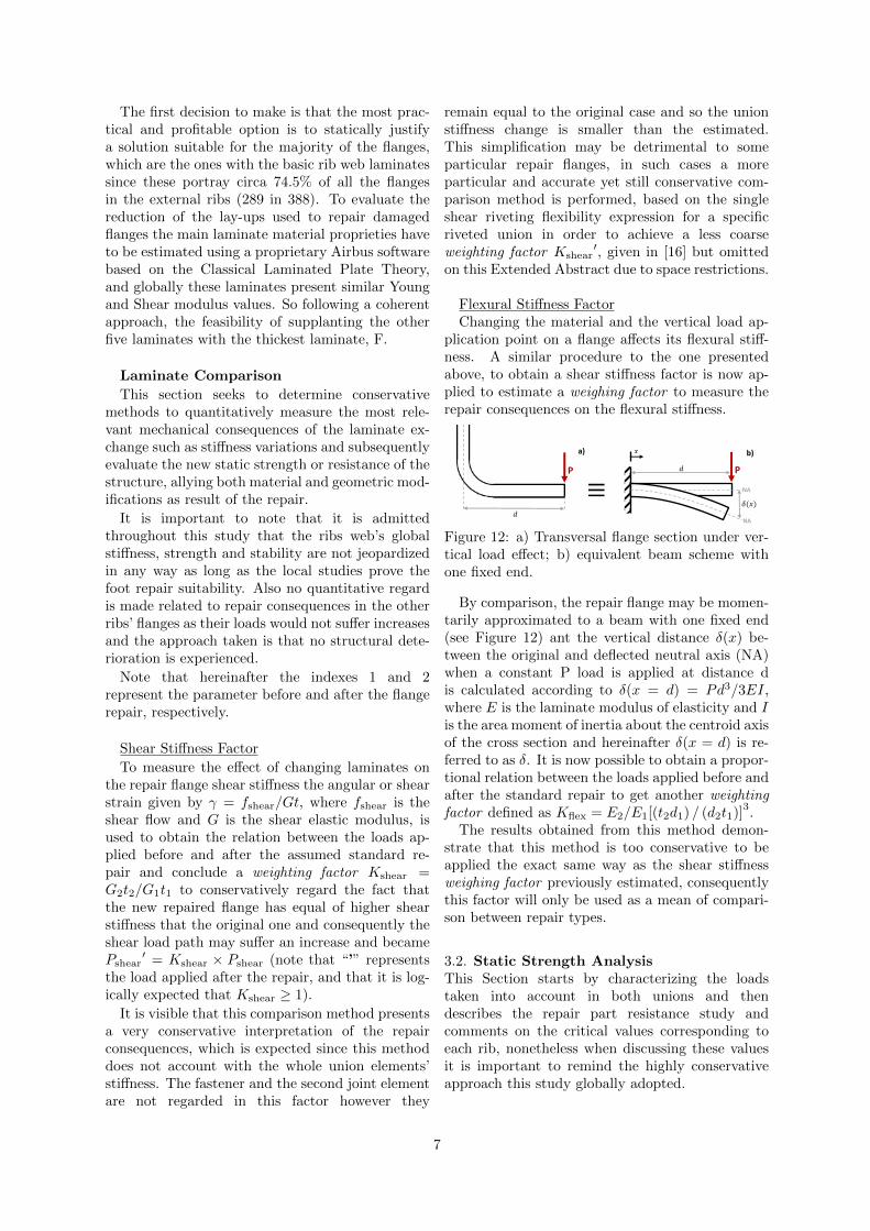
The ribs’ basic web laminates are six (describedin [7]) and to differentiate them throughout thisstudy each one is identified with a letter from Ato F by increasing thickness. To know exactly thelaminate of all flanges a detailed study on the lay-updescription of each rib’s part drawing is performedand all laminates are documented concerning theirdesign and location. Besides the six basic web lam-inates there are other 23 different lay-up designsthat enforcement specific rib regions, mainly nearthe FS and RS. These lay-ups are named E1 to E23according to their order of appearance from ribs 10to 25.
30
171
10
4232
4 6 6 6 2 6 3 6 2 3 5 2 4 4 1 6 2 6 6 3 6 6 2 6
A B C D E F
E1 E2 E3 E4 E5 E6 E7 E8 E9
E10
E11
E12
E13
E14
E15
E16
E17
E18
E19
E20
E21
E22
E23
Tota
l Nu
mb
er
of
Flan
ges
Laminate Configuration
Figure 11: Upper flanges maximum aperture anglevariation.
Since their main goal is to support shear stresses,the basic laminates (A-F) generally present a verysimilar design with all plies at ±45°, while the lam-inates intended to enforce the ribs’ webs may haveto account with longitudinal and transverse stressesdue to specific local loads and consequently aremore diverse. As a matter of safety, all flanges withmore than one laminate of the same category (ba-sic/enforcement) should be considered to require atleast the thickest of those lay-ups configurations,but as a precaution measure when both basic andenforced lay-ups exist on the same flange only thethickest of the enforce laminates is considered. Con-sequently hereinafter each flange is associated withone single laminate. Figure 11 presents each lam-inate frequency, as the number of times a lay-updefines a flange.
6
The first decision to make is that the most prac-tical and profitable option is to statically justifya solution suitable for the majority of the flanges,which are the ones with the basic rib web laminatessince these portray circa 74.5% of all the flangesin the external ribs (289 in 388). To evaluate thereduction of the lay-ups used to repair damagedflanges the main laminate material proprieties haveto be estimated using a proprietary Airbus softwarebased on the Classical Laminated Plate Theory,and globally these laminates present similar Youngand Shear modulus values. So following a coherentapproach, the feasibility of supplanting the otherfive laminates with the thickest laminate, F.
Laminate Comparison
This section seeks to determine conservativemethods to quantitatively measure the most rele-vant mechanical consequences of the laminate ex-change such as stiffness variations and subsequentlyevaluate the new static strength or resistance of thestructure, allying both material and geometric mod-ifications as result of the repair.
It is important to note that it is admittedthroughout this study that the ribs web’s globalstiffness, strength and stability are not jeopardizedin any way as long as the local studies prove thefoot repair suitability. Also no quantitative regardis made related to repair consequences in the otherribs’ flanges as their loads would not suffer increasesand the approach taken is that no structural dete-rioration is experienced.
Note that hereinafter the indexes 1 and 2represent the parameter before and after the flangerepair, respectively.
Shear Stiffness Factor
To measure the effect of changing laminates onthe repair flange shear stiffness the angular or shearstrain given by γ = fshear/Gt, where fshear is theshear flow and G is the shear elastic modulus, isused to obtain the relation between the loads ap-plied before and after the assumed standard re-pair and conclude a weighting factor Kshear =G2t2/G1t1 to conservatively regard the fact thatthe new repaired flange has equal of higher shearstiffness that the original one and consequently theshear load path may suffer an increase and becamePshear
′ = Kshear × Pshear (note that “’” representsthe load applied after the repair, and that it is log-ically expected that Kshear ≥ 1).
It is visible that this comparison method presentsa very conservative interpretation of the repairconsequences, which is expected since this methoddoes not account with the whole union elements’stiffness. The fastener and the second joint elementare not regarded in this factor however they
remain equal to the original case and so the unionstiffness change is smaller than the estimated.This simplification may be detrimental to someparticular repair flanges, in such cases a moreparticular and accurate yet still conservative com-parison method is performed, based on the singleshear riveting flexibility expression for a specificriveted union in order to achieve a less coarseweighting factor Kshear
′, given in [16] but omittedon this Extended Abstract due to space restrictions.
Flexural Stiffness FactorChanging the material and the vertical load ap-
plication point on a flange affects its flexural stiff-ness. A similar procedure to the one presentedabove, to obtain a shear stiffness factor is now ap-plied to estimate a weighing factor to measure therepair consequences on the flexural stiffness.
P
𝑑
𝛿(𝑥)
P 𝑑
𝑥
≡
a) b)
NA
NA
Figure 12: a) Transversal flange section under ver-tical load effect; b) equivalent beam scheme withone fixed end.
By comparison, the repair flange may be momen-tarily approximated to a beam with one fixed end(see Figure 12) ant the vertical distance δ(x) be-tween the original and deflected neutral axis (NA)when a constant P load is applied at distance dis calculated according to δ(x = d) = Pd3/3EI,where E is the laminate modulus of elasticity and Iis the area moment of inertia about the centroid axisof the cross section and hereinafter δ(x = d) is re-ferred to as δ. It is now possible to obtain a propor-tional relation between the loads applied before andafter the standard repair to get another weightingfactor defined as Kflex = E2/E1[(t2d1) / (d2t1)]
3.
The results obtained from this method demon-strate that this method is too conservative to beapplied the exact same way as the shear stiffnessweighing factor previously estimated, consequentlythis factor will only be used as a mean of compari-son between repair types.
3.2. Static Strength AnalysisThis Section starts by characterizing the loadstaken into account in both unions and thendescribes the repair part resistance study andcomments on the critical values corresponding toeach rib, nonetheless when discussing these valuesit is important to remind the highly conservativeapproach this study globally adopted.
7
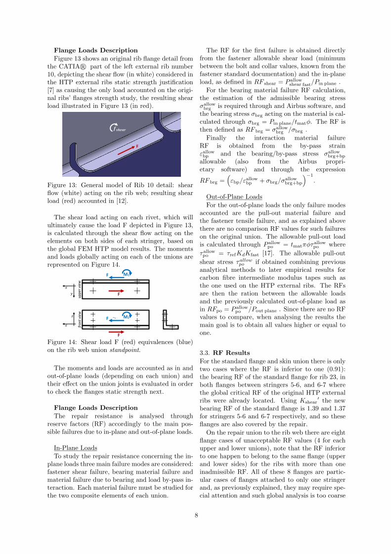
Flange Loads Description
Figure 13 shows an original rib flange detail fromthe CATIAr part of the left external rib number10, depicting the shear flow (in white) considered inthe HTP external ribs static strength justification[7] as causing the only load accounted on the origi-nal ribs’ flanges strength study, the resulting shearload illustrated in Figure 13 (in red).
𝒇𝒔𝒉𝒆𝒂𝒓
F
Figure 13: General model of Rib 10 detail: shearflow (white) acting on the rib web; resulting shearload (red) accounted in [12].
The shear load acting on each rivet, which willultimately cause the load F depicted in Figure 13,is calculated through the shear flow acting on theelements on both sides of each stringer, based onthe global FEM HTP model results. The momentsand loads globally acting on each of the unions arerepresented on Figure 14.
M2
…
F
F
M1 F
F
up
per
vie
w
fro
nt
view
𝑥
𝑦
𝑥
𝑧
Figure 14: Shear load F (red) equivalences (blue)on the rib web union standpoint.
The moments and loads are accounted as in andout-of-plane loads (depending on each union) andtheir effect on the union joints is evaluated in orderto check the flanges static strength next.
Flange Loads Description
The repair resistance is analysed throughreserve factors (RF) accordingly to the main pos-sible failures due to in-plane and out-of-plane loads.
In-Plane Loads
To study the repair resistance concerning the in-plane loads three main failure modes are considered:fastener shear failure, bearing material failure andmaterial failure due to bearing and load by-pass in-teraction. Each material failure must be studied forthe two composite elements of each union.
The RF for the first failure is obtained directlyfrom the fastener allowable shear load (minimumbetween the bolt and collar values, known from thefastener standard documentation) and the in-planeload, as defined in RF shear = P allow
shear fast/Pin plane .
For the bearing material failure RF calculation,the estimation of the admissible bearing stressσallow
brg is required through and Airbus software, andthe bearing stress σbrg acting on the material is cal-culated through σbrg = Pin plane/tmatφ. The RF isthen defined as RF brg = σallow
brg /σbrg .
Finally the interaction material failureRF is obtained from the by-pass strainεallow
bp and the bearing/by-pass stress σallowbrg+bp
allowable (also from the Airbus propri-etary software) and through the expression
RF brg =(εbp/ε
allowbp + σbrg/σ
allowbrg+bp
)−1
.
Out-of-Plane Loads
For the out-of-plane loads the only failure modesaccounted are the pull-out material failure andthe fastener tensile failure, and as explained abovethere are no comparison RF values for such failureson the original union. The allowable pull-out loadis calculated through P allow
po = tmatπφτallowpo where
τallowpo = τrefKdKfast [17]. The allowable pull-out
shear stress τallowpo if obtained combining previousanalytical methods to later empirical results forcarbon fibre intermediate modulus tapes such asthe one used on the HTP external ribs. The RFsare then the ration between the allowable loadsand the previously calculated out-of-plane load asin RFpo = P allow
po /Pout plane . Since there are no RFvalues to compare, when analysing the results themain goal is to obtain all values higher or equal toone.
3.3. RF Results
For the standard flange and skin union there is onlytwo cases where the RF is inferior to one (0.91):the bearing RF of the standard flange for rib 23, inboth flanges between stringers 5-6, and 6-7 wherethe global critical RF of the original HTP externalribs were already located. Using Kshear
′ the newbearing RF of the standard flange is 1.39 and 1.37for stringers 5-6 and 6-7 respectively, and so theseflanges are also covered by the repair.
On the repair union to the rib web there are eightflange cases of unacceptable RF values (4 for eachupper and lower unions), note that the RF inferiorto one happen to belong to the same flange (upperand lower sides) for the ribs with more than oneinadmissible RF. All of these 8 flanges are partic-ular cases of flanges attached to only one stringerand, as previously explained, they may require spe-cial attention and such global analysis is too coarse
8
to check this standardization suitability on theseflanges.
These eight flanges where excluded and theremaining 287 flanges representing circa 72% ofthe total flange number. In conclusion, the staticanalysis performed justifies the standard repairthrough laminate F for 72% of the A380 HTPexternal ribs flanges.
4. Standard SolutionFrom the geometric and static strength study’s con-clusions it is verified that the general solution ap-proaches are acceptable: the employment of planesurfaces for the repair part is appropriate to thisstudy’s purpose of maximizing the applicability ofthe standardization; and the final aperture anglesdefined for the part present values near the esti-mated 90° (more specifically +0.5° and +1.5°).
Combining the analysis conclusions and the mainmanufacturing concerns, the final standard solutionparts are finally determined.
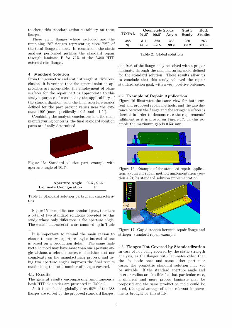
Figure 15: Standard solution part, example withaperture angle of 90.5°.
Aperture Angle 90.5°, 91.5°
Laminate Configuration F
Table 1: Standard solution parts main characteris-tics.
Figure 15 exemplifies one standard part, there area total of two standard solutions provided by thisstudy whose only difference is the aperture angle.These main characteristics are summed up in Table1.
It is important to remind the main reason tochoose to use two aperture angles instead of oneis based on a production detail. The same malemetallic mold may have more than one aperture an-gle without a relevant increase of neither cost norcomplexity on the manufacturing process, and us-ing two aperture angles improves the final resultsmaximizing the total number of flanges covered.
4.1. ResultsThe general results encompassing simultaneouslyboth HTP skin sides are presented in Table 2.
As it is concluded, globally circa 68% of the 388flanges are solved by the proposed standard flanges,
TOTALGeometric Study Static Both
91.5° 90.5° Any α Study Studies
388 311 320 363 280 263% 80.2 82.5 93.6 72.2 67.8
Table 2: Global solutions
and 94% of the flanges may be solved with a properlaminate, through the manufacturing mold definedfor the standard solution. These results allow usto conclude that this study achieved the repairstandardization goal, with a very positive outcome.
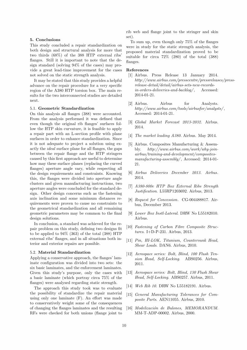
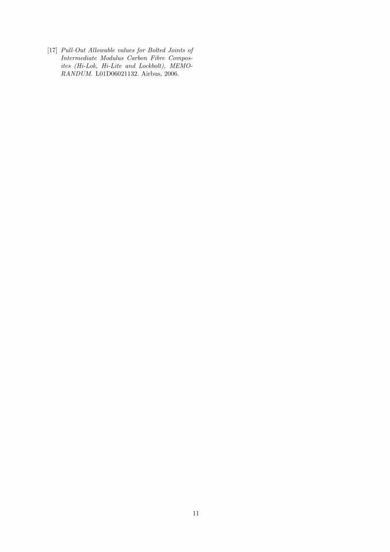
4.2. Example of Repair ApplicationFigure 16 illustrates the same view for both cur-rent and proposed repair methods, and the gap dis-tance between the flange and the stringer surfaces ischecked in order to demonstrate the requirements’fulfilment as it is proved on Figure 17. In this ex-ample the maximum gap is 0.531mm.
a)
b)
Figure 16: Example of the standard repair applica-tion; a) current repair method implementation (sec-tion 4.2); b) standard solution implementation.
Figure 17: Gap distances between repair flange andstringer, standard repair example.
4.3. Flanges Not Covered by StandardizationIn case of not being covered by the static strengthanalysis, as the flanges with laminates other thatthe six basic ones and some other particularcases, the geometric standard solution may yetbe suitable. If the standard aperture angle andinterior radius are feasible for that particular case,a different and more proper laminate may beproposed and the same production mold could beused, taking advantage of some relevant improve-ments brought by this study.
9
5. Conclusions
This study concluded a repair standardization onboth design and structural analysis for more thattwo thirds (68%) of the 388 HTP external ribs’flanges. Still it is important to note that the de-sign standard (solving 94% of the cases) may pro-vide a great lead-time improvement for the casesnot solved on the static strength analysis.
It may be stated that this study provides a helpfuladvance on the repair procedure for a very specificregion of the A380 HTP torsion box. The main re-sults for the two interconnected studies are detailednext.
5.1. Geometric Standardization
On this analysis all flanges (388) were accounted.From the analysis performed it was defined thateven though the original rib flanges’ surfaces fol-low the HTP skin curvature, it is feasible to applya repair part with an L-section profile with planesurfaces in order to enhance standardization. Sinceit is not adequate to project a solution using ex-actly the ideal surface plane for all flanges, the gapsbetween the repair flange and the HTP stringerscaused by this first approach are useful to determinehow may these surface planes (replacing the curvedflanges) aperture angle vary, while respecting allthe design requirements and constraints. Knowingthis, the flanges were divided into aperture angleclusters and given manufacturing instructions, twoaperture angles were concluded for the standard de-sign. Other design concerns such as the fasteningaxis inclination and some minimum distances re-quirements were proven to cause no constraints tothe geometrical standardization and all remaininggeometric parameters may be common to the finaldesign solutions.
In conclusion, a standard was achieved for the re-pair problem on this study, defining two designs fitto be applied to 94% (363) of the total (388) HTPexternal ribs’ flanges, and in all situations both in-terior and exterior repairs are possible.
5.2. Material Standardization
Applying a conservative approach, the flanges’ lam-inate configuration was divided into two sets: thesix basic laminates, and the enforcement laminates.Given this study’s purpose, only the cases witha basic laminate (which portray circa 75% of theflanges) were analysed regarding static strength.
The approach this study took was to evaluatethe possibility of standardize the repair materialusing only one laminate (F). An effort was madeto conservatively weight some of the consequencesof changing the flanges laminates and the resultingRFs were checked for both unions (flange joint to
rib web and flange joint to the stringer and skinset).
To sum up, even though only 75% of the flangeswere in study for the static strength analysis, theproposed material standardization proved to besuitable for circa 72% (280) of the total (388)flanges.
References[1] Airbus. Press Release 13 January 2014.
http://www.airbus.com/presscentre/pressreleases/press-release-detail/detail/airbus-sets-new-records-in-orders-deliveries-and-backlog/ , Accessed:2014-01-21.
[2] Airbus. Airbus for Analysts.http://www.airbus.com/tools/airbusfor/analysts/ ,Accessed: 2014-01-21.
[3] Global Market Forecast 2013-2032. Airbus.2014.
[4] The market leading A380. Airbus. May 2014.
[5] Airbus. Composites Manufacturing & Assem-bly. http://www.airbus.com/work/why-join-airbus/training-and-development/composites-manufacturing-assembly/ , Accessed: 2014-01-21.
[6] Airbus Deliveries December 2013. Airbus.2014.
[7] A380-800e HTP Box External Ribs StrengthJustification. L55RP1203692. Airbus, 2013.
[8] Request for Concession. CG-004488817. Air-bus, December 2013.
[9] Lower Box Instl-Lateral. DRW No L55182010.Airbus.
[10] Fastening of Carbon Fibre Composite Struc-tures. I+D-P-231. Airbus, 2013.
[11] Pin, HI-LOK, Titanium, Countersunk Head,Shear Loads. DAN6. Airbus, 2010.
[12] Aerospace series: Bolt, Blind, 100 Flush Ten-sion Head, Self-Locking. ABS0256. Airbus,2011.
[13] Aerospace series: Bolt, Blind, 130 Flush ShearHead, Self-Locking. ABS0257. Airbus, 2011.
[14] Web Rib 10. DRW No L55182191. Airbus.
[15] General Manufacturing Tolerances for Com-posite Parts. AEN11055. Airbus, 2010.
[16] Modelizacion de Bulones, MEMORANDUM.MM-T-ADP-00002. Airbus, 2000.
10
[17] Pull-Out Allowable values for Bolted Joints ofIntermediate Modulus Carbon Fibre Compos-ites (Hi-Lok, Hi-Lite and Lockbolt), MEMO-RANDUM. L01D06021132. Airbus, 2006.
11


![SinGAPORE AIRLInES A380* 456 ! A380] 333 A380 E 1531 …singapore airlines a380* 456 ! a380] 333 a380 e 1531 a330 [1-2-1 singapore airlines](https://img.pdfslide.net/doc/110x75/5f1f304da44bc1238e46c157/singapore-airlines-a380-456-a380-333-a380-e-1531-singapore-airlines-a380-456.jpg)