Embed Size (px)
Citation preview
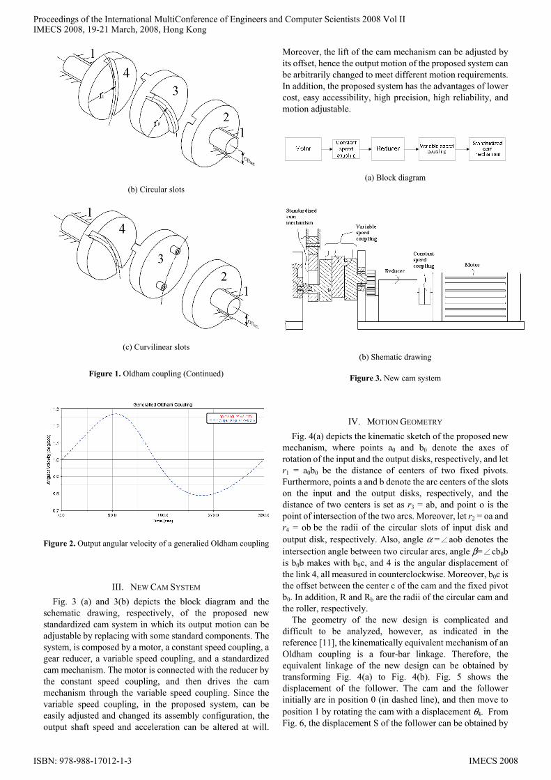
Abstract— The objective of this paper is to propose a novel
standardized cam system with motion adjustable. First, generalized Oldham couplings are described. Then, the proposed system is presented. It is composed by a motor, a constant speed coupling, a gear reducer, a variable speed coupling, and a standardized cam mechanism. Then, the feasibility is validated by kinematic simulation using ADAMS software. Finally, the prototype of proposed system is illustrated. The results show that the proposed system can produce required adjustable output motion. In addition, it has the advantage of lower cost, easy accessibility, and high precision.
Keywords: cam, Oldham coupling, kinematic simulation, ADAMS
I. INTRODUCTION A cam mechanism is composed by a cam, a follower, and
a frame. And the cam is used to transmit motion to the follower through a prescribed motion program by direct contact. Since cam mechanisms are compact and can produce complicated output in a simple way, they are extensively used in various kinds of machines and intruments. Typical examples of their applications include computer, internal combustion engine, printing presses, textile machines, and automatic machines, etc [1].
Once a cam mechanism has been designed and made, its output motion can not be altered. Whenever there is a design change, the cam has to be re-designed and re-manufactured. Moreover, since a cam mechanism needs precision machining, and is not a standard component, its building cost is higher than other mechanisms. Therefore, how to find an approach to solve these problems is an open topic to be investigated.
In 1991, Hsieh [2] firstly presented a novel approach to improve the state of the motion of the follower by varying the input speed using a servomotor. After that, Yan et al. [3-5] contributed to improve the output motion characteristics of a mechanism by a servomotor solution. Some researches [6-8] applied the method to a press. Although the method is effective, there are still some disadvantages exist due to the utilization of a servo motor, for instance, higher cost, a specially designed servomotor required, slow response, and limited output power. In 2007, Hsieh [9] investigated the feasibility of employing a cam-controlled planetary gear train to replace the servomotor.
Wen-Hsiang Hsieh is with Department of Automation Engineering,
National Formosa University, Yunlin 632, Taiwan, R.O.C. (tel: +886-5-6315368, fax: +886-6314486, e-mail: [email protected])
The objective of this work is to propose a novel standardized cam system with motion adjustable. Firstly, generalized Oldham couplings will be described, and their kinematic characteristics will be examined. Then, the proposed cam system will be presented in details. Finally, the feasibility will be verified by kinematic simulation using ADAMS software.
II. OLDHAM COUPLING An Oldham coupling has been used to transmit the motion
or the power between two parallel shafts. It can be classified, by the shape of its slots or ribs, as classical Oldham coupling (straight slot), generalized Oldham coupling with circular slots, and generalized Oldham coupling with curvilinear slots [10], as shown in Fig. 1(a)-(c), respectively. The generalized Oldham coupling consists of frame (link 1, not shown), input disk (link 2), floating disk (link 3), and output disk (link 4), as shown in Fig. 1(b). The radii, r1 and r2, of the centerline of the slots need not be equal, and the two centerlines are usually, but not necessary, designed to intersect at the axis of the floating disk. The classical Oldham coupling will transmit uniform motion between the input and output shafts. However, the generalized Oldham coupling with circular slots and curvilinear slots will transmit non-uniform motion, as shown in Fig. 2. The former is called constant speed coupling. The latter is called variable speed coupling in this work, and it leads to many potential applications to devices or machinery requiring non-uniform transmission.
(a) Classical
Figure 1. Oldham coupling
A Novel Standardized Cam Systems with Motion Adjustable
Wen-Hsiang Hsieh, Member, IAENG
Proceedings of the International MultiConference of Engineers and Computer Scientists 2008 Vol IIIMECS 2008, 19-21 March, 2008, Hong Kong
ISBN: 978-988-17012-1-3 IMECS 2008
(b) Circular slots
(c) Curvilinear slots
Figure 1. Oldham coupling (Continued)
Figure 2. Output angular velocity of a generalied Oldham coupling
III. NEW CAM SYSTEM Fig. 3 (a) and 3(b) depicts the block diagram and the
schematic drawing, respectively, of the proposed new standardized cam system in which its output motion can be adjustable by replacing with some standard components. The system, is composed by a motor, a constant speed coupling, a gear reducer, a variable speed coupling, and a standardized cam mechanism. The motor is connected with the reducer by the constant speed coupling, and then drives the cam mechanism through the variable speed coupling. Since the variable speed coupling, in the proposed system, can be easily adjusted and changed its assembly configuration, the output shaft speed and acceleration can be altered at will.
Moreover, the lift of the cam mechanism can be adjusted by its offset, hence the output motion of the proposed system can be arbitrarily changed to meet different motion requirements. In addition, the proposed system has the advantages of lower cost, easy accessibility, high precision, high reliability, and motion adjustable.
(a) Block diagram
(b) Shematic drawing
Figure 3. New cam system
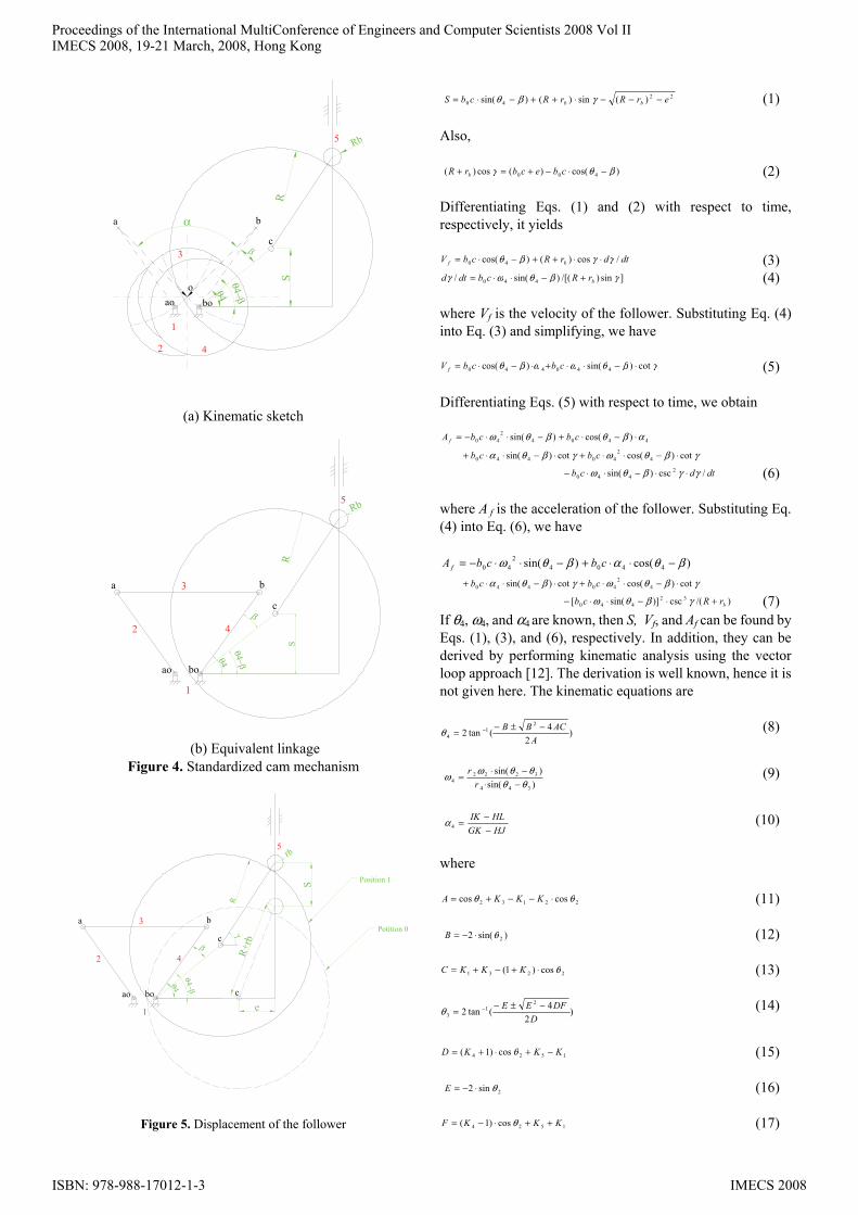
IV. MOTION GEOMETRY Fig. 4(a) depicts the kinematic sketch of the proposed new
mechanism, where points a0 and b0 denote the axes of rotation of the input and the output disks, respectively, and let r1 = a0b0 be the distance of centers of two fixed pivots. Furthermore, points a and b denote the arc centers of the slots on the input and the output disks, respectively, and the distance of two centers is set as r3 = ab, and point o is the point of intersection of the two arcs. Moreover, let r2 = oa and r4 = ob be the radii of the circular slots of input disk and output disk, respectively. Also, angle α = aob denotes the ∠
intersection angle between two circular arcs, angle β= cb∠ 0b is b0b makes with b0c, and 4 is the angular displacement of the link 4, all measured in counterclockwise. Moreover, b0c is the offset between the center c of the cam and the fixed pivot b0. In addition, R and Rb are the radii of the circular cam and the roller, respectively.
The geometry of the new design is complicated and difficult to be analyzed, however, as indicated in the reference [11], the kinematically equivalent mechanism of an Oldham coupling is a four-bar linkage. Therefore, the equivalent linkage of the new design can be obtained by transforming Fig. 4(a) to Fig. 4(b). Fig. 5 shows the displacement of the follower. The cam and the follower initially are in position 0 (in dashed line), and then move to position 1 by rotating the cam with a displacement θ4. From Fig. 6, the displacement S of the follower can be obtained by
Proceedings of the International MultiConference of Engineers and Computer Scientists 2008 Vol IIIMECS 2008, 19-21 March, 2008, Hong Kong
ISBN: 978-988-17012-1-3 IMECS 2008
α
2
3
4
oboao
cβ
a b
RS
θ4θ4−β
1
5 Rb
(a) Kinematic sketch
2
3
4
boao
c
5
β
a b
R
Rb
S
θ4θ4−β
1
(b) Equivalent linkage Figure 4. Standardized cam mechanism
2
3
4
boao
c
5
β
a b
rb
θ4θ4−β
1
S
γ
c
e
R+r
b
Potition 0
Position 1
R
Figure 5. Displacement of the follower
22
40 )(sin)()sin( erRrRcbS bb −−−⋅++−⋅= γβθ (1) Also,
)cos()(cos)( 400 βθγ −⋅−+=+ cbecbrR b (2)
Differentiating Eqs. (1) and (2) with respect to time, respectively, it yields
dtdrRcbV bf /cos)()cos( 40 γγβθ ⋅⋅++−⋅= (3)]sin)/[()sin(/ 440 γβθωγ brRcbdtd +−⋅⋅= (4)
where Vf is the velocity of the follower. Substituting Eq. (4) into Eq. (3) and simplifying, we have
γβθωωβθ cot)sin()cos( 440440 ⋅−⋅⋅+⋅−⋅= cbcbV f (5)
Differentiating Eqs. (5) with respect to time, we obtain
44042
40 )cos()sin( αβθβθω ⋅−⋅+−⋅⋅−= cbcbA f
γβθωγβθα cot)cos(cot)sin( 42
40440 ⋅−⋅⋅+⋅−⋅⋅+ cbcb dtdcb /csc)sin( 2
440 γγβθω ⋅⋅−⋅⋅− (6) where A f is the acceleration of the follower. Substituting Eq. (4) into Eq. (6), we have
)cos()sin( 44042
40 βθαβθω −⋅⋅+−⋅⋅−= cbcbA f γβθωγβθα cot)cos(cot)sin( 4
240440 ⋅−⋅⋅+⋅−⋅⋅+ cbcb
)/(csc)]sin([ 32440 brRcb +⋅−⋅⋅− γβθω (7)
If θ4, ω4, and α4 are known, then S, Vf, and Af can be found by Eqs. (1), (3), and (6), respectively. In addition, they can be derived by performing kinematic analysis using the vector loop approach [12]. The derivation is well known, hence it is not given here. The kinematic equations are
)2
4(tan22
14 A
ACBB −±−= −θ (8)
)sin()sin(
344
32224 θθ
θθωω−⋅
−⋅=
rr (9)
HJGKHLIK
−−=4α
(10)
where
22132 coscos θθ ⋅−−+= KKKA (11)
)sin(2 2θ⋅−=B (12)
2231 cos)1( θ⋅+−+= KKKC (13)
)2
4(tan22
13 D
DFEE −±−= −θ (14)
1524 cos)1( KKKD −+⋅+= θ (15)
2sin2 θ⋅−=E (16)
1524 cos)1( KKKF ++⋅−= θ (17)
Proceedings of the International MultiConference of Engineers and Computer Scientists 2008 Vol IIIMECS 2008, 19-21 March, 2008, Hong Kong
ISBN: 978-988-17012-1-3 IMECS 2008
(a) Without the coupling
(b) With the coupling
Figure 7. Solid models
24 θSinrG ⋅= (18)
33 θSinrH ⋅= (19)
4
2443
2332
22222 coscoscossin θωθωθωθ rrrrI −++= (20)
44 cos θrJ = (21)
33 cos θrK = (22)
42
4432
3322
22222 sinsinsincos θωθωθωθα rrrrL +−−= (23) where
211 rrK = (24)
414 rrK = (25)
42
21
24
23
22
3 2 rrrrrrK ++−=
(26)
314 rrK = (27)
32
23
22
21
24
5 2 rrrrrrK +−−=
(28)
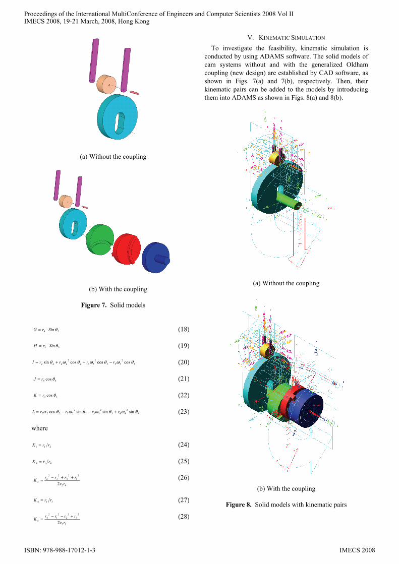
V. KINEMATIC SIMULATION To investigate the feasibility, kinematic simulation is
conducted by using ADAMS software. The solid models of cam systems without and with the generalized Oldham coupling (new design) are established by CAD software, as shown in Figs. 7(a) and 7(b), respectively. Then, their kinematic pairs can be added to the models by introducing them into ADAMS as shown in Figs. 8(a) and 8(b).
(a) Without the coupling
(b) With the coupling
Figure 8. Solid models with kinematic pairs
Proceedings of the International MultiConference of Engineers and Computer Scientists 2008 Vol IIIMECS 2008, 19-21 March, 2008, Hong Kong
ISBN: 978-988-17012-1-3 IMECS 2008
(a) Without the coupling
(b) With the coupling
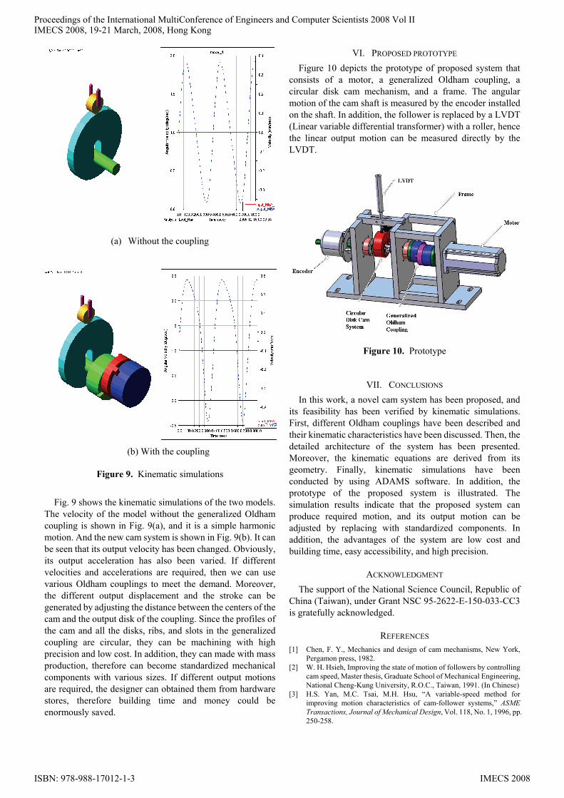
Figure 9. Kinematic simulations
Fig. 9 shows the kinematic simulations of the two models. The velocity of the model without the generalized Oldham coupling is shown in Fig. 9(a), and it is a simple harmonic motion. And the new cam system is shown in Fig. 9(b). It can be seen that its output velocity has been changed. Obviously, its output acceleration has also been varied. If different velocities and accelerations are required, then we can use various Oldham couplings to meet the demand. Moreover, the different output displacement and the stroke can be generated by adjusting the distance between the centers of the cam and the output disk of the coupling. Since the profiles of the cam and all the disks, ribs, and slots in the generalized coupling are circular, they can be machining with high precision and low cost. In addition, they can made with mass production, therefore can become standardized mechanical components with various sizes. If different output motions are required, the designer can obtained them from hardware stores, therefore building time and money could be enormously saved.
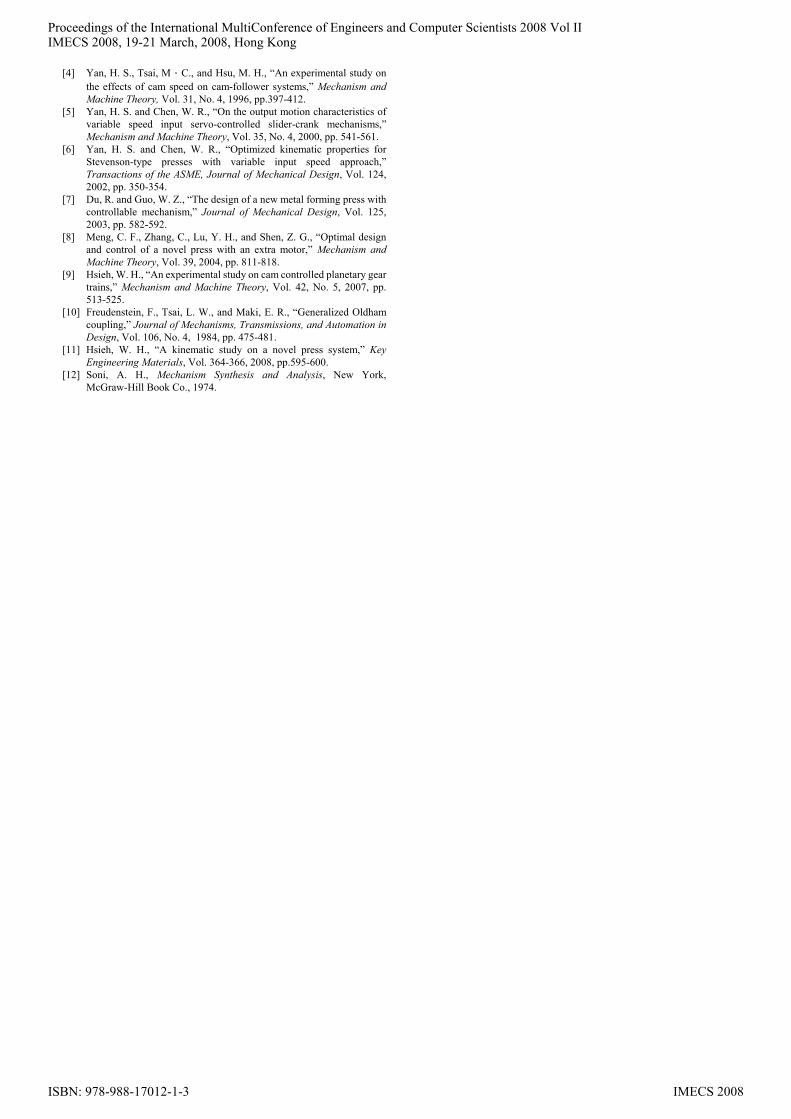
VI. PROPOSED PROTOTYPE Figure 10 depicts the prototype of proposed system that
consists of a motor, a generalized Oldham coupling, a circular disk cam mechanism, and a frame. The angular motion of the cam shaft is measured by the encoder installed on the shaft. In addition, the follower is replaced by a LVDT (Linear variable differential transformer) with a roller, hence the linear output motion can be measured directly by the LVDT.
Figure 10. Prototype
VII. CONCLUSIONS In this work, a novel cam system has been proposed, and
its feasibility has been verified by kinematic simulations. First, different Oldham couplings have been described and their kinematic characteristics have been discussed. Then, the detailed architecture of the system has been presented. Moreover, the kinematic equations are derived from its geometry. Finally, kinematic simulations have been conducted by using ADAMS software. In addition, the prototype of the proposed system is illustrated. The simulation results indicate that the proposed system can produce required motion, and its output motion can be adjusted by replacing with standardized components. In addition, the advantages of the system are low cost and building time, easy accessibility, and high precision.
ACKNOWLEDGMENT The support of the National Science Council, Republic of
China (Taiwan), under Grant NSC 95-2622-E-150-033-CC3 is gratefully acknowledged.
REFERENCES [1] Chen, F. Y., Mechanics and design of cam mechanisms, New York,
Pergamon press, 1982. [2] W. H. Hsieh, Improving the state of motion of followers by controlling
cam speed, Master thesis, Graduate School of Mechanical Engineering, National Cheng-Kung University, R.O.C., Taiwan, 1991. (In Chinese)
[3] H.S. Yan, M.C. Tsai, M.H. Hsu, “A variable-speed method for improving motion characteristics of cam-follower systems,” ASME Transactions, Journal of Mechanical Design, Vol. 118, No. 1, 1996, pp. 250-258.
Proceedings of the International MultiConference of Engineers and Computer Scientists 2008 Vol IIIMECS 2008, 19-21 March, 2008, Hong Kong
ISBN: 978-988-17012-1-3 IMECS 2008
[4] Yan, H. S., Tsai, M.C., and Hsu, M. H., “An experimental study on the effects of cam speed on cam-follower systems,” Mechanism and Machine Theory, Vol. 31, No. 4, 1996, pp.397-412.
[5] Yan, H. S. and Chen, W. R., “On the output motion characteristics of variable speed input servo-controlled slider-crank mechanisms,” Mechanism and Machine Theory, Vol. 35, No. 4, 2000, pp. 541-561.
[6] Yan, H. S. and Chen, W. R., “Optimized kinematic properties for Stevenson-type presses with variable input speed approach,” Transactions of the ASME, Journal of Mechanical Design, Vol. 124, 2002, pp. 350-354.
[7] Du, R. and Guo, W. Z., “The design of a new metal forming press with controllable mechanism,” Journal of Mechanical Design, Vol. 125, 2003, pp. 582-592.
[8] Meng, C. F., Zhang, C., Lu, Y. H., and Shen, Z. G., “Optimal design and control of a novel press with an extra motor,” Mechanism and Machine Theory, Vol. 39, 2004, pp. 811-818.
[9] Hsieh, W. H., “An experimental study on cam controlled planetary gear trains,” Mechanism and Machine Theory, Vol. 42, No. 5, 2007, pp. 513-525.
[10] Freudenstein, F., Tsai, L. W., and Maki, E. R., “Generalized Oldham coupling,” Journal of Mechanisms, Transmissions, and Automation in Design, Vol. 106, No. 4, 1984, pp. 475-481.
[11] Hsieh, W. H., “A kinematic study on a novel press system,” Key Engineering Materials, Vol. 364-366, 2008, pp.595-600.
[12] Soni, A. H., Mechanism Synthesis and Analysis, New York, McGraw-Hill Book Co., 1974.
Proceedings of the International MultiConference of Engineers and Computer Scientists 2008 Vol IIIMECS 2008, 19-21 March, 2008, Hong Kong
ISBN: 978-988-17012-1-3 IMECS 2008