Embed Size (px)
Citation preview

Standardizing the Design of Approach Alignment to Bridges on Forestry Roads in British Columbia: Review and Analysis Date: March 2015
By: Alexander Forrester RPF, EIT
fpinnovations.ca

FPInnovations is a not-for-profit world-
leading R&D institute that specializes in
the creation of scientific solutions in sup-
port of the Canadian forest sector’s global
competitiveness and responds to the
priority needs of its industry members and
government partners. It is ideally posi-
tioned to perform research, innovate, and
deliver state-of-the-art solutions for every
area of the sector’s value chain, from
forest operations to consumer and indus-
trial products. FPInnovations’ staff num-
bers more than 525. Its R&D laboratories
are located in Québec City, Montréal and
Vancouver, and it has technology transfer
offices across Canada. For more infor-
mation
about FPInnovations, visit:
www.fpinnovations.ca.
Follow us on:
© 2015 FPInnovations. All rights reserved. Unauthorized copying or redistribution prohibited.
Disclosure for Commercial Application: If you require assistance to implement these research findings, please contact FPInnovations at [email protected].
301009676: Standardizing the design of
approach alignment to bridges on forestry
roads in British Columbia.
ACKNOWLEDGEMENTS
This project was supported by funding allocated
by the FLNRO Engineering Branch through the
FPInnovations BC Agreement.
The author would like to thank Don Williams,
Allnorth Engineering Consulting; Greg
Honeysett, Caliber Bridge & Design Ltd.;
Lindsey McGill, Chartwell Consultants Ltd.;
Dave Holland, DWB Consulting Services Ltd.;
Chris Grant and Chris Houston, McElhanney;
Michael Foster, Onsite Engineering Ltd.; Lee
Deslauriers and Brad Beaton, StoneCroft
Project Engineering Ltd.; Dick Mynen and
Christina Hutchinson, TDB Consultants Inc.;
Les Thiessen, SNT Engineering Ltd.; Tyson
Miller, Jason Olmsted, Greg Dohm, Paul
Blueschke, and Lyle Unwin, British Columbia
Ministry of Forests, Lands and Natural
Resource Operations; Gary Farnden, Ian
Sturrock, and Darwin Tyacke, British Columbia
Ministry of Transportation and Infastructure.
COVER PHOTO
Main: Tight approach curve to bridge CK-2140
on the West Harrison Lake FSR, Chilliwack
Forest District, British Columbia
REVIEWERS
Brian Chow, P.Eng., Chief Engineer,
Engineering Branch, British Columbia Ministry
of Forests, Lands and Natural Resource
Operations
CONTACT
Alexander Forrester, E.I.T., R.P.F.
Researcher, Resource Roads Group
(604) 222-5655

FPInnovations 3
Table of contents
1. Executive Summary .................................................................................................................... 7
2. Introduction ................................................................................................................................. 8
3. Background ................................................................................................................................. 8
4. Objectives ................................................................................................................................... 9
5. Methodology ............................................................................................................................... 9
Design Vehicles ................................................................................................................................. 9
Long-Load Logging Truck ............................................................................................................. 10
Five-Axle Off-Highway Logging Truck ........................................................................................... 11
WB-19 Tractor Semitrailer ............................................................................................................ 12
WB-20 Tractor Semitrailer ............................................................................................................ 13
Tridem Tractor / Tridem Trailer Low-Bed ...................................................................................... 14
Curve/Tangent Alignment ................................................................................................................. 15
Horizontal ..................................................................................................................................... 15
Minimum Bridge Width .................................................................................................................. 18
Vertical ......................................................................................................................................... 18
6. Results and Discussion ............................................................................................................. 20
Observations from Discussions with FLNRO’s Engineering Groups ................................................. 20
Survey Outcomes ............................................................................................................................. 21
Design Manuals ............................................................................................................................ 21
Design Aids .................................................................................................................................. 21
Typical Design Vehicles ................................................................................................................ 21
Typical Horizontal and Vertical Tangents ...................................................................................... 22
Typical Design Speeds of the Bridge and/or Bridge Approach ...................................................... 22
Analysis ............................................................................................................................................ 23
Horizontal Alignment ..................................................................................................................... 23
Vertical Alignment ......................................................................................................................... 28
Sight Stopping Distance ................................................................................................................ 28
Live Loads .................................................................................................................................... 29
Vehicle Clearance ......................................................................................................................... 30
Alternatives to Typical Bridge Approach Alignment ....................................................................... 32
7. Conclusions .............................................................................................................................. 34
Design Distinctions for the Interior and Coastal Areas of British Columbia .................................... 34
8. Recommendations .................................................................................................................... 35

FPInnovations 4
Bridge Alignment Design .................................................................................................................. 35
Vertical Alignment ......................................................................................................................... 35
Mainline Roads ............................................................................................................................. 35
Secondary Roads ......................................................................................................................... 37
Planning Tools ................................................................................................................................. 39
Professional Responsibility............................................................................................................... 39
Future Works.................................................................................................................................... 39
9. References ................................................................................................................................ 41
10. Appendix A – Survey: Summary of Participants and Responses ............................................... 43
11. Appendix B – Off-Tracking Results ............................................................................................ 46
12. Appendix C – Discussions with FLNRO Engineering Staff: Summary ....................................... 48
FPInnovations 5
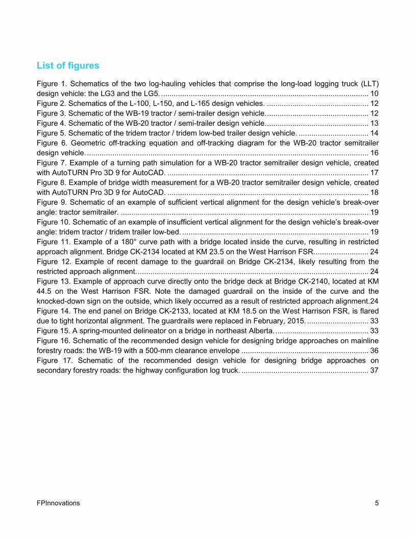
List of figures
Figure 1. Schematics of the two log-hauling vehicles that comprise the long-load logging truck (LLT)
design vehicle: the LG3 and the LG5. .................................................................................................. 10
Figure 2. Schematics of the L-100, L-150, and L-165 design vehicles. ................................................ 12
Figure 3. Schematic of the WB-19 tractor / semi-trailer design vehicle. ................................................ 12
Figure 4. Schematic of the WB-20 tractor / semi-trailer design vehicle. ................................................ 13
Figure 5. Schematic of the tridem tractor / tridem low-bed trailer design vehicle. ................................. 14
Figure 6. Geometric off-tracking equation and off-tracking diagram for the WB-20 tractor semitrailer
design vehicle. ..................................................................................................................................... 16
Figure 7. Example of a turning path simulation for a WB-20 tractor semitrailer design vehicle, created
with AutoTURN Pro 3D 9 for AutoCAD. ............................................................................................... 17
Figure 8. Example of bridge width measurement for a WB-20 tractor semitrailer design vehicle, created
with AutoTURN Pro 3D 9 for AutoCAD. ............................................................................................... 18
Figure 9. Schematic of an example of sufficient vertical alignment for the design vehicle’s break-over
angle: tractor semitrailer. ..................................................................................................................... 19
Figure 10. Schematic of an example of insufficient vertical alignment for the design vehicle’s break-over
angle: tridem tractor / tridem trailer low-bed. ........................................................................................ 19
Figure 11. Example of a 180° curve path with a bridge located inside the curve, resulting in restricted
approach alignment. Bridge CK-2134 located at KM 23.5 on the West Harrison FSR. ......................... 24
Figure 12. Example of recent damage to the guardrail on Bridge CK-2134, likely resulting from the
restricted approach alignment. ............................................................................................................. 24
Figure 13. Example of approach curve directly onto the bridge deck at Bridge CK-2140, located at KM
44.5 on the West Harrison FSR. Note the damaged guardrail on the inside of the curve and the
knocked-down sign on the outside, which likely occurred as a result of restricted approach alignment. 24
Figure 14. The end panel on Bridge CK-2133, located at KM 18.5 on the West Harrison FSR, is flared
due to tight horizontal alignment. The guardrails were replaced in February, 2015. ............................. 33
Figure 15. A spring-mounted delineator on a bridge in northeast Alberta. ............................................ 33
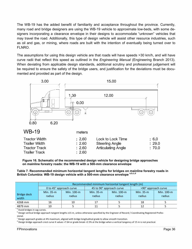
Figure 16. Schematic of the recommended design vehicle for designing bridge approaches on mainline
forestry roads: the WB-19 with a 500-mm clearance envelope ............................................................ 36
Figure 17. Schematic of the recommended design vehicle for designing bridge approaches on
secondary forestry roads: the highway configuration log truck. ............................................................ 37

FPInnovations 6
List of tables
Table 1. Types of design vehicles that survey respondents said they use to design bridges and
alignments on forestry roads ................................................................................................................ 22
Table 2. Minimum horizontal tangent lengths for a range of common bridge approach curves and
design vehicles .................................................................................................................................... 25
Table 3. Minimum bridge widths for a range of common bride approach curves and design vehicles .. 27
Table 4. Minimum curve K values for vertical curves on low-volume roads (British Columbia Ministry of
Transportation and Infrastructure (2007b)a,b ......................................................................................... 29
Table 5. Minimum sight stopping distance for one-lane, two-way bridges (British Columbia Ministry of
Transportation and Infrastructure 1999)a, b, c ......................................................................................... 29
Table 6. Minimum Kvehicle values for design vehicles. ............................................................................ 31
Table 7. Recommended minimum horizontal tangent lengths for bridges on mainline forestry roads in
British Columbia: WB-19 design vehicle with a 500-mm clearance envelope a,b,c,d ............................... 36
Table 8. Recommended horizontal minimum tangent lengths for bridges on secondary forestry roads in
British Columbia: highway configuration design truck a,b,c,d ................................................................... 38

FPInnovations 7
1. EXECUTIVE SUMMARY
FPInnovations was approached in January, 2015, by the Engineering Branch of the British Columbia
Ministry of Forests, Lands and Natural Resource Operations (FLNRO) to assess the state-of-practice of
bridge approach alignment design on forest roads, and to make recommendations for the standardiza-
tion of this process. The lack of uniform standards for the design of forest bridge approach is a concern
because it creates potential safety risks to public and industrial users of resource roads. Further to the
safety implications, inadequate alignment leads to increased risk of damage to bridge structures, costly
repairs and ongoing maintenance. Additionally, forest road user groups, such as oil & gas, B.C. Hydro
and mining, often use specialized transport trucks to haul large equipment that may have different road
alignment requirements than conventional forestry vehicles.
A state-of-practice survey was targeted at forest bridge design engineers, however, FLNRO engineers,
B.C. Ministry of Transportation and Infrastructure (MOTI) engineers and transport truck drivers were
also included. The purpose of this survey was to document current practices for designing bridge ap-
proach alignment on forest roads; the current direction being given by government agencies to forest
bridge design engineers, and the type(s) of design vehicles used for design. Through this survey it was
found that forest road design processes vary throughout the province and, currently, no standard meth-
od or direction is given by government for the design of crossing alignment.
Horizontal and vertical curve requirements for seven design vehicle configurations were assessed and
based on these, recommendations were made for standardizing bridge approach alignment design.
The design vehicle configurations were identified by bridge design engineers, FLNRO and MOTI staff.
Horizontal off-tracking and minimum horizontal tangent requirements were calculated for each design
vehicle using a standard geometric equation and computer software. Next, a geometric equation which
incorporates vehicle clearance and wheel base was used to determine vertical curve limitations of each
vehicle.
Results of the curve assessments were compared with current road design guidelines and codes to
evaluate the applicability of the design vehicles to a forestry setting. It was found that guidance for the
design of bridge approach alignment on forest roads is not clearly established in these documents, and
in some instances conflicts.
Several recommendations were made for the standardization of bridge approach alignment of forest
roads. Due to the diverse nature of forest road networks in B.C., making a single recommendation for
bridge approach alignment was not practical. As a result, recommendations were based on mainline
and secondary roads. Recommendations include a design vehicle, horizontal tangent requirements,
and minimum K values for vertical approach curves. When deviating from these standards, it was rec-
ommended that design engineers include justification as part of the design package.

FPInnovations 8
2. INTRODUCTION
British Columbia’s forestry roads are host to a range of large, heavy, industrial vehicles such as off-
highway logging trucks, fuel tankers, low-beds, rock trucks, graders and heavy construction equipment.
Ensuring these vehicles can safely navigate on and off of bridge structures is important to a safe and
productive forest industry. Approach alignment is a critical component in the design of bridges on for-
estry roads, and is often a limiting factor in bridge location. Approach alignment affects the overall plan-
ning, layout, design, and construction, and has significant effects on user safety, vehicle navigability,
and bridge maintenance costs. FPInnovations was requested by the Engineering Branch of the British
Columbia Ministry of Forests, Lands and Natural Resource Operations to assess current practices for
the design of bridge approach alignment on resource roads, and make recommendations for standard-
izing this process. The assessment, conducted in early 2015, focused on bridge approaches and their
effects on safety, design vehicle selection, and horizontal and vertical tangents. Recommendations for
the future standardization of this process include the selection of design vehicles for various road types,
horizontal and vertical approach alignment, and professional responsibility.
3. BACKGROUND
Due to their industrial purpose, bridges on forestry roads are often two-way, single lane, crossings with
approach alignment designed to a less conservative standard than highway standards (Transportation
Association of Canada 1999, British Columbia Ministry of Transportation 2007a). Section 1.5.1 of the
Can/CSA-S6-06 (Canadian Standards Association 2006) states; “Preference shall be given to straight
horizontal alignments for bridges. The bridge deck longitudinal profile shall be continuous with the ap-
proach road profile.” However, in British Columbia’s rugged and varied terrain it is not always practical
to plan for long horizontal and vertical tangents; geology, site conditions, and economics often result in
roads being narrow and (or) having sharp curves adjacent to bridge structures. In these situations, it is
important that a team of qualified professionals use all relevant planning tools to design a crossing.
Planning tools should account for user safety, design vehicle geometry, and crossing lifespan.
While current design manuals provide some guidance on these subjects, in many parts of the province,
alignment is based solely on experience or site conditions. The resulting use of rules of thumb or best-
fit approaches has led to a lack of design consistency (that is, a mix of approaches and methods are
being used across the province). FLNRO’s Engineering Manual (Engineering Branch 2013) recom-
mends minimal horizontal and vertical tangents of 15 m, while FLNRO (Engineering Branch 1999) rec-
ommends 10 m. The United States Forest Service (2014b) recommends minimum horizontal approach
tangents of 100 ft. (30.5 m) and 50 ft. (15.2 m), depending on road use. Page 2.1.2.37 in the Geometric
Design Guide for Canadian Roads (Transportation Association of Canada 1999) is more applicable to
highway bridges because it specifies approach alignment in context of super elevation, which is not
common when designing forestry roads, and does not provide specific tangent distances. The align-
ment chapter (Section 300) in the BC Supplement to TAC Geometric Design Guide (British Columbia
Ministry of Transportation 2007a) also recommends that bridges be located outside of curves, with an
appropriate tangent but, again, does not specify a tangent distance and, in any case, is referring to
highway bridges. This lack of standardization for designing bridge approaches on forestry roads results
in the potential for unsafe user conditions and increased repair and maintenance costs to bridges
across provincial resource road networks.
FPInnovations 9
Bridge approach design is an iterative process that incorporates detailed field assessments with office-
based analysis and computer-aided design (CAD) to determine the most suitable bridge alignment. For
bridges on forestry roads, the design is typically carried out by a consulting engineer. The design pro-
cess begins with field technicians performing site reconnaissance, layout, and surveys, followed by the
design which is certified by an Engineer of Record. The entire process is managed by a Coordinating
Registered Professional who, depending on scope of practice, is responsible for issuing a crossing as-
surance statement, and ensuring all elements of the crossing design and construction are safe and
comply with current legislation. This process is described in detail in the APEGBC/ABCFP Guidelines
for Professional Services in the Forest Sector—Crossings (2014). In addition to user safety, the Co-
ordinating Registered Professional must also consider values, such as water quality, soil, habitat, and
fish protection, throughout the entire process.
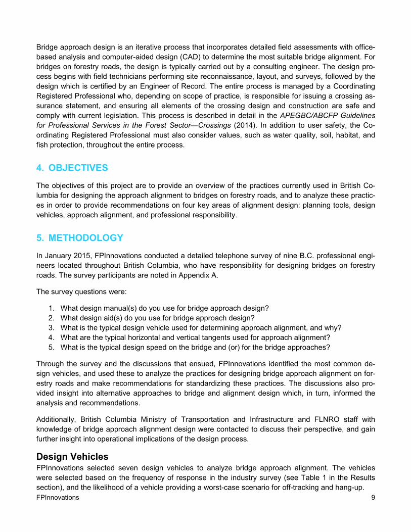
4. OBJECTIVES
The objectives of this project are to provide an overview of the practices currently used in British Co-
lumbia for designing the approach alignment to bridges on forestry roads, and to analyze these practic-
es in order to provide recommendations on four key areas of alignment design: planning tools, design
vehicles, approach alignment, and professional responsibility.
5. METHODOLOGY
In January 2015, FPInnovations conducted a detailed telephone survey of nine B.C. professional engi-
neers located throughout British Columbia, who have responsibility for designing bridges on forestry
roads. The survey participants are noted in Appendix A.
The survey questions were:
1. What design manual(s) do you use for bridge approach design?
2. What design aid(s) do you use for bridge approach design?
3. What is the typical design vehicle used for determining approach alignment, and why?
4. What are the typical horizontal and vertical tangents used for approach alignment?
5. What is the typical design speed on the bridge and (or) for the bridge approaches?
Through the survey and the discussions that ensued, FPInnovations identified the most common de-
sign vehicles, and used these to analyze the practices for designing bridge approach alignment on for-
estry roads and make recommendations for standardizing these practices. The discussions also pro-
vided insight into alternative approaches to bridge and alignment design which, in turn, informed the
analysis and recommendations.
Additionally, British Columbia Ministry of Transportation and Infrastructure and FLNRO staff with
knowledge of bridge approach alignment design were contacted to discuss their perspective, and gain
further insight into operational implications of the design process.
Design Vehicles FPInnovations selected seven design vehicles to analyze bridge approach alignment. The vehicles
were selected based on the frequency of response in the industry survey (see Table 1 in the Results
section), and the likelihood of a vehicle providing a worst-case scenario for off-tracking and hang-up.

FPInnovations 10
Long-Load Logging Truck
The chapter on intersections and access (Section 700) in the BC Supplement to 1999 TAC Geometric
Design Guide (British Columbia Ministry of Transportation 2007c), specifies the long-load logging truck
(LLT) as a combination of two design vehicles that “effectively addresses the path requirements for all
currently permitted Long-load Logging Trucks in BC.”
The LLT combines two vehicles, an LG3 and an LG5 (Figure 1), so that it is possible to simulate at one
time the greatest possible sweep (LG3) and the greatest possible off-tracking (LG5) of logging trucks.
The LLT is typically used for intersection design; however, it was included in FPInnovations’ analysis as
a design vehicle for bridge approach assessment because it addresses the path requirements for all
currently permitted LLTs in British Columbia (British Columbia Ministry of Transportation 2007c).
Figure 1. Schematics of the two log-hauling vehicles that comprise the long-load
logging truck (LLT) design vehicle: the LG3 and the LG5.

FPInnovations 11
Five-Axle Off-Highway Logging Truck
The Engineering Manual (Engineering Branch 2013) depicts several 5-axle off-highway logging trucks
for bridge loading design purposes: the L-100, L-150, and L-165. FPInnovations used all three L series
vehicles in the analysis of off-tracking and horizontal tangent requirements.
The five-axle off-highway logging vehicle was assumed to be a tandem tractor / pole trailer configura-
tion with an overall length of 23 m (including load). A 3-m front overhang of the load was included, while
the rear overhang was variable (Figure 2). Note, the Standard Drawings for the Bridge Design & Con-
struction Manual (Henley 2013) does not provide full dimensions for these vehicles. Therefore, tractor
dimensions were based on a Pacific P-16 off-highway tractor, with wheelbase and axle-width dimen-
sions based on the standard drawings.

FPInnovations 12
WB-19 Tractor Semitrailer
In the Geometric Design Guide for Canadian Roads (Transportation Association of Canada 1999) the
WB-19 tractor semitrailer is specified as a design envelope vehicle used for designing roads, intersec-
tions, and site access characteristics (Figure 3). It has a tractor wheelbase of 6.2 m, a trailer wheelbase
of 12 m, an overall length of 20.7 m, and a minimum turning radius of 10.7 m (outside front wheel)
through a 90° curve path. Additionally, the WB-19 can represent flat-deck trailer combinations, which
are used to transport forestry materials, supplies, and equipment during harvesting operations.
Figure 2. Schematics of the L-100, L-150, and L-165 design vehicles.
Figure 3. Schematic of the WB-19 tractor / semi-trailer design vehicle.

FPInnovations 13
WB-20 Tractor Semitrailer
The WB-20 tractor semi-trailer design envelope vehicle (Transportation Association of Canada 1999)
(Figure 4) is similar to the WB-19 (Figure 3), except that the WB-20 has a trailer wheelbase 2.0 m long-
er than the WB-19 for a total trailer wheelbase of 12.4 m.
The WB-20 has an overall length of 22.7 m, with a minimum turning radius of 10.7 m (outside front
wheel). The longer wheelbase and overall length of this vehicle make it a good candidate for analyzing
off-tracking and the minimum required horizontal approach tangent for bridges on forest roads. Like the
WB-19, this vehicle can represent flat-deck trailer configurations that service harvesting operations.
Figure 4. Schematic of the WB-20 tractor / semi-trailer design vehicle.
FPInnovations 14
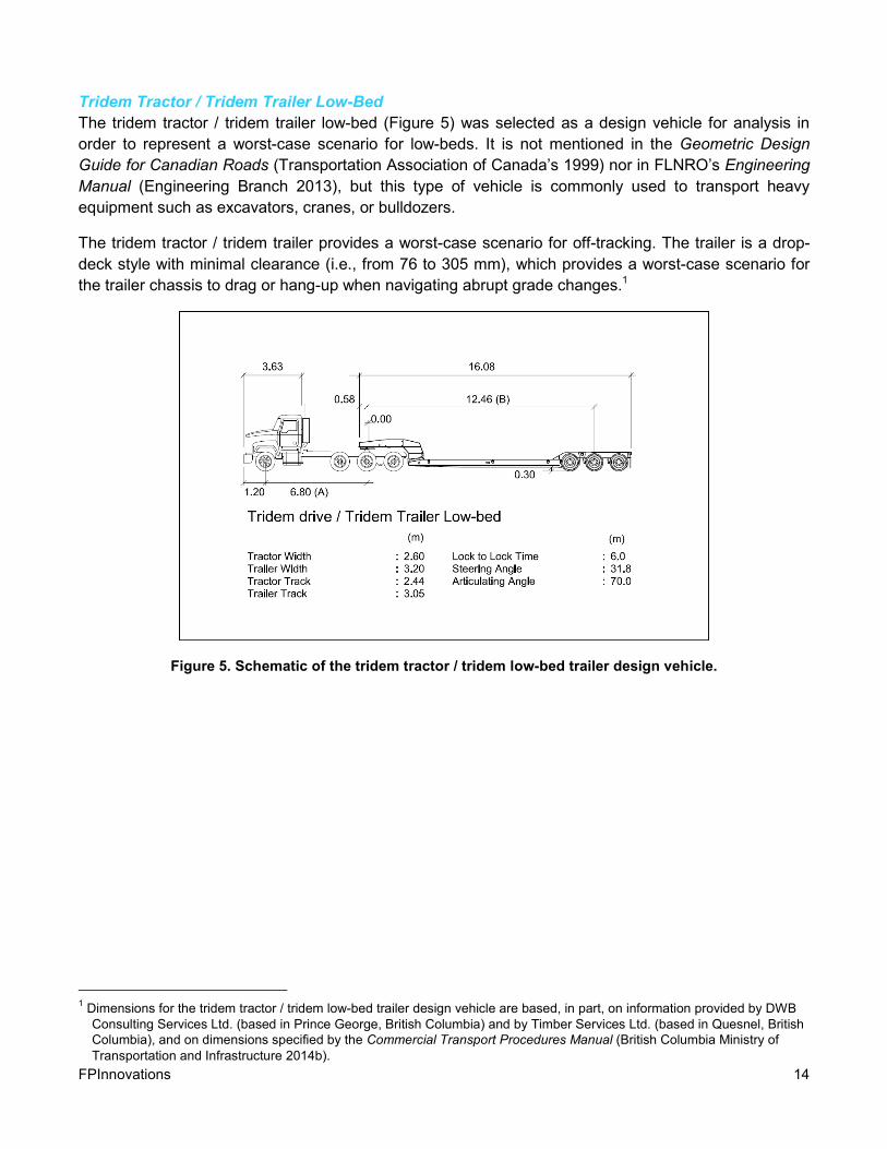
Tridem Tractor / Tridem Trailer Low-Bed
The tridem tractor / tridem trailer low-bed (Figure 5) was selected as a design vehicle for analysis in
order to represent a worst-case scenario for low-beds. It is not mentioned in the Geometric Design
Guide for Canadian Roads (Transportation Association of Canada’s 1999) nor in FLNRO’s Engineering
Manual (Engineering Branch 2013), but this type of vehicle is commonly used to transport heavy
equipment such as excavators, cranes, or bulldozers.
The tridem tractor / tridem trailer provides a worst-case scenario for off-tracking. The trailer is a drop-
deck style with minimal clearance (i.e., from 76 to 305 mm), which provides a worst-case scenario for
the trailer chassis to drag or hang-up when navigating abrupt grade changes.1
Figure 5. Schematic of the tridem tractor / tridem low-bed trailer design vehicle.
1 Dimensions for the tridem tractor / tridem low-bed trailer design vehicle are based, in part, on information provided by DWB
Consulting Services Ltd. (based in Prince George, British Columbia) and by Timber Services Ltd. (based in Quesnel, British
Columbia), and on dimensions specified by the Commercial Transport Procedures Manual (British Columbia Ministry of
Transportation and Infrastructure 2014b).

FPInnovations 15
Curve/Tangent Alignment For each of the design vehicles identified through the survey, FPInnovations evaluated how the vehicle
navigated two different bridge deck widths based on various approach curve radii (Table 2). The pur-
pose of the analysis was to determine minimum required horizontal approach tangents for each vehicle.
Vertical alignment was assessed based on vehicle characteristics and standardized parabolic curve
processes for the design of bridge approach alignment. Additionally, an evaluation of the minimum re-
quired bridge width was performed based on the 10 m and 15 m horizontal tangents (Table 3) specified
in the Engineering Manual (Engineering Branch 2013) and FLNRO (Engineering Branch 1999).
Horizontal
FPInnovations assessed off-tracking of the design vehicles, both geometrically and through AutoTURN
simulations (Appendix B). The purpose of this was to determine if current road-widening tables in the
Engineering Manual (Engineering Branch 2013) are adequate, and to gauge which design vehicle
would provide a worst-case scenario for tracking on and off of a bridge. FPInnovations used the follow-
ing equation to calculate the geometric off-tracking for each of the design vehicles (Figure 6): and to
reveal which vehicle exhibited the most significant off-tracking:
����������� � = � − √�� − �� × �1 − ����.���∆� !"#$�.��%&� where,
∆'()= *����+� ,�,
� = -,�.���/�,0, and
� = 1�ℎ��3�4������.����ℎ = ∑ �6�768� .
The hypothesis was that the vehicle with the worst off-tracking would require the longest horizontal tan-
gent to safely manoeuvre on and off a bridge. The off-tracking equation takes into consideration curve
radius, degree of turn, tractor wheelbase, and wheelbases of all trailers including hitch offsets. Also,
using AutoTURN Pro 3D 9 for AutoCAD, FPInnovations simulated and measured the off-tracking of
each design vehicle. The results were compared to the geometric calculation results.

FPInnovations 16
����������� � = � − 9�� − �� × �1 − ����.���∆� !:;$�.��%&� where,
∆'()= *����+� ,�, � = -,�.���/�,0, �/
� = 1�ℎ��3�4������.����ℎ = =�6�7
68�.
Using AutoTURN, minimum horizontal tangents were calculated for each design vehicle by simulating
various turning paths (Figure 7). Twenty-four horizontal curve paths were simulated for each design
vehicle; which included turns of 45°, 90°, 135° and 180° for 15-m, 35-m, and 100-m curve radii. The
curve radii reflect design specifications presented in Table 3-2 “Summary of Alignment Controls for
Forest Roads” in FLNRO’s Engineering Manual (Engineering Branch 2013). Bridge deck widths used in
the simulation were 4268 mm and 4876 mm, as per the widths outlined in the Standard Drawings for
the Bridge Design & Construction Manual (Henley 2013). An additional 400-mm offset from the guard-
rails was included because this is a requirement outlined in FLNRO standard drawings STD-EC-000-01
and 02 (Henley 2013). The offset distance is measured from the guardrail to the centerline of the out-
side-of-curve steering tire and the inside-of-curve rear trailer tire. The guardrail is assumed to be 150
mm outside of the bridge deck, measured from the edge of bridge deck, which is common because
most guardrails are attached outside of the bridge deck by steel or wooden brackets (STD-EC-010-01
to 05 in Henley 2013).
The minimum required horizontal tangents were determined through 2D simulations using AutoTURN.
Tangents were determined by measuring the distance from the end of the curve to where the design
vehicle started to clear the guardrail (Figure 7). For modelling purposes, the bridge deck was simulated
by lines offset from the road centreline, corresponding to the two bridge deck widths (4268 mm and
Figure 6. Geometric off-tracking equation and off-tracking diagram for the WB-20 tractor semitrailer design vehicle.
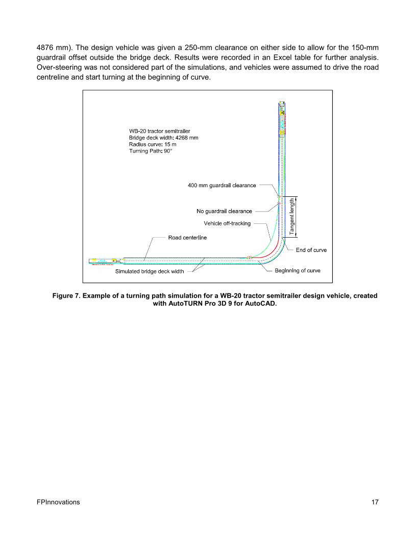
FPInnovations 17
4876 mm). The design vehicle was given a 250-mm clearance on either side to allow for the 150-mm
guardrail offset outside the bridge deck. Results were recorded in an Excel table for further analysis.
Over-steering was not considered part of the simulations, and vehicles were assumed to drive the road
centreline and start turning at the beginning of curve.
Figure 7. Example of a turning path simulation for a WB-20 tractor semitrailer design vehicle, created with AutoTURN Pro 3D 9 for AutoCAD.

FPInnovations 18
Minimum Bridge Width
To provide another perspective on forest bridge approach design, analysis using 10 m and 15 m hori-
zontal approach tangents was done to evaluate the minimum required bridge width for each design
vehicle identified in the survey. AutoTURN was used to simulate each design vehicle navigating a 15
m, 35 m and 100 m radii curve for 45°, 90°, 135° and 180° curve paths. 10 m and 15 m horizontal tan-
gents were marked on the simulation following the end of the curve. A 400 mm envelope was applied to
each vehicle. The required bridge width was measured at the end of the tangent and included the 400
mm buffer (Figure 8).
Figure 8. Example of bridge width measurement for a WB-20 tractor semitrailer design vehicle, created with AutoTURN Pro 3D 9 for AutoCAD.
Vertical
For determining vertical alignment, the break-over angle2 of the tractor and trailer (Figure 9) was de-
termined and compared to recommended design K values (British Columbia Ministry of Transportation
2007b).
Using the break-over angle, a minimum K value for each design vehicle (Kvehicle) was determined. The K
value is a parabolic function of the total horizontal curve length, and change in grade. The higher the
value of K is, the less abrupt the curve. Kvehicle is determined by modifying the K value equation Eq.
2.1.23 in the Geometric Design Guide for Canadian Roads (Transportation Association of Canada
1999) to assume the horizontal length of the curve is equal to the wheelbase of the design vehicle.
2 The break-over angle is the maximum angular difference (degrees), or grade break (%), that a vehicle can safely navigate
without hanging up (i.e., without its chassis contacting the bridge or road surface).

FPInnovations 19
When Kvehicle > Kdesign there is a high likelihood of vehicle hang-up, resulting in unsafe conditions, and
lost productivity (Figure 10)
>����+.���3� = 2 × tan�� C2 × �+,/�3������Dℎ��3E�0� F
GH(I6JK( = Dℎ��3E�0�100 × tan�E����+.���3��
Figure 9. Schematic of an example of sufficient vertical alignment for the design vehicle’s break-over angle: tractor semitrailer.
Figure 10. Schematic of an example of insufficient vertical alignment for the design vehicle’s break-over angle: tridem tractor / tridem trailer low-bed.

FPInnovations 20
6. RESULTS AND DISCUSSION
Observations from Discussions with FLNRO’s Engineering Groups FPInnovations’ discussions with FLNRO Engineering Branch staff around the province provided insight
to the process of bridge alignment design relative to implementation of the design in the field. The dis-
cussions are summarized in Appendix C.
The discussions revealed that often the consulting design engineer, does not actually see the complet-
ed bridge in daily operation, meanwhile FLNRO engineering staff are responsible for ensuring cross-
ings are maintained in a safe condition. The disconnect between design and operations can lead to a
variety of serious issues related to safety, repairs, and maintenance, and even to the need to re-design
or replace the bridge.
The Southern Engineering Group, based In Kamloops, often specifies a WB-19 design vehicle, with
500-mm of clearance on either side. This design vehicle was specified following measurement of sev-
eral low-beds that frequent forest roads in the southern region (Appendix C). Based on this, the group
determined that the WB-19 represents the majority of vehicle dimensions travelling the roads in their
region. Additionally, it was discussed that the 500-mm clearance allows other stakeholders—such as
BC Hydro and the oil and gas industry, who do use the roads but not frequently—to bring in larger con-
figuration loads. Vertical alignment is also an issue, with break-over angles often being insufficient for
the crossing. An example of this is a bridge that had a crest curve grade break at the bridge of 10.5%,
which resulted in low-beds becoming hung up on the crest. In general, the Group felt that having mini-
mum standards would mitigate the issues they are seeing, and act as an opportunity to educate design
engineers to think critically about approach alignment.
The Southern Engineering Group also noted that more bridges include pedestrian handrails. These
handrails are higher than traditional timber guardrails. Historically, wide vehicles could drive onto the
bridge with the load overhanging the low guardrails, but the higher guardrails have made this impracti-
cal and have resulted in damage to several bridges.
The Northern Engineering Group, based in Prince George, typically relies on professional judgement in
regards to horizontal and vertical alignment. Recommendations from staff to designers include using
the 15-m horizontal and vertical tangents specified in the Engineering Manual (Engineering Branch
2013), but do not specify a vehicle for off-tracking purposes. When designers deviate from the Manual’s
tangents, they are expected to provide documentation and justification for their decisions. Typically,
tracking is more of a concern on mainline roads frequented by low-beds and similar vehicles. Currently
there is a push from industry to allow longer off-highway haul trucks, carrying larger loads, on the roads
because there is a shortage of drivers in the region. The larger loads help maintain sufficient timber
volume delivery to mills despite the driver shortage; however, there is concern from the Group that
longer trucks may have issues with existing bridge approach alignments. Bridge approach alignment on
secondary roads is not a significant concern in the region because off-highway trucks can often navi-
gate tight alignment, and the short lifespan of these crossings allows for a higher level of risk ac-
ceptance.
The Coastal Engineering Group, based in Nanaimo, provides bridge approach alignment criteria to
consulting design engineers. However, it is recognized that steep terrain often requires the design of
bridges and approaches to be innovative. When constructing mainlines or providing permanent access
FPInnovations 21
to communities or high-value recreation, a WB-19 design vehicle is specified with a 300 to 500-mm
clearance depending on the site. Similar to the Southern Engineering Group, the WB-19 was decided
upon following measurement of several “fat” off-highway configuration logging trucks that are commonly
used on northern Vancouver Island (Appendix C). The 500-mm clearance ensures these “fat” trucks
can safely navigate on and off of bridges. For secondary access, depending on highway or off-highway
configurations, the BCL-625 or an L series design truck is specified. FLNRO engineering staff specify
the use of 10-m horizontal and vertical tangents as described in the Forest Service Bridge Design and
Construction Manual (Engineering Branch 1999); however, site conditions may require a deviation from
this practice. Often a minimum 7-m horizontal tangent is designed in combination with flared end panels
to provide additional horizontal clearance. Vertical curve K values for bridge approaches are specified
at 12 for crests and 13 for sags; these values have a long history of use in this region, and to date have
proven adequate.
Survey Outcomes The survey participants provided a range of responses, and all responses were considered. The survey
questions often led to in-depth discussions with the respondents. Often the respondent considered ap-
proach design to be a site-specific process; this led to survey participants giving multi-part responses
based on road use (e.g., in-block vs. mainline roads). The responses are summarized in Appendix A.
Design Manuals
All nine respondents use the FLNRO’s Engineering Manual (Engineering Branch 2013) and Forest Ser-
vice Bridge Design and Construction Manual (Engineering Branch 1999). Two designers also use the
Geometric Design Guide for Canadian Roads (Transportation Association of Canada 1999) as a sup-
plement. All three of these manuals discuss approach tangents, although they provide limited details.
Through follow-up conversations with respondents, FPInnovations discovered that most designers use
the design manuals only as guidelines and they typically design bridge approaches based on site con-
ditions. In regions with steep topography, approach alignment is designed on the basis of best fit to the
terrain and conditions; modifications to the bridge deck width (enlargement or flaring) and/or an ac-
ceptance of significant maintenance and repair costs are common.
Design Aids
Most design engineers surveyed use a version of AutoTURN, with one respondent using the British
Columbia Ministry of Transportation and Infrastructure’s PathTracker software.
Both of these programs calculate off-tracking of a vehicle based on dimensions and curve specifica-
tions that are input by the user. Both programs are useful in ensuring the approach alignment is safe for
the bridge/road user, and that collisions between the design vehicle and bridge will not occur. However,
some respondents believe software programs are too conservative in their solutions, and that during
construction the alignment can be shortened to better fit the site and to reduce costs. These are im-
portant observations, as first-hand construction experience can often provide practical solutions that
office-based analysis does not.
Typical Design Vehicles
Several design vehicles, both on-highway and off-highway, were reported (Table 1). Respondents often
employ a range of design vehicles, depending on the situation. For the purpose of analysis and discus-
sion here, FPInnovations placed the vehicles into three categories: 5-axle off-highway logging trucks (L-

FPInnovations 22
100 and L-165), tractor/semitrailer combinations (WB-15, WB-18, WB-19, and WB-20), and low-beds
(respondent-defined dimensions).
Respondents said they commonly select a design vehicle that approximates low-bed off-tracking, be-
cause this is considered the most limiting design condition for bridge approaches (Appendix A). There
were variations on this theme, with some designers using the WB series vehicles, while others choose
a low-bed based on known dimensions (e.g., a tridem tractor/ tridem trailer low-bed). The L series off-
highway logging trucks are more commonly used for bridge load design; however, the dimensions can
be used to design bridge approaches for in-block roads, i.e., where a higher level of risk (in terms of
damage to the structure or signs) is acceptable and heavy equipment is expected to “walk” the road as
opposed to being delivered on a low-bed. Based on survey results, the WB-19 was the most common
vehicle used for the purposes of bridge approach design (Table 1).
Table 1. Types of design vehicles that survey respondents said they use to design bridges and align-ments on forestry roads
Type of design vehicle
Respondents using this vehicle
(no.)
5-axle off-highway design truck (L series vehicles) L-165 2 L-100 1
Tractor / semitrailer combinations (WB series vehicles) WB-15 1 WB-18 1 WB-19 4 WB-20 1
Tractor / low-bed trailer Tridem tractor / tridem trailer 1 Configuration not specified 2
Typical Horizontal and Vertical Tangents
Respondents said that horizontal tangents range from 30 m long to “whatever fits”. Vertical tangents
range from 5 to 10 m long but are consistently less than the horizontal tangents. Two respondents did
not give specific values, because they believe that each bridge approach has different challenges and,
therefore, they specify a tangent length based on site conditions and economics.
Typical Design Speeds of the Bridge and/or Bridge Approach
Respondents said that design speed depends on road class: traffic is assumed to travel at 20 km/h on
spur roads, 30 km/h on access roads, and 50 km/h on mainlines. Typically, designers base horizontal
and vertical curve alignment on Table 3-2 “Summary of alignment controls for forestry roads” in the
Engineering Manual (Engineering Branch 2013), which establishes alignment controls and minimum
curve radii for various road speeds and widths. In general, speed was found to be a function of the road
and not the bridge approach unless site-specific conditions required a reduced speed.

FPInnovations 23
Analysis
Horizontal Alignment
Vehicle off-tracking
In all scenarios, the tridem tractor / tridem trailer low-bed showed the most significant off-tracking. In the
case of a 15-m radius curve, the geometric method of solving off-tracking gave a minimum subgrade
width of 10.18 m, which is greater than the 9-m minimum specified in the Engineering Manual (Engi-
neering Branch 2013) (Appendix B).
Not all forestry roads are the same, and a one-size-fits-all approach to curve widening is not practical.
Typically, mainline forestry roads are constructed to accommodate significant traffic loads, and they
have straighter alignment and higher travel speeds than secondary roads. Addressing off-tracking on
mainline roads is critical to user safety because corners or bridge approaches are travelled at speeds
≥50 km/h. The recommended minimum curve radius is 100 m for roads with a 50 km/h design speed
(Engineering Branch 2013). With this size of curve, vehicle off-tracking is minimized; however, higher
travel speeds do increase user risk. It should be noted that mainline roads may have significant levels
of public traffic; in these cases, designers need to consider more conservative curve designs to ensure
user safety. Secondary roads, i.e., either in-block or end-of-system roads, serve the specific purposes
of accessing harvest units for a defined period of time, and possibly for providing subsequent periodic
access. Often, they are steep and narrow with tight curves and poor visibility. Excessive curve widening
in these conditions may not be practical and efficient (i.e., the steep slopes would result in significant
sidecast or expensive end hauling). In these situations, it is more practical to determine what type of
vehicles will be accessing the blocks and then use this information to create an efficient road design.
Horizontal tangents
Table 2 summarizes the results of an analysis of four curves and seven design vehicles (Figures 1 to
5). As expected, the tridem tractor / tridem trailer low-bed produced the greatest required horizontal
tangent for all turning scenarios.
These results indicate that current recommendations regarding horizontal tangents may not be ade-
quate for construction support vehicles and other industrial road user demands (e.g., oil and gas, min-
ing, large-scale licensees, etc.). While some of the turning scenarios may be rare for bridge approaches
(i.e., 15 m radius, 180° curve onto a bridge), these situations do arise in terrain with deeply incised gul-
lies (Figures 11, 12, and 13), and when accessing steep slopes where switchbacks are required for
elevation gain. Therefore, it is important to note that curves may sometimes need a longer transition
than is currently specified in the Engineering Manual (Engineering Branch 2013).

FPInnovations Page 24
Figure 11. Example of a 180° curve path with a bridge located inside the curve, resulting in restricted approach alignment. Bridge CK-2134 located at KM 23.5 on the West Harrison FSR.
.
Figure 12. Example of recent damage to the guardrail on Bridge CK-2134, likely resulting from the restricted approach alignment.
Figure 13. Example of approach curve directly onto the bridge deck at Bridge CK-2140, located at KM 44.5 on the West Harrison FSR. Note the damaged guardrail on the inside of the curve and the knocked-down sign on the outside, which likely occurred as a result of restricted approach alignment.
Damaged guardrail
Knocked-down sign

FPInnovations Page 25
Table 2. Minimum horizontal tangent lengths for a range of common bridge approach curves and design vehicles
Design
vehicle
Bridge deck
width (mm)
Minimum horizontal tangent length (m) b
45° approach curve 90° approach curve 135° approach curve 180° approach curve
15-m radi-
us curve
35-m radi-
us curve
100-m
radius
curve
15-m radi-
us curve
35-m radi-
us curve
100-m
radius
curve
15-m radi-
us curve
35-m radi-
us curve
100-m
radius
curve
15-m radi-
us curve
35-m radi-
us curve
100-m
radius
curve
Long-load Logging Truck (LLT)
LLT 4269 11.27 5.71 1.96 13.54 6.18 n/a 14.06 6.11 n/a 14.42 6.17 n/a
4877 7.67 2.04 n/a 10.12 2.72 n/a 10.67 2.49 n/a 10.81 2.51 n/a
5-axle off-highway logging truck (L series)
L-100 4269 12.15 7.02 4.43 13.72 7.35 n/a 14.17 7.30 n/a 14.47 7.35 n/a
4877 6.83 1.60 n/a 8.48 1.91 n/a 8.95 1.87 n/a 8.99 1.93 n/a
L-150 4269 12.16 7.04 4.42 13.73 7.35 n/a 14.51 7.30 n/a 14.64 7.36 n/a
4877 6.82 1.60 n/a 8.46 1.93 n/a 8.96 1.90 n/a 9.00 1.91 n/a
L-165 4269 11.29 6.27 3.87 12.67 6.53 n/a 13.19 6.48 n/a 13.29 6.55 n/a
4877 6.17 1.05 n/a 7.64 1.36 n/a 8.05 1.30 n/a 8.06 1.33 n/a
Tractor/semitrailer combinations (WB series vehicles)
WB-19 4269 19.09 12.85 6.90 23.72 14.32 1.19 25.75 14.38 2.06 26.68 14.50 1.22
4877 13.99 7.73 1.74 18.66 9.23 n/a 20.70 9.37 n/a 21.63 9.44 n/a
WB-20 4269 20.68 14.55 7.65 25.79 15.97 1.92 27.99 15.59 2.77 28.83 15.67 1.95
4877 15.42 9.10 2.34 20.59 10.72 n/a 22.78 10.33 n/a 23.60 10.42 n/a
Tractor / low-bed trailer
Tridem /
tridem
low-bed
4269 29.92 23.60 17.46 34.90 25.26 11.72 37.12 25.43 12.58 38.22 25.50 11.75
4877 20.74 14.41 8.19 25.77 16.11 2.43 28.03 16.23 3.27 29.11 16.31 2.43
a Values assume that a 400-mm buffer from guardrail is maintained.
b Curve radius and speed limits as per FLNRO’s Engineering Manual (Table 3-2 in Engineering Branch 2013).

FPInnovations Page 26
Minimum Bridge Widths
Table 3 summarizes the results of evaluating minimum required bridge widths for each design vehicle.
It was found that smaller curve radii and larger curve paths required wider bridge widths. This was
common for all AutoTURN simulations.
FLNRO standard bridge deck widths are specified to be 4269 mm and 4877 mm wide, with guardrails
typically mounted to the outside of the bridge deck. 168 AutoTURN simulations were performed using
the various vehicle configurations, curve radii, curve paths and standard approach tangents. Of the
results 89 indicated that a bridge width of 4269 was too narrow, and for 42, a bridge width of 4877 mm
was too narrow. As would be expected, the severity increases with smaller curve radius and degree of
approach road curve. This illustrates the importance of applying higher level engineering and the value
of identifying standard vehicle configurations for bridge approach road design. It is suggested that
FLNRO undertake a review of its standards for bridge deck widths in concert with bridge approach road
tangent lengths.

FPInnovations Page 27
Table 3. Minimum bridge widths for a range of common bride approach curves and design vehicles
Design
vehicle
Tangent
Length (m)
Minimum Bridge Width (m) a
45° approach curve 90° approach curve 135° approach curve 180° approach curve
15-m radi-
us curve
35-m radi-
us curve
100-m
radius
curve
15-m radi-
us curve
35-m radi-
us curve
100-m
radius
curve
15-m radi-
us curve
35-m radi-
us curve
100-m
radius
curve
15-m radi-
us curve
35-m radi-
us curve
100-m
radius
curve
Long-load Logging Truck (LLT)
LLT 10 4.42 3.98 3.75 4.80 4.02 3.62 4.97 4.02 3.63 5.02 4.02 3.62
15 4.05 3.76 3.63 4.27 3.78 3.53 4.37 3.77 3.54 4.40 3.78 3.53
5-axle off-highway logging truck (L series)
L-100 10 4.67 4.36 4.24 4.87 4.38 4.13 4.92 4.38 4.14 4.95 4.38 4.13
15 4.39 4.20 4.14 4.48 4.21 4.07 4.52 4.21 4.08 4.52 4.21 4.07
L-150 10 4.68 4.36 4.24 4.86 4.37 4.13 4.93 4.37 4.14 4.94 4.37 4.35
15 4.38 4.20 4.14 4.49 4.21 4.07 4.52 4.21 4.08 4.53 4.21 4.07
L-165 10 4.61 4.32 4.22 4.76 4.33 4.12 4.82 4.33 4.13 4.82 4.34 4.12
15 4.33 4.71 4.12 4.42 4.18 4.06 4.44 4.18 4.07 4.45 4.18 4.06
Tractor/semitrailer combinations (WB series vehicles)
WB-19 10 4.71 4.22 3.90 5.36 4.34 3.73 5.74 4.36 3.75 5.93 4.36 3.73
15 4.33 3.98 3.75 4.78 4.06 3.63 5.04 4.06 3.64 5.16 4.07 3.63
WB-20 10 4.80 4.28 3.93 5.51 4.42 3.75 5.93 4.44 3.77 6.19 4.44 3.76
15 4.40 4.03 3.78 4.88 4.12 3.65 5.18 4.12 3.67 5.34 4.12 3.65
Tractor / low-bed trailer
Tridem /
tridem
low-bed
10 5.22 4.77 4.46 5.91 4.90 4.32 6.34 4.91 4.34 6.58 4.92 4.32
15 4.88 4.56 4.34 5.33 4.64 4.22 5.59 4.65 4.24 5.83 4.65 4.22
a Values include a 400-mm buffer from the guardrails.
FPInnovations Page 28
Vertical Alignment
The proper design of the vertical alignment of bridge approaches is critical to user safety and bridge
lifespan. Sudden grade changes may reduce driver visibility, cause vehicle clearance issues, and in-
crease live loading on the structure.
FLNRO typically recommends that bridge structures have a relatively flat longitudinal grade that is ver-
tically aligned with the approach tangents. Both the FLNRO’s Engineering Manual (Engineering Branch
2013) and the Forest Service Handbook (United States Forest Service 2014a,b) recommend bridge
decks be no steeper than 4% and aligned with approach tangents, while the chapter on alignment (Sec-
tion 300) in the BC Supplement to TAC Geometric Design Guide (British Columbia Ministry of Trans-
portation 2007a) recommends bridge decks be no steeper than 2% and aligned with approach tangents
(Table 3). These grades promote drainage across the structure and reduce the potential for ponding;
smooth transitions increase user safety, decrease live loading, and mitigate clearance issues.
When discussing vertical alignment, tangency is not the only consideration. Sight stopping distance,
approach curve K values, and grade break are also important; and, approach curve K values and grade
break may provide alternatives to long vertical approach tangents. For example, in situations where
terrain restricts the vertical tangent length, if the designer ensures the vertical approach curves do not
exceed the Kvehicle or vehicle break-over angle for the worst-case scenario vehicle, then this performs
the same function as using an adequate vertical approach tangent. It should be noted that the designs
of the horizontal and vertical approach alignments are not exclusive of each other, and the design pro-
cess must consider both to ensure an optimal design.
Sight Stopping Distance
Sight stopping distance is an issue for both crest and sag curves. However, in the context of approach-
es to bridges on forestry roads, the issue is largely mitigated by the roads’ radio call procedures, slower
travel speeds, and vegetation clearing along the road right-of-way. But on forestry roads frequently
travelled by the public, the design of vertical curves should follow the standards in the low-volume
roads chapter (Section 500) of the BC Supplement to TAC Geometric Design Guide (British Columbia
Ministry of Transportation 2007b) (Table 4) and the Geometric Design Guide for Canadian Roads
(Transportation Association of Canada 1999) (Table 5), because of the added risk created by fast-
moving public vehicles whose drivers are likely unfamiliar with industrial road use and the constraints of
driving on gravel surfaces.

FPInnovations Page 29
Table 4. Minimum curve K values for vertical curves on low-volume roads (British Columbia Ministry of Transportation and Infrastructure (2007b)
a,b
Design speed (km/h)
Minimum sight stopping distance
(m)
Minimum curve K value
Sag a
Crest b
30 30 4 3
40 45 7 5
50 65 12 11
60 85 17 18
70 110 24 30
80 140 32 50
90 170 40 90 a Sag vertical curves design for sight stopping distance using headlight control criteria of 0.6 m above
road surface with 1° upward angle. b
Crest vertical curves design for sight stopping distance using 1.05-m driver eye height and 150-mm fixed object height.
Table 5. Minimum sight stopping distance for one-lane, two-way bridges (British Columbia Ministry of Transportation and Infrastructure 1999)
a, b, c
Operating speed (km/h)
Minimum stopping sight distance (m)
On two-way roads On one-lane, two-way bridges c
30 30 30 + L + F1 + F2
40 45 45 + L + F1 + F2
50 65 65 + L + F1 + F2 a Bridges are not designed in sag curves.
b L = span distance. F1 & F2 = flare distance at bridge ends.
c Crest curve K (one-lane, two-way bridges) K = SD2
398.745
Live Loads
Excessive live loading caused by poor vertical approach alignment may, over time, cause a structure to
fatigue or fail, and will likely increase overall maintenance costs due to frequent repairs. Live loads are
imposed by vehicles, pedestrians, equipment, or any components that are subject to movement. When
designing bridges on national highways a CL-W truck is used to account for live loading. Other factors
taken into consideration are vehicle count, multi-lane loading, and dynamic load allowance (Canadian
Standards Association 2006). For bridges on forestry roads, live loading is based on the BCL-625, L-
100, L-150, or L-165 design vehicles. It is assumed that vehicles cross one at a time, down the centre
of the bridge (Engineering Branch 2013).
A smooth transition from the roadway to the bridge deck ensures live loads are consistent with design,
and that no unnecessary “punching out” or “slamming” onto the bridge occurs. These conditions typical-
ly occur on sag curves where poor alignment causes an abrupt transition from the road to the bridge.
Sag curves transition the road grade from a downward trajectory to a more upward one; the change in

FPInnovations Page 30
trajectory causes an acceleration perpendicular to the centre of the curve. As a result, the vehicle trav-
elling the sag curve exerts an increased downward force onto the roadway or bridge deck. This can be
felt by the driver and is referred to as g-force. The effects of this increased load can potentially cause
abutment failure and/or structure failure; and/or vehicle and bridge deck damage can occur, caused by
the vehicle bottoming out. Due to these excessive loads, bridges should not be designed in sag curves,
but only tangent to the curve (British Columbia Ministry of Transportation 2007a).
Vehicle Clearance
In FPInnovations’ discussions with design engineers, FLNRO engineering staff and operators of heavy
haul trucks several respondents revealed that hang-up is a significant concern in both the design and
operation of bridges on forestry roads. This hazard, which is associated with vertical alignment of
bridge approaches, occurs when the underside of the vehicle chassis contacts the road or bridge struc-
ture. This may result in minor scarification or significant damage to the road or bridge deck, and lost
productivity due to a stuck vehicle. An abrupt change in grade at a crest curve approach, which ex-
ceeds the design vehicle’s break-over angle, cause this problem on forestry road bridges. Traditionally,
this problem was mitigated by designing the approach alignment tangent to the bridge; however, in sit-
uations where this is not possible, bridge approaches should be designed such that vertical approach
alignment does not exceed the break-over angle, or that Kdesign > Kvehicle, for the worst-case vehicle likely
to navigate the road.
A similar problem exists with level rail crossings on public roads and highways, and is identified in the
specifications (Transportation Association of Canada 1999, British Columbia Ministry of Transportation
and Infrastructure 2014a). The specifications for railway crossings (Section 1100) in the BC Supple-
ment to TAC Geometric Design Guide (British Columbia Ministry of Transportation and Infrastructure
2014a) recommend a maximum grade differential at rail crossings of 0% for road speeds ≥60 km/h, 1%
for road speeds of 40 to 59 km/h, and 2% for road speeds <40 km/h. A similar design process would
work for the approaches to bridges on forestry roads; however, due to the industrial nature of forestry
roads the grade differential will likely be larger. To adopt a speed-limit-based standard for grade differ-
ential at bridge crossings, further analysis would be required.
As discussed, it is important to determine the worst-case vehicle that will navigate a road. For clear-
ance issues this can be accomplished by determining a design vehicle’s break-over angle and then
calculating a Kvehicle. From the survey it was found that a drop-deck low-bed with a minimum clearance
of 76 mm would require a K value of 5.09 to avoid hang-up (Table 6). Minimum crest curve K values
specified by the British Columbia Ministry of Transportation (2007b) are less than this, and will poten-
tially lead to hang-up issues. While some damage to a gravel road surface due to dragging may be ac-
ceptable, such damage is not acceptable at bridges. Therefore, the K value for crest curves at bridge
approaches should be increased to accommodate low-clearance vehicles.

FPInnovations Page 31
Table 6. Minimum Kvehicle values for design vehicles.
Design vehicle
Vertical
clearance a
(m)
Wheelbase L b
(m)
Break-over angle c
(°)
Max. grade
break for
vehicle c
(%)
Minimum
K-vehicle
value d
(Kvehicle)
Tractor 0.54 6.20 19.83 36.07 0.17
Trailer
WB-19 0.79 12.00 15.04 26.87 0.45
WB-20 0.79 12.40 14.52 25.90 0.48
LLT 1.00 7.55 29.67 56.98 0.13
5-axle off-highway logging truck trailer 1.00 10.85 20.89 38.16 0.28
Tridem tractor / tridem trailer low-bed
Option 1 (lowest clearance) 0.08 12.46 1.40 2.45 5.09
Option 2 0.10 12.46 1.87 3.26 3.82
Option 3 0.18 12.46 3.27 5.72 2.18
Option 4 0.30 12.46 5.60 9.81 1.27 a Clearance = vertical distance between vehicle chassis and road or bridge deck (m).
b L = wheelbase (m) = horizontal distance between the turning centre at front and rear of vehicle (tractor or trailer unit).
c See Figure 3.
d Kdesign should be greater than Kvehicle, in order to avoid hang-up. See Figure 4.

FPInnovations Page 32
Alternatives to Typical Bridge Approach Alignment
In cases where the location and approaches to a bridge on a forestry road are limited by topography
and geology, alternatives to typical design practice must be considered.
One option, when material and economics allow, is to widen the bridge deck or flare the ends of the
bridge deck. This alternative permits the use of shorter horizontal tangents because the vehicle can
complete the curve tracking on the bridge. A widening of the bridge deck by 608 mm can reduce hori-
zontal tangents by as much as 9 m (Table 2). This is also illustrated in Table 3 which shows a 5 m tan-
gent length reduction requires an average increase in deck width of 0.49 m for a 15 m curve radii and
90° curve path. Widening works well with log stringer bridges where materials are readily available and
crossing spans are short; examples can be found in the Log Bridge Construction Handbook (Nagy et al.
1980). Flaring works well for concrete deck bridges and can be incorporated as part of the initial design,
or once a problem has been identified (e.g., Figure 14).
A second option for reducing tangent lengths is to skew the bridge alignment. Bridges are typically de-
signed at right angles to stream direction in order to reduce overall bridge length. However, aligning the
bridge like this may not be the best option if it will result in high construction costs due to large fill
slopes, retaining walls, or rip rap embankments. In these situations, a skewed bridge may provide a
better alternative. For example, a 6-m reduction in tangent length is achieved when turning paths are
reduced from 90° to 45° for a tridem tractor / tridem trailer low-bed on a 15-m-radius curve (Table 2).
Analysis and professional judgement would be required to determine if the extra length of a skewed
bridge would incur high construction costs relative to a typical bridge alignment.
Another option that should be considered for alternatives to a typical approach design is a reduction in
vehicle horizontal clearance requirements, along with accepting a higher risk of damage to components
of the bridge such as delineator signs and guardrails. By reducing the clearance requirements the risk
of off-tracking, driver error or maintenance equipment, such as graders, causing damage to guardrails
and delineator signs increases. To reduce the frequency of sign damage, the design can include a
provision for delineators that move or bend when contacted by a vehicle. One method used for this
purpose is to connect the delineator to the guardrail with a flexible piece of 25-mm-diameter cable. The
cable allows the delineator to be knocked over by a vehicle, and then it springs back into place. Similar-
ly, spring-loaded delineators are available that function in the same way (Figure 15). Accepting a re-
duced horizontal clearance envelope and a higher risk of damage to delineator signs and guardrails
does not allow the design professional to reduce user safety. Bridges with tight alignment should al-
ways have adequate signage indicating the upcoming conditions and requiring drivers to slow down.

FPInnovations Page 33
Figure 14. The end panel on Bridge CK-2133, located at KM 18.5 on the West Harrison FSR, is flared due to tight horizontal alignment. The guardrails were replaced in February, 2015.
Figure 15. A spring-mounted delineator on a bridge in northeast Alberta.

FPInnovations Page 34
7. CONCLUSIONS
A one-size-fits-all approach to bridge approach alignment design on forestry roads is not practical, es-
pecially as there are significant differences between mainline and secondary roads. Defaulting to the
most conservative design vehicle or recommended tangent for bridge approach alignment is not effi-
cient for in-block roads or roads at the end of a network where traffic is minimal and/or slow moving.
Often terrain dictates bridge and road location, and constructing long, horizontal tangents is cost pro-
hibitive. In these situations, experience and professional judgement must be used to develop a solution.
Solutions may include reduced design speeds, designing specifically for vehicles that will travel the
road, increasing risk/damage tolerance, or using an alternative to typical bridge alignment. As part of
the design process, designers should take into consideration expectations associated with the bridge’s
current and future use, loading, local geography, vehicle type, hydrology, constructability, and the eco-
nomics of developing a safe crossing. Where applicable, accepted practice, standards, and regulations
should be followed; in their absence professional judgement must be used. When deviating from ac-
cepted practice, standards, or regulations, it is the design professional’s responsibility to provide docu-
mented justification as part of the necessary due-diligence.
Following in-depth interviews with bridge designers, and with British Columbia Ministry of Transporta-
tion and Infrastructure and FLNRO staff, and after calculating minimum required horizontal and vertical
approach tangents for various design vehicles, it is apparent that a standardized process for designing
approach alignments to bridges on forestry roads is needed. A standardized process must take into
consideration the industrial nature of forestry roads while ensuring the safety of all road users. Bridges
built to standards outlined in the Geometric Design Guide for Canadian Roads (Transportation Associa-
tion of Canada 1999) or the BC Supplement to TAC Geometric Design Guide (British Columbia Ministry
of Transportation 2007a,b,c) will result in approach alignment that may be impractical or too costly for
forestry road conditions. At the same time, there are many different classes of forestry roads (main-
lines, in-block roads, spur roads, etc.) and a one-size-fits-all approach to alignment design is not effi-
cient.
Design Distinctions for the Interior and Coastal Areas of British Columbia
FPInnovations was requested to review whether distinctions exist between coastal and interior align-
ment design vehicles. Larger timber in the coastal region, such as northern Vancouver Island, requires
larger trucks and equipment to maintain effective operations. For example, northern Vancouver Island
has a population of “fat” off-highway logging trucks which can transport up to 65 m3 (Webb 2000) of
timber versus typical highway truck configurations which typically do not exceed loads of 40 m3 (Jokai
2006). Additionally, the larger coastal timber requires larger yarders than found in the interior, and sub-
sequently larger off-highway low-beds and other specialized transport equipment to move them be-
tween settings.
Based on the survey results and in-depth conversations with FLNRO Engineering Branch staff, FPIn-
novations found, that designers in the interior and coast are using a common design vehicle for ap-
proach road alignment design. Of the nine survey respondents, four currently use the WB-19 for bridge
approach alignment design (Appendix A). The four survey respondents using the WB- 19 design vehi-
cle are known to design bridges throughout the province. Additionally, conversations with FLNRO Engi-
neering Branch staff revealed that on the coast and southern interior the WB-19 is specified for design

FPInnovations Page 35
of bridge approach alignment (Appendix C). This includes designs in the northern Vancouver Island
area, where the WB-19, with a 500-mm clearance envelope, was decided upon after FLNRO staff
measured various off-highway configuration vehicles and found the WB-19 with clearance envelope to
be sufficient for design purposes. Similarly, the south interior specifies using a WB-19 with 500 mm
clearance envelope. To further support the suitability of the WB-19 as an accurate design vehicle, it
would be beneficial to review real-world vehicle configurations, and objectively compare these with the
WB-19.
8. RECOMMENDATIONS
Bridge Alignment Design This section presents FPInnovations’ recommended minimum standards for bridge approach alignment
design on mainline and secondary forestry roads. These standards, which are intended as a default,
specify design vehicles, speed, and recommended horizontal and vertical alignments. Additional factors
that should be taken into consideration for designing approach alignment include user safety, construc-
tion safety, local geography, hydrology, life cycle costs, vehicle loading, current and expected use, and
alternatives to standard bridge approach alignment. Economics and practicality may require some
compromises or trade-offs; but never at the expense of user safety.
Vertical Alignment
FPInnovations’ recommendations for vertical bridge approach alignment include continued use of the
vertical alignment controls specified in the Engineering Manual (Engineering Branch 2013) and the low-
volume roads chapter (Section 500) in the BC Supplement to TAC Geometric Design Guide (British
Columbia Ministry of Transportation 2007b), in addition to vehicle K values specified in Table 6 of this
report. The Engineering Manual specifies a 15-m vertical approach tangent, which allows for smooth
transition onto the bridge with a maximum longitudinal bridge grade of 4%; this standard should be
used as the default vertical alignment control. If these tangents are not possible, the break-over angle
method, or the Kvehicle method of analysis, should be used to determine if vertical approach alignment is
appropriate. For bridges designed on a crest curve, see the criteria for minimum K values of the ap-
proach crest curve in Tables 6, 7, and 8. A bridge should not be designed within a sag curve; however,
it may be designed tangent to a sag curve as recommended in the alignment chapter (Section 300) in
the BC Supplement to TAC Geometric Design Guide (British Columbia Ministry of Transportation and
Infrastructure 2007a).
Mainline Roads
FPInnovations recommends that bridge designers use a WB-19 design vehicle with a 500-mm clear-
ance envelope (Figure 16, Table 7) for designing bridge approach alignment on mainline forestry roads.
The WB-19 has been selected because it represents the host of large vehicles that navigate British
Columbia’s diverse forestry road network, such as large off-highway configuration logging trucks, tridem
drive / tridem trailer low-beds, specialty off-highway configuration low-beds, and other flat-deck style
trailers. The 500-mm clearance envelope is larger than originally analyzed by FPInnovations, however
it allows for the majority of large off-highway logging trucks, such as those common to northern Van-
couver Island, and low-beds to safely navigate bridge crossings on mainline forestry roads. Additionally,
the design vehicle clearance, for the purpose of determining Kvehicle, has been set at 76 mm.
FPInnovations Page 36
The WB-19 has the added benefit of familiarity and acceptance throughout the province. Currently,
many road and bridge designers are using the WB-19 vehicle to approximate low-beds, with some de-
signers incorporating a clearance envelope in their designs to accommodate “unknown” vehicles that
may travel the road. Additionally, this type of design vehicle will assist other resource industries, such
as oil and gas, or mining, where roads are built with the intention of eventually being turned over to
FLNRO.
The assumptions for using this design vehicle are that roads will have speeds >30 km/h, and will have
curve radii that reflect this speed as outlined in the Engineering Manual (Engineering Branch 2013).
When deviating from applicable design standards, additional scrutiny and professional judgement will
be required to ensure the safety of the bridge users, and justification for the deviations must be docu-
mented and provided as part of the design.
Table 7. Recommended minimum horizontal tangent lengths for bridges on mainline forestry roads in British Columbia: WB-19 design vehicle with a 500-mm clearance envelope
a,b,c,d
Bridge deck
width
Recommended minimum horizontal tangent length (m)
0 to 45° approach curve 45 to 90° approach curve >90° approach curve Min. 35-m
radius Min. 100-m
radius Min. 35-m
radius Min. 100-m
radius Min. 35-m
radius Min. 100-m
radius
4268 mm 16 10 17 5 18 5
4879 mm 10 5 11 5 12 5 a Avoid bridges in sag curves.
b Design vertical bridge approach tangent lengths ≥15 m, unless otherwise specified by the Engineer of Record / Coordinating Registered Profes-
sional. c Design approach grades at 4% maximum, aligned with bridge longitudinal grade to allow smooth transition.
d Design bridge approach crest curve K values >7.64 or grade break <2.5% at the bridge when a vertical tangency of 15 m is not practical.
Figure 16. Schematic of the recommended design vehicle for designing bridge approaches on mainline forestry roads: the WB-19 with a 500-mm clearance envelope

FPInnovations Page 37
Secondary Roads
Highway configurations
FPInnovations recommends that bridge designers use a highway-configured logging truck (Figure 17,
Table 8) as the design vehicle for bridge approach design on secondary roads where travel speeds are
between 20 and 30 km/h.
FPInnovations recommends this vehicle because it requires less conservative approach alignment than
the WB-19, and because it is more efficient for designing bridge approaches on road networks located
beyond the reach of low-beds. An example is secondary roads that branch off of a mainline to access
several cut blocks but do not go beyond. Less conservative alignment requirements also allow bridge
approach designs to conform to the natural topography of the site, which can reduce the overall cost of
the bridge. This design vehicle can represent logging trucks or flat-deck trailers, which are often used to
deliver material or equipment. Because this vehicle is an envelope vehicle, designers still have a re-
sponsibility to confirm that all vehicles likely to travel the road can safely navigate that road’s bridges.
The highway configuration design truck is based on dimensions outlined in FPInnovations’ B.C. Log
Hauling Configurations: Maximum Weights and Dimensions Guide (Jokai 2006). The vehicle was as-
sumed to be a tandem tractor / pole trailer configuration with an overall length of 23 m. A 3-m front and
a 5-m rear overhang were incorporated into the design vehicle to account for load sweep. These di-
mensions also meet standards presented in the Commercial Transport Procedures Manual (British Co-
lumbia Ministry of Transportation and Infrastructure 2014b). Note that the minimum crest K value for
this vehicle is 3, which allows for tighter vertical alignment at the bridge approach.
Figure 17. Schematic of the recommended design vehicle for designing bridge approaches on secondary forestry roads: the highway configuration log truck.

FPInnovations Page 38
Table 8. Recommended horizontal minimum tangent lengths for bridges on secondary forestry roads in British Columbia: highway con-figuration design truck
a,b,c,d
Bridge
deck
width
Recommended minimum horizontal tangent length (m)
0 to 45° approach curve 45 to 90° approach curve >90° approach curve
Min. 15-m radius Min. 35-m radius Min. 15-m radius Min. 35-m radius Min. 15-m radius Min. 35-m radius
400-mm
guardrail
clearance
(m)
Min.
guardrail
clearance
(m)
400-mm
guardrail
clearance
(m)
Min.
guardrail
clearance
(m)
400-mm
guardrail
clearance
(m)
Min.
guardrail
clearance
(m)
400-mm
guardrail
clearance
(m)
Min.
guardrail
clearance
(m)
400-mm
guardrail
clearance
(m)
Min.
guardrail
clearance
(m)
400-mm
guardrail
clearance
(m)
Min.
guardrail
clearance
(m)
4268
mm 17 13 11 7 20 16 12 7 21 17 12 7
4879
mm 11 9 5 5 14 12 6 5 16 13 6 5 a Avoid bridges in sag curves.
b Design vertical bridge approach tangent lengths ≥10 m unless otherwise specified by the Engineer of Record / Coordinating Registered Professional.
c Design approach grades at 4% maximum, aligned with bridge longitudinal grade to allow smooth transition. d Design bridge approach crest curve K values >3 or grade break <5% at the bridge when vertical tangency of 10 m is not practical.

FPInnovations Page 39
Planning Tools It is recommended that the FLNRO’s Engineering Manual (Engineering Branch 2013) be updated to specify a
broader range of bridge approach tangents based on various turning paths and design vehicles. This infor-
mation could be presented as a default minimum standard that would protect the public interest and user safe-
ty, but allow bridge designers the flexibility to choose the tangent and vehicle combinations that best reflect the
site conditions. This would place responsibility onto the Engineer of Record and Coordinating Registered Pro-
fessional for justifying their decisions.
Additionally, an updated Engineering Manual would result in field staff having better direction when laying out
and surveying bridge sites; the need to make adjustments to field layout following the CAD process would then
be minimal. Better synchronizing of the field and office phases of planning would reduce the need for costly re-
work, and allow for a more standardized design process across the province.
Professional Responsibility Ultimately the Coordinating Registered Professional or Engineer of Record is responsible for the bridge ap-
proach design, and for ensuring user safety, structure location, and vehicle navigability, and for ensuring that
expected costs are acceptable. The recommendations provided in this report are intended as minimum default
standards. As discussed, there are many factors that affect bridge approach alignment and it is up to the de-
sign professional to use judgement when determining whether or not to follow the standards. Often, compro-
mises or trade-offs are required to construct a forestry road efficiently and avoid excessive costs. However,
compromises must not affect user safety. When deviating from accepted practices, standards, or regulations,
the professional must, as part of the overall design package, justify and document the reasons for the devia-
tions, and the user or client must be made aware of the deviations.
Future Works Results in this report have been drawn largely from the commentary of designers. In order to provide objective
and quantifiable data in support of a design vehicle and minimum horizontal and vertical approach tangents for
forest bridge approach design, further work is needed. It is recommended that future works include the follow-
ing:
1. Conduct a survey and measure equipment transport vehicles (low-beds) and logging trucks used by the
forest industry across the province. This will provide an objective assessment of design vehicle suitabil-
ity, and assist in ascertaining if any regional differences should be addressed.
2. Compare the L-150 and L-165 design logging truck configurations with actual logging truck measure-
ments to determine how representative these are as models for the purposes of horizontal and vertical
curve design.
3. Assess the accuracy of use of horizontal and vertical alignment design tool modelling, such as Au-
toTURN, through evaluating theoretical results against real-world vehicle configurations by:
a. comparing AutoTURN simulations with real world off-tracking results
b. obtaining/generating as-built survey records of bridges with restricted approach alignment, and
use AutoTURN to model design vehicles navigating these bridges
c. recording the tracking of large vehicles navigating restricted approach alignment using a UAV and
comparing with AutoTURN simulations
d. assessing parameters that designers need to be aware of which effect vehicle tracking, and may
influence the clearance envelope. For example, some assessment of the sensitivity of driver’s in-

FPInnovations Page 40
fluence on off-tracking; how much do road approach barriers of other visual aids influence driver
behavior that could be used to have vehicles track as designed?
e. involving AutoTURN software developers in discussing simulation accuracy.

FPInnovations Page 41
9. REFERENCES
APEGBC/ABCFP. 2014. Guidelines for Professional Services in the Forest Sector—Crossings, V.2.
ABEGBC/ABCFP Professional Practice Guidelines. Association of Professional Engineers and Geoscientists of
BC, and Association of BC Forest Professionals, Vancouver, British Columbia. Accessed March 2015 at:
https://www.apeg.bc.ca/getmedia/97dcbad3-5482-416a-9bc0-55b3c662e71a/APEGBC-Guidelines-for-
Professional-Services-in-the-Forest-Sector-Crossings.aspx
British Columbia Ministry of Forests, Lands and Natural Resource Operations. 2012. Fish-Stream Crossing Guidebook. Revised Edition, September 2012. British Columbia Ministry of Forests, Lands and Natural Re-source Operations; and British Columbia Ministry of Environment; Victoria, B.C.; and Fisheries and Oceans Canada, Ottawa, Ontario. Accessed April 2015 at: https://www.for.gov.bc.ca/hfp/fish/Fish-Stream%20Crossing%20Print.pdf
British Columbia Ministry of Transportation. 1999. Guidelines for Design and Construction of Bridges on Low-
Volume Roads Interim Report. Victoria, British Columbia.
British Columbia Ministry of Transportation. 2007a. “300—Alignment Chapter” (June 2007) in BC Supplement
to TAC Geometric Design Guide, 2007 Edition. Victoria, British Columbia. Accessed January 2015 at:
http://www.th.gov.bc.ca/publications/eng_publications/geomet/TAC/TAC_2007_Supplement/Ch300-2007.pdf
British Columbia Ministry of Transportation. 2007b. “500—Low-Volume Roads Chapter” (from Highway Engi-
neering Design Manual, August 1995) in BC Supplement to TAC Geometric Design Guide, 2007 Edition. Victo-
ria, British Columbia. Accessed January 2015 at:
http://www.th.gov.bc.ca/publications/eng_publications/geomet/TAC/TAC_2007_Supplement/Ch500-
2007(1995version).pdf
British Columbia Ministry of Transportation. 2007c. “700—Intersections and Access Chapter” (June 2007) in
BC Supplement to TAC Geometric Design Guide, 2007 Edition. Victoria, British Columbia. Accessed January
2015 at: http://www.th.gov.bc.ca/publications/eng_publications/geomet/TAC/TAC_2007_Supplement/Ch700-
2007_Rev1.pdf
British Columbia Ministry of Transportation and Infrastructure. 2014a. 1100—Railway Crossings & Utilities
Chapter” (updated July 4, 2014) in BC Supplement to TAC Geometric Design Guide, 2007 Edition. Victoria,
British Columbia. Accessed January 2015 at:
http://www.th.gov.bc.ca/publications/eng_publications/geomet/TAC/TAC_2007_Supplement/Ch1100-2014.pdf
British Columbia Ministry of Transportation and Infrastructure. 2014b. Commercial Transport Procedures Man-
ual. Victoria, British Columbia. Accessed February 2015 at: http://www.th.gov.bc.ca/cvse/CTPM/index.htm
Canadian Standards Association. 2006. CAN/CSA-S6-06 Canadian Highway Bridge Design Code. Canadian
Standards Association, Toronto, Ontario, and Standards Council of Canada, Ottawa, Ontario.
Engineering Branch. 1999. Forest Service Bridge Design and Construction Manual. British Columbia Ministry of
Forests, Lands and Natural Resource Operations, Victoria, British Columbia. Accessed January 2015 at:
http://www.for.gov.bc.ca/hth/engineering/documents/publications_guidebooks/manuals_standards/bridge_man
ual.pdf

FPInnovations Page 42
Engineering Branch. 2013. Engineering Manual. Revised November 2013. British Columbia Ministry of Forests,
Lands and Natural Resource Operations, Victoria, British Columbia. Accessed January 2015 at:
http://www.for.gov.bc.ca/hth/engineering/documents/publications_guidebooks/manuals_standards/Eng-
Manual.pdf
Henley, J. 2013. Standard Drawings for the Bridge Design & Construction Manual. Field Operations Division,
Engineering Branch, British Columbia Ministry of Forests and Range, Victoria, British Columbia. Accessed
January 2015 at: http://www.for.gov.bc.ca/hth/engineering/FRBDC.htm
Jokai, R. 2006. B.C. Log-Hauling Configurations: Maximum Weights and Dimensions Guide, September 2006.
Advantage 17(7). FPInnovations, Vancouver, British Columbia.
Nagy, M. M.; Wellburn, G. V.; and Trebett, J. T. 1980. Log Bridge Construction Handbook. Forest Engineering
Research Institute of Canada (FERIC), Vancouver, British Columbia.
Transportation Association of Canada (TAC). 1999. Geometric Design Guide for Canadian Roads. Ottawa,
Ontario.
United States Forest Service. 2014a. Forest Service Handbook 7709.56 – Road Preconstruction Handbook.
United States Department of Agriculture, Washington, D.C. Accessed February 2015 at:
http://www.fs.fed.us/cgi-bin/Directives/get_dirs/fsh?7709.56
United States Forest Service. 2014b. Forest Service Handbook 7709.56b – Transportation Structures Hand-
book. United States Department of Agriculture, Washington, D.C. Accessed February 2015 at:
http://www.fs.fed.us/cgi-bin/Directives/get_dirs/fsh?7709.56b
Webb, D. 2000. Compatibility of tridem drive tractor / tridem pole trailers with single span off-highway bridges in
B.C., August 2000. Advantage 1(23). FPInnovations, Vancouver, British Columbia.

FPInnovations Page 43
10. APPENDIX A – SURVEY: SUMMARY OF PARTICIPANTS AND RESPONSES
Bridge design company
Allnorth
Consultants Ltd.
Calibre
Bridge &
Design Ltd.
Chartwell
Consultants
Ltd.
DWB
Consulting
Services Ltd.
McElhanney Onsite
Engineering
Ltd.
Stonecroft
Project
Engineering
Ltd.
TDB
Consultants
Inc.
SNT
Engineering
Ltd.
Location Prince George Campbell
River
North
Vancouver
Prince
George
Prince
George &
Terrace
Campbell
River &
Salmon Arm
Campbell
River
Prince
George
Nelson
Bridge designer Don Williams,
P.Eng.
Greg
Honeysett,
P.Eng.
Lindsey
McGill,
P.Eng., RPF
Dave
Holland,
P.Eng.
Chris Grant,
P.Eng. &
Chris
Houston,
P.Eng.
Michael
Foster,
P.Eng.
Brad Beaton,
A.Sc.T.
Christina
Hutchinson,
P.Eng.
Les
Thiessen,
P.Eng.
Design manuals
Engineering
Manual
(Engineering
Branch 2013) &
Geom. Design
Guide for Cdn.
Roads (TAC
1999) (incl.
supplements)
Engineering
Manual
(Engineering
Branch
2013)
Engineering
Manual
(Engineering
Branch
2013)
Engineering
Manual
(Engineering
Branch
2013)
Engineering
Manual
(Engineering
Branch
1999, 2013)
Engineering
Manual
(Engineering
Branch
2013) &
Geom.
Design
Guide for
Cdn. Roads
(TAC 1999)
(incl.
supplements
)
Engineering
Manual
(Engineering
Branch 2013)
Engineering
Manual
(Engineering
Branch
1999, 2013)
Engineering
Manual
(Engineering
Branch
2013)
Design aids AutoCAD
(AutoTURN)
AutoCAD
(AutoTURN)
AutoCAD
(AutoTURN)
AutoCAD
(AutoTURN)
AutoCAD
(AutoTURN)
Path Tracker AutoCAD
(AutoTURN)
n/a Path Tracker
Typical design
vehicles
Tractor / low-
bed trailer
L-165 & WB-
19
WB-19 Tridem
tractor /
tridem low-
bed trailer
WB-15 or
WB-20
WB-19
(highway
vehicles); L-
165 & TS-7
(off highway
application)
WB-19 L-100 WB-18
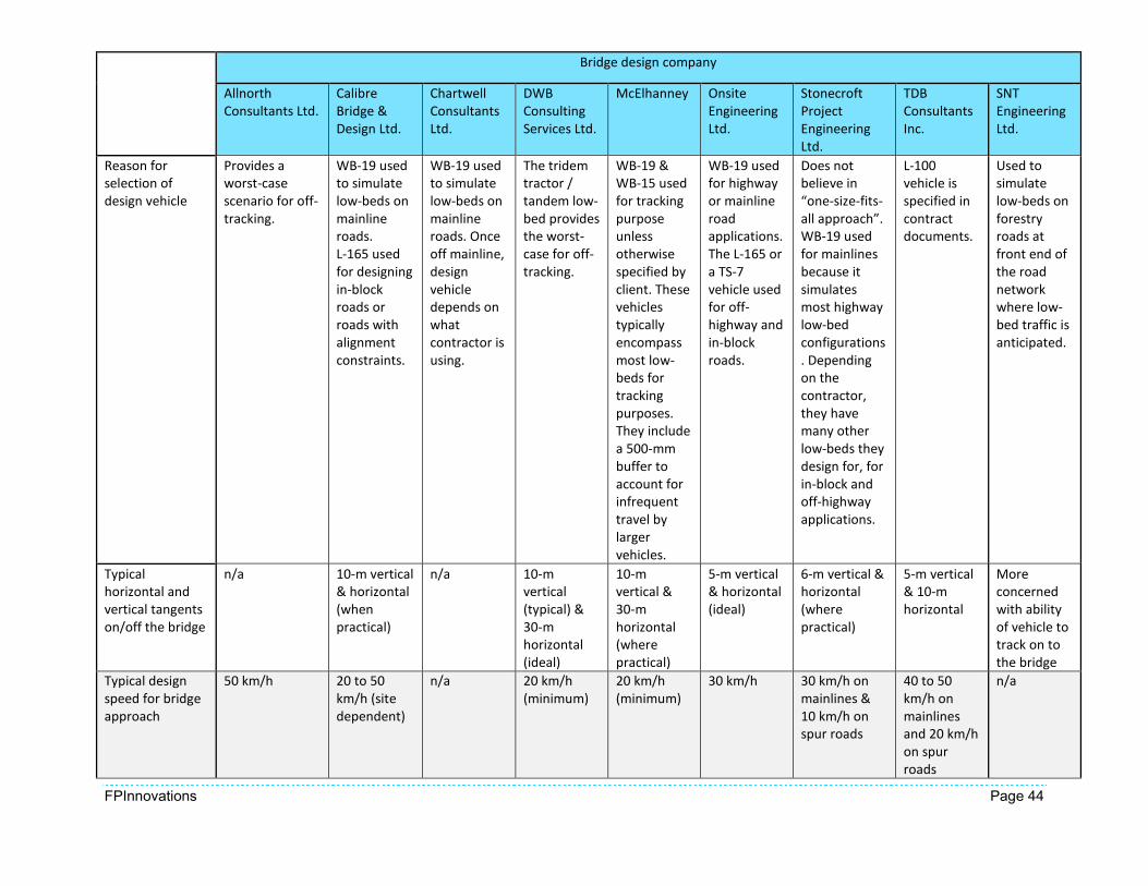
FPInnovations Page 44
Bridge design company
Allnorth
Consultants Ltd.
Calibre
Bridge &
Design Ltd.
Chartwell
Consultants
Ltd.
DWB
Consulting
Services Ltd.
McElhanney Onsite
Engineering
Ltd.
Stonecroft
Project
Engineering
Ltd.
TDB
Consultants
Inc.
SNT
Engineering
Ltd.
Reason for
selection of
design vehicle
Provides a
worst-case
scenario for off-
tracking.
WB-19 used
to simulate
low-beds on
mainline
roads.
L-165 used
for designing
in-block
roads or
roads with
alignment
constraints.
WB-19 used
to simulate
low-beds on
mainline
roads. Once
off mainline,
design
vehicle
depends on
what
contractor is
using.
The tridem
tractor /
tandem low-
bed provides
the worst-
case for off-
tracking.
WB-19 &
WB-15 used
for tracking
purpose
unless
otherwise
specified by
client. These
vehicles
typically
encompass
most low-
beds for
tracking
purposes.
They include
a 500-mm
buffer to
account for
infrequent
travel by
larger
vehicles.
WB-19 used
for highway
or mainline
road
applications.
The L-165 or
a TS-7
vehicle used
for off-
highway and
in-block
roads.
Does not
believe in
“one-size-fits-
all approach”.
WB-19 used
for mainlines
because it
simulates
most highway
low-bed
configurations
. Depending
on the
contractor,
they have
many other
low-beds they
design for, for
in-block and
off-highway
applications.
L-100
vehicle is
specified in
contract
documents.
Used to
simulate
low-beds on
forestry
roads at
front end of
the road
network
where low-
bed traffic is
anticipated.
Typical
horizontal and
vertical tangents
on/off the bridge
n/a 10-m vertical
& horizontal
(when
practical)
n/a 10-m
vertical
(typical) &
30-m
horizontal
(ideal)
10-m
vertical &
30-m
horizontal
(where
practical)
5-m vertical
& horizontal
(ideal)
6-m vertical &
horizontal
(where
practical)
5-m vertical
& 10-m
horizontal
More
concerned
with ability
of vehicle to
track on to
the bridge
Typical design
speed for bridge
approach
50 km/h 20 to 50
km/h (site
dependent)
n/a 20 km/h
(minimum)
20 km/h
(minimum)
30 km/h 30 km/h on
mainlines &
10 km/h on
spur roads
40 to 50
km/h on
mainlines
and 20 km/h
on spur
roads
n/a

FPInnovations Page 45
Bridge design company
Allnorth
Consultants Ltd.
Calibre
Bridge &
Design Ltd.
Chartwell
Consultants
Ltd.
DWB
Consulting
Services Ltd.
McElhanney Onsite
Engineering
Ltd.
Stonecroft
Project
Engineering
Ltd.
TDB
Consultants
Inc.
SNT
Engineering
Ltd.
Additional notes Mainline
approach
speeds can be
>50 km/h.
Has found
AutoCAD to
be
conservative
when
determining
curve radii
and
approach
tangents.
Can be
changed to
fit in field
conditions.
Reduce
design
speeds as
appropriate,
based on
approach
curve and
terrain. Has
found that
skewed
crossings
sometimes
provide a
more cost-
effective
solution. Has
found that
industry
clients are
willing to
accept more
risk and do
not account
for 400-mm
guardrail
clearance.
Rule of
thumb for
horizontal
approach
curve is one
truck length.
Have found
that
contractors
sometimes
grade in a
super-
elevated
curve.
Typically the
vertical
curve is
more
limiting than
the
horizontal in
respect to
the
topography.
On the
Coast,
clearance
for bridge
rails etc. not
provided;
Southern
Interior
provides this
information.
May choose to
widen deck on
log stringer
bridges to
allow for off-
tracking.
FLNRO specs
higher than
with private
clients who
are willing to
accept more
risk.
For roads
further back
in the
system
where low-
beds are not
anticipated,
will design
based on a
logging
truck. Often
have short
wide spans
to
accommoda
te turning
on the
bridge deck.
Also
commonly
use flared
bridge
panels on
ends.

FPInnovations Page 46
11. APPENDIX B – OFF-TRACKING RESULTS
Curve path and design
vehicle
Steering track
width
(m)
Trailer
track
width
(m)
A
(m)
C
(m)
B
(m)
D
(m)
X
(m)
Effective
length –
L
(m)
Off-
tracking
(m)
Maximum
swept path /
road width
(m)
AutoTUR
N
required
road
width
(m)
15 m-radius curve through 90°
5-axle off-highway long-
load logging truck (LLT)
(L series vehicles)
2.44 2.44 5.90 0.32 6.59 1.60 5.95 10.77 3.70 6.14 6.19
L-100 2.44 2.60 5.41 -2.29 6.71 0.00 0.00 8.31 2.24 4.84 5.86
L-150 2.95 2.95 5.41 -2.29 6.71 0.00 0.00 8.31 2.24 5.19 5.96
L-165 2.95 2.95 5.41 -2.29 6.25 0.00 0.00 7.94 2.05 5.00 5.83
Tractor/semitrailer
combinations
(WB series vehicles)
WB-19 2.60 2.60 6.20 0.00 12.00 0.00 0.00 13.51 6.13 8.73 7.48
WB-20 2.60 2.60 6.20 0.00 12.40 0.00 0.00 13.86 6.60 9.20 7.70
Low-bed
Tridem tractor /
tridem trailer
2.44 3.05 6.80 0.00 12.46 0.00 0.00 14.20 7.13 10.18 8.08
35 m-radius curve through 90°
5-axle off-highway long-
load logging truck (LLT)
(L series vehicles)
2.44 2.44 5.90 0.32 6.59 1.60 5.95 10.77 1.67 4.11 4.30
L-100 2.44 2.60 5.41 -2.29 6.71 0.00 0.00 8.31 1.00 3.60 4.51
L-150 2.95 2.95 5.41 -2.29 6.71 0.00 0.00 8.31 1.00 3.95 4.51
L-165 2.95 2.95 5.41 -2.29 6.25 0.00 0.00 7.94 0.91 3.86 4.43
Tractor/semitrailer
combinations
(WB series vehicles)
WB-19 2.60 2.60 6.20 0.00 12.00 0.00 0.00 13.51 2.61 5.21 5.21
WB-20 2.60 2.60 6.20 0.00 12.40 0.00 0.00 13.86 2.75 5.35 5.36
Low-bed
Tridem tractor /
tridem trailer 2.44 3.05 6.80 0.00 12.46 0.00 0.00 14.20 2.88 5.93 5.66

FPInnovations Page 47
Curve path and design
vehicle
Steering track
width
(m)
Trailer
track
width
(m)
A
(m)
C
(m)
B
(m)
D
(m)
X
(m)
Effective
length –
L
(m)
Off-
tracking
(m)
Maximum
swept path /
road width
(m)
AutoTUR
N
required
road
width
(m)
100 m-radius curve through 90°
5-axle off-highway long-
load logging truck (LLT)
(L series vehicles)
2.44 2.44 5.90 0.32 6.59 1.60 5.95 10.77 0.58 3.02 3.17
L-100 2.44 2.60 5.41 -2.29 6.71 0.00 0.00 8.31 0.35 2.95 3.68
L-150 2.95 2.95 5.41 -2.29 6.71 0.00 0.00 8.31 0.35 3.30 3.68
L-165 2.95 2.95 5.41 -2.29 6.25 0.00 0.00 7.94 0.32 3.27 3.66
Tractor/semitrailer
combinations
(WB series vehicles)
WB-19 2.60 2.60 6.20 0.00 12.00 0.00 0.00 13.51 0.92 3.52 3.55
WB-20 2.60 2.60 6.20 0.00 12.40 0.00 0.00 13.86 0.97 3.57 3.55
Low-bed
Tridem tractor /
tridem trailer
2.44 3.05 6.80 0.00 12.46 0.00 0.00 14.20 1.01 4.06 3.78

FPInnovations Page 48
12. APPENDIX C – DISCUSSIONS WITH FLNRO ENGINEERING STAFF: SUMMARY
Topic/question
Coastal Engineering
Group
(Chilliwack)
Coastal Engineering
Group
(Vancouver Island)
Northern Engineering
Group
(Prince George)
Southern Engineering
Group
(Kamloops)
Is a design vehicle
specified?
What is the design
vehicle, and why?
• WB-19 with 300-mm to
500-mm clearance
depending on site
conditions is specified
for mainline roads, and
for access to
communities or high-
value recreation.
• BCL-625 specified for
blocks accessed by
highway configuration
trucks.
• L series truck specified
for off-highway
conditions, but
depends on the site.
• WB-19 with 500-mm
clearance specified
based on experience
and field
measurements of
various off-highway
configuration low-
beds in the north
Vancouver Island
area.
• No vehicle specified
for alignment
purpose.
• Specify the L-100 for
loading.
• WB-19 with 500-mm
clearance is specified for
mainline roads.
• Staff has measured
several low-beds that
frequent mainline roads,
and found the WB-19 is
an adequate envelope
vehicle for the roads.
• A 500-mm clearance
provides an added
buffer in the event
larger vehicles, or other
stakeholders, use the
roads and are not
familiar with crossing
alignments.
• Secondary road bridge
approach alignment
varies, and relies on
professional judgement.
Are alignment
criteria specified?
What are the criteria
and why?
• Best practice is FS
Bridge Design & Const.
Manual (Engineering
Branch 1999), 10-m
horizontal tangent and
10-m vertical tangent.
• Often this not possible
on steep roads with
tight curves.
• Often allow designers
• The 15 m specified in
the Engineering
Manual (Engineering
Branch 2013) is ideal;
however, alignment is
site dependent.
• Main concern is
confirming the WB-19
can safely navigate the
bridge.
• Recommend using 15-
m horizontal and 15-
m vertical tangents
specified in the
Engineering Manual
(Engineering Branch
2013).
• Typically rely on
professional
judgement, and do
• Minimum horizontal and
vertical tangents as per
FS Bridge Design &
Const. Manual
(Engineering Branch
1999).
• Recommended
horizontal alignment
based on WB-19 with
500-mm clearance

FPInnovations Page 49
Topic/question
Coastal Engineering
Group
(Chilliwack)
Coastal Engineering
Group
(Vancouver Island)
Northern Engineering
Group
(Prince George)
Southern Engineering
Group
(Kamloops)
to reduce tangents, and
flare or widen bridges
to accommodate off-
tracking.
• Vertical curve K values
are 12 for crest and 13
for sag curves on bridge
approaches.
not strictly hold
designers to the
tangents in the
Engineering Manual
(Engineering Branch
2013).
either side.
• Recommend providing a
LVC on bridge
approaches as long as
vehicle length, or 20-m
minimum for vertical
approach alignment.
Observations • Terrain dictates bridge
approach alignment;
often not possible to
achieve horizontal
tangents of 10 m.
• Designing bridges with
flared end panels, or
widened decks is a
common method of
mitigating tight
approach alignment.
• K-value and “hang-up”
are serious concerns.
• Tail sweep is also a
significant concern for
off-highway trucks.
• Multiple stakeholders
use the roads, and
they often have large
vehicles that bridge
approaches were not
designed to
accommodate.
• New vehicles are
becoming longer, and
wider, which pushes
the design envelope
of legacy bridges.
• There is a disconnect
between crossing design
and how the bridge
performs in the field.
• Would like to see
designers on site during
construction, and when
bridge is operational, to
get a better
understanding of how
the design affects the
users.
• Standardization would
help mitigate some of
the disconnect, and
provide an educational
opportunity for
designers to start
thinking about approach
alignment early in the
design process.

FPInnovations Page 5
Head Office
Pointe-Claire
570, Saint-Jean Blvd
Pointe-Claire, QC
Canada H9R 3J9
T 514 630-4100
Vancouver
2665 East Mall
Vancouver, BC.
Canada V6T 1Z4
T 604 224-3221
Québec
319, rue Franquet
Québec, QC
Canada G1P 4R4
T 418 659-2647
© 2015 FPInnovations. All rights reserved. Copying and redistribution prohibited.
® FPInnovations, its marks and logos are trademarks of FPInnovations