Embed Size (px)
Citation preview
PROCEDURAL STANDARDS FOR BUILDING ENCLOSURE TESTING 2013 – FIRST EDITION
NATIONAL ENVIRONMENTAL BALANCING BUREAU
ii
PROCEDURAL STANDARDS FOR BUILDING ENCLOSURE TESTING
2013 – FIRST EDITION
National Environmental Balancing Bureau 8575 Grovemont Circle Gaithersburg, Maryland 20877-4121 301-977-3698 301-977-9589 FAX www.nebb.org
iii
PROCEDURAL STANDARDS FOR BUILDING ENCLOSURE TESTING ©Copyright NEBB, 2013 FIRST EDITION – March 2013, PROCEDURAL STANDARDS FOR BUILDING ENCLOSURE TESTING NEBB DEVELOPS AND SPECIFIES STANDARDS FOR TESTING AND COMMISSIONING OF BUILDING ENCLOSURE SYSTEMS. PERFORMANCE OF THESE SERVICES ONLY BY PERSONS WHO ARE CERTIFIED OR QUALIFIED FOR ENGAGING IN THIS SPECIALTY IS ONE SUCH STANDARD. NEBB SOLICITS INQUIRY BY ANY AND ALL PERSONS SEEKING SUCH APPROVALS. FOR MORE INFORMATION, GO TO WWW.NEBB.ORG.
This book may not be reproduced in any form without written permission of the copyright owner. These Procedural Standards were developed using reliable engineering principles and research plus consultation with, and information obtained from, manufacturers, users, testing laboratories and others having specialized experience. They are subject to revision as further experience and investigation may show is necessary or desirable. Building Enclosure Testing, which complies with these Procedural Standards, will not necessarily be acceptable, if when examined and tested, is found to have other features impairing the result intended by these Procedural Standards. The National Environmental Balancing Bureau assumes no responsibility and has no liability for the application of the principles or techniques contained in these Procedural Standards. Authorities considering adoption of these Procedural Standards must review all Federal, State, local and contract regulations applicable to the specific installation.
iv
FOREWORD The purpose of the NEBB Procedural Standards for Building Enclosure Testing is to establish a uniform and systematic set of criteria for the testing and commissioning of building enclosure systems. This publication is the first edition of the BET Procedural Standards. Similar to the other NEBB disciplines, the Procedural Standards serves as the anchor for the program. There are several standards that define building enclosure testing such as ASTM E779 Air Leakage Testing and ASTM E1827 Building Airtightness. Additionally ASTM C1060 defines the standards for thermography. These publications define the testing procedures to be used when performing BET and are well recognized and respected in this area of expertise. The NEBB discipline builds on these standards and complements them by providing a program combining the testing requirements with a complete package for firm and professional certification. The NEBB Procedural Standards and the NEBB Building Enclosure Testing (BET) program define the requirements for certification of the firm, for certification of the professional, for educational and experience requirements, for reporting consistencies, and for instrumentation requirements. This Procedural Standards is similar to other NEBB Procedural Standards in that it is divided into two distinct Parts: Standards and Procedures. These standards and procedures are intended as the minimum NEBB requirements a NEBB BET Certified Firm follows when performing testing of building enclosure systems and reporting the results. Contract documents may supersede the NEBB requirements. These BET Procedural Standards have been carefully compiled and reviewed by the NEBB Technical Committees. Part 1 STANDARDS Part 1, STANDARDS, covers the requirements for Quality Control and Compliance, Responsibilities, Instrumentation Requirements and BET Reports. The report requirements allow the NEBB Certified Firm more flexibility in designing reports by prescribing sets of information required to complete a BET Report. Part 2 PROCEDURES Part 2, PROCEDURES, covers required Safety Requirements and Overview of Testing Requirements and Testing Procedures to be followed when using the ASTM or other tests. This Procedural Standards allows flexibility. APPENDICES The Appendices are normative and informative. They include a suggested NEBB BET specification, sample calculations, illustrations, references, engineering formulas, definitions and instruments. This edition of the BET Procedural Standards, when used by NEBB BET Certified Firms, assures the building owner of standard accurate reporting of building enclosure testing.
v
BUILDING ENCLOSURE TESTING COMMITTEE MEMBERS AND OTHER CONTRIBUTORS FOR CURRENT EDITION
Current BET Committee: William Neudorfer – Chairman Seattle, WA
James Bochat Phoenix, AZ
Phil Emory Seattle, WA
Stan Fleischer Baltimore, MD
Rodney Hinton Greenville, SC
Additional Contributors to the First Edition: Tom Meyer Gaithersburg, Maryland
Andrew P. Nolfo, P.E. Sun City West, Arizona
NEBB BET PROCEDURAL STANDARDS TABLE OF CONTENTS
vi
TABLE OF CONTENTS PAGE Foreword iv NEBB Building Enclosure Testing Committee v Table of Contents vi
PART 1 – STANDARDS Section 1 Definitions 1
Section 2 NEBB Program, Quality Control and Compliance 7 2.1 NEBB Programs 7
2.1.1 NEBB Disciplines 7 2.1.2 Certification of Firms 7 2.1.3 Certification of Professionals 7
2.1.4 Recertification Requirements 8 2.2 Quality Assurance Program – Conformance Certification 8 2.2.1 Program Advantages 8 2.2.2 NEBB Quality Assurance Program Certificate 8 2.3 Quality Control and Compliance 8 2.3.1 BET Work Compliance 8
2.4 BET Professional Responsibilities 9 2.4.1 Execution of BET Procedures 9 2.4.2 Technician Training 10 2.4.3 BET Procedures Training 10 2.4.4 Instrument Use and Maintenance 10 2.4.5 Coordination / Supervision 10 2.4.6 Project Communication 10 2.4.7 Work Completion 10 2.4.8 Compilation and Submission of Final BET Reports 11
Section 3 Responsibilities 13
3.1 Introduction 13 3.2 Design and Construction Team Responsibilities 13
3.2.1 Design Professional’s Responsibilities 13 3.2.2 Construction Team Responsibilities 14 3.2.3 NEBB BET Certified Firm Responsibilities 15
Section 4 Standards for Instrumentation and Calibration 17 4.1 Minimum Instrumentation 17 4.2 Range and Accuracy 17 4.3 Calibration 17
NEBB BET PROCEDURAL STANDARDS TABLE OF CONTENTS
vii
PAGE Section 5 Standards for Reports and Forms 21
5.1 Reports 21 5.2 Required Forms 21 5.2.1 Report Title 21 5.2.2 Report Certification 22 5.2.3 Table of Contents 22 5.2.4 Report Summary / Remarks 22 5.2.5 All Report Pages 23 5.2.6 Instrument Calibration 23
5.2.7 Abbreviations 23 5.2.8 Building Enclosure Testing 23 5.2.9 Thermography Testing 24
PART 2 - PROCEDURES Section 6 Project Health and Safety 27 6.1 Introduction 27 6.2 Designing a Health and Safety Program 27 6.2.1 Designing a Program Policy 27 6.2.2 Designing a Training Program 28 6.2.3 Essentials of the Health and Safety Program 28 6.3 Responsibilities 28 6.3.1 Individual Health and Safety Responsibilities 28 6.3.2 NEBB Certified Professional/Safety Officer Responsibilities 29 6.3.3 Field Technician Responsibilities 29 6.4 Elements of the Program 29 6.4.1 Project Specific Items 30 6.4.2 Health and Safety Implementation 30 6.5 Safety Issues Relating to Building Enclosure Testing 30 6.5.1 Eye Protection 30 6.5.2 Equipment Guards 31 6.5.3 Noise Protection 31 6.5.4 Debris and Fumes 31 6.5.5 Temperature 31 6.5.6 Combustion Fumes 31 6.5.7 Safety Clothing 31
Section 7 Overview of Testing Requirements 33 7.1 Introduction 33 7.2 Test Setup Procedures 33 7.2.1 Building Enclosure Air Leakage Tests 33 7.2.2 Building Enclosure Thermography Tests 35 7.3 Preliminary Test Procedures 35 7.3.1 Air Leakage Tests 35 7.3.2 Thermography Tests 36
NEBB BET PROCEDURAL STANDARDS TABLE OF CONTENTS
viii
PAGE
Section 8 Building Enclosure Test Procedures 39 8.1 Introduction 39 8.2 Airflow Leakage Testing Methods 39
8.2.1 Instruments and Equipment 39 8.2.2 Common Test Procedures 40 8.2.3 Blower Door Test Method Procedures 42 8.2.4 Building Air Moving Equipment System Test Method Procedures 43 8.2.5 Data Analysis and Calculations 45 8.2.6 Acceptance 46 8.2.7 Reporting 46 8.3 Building Enclosure Thermography & Leak Testing Procedures 46
8.3.1 Instruments and Equipment 47 8.3.2 Test Procedures 47 8.3.3 Data Analysis and Interpretation 47 8.3.4 Acceptance 48 8.3.5 Reporting 48
APPENDICES Informative Appendix A Sample BET Specification 36 Informative Appendix B References and Referenced Publications 51 Informative Appendix C Engineering Formula and Examples 54 Normative Appendix D Definitions and Acronyms 91 Normative Appendix E Instrument Table 98
NEBB BET PROCEDURAL STANDARDS SECTION 1 DEFINITIONS
1
PART 1 - STANDARDS
Section 1: DEFINITIONS Definitions and acronyms are standardized throughout NEBB disciplines. Definitions and acronyms appropriate for this discipline are included as Normative Appendix D, Definitions and Acronyms. The normative appendices to NEBB Procedural Standards are considered to be integral parts of the mandatory requirements of the Procedural Standards, which, for reasons of convenience, are placed apart from all other normative elements.
NEBB BET PROCEDURAL STANDARDS SECTION 2 NEBB PROGRAM, QUALITY CONTROL
AND COMPLIANCE
2
Section 2: NEBB PROGRAM, QUALITY CONTROL AND COMPLIANCE
2.1 NEBB PROGRAMS The National Environmental Balancing Bureau (NEBB) is a not-for-profit organization founded in 1971 to:
a) develop standards, procedures and programs for the performance of testing, balancing and commissioning of building systems,
b) promote advancement of the industry through technical training and development, c) operate programs to certify firms and certify professionals who meet and maintain NEBB
Procedural Standards with integrity.
Additional information on NEBB Programs is available at www.nebb.org. 2.1.1 NEBB DISCIPLINES NEBB establishes and maintains standards, procedures, and specifications for work in its various disciplines, which include:
a) Testing-Adjusting-Balancing (TAB) -- Air and Hydronic Systems b) Sound Measurement c) Vibration Measurement d) Cleanroom Performance Testing (CPT) e) Building Systems Commissioning (BSC) f) Fume Hood Performance Testing (FHT) g) Retro-Commissioning (RCx) h) Building Enclosure Testing (BET)
Each discipline is anchored by a NEBB Procedural Standards that provides guidance for work to be performed. NEBB also has created technical manuals, training materials and programs, and seminars to enhance and support each discipline. 2.1.2 CERTIFICATION OF FIRMS NEBB certifies firms meeting certain criteria, ensuring strict conformance to its high standards and procedures. Among other requirements, NEBB BET Certified Firms must document a record of responsible performance, own a complete set of instruments and equipment required for the sophisticated techniques and procedures necessary to take and report building enclosure testing performance and have a NEBB BET Certified Professional as a full-time employee. 2.1.3 CERTIFICATION OF PROFESSIONALS NEBB establishes professional qualifications for the supervision and performance of work in its various disciplines. NEBB BET Certified Professionals must have extensive experience, and they must pass appropriate, college-level written examinations and demonstrate certain practical working knowledge and proficiency in the use of instruments required for the various disciplines. 2.1.4 RECERTIFICATION REQUIREMENTS
NEBB BET PROCEDURAL STANDARDS SECTION 2 NEBB PROGRAM, QUALITY CONTROL
AND COMPLIANCE
3
Through the recertification procedures, the firm must verify its NEBB BET Certified Professional is still on staff and it continues to own a complete set of instruments in current calibration. In addition, the firm's NEBB BET Certified Professional renews his or her certification. Among other requirements, the Certified Professional must keep abreast of developments in their discipline by successfully completing continuing education requirements annually. 2.2 QUALITY ASSURANCE PROGRAM (QAP) NEBB credibility is built by maintaining integrity through high standards, quality programs, and demonstrated capabilities of its certified firms. The QAP provides NEBB customers with a single contact for prompt professional support in understanding issues impeding successful project completion and help in mediating differences between the NEBB customer and the NEBB professional. The NEBB Quality Assurance Program is described in detail in a separate publication, available at www.nebb.org.
2.3 QUALITY CONTROL AND COMPLIANCE Building owners are entitled to professional service by every NEBB Certified Firm on every project, whether the job is NEBB-specified or not. It is the responsibility of the NEBB BET Certified Firm and its NEBB BET Certified Professional to establish and maintain procedures and practices that assure a consistent pattern of high quality work on all projects. This point cannot be overemphasized. 2.3.1 BET WORK COMPLIANCE The design professional or the owner / buyer adequately define the scope of the building enclosure testing services. Many of today’s contract documents do not define the actual scope of services to be performed on the project. Contract documents may reference desired procedures and may include statements such as "…the work will be performed in accordance to NEBB Standards…" or, the contract documents may refer to NEBB and that building enclosure testing work “…is done in accordance with the reference standard…” or, merely allude to the NEBB organization, ASHRAE, or ASTM, or owner / buyer defined reference standards and make reference to building enclosure testing work.
When contract documents do not clearly identify the exact scope of building enclosure testing services, the NEBB BET Certified Professional makes every attempt to have the design professional, or the owner / buyer, dictate the actual scope of work. Regardless of the scope of work, in all cases the process by which the data is acquired conforms to the current edition of the NEBB Procedural Standards for Building Enclosure Testing. References to desired procedures may include statements such as "the work will be performed in accordance to NEBB standards." When specifications indicate the building enclosure testing work is to be performed in accordance with NEBB Procedural Standards, the BET procedures will conform to the current edition of the NEBB Procedural Standards for Building Enclosure Testing and performed by a NEBB certified firm. The scope of work is performed as specified in the contract documents or as agreed to between the owner / buyer and the NEBB BET Certified Firm. Each relevant or applicable item as identified in the scope of work shall be performed and recorded in NEBB BET Final Report. Data presented in the NEBB BET Final Report shall provide an accurate record of the system tests, measurements, data and information.
NEBB BET PROCEDURAL STANDARDS SECTION 2 NEBB PROGRAM, QUALITY CONTROL
AND COMPLIANCE
4
a. The NEBB BET Certified Firm and the NEBB BET Certified Professional are allowed to sign and stamp a building enclosure testing report as a NEBB BET Certified Report only when the procedures and requirements as identified in these Procedural Standards have been followed.
b. A NEBB BET Certified Report might consist of any single primary test or any combination of
tests as described in these Procedural Standards. To qualify as a NEBB Certified Report, the procedures and requirements for each primary test included in the report adheres to the requirements of these Procedural Standards.
c. For some projects, the scope of work for building enclosure testing requires testing
requirements, procedures, reporting requirements, etc. different from those required by this Procedural Standards. The scope of work may require testing to another industry standard or an owner / buyer defined set of testing requirements. For these projects, the BET Certified Final Report is signed and stamped as a NEBB BET Certified Report only if the procedural variances are clearly delineated in the project scope of work and identified on the Report Certification Page. See Section 5.2.2.
d. Any project that does not comply with the minimum requirements of this Procedural Standards
and does not clearly identify the specific procedural variances required by the contract on the certification page will not be signed and stamped as a NEBB BET Certified report. All references to NEBB, including NEBB logos, stamps, certifications, etc. will be removed from the report.
2.4 BET PROFESSIONAL RESPONSIBILITIES It is the responsibility of the NEBB BET Certified Professional to control the quality of the building enclosure testing work. This means the NEBB BET Certified Firm, through its NEBB BET Certified Professional, satisfies the contract obligations set forth in the drawings and applicable specifications. 2.4.1 EXECUTION OF BUILDING ENCLOSURE TESTING PROCEDURES The NEBB BET Certified Professional has project responsibility, which includes authority to represent the NEBB BET Certified Firm. Examples of project responsibility include labor decisions, negotiating change orders, committing to contract interpretations and implementing changes in job schedules. The NEBB BET Certified Professional has the responsibility to assure the measurements of the building enclosure testing have been performed in accordance with these Procedural Standards and the contract documents to assure the accuracy of all data included in the final report. Factors such as instrument use, coordination / supervision, work instructions, and project communication play a critical role in achieving this requirement. 2.4.2 TECHNICIAN TRAINING The NEBB BET Certified Professional has a responsibility to assure technicians performing the work are properly trained and possess sufficient skills. Subjects emphasized are building enclosure testing procedures, instrument use and maintenance, safety procedures, coordination and supervision, and project communication. 2.4.3 BET PROCEDURES TRAINING NEBB BET Certified Professionals must be prepared to completely measure and record data in the manner specified. It is mandatory NEBB BET Certified Professionals possess the ability to perform the specific tasks and procedures required for each project. An understanding of building system
NEBB BET PROCEDURAL STANDARDS SECTION 2 NEBB PROGRAM, QUALITY CONTROL
AND COMPLIANCE
5
fundamentals and operating characteristics is important, and technicians must possess rudimentary knowledge of all related systems and procedural considerations. This requires periodic training to promote knowledge and skill development as well as to facilitate the transfer of knowledge and basic skills in the use of new technology. 2.4.4 INSTRUMENT USE AND MAINTENANCE NEBB BET Certified Professionals possess knowledge and skill in the proper use and care of instruments required to perform the work. This includes a thorough understanding of the operating principles and use of building enclosure testing instrumentation. Considerations for the delicate nature of many of the instruments typically used, as well as the adverse effects of dirt, shock, jarring movements and exceeding rated capacities, are addressed along with the proper methods for storing and transporting the instruments. 2.4.5 COORDINATION / SUPERVISION The NEBB BET Certified Professional is responsible for directing technicians in performing the work. Instructions delineate items such as the scope of work, location, type and quantity of measurements, etc. so field personnel know what to do and what is required of them. 2.4.6 PROJECT COMMUNICATION The NEBB BET Certified Professional reports on progress made toward work completion, when required, as well as report and address problems if encountered. When a problem exists, the NEBB BET Certified Professional notifies appropriate project personnel. 2.4.7 WORK COMPLETION The NEBB BET Certified Professional determines when the building enclosure testing work has been completed, and when to submit the report. Generally, the specified building enclosure testing field work is complete when: a) All specified building enclosure testing is completed;
or
b) Reasonable efforts within the extent of testing the building enclosure have been performed in an effort to complete all required measurements. The NEBB BET Certified Professional notifies the appropriate project personnel of any significant deficiencies preventing building enclosure testing from being performed before the final report is submitted.
2.4.8 COMPILATION AND SUBMISSION OF FINAL BET REPORTS Reports include information and data to provide an accurate quantitative and qualitative record of system measurements and information. Reports also include notes and comments, as appropriate, to provide the reviewer with additional details related to the test procedure and results. Reports meet the criteria listed in Section 5. The certification page bears the stamp of the NEBB BET Certified Professional. The stamp on the certification page is signed as evidence the NEBB BET Certified Professional has personally reviewed and accepted the report.
NEBB BET PROCEDURAL STANDARDS SECTION 3 RESPONSIBILITIES
6
Section 3: RESPONSIBILITIES
3.1 INTRODUCTION Many approaches can be taken to deliver successful performance testing of building enclosures on a project. In order to maximize value and benefits from building enclosure testing, it is important to understand the design professionals and other construction team members have responsibilities affecting the outcome of the building enclosure testing. The following outline represents recommended practices that take place on a conventional design/bid/buy/construct delivery project or on a direct procurement project between the Owner/Buyer and the NEBB BET Certified Firm. While other delivery approaches exist, the overall concept of the delineation of responsibilities remains. The Owner/Buyer must be the responsible party who dictates the recommended following procedures.
3.2 DESIGN AND CONSTRUCTION TEAM RESPONSIBILITIES 3.2.1 DESIGN PROFESSIONAL’S RESPONSIBILITIES The contract documents:
a) Specify the building enclosure systems and scope of testing services to be performed for the project. NEBB Procedural Standards and procedures define industry best practices to perform the measurements.
b) Define who retains the services of the NEBB BET Certified Firm and require the NEBB BET
Certified Firm be retained early in the construction process.
c) Clearly define in the contract documents all building enclosure testing requirements including delineation of which Standard is to be used to perform the air barrier test (i.e. NEBB – BET, ASTM 779, ASTM 1827, ASTM 1186, etc.).
d) Clearly define in the contract documents if the test will be performed utilizing the Blower Door Test Method or the Building Air Moving Equipment System Test Method.
e) Clearly define in the contract documents the acceptable leakage rate at a defined test pressure.
f) Clearly define in the contract documents the data analysis to be used.
g) Clearly define in the contract documents the precision to be used in the data analysis.
h) Clearly define in the contract documents the error to be used in the data analysis.
i) Clearly define in the contract documents the reporting requirements.
NEBB BET PROCEDURAL STANDARDS SECTION 3 RESPONSIBILITIES
7
j) Clearly identify in the contract documents the building enclosure boundary and clearly indicate the location of the air barrier throughout the building floors, walls and ceiling (roof), and the air barrier enclosure area (in m² or ft²) . If multiple zones are to be tested then the zones are shown.
k) For building pressure tests utilizing the Building Air Moving Equipment Systems Test Method,
specify all of the building’s mechanical, electrical, and other systems are completely operational, under control and performing according to the design intent prior to performing building enclosure testing. This includes all building automation / controls are installed, operational, calibrated and functioning properly. Building enclosure testing performed prior to completion of these activities is avoided.
l) Provide adequate access to all equipment and components required by the building enclosure
testing process.
3.2.2 CONSTRUCTION TEAM RESPONSIBILITIES Members of the construction team:
a) Provide the NEBB BET Certified Firm with a conformed set of contract documents pertaining to the air barrier (drawings, specifications, and approved submittals), including all current approved change orders and contract modifications.
b) Develop project schedule, with the input of the NEBB BET Certified Firm that coordinates the
work of other disciplines and provides adequate time in the construction process to allow successful completion of the building enclosure testing and remedial work.
c) Notify the NEBB BET Certified Firm of all schedule changes. d) Ensure the building enclosure is complete, including but not limited to, all structural components,
the air barrier and vapor barrier complete, windows and doors installed, door hardware complete, door sweeps and weather stripping complete, floor and ceilings complete. Ensure the building enclosure and components are complete and operational such that the performance of the building enclosure tests would not be adversely affected.
e) Prepare the building enclosure for test as described in Table 8-1.
f) Building preparation is NOT the responsibility of the NEBB BET Certified Firm.
g) Provide temporary or permanent power for BET tests.
h) For building pressure test method using the Building Air Moving Equipment systems:
1) Ensure all necessary building systems are complete and are operating in a safe manner. 2) Complete the installation of permanent electrical power systems serving the building
systems. Such electrical systems are properly installed in accordance with all applicable codes to ensure the safety of all construction personnel.
3) Perform startup of all building systems in accordance with manufacturers' recommendations.
4) Complete the installation, programming, calibration and startup of all building control systems.
NEBB BET PROCEDURAL STANDARDS SECTION 3 RESPONSIBILITIES
8
3.2.3 NEBB BET CERTIFIED FIRM RESPONSIBILITIES The NEBB BET Certified Firm:
a) Follows current NEBB standards and procedures when performing the building enclosure testing.
b) Communicates on a regular basis, through proper channels, items pertaining to design,
installation or function preventing the NEBB BET Certified Firm from achieving completion of the BET work in accordance with the current edition of the NEBB Procedural Standards for Building Enclosure Testing.
c) Performs the required building enclosure tests. If the leak test does not pass, and if required by
code or contract, then performs leak identification inspections using smoke, thermography or other approved testing methods. Perform leak identification inspections in conjunction with building pressure tests.
d) Publishes a NEBB BET Certified Report of final conditions accurately reflecting the results of the building enclosure testing.
NEBB BET PROCEDURAL STANDARDS SECTION 4 STANDARDS FOR EQUIPMENT, INSTRUMENTATIONS
AND CALIBRATION
9
Section 4: STANDARDS FOR EQUIPMENT, INSTRUMENTATION AND CALIBRATION
4.1 MINIMUM INSTRUMENTATION
A NEBB BET Certified Firm uses a variety of instrumentation to perform the specified building enclosure tests on a project. It is the responsibility of the NEBB BET Certified Firm to provide appropriate instrumentation meeting the minimum requirements for use on a project. Instrumentation used on a NEBB project is in proper operating condition and is applied in accordance with the manufacturer’s recommendations. Normative Appendix E lists the minimum instrumentation specifications a NEBB BET Certified firm uses in all building enclosure testing. The NEBB BET Certified Firm owns all of the required instrumentation and equipment as identified in Normative Appendix E.
4.2 RANGE AND ACCURACY The accuracy and range as reported by the instrument manufacturer is verified by a testing laboratory traceable to the National Institute of Standards and Technology (NIST) or equivalent institute in countries other than the United States. Calibration requirements for each function are specified and met. Some instruments and accessories do not require calibration. However, if a "mechanical / electrical" device is substituted or employed in place of these types of instruments, the indicated calibration requirements noted apply. Instrumentation with multiple capabilities are accepted for more than one function when submitting documentation for a firm’s certification, providing each separate function meets NEBB requirements.
4.3 CALIBRATION All building enclosure testing instrumentation meets manufacturer’s calibration requirements.
Firms with multiple sets of instrumentation calibrate all instrumentation used by the firm on BET projects in accordance with Normative Appendix E as a minimum requirement for NEBB certification.
NEBB BET PROCEDURAL STANDARDS SECTION 5 STANDARDS FOR REPORTS AND FORMS
10
Section 5: STANDARDS FOR REPORTS AND FORMS 5.1 REPORTS The NEBB Procedural Standards for Building Enclosure Testing establishes minimum requirements of a NEBB BET Certified Report. NEBB does not require the use of NEBB produced forms. Customized forms are acceptable based on the data acquisition requirements of this section. Where contract document data reporting requirements exceed the minimum requirements of NEBB, the NEBB BET Certified Firm is responsible to meet the requirements of the contract documents. NEBB Building Enclosure Testing Reports include:
A. Report Title
B. Report Certification
C. Table of Contents
D. Report Summary / Remarks
E. Appropriate Forms
F. Instrument Calibration
G. Abbreviations
5.2 REQUIRED FORMS Listed below are the requirements for each NEBB BET Certified Report. 5.2.1 REPORT TITLE Required Data: The heading: “Certified Building Enclosure Testing Report”; Project Name, Address, NEBB BET Certified Firm Name, Address, Contact Information and Certification Number. Optional Data: Architect Name, Address and Contact Information; General Contractors Name, Address and Contact Information.
5.2.2 REPORT CERTIFICATION The certification page bears the stamp of the NEBB BET Certified Professional. The stamp on the certification page is signed as evidence the NEBB Professional has reviewed and accepted the report.
NEBB BET PROCEDURAL STANDARDS SECTION 5 STANDARDS FOR REPORTS AND FORMS
11
Data: Project Name; Certifying NEBB BET Certified Professional’s Name; Firm Name; Certification Number; Expiration Date; Certifying NEBB BET Certified Professional’s NEBB Stamp (signed & dated); and the following exact certification verbiage. Where building enclosure testing was performed in complete accordance with the requirements of this Procedural Standards, the following exact verbiage is used on the Report Certification page: "THE DATA PRESENTED IN THIS REPORT IS A RECORD OF THE BUILDING ENCLOSURE TESTING OBTAINED IN ACCORDANCE WITH THE REQUIREMENTS OF THE CURRENT EDITION OF THE NEBB PROCEDURAL STANDARDS FOR BUILDING ENCLOSURE TESTING. ANY VARIANCES FROM DESIGN / OR INDUSTRY STANDARDS WHICH EXCEED THE LIMITS SET BY THE CONTRACT DOCUMENTS, OR WHICH EXCEED THE LIMITS AGREED TO BETWEEN THE OWNER AND THE NEBB BET CERTIFIED FIRM ARE NOTED THROUGHOUT THIS REPORT AND IN THE REPORT PROJECT SUMMARY." NEBB recommends building enclosure testing be performed in accordance with the requirements of these Procedural Standards and all of the tests are performed. There are cases where the scope of work requires testing to other industry standards, or requires testing to a scope of work specified or agreed to between the owner / buyer and the NEBB BET Certified Firm owner. Under these conditions, a NEBB BET Certified Firm issues a NEBB BET Certified Report, but the procedural variances are clearly delineated in the project scope of work and the above Certification Statement is modified to reflect the actual scope of work or other industry testing standards to qualify as a NEBB Certified Report. See Section 2.3.1. Data: Disclaimer statement with the following: “The results shown and information given in this report are certified to be accurate and complete to the extent possible by equipment and procedures used on this date. ___ (Insert Company Name) _____________________________________ warrants the air barrier system identified in this report is operating at the specified levels as shown, at and only at this time, and makes no other warranties, stated or implied, concerning the continued performance of the building enclosure / test zone, past this time.” Note: The Certification Statement and the Disclaimer Statement are included on the report title page or on a separate certification page.
5.2.3 TABLE OF CONTENTS The table of contents serves as a guide to the organization of the BET report. Required Data: Page numbers of system and component information in the report.
5.2.4 REPORT SUMMARY/REMARKS A NEBB BET Certified Report includes a narrative description of test methods and system set-up conditions established prior to testing. The narrative identifies which Standard was used for testing (NEBB-BET, ASTM 779, etc.). The narrative explains the rationale for system parameters, such as the number of readings at what specified test pressures, measured airflow rates, outside temperature, the inside temperature, the wind velocity, the acceptable leakage rate, the effective leakage area, building baseline differential pressure, infrared thermal images, and the steps taken to achieve the desired test set-up.
NEBB BET PROCEDURAL STANDARDS SECTION 5 STANDARDS FOR REPORTS AND FORMS
12
This section also includes a listing of deficiencies in the summary and identifies the appropriate pages in the report. Required Data: A summary of all items exceeding Contract Document tolerances or any other items requiring discussion or explanation.
5.2.5 ALL REPORT PAGES All tested sections of the building enclosure included in the NEBB BET Report are clearly identified with a unique designation number or other unique descriptor.
The location of each test is identified in the report. The location identifier includes the elevation facing, the space number, or some other unique descriptor to clearly identify the item tested.
The method of identification uses schematic diagrams, architectural or mechanical plans where permissible, or a narrative description. Each data form supplied in a NEBB BET Report includes the name of the responsible technician / NEBB BET Certified Professional who reported the information, and the date and time the data was collected.
Required Data: Project name. All pages are numbered consecutively. Optional Data: Remarks section to record any information pertinent to the data reported on the data sheet. 5.2.6 INSTRUMENT CALIBRATION This is an overall listing of the instruments used to verify reported data. Required Data:
1. Instrument type 2. Instrument manufacturer 3. Instrument model number 4. Instrument serial number 5. Date of instrument calibration
5.2.7 ABBREVIATIONS This is a list of definitions of the relevant abbreviations used in the report.
Required Data: A listing of all abbreviations and definitions as used in the report. 5.2.8 BUILDING AIRFLOW LEAKAGE TEST REPORT DATA Building airflow leakage tests are presented in graphical or tabular format for each measurement plane and location and the data are reported on the test reporting form(s). Required Data: Building description including location, address (street, city, state or province, zip or postal code, country, building orientation (N, E, S, W etc.) and elevation above mean sea level in ft. (m).
1) Construction data including: a. Date built (estimate if unknown) b. Floor areas for conditioned space, attic, basement, and crawl space c. Wall areas
NEBB BET PROCEDURAL STANDARDS SECTION 5 STANDARDS FOR REPORTS AND FORMS
13
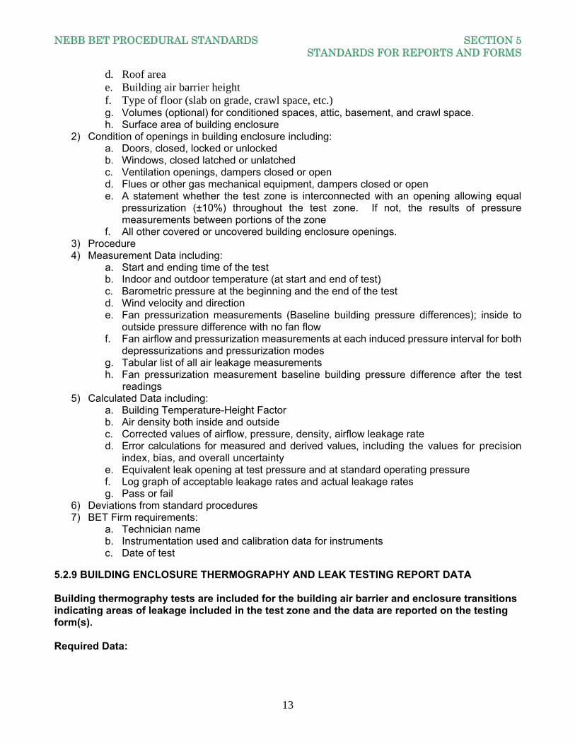
d. Roof area e. Building air barrier height f. Type of floor (slab on grade, crawl space, etc.) g. Volumes (optional) for conditioned spaces, attic, basement, and crawl space. h. Surface area of building enclosure
2) Condition of openings in building enclosure including: a. Doors, closed, locked or unlocked b. Windows, closed latched or unlatched c. Ventilation openings, dampers closed or open d. Flues or other gas mechanical equipment, dampers closed or open e. A statement whether the test zone is interconnected with an opening allowing equal
pressurization (±10%) throughout the test zone. If not, the results of pressure measurements between portions of the zone
f. All other covered or uncovered building enclosure openings. 3) Procedure 4) Measurement Data including:
a. Start and ending time of the test b. Indoor and outdoor temperature (at start and end of test) c. Barometric pressure at the beginning and the end of the test d. Wind velocity and direction e. Fan pressurization measurements (Baseline building pressure differences); inside to
outside pressure difference with no fan flow f. Fan airflow and pressurization measurements at each induced pressure interval for both
depressurizations and pressurization modes g. Tabular list of all air leakage measurements h. Fan pressurization measurement baseline building pressure difference after the test readings
5) Calculated Data including: a. Building Temperature-Height Factor b. Air density both inside and outside c. Corrected values of airflow, pressure, density, airflow leakage rate d. Error calculations for measured and derived values, including the values for precision
index, bias, and overall uncertainty e. Equivalent leak opening at test pressure and at standard operating pressure f. Log graph of acceptable leakage rates and actual leakage rates g. Pass or fail
6) Deviations from standard procedures 7) BET Firm requirements:
a. Technician name b. Instrumentation used and calibration data for instruments c. Date of test
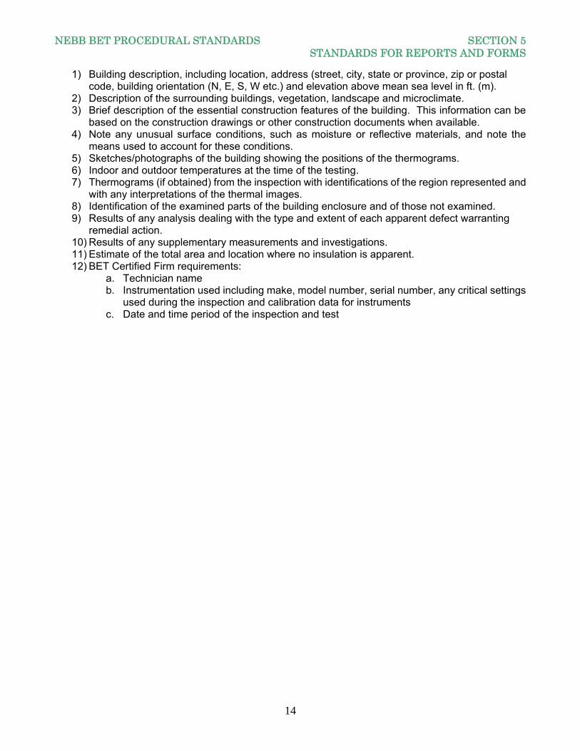
5.2.9 BUILDING ENCLOSURE THERMOGRAPHY AND LEAK TESTING REPORT DATA Building thermography tests are included for the building air barrier and enclosure transitions indicating areas of leakage included in the test zone and the data are reported on the testing form(s). Required Data:
NEBB BET PROCEDURAL STANDARDS SECTION 5 STANDARDS FOR REPORTS AND FORMS
14
1) Building description, including location, address (street, city, state or province, zip or postal code, building orientation (N, E, S, W etc.) and elevation above mean sea level in ft. (m).
2) Description of the surrounding buildings, vegetation, landscape and microclimate. 3) Brief description of the essential construction features of the building. This information can be
based on the construction drawings or other construction documents when available. 4) Note any unusual surface conditions, such as moisture or reflective materials, and note the
means used to account for these conditions. 5) Sketches/photographs of the building showing the positions of the thermograms. 6) Indoor and outdoor temperatures at the time of the testing. 7) Thermograms (if obtained) from the inspection with identifications of the region represented and
with any interpretations of the thermal images. 8) Identification of the examined parts of the building enclosure and of those not examined. 9) Results of any analysis dealing with the type and extent of each apparent defect warranting
remedial action. 10) Results of any supplementary measurements and investigations. 11) Estimate of the total area and location where no insulation is apparent. 12) BET Certified Firm requirements:
a. Technician name b. Instrumentation used including make, model number, serial number, any critical settings
used during the inspection and calibration data for instruments c. Date and time period of the inspection and test
NEBB BET PROCEDURAL STANDARDS SECTION 6 PROJECT HEALTH AND SAFETY
15
PART 2 - PROCEDURES Section 6: PROJECT HEALTH AND SAFETY 6.1 INTRODUCTION A health and safety program is a definite plan of action designed to prevent accidents and occupational diseases. A health and safety program includes the elements required by all current health and safety legislation as a minimum. This document summarizes the general elements of a health and safety program. This helps NEBB Certified firms to develop programs to deal with their specific needs. Because many small and medium-sized enterprises lack the resources of larger organizations, it is vital small and medium-sized enterprises involve all employees in health and safety activities. The more comprehensive the program is, the more employee involvement can be expected. The health and safety program discussed in this section is a guideline. The project specific safety program is as specified in the contract documents or as agreed to between the Owner/Buyer and the NEBB BET Certified Firm. The NEBB BET Certified Firm follows the client project specific safety program. In the absence of this project specific safety program, the firm’s Standard Operating Procedures (SOP) for health and safety program are followed. For this reason, the NEBB BET Certified Firm develops their own SOP for Safety for their firm. At a minimum, the NEBB BET Certified Firm’s SOP for Health and Safety includes design and implementation, responsibilities and elements of the plan as addressed below, and issues addressed in Section 6.5.
6.2 DESIGNING A HEALTH AND SAFETY PROGRAM
6.2.1 DESIGNING A PROGRAM POLICY A NEBB BET Certified Firm’s health and safety policy is a statement of principles and general rules serving as a guide for action. 6.2.1.1 The policy mentions:
a. Management's commitment to protect the safety and health of employees b. The objectives of the program c. The organization's basic health and safety philosophy d. Who is accountable for health and safety programs e. The general responsibilities of all employees f. Health and safety is not sacrificed for expediency g. Unacceptable performance of health and safety conduct is not be tolerated
6.2.1.2 The policy is:
NEBB BET PROCEDURAL STANDARDS SECTION 6 PROJECT HEALTH AND SAFETY
16
a. Stated in clear, unambiguous, and unequivocal terms b. Signed by the incumbent chief executive officer c. Kept up-to-date d. Communicated to each employee e. Adhered to in all work activities
6.2.2 DESIGNING A TRAINING PROGRAM The objective of training is to help the implementation of health and safety policies become job specific practices and accepted courses of action. It raises awareness and the skill levels of a technician to an acceptable standard. 6.2.2.1 Occasions when employee training is required:
a. Commencement of employment b. Reassignment or transfer to a new job c. Introduction of new equipment, processes, or procedures d. Inadequate performance e. Changes in customer job site related chemical or biological hazards, equipment, processes, or
procedures. 6.2.2.2 NEBB BET Certified Firm include these topics in safety training:
a. Safety and the supervisor b. Know your accident problems c. Human relations d. Maintaining interest in safety e. Instructing for safety f. Industrial hygiene g. Personal protective equipment h. Industrial housekeeping i. Material handling and storage j. Guarding machines and mechanisms k. Hand and portable power tools l. Fire protection
6.2.3 ESSENTIALS OF THE HEALTH AND SAFETY PROGRAM While different NEBB BET Certified Firms have different needs and requirements in their health and safety program consider these basic items in each case:
a. Individual responsibility b. Occupational health and / or safety representative c. Health and safety rules d. Correct work procedures e. Employee orientation f. Training g. Workplace inspections h. Reporting and investigating accidents i. Emergency procedures j. Medical and first aid k. Health and safety incentives l. Workplace specific items
NEBB BET PROCEDURAL STANDARDS SECTION 6 PROJECT HEALTH AND SAFETY
17
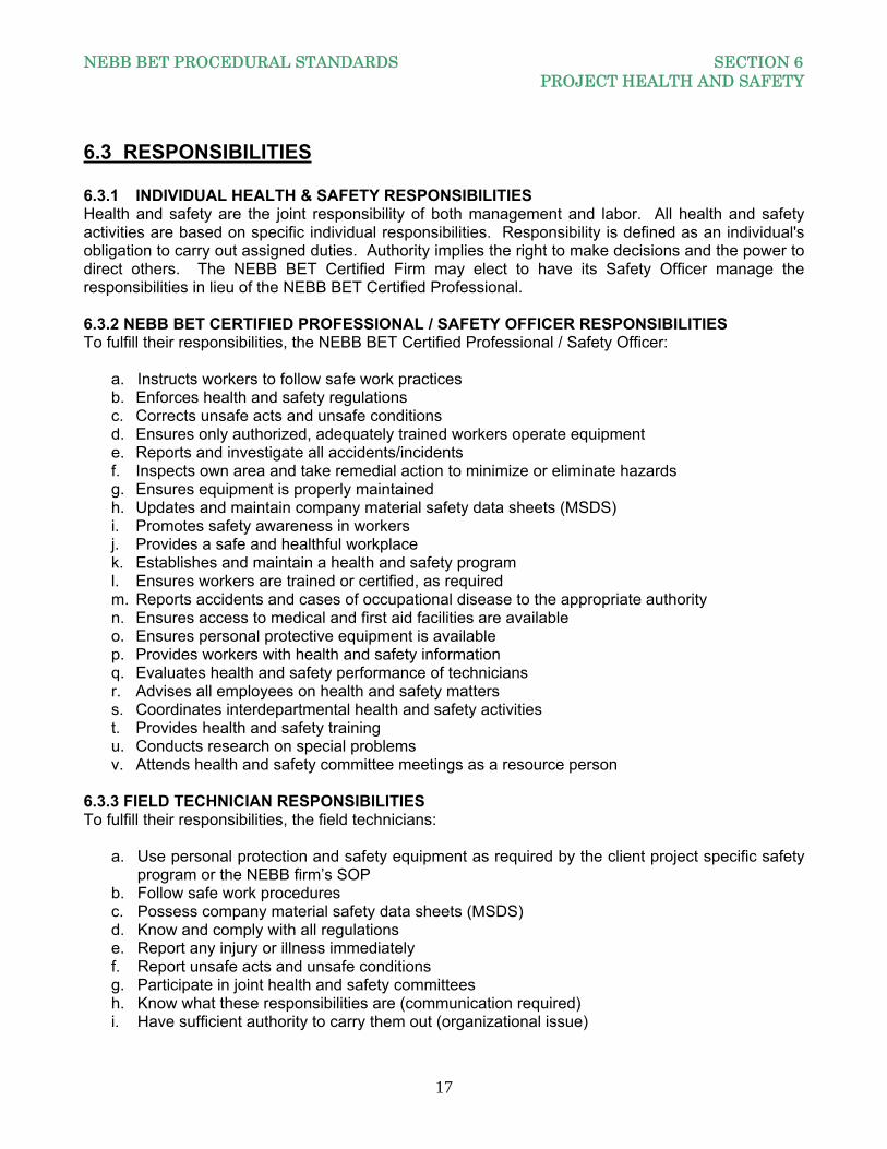
6.3 RESPONSIBILITIES 6.3.1 INDIVIDUAL HEALTH & SAFETY RESPONSIBILITIES Health and safety are the joint responsibility of both management and labor. All health and safety activities are based on specific individual responsibilities. Responsibility is defined as an individual's obligation to carry out assigned duties. Authority implies the right to make decisions and the power to direct others. The NEBB BET Certified Firm may elect to have its Safety Officer manage the responsibilities in lieu of the NEBB BET Certified Professional. 6.3.2 NEBB BET CERTIFIED PROFESSIONAL / SAFETY OFFICER RESPONSIBILITIES To fulfill their responsibilities, the NEBB BET Certified Professional / Safety Officer:
a. Instructs workers to follow safe work practices b. Enforces health and safety regulations c. Corrects unsafe acts and unsafe conditions d. Ensures only authorized, adequately trained workers operate equipment e. Reports and investigate all accidents/incidents f. Inspects own area and take remedial action to minimize or eliminate hazards g. Ensures equipment is properly maintained h. Updates and maintain company material safety data sheets (MSDS) i. Promotes safety awareness in workers j. Provides a safe and healthful workplace k. Establishes and maintain a health and safety program l. Ensures workers are trained or certified, as required m. Reports accidents and cases of occupational disease to the appropriate authority n. Ensures access to medical and first aid facilities are available o. Ensures personal protective equipment is available p. Provides workers with health and safety information q. Evaluates health and safety performance of technicians r. Advises all employees on health and safety matters s. Coordinates interdepartmental health and safety activities t. Provides health and safety training u. Conducts research on special problems v. Attends health and safety committee meetings as a resource person
6.3.3 FIELD TECHNICIAN RESPONSIBILITIES To fulfill their responsibilities, the field technicians:
a. Use personal protection and safety equipment as required by the client project specific safety program or the NEBB firm’s SOP
b. Follow safe work procedures c. Possess company material safety data sheets (MSDS) d. Know and comply with all regulations e. Report any injury or illness immediately f. Report unsafe acts and unsafe conditions g. Participate in joint health and safety committees h. Know what these responsibilities are (communication required) i. Have sufficient authority to carry them out (organizational issue)

NEBB BET PROCEDURAL STANDARDS SECTION 6 PROJECT HEALTH AND SAFETY
18
j. Have the required ability and competence (training or certification required)
6.4 ELEMENTS OF THE PROGRAM The NEBB BET Certified Professional / Safety Officer addresses the following elements of the firm’s health and safety program:
a. Establish work procedures b. Analyze project hazards c. Establish guideline rules d. Conduct employee safety orientation e. Establish emergency procedures f. Establish medical and first aid action plan g. Perform routine project site safety audits h. Complete project accident / injury reports i. Investigate project accidents/ injuries j. Establish and enforce return-to-work policy k. Promote employee involvement in health and safety programs
6.4.1 PROJECT SPECIFIC ITEMS Examples of project specific items included in health and safety programs are:
a. Material Safety Data Sheets (MSDS) b. Lock out procedures c. Chemical handling rules d. Biological material handling rules e. Personal hygiene f. Vehicle safety rules g. Working alone guidelines h. Personal protective equipment requirements
6.4.2 HEALTH AND SAFETY PROGRAM IMPLEMENTATION A good health and safety program provides a clear set of guidelines for activities, if followed, reduce accidents and cases of occupational disease. A NEBB BET Certified Professional demonstrates commitment and support of the program by:
a. Providing resources such as time, money, and personnel b. Ensuring employees receive training or certifications as required c. Making all applicable health and safety information available to all employees entitled to receive
it d. Including health and safety performance as part of employee performances appraisals at all
levels e. Attending health and safety meetings f. The program must be communicated to all employees g. Special emphasis is given to new workers and newly appointed NEBB Professionals h. Revisions to policies and procedures are publicized i. The program is available in a single written document. (However, if separate manuals have
been developed for various elements, such as accident investigation procedures, their use is referred to in the main document).
NEBB BET PROCEDURAL STANDARDS SECTION 6 PROJECT HEALTH AND SAFETY
19
6.5 SAFETY ISSUES RELATING TO BUILDING ENCLOSURE TESTING While the above sections describe the generic requirements of a Certified Firm’s SOP for health and safety, there are specific requirements incorporated in the SOP due to the nature of this testing and commissioning.
6.5.1 EYE PROTECTION Glass or other components of the building enclosure should not break at the pressures recommended for building pressure testing of 75 Pa (0.30 in.w.c. 25 MPH Wind Pressure). Take adequate precautions to protect personnel such as the use of eye protection. 6.5.2 EQUIPMENT GUARDS All air moving equipment have proper guard or cage to house the fan, blower and drives to prevent accidental access to any moving parts of the equipment. 6.5.3 NOISE PROTECTION Due to equipment generated noise levels all personnel have hearing protection available when working near rotating equipment. 6.5.4 DEBRIS AND FUMES Test fans force a large quantity of air into or out of a building while in operation. Exercise caution so excess debris or fumes from the building exterior is not introduced into the building space that could damage building contents. 6.5.5 TEMPERATURE If the ambient temperatures are very high or very low, exercise caution not to overwhelm the building interior either through the blower assembly or through the HVAC system to cause freezing or excessive heat in the building. 6.5.6 COMBUSTION FUMES Verify all combustion gases will not be affected by pressurization or depressurization of the building. It is recommended if rooms with combustion equipment cannot be pressure isolated from the test area then all combustion equipment be turned off and the fuel be manually turned off at the supply valve. After the test, verify all equipment is restarted and all pilot lights are relit. 6.5.7 SAFETY CLOTHING All personnel adhere to the project or customer requirements for safety clothing, including hard hats, safety shoes, etc.
NEBB BET PROCEDURAL STANDARDS SECTION 7 OVERVIEW OF TESTING REQUIREMENTS
20
Section 7: OVERVIEW OF TESTING REQUIREMENTS
7.1 INTRODUCTION The purpose of this section is to provide an overview of the various tests associated with building enclosure testing. The NEBB BET Certified Firm is required to perform building enclosure testing in accordance with the NEBB Procedural Standards or the various ASTM Standards. For this reason, the NEBB BET Certified Firm possesses copies of the current versions of ASTM E-779, ASTM-1827 and ASTM C-1060 in addition to the NEBB BET Procedural Standards. See Appendix B for additional references.
7.2 GENERAL OVERVIEW OF BUILDING ENCLOSURE TESTING 7.2.1 BUILDING ENCLOSURE AIR LEAKAGE TESTS Building air tightness is one factor affecting building air change rates under normal conditions of weather and building operation. Air leakage (either unwanted infiltration or exfiltration) can significantly affect the thermal performance of a building HVAC system. Additionally, occupant comfort and indoor air quality may be affected. Commercial, institutional, industrial and residential (multi-family) projects are required to provide for ventilation (outdoor) air requirements into the design of these facilities by local governing code requirements. These requirements are minimum values and can be increased by the design professional. Normal design dictates a facility’s pressurization requirements. While many buildings are designed to provide positive pressurization to minimize infiltration, significant air leakage can and does occur on a daily basis. Some of today’s codes and designs for residential dwelling units (single family) do not specifically dictate ventilation requirements and expect indoor-outdoor air exchange to occur due to air leakage from temperature differences, wind and through loose construction joints and cracks common in normal residential construction. Air also enters a building from changes in the buildings pressurization caused by bathroom and kitchen exhaust fans and the operation of combustion devices utilizing fuel-fired appliances, furnaces, and heaters. More proactive local codes and engineering designs do address ventilation issues. Quantifying the amount of air leakage and actively taking steps to minimize this leakage airflow can lead to significant energy savings, improved comfort and health safety in today’s high performance buildings. Building enclosure leakage testing is a key element in quantifying the problem. The test methods addressed in this Procedural Standards are simpler to implement than tracer gas measurements and the leakage tests are intended to characterize the air tightness of the building enclosure. The test results can be used to compare the relative air tightness of several similar buildings, to identify the leakage sources and rates of leakage from different components of the same building enclosure, and to determine the air leakage reduction from retrofit when applied to an existing building.
NEBB BET PROCEDURAL STANDARDS SECTION 7 OVERVIEW OF TESTING REQUIREMENTS
21
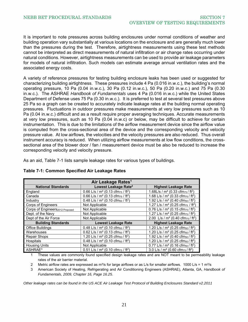
It is important to note pressures across building enclosures under normal conditions of weather and building operation vary substantially at various locations on the enclosure and are generally much lower than the pressures during the test. Therefore, airtightness measurements using these test methods cannot be interpreted as direct measurements of natural infiltration or air change rates occurring under natural conditions. However, airtightness measurements can be used to provide air leakage parameters for models of natural infiltration. Such models can estimate average annual ventilation rates and the associated energy costs. A variety of reference pressures for testing building enclosure leaks has been used or suggested for characterizing building airtightness. These pressures include 4 Pa (0.016 in.w.c.), the building’s normal operating pressure, 10 Pa (0.04 in.w.c.), 30 Pa (0.12 in.w.c.), 50 Pa (0.20 in.w.c.) and 75 Pa (0.30 in.w.c.). The ASHRAE Handbook of Fundamentals uses 4 Pa (0.016 in.w.c.) while the United States Department of Defense uses 75 Pa (0.30 in.w.c.). It is preferred to test at several test pressures above 25 Pa so a graph can be created to accurately indicate leakage rates at the building normal operating pressures. Fluctuations in outdoor pressures make measurements at very low pressures such as 10 Pa (0.04 in.w.c.) difficult and as a result require proper averaging techniques. Accurate measurements at very low pressures, such as 10 Pa (0.04 in.w.c) or below, may be difficult to achieve for certain instrumentation. This is due to the limitations of the airflow measurement device since the airflow value is computed from the cross-sectional area of the device and the corresponding velocity and velocity pressure value. At low airflows, the velocities and the velocity pressures are also reduced. Thus overall instrument accuracy is reduced. When utilizing airflow measurements at low flow conditions, the cross-sectional area of the blower door / fan / measurement device must be also be reduced to increase the corresponding velocity and velocity pressure. As an aid, Table 7-1 lists sample leakage rates for various types of buildings. Table 7-1: Common Specified Air Leakage Rates
Air Leakage Rates1 National Standards Lowest Leakage Rate2 Highest Leakage Rate
England 0.66 L/s / m² (0.13 cfm75 / ft2) 1.68L/s / m² (0.33 cfm75 / ft2) Canada 0.66 L/s / m² (0.13 cfm75 / ft2) 1.68 L/s / m² (0.33 cfm75 / ft2) Industry 0.48 L/s / m² (0.10 cfm50 / ft2) 1.92 L/s / m² (0.40 cfm50 / ft2) Corps of Engineers Not Applicable 1.27 L/s / m² (0.25 cfm75 / ft2) Corps of Engineers2012 Proposed Not Applicable 0.76 L/s / m² (0.15 cfm75 / ft2) Dept. of the Navy Not Applicable 1.27 L/s / m² (0.25 cfm75 / ft2) Dept of the Air Force Not Applicable 2.00 L/s / m² (0.40 cfm75 / ft2)
Building Standards Lowest Leakage Rate Highest Leakage Rate Office Buildings 0.48 L/s / m² (0.10 cfm50 / ft2) 1.20 L/s / m² (0.25 cfm50 / ft2) Warehouses 0.62 L/s / m² (0.13 cfm50 / ft2) 1.20 L/s / m² (0.25 cfm50 / ft2) Repair Shops 1.20 L/s / m² (0.25 cfm50 / ft2) 1.92 L/s / m² (0.40 cfm50 / ft2) Hospitals 0.48 L/s / m² (0.10 cfm50 / ft2) 1.20 L/s / m² (0.25 cfm50 / ft2) Housing Units Not Applicable 0.77 L/s / m² (0.16 cfm50 / ft2) ASHRAE3 0.51 L/s / m² (0.10 cfm75 / ft2) 3.0 L/s / m² (0.60 cfm75 / ft2)
1 These values are commonly found specified design leakage rates and are NOT meant to be permeability leakage rates of the air barrier material.
2 Metric airflow rates are expressed as m³/s for large airflows or as L/s for smaller airflows. 1000 L/s = 1 m³/s 3 American Society of Heating, Refrigerating and Air Conditioning Engineers (ASHRAE), Atlanta, GA, Handbook of
Fundamentals, 2009, Chapter 16, Page 16.25.
Other leakage rates can be found in the US ACE Air Leakage Test Protocol of Building Enclosures Standard v2.2011
NEBB BET PROCEDURAL STANDARDS SECTION 7 OVERVIEW OF TESTING REQUIREMENTS
22
Another issue in performing these tests pertains to depressurization versus pressurization. Depending on the goals of the test method, the contract documents or the Owner / Buyer choose the depressurization mode, the pressurization mode or both. This Procedural Standards requires both pressurization and depressurization for Blower Door Test Method and permits either for the Building Air Moving Equipment System Test Method. The depressurization and pressurization measurements will compensate for asymmetric flow in the two directions. Depressurization is appropriate for testing the building enclosure tightness to include the tightness of such items as back draft dampers that inhibit infiltration but open during a pressurization test. Combining the results of depressurization and pressurization measurements can minimize wind and stack-pressure effects on calculating air tightness but could overestimate air leakage due to back draft dampers that open only under pressurization. Table 8-1 in Section 8 indicates which openings are closed, covered or left open. A clear understanding of the goal of the test is required to determine which items are open or closed. Finally, the effects of wind and temperature differences must be discussed. Calm winds and moderate temperatures during the test improve precision and bias. Pressure gradients over the enclosure caused by inside-outside temperature differences and wind cause bias in the measurement by changing the building pressure differences over the test enclosure from what would occur in the absence of these factors. Wind also causes pressure fluctuations affecting measurement precision and causes the data to be auto-correlated. 7.2.2 BUILDING ENCLOSURE THERMOGRAPHY TESTS While performing infrared thermal imaging tests of a wall, roof, floor or ceiling have the potential of determining the overall thermal performance of these building components, the main emphasis of the test is two-fold 1) to determine the source and location of the infiltration or exfiltration and 2) determine if insulation is missing or if the installation of the insulation is not performing to its intended design. Anomalies in the thermal images from other apparent causes are recorded as additional information. The interpretation of these anomalies may require procedures and techniques not presented in this Procedural Standards.
7.3 PRELIMINARY TEST PROCEDURES
7.3.1 AIR LEAKAGE TESTS 7.3.1.1 Introduction Whether the NEBB BET Certified Firm is performing leakage testing in accordance with the NEBB BET Procedural Standards for Building Enclosure Testing, ASTM E779 Standard Test Method for Determining Air Leakage Rate by Fan Pressurization, ASTM E1827 Standard Test Methods for Determining Airtightness of Buildings Using an Orifice Blower Door, or another building enclosure leakage test defined by a Contract Document or Owner / Buyer defined set of criteria, the concept is the same. You are trying to quantify the amount of leakage at a given test pressure in accordance with the standard used (specified). To that end, the preliminary procedures for any of these tests are the same. 7.3.1.2 Preliminary Procedures The design professionals are responsible to define the objectives and the acceptance criteria. If they are not defined in the Contract Documents, the objectives and acceptance criteria are as agreed to between the Owner / Buyer and the NEBB BET Certified Firm. The following preliminary procedures are performed:
NEBB BET PROCEDURAL STANDARDS SECTION 7 OVERVIEW OF TESTING REQUIREMENTS
23
a. Obtain the air barrier surface areas from the Architect of the Record and all sides of the enclosure must be included in the calculation: floor, ceiling and all walls that make up the air barrier.
b. Prepare the building for the testing is the responsibility of the construction team. c. Open all interior doors in zone to be tested.
i. Open all doors to provide an air path from the enclosure to the test fans. ii. Access doors in hard lid ceilings are open.
d. Per paragraph (f) below, remove enough ceiling tile to equalize the interior building pressure with the ceiling plenum pressure.
e. Close or seal all intentional enclosure openings as required by the testing procedure. (See Table 8-1 in Section 8)
f. To create a single zone for this test procedure, all interconnecting doors in the conditioned space are opened such that a uniform pressure will be maintained within the conditioned space to within ±10% of the measured inside/outside pressure difference. Verify this condition by differential pressure measurements at the highest pressure used in the test.
g. If the building is over forty feet (40’) in height make these measurements at the highest and lowest level of the building unless it is an open area.
h. Make general observations of the condition of the building. Take notes on the open or closed positions of windows, doors, opaque walls, roof, and floor.
7.3.2 THERMOGRAPHY TESTS
7.3.2.1 Introduction This Procedural Standards will assist the NEBB BET Certified Firm as to the proper method for using an infrared imaging system to conduct air leakage test and qualitative thermal inspections of building walls, ceilings, roofs, and floors, framed in wood or metal. The thermography test performance is defined by two parameters: instantaneous field of view (IFOV) and minimum resolvable temperature difference (MRTD). Conditions under which information is to be collected and compiled in a report are addressed in Section 7.3.2.2 below. This NEBB BET Procedural Standards focuses on using thermal imaging in conjunction with either a blower door test or utilizing the Building Air Moving Equipment System test method to determine building leakage rates. Thermography testing requires the operator to have a thorough knowledge of the instrumentation’s application and use. The individual who reviews the thermographic data has a thorough knowledge of heat transfer applications through building enclosure components and about thermography. The thermography testing is done in accordance with ASTM C1060 Standard Practice for Thermographic Inspection of Insulation Installations in Envelope Cavities of Frame Buildings.
7.3.2.2 Preliminary Procedures for using Thermography with a Blower Door or Building Air Moving Equipment System. Prior to performing the tests the following preliminary procedures are performed. For New Construction:
a. A preliminary inspection is performed if an inspection and report are required. b. The NEBB BET Certified Firm collects necessary information regarding the construction details of
the walls, roofs, floor, and ceilings to be tested. This includes the structural makeup of the assembly’s components as well as the architectural features of the assembly.
c. Determine the building orientation and determine if any heat sources (light fixtures, motors, heating units, appliances, etc.) are located near the enclosures being tested.
NEBB BET PROCEDURAL STANDARDS SECTION 7 OVERVIEW OF TESTING REQUIREMENTS
24
For Existing Construction:
a. A preliminary inspection is performed if an inspection and report is required. b. The NEBB BET Certified Firm collects necessary information regarding the construction details of
the walls, roofs, floor, and ceilings to be tested. This includes the structural makeup of the assembly’s components as well as the architectural features of the assembly.
c. Review the facility for changes or modifications to the building. d. Determine if there have been thermal or comfort problems reported by the occupants to the
building owner. e. Determine the building orientation and determine if any heat sources (light fixtures, motors,
heating units, appliances, etc.) are located near the enclosures being tested. 7.3.2.3 Special Features Local weather conditions can contribute a major portion to the total heat transfer of a building. When performing tests on exterior building enclosure components, a minimum temperature difference of 7.8ºC (18°F) exists between the average outside temperature and the average temperature inside the building. Additionally, wind velocities do not exceed 6.7 m/s (15 mph). Minimize the effects of solar radiation by avoiding testing of enclosure components in direct sunlight or perform these tests after sunset or prior to sunrise. Avoid shooting any material with a low emissivity level or calibrate the temperature reading of the material with the correct emissivity setting for the camera.
NEBB BET PROCEDURAL STANDARDS SECTION 8 BUILDING ENCLOSURE TESTING PROCEDURES
25
Section 8: BUILDING ENCLOSURE TESTING PROCEDURES 8.1 INTRODUCTION The purpose of this Section is to provide the standard NEBB operations procedures for Building Enclosure Testing. The NEBB BET Certified Firm and Professional conform to these standards when producing a certified report.
8.1.1 REFERENCE STANDARDS The NEBB Procedural Standards for Building Enclosure Testing describes the basic procedures required to test and report building enclosure performance. This Procedural Standards incorporates the basic requirements from the industry standards where possible. See Appendix B for a listing of applicable standards. 8.1.2 GENERAL INFORMATION The following NEBB Building Enclosure Testing procedures are designed so the NEBB BET Certified Professional can provide building enclosure testing in compliance with various industry standards and provide a NEBB certified report in compliance with these standards.
8.2 BUILDING AIRFLOW LEAKAGE RATE TEST The purpose of this test is to determine the airflow leakage rate of a building, space or zone. The test method consists of mechanically pressurizing and / or de-pressurizing a building, space or zone and then determining the associated airflow rates at given indoor-outdoor static pressures differences. Because a relationship exists between the airflow rates and pressure differences, the air leakage rate can be quantified and the characteristics of a building enclosure can be determined and evaluated. There are two basic test methods used to determine the airflow leakage rate: the Blower Door Test Method and the Building Air Equipment System Test Method. 8.2.1 INSTRUMENTS AND EQUIPMENT 8.2.1.1 All instrumentation and equipment used for this test conform to the requirements of Normative Appendix E. 8.2.1.2 The following instrumentation and equipment is required for this test:
a. Air Moving Equipment: A fan, blower, or blower door assembly capable of moving air into and / or out of the conditioned space at required flow rates under a range of differential test pressures. The system controls fan speed to achieve operating points of approximately steady total airflow and/or stable test pressure for the period of time required to obtain readings of the airflow rate. When utilizing the Building HVAC System Test Method, the Building Air Moving Equipment System of the building is used as the air moving equipment.
b. Air Pressure Measurement: An instrument to measure pressure difference and barometric pressure.
c. Airflow Measuring System: A device to measure airflow. d. Air Temperature Measurement: An instrument to measure air temperature.
NEBB BET PROCEDURAL STANDARDS SECTION 8 BUILDING ENCLOSURE TESTING PROCEDURES
26
e. Wind Velocity Measurement: An anemometer to perform wind velocity measurements on the windward side of the building.
8.2.2 COMMON TEST PROCEDURES The procedures listed below apply to both test methods and are followed when performing either the Blower Door Test Method or the Building Air Equipment System Test Method. 8.2.2.1 Establish the exterior test zone enclosure. This is accomplished by defining the test zone enclosure and ensuring it is appropriate for the goals of the test. 8.2.2.2 Select the appropriate test enclosure condition; open or closed. For the open condition, close all operable openings and seal other intentional openings to evaluate enclosure air tightness. For the closed condition, leave all operable openings in the normal operating condition of the building’s occupancy to assess the enclosure's effect on natural air change rates. The open condition is the default option if no compelling reason exists to use the closed condition. 8.2.2.3 Adjust all building components in accordance with Table 8-1 and/or per the specification. For testing a building in the closed condition, close all operable openings and seal other intentional openings to evaluate enclosure air tightness. For occupied condition, leave all operable openings in the normal operating condition of the building’s occupancy. 8.2.2.4 Prior to conducting the test, perform the preliminary procedures identified in Section 7.3. If the performance of these preliminary procedures is the responsibility of others, survey the site and building to insure all preliminary procedures have been properly completed. 8.2.2.5 Establish the interior test zone. This is accomplished by opening all interior building doors including fire doors, corridor doors, and pass-through, in the test zone so a uniform inside pressure is created within the zone. If there are hard ceilings with access doors, all access doors are to be open. 8.2.2.6 Measure and record the wind velocity and direction on the windward side of the building at a distance 30 to 50 feet away from the buildings. Preferred test conditions are wind velocity of 0 to 2 m/s (0 to 4 mph). If the winds are steady and exceed 4mph note it in the report. If the wind is gusting more than 4mph note it in the report. 8.2.2.7 Measure and record the outside and inside temperature. Preferred test conditions are outside temperatures from 2°C to 35°C (35°F to 95°F). If test is performed below 2°C (35°F) there is a possibility of freezing pipes. If the test is performed above 35°C (95°F) damaging finished materials, building finishes or worker safety becomes a concern. For thermal imaging, the temperature difference is recommended to be a minimum of 5.5°C (10°F)
8.2.2.8 Measure and record the indoor and outdoor temperatures at the beginning of the test so the average values can be calculated.
NEBB BET PROCEDURAL STANDARDS SECTION 8 BUILDING ENCLOSURE TESTING PROCEDURES
27
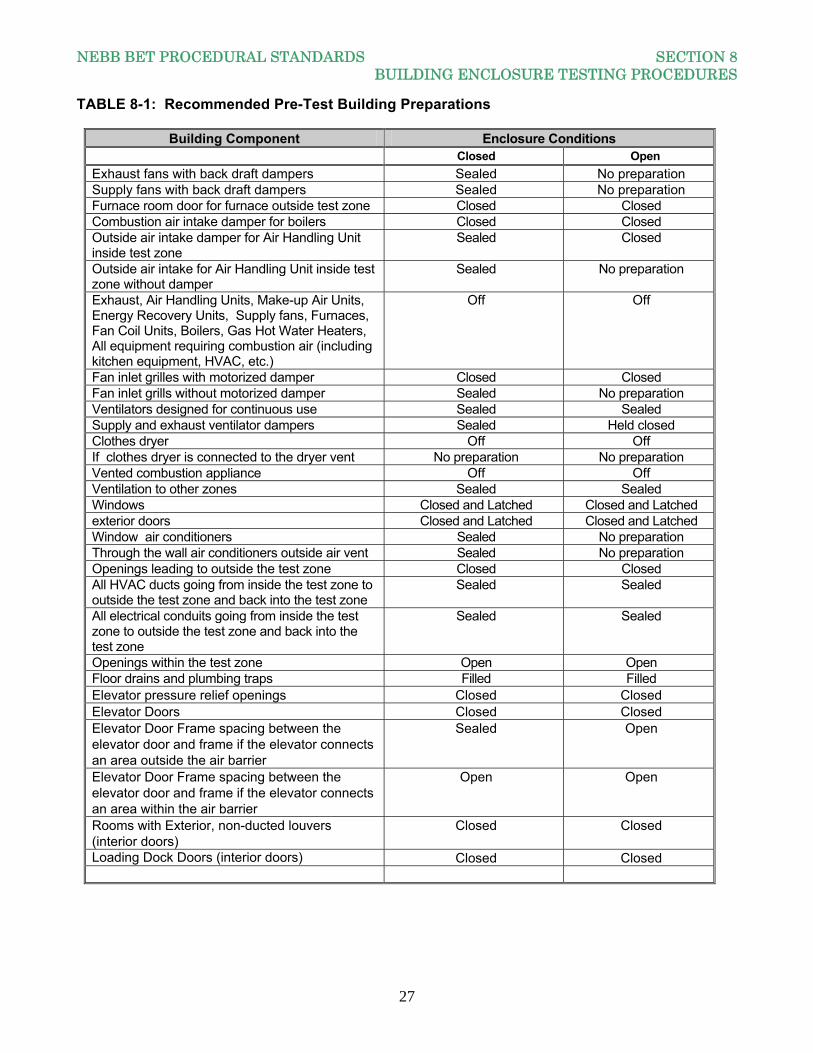
TABLE 8-1: Recommended Pre-Test Building Preparations
Building Component Enclosure Conditions Closed Open
Exhaust fans with back draft dampers Sealed No preparation Supply fans with back draft dampers Sealed No preparation Furnace room door for furnace outside test zone Closed Closed Combustion air intake damper for boilers Closed Closed Outside air intake damper for Air Handling Unit inside test zone
Sealed Closed
Outside air intake for Air Handling Unit inside test zone without damper
Sealed No preparation
Exhaust, Air Handling Units, Make-up Air Units, Energy Recovery Units, Supply fans, Furnaces, Fan Coil Units, Boilers, Gas Hot Water Heaters, All equipment requiring combustion air (including kitchen equipment, HVAC, etc.)
Off Off
Fan inlet grilles with motorized damper Closed Closed Fan inlet grills without motorized damper Sealed No preparation Ventilators designed for continuous use Sealed Sealed Supply and exhaust ventilator dampers Sealed Held closed Clothes dryer Off Off If clothes dryer is connected to the dryer vent No preparation No preparation Vented combustion appliance Off Off Ventilation to other zones Sealed Sealed Windows Closed and Latched Closed and Latched exterior doors Closed and Latched Closed and Latched Window air conditioners Sealed No preparation Through the wall air conditioners outside air vent Sealed No preparation Openings leading to outside the test zone Closed Closed All HVAC ducts going from inside the test zone to outside the test zone and back into the test zone
Sealed Sealed
All electrical conduits going from inside the test zone to outside the test zone and back into the test zone
Sealed Sealed
Openings within the test zone Open Open Floor drains and plumbing traps Filled Filled Elevator pressure relief openings Closed Closed Elevator Doors Closed Closed Elevator Door Frame spacing between the elevator door and frame if the elevator connects an area outside the air barrier
Sealed Open
Elevator Door Frame spacing between the elevator door and frame if the elevator connects an area within the air barrier
Open Open
Rooms with Exterior, non-ducted louvers (interior doors)
Closed Closed
Loading Dock Doors (interior doors) Closed Closed
NEBB BET PROCEDURAL STANDARDS SECTION 8 BUILDING ENCLOSURE TESTING PROCEDURES
28
8.2.2.9 Determine the height and temperature factor. The factor is the product of the absolute value of the indoor/outdoor air temperature difference multiplied by the building height. If the factor is less than 400 m°C (2,360 ft°F), perform the test. If the factor is greater than 400 m°C (2,360 ft°F), the stack effect may influence the building enclosure pressure difference and may reduce the accuracy of the result. When the factor is greater than the above stated values, the entire test is performed both under the pressurization and depressurization modes utilizing ASTM E1827 Standard Test Methods for Determining Airtightness of Buildings Using an Orifice Blower Door and the minimum induced test pressure is 25 Pa (0.10 in.w.c.). 8.2.2.10 Open all doors, windows, and other openings connecting portions of the building outside the test zone enclosure with the outdoors. For example, if the building is a combination of office and warehouse, and only the office portion of the building is to be tested then open the warehouse doors. If the entire office and warehouse is to be tested, then all office and warehouse doors are to be closed to the outside but the doors between the office and warehouse are to be open. 8.2.2.11 Remove sufficient ceiling tiles for lay-in ceilings, or open sufficient access panels for hard ceilings, where the pressure between the ceiling cavity and the room is equalized to within +/-10% of the building enclosure test pressure. 8.2.2.12 Record the condition of the buildings components including windows, exterior doors, interior doors, stairwell doors, elevator doors, walls, access doors, roof and floor (i.e. sealed or unsealed, open or closed, etc.). 8.2.3 BLOWER DOOR TEST METHOD PROCEDURES 8.2.3.1 Install the blower door in an entry door, window or vent opening. The openings must be sealed or taped to avoid leakage at these points. Orient the blower door appropriately for depressurization or pressurization as required. The installation has minimal obstructions of airflow into and out of the building. 8.2.3.2 Install the pressure measuring instrument across the building enclosure. It is good practice to use more than one location across the building enclosure for pressure measurement. Preferred locations for exterior pressure measurement locations are those avoiding extremes of exterior pressures. A good location avoids exterior corners and complex architectural features and is close to the middle of the exterior wall. 8.2.3.3 In addition, buildings more than four floors or 12.2 m (48.0 ft.) in height have pressures measured at a minimum of two locations or every four floors, whichever is greater. 8.2.3.4 Average ten baseline pressure points of 10 seconds per point, where the variation between any point and the mean must be no greater than 1 Pascal for an acceptable test. If the variation is greater than 1 Pascal then the test must be redone. 8.2.3.5 Zero the pressure sensor by connecting the differential ports together.
Note: Some blower doors perform this or an equivalent step automatically. Follow the manufacturer's instructions accordingly.
8.2.3.6 Before beginning the test, measure and record the baseline building differential pressure across the airflow measurement device with the blower off. If a damper is used to control airflow, it is in a fully
NEBB BET PROCEDURAL STANDARDS SECTION 8 BUILDING ENCLOSURE TESTING PROCEDURES
29
closed position for the baseline building pressure measurements. If the air moving equipment employs a blank-off plate, it is fully closed for the baseline building tests. 8.2.3.7 Start the blower door fans and pressurize / depressurize the building to the highest specified induced pressure differential. Measure and record the building enclosure differential pressure. 8.2.3.8 Pressure readings are to be taken to produce an accurate average building pressure. Fluctuations in pressure due to wind require pressure measurements to be taken on both the windward and leeward sides of the building and averaged. If the buildings height or building configuration causes internal building pressure fluctuations then interior pressure are taken and averaged. IF USING ASTM E779 Standard Test Method for Determining Air Leakage Rate by Fan Pressurization 8.2.3.9 Perform a minimum of ten building enclosure pressure differentials and the corresponding airflow measurements for both the pressurization mode and the depressurization mode (a total of twenty measurements). The measurements are taken over a minimum of 10 seconds. The range of the building enclosure pressure differences are from a minimum of 25 Pa (0.10 in.w.c.) to maximum of 75 Pa (0.30 in.w.c.). Use increments of 5 Pa (0.02 in.w.c.) for the full range of building enclosure pressure differences (i.e. 25, 35, 40, 45, 50, 55, 60, 65, 70, 75 Pa) or (0.10, 0.14, 0.16, 0.18, 0.20, 0.22, 0.24, 0.26, 0.28, and 0.30 in.w.c.). 8.2.3.10 Conduct tests at each building enclosure pressure differential. Allow the fan and instrumentation to stabilize prior to taking any measurements. At each pressure differential, measure the airflow rate and the pressure differences across the enclosure over at least a 10 second time interval. Average the airflow and pressure differentials over this time interval. For each building enclosure pressure differential test, collect data for both pressurization and de-pressurization. 8.2.3.11 After conducting the pressure tests, measure and record the baseline building differential pressure across the airflow measurement device with the fan off and sealed. 8.2.3.12 Report the building enclosure pressure differential and the airflow for each test, and the beginning and ending baseline building differential pressure. 8.2.3.13 Subtract the average baseline differential pressure from the building enclosure differential pressure and report this value for both pressurization and depressurization.
NOTE: Some equipment performs this step, or an equivalent step, automatically. Follow the manufacturer’s instructions accordingly.
8.2.3.14 Measure and record the indoor and outdoor temperatures at the end of the test so their average values can be calculated. 8.2.3.15 Repeat steps 8.2.3.9 through 8.2.3.14 for alternate pressurization. IF USING ASTM E1827 Standard Test Methods for Determining Airtightness of Buildings Using an Orifice Blower Door 8.2.3.16 Perform two building enclosure pressure differentials and the corresponding airflow measurements for both the pressurization mode and the depressurization mode (a total of four measurements). The measurements are taken over a minimum of 20 seconds and at each pressure, take five readings and average these readings.
NEBB BET PROCEDURAL STANDARDS SECTION 8 BUILDING ENCLOSURE TESTING PROCEDURES
30
8.2.3.17 Conduct tests at each building enclosure pressure differential. Allow the fan and instrumentation to stabilize prior to taking any measurements. At each pressure differential, measure the airflow rate and the pressure differences across the enclosure over at least a 20 second time interval. Average the airflow and pressure differentials over this time interval. For each building enclosure pressure differential test, collect data for both pressurization and de-pressurization. 8.2.3.18 After conducting the pressure tests, measure and record the baseline building differential pressure across the airflow measurement device with the fan off and sealed. 8.2.3.19 Report the building enclosure pressure differential, and the airflow for each test and the beginning and ending baseline building differential pressure. 8.2.3.20 Subtract the average baseline differential pressure from the building enclosure differential pressure and report this value for both pressurization and depressurization.
NOTE: Some equipment performs this step, or an equivalent step, automatically. Follow the manufacturer’s instructions accordingly.
8.2.3.21 Measure and record the indoor and outdoor temperatures at the end of the test so their average values can be calculated. 8.2.4 BUILDING AIR MOVING EQUIPMENT SYSTEM TEST METHOD PROCEDURES This test method can be used for pressurization or depressurization testing of the building enclosure, however, the test is not as accurate as the blower door tests (ASTM E779 and ASTM E1827). This test is not considered an equal to those tests. This is due to several reasons - none of which pertain to the abilities of the NEBB BET Certified Firm or the capabilities of the required instrumentation and equipment to perform the Building Air Moving Equipment Test Method. The major features which could affect the ability to perform the test and the accuracy of this test relate to the following:
1. The ability of the installed HVAC equipment and systems to mechanically bring in sufficient amounts of outside air for pressurization and / or mechanically exhaust sufficient amounts of building air for depressurization.
2. The ability of the installed mechanical equipment and systems to generate the required airflows and associated static pressures to properly conduct the test.
3. The configuration of the equipment installed in the system to accurately measure airflow and static pressures. The most accurate method to measure airflow in the field is by performing a duct traverse using a Pitot tube and digital manometer. To accurately perform a traverse measurement requires an adequate length of straight duct downstream from any equipment, fittings or obstructions to provide an ideal duct traverse plane in which to obtain an accurate duct traverse.
4. The ability of the most building air moving equipment systems to be manipulated in order to produce meaningful building pressure gradients
8.2.4.1 When using the Building Air Moving Equipment System Method Test, the NEBB BET Certified Firm follows NEBB TAB procedures to measure the airflow. The preferred method to measure the airflow is the traverse method complying with NEBB procedures. If airflow monitoring stations are used, it is the NEBB firm’s responsibility to verify the accuracy of the airflow monitor.
NEBB BET PROCEDURAL STANDARDS SECTION 8 BUILDING ENCLOSURE TESTING PROCEDURES
31
8.2.4.2 If neither the traverse method nor the use of airflow monitoring stations is available then three alternate methods of measuring airflow per the NEBB TAB procedures are used. The three different methods need to correlate flow to each other within 10%. 8.2.4.3 The Building Air Moving Equipment Test Method consists of taking two sets of data at two different building pressures. The first set of data, identified as P1, is taken the higher differential pressure value. The second set of data identified as P2, is taken the lower differential pressure value. The criteria limits for values of P1
and P2 values are as follows:
a. P1 value shall be between 75 Pa and 35 Pa (0.30 in.w.c. and 0.14 in.w.c) b. P2 value shall be 1/3 of the P1 value and shall be between 25 Pa and 10 Pa (0.10 in.w.c. and 0.04 in.w.c).
If the above criteria cannot be achieved, then the Blower Door Test Method are performed using both the pressurization and the depressurization modes. A minimum of five replicate measurements of building enclosure differential pressure and the corresponding airflow shall be taken at each value of P1 and P2. Thus, a total of ten pressure measurements and ten airflow measurements are required. 8.2.4.4 Install the pressure measuring instrument across the building enclosure. It is good practice to use more than one location across the building enclosure for pressure measurement. Preferred locations for exterior pressure measurement avoid extremes of exterior pressures. A good location avoids exterior corners and complex architectural features and is close to the middle of the exterior wall. 8.2.4.5 In addition, buildings more than four floors or 12.2 m (48.0 ft.) in height have pressures measured at a minimum of two locations or every four floors, whichever is greater. 8.2.4.6 The pressures from each location are averaged, typically using a manifold. Average the pressures over at least a 10 second time period. 8.2.4.7 Zero the pressure sensor. 8.2.4.8 Measure and record baseline building differential pressure by closing the dampers or otherwise seal off the fan(s) creating the test flows. 8.2.4.9 Conduct five tests at the P1 building enclosure pressure differential. Allow the fan and instrumentation to stabilize prior to taking any measurements. Measure the airflow and the building pressure differential simultaneously. Repeat until all five airflow measurements and five enclosure pressure differential measurements have been taken. Each of the flow and corresponding pressure differentials measurements must occur within five minutes of each other. 8.2.4.10 Repeat the entire procedure at P2 and conduct five tests at the P2 building enclosure pressure differential. Allow the fan and instrumentation to stabilize prior to taking any measurements. Measure the airflow and then measure the building pressure differential. Repeat until all five airflow measurements and five enclosure pressure differential measurements have been taken. Each of the flow and corresponding pressure differentials measurements must occur within five minutes of each other.
NEBB BET PROCEDURAL STANDARDS SECTION 8 BUILDING ENCLOSURE TESTING PROCEDURES
32
8.2.4.11 Average the five airflow measurements to each other and average the five pressure differentials to each other for the data obtained at P1. 8.2.4.12 Average the five airflow measurements to each other and average the five pressure differentials to each other for the data obtained at P2. 8.2.4.13 Measure and record Baseline Building Pressure Differential at the end of the test. 8.2.4.14 Measure and record the indoor and outdoor temperatures at the end of the test so the average values can be calculated.
NOTE: It is advisable to check the condition of the building enclosure has not changed after each pressure reading, for example, sealed openings have not become unsealed or doors, windows, or dampers have not been forced open by the building enclosure pressure testing.
8.2.5 DATA ANALYSIS AND CALCULATIONS FOR BOTH THE BLOWER DOOR TEST METHOD AND THE BUILDING AIR MOVING EQUIPMENT SYSTEM TEST METHOD 8.2.5.1 If the airflow measuring instrumentation being used does not provide the volumetric airflow at the temperature and pressure of the air flowing through the flow meter during the test, the airflow values must be corrected for density. Correct airflow for density based on the actual barometric pressure and temperature. As a guide, Tables C-1 and C-2 in Appendix C define the temperature, barometric pressure and density for Standard Air. Additionally, these tables provide the normal barometric pressure at various elevations and density correction factors for various temperatures and elevations. 8.2.5.2 When correcting the readings of the airflow measurements for density, use the temperature and barometric pressure of the air entering the fan. In the pressurization mode this will be the outside air temperature and barometric pressure. For depressurization test this will be the inside air temperature and barometric pressure. 8.2.5.3 Average the baseline building enclosure pressures measured before and after the flow measurements. Subtract the average from the measured enclosure differential pressures readings to determine the corrected induced enclosure pressures. 8.2.5.4 Plot the measured airflow against the corrected induced pressure differences on a log-log plot to complete the air leakage graph for both pressurization and de-pressurization (for an example, see Appendix C, Section C.10. 8.2.5.5 Use the data to determine the air leakage coefficient. 8.2.5.6 Correct the air leakage coefficient (C) to standard conditions. Use the data to determine the pressure exponent separately for pressurization and depressurization. 8.2.5.7 If the pressure exponent (n) is less than 0.45 or greater than 0.8, then the test is invalid and is repeated. 8.2.5.8 Use a log-linearized linear regression technique and the associated equation in Appendix C, Section C.5.5, where Q is the airflow rate, in m³/s (CFM), and P is the differential pressure in Pa (in.w.c.). In determining the fit of the above equation, the confidence intervals of the derived air leakage coefficient (C) and pressure exponent (n) are calculated.
NEBB BET PROCEDURAL STANDARDS SECTION 8 BUILDING ENCLOSURE TESTING PROCEDURES
33
8.2.5.10 The effective leakage area, AL, can be calculated from the corrected air leakage coefficient and the pressure exponent using a reference pressure (Pr). Calculate the leakage areas separately for pressurization and depressurization. 8.2.5.11 To obtain a single value for the flow coefficient, pressure exponent and leakage area after testing in both pressurization and depressurization modes, average each value from both tests. This combined data set then is used in the same way as each individual data set to obtain C, n, and AL for the combined data. If the flow at a specified pressure difference, such as 50 Pa, is desired, it is determined using the derived C and n and the specified reference pressure. 8.2.5.12 Determine the upper confidence limits for the derived values which do not exceed the leakage rate per square footage of air barrier. 8.2.6 ACCEPTANCE 8.2.6.1 The acceptance criteria are as specified in the contract documents or as agreed to between the Owner / Buyer and the NEBB BET Certified Firm. 8.2.7 REPORTING See Section 5.2.8 for reporting requirements.
8.3 BUILDING ENCLOSURE THERMOGRAPHY AND LEAK TESTING The purpose of this test, in conjunction with either the Blower Door Test Method or the Building Air Moving Equipment System Test Method, is to determine where the air leakage is occurring. Both the Blower Door Test Method and the Building Air Moving Equipment System Test Method move large amounts of air at a different temperature from the interior surface temperatures of the building’s air barrier / enclosure the local interior surface temperatures changes can be detected by thermal imaging. Air leakage creates a different infrared pattern than the normal thermal conductance of the building enclosure thus allowing for the identification of the locations where the air barriers is incomplete or has failed. If the differential temperature between inside and outside air is less than 5.5°C (10°F) a thermal image test may not adequately indicate leaks in the air barrier. Additionally, this test is to provide a qualitative analysis of the thermal effectiveness of the air barrier in cavities of walls, roofs, ceilings, and floors, framed in wood or metal. This procedure allows the detection of cavities where the air barrier may be inadequate or missing and allows identification of areas with apparently adequate air barrier. 8.3.1 INSTRUMENTS AND EQUIPMENT 8.3.1.1 All instrumentation and equipment used for this test conform to the requirements of Normative Appendix E. 8.3.1.2 A digital thermal infrared imaging system is required for this test.
8.3.2 TEST PROCEDURES 8.3.2.1 Prior to conducting the test, perform the preliminary procedures identified in Section 7.3. If the performance of these preliminary procedures is the responsibility of others, survey the site and building to insure all preliminary procedures have been properly completed. 8.3.2.2 Set the instrument gain or contrast to allow the observer to distinguish a framing member from the enclosure area around it. In addition, set the imager sensitivity so any anomalies or areas to which
NEBB BET PROCEDURAL STANDARDS SECTION 8 BUILDING ENCLOSURE TESTING PROCEDURES
34
they are referenced are not in saturation (maximum brightness or white) or in suppression (minimum brightness or black) on the display. 8.3.2.3 Verify proper operation of the recording system, if any. 8.3.2.4 Make a sketch or photograph of each enclosure area with references for locating framing members. 8.3.2.5 Utilizing the blower doors or Building Air Moving Equipment system as described in 8.2, stabilize the buildings enclosure differential pressure to P1. 8.3.2.6 A complete thermographic inspection of a building consists of an exterior or interior inspection of the complete enclosure, or both. Both types of inspection are recommended because each offers access to areas that may be difficult for the other. 8.3.2.7 Inspect all surfaces of interest from an angle as close to normal to the surface as possible, but at least at an angle that permits distinguishing framing members. Make inspections from several angles, perpendicular, if possible, and at two opposite oblique angles in order to detect the presence of reflected radiation. 8.3.2.8 Make scans from a position allowing a field of view encompassing at least two framing spaces wide and one framing space high for an interior inspection and a floor-to-ceiling height wide and one-half that distance high for an exterior inspection. 8.3.2.9 Effective corrective action requires a precise definition of the areas with apparent defects. Record each anomaly with annotation regarding the location of all recognizable building characteristics such as windows, doors, and vents. The record accommodates any requirement for calculations of enclosure areas with anomalies. Using picture in picture or fusion can make area identification easier. 8.3.3 DATA ANALYSIS AND INTERPRETATION 8.3.3.1 When performing any of the building leakage/tightness tests, the data can be analyzed using statistical methods to determine the accuracy of the measured data and subsequently compare the effectiveness of field data against those of a Pass / Fail acceptance criteria. Building leakage / tightness results are objective. Interpreting the results of thermography testing is not an objective practice but more of a subjective parameter. To minimize the subjectivity, the thermographic scans are reviewed by an individual who is thoroughly knowledgeable in interrupting thermograms. The thermography testing is done in accordance with ASTM E1186 Standard Practices for Air Leakage Site Detection in Building Envelopes and Air Barrier Systems. The interpretation of the thermogram allows determination of the following information:
a) Locations of the regions where air barrier is apparently missing or defective and the total area. b) Locations of the regions where the air barrier is apparently intact and the total area. c) Calculated total area of surfaces that cannot be inspected.
8.3.3.2 Interpretation of thermographic images requires awareness of the following types of patterns:
a) Intact air barrier: As seen from the warm side of the construction: dark parallel lines, representing the framing; uniformly lighter areas between the framing lines, representing the insulation. As seen from the cool side of the construction: the framing lines are light. The areas containing insulation are uniformly dark.
NEBB BET PROCEDURAL STANDARDS SECTION 8 BUILDING ENCLOSURE TESTING PROCEDURES
35
b) Air Barrier Failing: As seen from the warm side of the construction, the dominant effect is as described in 8.3.3.2a, except a missing air barrier shows as a well-defined dark region, as seen from the warm side and as a light region as seen from the cool side. c) Other Thermal Patterns: Irregular variation of the thermal pattern in the spaces between framing members may indicate a combination of possible causes, including varying density of insulation, convection or air leakage, moisture, or thermal bridges. A partial list of examples follows:
1) Variable density insulation often allows air leakage and convection and thereby creates intruding areas of surface temperature variation. 2) Areas where insulation contains significant moisture conduct heat much more readily than dry insulation or no insulation. Within the moist region there is a mottled and diffused thermal pattern. Temperature variations within the pattern are not extreme. 3) Thermal bridges may be caused by the presence of fasteners or framing members. 4) Air leakage, usually at joints and junctions in the building enclosure, typically produces irregular shapes with uneven boundaries and large temperature variations. Air leakage can be detected thermographically when air of a different temperature than the surface viewed comes from the side of the enclosure opposite the observer. 5) Indoor temperatures may vary from room to room. This can result in large areas showing brighter than others, as seen during an exterior survey. Independent verification of indoor temperatures can determine whether such variations are due to variations in indoor temperatures or to differences in the thermal qualities of the enclosure. 6) If an object has been removed from a surface, there may be a thermal signature where the object insulated the surface. This effect diminishes with time after removal of the object.
d) If possible, the cause of the anomalous thermal image is determined. This is done by calculations, ancillary measurements, experience, or by comparing the actual thermogram with reference thermograms for structures with known anomalies. The report substantiates such determinations.
8.3.4 ACCEPTANCE The acceptance criteria is as specified in the contract documents or as agreed to between the Owner / Buyer and the NEBB BET Certified Firm. 8.3.5 REPORTS See Section 5.2.9 for reporting requirements.
NEBB BET PROCEDURAL STANDARDS INFORMATIVE APPENDIX A SAMPLE BET SPECIFICATION
36
INFORMATIVE APPENDIX A: SAMPLE BET SPECIFICATION
(This recommended BET specification is available from www.nebb.org) NEBB recommends these BET Specifications be referenced as related documents in other appropriate sections of the project specifications.
SECTION XXXXX – BUILDING ENCLOSURE TESTING
PART1‐GENERAL 1.1 RELATED DOCUMENTS
Drawings and general provisions of the Contract, including General and Supplementary Conditions and Division 1 Specification Sections, apply to this Section.
This Section includes the testing building enclosure systems.
1.2 DEFINITIONS Acceptance Criteria:
1. The value, or range of values, compared to the measured value that determines if the test results pass or fail.
2. A test made upon completion of fabrication, receipt, installation or modification of a component unit or system to verify it meets the requirements specified.
Accuracy: The capability of an instrument to indicate the true value of a measured quantity. ACH75: The ratio of the air leakage rate at 75 Pa (0.3 in.w.c.), corrected for a standard air density, to the volume of the test zone (1/h). AHJ: The local governing Authority Having Jurisdiction over the installation. Air Barrier System: A system in the building construction that is designed and installed to reduce air leakage either into or through the building enclosure. Air Change Rate: The number of times the total air volume of a defined space is replaced in a given unit of time. Ordinarily computed by dividing the total volume of the subject space (in cubic meters or cubic feet) into the total volume of air exhausted from the space per unit of time. (For example, Air Changes per Hour (ACH)) Air Exfiltration: Air leakage out of the building or space. Air Infiltration: Air leakage into the building or space. Air Leakage Area: The effective leakage area (AL) at the test pressure.
NEBB BET PROCEDURAL STANDARDS INFORMATIVE APPENDIX A SAMPLE BET SPECIFICATION
37
Air Leakage Change Rate: Air leakage rate in volume units/h divided by the building space volume with identical volume units. (Normally expressed as air changes per hour, ACH.) Air Leakage Graph: A graphic representation showing the relationship between measured airflow rates and the corresponding measured pressure differences. (Usually plotted on a log-log scale.)
Air Leakage Rate: The total volume of air passing through the test zone or building envelope per unit of time (ft³/min [cfm] or m3/s).
Discussion: This movement includes flow through joints, cracks, and porous surfaces, or a combination thereof. The driving force for such an air leakage, in service can be mechanical pressurization and de-pressurization, natural wind pressures, or air temperature differentials between the building interior and the outdoors, or a combination thereof.
Air Leakage Site: A location on the building enclosure or air barrier system where air can move between the building interior and the outdoors. Air Tightness: The degree to which a test zone or building enclosure resists the flow of air.
Discussion: Air leakage rate, effective leakage area and the rating term such as ACH50 are examples of measures of building tightness.
Airflow Rate: The volume of airflow through the fan or blower door per unit of time (m3/s or ft³/min, CFM). Anomalous Thermal Image: An observed thermal pattern of a structure that is not in accordance with the expected thermal pattern. Baseline Building Pressure: The natural building pressure difference measured when there is no flow through the blower door. This is also referred to as the Bias Pressure. Building Enclosure: The boundary or barrier separating the interior volume of a building from the outside environment.
Discussion: For the purpose of this test procedural standards, the interior volume is the deliberately conditioned space within a building, generally not including attics, basements, and attached structures, for example, garages, unless such spaces are connected to the heating and air conditioning system, such as a crawl space plenum.
Building Pressure Difference: The pressure differential across the test zone or building enclosure. Calibrate (Calibration): The act of comparing an instrument of unknown accuracy with a standard of known accuracy to detect, correlate, report, or correct by adjustment unacceptable variation in the accuracy of the tested instrument. Certificate of Compliance (Conformance): A written statement, signed by a qualified party, attesting that the items or services are in accordance with specified requirements, and accompanied by additional information to substantiate the statement. Certification: The process of validation required to obtain a Certificate of Compliance.
NEBB BET PROCEDURAL STANDARDS INFORMATIVE APPENDIX A SAMPLE BET SPECIFICATION
38
CFM75: The airflow leakage value in cubic feet per minute at a test pressure of 75 Pascal’s (Pa). The subscript value defines the test pressure. Closed: The condition of an unoccupied building with intentional openings sealed to test the air barrier. Deficiency: Any installation, measurement, or finding outside the tolerances allowed by NEBB Procedural Standards or project specifications. Differential Pressure (P): The difference between two pressures measured between a sample point and reference point.
Discussion: This movement includes flow through joints, cracks, and porous surfaces, or a combination thereof. The driving force for such an air leakage, in service can be wind pressures, or air temperature differentials between the building interior and the outdoors, or a combination thereof.
Effective Leakage Area (ELA): In order to take values generated by fan pressurization and to use them in determining natural air exchange, the effective leakage area of a building must be calculated. Each gap and crack in the building envelope contributes a certain amount of area to the total leakage area of the building. The Effective Leakage Area assumes that all of the individual leakage areas in the building are combined into a single idealized orifice or hole. The ELA will change depending on the reference pressure used to calculate it. Enclosure: The construction, taken as a whole or in part, that separates the indoors of a building from the outdoors. Equivalent Leakage Area: EqLA, usually taken at 10 Pa using 0.61 discharge coefficient, but for the purposes of this Specification, it is taken at 75 Pa. Field-of-View (FOV): The total angular dimensions, expressed in degrees or radians, within which objects can be imaged, displayed, and recorded by a stationary imaging device. Framing Spacing: Distance between the centerlines of joists, studs, or rafters. Function: The particular type of data measurement specified in NEBB Standards for Instrumentation and Calibration. Infrared Imaging System: An instrument that converts the spatial variations in infrared radiance from a surface into a two-dimensional image of that surface, in which variations in radiance are displayed as a range of colors or tones. Infrared Thermography: The process of generating thermal images that represent temperature and emittance variations over the surfaces of objects. Instantaneous Field of View (IFOV): The smallest angle, in milliradians, that can be instantaneously resolved by a particular infrared imaging system. Intentional Opening: Openings within the envelope designed to remain open to atmosphere during the buildings operation. Intentional openings include air intake, exhaust louvers, pressure relief dampers or louvers, dryer and exhaust vents, combustion flues and any other leakage site designed to remain
NEBB BET PROCEDURAL STANDARDS INFORMATIVE APPENDIX A SAMPLE BET SPECIFICATION
39
open during the buildings normal operation. Windows, doors, conduits, mechanical piping, sleeves and structural steel are not considered intentional openings. M³/S75: The airflow leakage value in cubic meters per second at a test pressure of 75 Pascal’s (Pa). The subscript value defines the test pressure. Masonry Veneer: Frame construction with a non-load bearing exterior masonry surface. May: Used to indicate a course of action that is permissible as determined by the NEBB BET Certified Firm. Minimum Resolvable Temperature Difference (MRTD): A measure of the ability of the operators of an infrared imaging system to discern temperature differences with that system. The MRTD is the minimum temperature difference between a four-slot test pattern of defined shape and size and its blackbody background at which an average observer can discriminate the pattern with that infrared imaging system at a defined distance.
N/A: Not Available, Not Applicable, or Not Accessible. The simple notation “N/A” without definition is not allowed.
NEBB BET Certified Firm: A firm that has met and maintains all the requirements of the National Environmental Balancing Bureau for firm certification in Building Envelope Testing and is currently certified by NEBB. A NEBB BET Certified Firm shall employ at least one NEBB BET Certified Professional in a full time management position. NEBB BET Certified Professional: A full time employee of the firm in a management position who has successfully passed the professional level written and practical qualification examinations and maintains the professional re-qualification requirements of NEBB. NEBB Certified BET Report: The data presented in a NEBB Certified BET Report accurately represents system measurements obtained in accordance with the current edition of the NEBB Procedural Standards for Building Envelope Testing. A NEBB Certified BET Report does not necessarily guarantee that systems measured conform to the design requirements or stated guidelines. The report is an accurate representation of the measured results only. Nominal Airflow Rate: The flow rate indicated by the blower door using the manufacturer's calibration coefficients (m3/s or ft³/min, CFM). Orifice Blower Door: A blower door in which airflow rate is determined by means of the pressure drop across an orifice or nozzle. Open: The condition of a building used to test the ventilation rate in a occupied building with intentional openings unsealed. Precision: The ability of an instrument to produce repeatable readings of the same quantity under the same conditions. The precision of an instrument refers to its ability to produce a tightly grouped set of values around the mean value of the measured quantity. Precision Index of the Average: The sample standard deviation divided by the square root of the number of samples. Pressure Station: A specified induced change in the building pressure difference from the initial zero-flow building pressure difference (Pa, in.w.c.).
NEBB BET PROCEDURAL STANDARDS INFORMATIVE APPENDIX A SAMPLE BET SPECIFICATION
40
PPM: Parts per million. Procedure: A defined approach that outlines the execution of a sequence of work or operations. Procedures are used to produce repeatable and defined results. Range: The upper and lower limits of an instrument’s ability to measure values for which the instrument is calibrated. Resolution:
1. The smallest change in a measured variable that an instrument can detect. 2. The implementation of actions that correct a tested or observed deficiency.
Shall: Indicates mandatory requirements to be followed in order for the project to become a NEBB certified project. Work must conform to these standards and procedures and no deviation is permitted. Note: In the event unique circumstances prevent a required action from being fulfilled, a notation shall be included in the report explaining the reason the requirement was not completed. For example, such notation could be: Not Available, Not Applicable, or Not Accessible. The simple notation “N/A” without definition is not allowed.
Should: Indicate a certain course of action is preferred but not necessarily required.
Single Zone: A space where the pressure difference between any two places vary by no more than 5% of the inside to outside pressure difference.
Discussion: A multi-room space that is interconnected within itself with door-sized openings through any partitions or floors is likely to satisfy this criterion if the fan airflow rate is less than 3 m³/s (6357 ft³/min).
Specified Test Pressure: The required induced differential static air pressure across the specimen. Standard: A required qualification, action, or result. Standard Operating Procedure (SOP):
1. An internal policy prepared by the Certified Firm or prepared by the Owner. Procedures are written to provide guidance, direction, and step-by-step details relating to issues such as safety, testing protocols, acceptance criteria, etc. Use NEBB Certified Firm SOP in absence of SOP prepared by the Owner.
2. Established procedure to be followed in carrying out a given operation or in a given situation. Test Pressure Difference (Differential): The measured pressure difference across the building envelope, expressed in Pascals (Pa) or inches of water column (in.w.c.). Test Zone: A building, or a portion of a building, configured as a single zone. For detached dwellings, the test zone envelope normally comprises the thermal envelope. Test Zone Enclosure: The barrier or series of barriers between a test zone and the outdoors and internal spaces not included in the test zone.
NEBB BET PROCEDURAL STANDARDS INFORMATIVE APPENDIX A SAMPLE BET SPECIFICATION
41
Testing: The use of specialized and calibrated instruments to measure parameters such as temperature, pressure, vapor flow, airflow, fluid flow, fluid quantities, rotational speed, electrical characteristics, velocity, sound and vibration level, air and hydronic quantities, and other data in order to determine performance, operation, or function. Testing, Adjusting, and Balancing (TAB): A systematic process or service applied to heating, ventilating and air-conditioning (HVAC) systems and other environmental systems to achieve and document air and hydronic flow rates. The standards and procedures for providing these services are addressed in the current edition of the NEBB Procedural Standards for the Testing, Adjusting and Balancing of Environmental Systems. Thermal Pattern: A representation of colors or tones that indicate surface temperature and emittance variation. Thermogram: A recorded image that maps the apparent temperature pattern of an object or scene into a corresponding contrast or color pattern. Total Airflow: The volume of air flowing per unit of time through the test zone inclusive of the air flowing through the test zone under differential test pressure conditions converted to standard conditions for temperature and density. Unit of Length: The sum of all perimeters of operable ventilators, sash, or doors that are contained in the test specimen based on overall dimensions of such parts. Where two such operable parts meet two adjacent lengths of perimeter shall be counted as only one length. Zone: A volume of building served by a single ventilation system. For buildings with natural ventilation only, the whole building is considered a zone. 1.3 BET FIRM QUALIFICATIONS The BET Firm is NEBB Certified in Building Enclosure Testing. Building enclosure testing is conducted by the NEBB BET Certified Professional or by technicians directly under the supervision of the NEBB BET Certified Professional.
1.4 BET FIRM SUBMITTALS 1.4.1 Qualification Data: When requested, submit 2 copies of evidence that BET firm and this Project's BET team members meet the qualifications specified in Sub-section 1.3 BET Firm Qualifications. 1.4.2 BET Agenda: When requested, submit 2 copies of the BET Agenda. Include a complete set of report forms intended for use on this Project. 1.4.3 BET Certified Reports: Submit a final BET report in accordance with the current edition of the NEBB Procedural Standards for Building Enclosure Testing.
1.5 QUALITY ASSURANCE 1.5.1 The NEBB BET Certified Firm submits a copy of the firm's NEBB BET Certification.
1.5.2 When requested, the NEBB BET Certified Firm provides the NEBB Certificate of Conformance Certification.
NEBB BET PROCEDURAL STANDARDS INFORMATIVE APPENDIX A SAMPLE BET SPECIFICATION
42
1.5.3 BET Report Forms: Prepare report forms in accordance with the requirements from the current edition of the NEBB Procedural Standards for Building Enclosure Testing.
1.5.4 Instrumentation Calibration: Calibration of instruments is in accordance with the current edition of the NEBB Procedural Standards for Building Enclosure Testing. 1.6 CONSTRUCTION TEAM RESPONSIBILITY TO BET AGENCY 1.6.1 Provide the NEBB BET Certified Firm with a conformed set of contract documents pertaining to the air barrier (drawings, specifications, and approved submittals), including all current approved change orders and contract modifications. 1.6.2 Develop a project schedule with the input of the NEBB BET Certified Firm that coordinates the work of other disciplines and provides adequate time in the construction process to allow successful completion of the building enclosure testing and remedial work. 1.6.3 Notify the NEBB BET Certified Firm of all schedule changes.
1.6.4 Ensure the building enclosure is complete, including but not limited to, all structural components, the air barrier and vapor barrier complete, windows and doors installed, door hardware complete, door sweeps and weather stripping complete, floor and ceilings complete. Ensure the building enclosure and components are complete and operational such that the performance of the building enclosure tests would not be adversely affected. 1.6.5 Provide all project preparation and setup for the BET tests, this includes, but is not limited to, temporary sealing of intentional openings, removing ceiling tile, opening access doors, opening interior doors and affixing them so they cannot close during the tests. This includes preparation of adjoining spaces. This would also include staging the building so no people will be opening doors or windows during the BET tests. 1.6.6 Provide temporary or permanent power for BET tests. 1.6.7 For building pressure test method using the Building Air Moving Equipment systems:
a. Ensure all necessary building systems are complete and are operating in a safe manner. b. Complete the installation of permanent electrical power systems serving the building systems.
Such electrical systems are properly installed in accordance with all applicable codes to ensure the safety of all construction personnel.
c. Perform start-up of all building systems in accordance with manufacturers' recommendations. d. Complete the installation, programming, calibration and startup of all building control systems.
PART 2 - PRODUCTS (Not Applicable)
PART 3 – EXECUTION 3.1 EXAMINATION Examine the Contract Documents to become familiar with Project requirements and to discover conditions in systems' designs that precludes proper BET of systems and equipment. Contract Documents are defined in the General and Supplementary Conditions of Contract. Report deficiencies discovered.
NEBB BET PROCEDURAL STANDARDS INFORMATIVE APPENDIX A SAMPLE BET SPECIFICATION
43
3.2 PRELIMINARY PROCEDURES FOR BUILDING ENCLOSURE TESTING Conduct the Preliminary Procedures in accordance with procedures contained in the current edition of the NEBB Procedural Building Enclosure Testing and this section. This includes the Design Professionals and/or the Owner are responsible to define the objectives and the acceptance criteria for the testing. Additionally, they are responsible to define which air leakage test(s) are to be performed by the NEBB BET Certified Firm. 3.3 INSTRUMENTS AND EQUIPMENT Instruments and equipment necessary to perform Building Enclosure Testing meet the requirements of the current edition of the NEBB Procedural Building Enclosure Testing and this section. 3.4 COMMON TEST PROCEDURES FOR BUILDING ENCLOSURE TESTING Perform Building Enclosure Testing on all systems to be tested according to the procedures contained in the current edition of the NEBB Procedural Building Enclosure Testing and this section. As stated in Section 3.1 above, the test method is defined by the Design Professionals and /or the Owner. The procedures listed below apply to both test methods and is followed when performing either the Blower Door Test Method or the Building Air Moving Equipment System Test method. 3.4.1 Establish the exterior test zone enclosure. This is accomplished by defining the test zone enclosure and ensuring it is appropriate for the goals of the test. 3.4.2 Select the appropriate test enclosure condition; open or closed. For the closed condition, close all operable openings and seal other intentional openings to evaluate enclosure air tightness. For the open condition, leave all operable openings in the normal operating condition of the building’s occupancy to assess the enclosure's effect on natural air change rates. The closed condition is the default option if no compelling reason exists to use the open condition. 3.4.3 Adjust all building components in accordance with Table 1 below and/or per the specification. For testing a building in the closed condition, close all operable openings and seal other intentional openings to evaluate enclosure air tightness. For occupied condition, leave all operable openings in the normal operating condition of the building’s occupancy. 3.4.4 Prior to conducting the test, perform the preliminary procedures identified in Section 3.1. If the performance of these preliminary procedures is the responsibility of others, survey the site and building to insure all preliminary procedures have been properly completed. 3.4.5 Establish the interior test zone. This is accomplished by opening all interior building doors including fire doors, corridor doors, and pass-through in the test zone so a uniform inside pressure is created within the zone. If there are hard ceilings with access doors, all access doors are to be open. 3.4.6 Measure and record the wind velocity and direction on the windward side of the building at a distance 30 to 50 feet away from the buildings. Preferred test conditions are wind velocity of 0 to 2 m/s (0 to 4 mph). If the surrounding building induced winds or the wind is gusting more than 4 mph above the steady state wind the windspeed is noted in the report. 3.4.7 Measure and record the outside temperature. Preferred test conditions are outside temperatures from 2°C to 35°C (35°F to 95°F). If test is performed below 2°C (35°F) there is a possibility of freezing pipes. If the test is performed above 35°C (95°F) damaging finished materials, building finishes or worker safety becomes a concern.
NEBB BET PROCEDURAL STANDARDS INFORMATIVE APPENDIX A SAMPLE BET SPECIFICATION
44
3.4.8 Measure and record the indoor and outdoor temperatures at the beginning of the test so the average values can be calculated. 3.4.9 Determine the height & temperature factor. The factor is the product of the absolute value of the indoor/outdoor air temperature difference multiplied by the building height. If the factor is less than 400 m°C (2,360 ft°F), perform the test. If the factor is greater than 400 m°C (2,360 ft°F), the stack effect may influence the building enclosure pressure difference and will reduce the accuracy of the result. When the factor is greater than the above stated values, the entire test is performed both under a pressurization and depressurization modes using ASTM E 1827 Blower Door Test Method. The minimum induced test pressure is 25 Pa (0.10 in.w.c.).
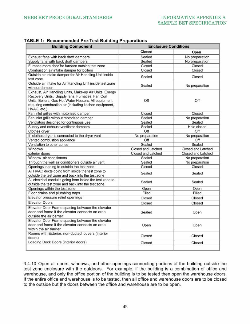
NEBB BET PROCEDURAL STANDARDS INFORMATIVE APPENDIX A SAMPLE BET SPECIFICATION
45
TABLE 1: Recommended Pre-Test Building Preparations Building Component Enclosure Conditions
Closed OpenExhaust fans with back draft dampers Sealed No preparation Supply fans with back draft dampers Sealed No preparation Furnace room door for furnace outside test zone Closed Closed Combustion air intake damper for boilers Closed Closed Outside air intake damper for Air Handling Unit inside test zone
Sealed Closed
Outside air intake for Air Handling Unit inside test zone without damper
Sealed No preparation
Exhaust, Air Handling Units, Make-up Air Units, Energy Recovery Units, Supply fans, Furnaces, Fan Coil Units, Boilers, Gas Hot Water Heaters, All equipment requiring combustion air (including kitchen equipment, HVAC, etc.)
Off Off
Fan inlet grilles with motorized damper Closed Closed Fan inlet grills without motorized damper Sealed No preparation Ventilators designed for continuous use Sealed Sealed Supply and exhaust ventilator dampers Sealed Held closed Clothes dryer Off Off If clothes dryer is connected to the dryer vent No preparation No preparation Vented combustion appliance Off Off Ventilation to other zones Sealed Sealed Windows Closed and Latched Closed and Latched exterior doors Closed and Latched Closed and Latched Window air conditioners Sealed No preparation Through the wall air conditioners outside air vent Sealed No preparation Openings leading to outside the test zone Closed Closed All HVAC ducts going from inside the test zone to outside the test zone and back into the test zone
Sealed Sealed
All electrical conduits going from inside the test zone to outside the test zone and back into the test zone
Sealed Sealed
Openings within the test zone Open Open Floor drains and plumbing traps Filled Filled Elevator pressure relief openings Closed Closed Elevator Doors Closed Closed Elevator Door Frame spacing between the elevator door and frame if the elevator connects an area outside the air barrier
Sealed Open
Elevator Door Frame spacing between the elevator door and frame if the elevator connects an area within the air barrier
Open Open
Rooms with Exterior, non-ducted louvers (interior doors) Closed Closed
Loading Dock Doors (interior doors) Closed Closed
3.4.10 Open all doors, windows, and other openings connecting portions of the building outside the test zone enclosure with the outdoors. For example, if the building is a combination of office and warehouse, and only the office portion of the building is to be tested then open the warehouse doors. If the entire office and warehouse is to be tested, then all office and warehouse doors are to be closed to the outside but the doors between the office and warehouse are to be open.
NEBB BET PROCEDURAL STANDARDS INFORMATIVE APPENDIX A SAMPLE BET SPECIFICATION
46
3.4.11 Remove sufficient ceiling tiles for lay-in ceilings, or open sufficient access panels for hard ceilings, were the pressure between the ceiling cavity and the room is equalized to within +/-10% of the building enclosure test pressure. 3.4.12 Record the condition of the buildings components including windows, exterior doors, interior doors, stairwell doors, elevator doors, walls, access doors, roof and floor (i.e. sealed or unsealed, open or closed, etc.).
If using ASTM E779 Standard Test Method for Determining Air Leakage Rate by Fan Pressurization 3.4.13 Perform a minimum of ten building enclosure pressure differentials and the corresponding airflow measurements for both the pressurization mode and the depressurization mode (a total of t measurements). The measurements are taken over a minimum of 10 seconds. The range of the building enclosure pressure differences should be from a minimum of 25 Pa (0.10 in.w.c.) to maximum of 75 Pa (0.30 in.w.c.). Use increments of 5 Pa (0.02 in.w.c.) for the full range of building enclosure pressure differences (i.e. 25, 35, 40, 45, 50, 55, 60, 65, 70, 75 Pa) or (0.10, 0.14, 0.16, 0.18, 0.20, 0.22, 0.24, 0.26, 0.28, and 0.30 in.w.c.). 3.4.14 Conduct tests at each building enclosure pressure differential. Allow the fan and instrumentation to stabilize prior to taking any measurements. At each pressure differential, measure the airflow rate and the pressure differences across the enclosure over at least a 10 second time interval. Average the airflow and pressure differentials over this time interval. For each building enclosure pressure differential test, collect data for both pressurization and de-pressurization. 3.4.15 After conducting the pressure tests, measure and record the baseline building differential pressure across the airflow measurement device with the fan off and sealed. 3.4.16 Report the building enclosure pressure differential, and the airflow for each test and the beginning and ending baseline building differential pressure. 3.4.17 Subtract the average baseline differential pressure from the building enclosure differential pressure and report this value for both pressurization and depressurization.
NOTE: Some equipment performs this step, or an equivalent step, automatically. Follow the manufacturer’s instructions accordingly.
3.4.18 Measure and record the indoor and outdoor temperatures at the end of the test so the average values can be calculated. 3.4.19 Repeat steps 3.4.13 through 3.4.18 for the alternate pressurization. IF USING ASTM E1827 Standard Test Methods for Determining Airtightness of Buildings Using an Orifice Blower Door 3.4.20 Perform two building enclosure pressure differentials and the corresponding airflow measurements for both the pressurization mode and the depressurization mode (a total of four measurements). The measurements are taken over a minimum of 20 seconds and at each pressure, take five readings and average these readings. The range of the building enclosure pressure differences should be from a minimum of 25 Pa (0.10 in.w.c.) to maximum of 75 Pa (0.30 in.w.c.). 3.4.21 Conduct tests at each building enclosure pressure differential. Allow the fan and instrumentation to stabilize prior to taking any measurements. At each pressure differential, measure the airflow rate
NEBB BET PROCEDURAL STANDARDS INFORMATIVE APPENDIX A SAMPLE BET SPECIFICATION
47
and the pressure differences across the enclosure over at least a 20 second time interval. Average the airflow and pressure differentials over this time interval. For each building enclosure pressure differential test, collect data for both pressurization and de-pressurization. 3.4.22 After conducting the pressure tests, measure and record the baseline building differential pressure across the airflow measurement device with the fan off and sealed. 3.4.23 Report the building enclosure pressure differential, and the airflow for each test and the beginning and ending baseline building differential pressure. 3.4.24 Subtract the average baseline differential pressure from the building enclosure differential pressure and report this value for both pressurization and depressurization.
NOTE: Some equipment performs this step, or an equivalent step, automatically. Follow the manufacturer’s instructions accordingly.
3.4.25 Measure and record the indoor and outdoor temperatures at the end of the test so the average values can be calculated. 3.5 BLOWER DOOR TEST METHOD PROCEDURES 3.5.1 Install the blower door in an entry door, window or vent opening. The openings must be sealed or taped to avoid leakage at these points. Orient the blower door appropriately for depressurization or pressurization as required. The installation should have minimal obstructions of airflow into and out of the building. 3.5.2 Install the pressure measuring instrument across the building enclosure. It is good practice to use more than one location across the building enclosure for pressure measurement. Preferred locations for exterior pressure measurement locations should be those avoiding extremes of exterior pressures. A good location avoids exterior corners and complex architectural features and should be close to the middle of the exterior wall. 3.5.3 In addition, buildings more than four floors or 12.2m (48.0 ft.) in height have pressures measured at a minimum of two locations or every four floors, whichever is greater. 3.5.4 Average ten baseline pressures points of 10 seconds per point, where the variation between any point and the mean must be no greater than 1 Pascal. 3.5.5 Zero the pressure sensor by connecting the differential ports together.
Note: Some blower doors perform this or an equivalent step automatically. Follow the manufacturer's instructions accordingly.
3.5.6 Before beginning the test, measure and record the baseline building differential pressure across the airflow measurement device with the blower off. If a damper is used to control airflow, it should be in a fully closed position for the baseline building pressure measurements. If the air moving equipment employs a blank-off plate, it should be fully closed for the baseline building tests. 3.5.7 Start the blower door fans and pressurize / depressurize the building to the highest specified induced pressure differential. Measure and record the building enclosure differential pressure.
NEBB BET PROCEDURAL STANDARDS INFORMATIVE APPENDIX A SAMPLE BET SPECIFICATION
48
3.5.8 Pressure readings are to be taken to produce an accurate average building pressure. Fluctuations in pressure due to wind require pressure measurements to be taken on both the windward and leeward side of the building and averaged. If the buildings height or building configuration causes internal building pressure fluctuations then interior pressure are taken and averaged.
3.6 BUILDING AIR MOVING EQUIPMENT SYSTEM TEST METHOD PROCEDURES This test method can be used for pressurization or depressurization testing of the building enclosure, however, the test is not as accurate as the blower door tests (ASTM E779 or ASTM E1827). This test should not be considered an equal to those tests. This is due to several reasons; none of which pertain to the abilities of the NEBB BET Certified Firm or the capabilities of the required instrumentation and equipment to perform the Building Air Moving Equipment Test Method. The major features which could affect the ability to perform the test and the accuracy of this test relate to the following:
a. The ability of the installed HVAC equipment and systems to mechanically bring in sufficient amounts of outside air for pressurization and / or mechanically exhaust sufficient amounts of building air for depressurization.
b. The ability of the installed mechanical equipment and systems to generate the required airflows and associated static pressures to properly conduct the test
c. The configuration of the equipment installed in the system to accurately measure airflow and static pressures. The most accurate method to measure airflow in the field is by performing a duct traverse using a Pitot tube and digital manometer. To accurately perform a traverse measurement requires an adequate length of straight duct downstream from any equipment, fittings or obstructions to provide an ideal duct traverse plane in which to obtain an accurate duct traverse.
d. The ability of the most building air moving equipment systems to be manipulated in order to produce meaningful building pressure gradients
3.6.1 When using the Building Air Moving Equipment System Method Test, the NEBB BET Certified Firm follows NEBB TAB procedures to measure the airflow. The preferred method to measure the airflow is by the traverse method complying with NEBB procedures. If airflow monitoring stations are used, it is the NEBB firm’s responsibility to verify the accuracy of the airflow monitor. 3.6.2 If neither the traverse method nor the use of airflow monitoring stations is available then three alternate methods of measuring airflow per the NEBB TAB procedures are used. The three different methods should correlate flow to each other within 10%. 3.6.3 The Building Air Moving Equipment Test Method consists of taking two sets of data at two different building pressures. The first set of data, identified as P1, is taken the higher differential pressure value. The second set of data identified as P2, is taken the lower differential pressure value. The criteria limits for values of P1 and P2 values are as follows:
a. P1 value is between 75 Pa and 35 Pa (0.30 in.w.c. and 0.14 in.w.c). b. P2 value is 1/3 of the P1 value and is between 25 Pa and 10 Pa (0.10 in.w.c. and 0.04 in.w.c).
If the above criteria cannot be achieved, then the Blower Door Test Method is performed using both the pressurization and the depressurization modes.
A minimum of five replicate measurements of building enclosure differential pressure and the corresponding airflow are taken at each value of P1 and P2. Thus, a total of ten pressure measurements and ten airflow measurements are required.
NEBB BET PROCEDURAL STANDARDS INFORMATIVE APPENDIX A SAMPLE BET SPECIFICATION
49
3.6.4 Install the pressure measuring instrument across the building enclosure. It is good practice to use more than one location across the building enclosure for pressure measurement. Preferred locations for exterior pressure measurement locations should be those avoiding extremes of exterior pressures. A good location avoids exterior corners and complex architectural features and should be close to the middle of the exterior wall. 3.6.5 In addition, buildings more than four floors or 12.2m (48.0 ft.) in height have pressures measured at a minimum of two locations or every four floors, whichever is greater. 3.6.6 The pressures from each location should be averaged, typically using a manifold. Average the pressures over at least a 10 second time period. 3.6.7 Zero the pressure sensor 3.6.8 Measure and record the baseline building differential pressure by closing the dampers or otherwise seal off the fan(s) creating the test flows. 3.6.9 Conduct five tests at the P1 building enclosure pressure differential. Allow the fan and instrumentation to stabilize prior to taking any measurements. Measure the airflow and the building pressure differential simultaneously. Repeat until all five airflow measurements and five enclosure pressure differential measurements have been taken. Each of the flow and corresponding pressure differentials measurements must occur within five minutes of each other. 3.6.10 Repeat the entire procedure at P2 and conduct five tests at the P2 building enclosure pressure differential. Allow the fan and instrumentation to stabilize prior to taking any measurements. Measure the airflow and then measure the building pressure differential. Repeat until all five airflow measurements and five enclosure pressure differential measurements have been taken. Each of the flow and corresponding pressure differentials measurements must occur within five minutes of each other. 3.6.11 Average the five airflow measurements to each other and average the five pressure differentials to each other for the data obtained at P1. 3.6.12 Average the five airflow measurements to each other and average the five pressure differentials to each other for the data obtained at P2. 3.6.13 Measure and record Baseline Building Pressure Differential at the end of the test. 3.6.14 Measure and record the indoor and outdoor temperatures at the end of the test so the average values can be calculated.
NOTE: It is advisable to verify the condition of the building enclosure has not changed after each pressure reading. For example, sealed openings have not become unsealed or doors, windows, or dampers have not been forced open by the building enclosure pressure testing.
3.7 DATA ANALYSIS AND CALCULATIONS FOR BOTH THE BLOWER DOOR TEST METHOD AND THE BUILDING AIR MOVING EQUIPMENT SYSTEM TEST METHOD 3.7.1 If the airflow measuring instrumentation being used does not provide the volumetric airflow at the temperature and pressure of the air flowing through the flow meter during the test, the airflow values must be corrected for density.
NEBB BET PROCEDURAL STANDARDS INFORMATIVE APPENDIX A SAMPLE BET SPECIFICATION
50
3.7.2 When correcting the readings of the airflow measurements for density, the preferred method is to use the temperature and the actual barometric pressure. A method to correct for density using temperature and elevation is available, but does not account for weather impact. In the pressurization mode this will be the outside air temperature and barometric pressure. For depressurization test this will be the inside air temperature and barometric pressure. 3.7.3 Average the baseline building enclosure pressures measured before and after the flow measurements. Subtract the average from the measured enclosure differential pressures readings to determine the corrected induced enclosure pressures. 3.7.4 Plot the measured airflow against the corrected induced pressure differences on a log-log plot to complete the air leakage graph for both pressurization and de-pressurization (for an example, see Appendix C, Section C.10 of the current edition of the NEBB Procedural Building Enclosure Testing. 3.7.5 Use the data to determine the air leakage coefficient. 3.7.6 Correct the air leakage coefficient (C) to standard conditions. Use the data to determine the pressure exponent separately for pressurization and depressurization. 3.7.7 If the pressure exponent (n) is less than 0.45 or greater than 0.8, then the test is invalid and is repeated. 3.7.8 Use a log-linearized linear regression technique and the associated equation in Appendix C, Section C.5.5 of the current edition of the NEBB Procedural Building Enclosure Testing, where Q is the airflow rate, in m³/s (CFM), and P is the differential pressure in Pa (in.w.c.). In determining the fit of the above equation, the confidence intervals of the derived air leakage coefficient (C) and pressure exponent (n) should be calculated. 3.7.9 The effective leakage area, AL, can be calculated from the corrected air leakage coefficient and the pressure exponent using a reference pressure (Pr). Calculate the leakage areas separately for pressurization and depressurization. 3.7.10 To obtain a single value for flow coefficient, pressure exponent and leakage area for use in other calculations, the average of these values from the pressurization and depressurization enclosure flows and pressure differences, with the offsets removed, may be combined together. This combined data set then is used in the same way as each individual data set to obtain C, n, and AL for the combined data. If the flow at a specified pressure difference, such as 50 Pa, is desired, it should be determined using the derived C and n and the specified reference pressure. 3.7.11 Determine the upper confidence limits for the derived values which does not exceed the leakage rate per square footage of air barrier. 3.8 ACCEPTANCE The acceptance criteria should be as specified in the contract documents or as agreed to between the Owner / Buyer and the NEBB BET Certified Firm. 3.9 FINAL REPORT The final report is in accordance with the requirements of the current edition of the NEBB Procedural Standards for the Building Enclosure Testing.
NEBB BET PROCEDURAL STANDARDS INFORMATIVE APPENDIX B REFERENCES AND REFERENCED PUBLICATIONS
51
INFORMATIVEAPPENDIXB:REFERENCESANDREFERENCEDPUBLICATIONS American Society of Heating, Refrigerating and Air Conditioning Engineers (ASHRAE) 1791 Tullie Circle Northeast, Atlanta, Georgia 30329 ASHRAE Handbook—HVAC Applications Chapter on HVAC Commissioning Chapter on Building Enclosure ASHRAE Handbook—HVAC Fundamentals Chapters on Heat, Air & Moisture Control in Buildings American Society for Testing and Materials (ASTM) International 100 Barr Harbor Drive, West Conshohocken, Pennsylvania 19428 ASTM C-168 Terminology Relating to Thermal Insulation ASTM E-456 Terminology Relating to Quality and Statistics ASTM E-631 Terminology of Building Construction ASTM E-741 Test Method for Determining Air Change in a Single Zone by Means of a
Tracer Gas. ASTM E-779 Test Method for Determining Air Leakage Rate by Fan Pressurization ASTM E-783 Standard test Method for Field Measurements of Air Leakage Through
Installed Exterior Windows and Doors ASTM C-1060 Standard Practice for Thermographic Inspection of Insulation Installations
in Enclosure Cavities of Frame Buildings ASTM E-1105 Standard Test Method for Field Determination of Water Penetration of
Installed Exterior Windows and Doors by Uniform of Cyclic Static Air Pressure Difference ASTM C-1153 Standard Practice for Location of Wet Insulation in Roofing Systems Using
Infrared Imaging ASTM E-1186 Practices for Air Leakage Site Detection in Building Enclosures and Air
Barriers
ASTM E-1213 Test Method for Minimum Resolvable Temperature Difference for Thermal Imaging Systems
ASTM E-1258 Test Method for Airflow Calibration of Fan Pressurization Devices
NEBB BET PROCEDURAL STANDARDS INFORMATIVE APPENDIX B REFERENCES AND REFERENCED PUBLICATIONS
52
ASTM E-1827 Standard Test Methods for Determining Airtightness of Buildings Using an Orifice Blower Door
ANSI/ASTM PTC 19.1-Part 1 Measurement Uncertainty, Instruments, and Apparatus
International Organization for Standardization (ISO)
ISO Central Secrétariats, 1, ch. de la Voie-Creuse, CP 56, CH-1211 Geneva 20 Switzerland
ISO 9972 Thermal Insulation-Determination of Building Airtightness-Fan
Pressurization Method National Environmental Balancing Bureau (NEBB) 8575 Grovemont Circle, Gaithersburg, Maryland 20877 Procedural Standards for Whole Building Systems Technical Commissioning of
New Construction This manual serves a comprehensive guide for commissioning building systems. The text
describes the commissioning process, organization, planning, procedures and methods for verifying and documenting the performance of building systems. There are focus section on the commissioning of HVAC, Plumbing and Fire Protection Systems.
Procedural Standards for Retro-Commissioning of Existing Building This manual serves a comprehensive guide for commissioning building systems. The text
describes the retro-commissioning process, organization, planning, procedures and methods for verifying and documenting the performance of existing building systems.
Procedural Standards for Certified Testing of Cleanrooms This manual provides an extensive array of information on cleanroom testing, technology
and test procedures. It includes: standards issues dealing with the NEBB Cleanroom program, requirements of the Certified CPT Firm, Certified CPT Professionals, instrumentation requirements, reporting requirements, standard operating procedures and exacting procedural issues for all primary and secondary cleanroom tests. Also included is a sample specification, listing of cleanroom references, and engineering and statistical data and examples.
Study Course for Certified Testing of Cleanrooms This is a self-study course in cleanrooms, cleanroom design and systems including
cleanroom testing equipment, control systems, cleanroom test procedures and cleanroom equipment and accessories. The package includes multiple lessons plus a study course examination, reference material and associated engineering and statistical materials.
Procedural Standards for Fume Hood Performance Testing This manual provides a basis for the fume hood testing program by providing Certified Firm
and Certified Professional requirements, instrumentation and reporting requirements and step-by-step testing procedures in evaluating fume hood performance. It also includes a sample specification, references, and sample reporting forms.
Procedural Standards for the Measurement of Sound and Vibration This publication provides step-by-step comprehensive guidance for obtaining and
recording sound and vibration data on HVAC systems. Topics include: instrumentation,
NEBB BET PROCEDURAL STANDARDS INFORMATIVE APPENDIX B REFERENCES AND REFERENCED PUBLICATIONS
53
inspection of building construction and conditions, interior and exterior sound measurement, and vibration measurement procedures. Also covered are sample specifications and sample reporting forms.
Sound and Vibration Design and Analysis A concise coverage of sound and vibration as it relates to HVAC systems. Basic concepts
of the science of sound and vibration are covered, plus the most current information on equipment sound levels, duct element regenerated and sound power and attenuation, duct breakout and break-in, sound transmission in indoor and outdoor spaces, and vibration analysis. It includes references and glossary.
Study Course for Measuring Sound and Vibration A home study course on measuring sound and vibration, it guides the student in an orderly
sequence, with diagrams, charts and problems to recognize principles and procedures. The package includes multiple lessons and final examination, associated reference texts and binder.
Environmental Systems Technology A full length, hard-back "collectors type" textbook in a distinctive Victorian style
incorporating HVAC system history and fundamentals, engineering principles, system design, equipment components and installation, testing and balancing, controls, acoustics, and an extensive glossary and set of engineering tables.
Procedural Standards for Testing, Adjusting, Balancing of Environmental Systems A "how-to" set of procedural standards providing systematic methods for testing, adjusting,
and balancing (TAB) of HVAC systems includes sections on TAB instruments and calibration, report forms, and sample specification.
Testing, Adjusting, Balancing Manual for Technicians A practical field-use manual for balancing technicians designed to be used for reference
and job site application as well as for training balancing crews. This edition includes a section on mathematics and equations for field use.
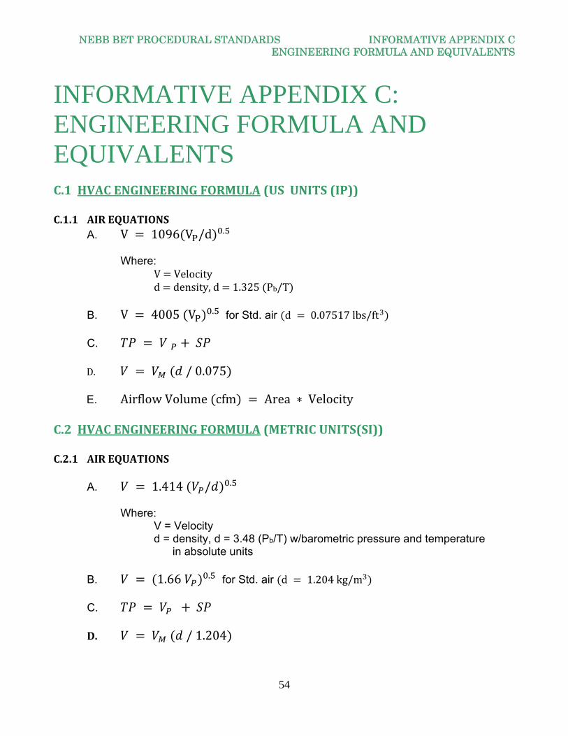
NEBB BET PROCEDURAL STANDARDS INFORMATIVE APPENDIX C ENGINEERING FORMULA AND EQUIVALENTS
54
INFORMATIVE APPENDIX C: ENGINEERING FORMULA AND EQUIVALENTS C.1HVACENGINEERINGFORMULA(USUNITS(IP))C.1.1 AIREQUATIONS A. V 1096 V /d . Where: V Velocity d density,d 1.325 Pb/T B. V 4005 V . for Std. air d 0.07517lbs/ft C.
D. /0.075 E. AirflowVolume cfm Area ∗ Velocity
C.2HVACENGINEERINGFORMULA(METRICUNITS(SI))C.2.1 AIREQUATIONS
A. 1.414 / . Where: V = Velocity d = density, d = 3.48 (Pb/T) w/barometric pressure and temperature
in absolute units
B. 1.66 . for Std. air d 1.204kg/m C. D. /1.204
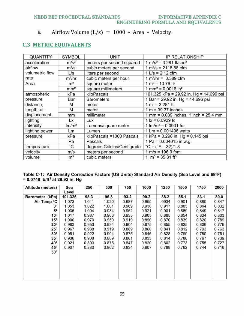
NEBB BET PROCEDURAL STANDARDS INFORMATIVE APPENDIX C ENGINEERING FORMULA AND EQUIVALENTS
55
E. AirflowVolume L/s 1000 ∗ Area ∗ Velocity C.3METRICEQUIVALENTS
Table C-1: Air Density Correction Factors (US Units) Standard Air Density (Sea Level and 68ºF) = 0.0748 lb/ft3 at 29.92 in. Hg
QUANTITY SYMBOL UNIT IP RELATIONSHIP acceleration m/s² meters per second squared 1 m/s² = 3.281 ft/sec² airflow volumetric flow rate
m³/s cubic meters per second 1 m³/s = 2118.88 cfm L/s liters per second 1 L/s = 2.12 cfm
m³/hr cubic meters per hour 1 m³/hr = 0.589 cfm Area m² square meter 1 m² = 10.76 ft²
mm² square millimeters 1 mm² = 0.0016 in² atmospheric pressure
kPa kiloPascals 101.325 kPa = 29.92 in. Hg = 14.696 psiBar Barometers 1 Bar = 29.92 in. Hg = 14.696 psi
distance, length, or displacement
M meter 1 m = 3.281 ft. M meter 1 m = 39.37 inches
mm millimeter 1 mm = 0.039 inches, 1 inch = 25.4 mm lighting intensity
Lx Lux 1 lx = 0.0929 fc lm/m² Lumens/square meter 1 lm/m² = 0.0931 fc
lighting power Lm Lumen 1 Lm = 0.001496 watts pressure kPa kiloPascals =1000 Pascals 1 kPa = 0.296 in. Hg = 0.145 psi
Pa Pascals 1 Pa = 0.004015 in.w.g. temperature °C degrees Celsius/Centigrade °C = (°F – 32)/1.8 velocity m/s meters per second 1 m/s = 196.9 fpm volume m³ cubic meters 1 m³ = 35.31 ft³
Altitude (meters) Sea Level
250 500 750 1000 1250 1500 1750 2000
Barometer (kPa) 101.325 98.3 96.3 93.2 90.2 88.2 85.1 83.1 80.0 Air Temp ºC
0º 5º
10º 15º 20º 25º 30º 35º 40º 45º 50º
1.073 1.053 1.035 1.017 1.000 0.983 0.967 0.951 0.936 0.921 0.907
1.041 1.022 1.004 0.987 0.970 0.953 0.938 0.922 0.908 0.893 0.880
1.020 1.001 0.984 0.966 0.950 0.934 0.919 0.904 0.889 0.875 0.862
0.987 0.969 0.952 0.935 0.919 0.904 0.889 0.875 0.861 0.847 0.834
0.955 0.938 0.921 0.905 0.890 0.875 0.860 0.846 0.833 0.820 0.807
.0934 0.917 0.901 0.885 0.870 0.855 0.841 0.828 0.814 0.802 0.789
0.901 0.885 0.869 0.854 0.839 0.825 0.812 0.799 0.786 0.773 0.762
0.880 0.864 0.849 0.834 0.820 0.806 0.793 0.780 0.767 0.755 0.744
0.8470.8320.8170.8030.7890.7760.7630.7510.7390.7270.716
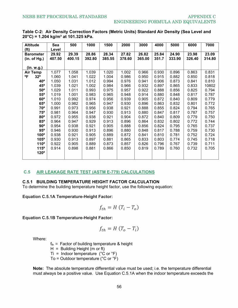
NEBB BET PROCEDURAL STANDARDS APPENDIX C ENGINEERING FORMULA AND EQUIVALENTS
56
Table C-2: Air Density Correction Factors (Metric Units) Standard Air Density (Sea Level and 20°C) = 1.204 kg/m³ at 101.325 kPa.
C.5 AIR LEAKAGE RATE TEST (ASTM E-779) CALCULATIONS C.5.1 BUILDING TEMPERATURE HEIGHT FACTOR CALCULATION To determine the building temperature height factor, use the following equation:
Equation C.5.1A Temperature-Height Factor:
Equation C.5.1B Temperature-Height Factor:
Where:
fth = Factor of building temperature & height H = Building Height (m or ft) Ti = Indoor temperature (°C or °F) To = Outdoor temperature (°C or °F)
Note: The absolute temperature differential value must be used; i.e. the temperature differential must always be a positive value. Use Equation C.5.1A when the indoor temperature exceeds the
Altitude (ft)
Sea Level
500 1000 1500 2000 3000 4000 5000 6000 7000
Barometer (in. of Hg.)
(in. w.g.)
29.92 407.50
29.39 400.15
28.86 392.80
28.34 385.55
27.82 378.60
26.82 365.00
25.84351.7
24.90 333.90
23.98 326.40
23.09 314.80
Air Temp ºF 32º
40º 45º 50º 55º 60º 65º 70º 75º 80º 85º 90º 95º
100º 105º 110º 115º 120º
1.077 1.060 1.050 1.039 1.029 1.019 1.010 1.000 0.991 0.981 0.972 0.964 0.954 0.946 0.938 0.930 0.922 0.914
1.058 1.041 1.031 1.021 1.011 1.001 0.992 0.982 0.973 0.964 0.955 0.947 0.938 0.930 0.921 0.913 0.905 0.898
1.039 1.022 1.012 1.002 0.993 0.983 0.974 0.965 0.956 0.947 0.938 0.929 0.921 0.913 0.905 0.897 0.889 0.881
1.020 1.004 0.994 0.984 0.975 0.965 0.956 0.947 0.938 0.930 0.921 0.913 0.905 0.896 0.889 0.881 0.873 0.866
1.002 0.986 0.976 0.966 0.957 0.948 0.939 0.930 0.921 0.913 0.904 0.896 0.888 0.880 0.872 0.865 0.857 0.850
0.966 0.950 0.941 0.932 0.922 0.914 0.905 0.896 0.888 0.880 0.872 0.864 0.856 0.848 0.841 0.833 0.826 0.819
0.9300.9150.9060.8970.8880.8800.8720.8630.8550.8470.8400.8320.8240.8170.8100.8030.7960.789
0.896 0.882 0.873 0.865 0.856 0.848 0.840 0.832 0.824 0.817 0.809 0.802 0.795 0.788 0.781 0.774 0.767 0.760
0.863 0.850 0.841 0.833 0.825 0.817 0.809 0.801 0.794 0.787 0.779 0.772 0.765 0.759 0.752 0.745 0.739 0.732
0.831 0.818 0.810 10802 0.794 0.787 0.779 0.772 0.765 0.757 0.750 0.744 0.737 0.730 0.724 0.718 0.711 0.705
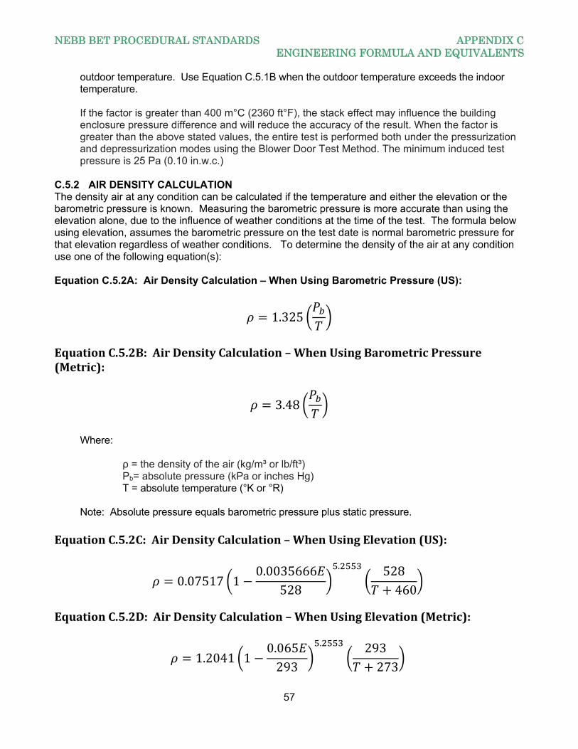
NEBB BET PROCEDURAL STANDARDS APPENDIX C ENGINEERING FORMULA AND EQUIVALENTS
57
outdoor temperature. Use Equation C.5.1B when the outdoor temperature exceeds the indoor temperature. If the factor is greater than 400 m°C (2360 ft°F), the stack effect may influence the building enclosure pressure difference and will reduce the accuracy of the result. When the factor is greater than the above stated values, the entire test is performed both under the pressurization and depressurization modes using the Blower Door Test Method. The minimum induced test pressure is 25 Pa (0.10 in.w.c.)
C.5.2 AIR DENSITY CALCULATION The density air at any condition can be calculated if the temperature and either the elevation or the barometric pressure is known. Measuring the barometric pressure is more accurate than using the elevation alone, due to the influence of weather conditions at the time of the test. The formula below using elevation, assumes the barometric pressure on the test date is normal barometric pressure for that elevation regardless of weather conditions. To determine the density of the air at any condition use one of the following equation(s): Equation C.5.2A: Air Density Calculation – When Using Barometric Pressure (US):
1.325
EquationC.5.2B:AirDensityCalculation–WhenUsingBarometricPressure(Metric):
3.48
Where:
ρ = the density of the air (kg/m³ or lb/ft³) Pb= absolute pressure (kPa or inches Hg)
T = absolute temperature (°K or °R) Note: Absolute pressure equals barometric pressure plus static pressure. EquationC.5.2C:AirDensityCalculation–WhenUsingElevation(US):
0.07517 10.0035666
528
. 528460
EquationC.5.2D:AirDensityCalculation–WhenUsingElevation(Metric):
1.2041 10.065293
. 293273
NEBB BET PROCEDURAL STANDARDS APPENDIX C ENGINEERING FORMULA AND EQUIVALENTS
58
Where:
ρ = the density of the air (kg/m³ or lb/ft³) E = elevation above sea level (m or ft)
T = measured temperature (°C or °F) – inside temperature when calculating the inside density; outside temperature when calculating the outside density
When calculating air density, it is necessary to calculate the density of the indoor air, the outdoor air and the density at standard conditions, which is sea level and 20°C (68°F). The density of standard air can be calculated using any of Equations above. To calculate the density of the indoor air, you would use any of the above equations and insert the temperature of the indoor air. Likewise, to calculate the outdoor air density, you would use the temperature of the outdoor air. C.5.3 CONVERTINGAIRFLOWRATESFORPRESSURIZATIONANDDEPRESSURIZATIONTo convert the measured airflow rate to air leakage rate for depressurization, use the following equation: Equation C.5.3A (De-Pressurization):
Where:
Q = the measured airflow (m³/sec or ft³/min) Qo = the outdoor airflow (m³/sec or ft³/min) ρin = the density of the indoor air (kg/m³ or lb/ft³) ρout = the density of the outdoor air (kg/m³ or lb/ft³) To convert the measured airflow rate to air leakage rate for pressurization, use the following equation: Equation C.5.3B (Pressurization):
Where: Q = the measured airflow (m³/sec or ft³/min) Qo = the outdoor airflow (m³/sec or ft³/min) ρin = the density of the indoor air (kg/m³ or lb/ft³) ρout = the density of the outdoor air (kg/m³ or lb/ft³) C.5.4 DYNAMICVISCOSITYOFAIRCALCULATIONThedynamicviscosityofairatanytemperaturecanbecalculatedusingthefollowingequation:EquationC.5.4A:DynamicViscosityCalculation(US)
NEBB BET PROCEDURAL STANDARDS APPENDIX C ENGINEERING FORMULA AND EQUIVALENTS
59
460 .
1
Where: = dynamic viscosity (lb/ft-hr)
b = 2.629 ∗ 10-3 (lb/( ft·h·°R0.5) S=198.7(°R) T=Temperatureoftheair(°F) EquationC.5.4B:DynamicViscosityCalculation(Metric)
273 .
1
Where:
= dynamic viscosity (kg/m-s) b = 1.458 ∗ 10-6 (kg/(m·s·°K0.5)
S = 110.4 (°K) T = Temperature of the air (°C) C.5.5 AIRLEAKAGECOEFFICIENTANDPRESSUREEXPONENTTo determine the air leakage coefficient and the pressure exponent, use the following equation: Equation C.5.5
Where:
Q = air leakage flow rate (cfm or m³/s) C = air leakage coefficient (CFM/ in.w.c.)
P = differential pressure (Pa or in.w.c.) n = pressure exponent (dimensionless)
C.5.6 AIRLEAKAGECOEFFICIENTCORRECTIONCALCULATIONCorrect the air leakage coefficient C to standard conditions using the following equation: Equation C.5.6:
Where: C = leakage coefficient (CFM/ in.w.c.) = the dynamic viscosity (lb/ft-hr or kg/m-s) 0 = the dynamic viscosity (lb/ft-hr or kg/m-s)
NEBB BET PROCEDURAL STANDARDS APPENDIX C ENGINEERING FORMULA AND EQUIVALENTS
60
ρ = the air density (lb/ft³ or kg/m³) ρo = the air density (lb/ft³ or kg/m³) n = pressure exponent
Note: Dynamic viscosity can be calculated using Equation C.5.4.
C.5.7 LEAKAGEAREACALCULATIONThe leakage area can be calculated from the corrected air leakage coefficient and the pressure exponent using the following equation: Equation C.5.7:
0.1855.∆ . (US)
.∆ . (Metric)
Where: AL = the leakage area (m² or ft²) C0 = corrected leakage coefficient (CFM/ in.w.c.)
ρo = the outdoor (depressurization) or the indoor (pressurization) air density, kg/m³(lb/ft³)
n = pressure exponent Pr = the reference pressure (Pa or in.w.c.) C.5.8 PROCEDUREFORESTIMATINGERRORSINDERIVEDQUANTITIESThis test method contains several derived quantities, which often are used to summarize the air tightness of the building or component tested. It is important to report an estimate of the error in such quantities. The following method is recommended: all derived quantities depend on the estimation of the air leakage coefficient C and air pressure exponent n of Eq. C.5.5. To determine C and n, make a log transformation of the variables Q and P for each reading.
xi ln dPi andyi ln Qi fori 1..N
Where:
N = the total number of test readings. Equation C.5.5 then becomes the following equation: Equation C.5.8A:
ln Then, compute the Average of the Log of Pressure, the Average of the Log of Airflow, the Variance of the Log of Pressure, the Variance of the Log of Flow and the Co-Variance of the Log of pressure and Airflow using the following equations below:
NEBB BET PROCEDURAL STANDARDS APPENDIX C ENGINEERING FORMULA AND EQUIVALENTS
61
Equation C.5.8B: Average of the Log of the Differential Pressures P:
1
Where:
= the average log of pressure = the individual log of pressure at each test reading N = the number of readings
Equation C.5.8C: Average of the Log of the Airflow
1
Where: = the average log of airflow = the individual log of airflow at each test reading N = the number of readings
Equation C.5.8D: Variance of the Log of Pressure:
11
Note: To find Sx use the following formula
.
Equation C.5.8E: Variance of the Log of Airflow
11
Equation C.5F Co-Variance of the Log of Pressure and Airflow
11 ∗
Where: = the average log of pressure
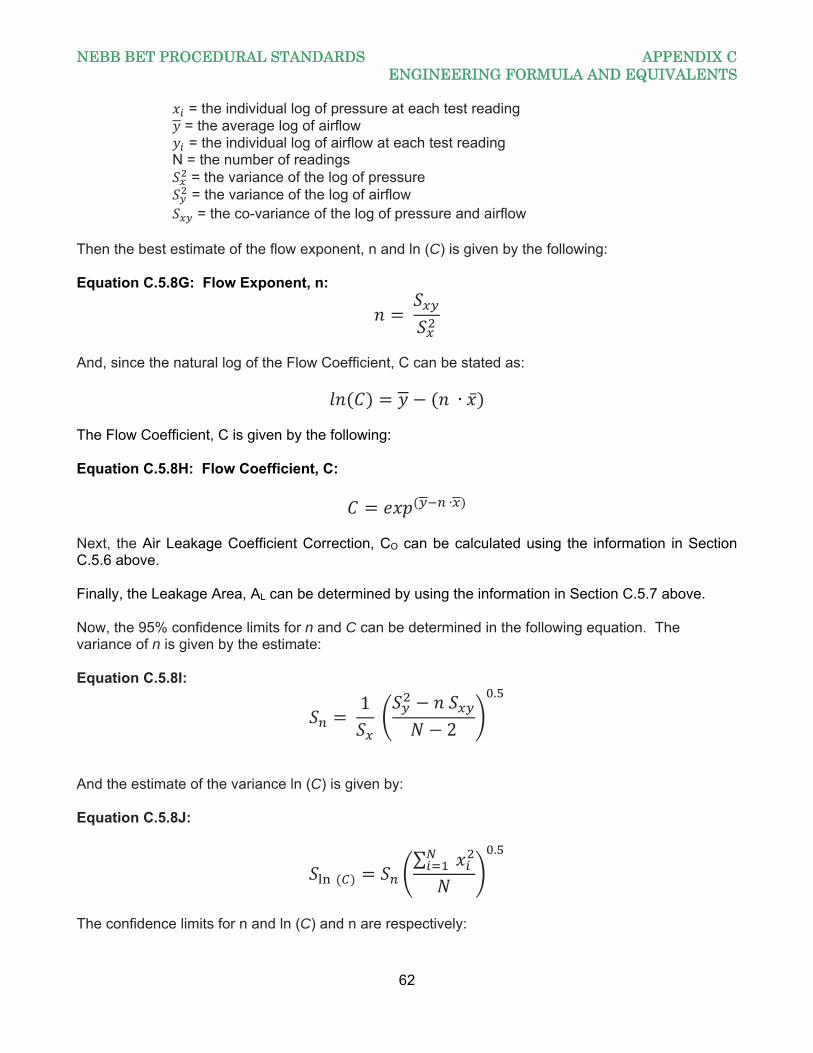
NEBB BET PROCEDURAL STANDARDS APPENDIX C ENGINEERING FORMULA AND EQUIVALENTS
62
= the individual log of pressure at each test reading = the average log of airflow = the individual log of airflow at each test reading N = the number of readings = the variance of the log of pressure = the variance of the log of airflow = the co-variance of the log of pressure and airflow Then the best estimate of the flow exponent, n and ln (C) is given by the following: Equation C.5.8G: Flow Exponent, n:
And, since the natural log of the Flow Coefficient, C can be stated as:
∙ ̅ The Flow Coefficient, C is given by the following: Equation C.5.8H: Flow Coefficient, C:
∙ Next, the Air Leakage Coefficient Correction, CO can be calculated using the information in Section C.5.6 above. Finally, the Leakage Area, AL can be determined by using the information in Section C.5.7 above. Now, the 95% confidence limits for n and C can be determined in the following equation. The variance of n is given by the estimate: Equation C.5.8I:
1
2
.
And the estimate of the variance ln (C) is given by: Equation C.5.8J:
∑
.
The confidence limits for n and ln (C) and n are respectively:
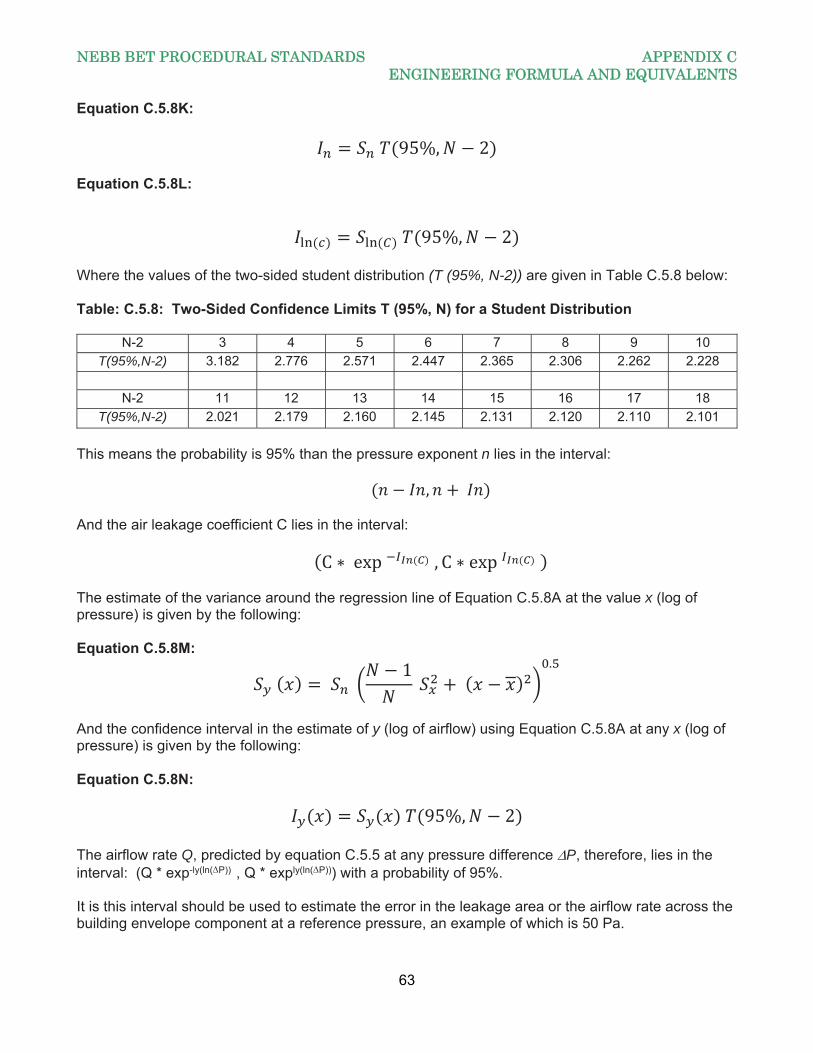
NEBB BET PROCEDURAL STANDARDS APPENDIX C ENGINEERING FORMULA AND EQUIVALENTS
63
Equation C.5.8K:
95%, 2 Equation C.5.8L:
95%, 2 Where the values of the two-sided student distribution (T (95%, N-2)) are given in Table C.5.8 below: Table: C.5.8: Two-Sided Confidence Limits T (95%, N) for a Student Distribution
N-2 3 4 5 6 7 8 9 10
T(95%,N-2) 3.182 2.776 2.571 2.447 2.365 2.306 2.262 2.228
N-2 11 12 13 14 15 16 17 18
T(95%,N-2) 2.021 2.179 2.160 2.145 2.131 2.120 2.110 2.101
This means the probability is 95% than the pressure exponent n lies in the interval:
, And the air leakage coefficient C lies in the interval:
C ∗ exp , C∗ exp The estimate of the variance around the regression line of Equation C.5.8A at the value x (log of pressure) is given by the following: Equation C.5.8M:
1
.
And the confidence interval in the estimate of y (log of airflow) using Equation C.5.8A at any x (log of pressure) is given by the following: Equation C.5.8N:
95%, 2 The airflow rate Q, predicted by equation C.5.5 at any pressure difference P, therefore, lies in the interval: (Q * exp-ly(ln(P))
, Q * exply(ln(P))) with a probability of 95%. It is this interval should be used to estimate the error in the leakage area or the airflow rate across the building envelope component at a reference pressure, an example of which is 50 Pa.
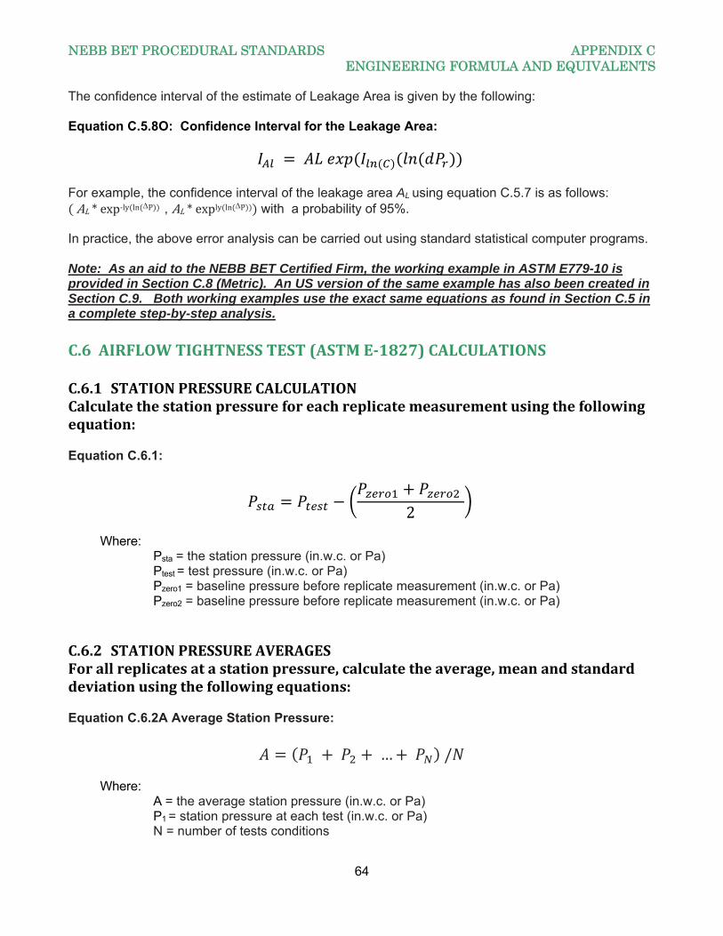
NEBB BET PROCEDURAL STANDARDS APPENDIX C ENGINEERING FORMULA AND EQUIVALENTS
64
The confidence interval of the estimate of Leakage Area is given by the following: Equation C.5.8O: Confidence Interval for the Leakage Area:
For example, the confidence interval of the leakage area AL using equation C.5.7 is as follows: AL*exp‐ly ln P
, AL*exply ln P with a probability of 95%. In practice, the above error analysis can be carried out using standard statistical computer programs. Note: As an aid to the NEBB BET Certified Firm, the working example in ASTM E779-10 is provided in Section C.8 (Metric). An US version of the same example has also been created in Section C.9. Both working examples use the exact same equations as found in Section C.5 in a complete step-by-step analysis.
C.6AIRFLOWTIGHTNESSTEST(ASTME‐1827)CALCULATIONSC.6.1 STATIONPRESSURECALCULATIONCalculatethestationpressureforeachreplicatemeasurementusingthefollowingequation: Equation C.6.1:
2
Where: Psta = the station pressure (in.w.c. or Pa) Ptest = test pressure (in.w.c. or Pa) Pzero1 = baseline pressure before replicate measurement (in.w.c. or Pa) Pzero2 = baseline pressure before replicate measurement (in.w.c. or Pa)
C.6.2 STATIONPRESSUREAVERAGESForallreplicatesatastationpressure,calculatetheaverage,meanandstandarddeviationusingthefollowingequations: Equation C.6.2A Average Station Pressure:
… /
Where: A = the average station pressure (in.w.c. or Pa) P1 = station pressure at each test (in.w.c. or Pa) N = number of tests conditions
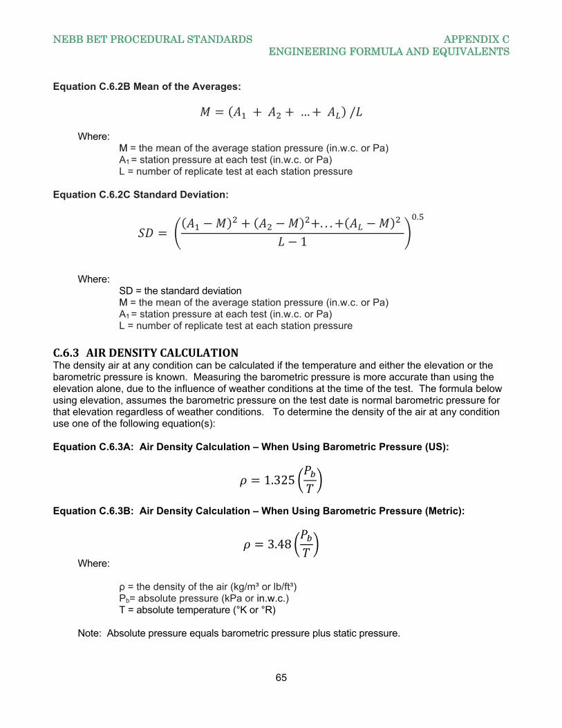
NEBB BET PROCEDURAL STANDARDS APPENDIX C ENGINEERING FORMULA AND EQUIVALENTS
65
Equation C.6.2B Mean of the Averages:
… / Where: M = the mean of the average station pressure (in.w.c. or Pa) A1 = station pressure at each test (in.w.c. or Pa) L = number of replicate test at each station pressure Equation C.6.2C Standard Deviation:
. . .
1
.
Where: SD = the standard deviation M = the mean of the average station pressure (in.w.c. or Pa) A1 = station pressure at each test (in.w.c. or Pa) L = number of replicate test at each station pressure C.6.3 AIRDENSITYCALCULATIONThe density air at any condition can be calculated if the temperature and either the elevation or the barometric pressure is known. Measuring the barometric pressure is more accurate than using the elevation alone, due to the influence of weather conditions at the time of the test. The formula below using elevation, assumes the barometric pressure on the test date is normal barometric pressure for that elevation regardless of weather conditions. To determine the density of the air at any condition use one of the following equation(s): Equation C.6.3A: Air Density Calculation – When Using Barometric Pressure (US):
1.325
Equation C.6.3B: Air Density Calculation – When Using Barometric Pressure (Metric):
3.48 Where:
ρ = the density of the air (kg/m³ or lb/ft³) Pb= absolute pressure (kPa or in.w.c.)
T = absolute temperature (°K or °R) Note: Absolute pressure equals barometric pressure plus static pressure.
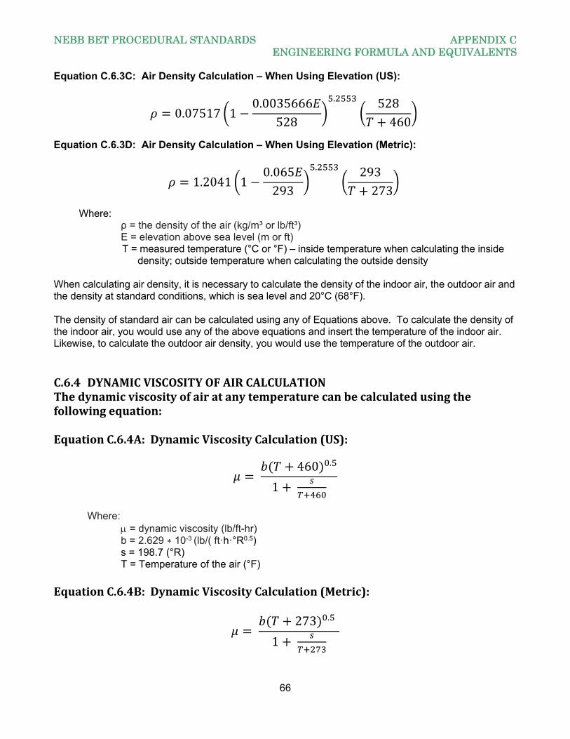
NEBB BET PROCEDURAL STANDARDS APPENDIX C ENGINEERING FORMULA AND EQUIVALENTS
66
Equation C.6.3C: Air Density Calculation – When Using Elevation (US):
0.07517 10.0035666
528
. 528460
Equation C.6.3D: Air Density Calculation – When Using Elevation (Metric):
1.2041 10.065293
. 293273
Where:
ρ = the density of the air (kg/m³ or lb/ft³) E = elevation above sea level (m or ft)
T = measured temperature (°C or °F) – inside temperature when calculating the inside density; outside temperature when calculating the outside density
When calculating air density, it is necessary to calculate the density of the indoor air, the outdoor air and the density at standard conditions, which is sea level and 20°C (68°F). The density of standard air can be calculated using any of Equations above. To calculate the density of the indoor air, you would use any of the above equations and insert the temperature of the indoor air. Likewise, to calculate the outdoor air density, you would use the temperature of the outdoor air. C.6.4 DYNAMICVISCOSITYOFAIRCALCULATIONThedynamicviscosityofairatanytemperaturecanbecalculatedusingthefollowingequation:EquationC.6.4A:DynamicViscosityCalculation(US):
460 .
1
Where: = dynamic viscosity (lb/ft-hr)
b = 2.629 ∗ 10-3 (lb/( ft·h·°R0.5) s = 198.7 (°R) T = Temperature of the air (°F) EquationC.6.4B:DynamicViscosityCalculation(Metric):
273 .
1
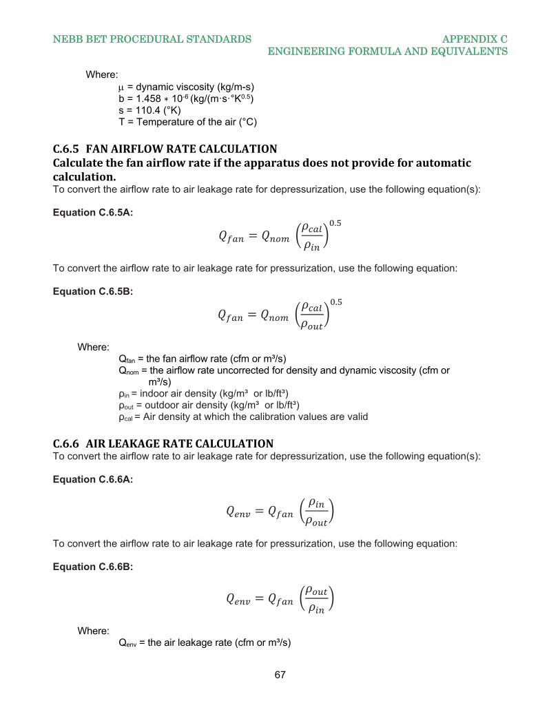
NEBB BET PROCEDURAL STANDARDS APPENDIX C ENGINEERING FORMULA AND EQUIVALENTS
67
Where: = dynamic viscosity (kg/m-s) b = 1.458 ∗ 10-6 (kg/(m·s·°K0.5)
s = 110.4 (°K) T = Temperature of the air (°C) C.6.5 FANAIRFLOWRATECALCULATIONCalculatethefanairflowrateiftheapparatusdoesnotprovideforautomaticcalculation.To convert the airflow rate to air leakage rate for depressurization, use the following equation(s): Equation C.6.5A:
.
To convert the airflow rate to air leakage rate for pressurization, use the following equation: Equation C.6.5B:
.
Where: Qfan = the fan airflow rate (cfm or m³/s) Qnom = the airflow rate uncorrected for density and dynamic viscosity (cfm or
m³/s) ρin = indoor air density (kg/m³ or lb/ft³) ρout = outdoor air density (kg/m³ or lb/ft³)
ρcal = Air density at which the calibration values are valid C.6.6 AIRLEAKAGERATECALCULATIONTo convert the airflow rate to air leakage rate for depressurization, use the following equation(s): Equation C.6.6A:
To convert the airflow rate to air leakage rate for pressurization, use the following equation: Equation C.6.6B:
Where: Qenv = the air leakage rate (cfm or m³/s)
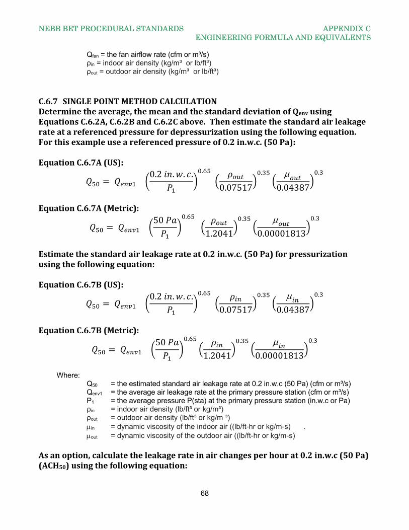
NEBB BET PROCEDURAL STANDARDS APPENDIX C ENGINEERING FORMULA AND EQUIVALENTS
68
Qfan = the fan airflow rate (cfm or m³/s) ρin = indoor air density (kg/m³ or lb/ft³) ρout = outdoor air density (kg/m³ or lb/ft³) C.6.7 SINGLEPOINTMETHODCALCULATIONDeterminetheaverage,themeanandthestandarddeviationofQenvusingEquationsC.6.2A,C.6.2BandC.6.2Cabove.Thenestimatethestandardairleakagerateatareferencedpressurefordepressurizationusingthefollowingequation.Forthisexampleuseareferencedpressureof0.2in.w.c.(50Pa):EquationC.6.7A(US):
0.2 . . . .
0.07517
. 0.04387
.
EquationC.6.7A(Metric):
50 .
1.2041
. 0.00001813
.
Estimatethestandardairleakagerateat0.2in.w.c.(50Pa)forpressurizationusingthefollowingequation:EquationC.6.7B(US):
0.2 . . . .
0.07517
. 0.04387
.
EquationC.6.7B(Metric):
50 .
1.2041
. 0.00001813
.
Where: Q50 = the estimated standard air leakage rate at 0.2 in.w.c (50 Pa) (cfm or m³/s) Qenv1 = the average air leakage rate at the primary pressure station (cfm or m³/s) P1 = the average pressure P(sta) at the primary pressure station (in.w.c or Pa) ρin = indoor air density (lb/ft³ or kg/m³) ρout = outdoor air density (lb/ft³ or kg/m ³) in = dynamic viscosity of the indoor air ((lb/ft-hr or kg/m-s) . out = dynamic viscosity of the outdoor air ((lb/ft-hr or kg/m-s) Asanoption,calculatetheleakagerateinairchangesperhourat0.2in.w.c(50Pa)(ACH50)usingthefollowingequation:
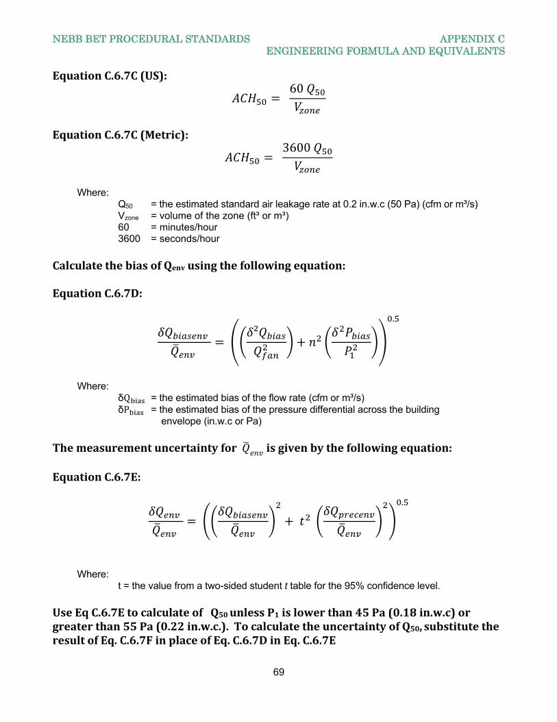
NEBB BET PROCEDURAL STANDARDS APPENDIX C ENGINEERING FORMULA AND EQUIVALENTS
69
EquationC.6.7C(US):
60
EquationC.6.7C(Metric):
3600
Where: Q50 = the estimated standard air leakage rate at 0.2 in.w.c (50 Pa) (cfm or m³/s) Vzone = volume of the zone (ft³ or m³) 60 = minutes/hour 3600 = seconds/hour CalculatethebiasofQenvusingthefollowingequation:EquationC.6.7D:
².
Where: δQ = the estimated bias of the flow rate (cfm or m³/s) δP = the estimated bias of the pressure differential across the building
envelope (in.w.c or Pa) Themeasurementuncertaintyfor isgivenbythefollowingequation:EquationC.6.7E:
.
Where: t = the value from a two-sided student t table for the 95% confidence level. UseEqC.6.7EtocalculateofQ50unlessP1islowerthan45Pa(0.18in.w.c)orgreaterthan55Pa(0.22in.w.c.).TocalculatetheuncertaintyofQ50,substitutetheresultofEq.C.6.7FinplaceofEq.C.6.7DinEq.C.6.7E
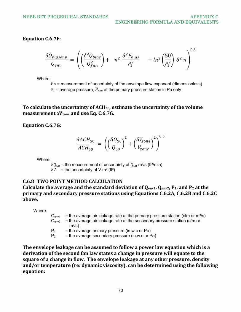
NEBB BET PROCEDURAL STANDARDS APPENDIX C ENGINEERING FORMULA AND EQUIVALENTS
70
EquationC.6.7F:
²
50
.
Where: δn = measurement of uncertainty of the envelope flow exponent (dimensionless) P = average pressure, at the primary pressure station in Pa only TocalculatetheuncertaintyofACH50,estimatetheuncertaintyofthevolumemeasurementδVzoneanduseEq.C.6.7G.EquationC.6.7G:
.
Where: δ = the measurement of uncertainty of m³/s (ft³/min) δ = the uncertainty of V m³ (ft³) C.6.8 TWOPOINTMETHODCALCULATIONCalculatetheaverageandthestandarddeviationofQenv1,Qenv2,P1,andP2attheprimaryandsecondarypressurestationsusingEquationsC.6.2A,C.6.2BandC.6.2Cabove. Where: Qenv1 = the average air leakage rate at the primary pressure station (cfm or m³/s) Qenv2 = the average air leakage rate at the secondary pressure station (cfm or m³/s) P1 = the average primary pressure (in.w.c or Pa) P2 = the average secondary pressure (in.w.c or Pa) Theenvelopeleakagecanbeassumedtofollowapowerlawequationwhichisaderivationofthesecondfanlawstatesachangeinpressurewillequatetothesquareofachangeinflow.Theenvelopeleakageatanyotherpressure,densityand/ortemperature(re:dynamicviscosity),canbedeterminedusingthefollowingequation:
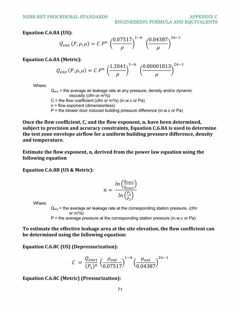
NEBB BET PROCEDURAL STANDARDS APPENDIX C ENGINEERING FORMULA AND EQUIVALENTS
71
EquationC.6.8A(US):
, , 0.07517
0.04387
EquationC.6.8A(Metric):
, , 1.2041
0.00001813
Where: Qenv = the average air leakage rate at any pressure, density and/or dynamic viscosity (cfm or m³/s) C = the flow coefficient (cfm or m³/s) (in.w.c or Pa) n = flow exponent (dimensionless) P = the blower door induced building pressure difference (in.w.c or Pa) Oncetheflowcoefficient,C,andtheflowexponent,n,havebeendetermined,subjecttoprecisionandaccuracyconstraints,EquationC.6.8Aisusedtodeterminethetestzoneenvelopeairflowforauniformbuildingpressuredifference,densityandtemperature.Estimatetheflowexponent,n,derivedfromthepowerlawequationusingthefollowingequationEquationC.6.8B(US&Metric):
Where: Qenv = the average air leakage rate at the corresponding station pressure, (cfm or m³/s) P = the average pressure at the corresponding station pressure (in.w.c or Pa) Toestimatetheeffectiveleakageareaatthesiteelevation,theflowcoefficientcanbedeterminedusingthefollowingequation:EquationC.6.8C(US)(Depressurization):
0.07517 0.04387
EquationC.6.8C(Metric)(Pressurization):
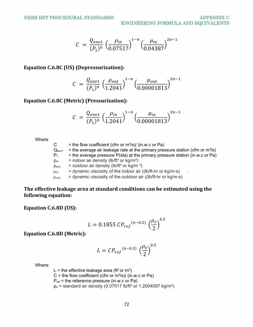
NEBB BET PROCEDURAL STANDARDS APPENDIX C ENGINEERING FORMULA AND EQUIVALENTS
72
0.07517 0.04387
EquationC.6.8C(US)(Depressurization):
1.2041 0.00001813
EquationC.6.8C(Metric)(Pressurization):
1.2041 0.00001813
Where C = the flow coefficient (cfm or m³/s)/ (in.w.c or Pa) Qenv1 = the average air leakage rate at the primary pressure station (cfm or m³/s) P1 = the average pressure P(sta) at the primary pressure station (in.w.c or Pa) ρin = indoor air density (lb/ft³ or kg/m³) ρout = outdoor air density (lb/ft³ or kg/m ³) in = dynamic viscosity of the indoor air ((lb/ft-hr or kg/m-s) . out = dynamic viscosity of the outdoor air ((lb/ft-hr or kg/m-s)Theeffectiveleakageareaatstandardconditionscanbeestimatedusingthefollowingequation:EquationC.6.8D(US):
0.1855 . 2
.
EquationC.6.8D(Metric):
. 2
.
Where: L = the effective leakage area (ft2 or m2) C = the flow coefficient (cfm or m³/s)/ (in.w.c or Pa) Pref = the reference pressure (in.w.c or Pa) ρe = standard air density (0.07517 lb/ft³ or 1.2004097 kg/m³)
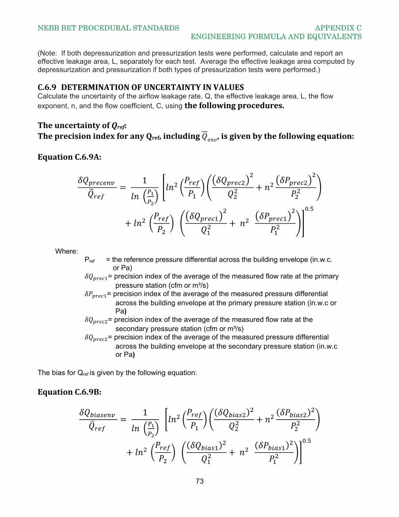
NEBB BET PROCEDURAL STANDARDS APPENDIX C ENGINEERING FORMULA AND EQUIVALENTS
73
(Note: If both depressurization and pressurization tests were performed, calculate and report an effective leakage area, L, separately for each test. Average the effective leakage area computed by depressurization and pressurization if both types of pressurization tests were performed.) C.6.9 DETERMINATIONOFUNCERTAINTYINVALUESCalculate the uncertainty of the airflow leakage rate, Q, the effective leakage area, L, the flow exponent, n, and the flow coefficient, C, using thefollowingprocedures.TheuncertaintyofQref:TheprecisionindexforanyQref,including ,isgivenbythefollowingequation:EquationC.6.9A:
1
.
Where: Pref = the reference pressure differential across the building envelope (in.w.c. or Pa) = precision index of the average of the measured flow rate at the primary pressure station (cfm or m³/s) = precision index of the average of the measured pressure differential across the building envelope at the primary pressure station (in.w.c or Pa) = precision index of the average of the measured flow rate at the secondary pressure station (cfm or m³/s) = precision index of the average of the measured pressure differential across the building envelope at the secondary pressure station (in.w.c or Pa) The bias for Qref is given by the following equation: EquationC.6.9B:
1
.
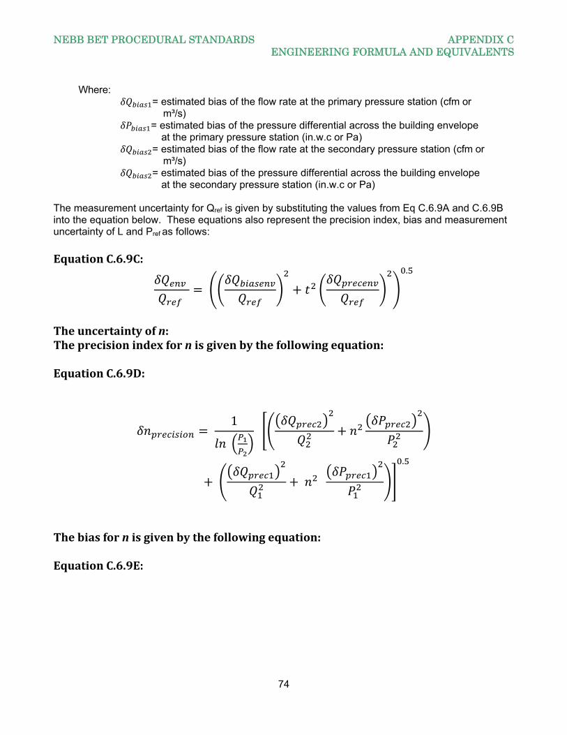
NEBB BET PROCEDURAL STANDARDS APPENDIX C ENGINEERING FORMULA AND EQUIVALENTS
74
Where: = estimated bias of the flow rate at the primary pressure station (cfm or m³/s) = estimated bias of the pressure differential across the building envelope at the primary pressure station (in.w.c or Pa) = estimated bias of the flow rate at the secondary pressure station (cfm or m³/s) = estimated bias of the pressure differential across the building envelope at the secondary pressure station (in.w.c or Pa) The measurement uncertainty for Qref is given by substituting the values from Eq C.6.9A and C.6.9B into the equation below. These equations also represent the precision index, bias and measurement uncertainty of L and Pref as follows: EquationC.6.9C:
.
Theuncertaintyofn:Theprecisionindexfornisgivenbythefollowingequation:EquationC.6.9D:
1
.
Thebiasfornisgivenbythefollowingequation:EquationC.6.9E:
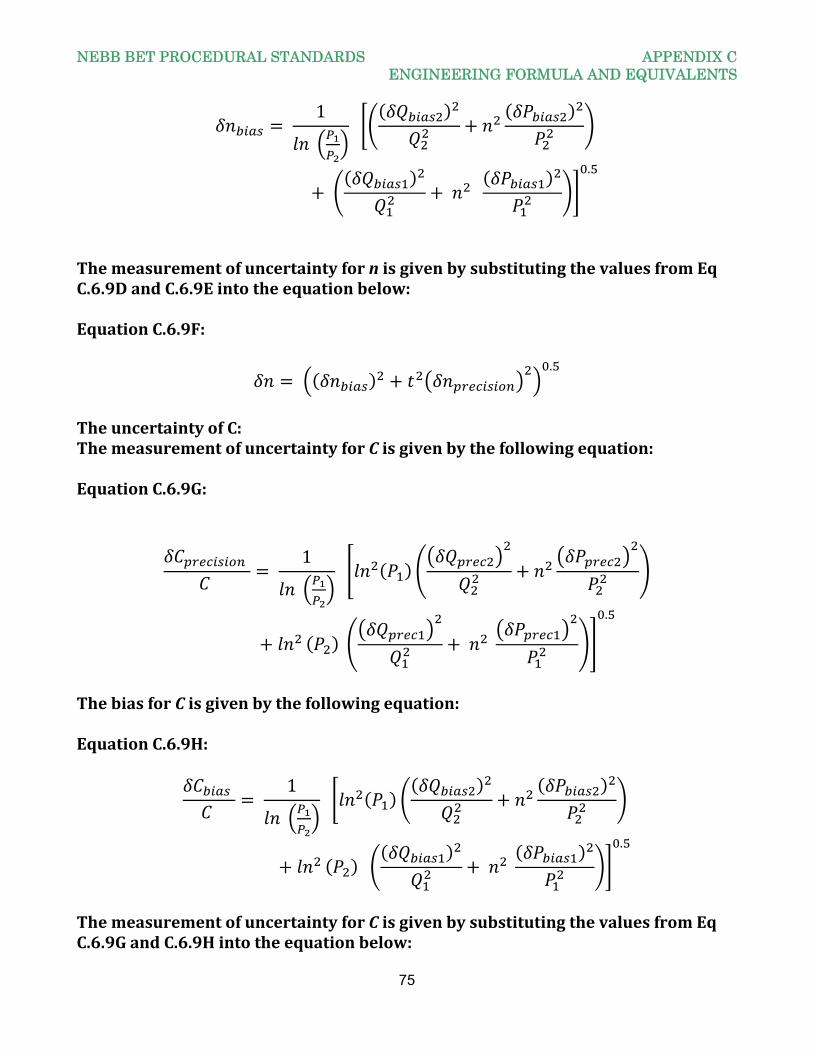
NEBB BET PROCEDURAL STANDARDS APPENDIX C ENGINEERING FORMULA AND EQUIVALENTS
75
1
.
ThemeasurementofuncertaintyfornisgivenbysubstitutingthevaluesfromEqC.6.9DandC.6.9Eintotheequationbelow:EquationC.6.9F:
.
TheuncertaintyofC:ThemeasurementofuncertaintyforCisgivenbythefollowingequation:EquationC.6.9G:
1
.
ThebiasforCisgivenbythefollowingequation:EquationC.6.9H:
1
.
ThemeasurementofuncertaintyforCisgivenbysubstitutingthevaluesfromEqC.6.9GandC.6.9Hintotheequationbelow:
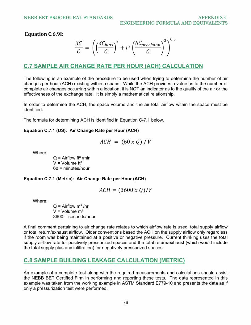
NEBB BET PROCEDURAL STANDARDS APPENDIX C ENGINEERING FORMULA AND EQUIVALENTS
76
EquationC.6.9I:
.
C.7 SAMPLE AIR CHANGE RATE PER HOUR (ACH) CALCULATION The following is an example of the procedure to be used when trying to determine the number of air changes per hour (ACH) existing within a space. While the ACH provides a value as to the number of complete air changes occurring within a location, it is NOT an indicator as to the quality of the air or the effectiveness of the exchange rate. It is simply a mathematical relationship. In order to determine the ACH, the space volume and the air total airflow within the space must be identified. The formula for determining ACH is identified in Equation C-7.1 below. Equation C.7.1 (US): Air Change Rate per Hour (ACH)
60 / Where: Q = Airflow ft³ /min V = Volume ft³ 60 = minutes/hour Equation C.7.1 (Metric): Air Change Rate per Hour (ACH)
3600 / Where: Q = Airflow m³ /hr V = Volume m³ 3600 = seconds/hour A final comment pertaining to air change rate relates to which airflow rate is used; total supply airflow or total return/exhaust airflow. Older conventions based the ACH on the supply airflow only regardless if the room was being maintained at a positive or negative pressure. Current thinking uses the total supply airflow rate for positively pressurized spaces and the total return/exhaust (which would include the total supply plus any infiltration) for negatively pressurized spaces.
C.8 SAMPLE BUILDING LEAKAGE CALCULATION (METRIC) An example of a complete test along with the required measurements and calculations should assist the NEBB BET Certified Firm in performing and reporting these tests. The data represented in this example was taken from the working example in ASTM Standard E779-10 and presents the data as if only a pressurization test were performed.
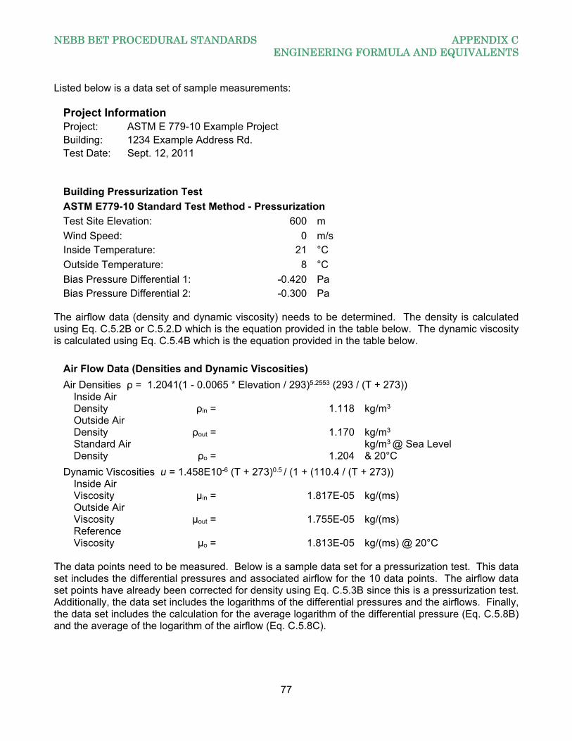
NEBB BET PROCEDURAL STANDARDS APPENDIX C ENGINEERING FORMULA AND EQUIVALENTS
77
Listed below is a data set of sample measurements:
Project Information Project: ASTM E 779-10 Example Project Building: 1234 Example Address Rd. Test Date: Sept. 12, 2011
Building Pressurization Test
ASTM E779-10 Standard Test Method - Pressurization
Test Site Elevation: 600 m
Wind Speed: 0 m/s Inside Temperature: 21 °C
Outside Temperature: 8 °C
Bias Pressure Differential 1: -0.420 Pa Bias Pressure Differential 2: -0.300 Pa
The airflow data (density and dynamic viscosity) needs to be determined. The density is calculated using Eq. C.5.2B or C.5.2.D which is the equation provided in the table below. The dynamic viscosity is calculated using Eq. C.5.4B which is the equation provided in the table below.
Air Flow Data (Densities and Dynamic Viscosities)
Air Densities ρ = 1.2041(1 - 0.0065 * Elevation / 293)5.2553 (293 / (T + 273))
Inside Air Density ρin = 1.118 kg/m3
Outside Air Density ρout = 1.170 kg/m3
Standard Air Density ρo = 1.204
kg/m3 @ Sea Level & 20°C
Dynamic Viscosities u = 1.458E10-6 (T + 273)0.5 / (1 + (110.4 / (T + 273))
Inside Air Viscosity μin = 1.817E-05 kg/(ms)
Outside Air Viscosity μout = 1.755E-05 kg/(ms)
Reference Viscosity μo = 1.813E-05 kg/(ms) @ 20°C
The data points need to be measured. Below is a sample data set for a pressurization test. This data set includes the differential pressures and associated airflow for the 10 data points. The airflow data set points have already been corrected for density using Eq. C.5.3B since this is a pressurization test. Additionally, the data set includes the logarithms of the differential pressures and the airflows. Finally, the data set includes the calculation for the average logarithm of the differential pressure (Eq. C.5.8B) and the average of the logarithm of the airflow (Eq. C.5.8C).
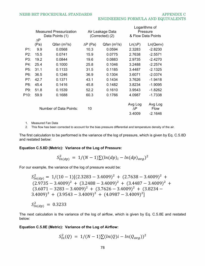
NEBB BET PROCEDURAL STANDARDS APPENDIX C ENGINEERING FORMULA AND EQUIVALENTS
78
Measured Pressurization
Data Points (1) Air Leakage Data
(Corrected) (2)
Logarithms of Pressure
& Flow Data Points
∆P
(Pa) Qfan (m3/s) ∆P (Pa) Qfan (m3/s) Ln(∆P) Ln(Qenv) P1: 9.9 0.0568 10.3 0.0594 2.3283 -2.8230 P2: 15.5 0.0741 15.9 0.0775 2.7638 -2.5571 P3: 19.2 0.0844 19.6 0.0883 2.9735 -2.4270 P4: 25.4 0.1000 25.8 0.1046 3.2488 -2.2574 P5: 31.1 0.1133 31.5 0.1185 3.4487 -2.1325 P6: 36.5 0.1246 36.9 0.1304 3.6071 -2.0374 P7: 42.7 0.1371 43.1 0.1434 3.7626 -1.9418 P8: 45.4 0.1416 45.8 0.1482 3.8234 -1.9095
P9: 51.8 0.1539 52.2 0.1610 3.9543 -1.8262 P10: 59.9 0.1688 60.3 0.1766 4.0987 -1.7338
Number of Data Points: 10 Avg Log
∆P Avg Log
Flow 3.4009 -2.1646
1. Measured Fan Data 2. This flow has been corrected to account for the bias pressure differential and temperature density of the air.
The first calculation to be performed is the variance of the log of pressure, which is given by Eq. C.5.8D and restated below: Equation C.5.8D (Metric): Variance of the Log of Pressure:
1/ 1 ∑ For our example, the variance of the log of pressure would be:
1/ 10 1 2.3283 3.4009 ² 2.7638 3.4009 ² 2.9735 3.4009 ² 3.2488 3.4009 ² 3.4487 3.4009 ² 3.6071 3283 3.4009 ² 3.7626 3.4009 ² 3.82343.4009 ² 3.9543 3.4009 ² 4.0987 3.4009 ²
0.3233 The next calculation is the variance of the log of airflow, which is given by Eq. C.5.8E and restated below: Equation C.5.8E (Metric): Variance of the Log of Airflow:
1/ 1 ∑
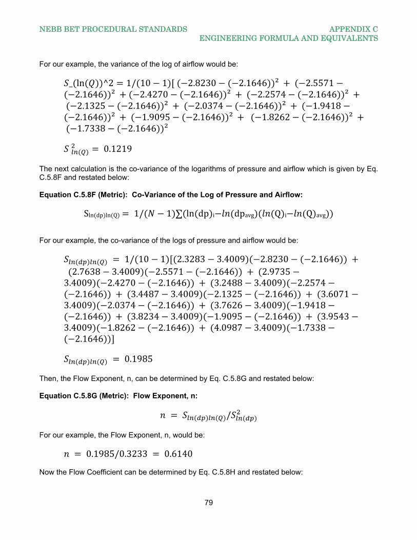
NEBB BET PROCEDURAL STANDARDS APPENDIX C ENGINEERING FORMULA AND EQUIVALENTS
79
For our example, the variance of the log of airflow would be:
_ ln ^2 1/ 10 1 2.8230 2.1646 ² 2.55712.1646 ² 2.4270 2.1646 ² 2.2574 2.1646 ²
2.1325 2.1646 ² 2.0374 2.1646 ² 1.94182.1646 ² 1.9095 2.1646 ² 1.8262 2.1646 ²
1.7338 2.1646 ²
0.1219 The next calculation is the co-variance of the logarithms of pressure and airflow which is given by Eq. C.5.8F and restated below: Equation C.5.8F (Metric): Co-Variance of the Log of Pressure and Airflow:
Sln dp ln Q 1/ 1 ∑ ln dp i dpavg Q i Q avg For our example, the co-variance of the logs of pressure and airflow would be:
1/ 10 1 2.3283 3.4009 2.8230 2.1646 2.7638 3.4009 2.5571 2.1646 2.97353.4009 2.4270 2.1646 3.2488 3.4009 2.25742.1646 3.4487 3.4009 2.1325 2.1646 3.6071
3.4009 2.0374 2.1646 3.7626 3.4009 1.94182.1646 3.8234 3.4009 1.9095 2.1646 3.9543
3.4009 1.8262 2.1646 4.0987 3.4009 1.73382.1646
0.1985
Then, the Flow Exponent, n, can be determined by Eq. C.5.8G and restated below: Equation C.5.8G (Metric): Flow Exponent, n:
/ For our example, the Flow Exponent, n, would be:
0.1985/0.3233 0.6140 Now the Flow Coefficient can be determined by Eq. C.5.8H and restated below:
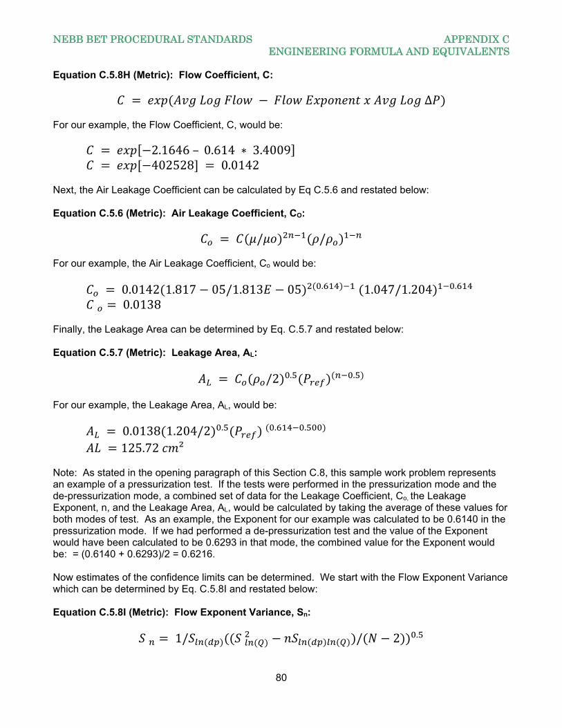
NEBB BET PROCEDURAL STANDARDS APPENDIX C ENGINEERING FORMULA AND EQUIVALENTS
80
Equation C.5.8H (Metric): Flow Coefficient, C:
∆ For our example, the Flow Coefficient, C, would be:
2.1646– 0.614 ∗ 3.4009 402528 0.0142
Next, the Air Leakage Coefficient can be calculated by Eq C.5.6 and restated below: Equation C.5.6 (Metric): Air Leakage Coefficient, CO:
/ / For our example, the Air Leakage Coefficient, Co would be:
0.0142 1.817 05/1.813 05 . 1.047/1.204 . 0.0138
Finally, the Leakage Area can be determined by Eq. C.5.7 and restated below: Equation C.5.7 (Metric): Leakage Area, AL:
/2 . .
For our example, the Leakage Area, AL, would be:
0.0138 1.204/2 . . .
125.72 ² Note: As stated in the opening paragraph of this Section C.8, this sample work problem represents an example of a pressurization test. If the tests were performed in the pressurization mode and the de-pressurization mode, a combined set of data for the Leakage Coefficient, Co, the Leakage Exponent, n, and the Leakage Area, AL, would be calculated by taking the average of these values for both modes of test. As an example, the Exponent for our example was calculated to be 0.6140 in the pressurization mode. If we had performed a de-pressurization test and the value of the Exponent would have been calculated to be 0.6293 in that mode, the combined value for the Exponent would be: = (0.6140 + 0.6293)/2 = 0.6216. Now estimates of the confidence limits can be determined. We start with the Flow Exponent Variance which can be determined by Eq. C.5.8I and restated below: Equation C.5.8I (Metric): Flow Exponent Variance, Sn:
1/ / 2 .
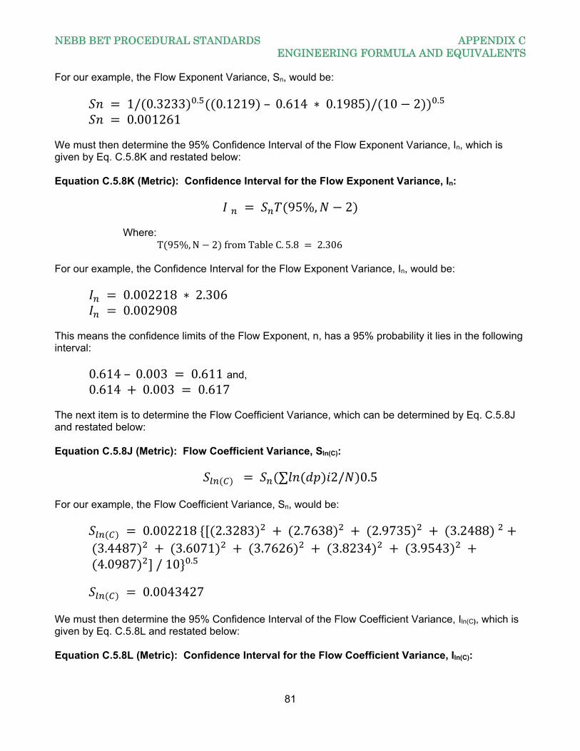
NEBB BET PROCEDURAL STANDARDS APPENDIX C ENGINEERING FORMULA AND EQUIVALENTS
81
For our example, the Flow Exponent Variance, Sn, would be:
1/ 0.3233 . 0.1219 – 0.614 ∗ 0.1985 / 10 2 . 0.001261
We must then determine the 95% Confidence Interval of the Flow Exponent Variance, In, which is given by Eq. C.5.8K and restated below: Equation C.5.8K (Metric): Confidence Interval for the Flow Exponent Variance, In:
95%, 2
Where: T 95%,N 2 fromTableC. 5.8 2.306
For our example, the Confidence Interval for the Flow Exponent Variance, In, would be:
0.002218 ∗ 2.306 0.002908
This means the confidence limits of the Flow Exponent, n, has a 95% probability it lies in the following interval:
0.614– 0.003 0.611 and,
0.614 0.003 0.617 The next item is to determine the Flow Coefficient Variance, which can be determined by Eq. C.5.8J and restated below: Equation C.5.8J (Metric): Flow Coefficient Variance, Sln(C):
∑ 2/ 0.5
For our example, the Flow Coefficient Variance, Sn, would be:
0.002218 2.3283 2.7638 2.9735 3.2488 3.4487 3.6071 3.7626 3.8234 3.9543 4.0987 /10 .
0.0043427 We must then determine the 95% Confidence Interval of the Flow Coefficient Variance, Iln(C), which is given by Eq. C.5.8L and restated below: Equation C.5.8L (Metric): Confidence Interval for the Flow Coefficient Variance, Iln(C):
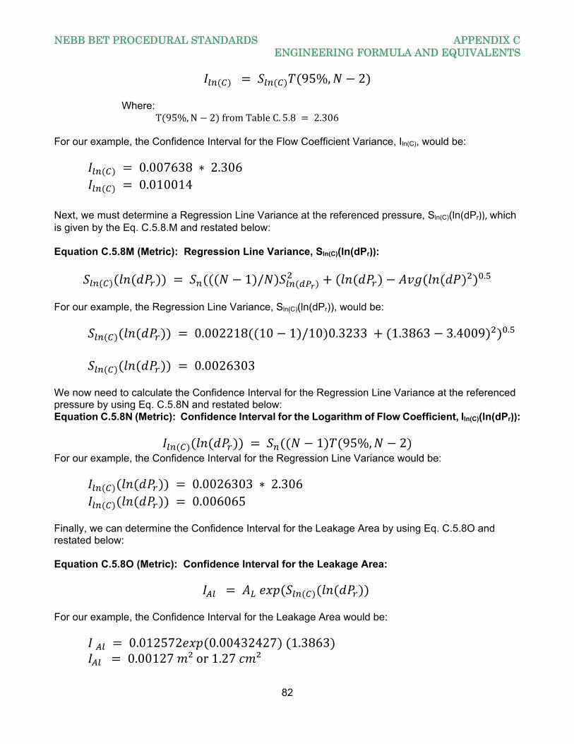
NEBB BET PROCEDURAL STANDARDS APPENDIX C ENGINEERING FORMULA AND EQUIVALENTS
82
95%, 2
Where: T 95%,N 2 fromTableC. 5.8 2.306
For our example, the Confidence Interval for the Flow Coefficient Variance, Iln(C), would be:
0.007638 ∗ 2.306 0.010014
Next, we must determine a Regression Line Variance at the referenced pressure, Sln(C)(ln(dPr)), which is given by the Eq. C.5.8.M and restated below: Equation C.5.8M (Metric): Regression Line Variance, Sln(C)(ln(dPr)):
1 / .
For our example, the Regression Line Variance, Sln(C)(ln(dPr)), would be:
0.002218 10 1 /10 0.3233 1.3863 3.4009 .
0.0026303 We now need to calculate the Confidence Interval for the Regression Line Variance at the referenced pressure by using Eq. C.5.8N and restated below: Equation C.5.8N (Metric): Confidence Interval for the Logarithm of Flow Coefficient, Iln(C)(ln(dPr)):
1 95%, 2
For our example, the Confidence Interval for the Regression Line Variance would be:
0.0026303 ∗ 2.306 0.006065
Finally, we can determine the Confidence Interval for the Leakage Area by using Eq. C.5.8O and restated below: Equation C.5.8O (Metric): Confidence Interval for the Leakage Area:
For our example, the Confidence Interval for the Leakage Area would be:
0.012572 0.00432427 1.3863 0.00127 ²or1.27 ²
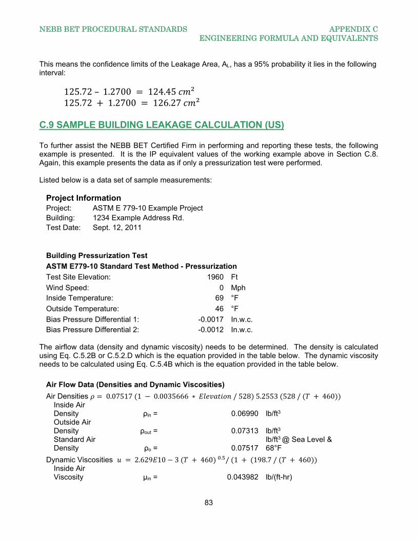
NEBB BET PROCEDURAL STANDARDS APPENDIX C ENGINEERING FORMULA AND EQUIVALENTS
83
This means the confidence limits of the Leakage Area, AL, has a 95% probability it lies in the following interval:
125.72– 1.2700 124.45 ²125.72 1.2700 126.27 ²
C.9 SAMPLE BUILDING LEAKAGE CALCULATION (US) To further assist the NEBB BET Certified Firm in performing and reporting these tests, the following example is presented. It is the IP equivalent values of the working example above in Section C.8. Again, this example presents the data as if only a pressurization test were performed. Listed below is a data set of sample measurements:
Project Information Project: ASTM E 779-10 Example Project Building: 1234 Example Address Rd. Test Date: Sept. 12, 2011
Building Pressurization Test
ASTM E779-10 Standard Test Method - Pressurization
Test Site Elevation: 1960 Ft
Wind Speed: 0 Mph Inside Temperature: 69 °F
Outside Temperature: 46 °F
Bias Pressure Differential 1: -0.0017 In.w.c. Bias Pressure Differential 2: -0.0012 In.w.c.
The airflow data (density and dynamic viscosity) needs to be determined. The density is calculated using Eq. C.5.2B or C.5.2.D which is the equation provided in the table below. The dynamic viscosity needs to be calculated using Eq. C.5.4B which is the equation provided in the table below.
Air Flow Data (Densities and Dynamic Viscosities)
Air Densities 0.07517 1 0.0035666 ∗ / 528 5.2553 528/ 460
Inside Air Density ρin = 0.06990 lb/ft3
Outside Air Density ρout = 0.07313 lb/ft3
Standard Air Density ρo = 0.07517
lb/ft3 @ Sea Level & 68°F
Dynamic Viscosities 2.629 10 3 460 . / 1 198.7 / 460
Inside Air Viscosity μin = 0.043982 lb/(ft-hr)
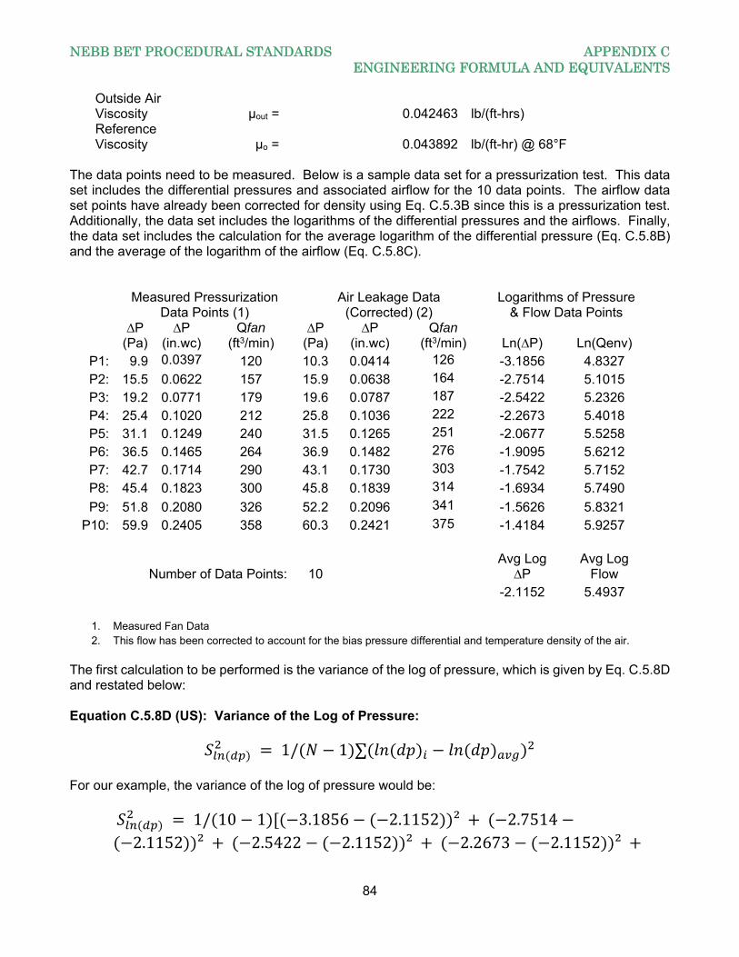
NEBB BET PROCEDURAL STANDARDS APPENDIX C ENGINEERING FORMULA AND EQUIVALENTS
84
Outside Air Viscosity μout = 0.042463 lb/(ft-hrs)
Reference Viscosity μo = 0.043892 lb/(ft-hr) @ 68°F
The data points need to be measured. Below is a sample data set for a pressurization test. This data set includes the differential pressures and associated airflow for the 10 data points. The airflow data set points have already been corrected for density using Eq. C.5.3B since this is a pressurization test. Additionally, the data set includes the logarithms of the differential pressures and the airflows. Finally, the data set includes the calculation for the average logarithm of the differential pressure (Eq. C.5.8B) and the average of the logarithm of the airflow (Eq. C.5.8C).
Measured Pressurization
Data Points (1) Air Leakage Data
(Corrected) (2) Logarithms of Pressure
& Flow Data Points
∆P
(Pa) ∆P
(in.wc) Qfan
(ft3/min) ∆P
(Pa) ∆P
(in.wc) Qfan
(ft3/min) Ln(∆P) Ln(Qenv) P1: 9.9 0.0397 120 10.3 0.0414 126 -3.1856 4.8327 P2: 15.5 0.0622 157 15.9 0.0638 164 -2.7514 5.1015 P3: 19.2 0.0771 179 19.6 0.0787 187 -2.5422 5.2326 P4: 25.4 0.1020 212 25.8 0.1036 222 -2.2673 5.4018 P5: 31.1 0.1249 240 31.5 0.1265 251 -2.0677 5.5258 P6: 36.5 0.1465 264 36.9 0.1482 276 -1.9095 5.6212 P7: 42.7 0.1714 290 43.1 0.1730 303 -1.7542 5.7152 P8: 45.4 0.1823 300 45.8 0.1839 314 -1.6934 5.7490
P9: 51.8 0.2080 326 52.2 0.2096 341 -1.5626 5.8321 P10: 59.9 0.2405 358 60.3 0.2421 375 -1.4184 5.9257
Number of Data Points: 10
Avg Log
∆P Avg Log
Flow -2.1152 5.4937
1. Measured Fan Data 2. This flow has been corrected to account for the bias pressure differential and temperature density of the air.
The first calculation to be performed is the variance of the log of pressure, which is given by Eq. C.5.8D and restated below: Equation C.5.8D (US): Variance of the Log of Pressure:
1/ 1 ∑ For our example, the variance of the log of pressure would be:
1/ 10 1 3.1856 2.1152 ² 2.75142.1152 ² 2.5422 2.1152 ² 2.2673 2.1152 ²
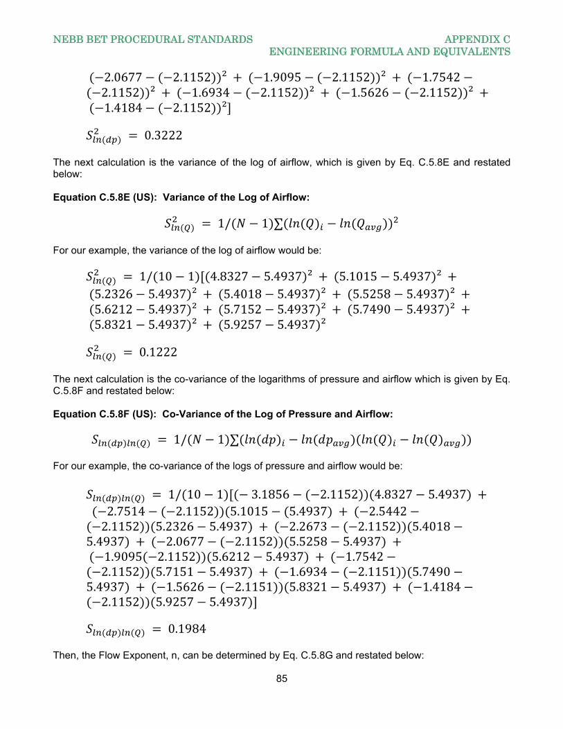
NEBB BET PROCEDURAL STANDARDS APPENDIX C ENGINEERING FORMULA AND EQUIVALENTS
85
2.0677 2.1152 ² 1.9095 2.1152 ² 1.75422.1152 ² 1.6934 2.1152 ² 1.5626 2.1152 ²
1.4184 2.1152 ²
0.3222 The next calculation is the variance of the log of airflow, which is given by Eq. C.5.8E and restated below: Equation C.5.8E (US): Variance of the Log of Airflow:
1/ 1 ∑ For our example, the variance of the log of airflow would be:
1/ 10 1 4.8327 5.4937 ² 5.1015 5.4937 ² 5.2326 5.4937 ² 5.4018 5.4937 ² 5.5258 5.4937 ² 5.6212 5.4937 ² 5.7152 5.4937 ² 5.7490 5.4937 ² 5.8321 5.4937 ² 5.9257 5.4937 ²
0.1222 The next calculation is the co-variance of the logarithms of pressure and airflow which is given by Eq. C.5.8F and restated below: Equation C.5.8F (US): Co-Variance of the Log of Pressure and Airflow:
1/ 1 ∑ For our example, the co-variance of the logs of pressure and airflow would be:
1/ 10 1 3.1856 2.1152 4.8327 5.4937
2.7514 2.1152 5.1015 5.4937 2.54422.1152 5.2326 5.4937 2.2673 2.1152 5.4018
5.4937 2.0677 2.1152 5.5258 5.4937 1.9095 2.1152 5.6212 5.4937 1.75422.1152 5.7151 5.4937 1.6934 2.1151 5.7490
5.4937 1.5626 2.1151 5.8321 5.4937 1.41842.1152 5.9257 5.4937
0.1984 Then, the Flow Exponent, n, can be determined by Eq. C.5.8G and restated below:
NEBB BET PROCEDURAL STANDARDS APPENDIX C ENGINEERING FORMULA AND EQUIVALENTS
86
Equation C.5.8G (US): Flow Exponent, n:
/ For our example, the Flow Exponent, n, would be:
0.1984/0.3222 0.616 Now the Flow Coefficient can be determined by Eq. C.5.8H and restated below: Equation C.5.8H (Metric): Flow Coefficient, C:
∗ ∆ For our example, the Flow Coefficient, C, would be:
5.4937– 0.616 2.1152 6.7965 894.78 / . . .
Next, the Air Leakage Coefficient can be calculated by Eq. C.5.6 and restated below: Equation C.5.6 (US): Air Leakage Coefficient, CO:
/ / For our example, the Air Leakage Coefficient, Co would be:
894.78 0.043982/0.043892 . 0.06990/0.07517 . 870.5561 / . .
Finally, the Leakage Area can be determined by Eq. C.5.7 and restated below: Equation C.5.7 (US): Leakage Area, AL:
0.1855 /2 . .
For our example, the Leakage Area, AL, would be:
0.1855 ∗ 870.556 0.07517/2 . 0.01606 . . 19.39 ² 0.1347 ²
Note: As stated in the opening paragraph of this Section C.8, this sample work problem represents an example of a pressurization test. If the tests were performed in the pressurization mode and the de-pressurization mode, a combined set of data for the Leakage Coefficient, Co, the Leakage Exponent, n, and the Leakage Area, AL, would be calculated by taking the average of these values for both modes of test. As an example, the Exponent for our example was calculated to be 0.6140 in the
NEBB BET PROCEDURAL STANDARDS APPENDIX C ENGINEERING FORMULA AND EQUIVALENTS
87
pressurization mode. If we had performed a de-pressurization test and the value of the Exponent would have been calculated to be 0.6293 in that mode, the combined value for the Exponent would be: = (0.6160 + 0.6289)/2 = 0.6224. Now estimates of the confidence limits can be determined. We start with the Flow Exponent Variance which can be determined by Eq. C.5.8I and restated below: Equation C.5.8I (US): Flow Exponent Variance, Sn:
1/ / 2 . For our example, the Flow Exponent Variance, Sn, would be:
1/ 0.3222 . 0.1222 – 0.616 ∗ 0.1984 / 10 2 . 0.001496
We must then determine the 95% Confidence Interval of the Flow Exponent Variance, In, which is given by Eq. C.5.8K and restated below: Equation C.5.8K (US): Confidence Interval for the Flow Exponent Variance, In:
95%, 2
Where:
95%, 2 fromTableC. 5.8 2.306 For our example, the Confidence Interval for the Flow Exponent Variance, In, would be:
0.001496 ∗ 2.306 0.003449
This means the confidence limits of the Flow Exponent, n, has a 95% probability it lies in the following interval:
0.616– 0.003 0.613 and, 0.616 0.003 0.619
The next item is to determine the Flow Coefficient Variance, which can be determined by Eq. C.5.8J and restated below: Equation C.5.8J (US): Flow Coefficient Variance, Sln(C):
∑ / .
For our example, the Flow Coefficient Variance, Sn, would be:
NEBB BET PROCEDURAL STANDARDS APPENDIX C ENGINEERING FORMULA AND EQUIVALENTS
88
0.001496 3.1856 2.7514 2.5422 2.2673 2.0677 1.9095 1.7542 1.6934 1.5626 1.4184 /10 .
0.003265 We must then determine the 95% Confidence Interval of the Flow Coefficient Variance, Iln(C), which is given by Eq. C.5.8L and restated below: Equation C.5.8L (US): Confidence Interval for the Flow Coefficient Variance, Iln(C):
95%, 2
Where: 95%, 2 fromTableC. 5.8 2.306
For our example, the Confidence Interval for the Flow Coefficient Variance, Iln(C), would be:
0.003265 ∗ 2.306 0.007529
Next, we must determine a Regression Line Variance at the referenced pressure, ,
which is given by the Eq. C.5.8.M and restated below: Equation C.5.8M (US): Regression Line Variance, Sln(C)(ln(dPr)):
1 / .
For our example, the Regression Line Variance, Sln(C)(ln(dPr)), would be:
0.001496 10 1 /10 ∗ 0.3222 4.131423.4009 . 0.003122
We now need to calculate the Confidence Interval for the Regression Line Variance at the referenced pressure by using Eq. C.5.8N and restated below: Equation C.5.8N (US): Confidence Interval for the Logarithm of Flow Coefficient, Iln(C)(ln(dPr)):
1 95%, 2 For our example, the Confidence Interval for the Regression Line Variance would be:
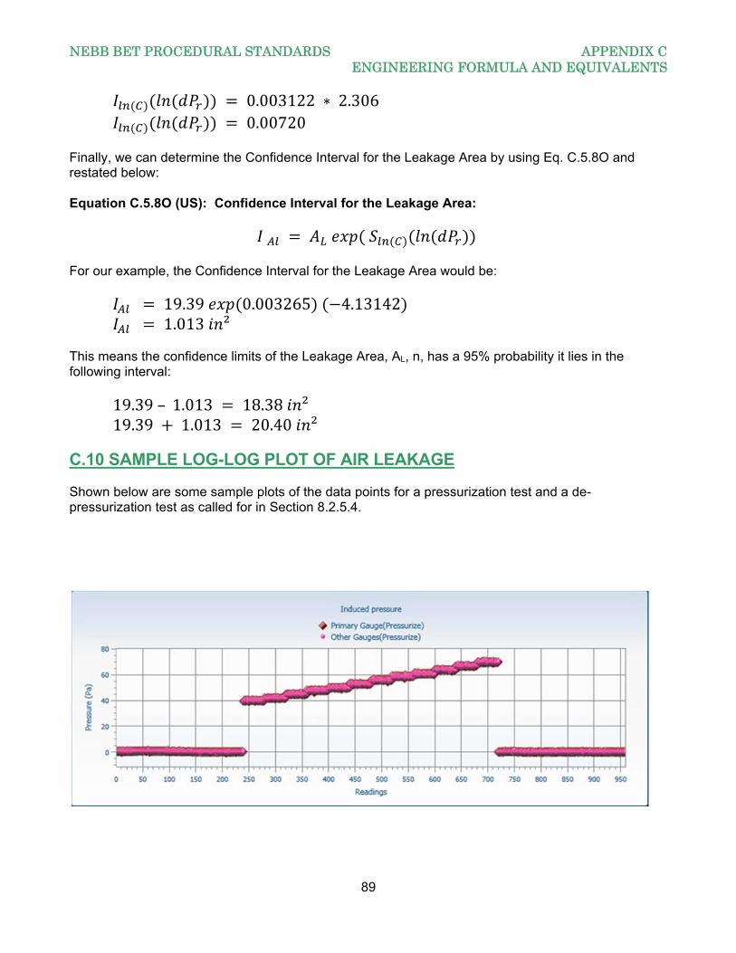
NEBB BET PROCEDURAL STANDARDS APPENDIX C ENGINEERING FORMULA AND EQUIVALENTS
89
0.003122 ∗ 2.306 0.00720
Finally, we can determine the Confidence Interval for the Leakage Area by using Eq. C.5.8O and restated below: Equation C.5.8O (US): Confidence Interval for the Leakage Area:
For our example, the Confidence Interval for the Leakage Area would be:
19.39 0.003265 4.13142 1.013 ²
This means the confidence limits of the Leakage Area, AL, n, has a 95% probability it lies in the following interval:
19.39– 1.013 18.38 ²19.39 1.013 20.40 ²
C.10 SAMPLE LOG-LOG PLOT OF AIR LEAKAGE Shown below are some sample plots of the data points for a pressurization test and a de-pressurization test as called for in Section 8.2.5.4.
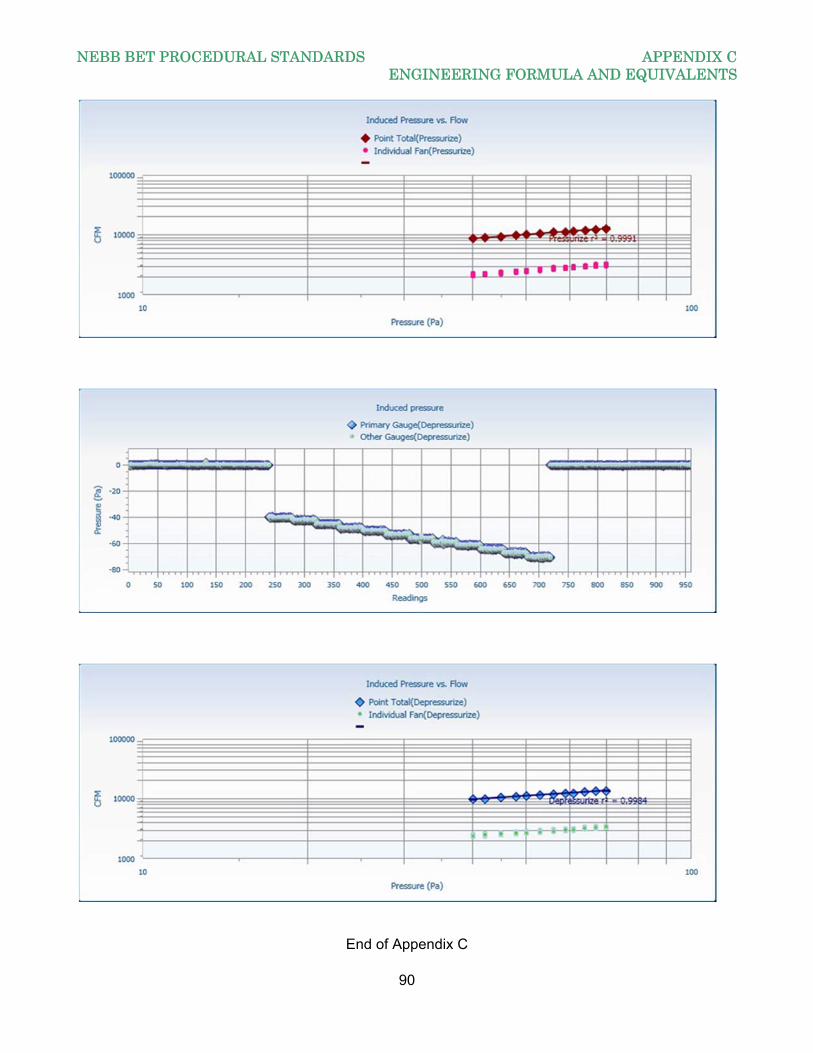
NEBB BET PROCEDURAL STANDARDS APPENDIX C ENGINEERING FORMULA AND EQUIVALENTS
90
End of Appendix C
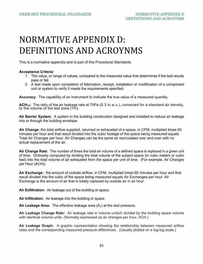
NEBB BET PROCEDURAL STANDARDS NORMATIVE APPENDIX D DEFINITIONS AND ACRONYMS
91
NORMATIVEAPPENDIXD:DEFINITIONSANDACROYNMSThis is a normative appendix and is part of this Procedural Standards.
Acceptance Criteria:
1. The value, or range of values, compared to the measured value that determines if the test results pass or fail.
2. A test made upon completion of fabrication, receipt, installation or modification of a component unit or system to verify it meets the requirements specified.
Accuracy: The capability of an instrument to indicate the true value of a measured quantity. ACH75: The ratio of the air leakage rate at 75Pa (0.3 in.w.c.), corrected for a standard air density, to the volume of the test zone (1/h). Air Barrier System: A system in the building construction designed and installed to reduce air leakage into or through the building envelope.
Air Change: the total airflow supplied, returned or exhausted of a space, in CFM, multiplied times 60 minutes per hour and that result divided into the cubic footage of the space being measured equals Total Air Changes per hour. Air Changes can be the same air recirculated over and over with no actual replacement of the air.
Air Change Rate: The number of times the total air volume of a defined space is replaced in a given unit of time. Ordinarily computed by dividing the total volume of the subject space (in cubic meters or cubic feet) into the total volume of air exhausted from the space per unit of time. (For example, Air Changes per Hour (ACH))
Air Exchange: the amount of outside airflow, in CFM, multiplied times 60 minutes per hour and that result divided into the cubic of the space being measured equals Air Exchanges per hour. Air Exchange is the amount of air that is totally replaced by outside air in an hour.
Air Exfiltration: Air leakage out of the building or space. Air Infiltration: Air leakage into the building or space. Air Leakage Area: The effective leakage area (AL) at the test pressure. Air Leakage Change Rate: Air leakage rate in volume units/h divided by the building space volume with identical volume units. (Normally expressed as air changes per hour, ACH.) Air Leakage Graph: A graphic representation showing the relationship between measured airflow rates and the corresponding measured pressure differences. (Usually plotted on a log-log scale.)
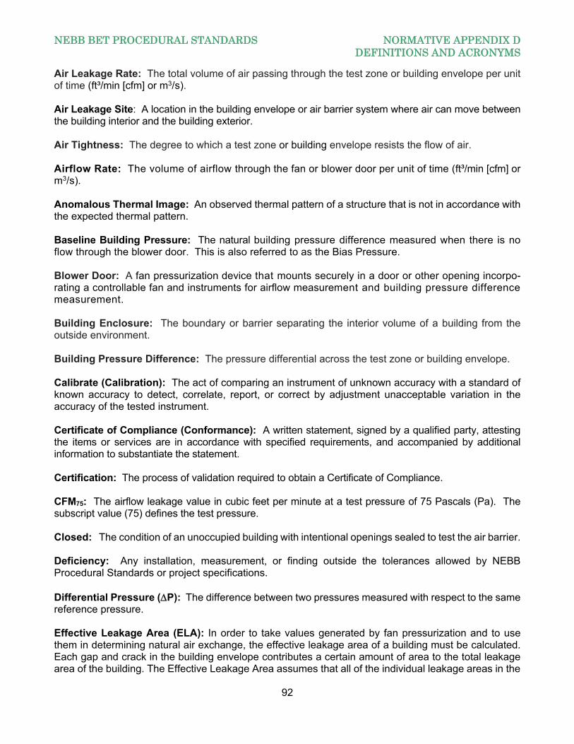
NEBB BET PROCEDURAL STANDARDS NORMATIVE APPENDIX D DEFINITIONS AND ACRONYMS
92
Air Leakage Rate: The total volume of air passing through the test zone or building envelope per unit of time (ft³/min [cfm] or m3/s). Air Leakage Site: A location in the building envelope or air barrier system where air can move between the building interior and the building exterior. Air Tightness: The degree to which a test zone or building envelope resists the flow of air. Airflow Rate: The volume of airflow through the fan or blower door per unit of time (ft³/min [cfm] or m3/s). Anomalous Thermal Image: An observed thermal pattern of a structure that is not in accordance with the expected thermal pattern. Baseline Building Pressure: The natural building pressure difference measured when there is no flow through the blower door. This is also referred to as the Bias Pressure. Blower Door: A fan pressurization device that mounts securely in a door or other opening incorpo-rating a controllable fan and instruments for airflow measurement and building pressure difference measurement. Building Enclosure: The boundary or barrier separating the interior volume of a building from the outside environment. Building Pressure Difference: The pressure differential across the test zone or building envelope. Calibrate (Calibration): The act of comparing an instrument of unknown accuracy with a standard of known accuracy to detect, correlate, report, or correct by adjustment unacceptable variation in the accuracy of the tested instrument. Certificate of Compliance (Conformance): A written statement, signed by a qualified party, attesting the items or services are in accordance with specified requirements, and accompanied by additional information to substantiate the statement. Certification: The process of validation required to obtain a Certificate of Compliance. CFM75: The airflow leakage value in cubic feet per minute at a test pressure of 75 Pascals (Pa). The subscript value (75) defines the test pressure. Closed: The condition of an unoccupied building with intentional openings sealed to test the air barrier. Deficiency: Any installation, measurement, or finding outside the tolerances allowed by NEBB Procedural Standards or project specifications. Differential Pressure (P): The difference between two pressures measured with respect to the same reference pressure. Effective Leakage Area (ELA): In order to take values generated by fan pressurization and to use them in determining natural air exchange, the effective leakage area of a building must be calculated. Each gap and crack in the building envelope contributes a certain amount of area to the total leakage area of the building. The Effective Leakage Area assumes that all of the individual leakage areas in the
NEBB BET PROCEDURAL STANDARDS NORMATIVE APPENDIX D DEFINITIONS AND ACRONYMS
93
building are combined into a single idealized orifice or hole. The ELA will change depending on the reference pressure used to calculate it. Enclosure: The construction, taken as a whole or in part, that separates the indoors of a building from the outdoors. Equivalent Leakage Area (EqLA): Usually taken at 10Pa using 0.61 discharge coefficient, but for the purposes of this Specification, it is taken at 75Pa. Field-of-View (FOV): The total angular dimensions, expressed in degrees or radians, within which objects can be imaged, displayed, and recorded by a stationary imaging device. Framing Spacing: Distance between the centerlines of joists, studs, or rafters. Function: The particular type of data measurement specified in NEBB Standards for Instrumentation and Calibration. Informative Appendices: The normative appendices to NEBB Procedural Standards are considered to be integral parts of the mandatory requirements of the Procedural Standards, which, for reasons of convenience, are placed apart from all other normative elements. Infrared Imaging System: An instrument that converts the spatial variations in infrared radiance from a surface into a two-dimensional image of that surface, in which variations in radiance are displayed as a range of colors or tones. Infrared Thermography: The process of generating thermal images that represent temperature and emittance variations over the surfaces of objects. Instantaneous Field of View (IFOV): The smallest angle, in milliradians, that can be instantaneously resolved by a particular infrared imaging system. Intentional Opening: Openings within the envelope designed to remain open to atmosphere during the buildings operation. Intentional openings include air intake, exhaust louvers, pressure relief dampers or louvers, dryer and exhaust vents, combustion flues and any other leakage site designed to remain open during the buildings normal operation. Windows, doors, conduits, mechanical piping, sleeves and structural steel are not considered intentional openings. M³/S75: The airflow leakage value in cubic meters per second at a test pressure of 75 Pascals (Pa). The subscript value defines the test pressure. Masonry Veneer: Frame construction with a non-load bearing exterior masonry surface. May: Indicates a course of action permissible as determined by the NEBB Certified Firm. Minimum Resolvable Temperature Difference (MRTD): A measure of the ability of the operators of an infrared imaging system to discern temperature differences with that system. The MRTD is the minimum temperature difference between a four-slot test pattern of defined shape and size and its blackbody background at which an average observer can discriminate the pattern with that infrared imaging system at a defined distance.
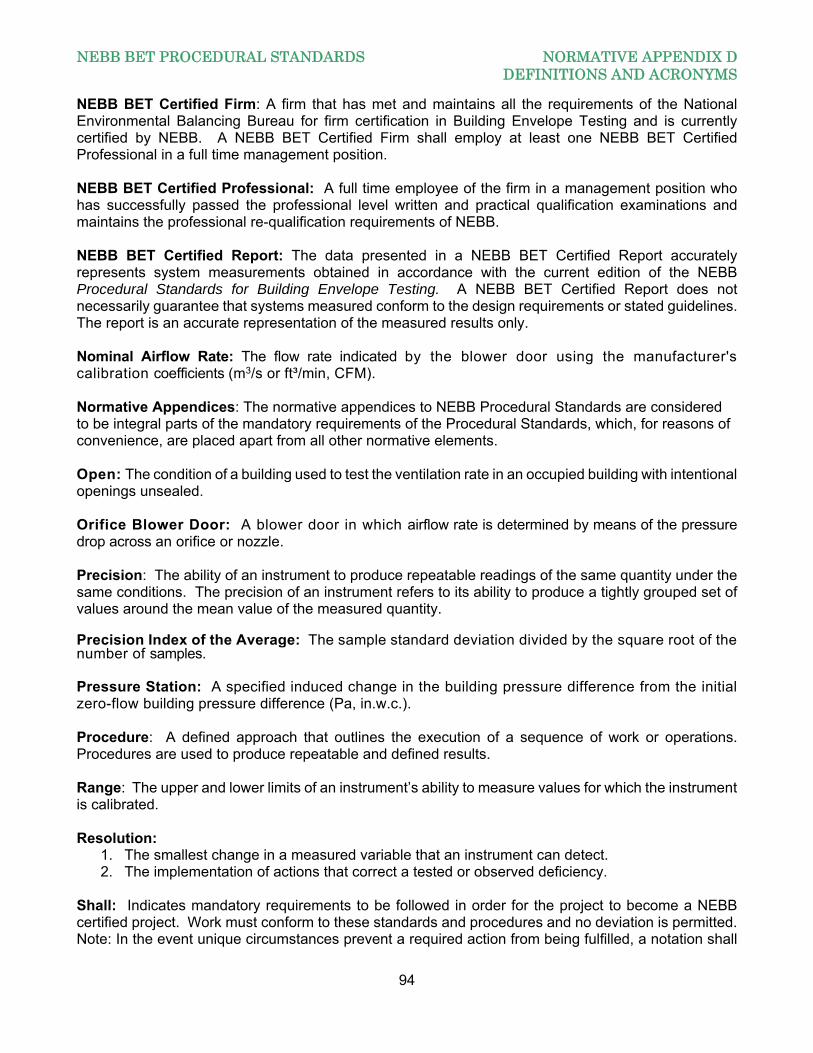
NEBB BET PROCEDURAL STANDARDS NORMATIVE APPENDIX D DEFINITIONS AND ACRONYMS
94
NEBB BET Certified Firm: A firm that has met and maintains all the requirements of the National Environmental Balancing Bureau for firm certification in Building Envelope Testing and is currently certified by NEBB. A NEBB BET Certified Firm shall employ at least one NEBB BET Certified Professional in a full time management position. NEBB BET Certified Professional: A full time employee of the firm in a management position who has successfully passed the professional level written and practical qualification examinations and maintains the professional re-qualification requirements of NEBB. NEBB BET Certified Report: The data presented in a NEBB BET Certified Report accurately represents system measurements obtained in accordance with the current edition of the NEBB Procedural Standards for Building Envelope Testing. A NEBB BET Certified Report does not necessarily guarantee that systems measured conform to the design requirements or stated guidelines. The report is an accurate representation of the measured results only. Nominal Airflow Rate: The flow rate indicated by the blower door using the manufacturer's calibration coefficients (m3/s or ft³/min, CFM). Normative Appendices: The normative appendices to NEBB Procedural Standards are considered to be integral parts of the mandatory requirements of the Procedural Standards, which, for reasons of convenience, are placed apart from all other normative elements. Open: The condition of a building used to test the ventilation rate in an occupied building with intentional openings unsealed. Orifice Blower Door: A blower door in which airflow rate is determined by means of the pressure drop across an orifice or nozzle. Precision: The ability of an instrument to produce repeatable readings of the same quantity under the same conditions. The precision of an instrument refers to its ability to produce a tightly grouped set of values around the mean value of the measured quantity. Precision Index of the Average: The sample standard deviation divided by the square root of the number of samples. Pressure Station: A specified induced change in the building pressure difference from the initial zero-flow building pressure difference (Pa, in.w.c.). Procedure: A defined approach that outlines the execution of a sequence of work or operations. Procedures are used to produce repeatable and defined results. Range: The upper and lower limits of an instrument’s ability to measure values for which the instrument is calibrated. Resolution:
1. The smallest change in a measured variable that an instrument can detect. 2. The implementation of actions that correct a tested or observed deficiency.
Shall: Indicates mandatory requirements to be followed in order for the project to become a NEBB certified project. Work must conform to these standards and procedures and no deviation is permitted. Note: In the event unique circumstances prevent a required action from being fulfilled, a notation shall
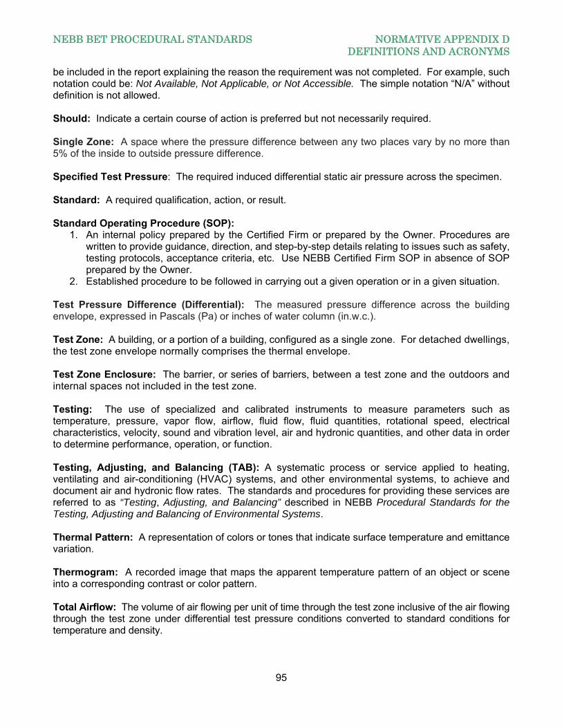
NEBB BET PROCEDURAL STANDARDS NORMATIVE APPENDIX D DEFINITIONS AND ACRONYMS
95
be included in the report explaining the reason the requirement was not completed. For example, such notation could be: Not Available, Not Applicable, or Not Accessible. The simple notation “N/A” without definition is not allowed. Should: Indicate a certain course of action is preferred but not necessarily required. Single Zone: A space where the pressure difference between any two places vary by no more than 5% of the inside to outside pressure difference. Specified Test Pressure: The required induced differential static air pressure across the specimen. Standard: A required qualification, action, or result. Standard Operating Procedure (SOP):
1. An internal policy prepared by the Certified Firm or prepared by the Owner. Procedures are written to provide guidance, direction, and step-by-step details relating to issues such as safety, testing protocols, acceptance criteria, etc. Use NEBB Certified Firm SOP in absence of SOP prepared by the Owner.
2. Established procedure to be followed in carrying out a given operation or in a given situation. Test Pressure Difference (Differential): The measured pressure difference across the building envelope, expressed in Pascals (Pa) or inches of water column (in.w.c.). Test Zone: A building, or a portion of a building, configured as a single zone. For detached dwellings, the test zone envelope normally comprises the thermal envelope. Test Zone Enclosure: The barrier, or series of barriers, between a test zone and the outdoors and internal spaces not included in the test zone. Testing: The use of specialized and calibrated instruments to measure parameters such as temperature, pressure, vapor flow, airflow, fluid flow, fluid quantities, rotational speed, electrical characteristics, velocity, sound and vibration level, air and hydronic quantities, and other data in order to determine performance, operation, or function. Testing, Adjusting, and Balancing (TAB): A systematic process or service applied to heating, ventilating and air-conditioning (HVAC) systems, and other environmental systems, to achieve and document air and hydronic flow rates. The standards and procedures for providing these services are referred to as “Testing, Adjusting, and Balancing” described in NEBB Procedural Standards for the Testing, Adjusting and Balancing of Environmental Systems. Thermal Pattern: A representation of colors or tones that indicate surface temperature and emittance variation. Thermogram: A recorded image that maps the apparent temperature pattern of an object or scene into a corresponding contrast or color pattern. Total Airflow: The volume of air flowing per unit of time through the test zone inclusive of the air flowing through the test zone under differential test pressure conditions converted to standard conditions for temperature and density.

NEBB BET PROCEDURAL STANDARDS NORMATIVE APPENDIX D DEFINITIONS AND ACRONYMS
96
Unit of Length: The sum of all perimeters of operable ventilators, sash, or doors that are contained in the test specimen based on overall dimensions of such parts. Where two such operable parts meet two adjacent lengths of perimeter shall be counted as only one length. Zone: A volume of building served by a single ventilation system. For buildings with natural ventilation only, the whole building is considered a zone.
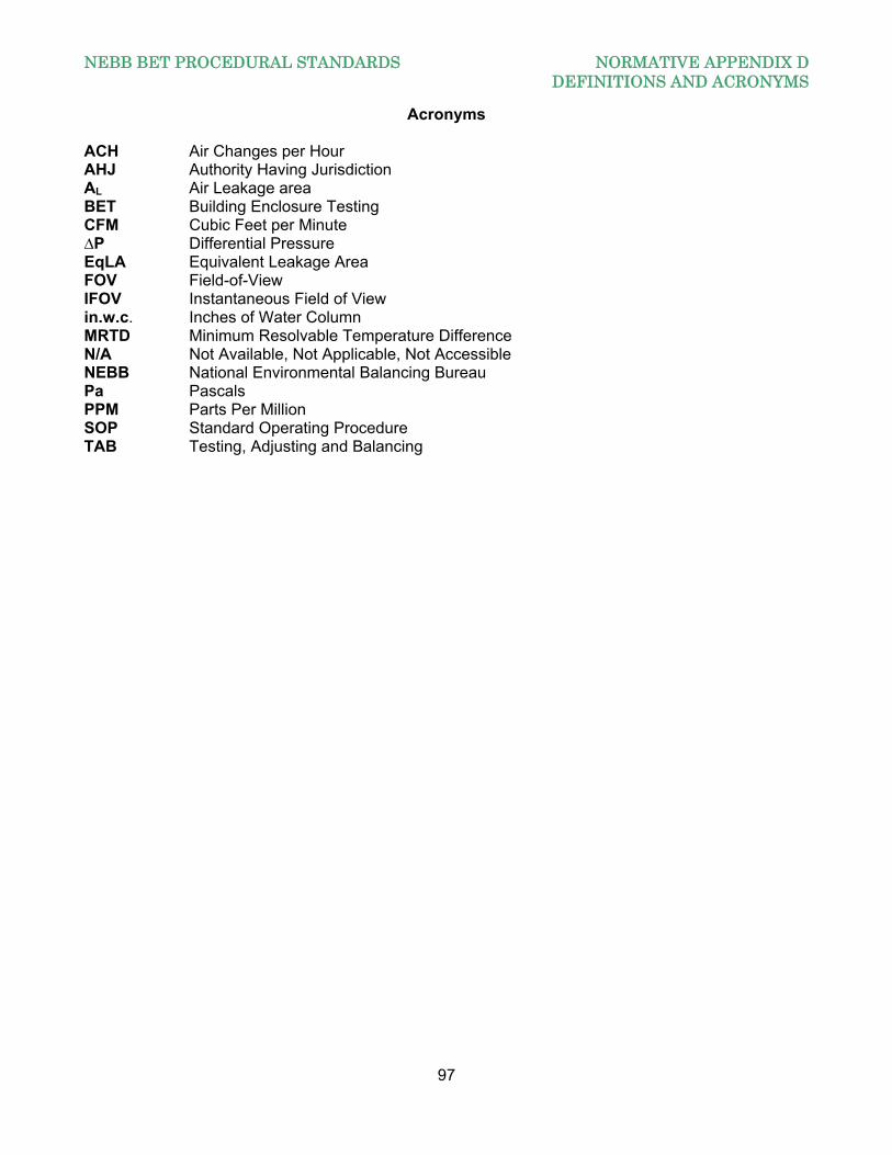
NEBB BET PROCEDURAL STANDARDS NORMATIVE APPENDIX D DEFINITIONS AND ACRONYMS
97
Acronyms ACH Air Changes per Hour AHJ Authority Having Jurisdiction AL Air Leakage area BET Building Enclosure Testing CFM Cubic Feet per Minute ∆P Differential Pressure EqLA Equivalent Leakage Area FOV Field-of-View IFOV Instantaneous Field of View in.w.c. Inches of Water Column MRTD Minimum Resolvable Temperature Difference N/A Not Available, Not Applicable, Not Accessible NEBB National Environmental Balancing Bureau Pa Pascals PPM Parts Per Million SOP Standard Operating Procedure TAB Testing, Adjusting and Balancing
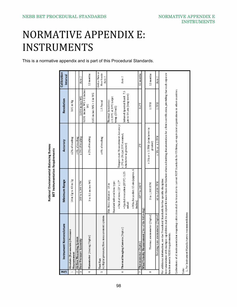
NEBB BET PROCEDURAL STANDARDS NORMATIVE APPENDIX E INSTRUMENTS
98
NORMATIVEAPPENDIXE:INSTRUMENTSThis is a normative appendix and is part of this Procedural Standards.