Embed Size (px)
Citation preview

TP 3668 E
Transport Transports Canada Canada
STANDARDS FOR NAVIGATING
APPLIANCES AND EQUIPMENT
MARINE SAFETY DIRECTORATE TRANSPORT CANADA
OTTAWA

1983

FOREWORD
The International Convention for the Safety of Life at Sea, 1974 (SOLAS) requires navigating appliances and equipment to conform with appropriate performance standards not less than those adopted by the International Maritime organization (IMO).
Member governments are urged to accept navigating appliances and equipment on foreign flag ships where these comply with IMO standards and base such acceptance on the flag state's proof of compliance.
The Coast Guard accepts these principles and the Navigating Appliances and Equipment Regulations require such appliances and equipment to at least comply with:
(a) these Standards for Navigating Appliances and Equipment, 1983, TP 3668 when fitted on Canadian ships; and
(b) the IMO performance standards when fitted on non-Canadian ships.
The standards described in this document are generally based on IMO recommendations; however, the Coast Guard may adopt other standards developed by reputable national or international organizations where IMO standards do not exist.
In addition, the Coast Guard may require special provisions relating to design, construction and operational performance where there is a clear need for such special conditions. Where the IMO standards are modified or supplemented by special Canadian provisions, these provisions have been underlined to identify where the differences occur.
These standards do not supersede those published by the Department of Communications (DOC) for radio equipment or applicable Coast Guard installation specifications. These documents can be obtained by writing to any DOC or Coast Guard office, as applicable.
- 2 -
CONTENTS Page
FOREWORD ................................................................................................................................. 1
CONTENTS ................................................................................................................................... 2
1 INTRODUCTION ........................................................................................................................ 3
2. CERTIFICATION....................................................................................................................... 4
3 INSPECTION.............................................................................................................................. 6
4 GENERAL REQUIREMENTS .................................................................................................. 7
5 STANDARDS FOR MAGNETIC COMPASSES................................................................... 9
6 STANDARDS FOR GYRO-COMPASSES ..........................................................................14
7 STANDARDS FOR AUTOMATIC PILOTS...........................................................................19
8 STANDARDS FOR RADAR..................................................................................................22
9 STANDARDS FOR AUTOMATIC RADAR PLOTTING AIDS (ARPA)..............................32
10 STANDARDS FOR RADIO DIRECTION-FINDING SYSTEMS .......................................45
11 STANDARDS FOR ELECTRONIC POSITION FIXING EQUIPMENT ............................50
11.1 LORAN-C System..................................................................................................50 11.2 SATELLITE NAVIGATION SYSTEM (SATNAV)................................................61 11.3 DIFFERENTIAL OMEGA ......................................................................................61
12 STANDARDS FOR AN ECHO-SOUNDER.......................................................................71
13 STANDARDS FOR DEVICES TO INDICATE SPEED AND DISTANCE......................74
14 STANDARDS FOR RATE-OF-TURN INDICATORS ........................................................76
15 INFORMATION TO BE INCLUDED IN MANOEUVRING BOOKLETS ...........................78
- 3 -
1 INTRODUCTION 1.1 These standards apply to navigating appliances and equipment required to
be fitted on board Canadian ships. These standards are also recommended for voluntarily fitted equipment.
1.2 Navigating appliances and equipment installed on, or after the effective date
described in each standard must comply with these standards. 1.3 These standards are generally based on international standards. 1.4 These standards are the minimum requirements and may be exceeded by a
manufacturer. 1.5 Where changes have been made to the IMO standards to meet specific
Canadian requirements these changes are underlined. 1.6 Those navigating appliances and equipment that emit hertzian waves fall into
the category of radio apparatus and thereby require additional approval from the Department of Communications (DOC) to ensure that compliance with their regulations, standards and specifications are also met. DOC has the Canadian responsibility for administering the radio spectrum and may be contacted through their local district offices for information on their requirements.
1.7 The electrical systems connecting navigating appliances and equipment to a
power supply must comply with the Ship Safety Electrical Standards, TP 127. 1.8 The Chairman of the Board of Steamship Inspection may, on request, allow
any other fitting, material, appliance, installation, equipment or apparatus, or type thereof, to be fitted or carried, or any other provision to be made in that ship if he is satisfied by trial thereof or otherwise that such fitting, material, appliance, installation, equipment or apparatus, or type thereof, or provision, is at least as effective as that required by these standards.

- 4 -
2. CERTIFICATION 2.1 The Coast Guard will not type approve or certify navigating appliances and
equipment. 2.2 Navigating appliances and equipment, installed after the effective date for
each standard, must be provided with proof of compliance. 2.3 “Proof of compliance” means a document or label stating that the appliance
or equipment is designed and manufactured to meet the standards described in
.1 this publication; or
.2 appropriate IMO Resolutions.
2.4 Proof of compliance for appliances and equipment shall be in the form of:
.1 a certificate of compliance;
.2 a declaration of compliance; or
.3 a label affixed to the appliance or equipment. 2.5 Proof of compliance for appliances and equipment may be issued by:
.1 a government that is party to the 1974 SOLAS Convention;
.2 a classification society;
.3 an independent testing establishment; or
.4 the manufacturer. 2.6 The proof of compliance issued by a classification society, independent
testing centre or manufacturer must be recognized by a government, that is party to the 1974 SOLAS Convention, for the fitting of such appliances and equipment on board its ships.
2.7 Proof of compliance written in a language other than English or French, shall
be accompanied by an English or French translation.
- 5 -
2.8 Acceptance of the proof of compliance is subject to the same conditions under which it was originally issued.
2.9 Documentation containing technical details shall support the proof of
compliance and be retained on file by the person or authority issuing such proof of compliance.
2.10 The Coast Guard may require information necessary to evaluate whether the
appliance or equipment meets these standards. 2.11 Where a label is used as proof of compliance, it must be affixed to the
appliance or equipment. 2.12 The label shall identify the issuing company and indicate that the item is
"designed and manufactured to comply with DOT-TP 3668”. The label must be indelible, tamper-proof and affixed in such a manner as not to be removable except by destruction or defacing.
2.13 Proof of compliance issued under these standards may be invalidated if
evidence shows that such proof was improperly issued or contains incorrect information.
- 6 -
3 INSPECTION 3.1 Marine surveyors may require proof of compliance for any appliances and
equipment fitted after the effective date for each standard. 3.2 Proof of compliance should be kept on board and be available for inspection
by a marine surveyor and/or radio inspector. 3.3 Inspection may include the operation of the appliance or equipment to ensure
that it is in proper working order. 3.4 Safety inspection certificates may be withheld if the required appliance or
equipment does not comply with the requirements of these standards or the electrical installation requirements identified in the Ship Safety Electrical Standards, TP 127.
3.5 Where the size or special purpose of a ship makes it unreasonable or
impossible to comply with the measures to ensure electromagnetic compatibility and with minimum safe siting distances between various types of appliances and equipment, the marine surveyor shall, after consultation with the owner or his representative, determine the most practical and serviceable siting for the appliance or equipment which best meets the provisions of these standards.
- 7 -
4 GENERAL REQUIREMENTS 4.1 INTRODUCTION 4.1.1 Equipment required by the Navigating Appliances and Equipment
Regulations, shall comply with the following general requirements in accordance with section 5 of the Regulations.
4.1.2 Other standards are included in this document where there is a requirement
in other regulations or IMO resolutions.. (e.g. The requirement in the Ships’ Deck Watch Regulations to carry an Automatic Pilot).
4.2 OPERATION 4.2.1 All controls shall be of such size and location as to permit normal
adjustments to be easily performed and shall be easy to identify. 4.2.2 Fully adequate illumination shall be provided to enable identification of
controls and facilitate reading of displays at all times. Facilities for dimming shall be provided.
4.3 POWER SUPPLY 4.3.1 Equipment shall continue to operate in accordance-with the requirements of
the relevant standards in the presence of variations of the power supply normally to be expected in a vessel.
4.3.2 Means shall be incorporated for the protection of equipment from excessive
currents and voltages, transients and accidental reversal of the power supply polarity.
4.3.3 If provision is made for operating equipment from more than a one source of
electrical energy, arrangements for rapidly changing from one source of supply to the other shall be incorporated.
4.4 DURABILITY AND RESISTANCE TO ENVIRONMENTAL CONDITIONS 4.4.1 Equipment shall be capable of continuous operation under the conditions of
sea states, vibration, humidity and change of temperature likely to be experienced in the vessel in which it is installed.
- 8 -
4.5 INTERFERENCE 4.5.1 All reasonable and practicable steps shall be taken to eliminate the causes
of, and to suppress, electromagnetic interference between the equipment concerned and other equipment on board.
4.5.2 Mechanical noise from all units shall be so limited as not to prejudice the
hearing of sounds on which the safety of the ship might depend. 4.5.3 Each unit of equipment normally to be installed in the vicinity of a standard or
a steering magnetic compass shall be clearly marked with the minimum safe distances at which it may be mounted from such compasses.
4.6 MISCELLANEOUS 4.6.1 Equipment shall be so constructed and installed that it is readily accessible
for inspection and maintenance purposes. As far as practicable, access to dangerous voltages within equipment shall be prevented.
4.6.2 Information shall be provided to enable competent members of a ship's staff
to operate and maintain equipment efficiently. 4.6.3 Equipment shall be provided with an external indication of manufacture, type
and/or number. 4.6.4 Equipment shall be installed in such a manner that it is capable of meeting its
recommended performance standards. 4.7 INTERNATIONAL STANDARD 4.7.1 The International Maritime Orqanization Resolution "A.281(VIII)
Recommendation on General Requirements for Electronic Navigational Aids" is the adopted standard.
4.8 EFFECTIVE DATE 4.8.1 This Standard comes into force on 1 September 1985.
- 9 -
5 STANDARDS FOR MAGNETIC COMPASSES 5.1 DEFINITIONS 5.1.1 A magnetic compass is an instrument designed to seek a certain direction in
azimuth and to hold that direction permanently, and which depends, for its directional properties, upon the magnetism of the earth.
5.1.2 The standard compass is a magnetic compass used for navigation, mounted
in a suitable binnacle containing the required correcting devices and equipped with a suitable azimuth reading device.
5.1.3 The steering compass is a magnetic compass used for steering purposes
mounted in a suitable binnacle containing the required correcting devices.
Note: If the transmitted image of a sector of the standard compass card of at least 15° to each side of the lubber mark is clearly readable for steering purposes at the main steering position, both in daylight and artificial light according to 5.7.1, the standard compass can also be regarded as the steering compass.
5.2 COMPASS CARD 5.2.1 The compass card shall be graduated in 360 single degrees. A numerical
indication shall be provided every ten degrees, starting from North (000°) clockwise to 360°. The cardinal points shall be indicated by the capital letters N, E, S and W. The North point may instead be indicated by a suitable emblem.
5.2.2 The directional error of the card, composed of inaccuracies in graduation,
eccentricity of the card on its pivot and inaccuracy of orientation of the card on the magnetic system shall not exceed 0.5° on any heading.
5.2.3 The card of the steering compass shall clearly be readable both in daylight
and artificial light at a distance of 1.4 m. The use of a magnifying glass is permitted.
- 10 -
5.3 MATERIALS 5.3.1 The magnets used in the directional system and the corrector magnets for
correcting the permanent magnetic fields of the ship shall have a high coercivity of at least 11.2 kA
m 5.3.2 Material used for correcting induced fields shall have a low remanence and
coercivity. 5.3.3 All other materials used in the magnetic compass and in the binnacle shall
be non-magnetic, so far as reasonable and practicable and such that the
deviation of the card caused by these materials shall not exceed ( )9o
H,
where H is the horizontal component of the magnetic flux density in µT (micro Tesla) at the place of the compass.
5.4 PERFORMANCE 5.4.1 The magnetic compass equipment shall operate satisfactorily and remain
usable under the operational and environmental conditions likely to be experienced on board ships in which it is installed.
5.5 CONSTRUCTIONAL ERROR 5.5.1 With the compass rotating at a uniform speed of 1.5° per second and a
temperature of the compass of 20°C ± 3°C the deflection of the card shall
not exceed ( )36 o
H, if the diameter of the card is less than 200 mm. If the
diameter of the compass is 200 mm or more, the deflection of the card shall
not exceed ( )54 °
H; H being defined as in sub-paragraph 5.3.3.
5.5.2 The error due to friction shall not exceed ( )3 °H
at a temperature of 20°C
± 3°C; H being defined as in sub-paragraph 5.3.3.
- 11 -
5.5.3 With a horizontal component of the magnetic field of 18µT the half period of the card shall be at least 12 seconds, after an initial deflection of 40°. The time taken to return finally to within ± 1° of the magnetic meridian shall not exceed 60 seconds after an initial deflection of 90°. Aperiodic compasses shall comply with the latter requirements only.
5.6 CORRECTING DEVICES 5.6.1 The binnacle should be provided with devices for correcting semicircular and
quadrantal deviation due to:
(a) the horizontal components of the ship's permanent magnetism;
(b) heeling error;
(c) the horizontal component of the induced horizontal magnetism;
(d) the horizontal component of the induced vertical magnetism. 5.6.2 The correcting devices provided in sub-paragraph 5.6.1 shall ensure that no
serious changes of deviation occur under the influence of the conditions described in paragraph 5.4 and particularly considerable alteration of magnetic latitude. Sextantal and deviations of higher order shall be negligible.
5.7 CONSTRUCTION 5.7.1 Primary and emergency illumination shall be so that the card may be read at
all times. Facilities for dimming shall be provided. 5.7.2 with the exception of the illumination, no electrical power supply shall be
necessary for operating the magnetic compass. 5.7.3 In the case where an electrical reproduction of the indication of the standard
compass is regarded as a steering compass, the transmitting system shall be provided with both primary and emergency electrical power supply.
5.7.4 Equipment shall be constructed and installed in such a way that it is easily
accessible for correcting and maintenance purposes. 5.7.5 The compass, binnacle and azimuth reading device shall be marked in
accordance with paragraph 4.6.3.
- 12 -
5.7.6 The standard compass shall be suspended in gimbals so that its verge ring remains horizontal when the binnacle is tilted up to 40° in any direction, and so that the compass cannot be dislodged under any condition of sea or weather. Steering compasses suspended in gimbals shall meet the same requirements. If they are not suspended in gimbals they shall have a freedom of the card of at least 30° in all directions.
5.7.7 Material used for the manufacture of magnetic compasses shall be of
sufficient strength and of such a standard as to ensure the elimination of distortion and the maintenance of tolerances for clearances and freedom of movement so as to maintain satisfactory operation in temperatures of -30°C to 60°C.
5.8 POSITIONING 5.8.1 The magnetic compass equipment shall be installed if practicable and
reasonable on the ship's centreline. The main lubber mark shall indicate the ship's heading with an accuracy of ± 0.5°.
5.8.2 The standard compass shall be installed so that from its position the view is
as uninterrupted as possible, for the purpose of taking horizontal and celestial bearings. The steering compass shall be clearly readable by the helmsman at the main steering position.
5.8.3 The magnetic compasses shall be installed as far as possible from magnetic
material.
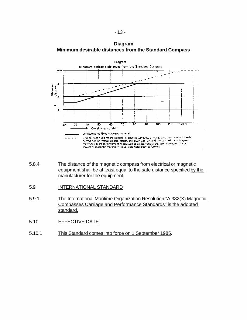
The minimum distances of the standard compass from any magnetic material which is part of the ship's structure shall be in accordance with the following diagram which gives general guidelines to indicate the minimum desirable distances from the standard compass.
The minimum desirable distances for the steering compass may be reduced to 65 per cent of the values given by the diagram provided that no distance is less than 1 m. If there is only a steering compass the minimum distances for the standard compass shall be applied as far as practicable.
- 13 -
Diagram Minimum desirable distances from the Standard Compass
5.8.4 The distance of the magnetic compass from electrical or magnetic
equipment shall be at least equal to the safe distance specified by the manufacturer for the equipment.
5.9 INTERNATIONAL STANDARD 5.9.1 The International Maritime Organization Resolution "A.382(X) Magnetic
Compasses Carriage and Performance Standards" is the adopted standard.
5.10 EFFECTIVE DATE 5.10.1 This Standard comes into force on 1 September 1985.
- 14 -
6 STANDARDS FOR GYRO-COMPASSES 6.1 INTRODUCTION 6.1.1 The gyro-compasses required by the Navigating Appliances and Equipment
Regulations shall determine the direction of the ship’s head in relation to geographic (true) north.
6.1.2 The equipment shall comply with the following minimum performance
requirements. 6.2 DEFINITIONS
For the purpose of these standards, the following definitions apply:
.1 The term “gyro-compass" comprises the complete equipment and includes all essential elements of the complete design.
.2 The “true heading” is the horizontal angle between the vertical plane
passing through the true meridian and the vertical plane passing through the ship's fore and aft datum line. It is measured from True North (000°) clockwise through 360°.
.3 The compass is said to be “settled” if any three readings taken at
intervals of thirty minutes, when the compass is on a level and stationary base, are within a band of 0.7°.
.4 The “settle point heading” is the mean value of ten readings taken at
twenty minute intervals after the compass has settled as defined in paragraph 6.2.3.
.5 The "settle point error” is the difference between settle point heading
and true heading.
.6 The other errors to which the gyro-compass is subject are taken to be the difference between the observed value and the settle point heading.
- 15 -
6.3 METHOD OF PRESENTATION 6.3.1 The compass card shall be graduated in equal intervals of one degree or a
fraction thereof. A numerical indication shall be provided at least at every ten degrees, starting from 000° clockwise through 360°. Digital type repeaters are acceptable provided they can be easily read and contain equivalent graduations.
6.4 ILLUMINATION 6.4.1 Fully adequate illumination shall be provided to enable reading of scales at
all times. Facilities for dimming shall be provided. 6.5 ACCURACY 6.5.1 Settling of equipment 6.5.1.1 When switched on in accordance with the manufacturer's instructions the
compass shall settle within six hours in latitudes of up to 60°. 6.5.1.2 The settle point error as defined in paragraph 6.2.5 at any heading and at
any latitude up to 60° shall not exceed ± 0.75 x secant latitude where heading indications of the compass shall be taken as the mean of 10 readings at 20 minute intervals, and the root mean square value of the differences between individual heading indications and the mean shall be less than 0.25° x secant latitude. The repeatability of settle point error from one run-up to another shall be within 0.25° x secant latitude.
6.5.2 Performance under operational conditions 6.5.2.1 When switched on in accordance with the manufacturer's instructions, the
compass shall settle within six hours in latitudes of up to 60° when rolling and pitching with simple harmonic motion of any period between six and fifteen seconds, a maximum angle of 5°, and a maximum horizontal acceleration of 0.22 m/s2.
6.5.2.2 The repeatability of the settle point error of the master compass shall be
within ± 1° x secant latitude under the general conditions mentioned in paragraphs 6.6.1 and 6.8 and including variations in magnetic field likely to be experienced in the ship in which it is installed.
- 16 -
6.5.2.3 In latitudes of up to 60°:
.1 the residual steady state error, after correction for speed and course influences at a speed of twenty knots, shall not exceed ± 0.25 x secant latitude;
.2 the error due to a rapid alteration of speed of twenty knots shall not
exceed ± 2°;
.3 the error due to a rapid alteration of course of 180° at a speed of twenty knots shall not exceed ± 3°;
.4 the transient and steady state errors due to the ship rolling, pitching,
and yawing, with simple harmonic motion of any period between six and fifteen seconds, maximum angle of 20°, 10°, and 5° respectively, and maximum horizontal acceleration not exceeding 1 m/s2, shall not exceed 1° x secant latitude.
6.5.2.4 In latitudes higher than 60 degrees the compass shall be capable of giving,
according to the manufacturers specifications, reliable heading information at the latitudes in which the ship is operating.
6.5.2.5 The maximum divergence in reading between the master compass and
repeaters under all operational conditions shall not exceed ± 0.5°.
Note: When the compass is used for purposes other than steering and bearing, a higher accuracy might be necessary.
To ensure that the maximum error referred to in sub-paragraph 6.5.2.3.4 is not exceeded in practice, it will be necessary to pay particular attention to the siting of the master compass.
6.6 POWER SUPPLY 6.6.1 The equipment shall be capable of operating continuously in accordance with
the requirements of these standards in the presence of such variations of the power supply as are normally expected in a ship.
6.6.2 Means shall be incorporated for the protection of the equipment from
excessive currents and voltages, transients and accidental reversal of power supply polarity.
- 17 -
6.6.3 If provision is made for operating the equipment from more than one source of electrical energy, arrangements for rapidly changing from one source of supply to other shall be incorporated.
6.7 INTERFERENCE 6.7.1 All steps shall be taken to eliminate as far as practicable the causes of, and
to suppress, electromagnetic interference between the gyro-compass and other equipment on board.
6.7.2 Mechanical noise from all units shall be so limited as not to prejudice the
hearing of sounds on which the safety of the ship might depend. 6.7.3 Each unit of the equipment shall be marked with the minimum safe distances
at which it may be mounted from a standard or a steering magnetic compass.
6.8 DURABILITY AND RESISTANCE TO EFFECTS OF CLIMATE 6.8.1 The equipment shall be capable of continuous operation under the conditions
of vibration, humidity and change of temperature likely to be experienced in the ship in which it is installed.
6.9 CONSTRUCTION AND INSTALLATION 6.9.1 The master compass and any repeaters used for taking visual bearing shall
be installed in a ship with their fore and aft datum lines parallel to the ship's fore and aft datum line to within ± 0.5°. The lubber line shall be in the same vertical plane as the centre of the card of the compass and shall be aligned accurately in the fore and aft direction.
6.9.2 Means shall be provided for correcting the errors induced by speed and
latitude. 6.9.3 An automatic alarm shall be provided to indicate a major fault in the
compass system. 6.9.4 The system shall be designed to enable heading information to be provided
to other navigational aids such as radar, radio direction-finder and automatic pilot.
6.9.5 Information shall be provided to enable competent members of a ship's staff
to operate and maintain the equipment efficiently.
- 18 -
6.9.6 The equipment shall be provided with an indication of manufacture, type
and/or number. 6.9.7 The equipment shall be so constructed and installed that it is readily
accessible for maintenance purposes. 6.9.8 The system shall be installed so that heading information will be clearly
readable by the helmsman at the main steering position. 6.10 INTERNATIONAL STANDARD 6.10.1 The International Maritime Organization Resolution “A.424(XI) Performance
Standards for Gyro Compasses” is the adopted standard. 6.11 EFFECTIVE DATE 6.11.1 This Standard comes into force on 1 September 1985.
- 19 -
7 STANDARDS FOR AUTOMATIC PILOTS 7.1 GENERAL 7.1.1 Within limits related to a vessel's manoeuvrability, the automatic pilot, in
conjunction with its source of heading information, shall enable a vessel to keep a preset course with minimum operation of the vessel's steering gear.
7.1.2 The automatic pilot equipment shall be capable of adapting to different
steering characteristics of the vessel under various weather and loading conditions, and provide reliable operation under prevailing environmental and normal operational conditions.
7.2 CHANGING OVER FROM AUTOMATIC TO MANUAL STEERING AND
VICE VERSA 7.2.1 Changing over from automatic to manual steering and vice versa shall be
possible at any rudder position and be effected by one, or at the most two manual controls, within a time lag of 3 seconds.
7.2.2 Changing over from automatic to manual steering shall be possible under
any conditions, including any failure in the automatic control system. 7.2.3 When changing over from manual to automatic steering, the automatic pilot
shall be capable of bringing the vessel to the preset course. 7.2.4 Change-over controls shall be located close to each other in the immediate
vicinity of the main steering position. 7.2.5 Adequate indication shall be provided to show which method of steering is in
operation at a particular moment. 7.3 ALARM SIGNALLING FACILITIES 7.3.1 A course monitor shall be provided which actuates an adequate "off course"
audible alarm signal after a course deviation of a preset amount. 7.3.2 The information required to actuate the course monitor shall be provided
from an independent source.
- 20 -
7.3.3 Alarm signals, both audible and visual, shall be provided in order to indicate failure or a reduction in the power supply to the automatic pilot or course monitor, which would affect the safe operation of the equipment.
7.3.4 The alarm signalling facilities shall be fitted near the steering position. 7.4 CONTROLS 7.4.1 The number of operational controls shall be minimized as far as possible and
they shall be designed to preclude inadvertent operation. 7.4.2 Unless features for automatic adjustments are incorporated in the
installation, the automatic pilot shall be provided with adequate controls for operational use to adjust effects due to weather and the ship's steering performance.
7.4.3 The automatic pilot shall be designed in such a way as to ensure altering
course to starboard by turning the course setting control clockwise. Normal alterations of course shall be possible by one adjustment only of the course setting control.
7.4.4 Except for the course setting control, the actuation of any other control shall
not significantly affect the course of the vessel. 7.4.5 Additional controls at remote positions shall comply with the provisions of
these standards. 7.5 RUDDER ANGLE LIMITATION 7.5.1 Means shall be incorporated in the equipment to enable rudder angle
limitation in the automatic mode of operation. Means shall also be available to indicate when the angle of limitation has been reached.
7.6 PERMITTED YAW 7.6.1 Means shall be incorporated to prevent unnecessary activation of the rudder
due to normal yaw motion. 7.7 INTERNATIONAL STANDARD
- 21 -
7.7.1 The International Maritime Organization Resolution "A.342(IX) Recommendation on Performance Standards for Automatic Pilots" is the adopted standard.
7.8 EFFECTIVE DATE 7.8.1 This Standard comes into force on 1 September 1985.
- 22 -
8 STANDARDS FOR RADAR 8.1 APPLICATION 8.1.1 These standards apply to all ships' radar equipment installed in compliance
with the Navigating Appliances and Equipment Regulations. 8.2 GENERAL 8.2.1 The radar equipment shall provide an indication, in relation to the ship, of the
position of other surface craft and obstructions and of buoys, shorelines and navigational marks in a manner which will assist in navigation and in avoiding collision.
8.3 ALL RADAR INSTALLATIONS 8.3.1 All radar installations shall comply with the following minimum requirements. 8.3.2 Range performance
The operational requirement under normal propagation conditions, when the radar antenna is mounted at a height of 15 metres above sea level, is that the equipment shall in the absence of clutter give a clear indication of:
.1 Coastlines
At 20 nautical miles when the ground rises to 60 metres.
At 7 nautical miles when the ground rises to 6 metres.
.2 Surface Objects
At 7 nautical miles a ship of 5,000 tons gross tonnage, whatever her aspect,
At 3 nautical miles a small vessel of 10 metres in length.
At 2 nautical miles an object such as a navigational buoy having an effective echoing area of approximately 10 square metres.
- 23 -
8.3.3 Minimum Range
The surface objects specified in paragraph 8.3.2.2 shall be clearly displayed from a minimum range of 50 metres up to a range of one nautical mile, without changing the setting of controls other than the range selector.
8.3.4 Display 8.3.4.1 The equipment shall without external magnification provide a relative plan
display in the head-up unstabilized mode with an effective diameter of not less than:
.1 180 millimetres (7 and 9 inch) on ships of 500 tons gross tonnage and
more but less than 1,600 tons gross tonnage;
.2 250 millimetres (12 inch) on ships of 1,600 tons gross tonnage and more but less than 10,000 tons gross tonnage;
.3 340 millimetres (16 inch) in the case of one display and 250
millimetres in the case of the other on ships of 10,000 tons gross tonnage and upwards.
8.3.4.2 The equipment shall provide one of the two following sets of range scales of
display:
.1 1.5, 3, 6, 12 and 24 nautical miles and one range scale of not less than 0.5 and not greater than 0.8 nautical miles; or
.2 1, 2, 4, 8, 16 and 32 nautical miles.
8.3.4.3 Additional range scales may be provided. 8.3.4.4 The range scale displayed and the distance between range rings shall be
clearly indicated at all times. 8.3.5 Range measurement 8.3.5.1 Fixed electronic range rings shall be provided for range measurements as
follows:
- 24 -
.1 where range scales are provided in accordance with paragraph 8.3.4.2.1, on the range scale of between 0.5 and 0.8 nautical miles at least two range rings shall be provided and on each of the other range scales six range rings shall be provided; or
.2 where range scales are provided in accordance with paragraph
8.3.4.2.2, four range rings shall be provided on each of the range scales.
8.3.5.2 A variable electronic range marker shall be provided with a numeric readout
of range. 8.3.5.3 The fixed range rings and the variable range marker shall enable the range of
an object to be measured with an error not exceeding 1.5 per cent of the maximum range of the scale in use, or 70 metres, whichever is the greater.
8.3.5.4 It shall be possible to vary the brilliance of the fixed range rings and the
variable range marker and to remove them completely from the display. 8.3.6 Heading Indicator 8.3.6.1 The heading of the ship shall be indicated by a line on the display with a
maximum error not greater than plus or minus 1 degree. The thickness of the displayed heading line shall not be greater than 0.5 degrees.
8.3.6.2 Provision shall be made to switch off the heading indicator by a device which
cannot be left in the “heading marker off” position. 8.3.7 Bearing Measurement 8.3.7.1 Provision shall be made to obtain quickly the bearing of any object whose
echo appears on the display. 8.3.7.2 The means provided for obtaining bearings shall enable the bearing of a
target whose echo appears at the edge of the display to be measured with an accuracy of plus or minus 1 degree or better.
8.3.8 Discrimination 8.3.8.1 The equipment shall be capable of displaying as separate indications on a
range scale of 2 nautical miles or less, two small similar targets at a range of between 50 per cent and 100 per cent of the range scale in use, and on the same azimuth, separated by not more than 50 metres in range.
- 25 -
8.3.8.2 The equipment shall be capable of displaying as separate indications two
small similar targets both situated at the same range between 50 per cent and 100 per cent of the 1.5 or 2 mile range scales, and separated by not more than 2.5 degrees in azimuth.
8.3.9 Roll or Pitch
The performance of the equipment shall be such that when the ship is rolling or pitching up to plus or minus 10 degrees the range performance requirements of paragraph 8.3.2 and 8.3.3 continue to be met.
8.3.10 Scan
The scan shall be clockwise, continuous and automatic through 360 degrees of azimuth. The scan rate shall be not less than 12 revolutions per minute. The equipment shall operate satisfactorily in relative wind speeds of up to 100 knots.
8.3.11 Azimuth stabilization 8.3.11.1 Means shall be provided to enable the display to be stabilized in azimuth by
a transmitting compass. The equipment shall be provided with a compass input to enable it to be stabilized in azimuth. The accuracy of alignment with the compass transmission shall be within 0.5 degrees with a compass rotation rate of 2 revolutions per minute.
8.3.11.2 The equipment shall operate satisfactorily in the unstabilized mode when the
compass control is inoperative. 8.3.12 Performance check
Means shall be available, while the equipment is used operationally, to determine readily a significant drop in performance relative to a calibration standard established at the time of installation, and to check that the equipment is correctly tuned in the absence of targets.
- 26 -
8.3.13 Anti-clutter devices
Suitable means shall be provided for the suppression of unwanted echoes from sea clutter, rain and other forms of precipitation, clouds and sandstorms. It shall be possible to adjust manually and continuously the anti-clutter controls. Anti-clutter controls shall be inoperative in the fully anti-clockwise positions. In addition, automatic anti-clutter controls may be provided; however, they must be capable of being switched off.
8.3.14 Operation 8.3.14.1 The equipment shall be capable of being switched on and operated from the
display position. 8.3.14.2 Operational controls shall be accessible and easy to identify and use.
Where symbols are used they should comply with the symbols for radar controls in paragraph 8.9 of this document.
8.3.14.3 After switching on from cold the equipment shall become fully operational
within 4 minutes. 8.3.14.4 A standby condition shall be provided from which the equipment can be
brought to an operational condition within 15 seconds. 8.3.15 Interference 8.3.15.1 After installation and adjustment on board, the bearing accuracy as
prescribed in these standards shall be maintained without further adjustment irrespective of the movement of the ship in the earth's magnetic field.
8.3.16 Sea or ground stabilization (true motion display) 8.3.16.1 Where sea or ground stabilization is provided the accuracy and
discrimination of the display shall be at least equivalent to that required by these standards.
8.3.16.2 The motion of the trace origin shall not, except under manual override
conditions, continue to a point beyond 75 per cent of the radius of the display. Automatic resetting may be provided.
- 27 -
8.3.17 Antenna system 8.3.17.1 The antenna system shall be installed in such a manner that the design
efficiency of the radar system is not substantially impaired. 8.3.18 Operation with radar beacons 8.3.18.1 All radars operating in the 3 centimetre band shall be capable of operating in
a horizontally polarized mode. 8.3.18.2 It shall be possible to switch off those signal processing facilities which might
prevent a radar beacon from being shown on the radar display. 8.4 MULTIPLE RADAR INSTALLATIONS 8.4.1 Where two radars are required to be carried they shall be so installed that
each radar can be operated individually and both can be operated simultaneously without being dependent upon one another. When an emergency source of electrical power is provided in accordance with the appropriate requirements of Chapter II-1 of the 1974 SOLAS Convention, both radars shall be capable of being operated from this source.
8.4.2 Where two radars are fitted, interswitching facilities may be provided to
improve the flexibility and availability of the overall radar installation. They shall be so installed that failure of either radar would not cause the supply of electrical energy to the other radar to be interrupted or adversely affected.
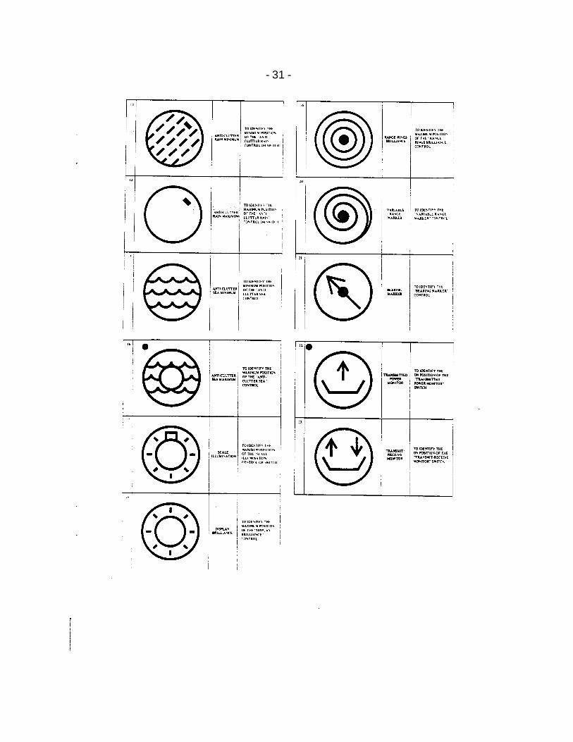
8.5 SYMBOLS FOR RADAR CONTROLS 8.5.1 LIST OF CONTROLS TO BE SYMBOLIZED 8.5.1.1 The following switches and variable controls are considered to be the
minimum required to be marked by symbols:
Radar on - standby - off switch
Aerial rotation switch
Mode of presentation switch - North up or Ship's Head up
Heading marker alignment control or switch
Range selection switch
- 28 -
Pulse length selection switch - short or long pulse
Tuning control
Gain control
Anti-clutter rain control (differentiation)
Anti-clutter sea control
Scale illumination control or switch
Display brillance control
Range rings brilliance control
Variable range marker control
Bearing marker control
Performance monitor switch - transmitted power monitor or transmit/receive monitor
8.6 CODE OF PRACTICE 8.6.1 The following code of practice should be used when marking radar sets with
recommended symbols:
.1 the maximum dimension of a symbol should not be less than 9 mm;
.2 the distance between the centres of two adjacent symbols should be not less than 1.4 times the size of the larger symbol;
.3 switch function symbols should not be linked by a line. A linked line
infers controlled action;
.4 variable control function symbols should be linked by a line, preferably an arc. The direction of increase of controlled function should be indicated;
.5 symbols should be presented with a high contrast against their
background;
- 29 -
.6 the various elements of a symbol should have a fixed ratio one to
another;
.7 multiple function of controls and switch positions may be indicated by a combined symbol;
.8 where concentric controls or switches are fitted, the outer of the
symbols should refer to the larger diameter control. 8.7 INTERNATIONAL STANDARD 8.7.1 The International maritime Organization Resolution “A.477 (XII) Performance
Standards for Radar" and Resolution "A 278 (VIII) Supplement on Standards for navigational Radar Equipment” are the adopted standards.
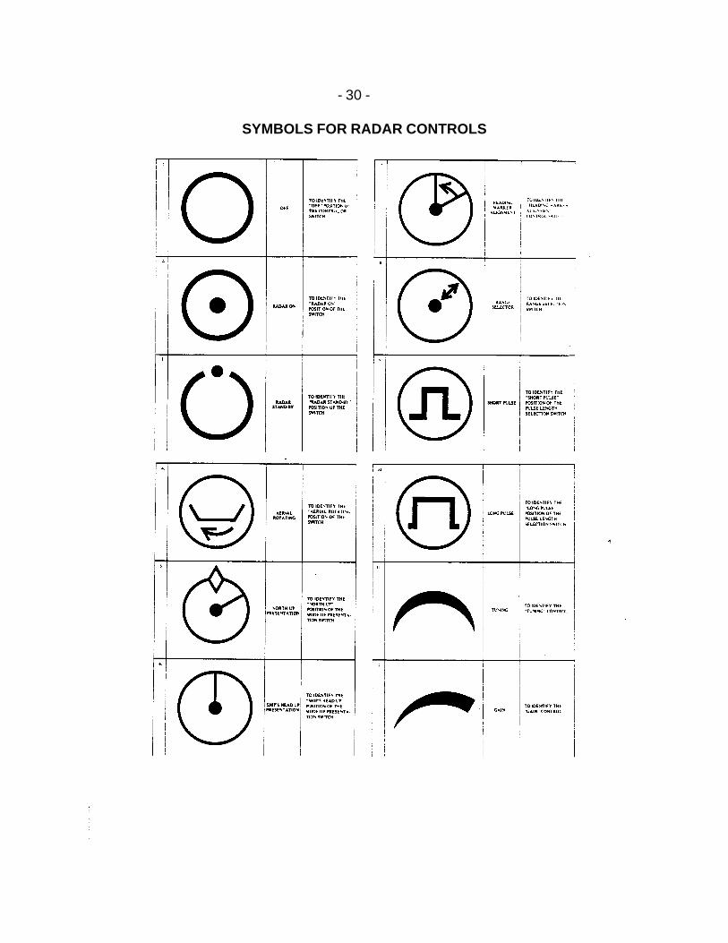
8.8 EFFECTIVE DATE 8.8.1 This standard comes into force on 1 September 1985. 8.9 SYMBOLS 8.9.1 The symbols attached hereto should be used for controls on marine
navigational radar equipment. 8.9.2 The circles shown around the following symbols are optional:
symbol 4: aerial rotating
symbol 9: short pulse
symbol 10: long pulse
symbol 17: scale illumination
symbol 22: transmitted power monitor
symbol 23: transmit/receive monitor
- 30 -
SYMBOLS FOR RADAR CONTROLS
- 31 -
- 32 -
9 STANDARDS FOR AUTOMATIC RADAR PLOTTING AIDS (ARPA) 9.1 INTRODUCTION 9.1.1 Automatic Radar Plotting Aids (ARPA) required by the Navigating
Appliances and Equipment Regulations shall, in order to improve the standard of collision avoidance at sea:
.1 reduce the work-load of observers by enabling them to automatically
obtain information so that they can perform as well with multiple targets as they can by manually plotting a single target;
.2 provide continuous, accurate and rapid situation evaluation.
9.2 DEFINITIONS 9.2.1 Definitions of terms used in these standards are given in Appendix 1. 9.3 PERFORMANCE STANDARDS 9.3.1 Detection 9.3.1.1 Where a separate facility is provided for detection of targets, other than by
the radar observer, it shall have a performance not inferior to that which could be obtained by the use of the radar display.
9.3.2 Acquisition 9.3.2.1 Target acquisition may be manual or automatic. However, there shall always
be a facility to provide for manual acquisition and cancellation. ARPA with automatic acquisition shall have a facility to suppress acquisition in certain areas. On any range scale where acquisition is suppressed over a certain area, the area of acquisition shall be indicated on the display.
9.3.2.2 Automatic or manual acquisition shall have a performance not inferior to that
which could be obtained by the user of the radar display. 9.3.3 Tracking 9.3.3.1 The ARPA shall be able to automatically track, process, simultaneously
display and continuously update the information on at least:
- 33 -
.1 20 targets, if automatic acquisition is provided, whether automatically or manually acquired;
.2 10 targets, if only manual acquisition is provided.
9.3.3.2 If automatic acquisition is provided, description of the criteria of selection of
targets for tracking shall be provided to the user. If the ARPA does not track all targets visible on the display, targets which are being tracked shall be clearly indicated on the display. The reliability of tracking shall not be less than that obtainable using manual recordings of successive target positions obtained from the radar display.
9.3.3.3 Provided the target is not subject to target swop, the ARPA shall continue to
track an acquired target which is clearly distinguishable on the display for 5 out of 10 consecutive scans.
9.3.3.4 The possibility of tracking errors, including target swop, shall be minimized
by ARPA design. A qualitative description of the effects of error sources on the automatic tracking and corresponding errors shall be provided to the user, including the effects of low signal-to-noise and low signal-to-clutter ratios caused by sea returns, rain, snow, low clouds and non-synchronous emissions.
9.3.3.5 The ARPA shall be able to display on request at least four equally time-
spaced past positions of any targets being tracked over a period of at least eight minutes.
9.3.4 Display 9.3.4.1 The display may be a separate or integral part of the ship's radar. However,
the ARPA display shall include all the data required to be provided by a radar display in accordance with the standards for radar.
9.3.4.2 The design shall be such that any malfunction of ARPA parts producing data
additional to information to be produced by the radar as required by the standards for radar shall not affect the integrity of the basic radar presentation.
9.3.4.3 The display on which ARPA information is presented shall have an effective
diameter of at least 340 mm. 9.3.4.4 The ARPA facilities shall be available on at least the following range scales:
- 34 -
.1 12 or 16 miles;
.2 3 or 4 miles. 9.3.4.5 There shall be a positive indication of the range scale in use. 9.3.4.6 The ARPA shall be capable of operating with a relative motion display with
"north-up" and either “head-up” or “course-up” azimuth stabilization. In addition, the ARPA may also provide for a true motion display. If true motion is provided, the operator shall be able to select for his display either true or relative motion. There shall be a positive indication of the display mode and orientation in use.
9.3.4.7 The course and speed information generated by the ARPA for acquired
targets shall be displayed in a vector or graphic form which clearly indicates the target’s predicted motion. In this regard:
.1 ARPA presenting predicted information in vector form only shall have
the option of both true and relative vectors;
.2 an ARPA which is capable of presenting target course and speed information in graphic form shall also, on request, provide the target's true and/or relative vector;
.3 vectors displayed shall either be time adjustable or have a fixed time-
scale;
.4 a positive indication of the time-scale of the vector in use shall be given.
9.3.4.8 The ARPA information shall not obscure radar information in such a manner
as to degrade the process of detecting targets. The display of ARPA data shall be under the control of the radar observer. It shall be possible to cancel the display of unwanted ARPA data.
9.3.4.9 Means shall be provided to adjust independently the brilliance of the ARPA
data and radar data, including complete elimination of the ARPA data.
- 35 -
9.3.4.10 The method of presentation shall ensure that the ARPA data are clearly visible in general to more than one observer in the conditions of light normally experienced on the bridge of a ship by day and by night. Screening may be provided to shade the display from sunlight but not to the extent that it will impair the observers' ability to maintain a proper lookout. Facilities to adjust the brightness shall be provided.
9.3.4.11 Provisions shall be made to obtain quickly the range and bearing of any
object which appears on the ARPA display. 9.3.4.12 When a target appears on the radar display and, in the case of automatic
acquisition, enters within the acquisition area chosen by the observer or, in the case of manual acquisition, has been acquired by the observer, the ARPA shall present in a period of not more than one minute an indication of the target's motion trend and display within three minutes the target's predicted motion in accordance with paragraphs 9.3.4.7, 9.3.6, 9.3.8.2 and 9.3.8.3.
9.3.4.13 After changing range scales on which the ARPA facilities are available or
resetting the display, full plotting information shall be displayed within a period of time not exceeding four scans.
9.3.5 Operational warnings 9.3.5.1 The ARPA shall have the capability to warn the observer with a visual and/or
audible signal of any distinguishable target which closes to a range or transits a zone chosen by the observer. The target causing the warning shall be clearly indicated on the display.
9.3.5.2 The ARPA shall have the capability to warn the observer with a visual and/or
audible signal of any tracked target which is predicted to close to within a minimum range and time chosen by the observer. The target causing the warning shall be clearly indicated on the display.
9.3.5.3 The ARPA shall clearly indicate if a tracked target is lost, other than out of
range, and the target's last tracked position shall be clearly indicated on the display.
9.3.5.4 It shall be possible to activate or de-activate the operational warnings.
- 36 -
9.3.6 Data requirements 9.3.6.1 At the request of the observer the following information shall be immediately
available from the ARPA in alphanumeric form in regard to any tracked target:
.1 present range to the target;
.2 present bearing of the target;
.3 predicted target range at the closest point of approach (CPA);
.4 predicted time to CPA (TCPA);
.5 calculated true course of target;
.6 calculated true speed of target.
9.3.7 Trial Manoeuvre 9.3.7.1 The ARPA shall be capable of simulating the effect on all tracked targets of
an own ship manoeuvre without interrupting the updating of target information. The simulation shall be initiated by the depression either of a spring-loaded switch, or of a function key, with a positive identification on the display.
9.3.8 Accuracy 9.3.8.1 The ARPA shall provide accuracies not less than those given in paragraphs
9.3.8.2 and 9.3.8.3 for the four scenarios defined in Appendix 2. With the sensor errors specified in Appendix 3, the values given relate to the best possible manual plotting performance under environmental conditions of plus and minus ten degrees of roll.
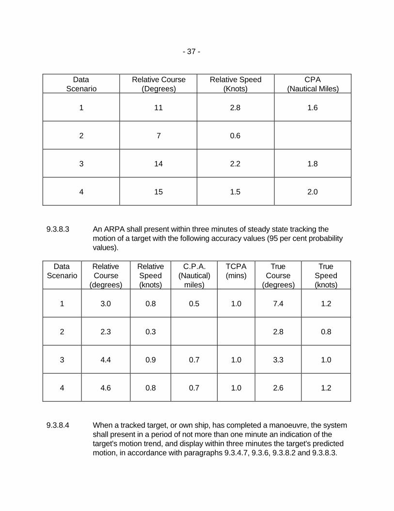
9.3.8.2 An ARPA shall present within one minute of stead state tracking the relative
motion trend of a target with the following accuracy values (95 per cent probability values).
- 37 -
Data
Scenario Relative Course
(Degrees) Relative Speed
(Knots) CPA
(Nautical Miles)
1
11
2.8
1.6
2
7
0.6
3
14
2.2
1.8
4
15
1.5
2.0
9.3.8.3 An ARPA shall present within three minutes of steady state tracking the
motion of a target with the following accuracy values (95 per cent probability values).
Data
Scenario Relative Course
(degrees)
Relative Speed (knots)
C.P.A. (Nautical)
miles)
TCPA (mins)
True Course
(degrees)
True Speed (knots)
1
3.0
0.8
0.5
1.0
7.4
1.2
2
2.3
0.3
2.8
0.8
3
4.4
0.9
0.7
1.0
3.3
1.0
4
4.6
0.8
0.7
1.0
2.6
1.2
9.3.8.4 When a tracked target, or own ship, has completed a manoeuvre, the system
shall present in a period of not more than one minute an indication of the target's motion trend, and display within three minutes the target's predicted motion, in accordance with paragraphs 9.3.4.7, 9.3.6, 9.3.8.2 and 9.3.8.3.
- 38 -
9.3.8.5 The ARPA shall be designed in such a manner that under the most
favourable conditions of own ship motion the error contribution from the ARPA shall remain insignificant compared to the errors associated with the input sensors, for the scenarios of Appendix 2.
9.3.9 Connexions with other equipment 9.3.9.1 The ARPA shall not degrade the performance of any equipment providing
sensor inputs. The connexion of the ARPA to any other equipment shall not degrade the performance of that equipment.
9.3.10 Performance tests and warnings 9.3.10.1 The ARPA shall provide suitable warnings of ARPA malfunction to enable
the observer to monitor the proper operation of the system. Additionally test programmes shall be available so that the overall performance of ARPA can be assessed periodically against a known solution.
9.3.11 Equipment used with ARPA 9.3.11.1 Log and speed indicators providing inputs to ARPA equipment shall be
capable of providing the ship's speed through the water. 9.4 INTERNATIONAL STANDARD 9.4.1 The International Maritime Organization Resolution “A.422(XI) Performance
Standards for Automatic Radar Plotting Aids (ARPA)” is the adopted standard.
9.5 EFFECTIVE DATE 9.5.1 This Standard comes into force on 1 September 1985.
- 39 -
Appendix 1
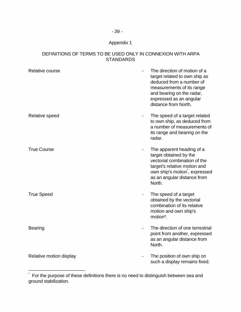
DEFINITIONS OF TERMS TO BE USED ONLY IN CONNEXION WITH ARPA STANDARDS
Relative course - The direction of motion of a
target related to own ship as deduced from a number of measurements of its range and bearing on the radar, expressed as an angular distance from North.
Relative speed - The speed of a target related
to own ship, as deduced from a number of measurements of its range and bearing on the radar.
True Course - The apparent heading of a
target obtained by the vectorial combination of the target's relative motion and own ship's motion*, expressed as an angular distance from North.
True Speed - The speed of a target
obtained by the vectorial combination of its relative motion and own ship's motion*.
Bearing - The direction of one terrestrial
point from another, expressed as an angular distance from North.
Relative motion display - The position of own ship on
such a display remains fixed.
* For the purpose of these definitions there is no need to distinguish between sea and ground stabilization.
- 40 -
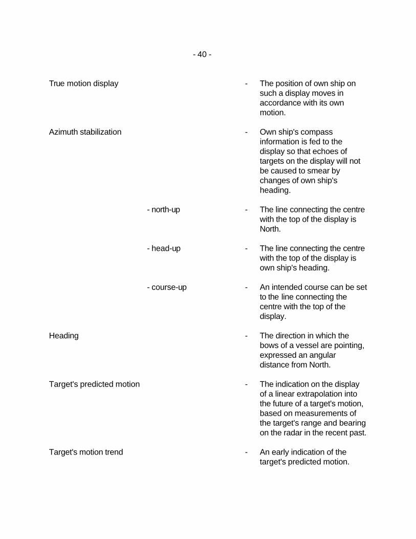
True motion display - The position of own ship on
such a display moves in accordance with its own motion.
Azimuth stabilization - Own ship's compass
information is fed to the display so that echoes of targets on the display will not be caused to smear by changes of own ship's heading.
- north-up - The line connecting the centre
with the top of the display is North.
- head-up - The line connecting the centre
with the top of the display is own ship's heading.
- course-up - An intended course can be set
to the line connecting the centre with the top of the display.
Heading - The direction in which the
bows of a vessel are pointing, expressed an angular distance from North.
Target's predicted motion - The indication on the display
of a linear extrapolation into the future of a target's motion, based on measurements of the target's range and bearing on the radar in the recent past.
Target's motion trend - An early indication of the
target's predicted motion.
- 41 -
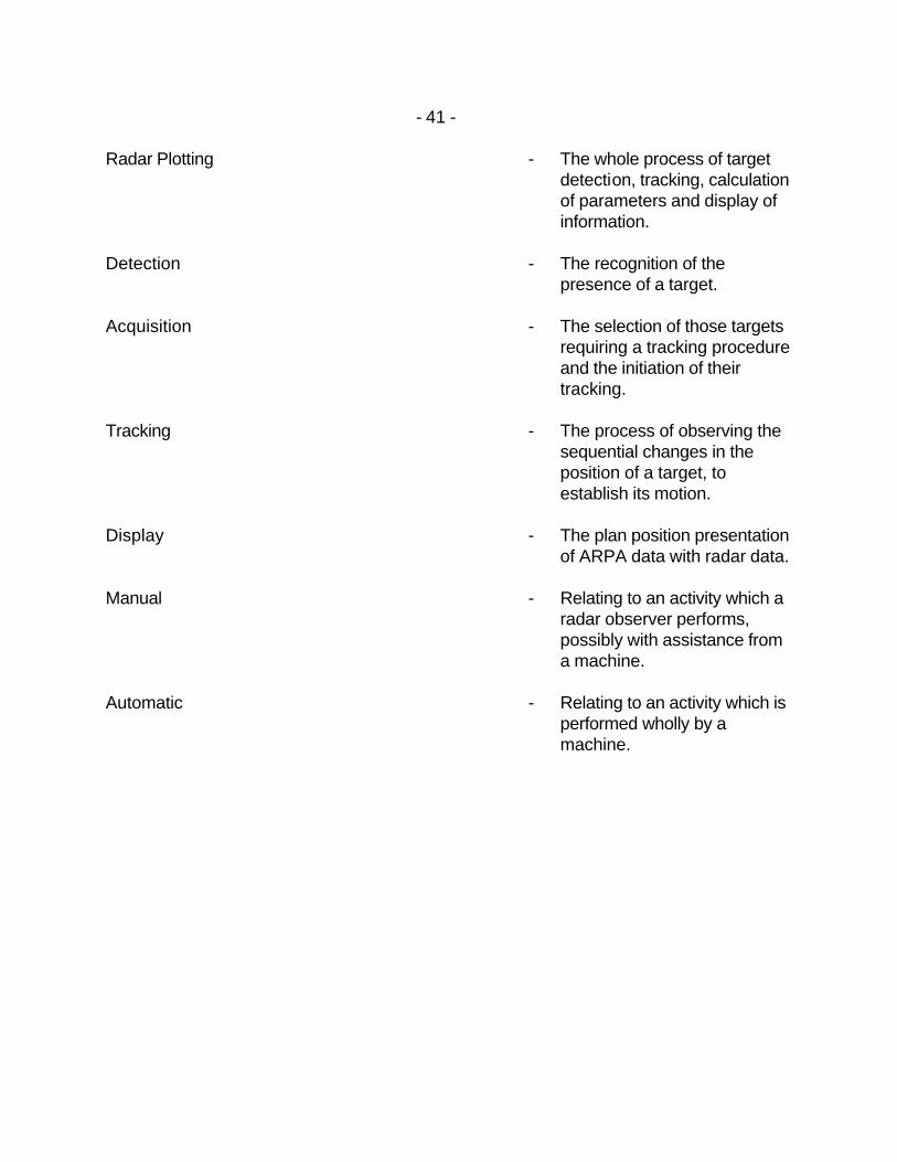
Radar Plotting - The whole process of target detection, tracking, calculation of parameters and display of information.
Detection - The recognition of the
presence of a target. Acquisition - The selection of those targets
requiring a tracking procedure and the initiation of their tracking.
Tracking - The process of observing the
sequential changes in the position of a target, to establish its motion.
Display - The plan position presentation
of ARPA data with radar data. Manual - Relating to an activity which a
radar observer performs, possibly with assistance from a machine.
Automatic - Relating to an activity which is
performed wholly by a machine.
- 42 -
Appendix 2
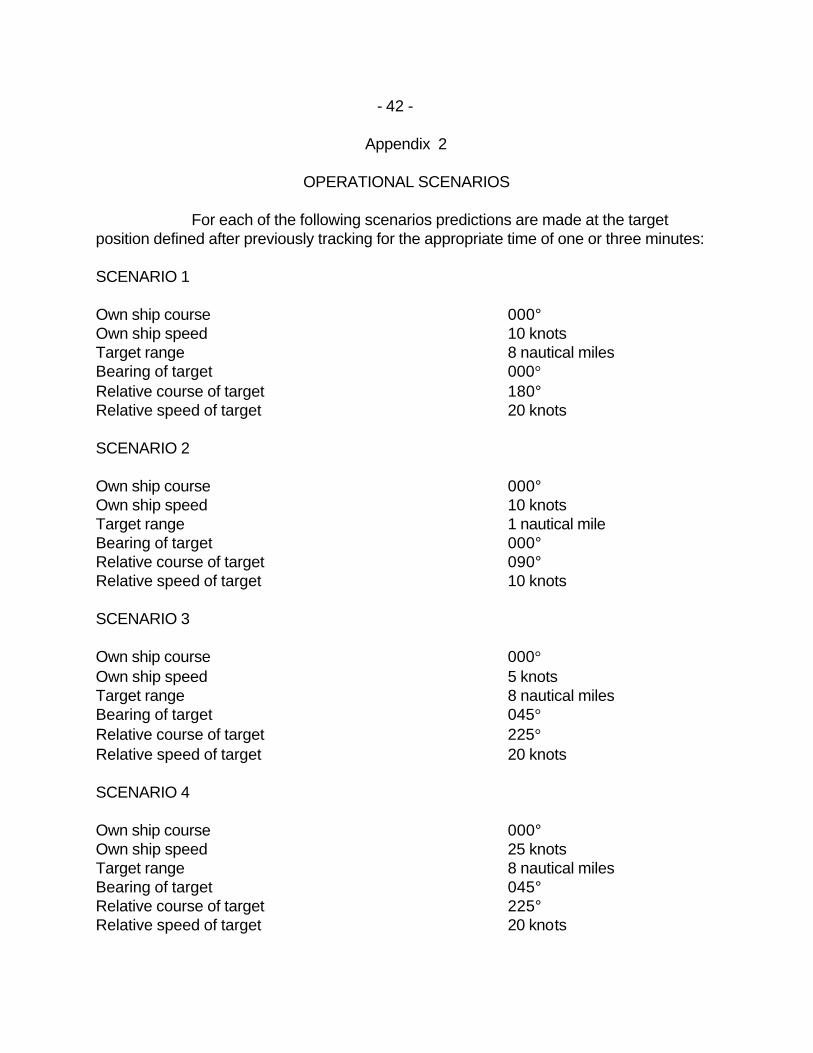
OPERATIONAL SCENARIOS
For each of the following scenarios predictions are made at the target position defined after previously tracking for the appropriate time of one or three minutes: SCENARIO 1 Own ship course 000° Own ship speed 10 knots Target range 8 nautical miles Bearing of target 000° Relative course of target 180° Relative speed of target 20 knots SCENARIO 2 Own ship course 000° Own ship speed 10 knots Target range 1 nautical mile Bearing of target 000° Relative course of target 090° Relative speed of target 10 knots SCENARIO 3 Own ship course 000° Own ship speed 5 knots Target range 8 nautical miles Bearing of target 045° Relative course of target 225° Relative speed of target 20 knots SCENARIO 4 Own ship course 000° Own ship speed 25 knots Target range 8 nautical miles Bearing of target 045° Relative course of target 225° Relative speed of target 20 knots
- 43 -
Appendix 3
SENSOR ERRORS
The accuracy figures quoted in paragraph 9.3.8 are based upon the following sensor errors and are appropriate to equipment complying with the Standards for Navigating Appliances and Equipment.
Note: σ means “standard deviation”. RADAR Target glint: (Scintillation) (for 200 m length target) Along length of target σ = 30 metres (normal distribution) Across beam of target σ = 1 metre (normal distribution) Roll-pitch bearing: The bearing error will peak in each of the four quadrants around own ship for targets on relative bearings of 045°, 135°, 225° and 315° and will be zero at relative bearings of 0°, 90°, 180° and 270°. This error has a sinusoidal variation at twice the roll frequency. For a 10° roll the mean error is
0.22° with a 0.220 peak sine wave superimposed. Beam shape: - assumed normal distribution giving bearing error with
σ = 0.05°. Pulse shape: - assumed normal distribution giving range error with σ = 20
metres. Antenna backlash: - assumed rectangular distribution giving bearing error ± 0.5°
maximum. Quantization Bearing - rectangular distribution ± 0.01° maximum. Range - rectangular distribution ± 0.01 nautical miles maximum.
- 44 -
Bearing encoder assumed to be running from a remote synchro giving bearing errors with a normal distribution σ = 0.03°. GYRO COMPASS Calibration error 0.5°. Normal distribution about this with σ = 0.12°. LOG Calibration error 0.5 knots. Normal distribution about this, 3σ = 0.2 knots.
- 45 -
10 STANDARDS FOR RADIO DIRECTION-FINDING SYSTEMS 10.1 INTRODUCTION 10.1.1 The direction-finding equipment required by the Navigating Appliances and
Equipment Regulations is to indicate both bearing and sense of radio transmissions in the frequency bands specified in paragraph 10.2.1 of these standards.
10.1.2 In addition to the provisions of the Ship Station Technical Regulations the
equipment shall comply with the following minimum performance requirements.
10.2 FREQUENCY RANGES AND CLASSES OF EMISSION 10.2.1 The equipment shall be capable of receiving signals of classes of emission
A1, A2, and A2H in the frequency range 255 to 525 kHz and A1, A2, A2H, A3 and A3H in the frequency range 2167 to 2197 kHz.
10.3 SELECTIVITY 10.3.1 The selectivity shall be such as to allow a bearing to be taken readily without
interference from other radio transmissions on frequencies more than 2 kHz from the desired signal.
10.4 SIGNAL IDENTIFICATION 10.4.1 Means of audio-monitoring shall be provided regardless of the method used
for direction-finding. 10.4.2 The equipment shall be suitable for use with headphones. A loudspeaker, if
provided, shall be capable of being rendered inoperative by simple means. 10.5 BEARING INDICATION 10.5.1 Means shall be provided to indicate the bearing of the desired transmission.
Such indication shall be capable of being easily, rapidly and precisely resolved within 0.25 degrees.
- 46 -
10.6 BEARING ACCURACY 10.6.1 The instrumental accuracy in taking bearings shall be within ± 1°. This
requirement shall be met at all frequencies in the frequency bands specified in paragraph 10.2.1 of these standards and throughout the whole 360 degrees of azimuth at field strength values between 50 µ V/m and 50 mV /m.
Note: The instrumental accuracy referred to above does not include
the operational accuracy attainable in service, which shall be determined for each installation taking into account the provisions of the Ship Station Technical Regulations. In particular the operational accuracies in the 2 MHz band shall be sufficient for homing purposes.
10.6.2 Preset facilities to correct the quandrantal error shall normally be provided for
the frequency band 255-525 kHz. 10.7 MANUAL CONTROLS AND THEIR OPERATION 10.7.1 A tuning scale or indicator shall be provided, calibrated to indicate directly
the carrier frequency of the signal to which the equipment is intended to be tuned.
10.7.2 .1 If a tuning scale is provided, at all points in its range, 1 mm shall
correspond to not more than 2.5 kHz in the frequency range 255-525 kHz.
.2 The maritime distress frequencies shall be prominently marked.
.3 Where other means of frequency indication are provided, the
resolution shall be at least 1 kHz. 10.7.3 All controls shall be of such size and location as to permit normal
adjustments to be easily performed, and shall be easy to identify and use. 10.7.4 The sense switch, if fitted, shall be of a non-locking type. 10.8 OPERATIONAL AVAILABILITY 10.8.1 The equipment shall be ready for operation within 60 seconds of switching
on.
- 47 -
10.9 POWER SUPPLY 10.9.1 If provision is made for operating the equipment from more than one source
of electrical energy arrangements for rapid change-over shall be provided. 10.9.2 Means shall be incorporated for the protection of the equipment from
excessive voltages, transients and accidental reversal of power supply polarity.
10.9.3 The equipment shall be capable of operating in accordance with the
requirements of these standards in the presence of such variations of the power supply as are normally expected in a vessel.
10.10 DURABILITY AND RESISTANCE TO EFFECTS OF CLIMATE 10.10.1 The equipment shall be capable of continuous operation under the conditions
of vibration, humidity and change of temperature likely to be experienced in the vessel in which it is installed.
10.11 SPECIAL REQUIREMENTS FOR DIFFERENT METHODS OF DIRECTION-
FINDING 10.11.1 Aural minimum method
.1 With a field strength sufficient to ensure a signal/noise ratio of at least 50 dB, a change in the setting of the bearing indicator of 5° in either direction from the position of minimum output shall cause the audio-frequency output to increase by not less than 18 dB. Similarly, a change of 90° in either direction shall cause an increase of not less than 35 dB.
.2 The equipment shall be provided with a minimum-clearing control
giving a noticeable minimum of the output at all settings.
.3 The sense shall be determined with reference to the lower output.
.4 The sense ratio in the frequency ranges 255-525 kHz and 2167-2197 kHz shall be 15 dB and 10 dB, respectively.
.5 The automatic gain control, if provided, shall be rendered inoperative
automatically when the equipment is used for bearing determination. 10.11.2 Other methods
- 48 -
.1 There shall be means of indicating that the receiver gain and signal
strength are sufficient to enable a correct bearing to be taken.
.2 With a field strength of 1 mV/m the indicated bearing shall not change by more than 1° when the receiver is detuned to a point where the indication referred to in sub-paragraph 10.11.2.1 above shows that the signal strength is just sufficient to take a bearing.
.3 For any signal of strength sufficient to give a bearing indication, there
shall be no observable change of indicated bearing when the beat frequency oscillator is switched on.
.4 Fluctuations of the indicated bearing caused by any servo mechanism
shall not exceed + 0.5° from the mean value.
.5 If, after identifying a station the bearing of which is required, it is necessary to check or alter the adjustment of any control as part of the process of direction-finding, this check and adjustment shall be capable of being made within 10 seconds.
10.12 MISCELLANEOUS 10.12.1 The equipment shall be protected from excessive voltages induced in the
aerials. 10.12.2 The equipment shall be clearly marked with the minimum safe distance at
which it may be installed from a standard or a steering magnetic compass. 10.12.3 The equipment shall be provided with an indication of manufacturer, type
and/or number. 10.12.4 .1 The equipment shall be so constructed that it is readily accessible for
maintenance purposes.
.2 Information shall be provided to enable competent members of a ship's staff to operate and maintain the equipment efficiently.
10.13 INTERNATIONAL STANDARD 10.13.1 The International Maritime Organization Resolution “A.223(VII) Performance
Standards for Radio Direction-Finding Systems" is the adopted standard.

- 49 -
10.14 EFFECTIVE DATE 10.14.1 This Standard came into force on 25 May 1980.
- 50 -
11 STANDARDS FOR ELECTRONIC POSITION FIXING EQUIPMENT 11.1 LORAN-C System 11.1.1 Application 11.1.1.1 These standards for LORAN-C, required by the Navigating Appliances and
Equipment Regulations, apply to the following types of receivers: TYPE I - Fully Automatic Acquisition, Cycle Selection, Settle, and Track
Denotes that equipment which, after the initial selection, automatically acquires the master and at least two secondaries, settles, cycle selects, tracks the signals and periodically updates the time differences.
TYPE II - Semi-Automatic Acquisition, Fully Automatic Cycle Selection, Settle,
and Track
Denotes that equipment, which automatically acquires the master signal, may require operator assistance to acquire the secondaries and then automatically settles, cycle selects, tracks the signals and periodically updates the time differences.
11.1.1.2 These Standards are based on the receiver being used with an antenna and
antenna coupler having electrical characteristics equivalent to that for which the receiver is designed.
11.1.2 ACCURACY 11.1.2.1 All Loran-C receiving equipment is required to meet a combined accuracy of
0.3 microsecond or better throughout the reference signal conditions stated in this Standard. Combined accuracy is defined as:
Combined accuracy = (MTDE)2 + (σTDE)2)1/2 11.1.2.2 Combined accuracy shall be met independently on each time difference
indicated by the receiver. 11.1.3 DYNAMIC RANGE 11.1.3.1 The receiver must meet the accuracy and lock on requirements of
paragraphs 11.1.2 and 11.1.4 throughout the range of reference signal conditions referred to in this Standard.
- 51 -
11.1.3.1 When differential signal amplitude is in excess of 60 dB, or when signal
amplitude exceeds 110 dB/1µv/m, it is permissible that the combined accuracy of the Loran-C receiving equipment be degraded. Accordingly, the receiving equipment handbook shall include the following information:
.1 Maximum signal level at which correct lock-on is attained, combined
accuracy at the signal level, and the equivalent minimum range to a station, based on an assumed signal level of:
.1 3 v/m at 1 km range, and varying inversely with distance (400
kw station)
.2 7.5 v/m at 1 km range, and varying inversely with distance (2500 kw station)
Differential signal level to be less than 60 dB.
.2 Maximum signal level at which tracking is continued after lock-on, the
combined accuracy at that signal level, and the equivalent minimum range to a station (based on the assumed signal levels above). Differential signal level to be less than 60 dB.
.3 Maximum differential signal level at which lock-on is attained, the
combined accuracy at that limit, and the equivalent minimum range to a station, based on an assumed remote signal level of 25 dB/1µv/m.
.4 Maximum differential signal level at which tracking is continued after
lock-on has been completed, the combined accuracy at that limit, and the equivalent minimum range to a station, based on an assumed remote signal level of 25 dB/1µv/m.
11.1.4 SIGNAL LOCK-ON 11.1.4.1 Maximum lock-on time shall be 7.5 minutes or less throughout reference
signal conditions. Lock-on time does not include time to tune filters. Unless all secondaries are tracked, it shall be possible to select which secondaries are to be locked-on and tracked.
11.1.4.2 When the available signal conditions degrade from the reference signal
conditions, but lock-on may still be achieved, lock-on times shall be a maximum of 20 minutes.
- 52 -
11.1.4.3 For maximum lock-on time beyond 7.5 minutes, the receiving equipment handbook shall state the maximum lock-on time for the following extensions of reference signal conditions applied individually:
.1 With a SNR between 0 and minus 10 dB
.2 With ECD's between plus 2.4 to 3.8 µs or between minus 2.4 to
3.8 µs.
.3 With a signal level between 110 and 120 dB/1µv/m or between 14 and 25 dB/1µv/m
.4 With a differential signal level between 60 and 80 dB
11.1.5 CONTINUOUS WAVE INTERFERENCE (CWI) 11.1.5.1 Paragraphs 11.1.5.1.1 to 11.1.5.1.3 below define types of CWI to which the
receiver shall be subjected. Paragraph 11.1.5.1.4 presents the actual signal and interference conditions under which the receiver shall provide specified performance. Paragraphs 11.1.5.1.5 and 11.1.5.1.6 present conditions under which the level of receiver performance shall be stated in the receiving equipment handbook. When a frequency band is referred to, the receiver shall provide stated performance when subjected to interference throughout that band unless otherwise specified. It is neither intended nor required that CWI levels in excess of 120 dB 1µv/m be addressed for paragraphs 11.1.5.1.1 through 11.1.5.1.6; such levels may be appropriate, however, under paragraph 11.1.5.1.7.
.1 Two near-synchronous near-band interfering signals, each with a SIR
of 0 dB (with respect to the lowest amplitude Loran-C signal in use). One signal shall be odd-synchronous and the other signal shall be even-synchronous.
.2 One non-synchronous near-band interfering signal with a SIR of -20
dB with respect to the lowest amplitude Loran-C signal in use.
.3 Two non-synchronous interfering signals, each with a SIR of -60 dB with respect to the lowest amplitude Loran-C signal in use. One signal shall have a frequency lower than 50 kHz and the other signal shall have a frequency higher than 200 kHz.
- 53 -
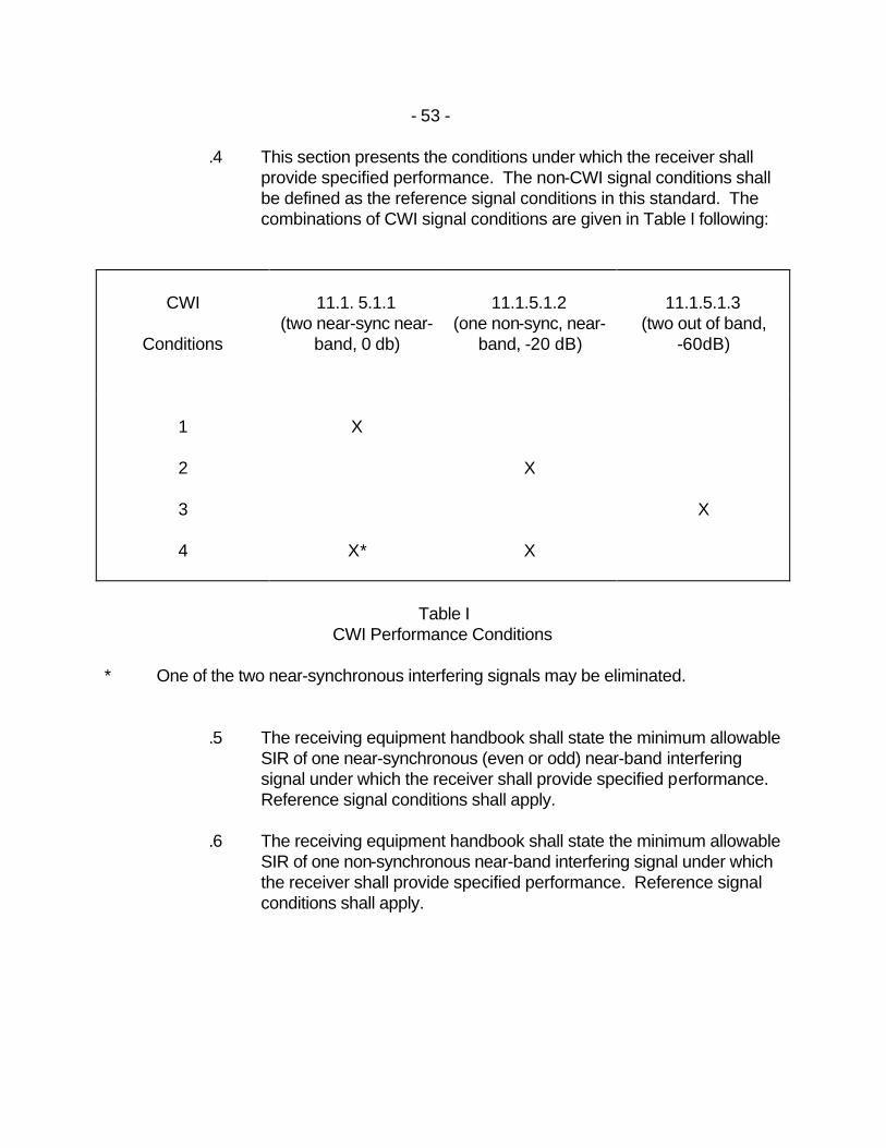
.4 This section presents the conditions under which the receiver shall provide specified performance. The non-CWI signal conditions shall be defined as the reference signal conditions in this standard. The combinations of CWI signal conditions are given in Table I following:
CWI
Conditions
11.1. 5.1.1
(two near-sync near-band, 0 db)
11.1.5.1.2
(one non-sync, near-band, -20 dB)
11.1.5.1.3
(two out of band, -60dB)
1
2
3
4
X
X*
X
X
X
Table I
CWI Performance Conditions * One of the two near-synchronous interfering signals may be eliminated.
.5 The receiving equipment handbook shall state the minimum allowable SIR of one near-synchronous (even or odd) near-band interfering signal under which the receiver shall provide specified performance. Reference signal conditions shall apply.
.6 The receiving equipment handbook shall state the minimum allowable
SIR of one non-synchronous near-band interfering signal under which the receiver shall provide specified performance. Reference signal conditions shall apply.
- 54 -
.7 The Loran-C receiver must continue to operate with specified performance in the presence of nearby transmissions from communications equipment. The receiving equipment handbook shall include antenna installation information as to minimum and preferred separation between communications transmitting antennas in the frequency range of 410 kHz to 25 MHz for typical nominal power levels, and Loran-C receiving antennas. Particular attention shall be given to the field from the 410-512 kHz main telegraph antenna.
.8 Minimum and preferred antenna separation data (with geometrical
configuration where applicable) shall be given for the following performance:
.1 specified combined accuracy and lock-on time (paragraphs
11.1.2 and 11.1.4) .
.2 the point beyond which the Loran-C receiving equipment (including the antenna system) may be permanently damaged.
11.1.6 SKYWAVE REJECTION
Skywave delays (time between corresponding points on groundwave and skywave) decrease with greater distance from the transmitter. Relative skywave signal level is defined as the ratio, in dB, between a point (e.g. the peak) on the skywave to a corresponding point on the groundwave. The receiver shall lock-on in the presence of skywave interference with delays from 32.5 µs to 45 µs and with relative skywave signal levels from 12 dB to 26 dB respectively. Nothing in this standard implies that skywave levels in excess of 94dB/1µv/m need be considered.
11.1.7 CROSS-RATE INTERFERENCE (CRI)
The receiver shall provide the required accuracy and lock-on time in the presence of CRI at a level as high as the strongest signal being used. Receiver performance shall be demonstrated by tracking simulated Southeast U.S. chain signals (7980 - SL2) in the presence of CRI at the Northeast U.S. chain rate (9960 - SS4). This is a respresentative sample of real world CRI conditions.
- 55 -
11.1.8 ALARMS 11.1.8.1 General Explanation 11.1.8.1.1 The alarms described in this section may indicate their function individually
or they may be combined into one or more general alarms. The definition of the threshold of each type of alarm condition shall be stated in the receiving equipment handbook. As a minimum, alarm conditions must be detected and displayed for all secondaries from which displayed time differences are derived.
11.1.8.1.2 The alarm actuate time is the time between the commencement of the alarm
condition and the alarm indication. The alarm reset time is the time between the termination of the alarm condition and the alarm indicator returning to normal status. In the case of a latched alarm, the alarm indicator shall remain actuated after the alarm condition is eliminated. A latched alarm shall have the capability of manual reset. If manually reset while the alarm condition still exists, the alarm shall re-energize.
11.1.8.2 Blink Alarm 11.1.8.2.1 The receiver shall detect secondary blink and energize the blink alarm within
the following time limits after the Loran-C secondary initiates blink: 11.1.8.2.1.1 Within 60 seconds when the received blinking signal has a SNR or 0 dB and
greater; 11.1.8.2.1.2 Within 90 seconds when the received blinking signal has a SNR over the
range 0 to -10 dB. 11.1.8.2.2 After the Loran-C secondary stops blink, the receiver shall detect absence of
blink and reset the blink alarm (see paragraph 11.1.8.2.3) within the following time limits:
11.1.8.2.2.1 Within 60 seconds when the received secondary signal has a SNR of 0 dB
and greater; 11.1.8.2.2.2 Within 90 seconds when the received secondary signal has a SNR over the
range 0 to -10 dB. 11.1.8.2.3 If the receiver does not provide a continuous cycle alarm (see paragraph
11.1.8.4), the blink alarm shall latch after detection of a blink condition.
- 56 -
11.1.8.2.4 It is possible that a receiver may indicate a blink condition when there is no blinking on the received signals. This is called false blink and shall not occur more frequently than one occurrence per 5 days when the SNR of the weakest secondary signal tracked is -10 dB and greater.
11.1.8.2.5 The receiver is not required to detect or display master blink or to indicate
which secondary is blinking. For a receiver which detects and displays blink on a common indicator for (one or more) secondaries whose time differences are not displayed, it shall be possible for the operator to disable blink display for those secondaries whose time differences are not displayed.
11.1.8.3 Lost Signal Alarm 11.1.8.3.1 The receiver shall detect loss of signal and energize the lost signal alarm
within 60 seconds when the affected signal had a SNR of -10 dB and greater immediately proceeding the lost signal condition.
11.1.8.3.2 The receiver shall detect restoration of the signal and reset the lost signal
alarm (see paragraphs 11.1.8.3.3) within the following time limits: 11.1.8.3.2.1 Within 15 seconds when the restored signal has a SNR of 0 dB and greater; 11.1.8.3.2.2 Within 60 seconds when the restored signal has a SNR over the range 0 to -
10 dB. 11.1.8.3.3 If the receiver does not provide a continuous cycle alarm (see paragraph
11.1.8.4), the lost signal alarm shall latch after detection of a lost signal condition.
11.1.8.3.4 It is possible that a receiver may indicate a lost signal condition when it does
not exist. This is a false alarm and shall not occur more frequently than one occurrence per 5 days when the SNR of the weakest signal tracked is -10 dB and greater.
11.1.8.3.5 The receiver is not required to display which signal has been lost. For a
receiver which displays lost signal alarm on a common indicator for (one or more) secondaries whose time differences are not displayed, it shall be possible for the operator to disable the lost signal display for those signals whose time differences are not displayed.
- 57 -
11.1.8.4 Cycle Alarm 11.1.8.4.1 If a cycle alarm is required (due to lack of latching per paragraphs 11.1.8.2.3
or 11.1.8.3.3) the receiver shall indicate any settle error. The receiving equipment handbook shall state the threshold levels, duration, and response time associated with this alarm.
11.1.8.4.2 It is possible for a receiver to indicate an alarm condition when none exists or
to fail to indicate an alarm condition when one does exist. Neither of these false indications shall occur more frequently than one occurrence per 5 days when the SNR of the weakest signal tracked is -10 dB and greater.
A cycle alarm indication during selection, acquisition, or settle operations shall not be considered an indication of receiver error.
11.1.8.4.3 For a receiver which detects and displays a cycle alarm condition on a
common indicator for (one or more) signals whose time differences are not displayed, it shall be possible for the operator to disable the cycle alarm display for those signals whose time differences are not displayed.
11.1.9 DYNAMIC TRACKING 11.1.9.1 The receiver shall provide the specified performance when mounted on a
platform performing motions as specified in this paragraph. (Motion is specified in both geographical and Loran-equivalent time-difference coordinates.)
11.1.9.1.1 At speeds up to 16 kt (3.2 microseconds/minute time-difference rate of
change) in any horizontal direction, and at accelerations up to 3 kt/minute (0.6 microsecond/minute/minute time-difference acceleration), and with additional ordinary ship motion perturbations in roll, pitch and yaw, the receiving equipment shall provide the combined accuracy and other performance parameters specified elsewhere in this Standard.
11.1.9.1.2 At speeds between 16 and 20 kt (4 micro seconds/minute time-difference
rate of change), and with ship motion and acceleration conditions as in 11.1.9.1.1, the receiving equipment shall provide combined accuracy of 0.45 microsecond or better and all other performance parameters specified elsewhere in this Standard.
- 58 -
11.1.9.1.3 In addition, the receiving equipment handbook shall state a range of speeds and accelerations throughout which the receiver meets all requirements of this standard, except that combined accuracy may be relaxed to 0.6 microsecond.
11.1.10 DISPLAYS 11.1.10.1 The receiver shall be capable of displaying, either simultaneously or
sequentially, the time differences between the master and at least two secondaries with a resolution of 0.1 µs or better. Each time difference shall update every 15 seconds or less. After lock-on, it shall not be possible to disable the indication of any alarm associated with any time difference being displayed.
11.1.11 COMBINATIONS OF CONDITIONS 11.1.11.1 In addition to the independent application of requirements cited in this
Standard, the receiver shall meet the following performance requirements throughout the range of the following conditions:
11.1.11.1.1 Conditions SNR 0 dB and greater Signal Level 25 to 110 dB/1 µv/m Differential Signal Level 0 to 60 dB ECD -2.4 µs ≤ ECD ≤ +2.4 µs Skywaves skywave delay 32.5 to 45 µs relative skywave signal level 12 dB (maximum) CWI one near-band near-synchronous signal at +10 dB SIR (minimum) one
near-band non-synchronous signal at -10 dB SIR (minimum) CRI one crossing rate signal (either master or secondary) with a level no
greater than that of the largest signal in use and with CRI selection as per paragraph 11.1.7.
Dynamic Tracking as per paragraph 11.1.9.1.1.
- 59 -
Noise Level 12 to 75 dB/1µv/m 11.1.11.1.2 Performance Reguirements Combined Accuracy 0.31 µ s or less Maximum Lock-On Time 20 minutes or less Alarms as per paragraph 11.1.8. 11.1.12 MINIMUM TEST STANDARDS 11.1.12.1 This section describes the minimum test standards a receiver must meet in
full to be considered acceptable under this Standard. 11.1.12.1.1 Effects of Tests 11.1.12.1.1.1 Unless otherwise provided, the application of the specified tests must
produce no condition which would be detrimental to the continued performance of the equipment.
11.1.12.1.1.2 If the results of a test are statistical in nature (e.g. mean, standard deviation,
etc.), all trials shall be used in the computation. If a test is designed as pass/fail at a specified minimum or maximum level or a particular level is to be determined, 90% of the trials shall be required to meet the pass criteria (for less than 10 trials, round off number to pass).
11.1.12.1.1.3 Where a test procedure evaluates the receiver master channel and not all of
the secondary channels, the test shall be repeated, with half the number of trials, so that all secondary channels shall be evaluated.
11.1.12.1.1.4 Unless otherwise specified, receivers shall meet the combined accuracy and
lock-on time required in paragraphs 11.1.2 and 11.1.4 respectively for all standards and all GRI's pursuant to this Standard for which the receiver is designed. Unless otherwise specified, the performance standards must be met throughout the full range of reference signal conditions which shall be defined as: signal levels from 25 to 110 dB/lµ4v/m, differential signal level 0 to 60 dB, ECD between plus and minus 2.4 µs, and a minimum SNR of 0 dB with the noise level within the range 12 to 75 dB/1µv/m.
- 60 -
11.1.12.1.2 Power Input Voltage 11.1.12.1.2.1 Unless otherwise specified, all tests shall be conducted with the power input
voltage adjusted to nominal design voltage ± 2%. The input voltage shall be measured at the receiver input terminals.
11.1.12.1.3 Power Input Frequency - Alternating Current 11.1.12.1.3.1 In the case of receivers designed for operation from an AC power source of
essentially constant frequency, the input frequency shall be adjusted to design frequency ± 2%.
11.1.12.1.4 Adjustment of Equipment 11.1.12.1.4.1 The circuits of the equipment shall be properly aligned and otherwise
adjusted in accordance with the manufacturer's recommended practices (including warmup time) prior to the conduct of the specified tests.
11.1.12.1.5 Test Instrument Precautions 11.1.12.1.5.1 Due precautions shall be taken to prevent the introduction of errors resulting
from the improper connection of volt meters, oscilloscopes and other test instruments to the equipment during these tests.
11.1.12.1.6 Ambient Conditions 11.1.12.1.6.1 Unless otherwise specified, all tests shall be conducted under conditions of
ambient room temperature, pressure and humidity. However, the ambient room temperature shall be not less than 10°C.
11.1.13 INTERNATIONAL STANDARD 11.1.13.1 Radio Technical Commission for Marine Services (RTCM) Paper 12-78/D0-
100 dated 20 December 1977 "Minimum Performance Standards (MPS) Marine Loran-C Receiving Equipment" section 1.2(e) TYPE I and II only, section 1.3 and sections 2.0 to 2.10 inclusive.
11.1.14 EFFECTIVE DATE 11.1.14.1 This Standard comes into force on 1 September 1985.
- 61 -
11.2 SATELLITE NAVIGATION SYSTEM (SATNAV) 11.2.1 The satellite navigation receiver must have:
.1 automatic acquisition of satellite signals after initial operator settings have been entered; and
.2 position updates derived from satellite information obtained during
each usable satellite pass. 11.2.2 INTERNATIONAL STANDARD 11.2.2.1 This Standard is based on the United States NM 1/82 Section 3. 11.2.3 EFFECTIVE DATE 11.2.3.1 This Standard comes into force on 1 September 1985. 11.3 DIFFERENTIAL OMEGA 11.3.1 INTRODUCTION 11.3.1.1 Receivers for differential Omega intended for navigational purposes on ships
with maximum speeds not exceeding 35 knots shall comply with the following minimum performance standards.
11.3.1.2 Differential Omega requires both Omega signals and differential correction
signals for correct operation. Receivers used for the reception of the differential correction signals should preferably be combined with the receivers used for reception of the Omega signals. Where separate receivers are used, care shall be taken to ensure that the installation meets the overall system performance standards.
11.3.2 PERFORMANCE STANDARDS FOR THE RECEPTION OF OMEGA
SIGNALS 11.3.2.1 Signal reception 11.3.2.1.1 The system shall provide for reception of Omega transmissions on the
frequency of 10.2 kHz. It may additionally provide for the reception of one or more of the other Omega frequencies.
- 62 -
11.3.2.1.2 The antenna shall be capable of receiving Omega signals from any direction in the horizontal plane at all times.
11.3.2.2 Positional information extraction 11.3.2.2.1 Means shall be provided for synchronizing the system to the Omega
transmission format. Automatic or manual means may be used but in any case it shall be possible to monitor the synchronization state continuously.
11.3.2.2.2 The system shall be capable of processing information from at least four
Omega stations simultaneously. 11.3.2.3 System performance 11.3.2.3.1 When a ship is stationary, the instrumental error introduced by the receiver to
the measurement of uncorrected phase difference (line of position) on any selected pair of Omega signals shall not exceed 0.02 lane widths (2 centilanes). When sailing on a constant heading at speeds up to 35 knots, instrumental error shall not exceed 0.04 lane widths (4 centilanes).
11.3.2.4 Display of positional information 11.3.2.4.1 Equipment which gives positional information in terms of lines of position
(LOPs) shall be capable of displaying at least three operator-selected LOPs either simultaneously or sequentially with the following facilities:
.1 a display of at least two whole lane digits and providing a read-out to
0.01 lane width for each pre-selected pair of stations;
.2 means for setting up initially the whole lane digit counts;
.3 identification of the selected Omega stations;
.4 where LOP information is displayed sequentially, provision shall be made for holding any one pair of stations on display for as long as required without interruption to the continuous up-dating of LOP counts. Separate visual indication that the display is in the “hold” condition shall be provided; and
.5 where provision is made for manually entering corrections in order to
display corrected LOP counts, the applied correction with its polarity sign shall be separately displayed at the same time as the corrected LOP.
- 63 -
11.3.2.4.2 An alternative method of displaying the positional information may be used,
provided that such method conforms in principle to the recommendations of paragraph 11.3.2.4.1. In the case where a latitude and longitude display is used, presentation shall be as a minimum in the form of degrees, minutes and tenths of minutes. The display shall also clearly indicate north, south, east and west. The read-out values of latitude and longitude should be based on the World Geodetic System 1972 (WGS-72).
11.3.2.4.3 Means may be provided to transform the computed position based on WGS-
72 into data compatible with the datum of the navigational chart in use. Where this facility exists, positive indication shall be provided to indicate that the facility is currently in use and means shall be provided to indicate the transformation correction.
11.3.2.4.4 When a system is designed for operation on a single Omega frequency only
it shall be provided with means of identifying lane slip sufficient to assist the re-establishment of the correct lane information.
11.3.2.5 Displays and indicators 11.3.2.5.1 The brilliance of all illumination, except for any warning light, shall be
adjustable; a common control may be used. The range of adjustment shall be such that the display of positional information is clearly readable in bright diffused daylight and at night the brightness is the minimum necessary to operate the equipment.
11.3.2.5.2 Where the figures of a digital display are built up of individual parts
(e.g. segments) then a facility shall be provided which makes it possible to check all the segments of each figure. During such checking the operation of the equipment, except for the display, shall not be interrupted.
11.3.2.6 Power supply 11.3.2.6.1 It shall be possible to supply the receiver from the usual power supplies
available on board ships: alternating current 100-115-220-230V ± 15%, 50 or 60 Hz; direct current 24-32V ± 15%.
11.3.2.6.2 The receiver shall be fitted with a built-in emergency supply which shall be
capable of being automatically substituted with no break to the normal supply described in 11.3.2.6.1 above. This emergency supply shall be capable of supplying the equipment during at least 10 minutes.
- 64 -
11.3.2.7 Warning devices 11.3.2.7.1 If the receiver is of the type which requires the operator to select the Omega
stations whose signals will be employed to generate position information, a warning device shall be provided to indicate the absence of a signal from a selected station.
11.3.2.7.2 If the receiver is of the type which automatically selects the most suitable
Omega signals from those received, a warning device shall be provided to indicate the lack of sufficient usable signals for normal equipment operation.
11.3.2.7.3 Provision may be made to indicate which Omega signals are being received
at a strength sufficient to be employed in position fixing. 11.3.2.7.4 The equipment shall be fitted with a warning device for indicating main power
supply failure which remains active until reset by the operator. 11.3.2.8 Controls 11.3.2.8.1 All controls shall be of such size as to permit normal adjustments to be made
easily. The control shall be clearly identified. 11.3.2.8.2 Where the inadvertent operation of a control could lead to failure of the
equipment or false position-fixing information, the control shall be protected from accidental operation.
11.3.2.9 Human errors 11.3.2.9.1 The number of manual calculations needed to transform the uncorrected
Omega signals into a charted position shall be kept to a minimum. Reliable automatic correction of Omega data is preferable. For navigational purposes, a reliable automatic transformation of Omega information into geographical co-ordinates is preferable. In this case due regard shall be taken of possible additional errors which may be introduced by this process.
11.3.2.10 Auxiliary equipment 11.3.2.10.1 Single frequency (10.2 kHz) receivers shall, and other receivers may, have
an output to peripheral equipment, e.g. LOP or co-ordinate recorder, or path plotter. For this output, position data should be in digital form according to the format defined in CCITT Opinion V24.
- 65 -
11.3.3 ADDITIONAL PERFORMANCE STANDARDS FOR THE RECEPTION OF DIFFERENTIAL OMEGA
11.3.3.1 Reception of signals 11.3.3.1.1 The system shall provide the reception of differential Omega corrections for
the basic frequency of 10.2 kHz. It may additionally provide for the reception of corrections for one or more of the other Omega frequencies.
11.3.3.1.2 The receiving equipment for differential Omega corrections shall be able to
receive corrections transmitted in accordance with the performance standards for differential Omega correction transmitting systems (resolution A.425(XI)) and shall indicate the Omega transmissions for which differential corrections are available. (Copies of this resolution may be obtained from Superintendent Navigation Safety, Canadian Coast Guard, Place de Ville, Ottawa, Ontario, K1A ON7)
11.3.3.1.3 Correction receivers shall operate satisfactorily when the electric field
received from the transmitting station is 10 microvolts per metre or greater, day and night, in the conditions for atmospheric noise as defined by CCIR for the band 285-415 kHz. Correction receivers shall have a selectivity, or protection devices, allowing acceptable reception of correction information when interfering signals are present. Operation shall also be possible when the interfering signal is a non modulated carrier frequency, at a level 20 dB above the wanted signal, on any frequency outside a band of ± 200 Hz centred on the nominal frequency of the correction transmitting station.
11.3.3.1.4 The antenna for the reception of differential Omega corrections may be
combined with the antenna described in 11.3.2.1.2. The antenna for the reception of differential Omega corrections (whether the same as the one described in paragraph 11.3.2.1.2 or not) shall provide satisfactory reception of correction signals in the conditions described above and from any direction in the horizontal plane.
11.3.3.2 Extraction of position data 11.3.1.2.1 Means shall be available for the synchronization of the system with the
differential Omega correction transmission format. It is possible to use automatic or manual means but, in any case, it shall be possible to monitor the state of synchronization.
11.3.3.2.2 The system shall be capable of processing information relating to at least
four Omega stations simultaneously.
- 66 -
11.3.3.3 System operation 11.3.3.3.1 Instrumental errors introduced by the correction receiving equipment shall not
be greater than those accepted for Omega receivers, according to paragraph 11.3.2.3 above.
11.3.3.4 Position information display 11.3.3.4.1 The system Omega and differential Omega may be in two forms:
.1 Separate Omega and differential Omega receivers.
.1.1 The user may only add the differential Omega corrections to the raw data from his Omega receiver before plotting his position on the chart.
.1.2 The user may enter differential Omega corrections into the Omega
receiver under the conditions described in paragraph 11.3.2.4.1.5.
.2 Combined Omega and differential Omega receivers.
.2.1 The combined receiver may separately display Omega and differential Omega data. The user may combine them as described in paragraph 11.3.3.4.1.1.
.2.2 The combined receiver may, under the control of the user,
automatically add differential Omega corrections to raw Omega data. 11.3.3.4.2 Where the differential Omega receiver gives correction information for LOPs,
it shall be able to display the corrections for at least 3 LOPs selected by the user, either simultaneously or sequentially in the following manner:
.1 Display of from 0 to 99 centilanes of correction, providing reading for
1 centilane for each station pair selected.
.2 If found necessary display combined with the display described in paragraph 11 .3.3.4.2.1 of the integer part of the correction.
.3 Identification of the selected Omega stations.
- 67 -
.4 Where LOP information is displayed sequentially, provision shall be made for holding any one pair of stations on display for as long as required without interruption to the continuous up-dating of LOP counts. Separate visual indication that the display is in the “hold” condition shall be provided.
.5 Where provision is made for manually entering corrections in order to
display corrected LOP counts, the applied correction with its polarity sign shall be separately displayed at the same time as the corrected LOP. In addition the user shall be clearly advised whether corrections are applied or not.
.6 Where means are provided for automatically entering the differential
Omega corrections, the user shall be clearly advised whether corrections are applied or not.
.7 Means shall also be provided to ensure that differential Omega
corrections can only be applied to raw Omega data. 11.3.3.4.3 Alternative methods of displaying the positional and correction information
may be used as mentioned in paragraphs 11.3.2.4.2 and 11.3.2.4.3, provided that such methods conform in principle to the recommendations of paragraphs 11.3.2.4.1 and 11.3.3.4.2.
11.3.3.4.4 Where automatic receiving systems are used:
.1 The selection of Omega stations in such a system shall be automatic. The system shall be capable of evaluating the quality of Omega signals directly received as well as that of the corrections for each Omega station. It shall establish the position information through the use of all available information from the various stations while taking account of the quality of each one. The operator shall however have the possibility to control the choice of stations manually.
.2 Position data shall be automatically obtained when a position estimated from dead-reckoning or another means has been introduced. The acceptable uncertainty on the estimated initial position is essentially related to the number of Omega frequencies that the system may directly receive on board. This acceptable uncertainty shall be clearly known by the operators.

- 68 -
.3 Even if it uses Omega corrections only on the frequency 10.2 kHz, an automatic receiver should preferably be capable of directly receiving Omega signals on the frequencies 10.2 and 13.6 kHz. It could also, although it is not essential, work with the frequencies 11.33 and 11.05 kHz.
.4 An automatic system of differential Omega should preferably be
capable of correcting the dispersion which results, at a distance from the correction transmitting station of more than 200 nautical miles, from variations of the propagation velocity of Omega waves between day and night.
.5 An automatic system shall be so designed that differential Omega
corrections can only be applied to raw Omega data.
.6 It is desirable for the system to give an indication of quality of the positional data displayed.
11.3.3.5 Displays and indicators 11.3.3.5.1 Indication and display devices shall conform with the recommendations of
paragraph 11.3.2.5. 11.3.3.6 Power supply 11.3.3.6.1 Power supply devices shall conform with the recommendations of paragraph
11.3.2.6. 11.3.3.7 Warning devices 11.3.3.7.1 The Omega and differential Omega systems shall be fitted with the warning
devices mentioned in paragraph 11.3.2.7. 11.3.3.7.2 Warning shall be given:
.1 when the correction transmitting station transmits no correction for any of the selected stations;
.2 when correction information for any of the selected stations is not
correctly received on board;
.3 when correction information has not been updated during the last period of six minutes for any of the selected stations.
- 69 -
11.3.3.7.3 A warning may be given when the 8 Hz modulation is not present. 11.3.3.7.4 For those receivers mentioned in paragraph 11.3.3.4.4, the recommendation
of paragraph 11.3.3.7.2 is replaced by an alarm if the quality of position data is unacceptable.
11.3.3.8; Controls 11.3.3.8.1 Controls shall conform with the recommendations of paragraph 11.3.2.8. 11.3.3.9 Human errors 11.3.3.9.1 The number of manual calculations needed to transform the uncorrected
Omega signals into a charted position shall be kept to a minimum. 11.3.3.9.2 Differential Omega correction shall be directly applied to raw Omega data,
excluding the usual corrections applicable to Omega use. 11.3.3.9.3 Automatic correction of raw Omega data by the corrections received from
differential Omega stations is preferable. As for Omega alone, due consideration shall be given to possible additional errors resulting from the transformation into geographical co-ordinates.
11.3.3.10 Auxiliary equipment 11.3.3.10.1 Omega and differential Omega systems may be fitted with an output for
connection with peripheral equipment such as LOP or co-ordinate recorders, or path plotters.
11.3.3.10.2 Such a facility is desirable with receivers working only with frequency
10.2 kHz and with automatic equipment. On this output position data shall be in the form of a digital message according to the format defined in CCITT Opinion V24.
11.3.3.11 INTERNATIONAL STANDARD 11.3.3.11.1 The International Maritime Organization Resolution “A.479(XII) Performance
Standards for Shipborne Receivers for use with Differential Omega" is the adopted standard.
11.3.3.12 EFFECTIVE DATE

- 70 -
11.3.3.12.1 There is no effective date for this Standard as the fitment is strictly voluntary.
- 71 -
12 STANDARDS FOR AN ECHO-SOUNDER 12.1 INTRODUCTION 12.1.1 The echo-sounding equipment required by the Navigating Appliances and
Equipment Regulations shall provide reliable information on the depth of water under a ship to aid navigation.
12.1.2 The equipment shall comply with the following minimum performance
requirements. 12.2 RANGE OF DEPTHS 12.2.1 Under normal propagation conditions the equipment shall be capable of
measuring any clearance under the transducer between 2 metres and 400 metres.
12.3 RANGE SCALES 12.3.1 The equipment shall provide a minimum of two range scales one of which,
the deep range, shall cover the whole range of depth, and the other, the shallow range, one tenth thereof.
12.3.2 The scale of display shall not be smaller than 2.5 mm per metre depth on the
shallow range scale and 0.25 mm per metre depth on the deep range scale. 12.4 METHOD OF PRESENTATION 12.4.1 The primary presentation shall be a graphical display which provides the
immediate depth and a visible record of soundings. Other forms of display may be added but these shall not affect the normal operation of the main display.
12.4.2 The record shall, on the deep range scale, show at least 15 minutes of
soundings. 12.4.3 Either by marks on the recording paper, or by other means, there shall be a
clear indication when the paper remaining is approximately 10 per cent of the length of the roll.
- 72 -
12.5 ILLUMINATION 12.5.1 Fully adequate illumination shall be provided to enable identification of
controls and facilitate reading of record and scales at all times. Facilities for dimming shall be provided.
12.6 PULSE REPETITION RATE 12.6.1 The pulse repetition rate shall be not slower than 12 pulses per minute. 12.7 ACCURACY OF MEASUREMENT 12.7.1 Based on a sound speed in water of 1500 metres per second, the allowable
tolerance on the indicated depth shall be:
either
± 1 metre on the shallow range scale
± 5 metres on the deep range scale
or
± 5 per cent of the indicated depth, whichever is the greater 12.8 ROLL AND PITCH 12.8.1 The performance of the equipment shall be such that it will meet the
requirements of these standards when the ship is rolling ± 10° and/or pitching ± 5°.
12.9 POWER SUPPLY 12.9.1 The equipment shall be capable of operating in accordance with the
requirements of these standards in the presence of such variations of the power supply as are normally expected in a vessel.
12.9.2 Means shall be incorporated for the protection of the equipment from
excessive currents and voltages, transients and accidental reversal of power supply polarity.
- 73 -
12.9.3 If provision is made for operating the equipment from more than one source of electrical energy, arrangements for rapidly changing from one source of supply to the other shall be incorporated.
12.10 INTERFERENCE 12.10.1 All reasonable and practicable steps shall be taken to eliminate the causes
of, and to suppress, radio interference to other equipment on board. 12.10.2 Mechanical noise from all units shall be so limited as not to prejudice the
hearing of sounds on which the safety of the ship might depend. 12.10.3 Each unit of the equipment shall be marked with the minimum safe distances
at which it may be mounted from a standard or a steering magnetic compass.
12.11 DURABILITY AND RESISTANCE TO EFFECTS OF CLIMATE 12.11.1 The equipment shall be capable of continuous operation under the conditions
of sea states, vibration, humidity and change of temperature likely to be experienced in the vessel in which it is installed.
12.12 MISCELLANEOUS 12.12.1 The equipment shall be provided with an indication of manufacturer, type
and/or number. 12.12.2 .1 The equipment shall be so constructed that it is readily accessible
for maintenance purposes.
.2 Information shall be provided to enable competent members of a ship's staff to operate and maintain the equipment efficiently.
12.13 INTERNATIONAL STANDARD 12.13.1 The International Maritime Organization Resolution "A.224(VII) Performance
Standards for Echo-Sounding Equipment” is the adopted standard. 12.14 EFFECTIVE DATE 12.14.1 This Standard comes into force on 1 September 1985.
- 74 -
13 STANDARDS FOR DEVICES TO INDICATE SPEED AND DISTANCE 13.1 INTRODUCTION 13.1.1 Devices to indicate speed and distance required by the Navigating
Appliances and Equipment Regulations are intended for general navigational use to provide information on the distance run and the forward speed of the ship, through the water or over the ground. The equipment shall function at forward speeds up to the maximum speed of the ship and in water of depth greater than 3 metres beneath the keel.
13.2 METHODS OF PRESENTATION 13.2.1 Speed information may be presented in either analogue or digital form.
Where a digital display is used, its incremental steps shall not exceed 0.1 knots. Analogue displays shall be graduated at least every 0.5 knots and be marked with figures at least every 5 knots. If the display can present the speed of the ship in both forward and reverse directions, the direction of movement shall be indicated unambiguously.
13.2.2 Distance run information shall be presented in digital form. The display shall
cover the range from 0 to less than 9999.9 nautical miles and the incremental steps shall not exceed 0.1 nautical mile. Where practicable, means shall be provided for resetting a readout to zero.
13.2.3 The display shall be easily readable by day and by night. 13.2.4 Means shall be provided for feeding distance run information to other
equipment fitted on board. The information shall be in the form of one contact closure or the equivalent for every 0.005 nautical miles run.
13.2.5 If equipment is capable of being operated in either the "speed through the
water” or “speed over the ground" modes, mode selection and mode indication shall be provided.
13.3 ACCURACY OF MEASUREMENT 13.3.1 Errors in the indicated speed, when the ship is operating free from shallow
water effect, and from the effects of wind, current and tide shall not exceed 5 per cent of the speed of the ship, or 0.5 knots, whichever is the greater.
- 75 -
13.3.2 Errors in the indicated distance run, when the ship is operating free from shallow water effect, and from the effects of wind, current and tide shall not exceed 5 percent of the distance run by the ship in one hour or 0.5 nautical miles in each hour, whichever is the greater.
13.3.3 If the accuracy of devices to indicate speed and distance run can be affected
by certain conditions (e.g. sea state and its effects, water temperature, salinity, sound velocity in water, the depth of water under the keel, heel and trim of ship), details of possible effects shall be included in the equipment handbook.
13.4 ROLL AND PITCH 13.4.1 The performance of the equipment shall be such that it will meet the
requirements of these standards when the ship is rolling up to plus or minus 10 degrees and pitching up to plus or minus 5 degrees.
13.5 CONSTRUCTION AND INSTALLATION 13.5.1 The system shall be so designed that neither the method of attachment of
parts of the equipment to the ship nor damage occurring to any part of the equipment which penetrates the hull could result in the ingress of water to the ship.
13.5.2 Where any part of the system is designed to extend from and retract into the
hull of the ship, the design shall ensure that it can be extended, operated normally and retracted at all speeds up to the maximum speed of the ship. Its extended and retracted positions shall be clearly indicated at the display position.
13.6 INTERNATIONAL STANDARD 13.6.1 The International Maritime Organization Resolution “A.478(XII) Performance
Standards for Devices to Indicate Speed and Distance" is the adopted standard.
13.7 EFFECTIVE DATE 13.7.1 This Standard comes into force on 1 September 1985.
- 76 -
14 STANDARDS FOR RATE-OF-TURN INDICATORS 14.1 OPERATIONAL STANDARDS 14.1.1 The Rate-of-Turn Indicator (ROTI) shall be capable of indicating rates of turn
to starboard and to port of the ship to which it is fitted. 14.1.2 The ROTI may be self-contained; alternatively it may form part of, or derive
information from, any other appropriate equipment. 14.2 INDICATION 14.2.1 The indication required shall be provided by a centre-zero analogue type
indicator (preferably circular). Where a circular scale indicator is used, the zero shall be uppermost.
14.2.2 A turn of ship to port shall be indicated on the left of the zero point and a
starboard turn to the right of the zero point. If the actual rate of turn exceeds full scale deflection, this shall be clearly indicated on the display.
14.2.3 In addition, an alphanumeric display may be provided. Positive indication of
port and starboard shall be provided on such displays. 14.2.4 The length of scale in either direction from zero shall not be less than
120 mm. The sensitivity of the system shall ensure that a change in the rate of turn of one degree per minute is represented by a distance of not less than 4 mm on its scale.
14.3 RANGE SCALES 14.3.1 A linear range scale of not less than ± 30 degrees per minute shall be
provided. This scale shall be marked in intervals of one degree per minute on both sides of zero. The scale shall be marked with figures every 10 degrees per minute. Every 10 degree mark shall be significantly longer than the 5 degree mark which in turn shall be significantly longer than the one degree mark. The marks and figures shall preferably be red or a light colour on a dark background.
14.3.2 Additional linear range scales may be provided. 14.3.3 Damping of the ROTI shall be provided with a time constant which may be
varied during operation in the range zero to at least 10 seconds.
- 77 -
14.4 ACCURACY 14.4.1 The indicated rate of turn shall not deviate from the actual rate of turn of the
ship by more than 0.5 degrees per minute plus 5 per cent of the indicated rate of turn of the ship. These values include the influence of earth rate.
14.4.2 Periodic rolling motion of the ship with an amplitude of ± 5 degrees and
period of up to 25 seconds and periodic pitching motion with an amplitude of ± 1 degree and period of up to 20 seconds shall not change the mean value of the indicated rate of turn by more than 0.5 degrees per minute.
14.4.3 The ROTI shall meet these accuracy requirements at all ship speeds up to 10
knots. 14.5 OPERATION 14.5.1 The ROTI shall be ready for operation and comply with these standards
within 4 minutes of being switched on. 14.5.2 The design shall be such that whether operating or not, the ROTI will not
degrade the performance of any other equipment to which it is connected. 14.5.3 The ROTI shall include a means of enabling the operator to verify that it is
operating. 14.6 INTERNATIONAL 14.6.1 The International Maritime Organization Resolution A.526(XIII) “Operational
Standards for Rate-of-Turn Indicators" is the adopted standard. 14.7 EFFECTIVE DATE 14.7.1 This Standard comes into force on 1 September 1985.
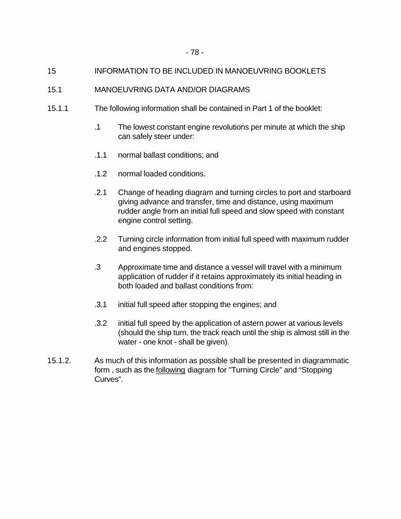
- 78 -
15 INFORMATION TO BE INCLUDED IN MANOEUVRING BOOKLETS 15.1 MANOEUVRING DATA AND/OR DIAGRAMS 15.1.1 The following information shall be contained in Part 1 of the booklet:
.1 The lowest constant engine revolutions per minute at which the ship can safely steer under:
.1.1 normal ballast conditions; and
.1.2 normal loaded conditions.
.2.1 Change of heading diagram and turning circles to port and starboard
giving advance and transfer, time and distance, using maximum rudder angle from an initial full speed and slow speed with constant engine control setting.
.2.2 Turning circle information from initial full speed with maximum rudder
and engines stopped.
.3 Approximate time and distance a vessel will travel with a minimum application of rudder if it retains approximately its initial heading in both loaded and ballast conditions from:
.3.1 initial full speed after stopping the engines; and
.3.2 initial full speed by the application of astern power at various levels
(should the ship turn, the track reach until the ship is almost still in the water - one knot - shall be given).
15.1.2. As much of this information as possible shall be presented in diagrammatic
form , such as the following diagram for "Turning Circle” and “Stopping Curves”.
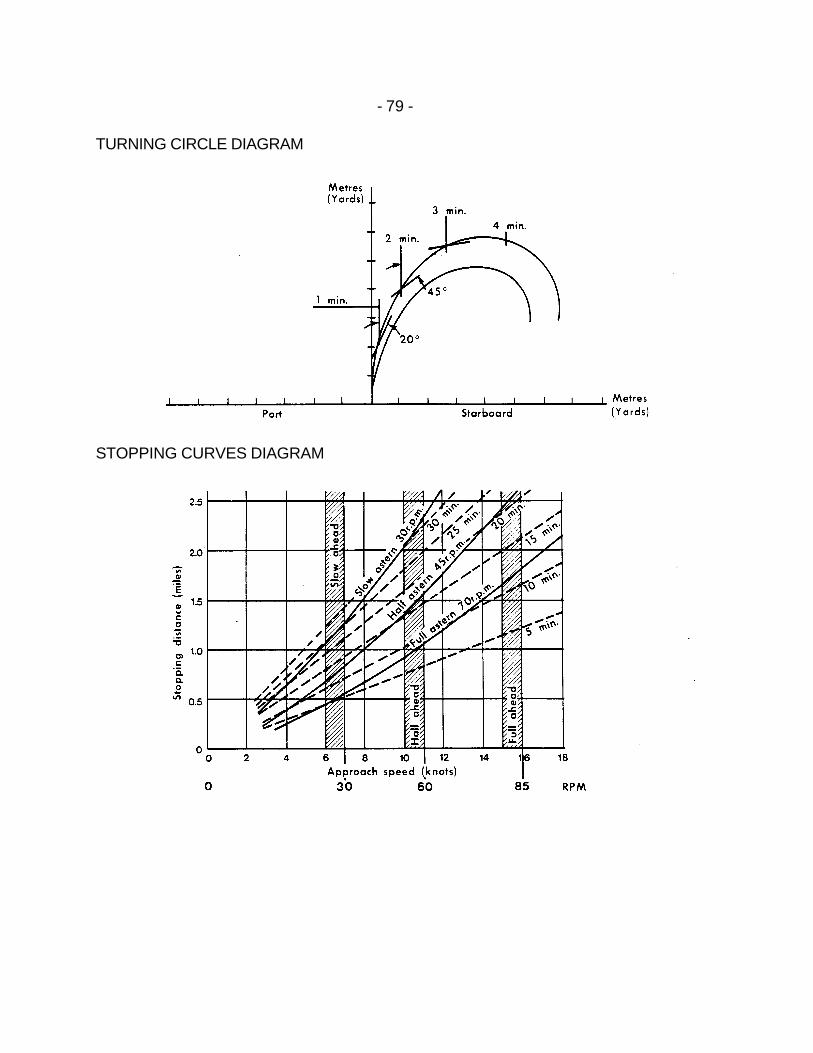
- 79 -
TURNING CIRCLE DIAGRAM
STOPPING CURVES DIAGRAM
- 80 -
15.1.3 It is recognized that all the necessary information may not be available at the time of the original trials and some of the data may have to be obtained after the ship is in service. However, the basic information shall be completed as soon as practicable. Furthermore, the booklet shall be in such a form that additional data for each manoeuvre could be added and that shipmasters be encouraged to add to this basic information as they gain experience in the handling of the vessel in conditions not covered by the original data.
15.1.4 Copies of the appropriate diagrams shall be posted on the bridge. 15.1.5 All data provided shall be for calm weather, no current and deep-water
conditions with clean hull. These facts shall be clearly noted on the data displayed with a warning that the vessel's response may significantly change under different conditions, including shallow water.
15.2 SUPPLEMENTARY INFORMATION 15.2.1 The attention of masters is drawn to the following points which shall be
considered in relation to the safe handling of the ship:
.1 Squat. The decrease in clearance under the keel when a vessel is under way in shallow water is known as squat, and varies with speed. A vessel which will in certain circumstances squat several feet can effectively reduce this by a substantial reduction in speed.
.2 The extent of “blind zone” forward created by the forward part of the
vessel may be inhibiting and its extent shall be determined in both loaded and ballast conditions.
.3 Consideration shall be given to the effective increase in draught due
to the ship motion in a seaway.
.4 It shall be noted that where practicable the quickest method of reducing headway is to turn under the influence of full rudder, with or without the use of engine astern power.
15.3 INTERNATIONAL STANDARD 15.3.1 The International Maritime Organization Resolution "A.209(VII)
Recommendation on Information to be included in the Manoeuvring Booklets" is the adopted standard.

- 81 -
15.4 EFFECTIVE DATE 15.4.1 This Standard comes into force on 1 September 1985.