Embed Size (px)
Citation preview
Standpipe Synchronous Condenser and South-Central Wyoming Voltage
Coordination
Presentation to WECC TSS
May 8, 2015
© 2
011
PA
CIF
ICO
RP
| P
AG
E 2
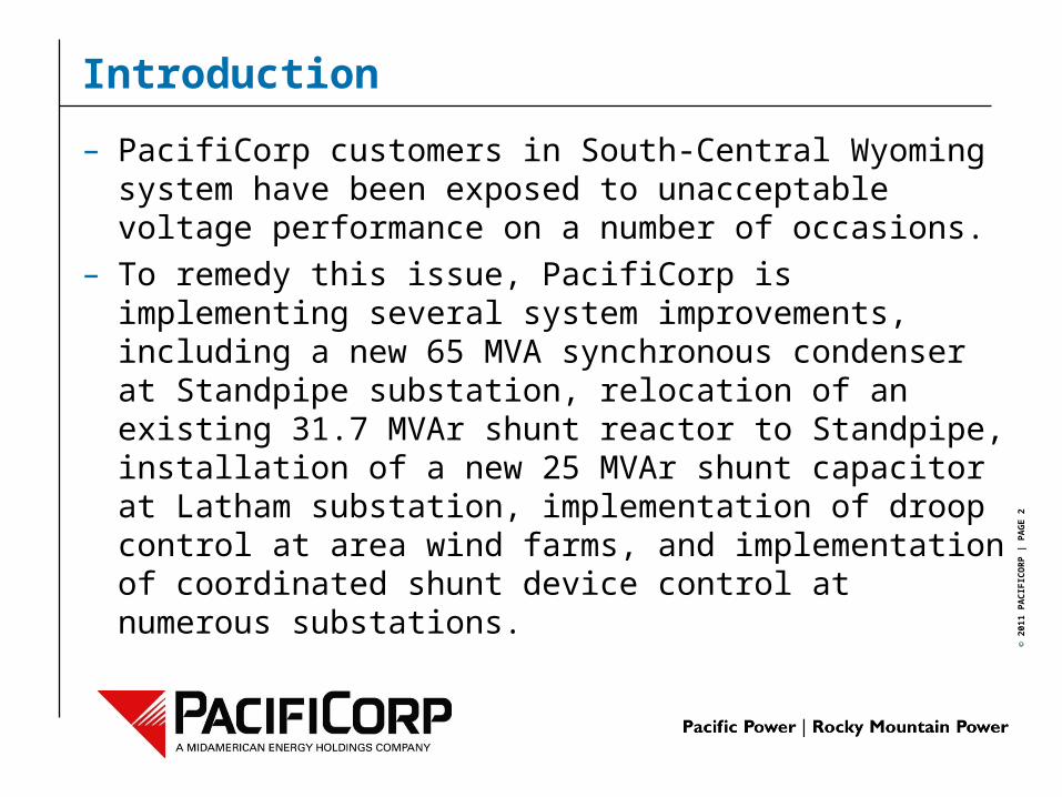
Introduction
– PacifiCorp customers in South-Central Wyoming system have been exposed to unacceptable voltage performance on a number of occasions.
– To remedy this issue, PacifiCorp is implementing several system improvements, including a new 65 MVA synchronous condenser at Standpipe substation, relocation of an existing 31.7 MVAr shunt reactor to Standpipe, installation of a new 25 MVAr shunt capacitor at Latham substation, implementation of droop control at area wind farms, and implementation of coordinated shunt device control at numerous substations.
© 2
011
PA
CIF
ICO
RP
| P
AG
E 3
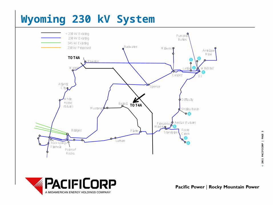
Wyoming 230 kV System
MidwestAntelope
Mine
Pumpkin Buttes
Badwater
Aeolus (Future)
Latigo
DJ
Windstar
TOT4A
TOT4AShirley Basin
Casper
Miners
Difficulty
Spence
Latham
Platte Foote Creek
Bairoil
Mustang
Point of Rocks
Atlantic City
White Horse (future)
Bridger
Rock Springs
Firehole
Wyopo
Riverton
Standpipe
< 230 kV Existing
230 kV Proposed
230 kV Existing
345 kV Existing
Freezeout
© 2
011
PA
CIF
ICO
RP
| P
AG
E 4
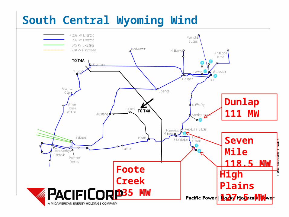
South Central Wyoming Wind
MidwestAntelope
Mine
Pumpkin Buttes
Badwater
Aeolus (Future)
Latigo
DJ
Windstar
TOT4A
TOT4AShirley Basin
Casper
Miners
Difficulty
Spence
Latham
Platte Foote Creek
Bairoil
Mustang
Point of Rocks
Atlantic City
White Horse (future)
Bridger
Rock Springs
Firehole
Wyopo
Riverton
Standpipe
< 230 kV Existing
230 kV Proposed
230 kV Existing
345 kV Existing
Freezeout
High Plains127.5 MW
Foote Creek135 MW
Seven Mile118.5 MW
Dunlap111 MW
© 2
011
PA
CIF
ICO
RP
| P
AG
E 5
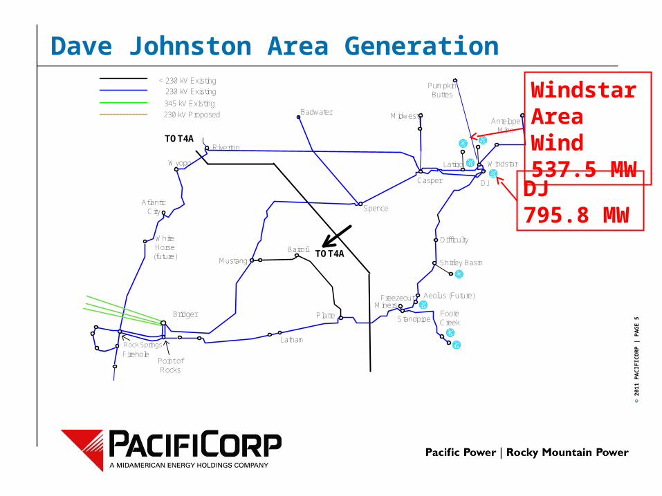
Dave Johnston Area Generation
MidwestAntelope
Mine
Pumpkin Buttes
Badwater
Aeolus (Future)
Latigo
DJ
Windstar
TOT4A
TOT4AShirley Basin
Casper
Miners
Difficulty
Spence
Latham
Platte Foote Creek
Bairoil
Mustang
Point of Rocks
Atlantic City
White Horse (future)
Bridger
Rock Springs
Firehole
Wyopo
Riverton
Standpipe
< 230 kV Existing
230 kV Proposed
230 kV Existing
345 kV Existing
Freezeout
DJ795.8 MW
Windstar Area Wind537.5 MW

© 2
011
PA
CIF
ICO
RP
| P
AG
E 6
Voltage Performance
– Wind generation interconnected on the DJ to Point of Rocks 230 kV line tends to flow west (away from DJ).
– The Platte to Standpipe 230 kV line acts as a funnel for area generation, and sees the highest line flows in the region.
– Flow above 475 MVA is possible under maximum wind conditions.
– Flow on this line segment is directly correlated with wind generation output from Foote Creek, High Plains, Seven Mile, and Dunlap, and line flow can vary significantly with wind generation output.

© 2
011
PA
CIF
ICO
RP
| P
AG
E 7
Voltage Performance (ctd.)
– As generation output in the area varies, line load fluctuates above and below the surge impedance load of the line, resulting in large, relatively slow voltage swings.
© 2
011
PA
CIF
ICO
RP
| P
AG
E 8
Voltage Performance (ctd.)
– THE PERFECT STORM:
– High voltages are seen in the area when the DJ to Difficulty line is open in conjunction with low wind conditions.
– The DJ to Difficulty outage results in an approximately 200 mile-long, radial, lightly-loaded 230 kV line.
– During low wind conditions, area wind farms have little or no regulating capability.
– With the tie to DJ open, there is very little short-circuit MVA.

© 2
011
PA
CIF
ICO
RP
| P
AG
E 9
Standpipe Project
– To remedy voltage issues in the region, PacifiCorp is implementing several system improvements under the Standpipe project, including the following: Installation of a new +65 / -40 MVAr synchronous condenser at
Standpipe substation. Relocation of an existing 31.7 MVAr shunt reactor to Standpipe. Installation of a new 25 MVAr shunt capacitor at Latham substation Implementation of droop control at area wind farms Implementation of coordinated shunt device control at Latham, Platte,
Miners, and Standpipe. Decommissioning of the Foote Creek DVAR and implementation of
power factor control of the shunt caps at Foote Creek.

© 2
011
PA
CIF
ICO
RP
| P
AG
E 1
0
Standpipe Synchronous Condenser
– Several dynamic reactive device technologies were investigated for Standpipe, including Static VAr Compensators (SVC), Voltage-Sourced Converters (STATCOM), and Synchronous Condensers.
– The synchronous condenser was selected based largely on technical criteria The Wyoming 230 kV system is heavily shunt compensated, and
voltage instability was a concern with an SVC installation. System inertia relative to transfer levels (stiffness factor) in the region
is very low. To date, STATCOM installations on the PacifiCorp system have not
proven reliable, and difficulties were encountered procuring a STATCOM.
The voltage swings in the region tend to be relatively slow, therefore speed of the device was not a significant factor.
© 2
011
PA
CIF
ICO
RP
| P
AG
E 1
1
Standpipe Synchronous Condenser
– There are several advantages of a synchronous condenser for this application. The condenser is a rotating machine, and adds inertia to the system. Control of the device is relatively simple and is not impacted by
system configuration or future system upgrades. Linear output characteristic. Very few power quality issues.
• Voltage drop from starting was a concern; however a pony motor will be utilized to start the device.
Coordination with local area wind farms can be managed with droop settings.
– There are also disadvantages associated with a condenser Losses Maintenance requirements
© 2
011
PA
CIF
ICO
RP
| P
AG
E 1
2
Standpipe Condenser Dynamic Expansion
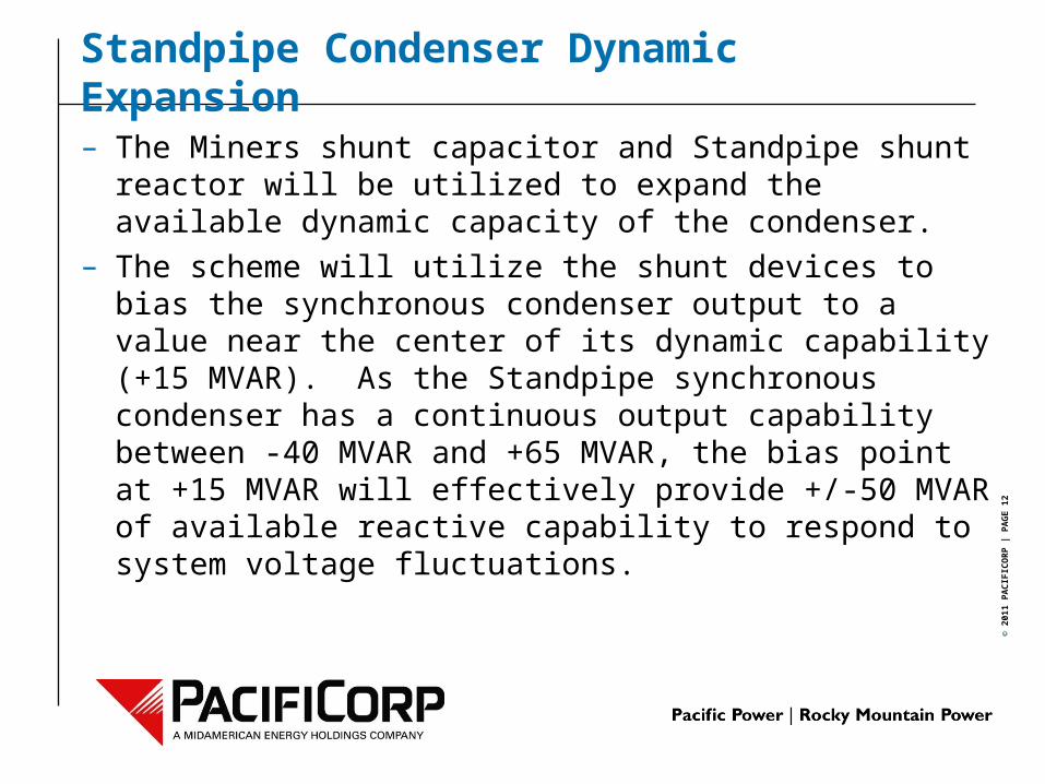
– The Miners shunt capacitor and Standpipe shunt reactor will be utilized to expand the available dynamic capacity of the condenser.
– The scheme will utilize the shunt devices to bias the synchronous condenser output to a value near the center of its dynamic capability (+15 MVAR). As the Standpipe synchronous condenser has a continuous output capability between -40 MVAR and +65 MVAR, the bias point at +15 MVAR will effectively provide +/-50 MVAR of available reactive capability to respond to system voltage fluctuations.
© 2
011
PA
CIF
ICO
RP
| P
AG
E 1
3
Standpipe Condenser Dynamic Expansion
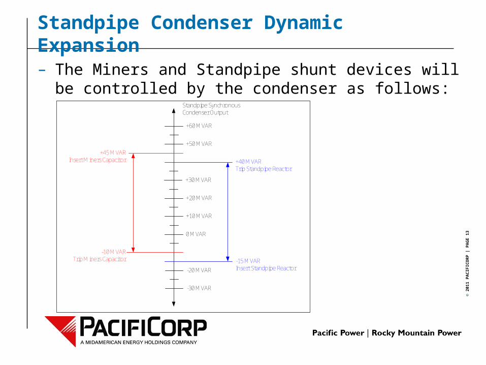
– The Miners and Standpipe shunt devices will be controlled by the condenser as follows:
0 MVAR
+10 MVAR
+20 MVAR
+30 MVAR
+40 MVARTrip Standpipe Reactor
+50 MVAR
+60 MVAR
-30 MVAR
-20 MVAR
+45 MVARInsert Miners Capacitor
-15 MVAR Insert Standpipe Reactor
-10 MVARTrip Miners Capacitor
Standpipe Synchronous Condenser Output

© 2
011
PA
CIF
ICO
RP
| P
AG
E 1
4
Wyoming Shunt Device Coordination
Latham1x25 MVAr Cap
© 2
011
PA
CIF
ICO
RP
| P
AG
E 1
5
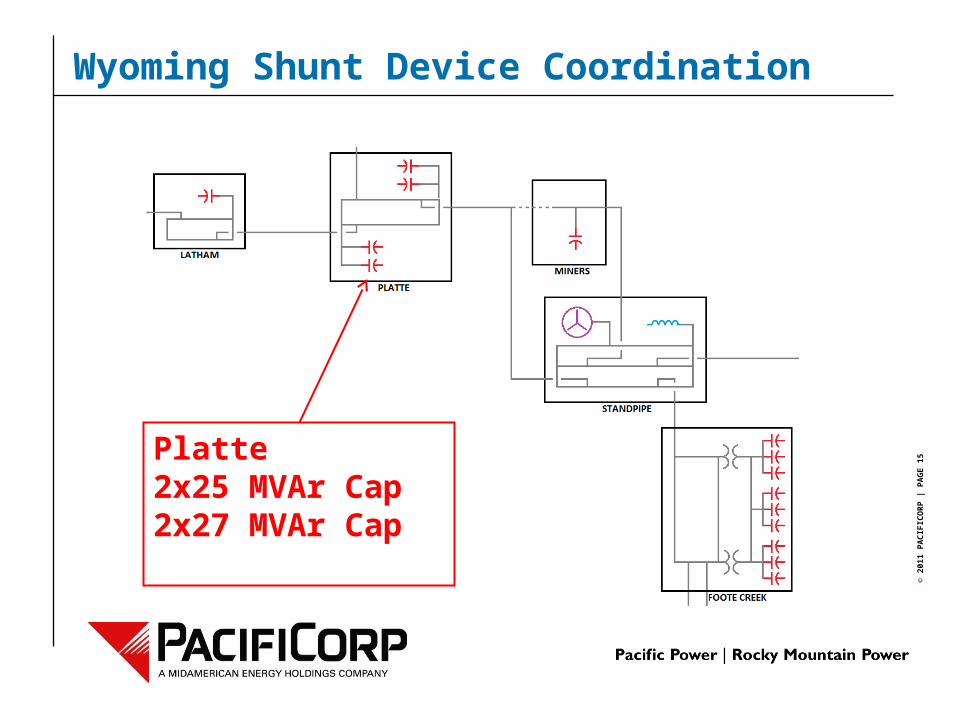
Wyoming Shunt Device Coordination
Platte2x25 MVAr Cap2x27 MVAr Cap
© 2
011
PA
CIF
ICO
RP
| P
AG
E 1
6
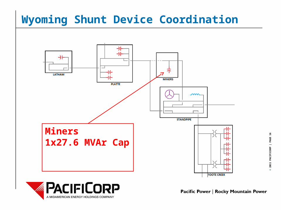
Wyoming Shunt Device Coordination
Miners1x27.6 MVAr Cap
© 2
011
PA
CIF
ICO
RP
| P
AG
E 1
7
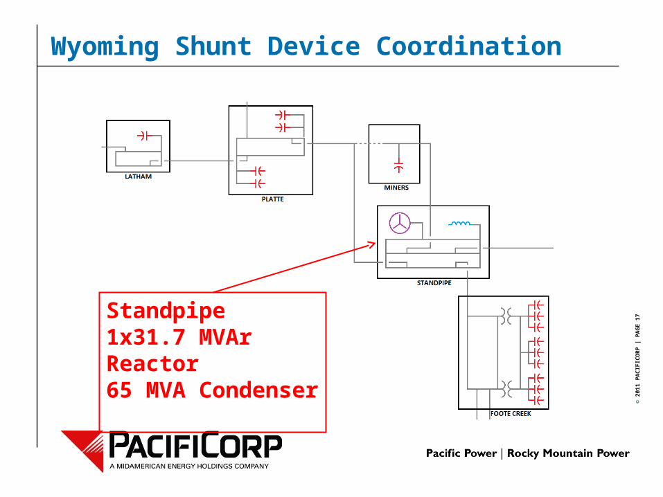
Wyoming Shunt Device Coordination
Standpipe1x31.7 MVAr Reactor65 MVA Condenser
© 2
011
PA
CIF
ICO
RP
| P
AG
E 1
8
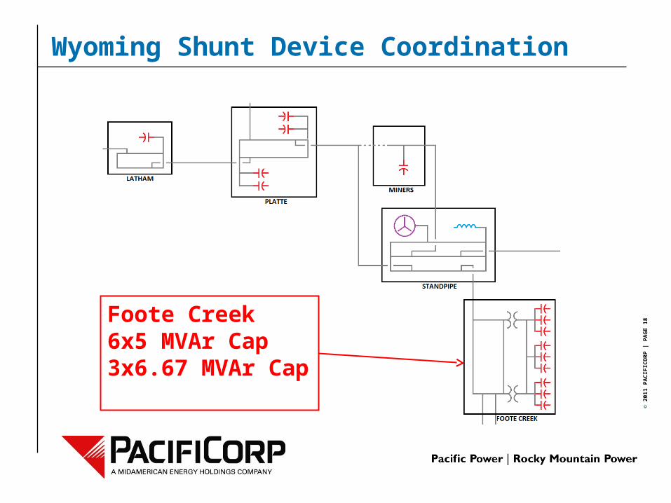
Wyoming Shunt Device Coordination
Foote Creek6x5 MVAr Cap3x6.67 MVAr Cap
© 2
011
PA
CIF
ICO
RP
| P
AG
E 1
9
Wyoming Shunt Device Coordination
– Shunt devices at Latham and Platte will be controlled locally utilizing coordinated switching setpoints and time delays.
– Shunt devices at Miners and Standpipe may be set to control local voltage utilizing coordinated switching setpoints and time delays; however their primary mode of operation will be the condenser dynamic expansion scheme.
– Shunt devices at Foote Creek will be controlled to minimize VAr exchange to the 230 kV system, with 34.5 kV voltage supervision.

© 2
011
PA
CIF
ICO
RP
| P
AG
E 2
0
Wyoming Shunt Device Coordination
– Shunt devices will be controlled utilizing a dual-band control philosophy.
Vhi-slow
Vlow-slow
Vhi-fast
Vlow-fast
Slow Control Deadband
Fast Control Deadband
Insert Reactor or Trip Capacitor with Slow Time Delay Setting
Trip Reactor or Insert Capacitor with Slow Time Delay Setting
Insert Reactor or Trip Capacitor with Fast Time Delay Setting
Trip Reactor or Insert Capacitor with Fast Time Delay Setting
© 2
011
PA
CIF
ICO
RP
| P
AG
E 2
1
– Questions?
Questions