Embed Size (px)
Citation preview

1RE 83 001/07.99
RE 83 001/07.99
STAR – Linear Motion Slides

2 RE 83 001/07.99
STAR – Linear Motion Technology
REG. No.1617 - 03
Rexroth Star GmbH
D-97419 Schweinfurt
Ball Rail Systems Standard Ball Rail Systems
Ball Rail Systems with Aluminum Runner Blocks
Super Ball Rail Systems
Wide Ball Rail Systems
Miniature Ball Rail Systems
Cam Roller Guides
Accessories
Roller Rail Systems
Linear Bushings and Shafts Linear Bushings
Linear Sets
Shafts
Shaft Support Rails
Shaft Support Blocks
Ball Transfer Units
Screw Drives
Linear Motion Systems Linear Motion Slides
Linear Modules
Compact Modules
Ball Rail Tables
ALU-STAR Profile System
Controllers, Motors, Electrical Accessories
Linear Actuators
Roller Rail is a trademark ofRexroth Star GmbH, Germany.
STAR, Ball Rail and are trademarks registered forRexroth Star GmbH, Germany.

3RE 83 001/07.99
STAR – Linear Motion Slides
A Solution to Many Problems 4
Product Overview 6
Structure 12
Technical Data 14
Load Capacities and Moments 15
General Information 16
Technical Notes 18
- Size 8-65/12-85 18
- Size 16-100/20-130 20
- Size 25-160/30-180 22
- Size 40-230/50-280 24
Linear Motion Slides, Closed Type without Drive Unit 26
Linear Motion Slides, Closed Type with Ball Screw Drive 30
Linear Motion Slides, Open Type without Drive Unit 38
Linear Motion Slides, Open Type with Ball Screw Drive 42
Motor Attachment 50
Linear Motion Slides with Toothed Belt Drive 52- Structure and Technical Data 52
Switch Mounting Arrangements 60
Motors 63
Documentation 66
Inquiry/Order Form 67

4 RE 83 001/07.99
STAR – Linear Motion Slides
• Driving
• Transporting
• Positioning
The tasks
Length
Load capacities and moments
Static load
Speed
Precision
Documentation
A Solution to Many Problems
System completewith drive unit
Switch mounting arrangements
Version
Total height
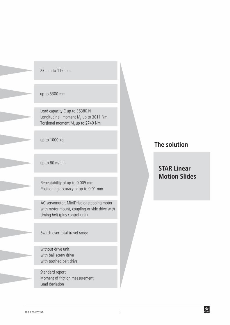
5RE 83 001/07.99
The solution
STAR LinearMotion Slides
up to 5300 mm
Load capacity C up to 36380 NLongitudinal moment ML up to 3011 NmTorsional moment Mt up to 2740 Nm
up to 1000 kg
up to 80 m/min
Standard reportMoment of friction measurementLead deviation
23 mm to 115 mm
Repeatability of up to 0.005 mmPositioning accuracy of up to 0.01 mm
AC servomotor, MiniDrive or stepping motorwith motor mount, coupling or side drive withtiming belt (plus control unit)
Switch over total travel range
without drive unitwith ball screw drivewith toothed belt drive

6 RE 83 001/07.99
Product Overview
STAR Linear Motion Slides:
closed type - for cantilever-type installation
open type - for installation with shaft support rails
Particularly smooth running andlong service life thanks to STARSuper Linear Bushings
Lubrication points at bothsides of the carriage, for greaselubrication only
Oil and moisture-proofPU bellows-type protectivecover (the last fold ismechanically clamped)
without drive unit
Various possibilities formotor attachment
with PrecisionBall Screw Assembly
Higher travel speeds possiblewith larger ball screw drives
One-point lubrication
STAR – Linear Motion Slides
7RE 83 001/07.99
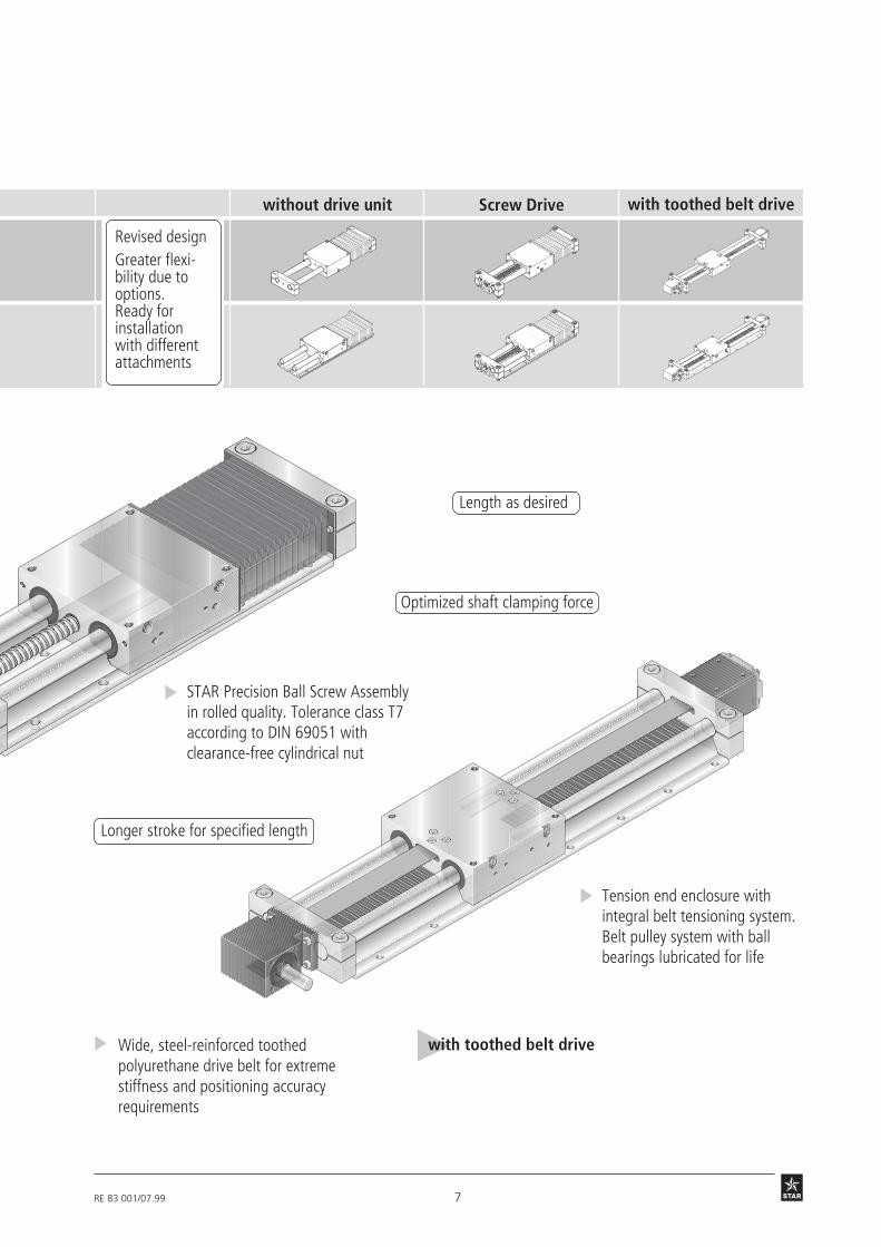
without drive unit
Longer stroke for specified length
STAR Precision Ball Screw Assemblyin rolled quality. Tolerance class T7according to DIN 69051 withclearance-free cylindrical nut
Tension end enclosure withintegral belt tensioning system.Belt pulley system with ballbearings lubricated for life
Wide, steel-reinforced toothedpolyurethane drive belt for extremestiffness and positioning accuracyrequirements
with toothed belt drive
Length as desired
with toothed belt driveScrew Drive
Optimized shaft clamping force
Revised designGreater flexi-bility due tooptions.Ready forinstallationwith differentattachments

8 RE 83 001/07.99
Product OverviewSTAR – Linear Motion Slides
VRDM 368VRDM 397VRDM 3910VRDM 3913
MKD 25B-144-KG1MKD 41B-144 KG1MKD 71B-061 KG1MKD 71B-097 KG1
MMD 022AMMD 042AMMD 082A
MiniDrive
Digital AC servomotor
3-phase stepping motor
Motor Selectionin accordance with controllers andcontrol systems
A choice can be made between severaldifferent motor/controller combinations toachieve the most cost-efficient solution foreach customer application. The motor/controller combination must always betaken into account when sizing the drive.
For more detailed information on motorsand control systems, please refer tocatalog RE 82700 “Controllers, Motors,Electrical Accessories”.

9RE 83 001/07.99
Digital controller
RS232
Auto
Hand
STAR step mannesmannRexroth
engineering
Deutsche Star
Digital controllerThe low-cost solution forsingle-axis and multi-axissystems
Digital positioningmodule and DLC controlsThe universal solution forone axis
Digital controllers and CLManalog positioning moduleThe convenient solution formulti-axis systems
Power output sectionfor control cabinet installation
PC controller boardStepping motor controller
Single-axis and multiple-axis positioning controlswith power output sectionThe complete solution
Linear Motion Slides can be suppliedcomplete with motor, controller andcontrol system.
STARstep
PC
WD3
DMD
DDS
DKS
DKC
RS232
Auto
Hand
STAR step mannesmannRexroth
engineering
Deutsche Star
RS232
Auto
Hand
STAR step mannesmannRexroth
engineering
Deutsche Star

10 RE 83 001/07.99
Product OverviewType designation (size)The linear motion slides are designatedaccording to type and size.
The term slide is used to describe aspecific combination of type and size.
“Linear motion slide” is abbreviated toslide in the following tables.
Slide (example) =
System = Linear Motion Slide (S)
Guideway = Closed-type linear bushing (G)Open-type linear bushing (O)
Drive unit = Without drive unit (O)Precision Ball Screw Assembly (K)Toothed belt (R)
Dimensionsof guideway =
Overallwidth =
Type
S G K 16- 100
d
B
SGK
SGO
SGR
Type Slide Guideway Drive unit
Linear MotionSlidesClosed type
SOK
SOO
SOR
Toothed belt drive
Toothed belt drive
Precision Ball ScrewAssembly
Precision Ball ScrewAssembly
Linear MotionSlidesOpen type
without drive unit
without drive unit
Super Linear Bushing Aopen type
Super Linear Bushing Aclosed type
1) Size 8-65 with Standard Linear Bushing
STAR – Linear Motion Slides
Size

11RE 83 001/07.99
As far as the desired service life is con-cerned, loads of up to approximately20% of the dynamic load and momentvalues (C, Mt, ML) have proved acceptable.
Suitable load(recommended value on the basisof past experience)
The following values may not be exceeded:
– the maximum permissible deflection
– the maximum permissible drive torque
Size: d-B
Page 26 1040 2500 3050 6040 11820 14360 24660 36060
Page 30 2500 3050 6040 11820 14360 24660 36060
Page 56 11820
Page 40 2850 3440 6100 11950 14520 24950 36380
Page 56 11950
Page 44 2850 3440 6100 11950 14520 24950 36380
Dynamic load capacity C (N)
Bd
The dynamic load capacities and momentsare based on 100,000 m travel. However,a travel of just 50,000 m is often taken asa basis. If this is the case, for comparisonpurposes:
Multiply values C, Mt and ML by 1.26.
Note on dynamic load capacitiesand moments:
8-65 12-85 16-100 20-130 25-160 30-180 40-230 50-280
12 RE 83 001/07.99
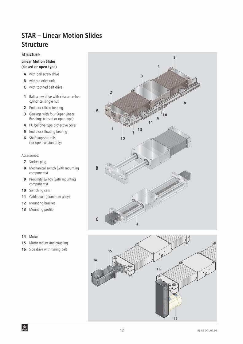
StructureStructureLinear Motion Slides(closed or open type)
A with ball screw drive
B without drive unit
C with toothed belt drive
1 Ball screw drive with clearance-freecylindrical single nut
2 End block fixed bearing
3 Carriage with four Super LinearBushings (closed or open type)
4 PU bellows-type protective cover
5 End block floating bearing
6 Shaft support rails(for open version only)
Accessories:
7 Socket-plug
8 Mechanical switch (with mountingcomponents)
9 Proximity switch (with mountingcomponents)
10 Switching cam
11 Cable duct (aluminum alloy)
12 Mounting bracket
13 Mounting profile
14 Motor
15 Motor mount and coupling
16 Side drive with timing belt
STAR – Linear Motion Slides
1
2
3
4
5
11
7
8
910
12
13
6
A
B
C
15
14
16
14

13RE 83 001/07.99
2 31 4
6
7
Fv
4
1
3
5
8
2
9
Motor attachment via sidedrive with timing beltFor Linear Motion Slides from size 25-160and up, the motor can be attached via aside drive with timing belt. This results ina shorter overall length compared to amotor attachment with motor mount andcoupling.
The compact enclosed housing providesbelt protection and secures the motor.
In addition, different gear ratios are available:
i = 1 : 1
i = 1 : 1.5 (size 25-160, 30-180)
i = 1 : 2 (size 40-230, 50-280)The side drive with timing belt can bemounted in four directions:
– bottom, top (RV01 and RV02)– left, right (RV03 and RV04)
1 Linear Motion Slide2 Drawn, anodized aluminum frame3 Toothed belt4 AC servomotor5 Pre-tensioning of the toothed belt:
Apply pre-tensioning force Fv to motor(Fv will be indicated on delivery)
6 Attachment of belt pulleys withclamping assemblies
7 Cover plate8 End cover9 On sizes 25-160 and 30-180:
Ball screw journal with additionalsupport bearing
Motor attachment with mountand couplingA motor can be attached via a mountand coupling to all Linear Motion Slidesequipped with a ball screw drive.
The motor mount serves both to attach themotor to the Linear Motion Slide and as anenclosed housing for the coupling.
The coupling transmits the motor drivetorque free of stresses to the LinearMotion Slide drive shaft.
Our standard couplings compensate forthe thermal expansion of the system.
If other makes of couplings are used, the ther-mal expansion must be taken into account.
1 Motor2 Motor mount3 Coupling4 Linear Motion Slide
14 RE 83 001/07.99
Technical DataSTAR – Linear Motion Slides
1700
1600
2900
250 84
20 x 5
20 x 20
25 x 10
2.6
6.9
5.0
1.7
4.6
3.3
0.4
Permissible torqueup to length L = … at (1)
Reduced mass momentof inertia at
(· 10-6 kgm2)(· 10-6 kgm2)
i = 1.5i = 1i = 1.5i = 1
(Nm)(Nm)(mm)
MRvL MRv JRv JRvBall screwLinear MotionSlide
Motor
Friction moment MRRv (Nm)
Gear ratio i = …
MKD 71B
0.45
Permissible torqueup to length L = … at (1)
Reduced mass momentof inertia at
(· 10-6 kgm2)(· 10-6 kgm2)
i = 2i = 1i = 2i = 1
(Nm)(Nm)(mm)
MRvL MRv JRv JRv
Technical data of AC servomotorsand MiniDrive
MKD 41B-144 KG1Motor
170 + 16
2.2
4.65
2.7
Maximum effective speed nmax (1/min)
Rated torque MMN (Nm)
Maximum torque Mmax (Nm)
Mass moment of inertia JM + JBr (10-6 kgm2)
Brake holding torque MBr (Nm)
Mass with brake mBr (kg)
MKD 71B-061
870 + 38
5
9.17
8
d0 x P
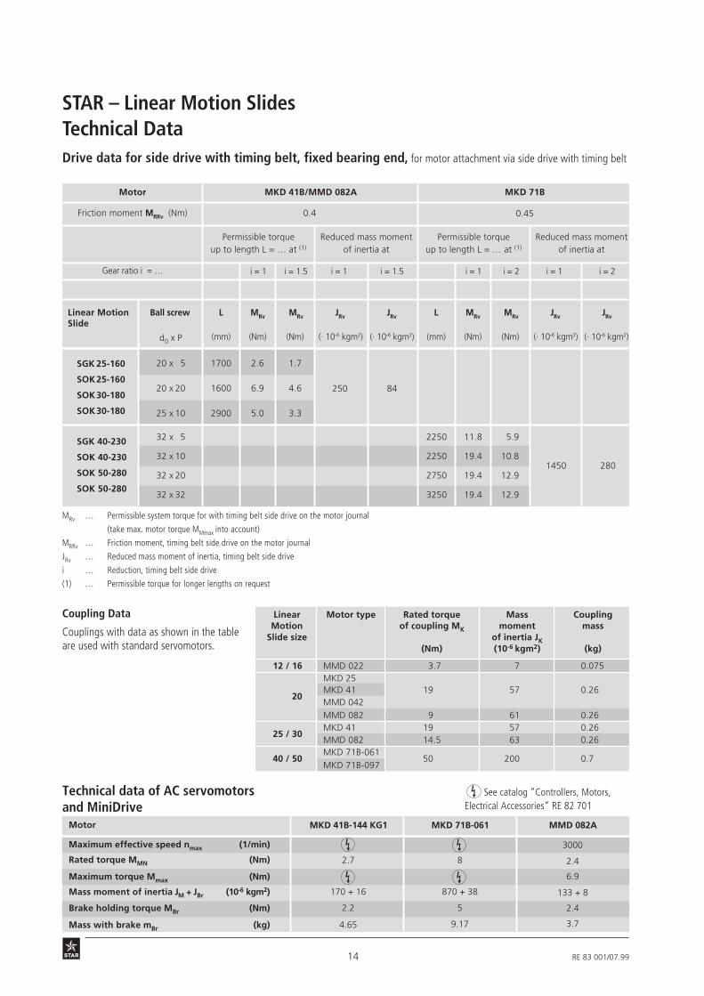
Drive data for side drive with timing belt, fixed bearing end, for motor attachment via side drive with timing belt
MRv … Permissible system torque for with timing belt side drive on the motor journal
(take max. motor torque MMmax into account)
MRRv … Friction moment, timing belt side drive on the motor journal
JRv … Reduced mass moment of inertia, timing belt side drive
i … Reduction, timing belt side drive
(1) … Permissible torque for longer lengths on request
See catalog “Controllers, Motors,Electrical Accessories” RE 82 701
MKD 41B/MMD 082A
SGK 25-160
SOK25-160
SOK30-180
SOK30-180
SGK 40-230
SOK 40-230
SOK 50-280
SOK 50-280
32 x 5
32 x 10
32 x 20
32 x 32
2250
2250
2750
3250
11.8
19.4
19.4
19.4
5.9
10.8
12.9
12.9
1450 280
MMD 082A
3000
2.4
6.9
133 + 8
2.4
3.7
Coupling Data
Couplings with data as shown in the tableare used with standard servomotors.
Linear Motor type Rated torque Mass CouplingMotion of coupling MK moment mass
Slide size of inertia JK(Nm) (10-6 kgm2) (kg)
12 / 16 MMD 022 3.7 7 0.075MKD 25
20MKD 41 19 57 0.26MMD 042MMD 082 9 61 0.26
25 / 30MKD 41 19 57 0.26MMD 082 14.5 63 0.26
40 / 50MKD 71B-061
50 200 0.7MKD 71B-097
15RE 83 001/07.99
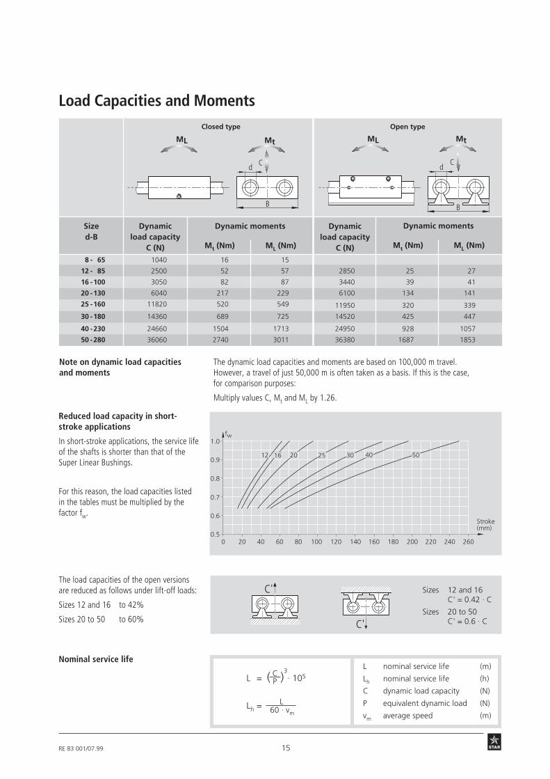
Closed type
Sized-B
Dynamic moments
Mt (Nm) ML (Nm)
Dynamicload capacity
C (N)
Open type
Dynamicload capacity
C (N)8 - 65 1040 16 15
12 - 85 2500 52 57
16 -100 3050 82 87
20 -130 6040 217 229
25 -160 11820 520 549
30 -180 14360 689 725
40 -230 24660 1504 1713
50 -280 36060 2740 3011
2850 25 27
3440 39 41
6100 134 141
11950 320 339
14520 425 447
24950 928 1057
36380 1687 1853
Reduced load capacity in short-stroke applications
In short-stroke applications, the service lifeof the shafts is shorter than that of theSuper Linear Bushings.
For this reason, the load capacities listedin the tables must be multiplied by thefactor fw.
MtML
C
B
d
B
MtML
Cd
C'
C' Sizes 12 and 16C' = 0.42 · C
Sizes 20 to 50C' = 0.6 · C
0 20 40 60 80 100 120 140 160 180 200 220 240 2600.5
0.6
0.7
0.8
0.9
1.0fw
Stroke(mm)
12 16 20 25 30 40 50
PL = ( )3· 105
Lh = L
C
60 · vm
L nominal service life (m)
Lh nominal service life (h)
C dynamic load capacity (N)
P equivalent dynamic load (N)
vm average speed (m)
Note on dynamic load capacitiesand moments
The dynamic load capacities and moments are based on 100,000 m travel.However, a travel of just 50,000 m is often taken as a basis. If this is the case,for comparison purposes:
Multiply values C, Mt and ML by 1.26.
Nominal service life
The load capacities of the open versionsare reduced as follows under lift-off loads:
Sizes 12 and 16 to 42%
Sizes 20 to 50 to 60%
Dynamic moments
Mt (Nm) ML (Nm)
Load Capacities and Moments

16 RE 83 001/07.99
STAR – Linear Motion SlidesGeneral Information
tan αmax = 8.72 · 10-3 =̂ 0.5°
tan α ≤ tan αmax
Linear Motion Slides are also available with:
- corrosion resistant steel shafts to DIN 17230 / EN 10088
- STAR Resist steel shafts: zinc/iron coating with yellow chromating
For further details on STAR Resist, please ask for catalog RE 82 050.
For further details on STAR Linear Bushings and Precision Steel Shafts,please ask for catalog RE 83 100.
Delivered as separate parts. The carriage is mounted as a sub-assembly.The fixing screws are not included in the package.
Open Type SOO:
The Precision Steel Shafts are screwed to the Shaft Support Rails.
tan αmax = 10 · 10-4Size 8-65:
Assemblies without drive unit:
Delivery condition:
Length L:
Assemblies with drive unit: The Linear Motion Slides with ball screw drive and toothed belt drive(SGK, SGR, SOR and SOK) are delivered fully assembled and greased.
Linear Motion Slides consist of components of varying length and assemblies of fixedlength. The length-dependent components are cut to size to suit each particular appli-cation. Linear Motion Slides can thus be custom-designed and completed in a variety oflengths (infinitely variable). Lengths exceeding the specified maximum Lmax are availableon request.
Permissible shaft deflection inthe Linear Bushing closed type:
Due to the use of STAR Super Linear Bushings (except for Linear Motion Slidesize 8-65), higher shaft deflection is permissible than for conventional linear bearings.Selection of the length (L) and the size of slide should take account of the permissibleshaft deflection (tan α).
Maximum permissible drivetorque Mper:
The values of Mper given in the graphs (see Technical Notes) are based on the followingassumptions:
• Horizontal operation
• No radial load on the ball screw drive journal
• The torque rating of the coupling is not taken into account
The maximum permissible drive torque (see Technical Notes) is reduced for ball screwdrives with keyway. The keyway produces a notch effect and reduces the effective dia-meter. (Information on side drive with timing belt available on request.)
Weight of the Linear Motion Slide:
Shafts for Linear Motion Slideswithout drive unit:
Weight calculation does not include motor attachment, switches or side drive withtiming belt.
Weight (kg/mm) · Length L (mm) + Weight of all fixed-length components (kg)

17RE 83 001/07.99

18 RE 83 001/07.99
STAR – Linear Motion Slides
L/2
L
F
α
tan α ≤ tan αmax
Technical Notes – Size 8-65/12-85
8-65 Slide Dynamic loadcapacity
C(N)
Dynamic moments Movedmass
(kg)
SlideweightL in mm
(kg)
Max. lengthLmax
(mm)
Frictionalforce
(N)
Closed type
Mt(Nm)
ML(Nm)
tan α = F · (L - 9) · 4.970 · 10-8
tan αmax = 10 · 10-4
Permissible shaft deflection in theLinear Bushing1)
tan α Shaft deflectionF External load (N)L Dimension “L” (mm)
Linear Motion Slide SGO 8 - 65incorporates Standard Linear Bushings.The load capacity or service life of the Slidewill therefore be reduced with increasingshaft deflection.
For further information refer to catalogRE 83 100 “Linear Bushings and Shafts”.
SGO 8 - 65 1040 16 15 0.28 0.0008 · L + 0.39 700 3
See section on Load Capacities and Moments.
1) Also refer to “General Information”
19RE 83 001/07.99
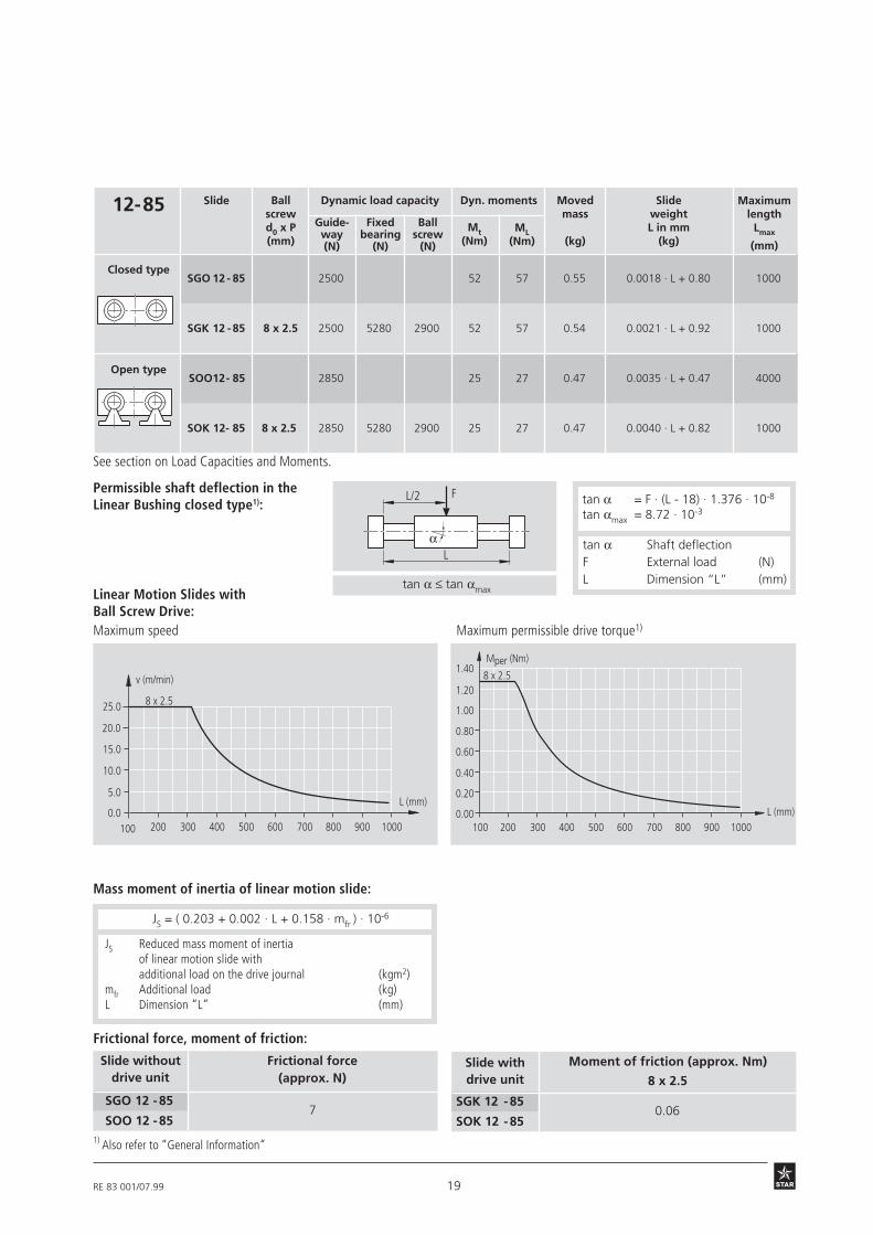
12-85 Slide
Closed type
Open type
Mt(Nm)
Ballscrewd0 x P(mm)
Dynamic load capacity Dyn. moments
ML(Nm)
Movedmass
(kg)
SlideweightL in mm
(kg)
Maximumlength
Lmax
(mm)
Guide-way(N)
Fixedbearing
(N)
Ballscrew
(N)
SGO 12 - 85 2500 52 57 0.55 0.0018 · L + 0.80 1000
SGK 12 - 85 8 x 2.5 2500 5280 2900 52 57 0.54 0.0021 · L + 0.92 1000
SOO12- 85 2850 25 27 0.47 0.0035 · L + 0.47 4000
SOK 12- 85 8 x 2.5 2850 5280 2900 25 27 0.47 0.0040 · L + 0.82 1000
Permissible shaft deflection in theLinear Bushing closed type1): tan α = F · (L - 18) · 1.376 · 10-8
tan αmax = 8.72 · 10-3
Linear Motion Slides withBall Screw Drive:Maximum speed Maximum permissible drive torque1)
Mass moment of inertia of linear motion slide:
L/2
L
F
α
tan α ≤ tan αmax
tan α Shaft deflectionF External load (N)L Dimension “L” (mm)
100 200 300 400 500 600 700 8000.00
0.20
0.40
0.60
0.80
1.00
L (mm)
8 x 2.5
900 1000
1.20
1.40Mper (Nm)
1000.0
5.0
10.0
15.0
20.0
25.0
v (m/min)
L (mm)
8 x 2.5
200 300 400 500 600 700 800 900 1000
Frictional force, moment of friction:
SOO 12 - 85
SGO 12 - 85
Frictional force(approx. N)
7SOK 12 - 85
SGK 12 - 850.06
Moment of friction (approx. Nm)
8 x 2.5
1) Also refer to “General Information”
See section on Load Capacities and Moments.
Slide withdrive unit
Slide withoutdrive unit
JS = ( 0.203 + 0.002 · L + 0.158 · mfr ) · 10-6
JS Reduced mass moment of inertiaof linear motion slide withadditional load on the drive journal (kgm2)
mfr Additional load (kg)L Dimension “L” (mm)

20 RE 83 001/07.99
STAR – Linear Motion SlidesTechnical Notes – Size 16-100/20-130
Linear Motion Slides withBall Screw Drive:Maximum speed
tan α Shaft deflectionF External load (N)L Dimension “L” (mm)
tan α = F · (L - 21) · 5.381 · 10-9
tan αmax = 8.72 · 10-3
Mass moment of inertia of linear motion slide:
Frictional force, moment of friction:
Maximum permissible drive torque1)
Frictional force(approx. N)
SOO 16-100
SGO 16 -1009
Moment of friction (approx. Nm)12 x 5
SOK 16-100
SGK 16-1000.13
250 375 500 625 750 875 1000 1125 1250 1375 15000.0
10.020.030.040.050.060.0
v (m/min)
L (mm)
12 x 5
12 x 1080.070.0
90.0
250 350 450 550 650 850 950 1050 1150 1250
0.00
0.50
1.00
1.50
2.00
2.50
L (mm)
Mper (Nm)
750 1350 1450
12 x 5
12 x 10
tan α ≤ tan αmax
1) Also refer to “General Information”
See section on Load Capacities and Moments.
12 x 10
0.16
0.633
2.533
Ball screw:d0 x P k2
1.088
2.367
k1
12 x 5
12 x 10
k3
0.013
0.013
Constant
Slide withdrive unit
Slide withoutdrive unit
JS = ( k1 + k2 · L + k3 · mfr ) · 10-6
JS Reduced mass moment of inertiaof linear motion drives withadditional load on the drive journal (kgm2)
k1, k2, k3 Constants (see table)mfr Additional load (kg)L Dimension “L” (mm)
L/2
L
F
α
16-100 Slide
Closed type
Open type
Mt(Nm)
Ballscrewd0 x P(mm)
Dynamic load capacity Dyn. moments
ML(Nm)
Movedmass
(kg)
SlideweightL in mm
(kg)
Maximumlength
Lmax
(mm)
SGO 16-100 3050 82 87 0.82 0.003 · L + 1.2 1500
SOK 16-100 3440 5280 39 41 0.76 0.006 · L + 1.3 150049903270
12 x 512 x 10
49903270
12 x 512 x 10
SGO 16-100 3440 39 41 0.75 0.005 · L + 0.75 4000
Permissible shaft deflection in theLinear Bushing closed type1):
Guide-way(N)
Fixedbearing
(N)
Ballscrew
(N)

21RE 83 001/07.99
20-130 Slide
Closed type
Open type
Mt(Nm)
Ballscrewd0 x P(mm)
Dynamic load capacity Dyn. moments
ML(Nm)
Movedmass
(kg)
SlideweightL in mm
(kg)
Maximumlength
Lmax
(mm)
Permissible shaft deflection in theLinear Bushing closed type1): tan α = F · (L - 36) · 2.932 · 10-9
tan αmax = 8.72 · 10-3
SOO 20 -130 6100 134 141 1.6 0.008 · L + 1.6 4000
SOK 20-130 16 x 10 6100 13400 9600 134 141 1.6 0.010 · L + 2.7 2500
SGK 20 -130 16 x 10 6040 13400 9600 217 229 1.8 0.006 · L + 3.0 2500
16 x 16 6200
16 x 5 12300
16 x 16 6200
16 x 5 12300
L/2
L
F
α tan α Shaft deflectionF External load (N)L Dimension “L” (mm)tan α ≤ tan αmax
Maximum permissible drive torque1)
Ball screw drive with keyway: maximum drive torque 3.2 Nm
Linear Motion Slides withBall Screw Drive:Maximum speed
2500.0
L (mm)
500 750 1000 1250 1500 1750 2000 2250 2500
10.0
20.0
30.0
40.0
50.0
60.0
70.0
80.0v (m/min)
16 x 16
16 x 10
16 x 5
2500.00
L (mm)
500 750 1000 1250 1500 1750 2000 2250 2500
0.50
1.00
1.50
2.00
2.50
3.00
3.50
4.00 16 x 16
16 x 10
16 x 5
Mper (Nm)
See section on Load Capacities and Moments.
SGO 20 -130 6040 217 229 1.8 0.005 · L + 2.6 2500
JS = ( k1 + k2 · L + k3 · mfr ) · 10-6
SOO 20-130
SGO 20-130
Frictional force(approx. N)
11
Moment of friction (approx. Nm)
SGK 20-130
SOK 20-130
Frictional force, moment of friction:
JS Reduced mass moment of inertiaof linear motion slide withadditional load on the drive journal (kgm2)
k1, k2, k3 Constants (see table)mfr Additional load (kg)L Dimension “L” (mm)
16 x 5 16 x 10 16 x 16
0.40 0.43 0.46
Mass moment of inertia of linear motion slide:
1) Also refer to “General Information”
Slide withdrive unit
Slide withoutdrive unit
Ball screw: d0 x P k2k1 k3
Constant
16 x 5
16 x 10
16 x 16
3.238
6.692
13.878
0.039
0.039
0.039
0.633
2.533
6.485
Guide-way(N)
Fixedbearing
(N)
Ballscrew
(N)

22 RE 83 001/07.99
STAR – Linear Motion SlidesTechnical Notes – Size 25-160/30-180
L/2
L
F
α
tan α ≤ tan αmax
Ball screw drive with keyway: maximum drive torque 4.5 Nm
25-160 Slide
Closed type
Open type
Mt(Nm)
Ballscrewd0 x P(mm)
Dynamic load capacity Dyn. moments
ML(Nm)
Movedmass
(kg)
SlideweightL in mm
(kg)
Maximumlength
Lmax
(mm)
SGO 25-160 11820 520 549 3.3 0.008 · L + 4.8 3000
Permissible shaft deflection in theLinear Bushing closed type1):
tan α = F · (L - 43) · 1.468 · 10-9
tan αmax = 8.72 · 10-3
SOO 25-160 11950 320 339 2.8 0.011 · L + 2.8 5300
SOK 25-160 20 x 20 11950 17000 9100 320 339 2.9 0.015 · L + 5.0 3000
SGK 25-160 20 x 20 11820 17000 9100 520 549 3.3 0.011 · L + 5.5 3000
25 x 10 15800
20 x 5 14300
25 x 10 15800
20 x 5 14300
Linear Motion Slides withBall Screw Drive:Maximum speed
tan α Shaft deflectionF External load (N)L Dimension “L” (mm)
2500.0
L (mm)
500 750 1000 1250 1500 1750 2000 2250 2500
10.0
20.0
30.0
40.0
50.0
60.0
70.0
80.0v (m/min)
2750 3000
20 x 20
25 x 10
20 x 5
2500.0
L (mm)
500 750 1000 1250 1500 1750 2000 2250 2500
1.00
2.00
3.00
4.00
5.00
6.00
7.00
8.00
2750 3000
20 x 20
25 x 10
20 x 5
Mper (Nm)
Maximum permissible drive torque1)
See section on Load Capacities and Moments.
JS = ( k1 + k2 · L + k3 · mfr ) · 10-6
SOO 25-160
SGO 25-160
Frictional force(approx. N)
14
Moment of friction (approx. Nm)
SGO 25-160
SOK 25-160
Frictional force, moment of friction:
JS Reduced mass moment of inertiaof linear motion slide withadditional load on the drive journal (kgm2)
k1, k2, k3 Constants (see table)mfr Additional load (kg)L Dimension “L” (mm)
20 x 5 20 x 20 25 x 10
0.53 0.64 0.66
Mass moment of inertia of linear motion slide:
1) Also refer to “General Information”
Slide withdrive unit
Slide withoutdrive unit
Ball screw:d0 x P k2k1 k3
Constant
20 x 5
20 x 20
25 x 10
8.216
39.990
23.575
0.100
0.100
0.256
0.633
10.132
2.533
Guide-way(N)
Fixedbearing
(N)
Ballscrew
(N)
23RE 83 001/07.99
L/2
L
F
α
tan α ≤ tan αmax
Ball screw drive with keyway: maximum drive torque 4.5 Nm
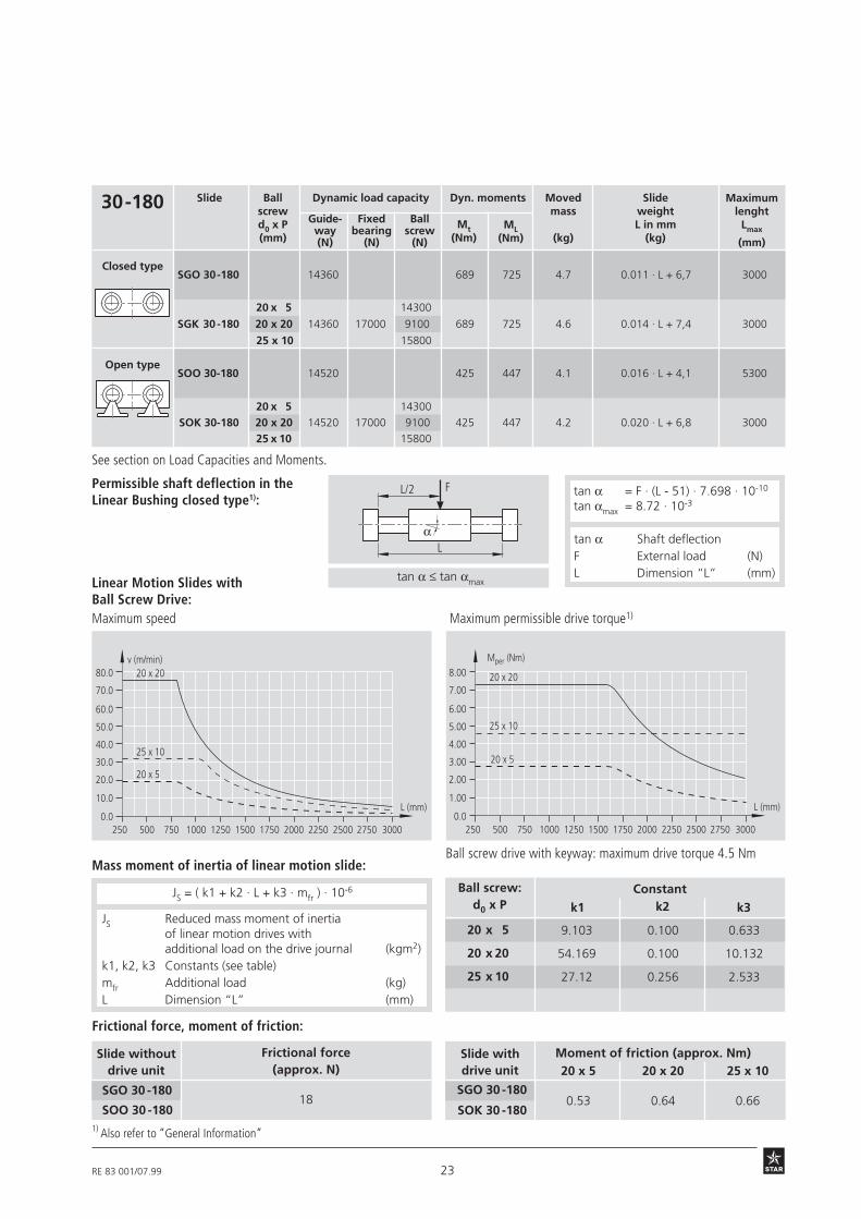
30-180 Slide
Closed type
Open type
Mt(Nm)
Ballscrewd0 x P(mm)
Dynamic load capacity Dyn. moments
ML(Nm)
Movedmass
(kg)
SlideweightL in mm
(kg)
Maximumlenght
Lmax
(mm)
Permissible shaft deflection in theLinear Bushing closed type1):
SOO 30-180 14520 425 447 4.1 0.016 · L + 4,1 5300
SOK 30-180 20 x 20 14520 17000 9100 425 447 4.2 0.020 · L + 6,8 3000
SGK 30 -180 20 x 20 14360 17000 9100 689 725 4.6 0.014 · L + 7,4 3000
25 x 10 15800
20 x 5 14300
Linear Motion Slides withBall Screw Drive:Maximum speed
SGO 30-180 14360 689 725 4.7 0.011 · L + 6,7 3000
tan α Shaft deflectionF External load (N)L Dimension “L” (mm)
Maximum permissible drive torque1)
2500.0
L (mm)
500 750 1000 1250 1500 1750 2000 2250 2500
10.0
20.0
30.0
40.0
50.0
60.0
70.0
80.0v (m/min)
2750 3000
20 x 20
25 x 10
20 x 5
2500.0
L (mm)
500 750 1000 1250 1500 1750 2000 2250 2500
1.00
2.00
3.00
4.00
5.00
6.00
7.00
8.00
2750 3000
20 x 20
25 x 10
20 x 5
Mper (Nm)
tan α = F · (L - 51) · 7.698 · 10-10
tan αmax = 8.72 · 10-3
See section on Load Capacities and Moments.
20 x 5 14300
25 x 10 15800
1) Also refer to “General Information”
JS = ( k1 + k2 · L + k3 · mfr ) · 10-6
SOO 30 -180
SGO 30 -180
Frictional force(approx. N)
18
Moment of friction (approx. Nm)
SGO 30 -180
SOK 30 -180
Frictional force, moment of friction:
JS Reduced mass moment of inertiaof linear motion drives withadditional load on the drive journal (kgm2)
k1, k2, k3 Constants (see table)mfr Additional load (kg)L Dimension “L” (mm)
20 x 5 20 x 20 25 x 10
0.53 0.64 0.66
Mass moment of inertia of linear motion slide:
Slide withdrive unit
Slide withoutdrive unit
Ball screw:d0 x P k2k1 k3
Constant
20 x 5
20 x 20
25 x 10
9.103
54.169
27.12
0.100
0.100
0.256
0.633
10.132
2.533
Guide-way(N)
Fixedbearing
(N)
Ballscrew
(N)

24 RE 83 001/07.99
L/2
L
F
α
tanα ≤ tanαmax
Ball screw drive with keyway: maximum drive torque 18 Nm
40-230 Slide
Closed type
Open type
Mt(Nm)
Ballscrewd0 x P(mm)
Dynamic load capacity Dyn. moments
ML(Nm)
Movedmass
(kg)
SlideweightL in mm
(kg)
Maximumlength
Lmax
(mm)
Linear Motion Slides withBall Screw Drive:
SGO 40-230 24660 1504 1713 9.4 0.020 · L + 13.3 4000
32 x 10 2620032 x 5 21500
Permissible shaft deflection in theLinear Bushing closed type1):
Maximum speed
tan α = F · (L - 79) · 3.407 · 10-10
tan αmax = 8.72 · 10-3
tan α Shaft deflectionF External load (N)L Dimension “L” (mm)
Maximum permissible drive torque1)
32 x 5 21500
SOO 40-230 24950 928 1057 8.3 0.026 · L + 8.3 5300
0.0L (mm)
500 1000 1500 2000 2500
10.0
20.0
30.0
40.0
50.0
60.0
70.0
80.0
v (m/min)
3000 3500 4000
32 x 32
32 x 20
32 x 10
32 x 5
0.0L (mm)
500 1000 1500 2000 2500
5.0
10.0
15.0
20.0
25.0
30.0
35.0
40.0
Mper (Nm)
3000 3500 4000
32 x 32
32 x 20
32 x 10
32 x 5
See section on Load Capacities and Moments.32 x 32 17800
SOK 40-230 24950 26000 928 1057 8.5 0.032 · L + 13.2 400032 x 20 17900
32 x 32 17800
32 x 10 26200
32 x 20 17900SGK 40-230 24660 26000 1504 1713 9.3 0.025 · L + 14.2 4000
1) Also refer to “General Information”
JS = ( k1 + k2 · L + k3 · mfr ) · 10-6
SOO 40 -230
SGO 40 -230
Frictional force(approx. N)
22
Moment of friction (approx. Nm)
SGO 40 -230
SOK 40-230
Frictional force, moment of friction:
JS Reduced mass moment of inertiaof linear motion slide withadditional load on the drive journal (kgm2)
k1, k2, k3 Constants (see table)mfr Additional load (kg)L Dimension “L” (mm)
Mass moment of inertia of linear motion slide:
Slide withdrive unit
Slide withoutdrive unit
Ball screw:d0 x P k2k1 k3
Constant
32 x 5
32 x 10
32 x 20
32 x 32
51.8 53
69.446
138.21
268.83
0.712
0.712
0.667
0.667
0.633
2.535
10.132
25.938
32 x 5 32 x 10 32 x 20 32 x 32
1.14 1.24 1.23 1.27
STAR – Linear Motion SlidesTechnical Notes – Size 40-230 / 50-280
Guide-way(N)
Fixedbearing
(N)
Ballscrew
(N)

25RE 83 001/07.99
L/2
L
F
α
tan α ≤ tan αmax
50-280 Slide
Closed type
Open type
Mt(Nm)
Ballscrewdo x P(mm)
Dynamic load capacity Dyn. moments
ML(Nm)
Movedmass
(kg)
SlideweightL in mm
(kg)
Maximumlength
Lmax
(mm)
Linear Motion Slides withBall Screw Drive:
SGO 50-280 36060 2740 3011 16.4 0.031 · L + 22.1 4000
Permissible shaft deflection in theLinear Bushing closed type1):
Maximum speed
tan α = F · (L - 107) · 1.649 · 10-10
tan αmax = 8.72 · 10-3
tan α Shaft deflectionF External load (N)L Dimension “L” (mm)
Maximum permissible drive torque1)
32 x 32 17800
32 x 32 17800
SOO 50-280 36380 1687 1853 14.8 0.039 · L + 14.8 5300
0.0L (mm)
500 1000 1500 2000 2500
10.0
20.0
30.0
40.0
50.0
60.0
70.0
80.0
v (m/min)
3000 3500 4000
32 x 32
32 x 20
32 x 10
32 x 5
0.0L (mm)
500 1000 1500 2000 2500
5.0
10.0
15.0
20.0
25.0
30.0
35.0
40.0
Mper (Nm)
3000 3500 4000
32 x 32
32 x 20
32 x 10
32 x 5
Ball screw drive with keyway: maximum drive torque 18 Nm
1) Also refer to “General Information”
See section on Load Capacities and Moments.
32 x 10 26200
32 x 10 26200
32 x 20 17900SGK 50-280 36060 26000 2740 3011 16.0 0.036 · L + 22.8 4000
32 x 20 17900SOK 50-280 36380 26000 1687 1853 14.8 0.046 · L + 21.3 4000
32 x 5 21500
32 x 5 21500
JS = ( k1 + k2 · L + k3 · mfr ) · 10-6
SOO 50 -280
SGO 50 -280
Frictional force(approx. N)
27
Moment of friction (approx. Nm)
SGO 50 -280
SOK 50-280
Frictional force, moment of friction:
JS Reduced mass moment of inertiaof linear motion slide withadditional load on the drive journal (kgm2)
k1, k2, k3 Constants (see table)mfr Additional load (kg)L Dimension “L” (mm)
Mass moment of inertia of linear motion slide:
Slide withdrive unit
Slide withoutdrive unit
Ball screw:d0 x P k2k1 k3
Constant
32 x 5
32 x 10
32 x 20
32 x 32
56.025
87.214
209.28
468.78
0.712
0.712
0.667
0.667
0.633
2.533
10.132
25.938
1.14 1.25 1.25 1.30
32 x 5 32 x 10 32 x 20 32 x 32
Guide-way(N)
Fixedbearing
(N)
Ballscrew
(N)


RE 83 001/07.99 31
1) Observe maximum permissible torque. * Attachment can also be supplied withoutmotor. Please enter “00” for motor on order.
Standard Motor Type
i =
Motor attachment..
Motor..
without with
Cover..
without switch
Stan
dard
repo
rt
Mea
sure
men
tre
port
PNP NO
PNP NC 11 -. ±….
Externalswitching
cam
Externalsocket-
plug(loose)
17
Externalswitch
TypeLength in mm
Cable duct(loose)
01 03
01
01
01
00
00
00
01
01
01
01
1
1
1
1
00
16
13 -. ±….
Mechanical 15 -. ±….
Cable duct 20 - X....
02
00
00
00
for Motor1)*Mount
MMD 022 A
VRDM 368
MMD 022 A
VRDM 368
Carriage..
Documen-tation ..
Polyurethanebellows
Mounting side
Switching distanceTravel direction
Swit
ch a
cti-
vati
on p
oint
without cable duct 00
Switch type
58
27
03
02
03
02
58
27
1st switch .. - . ± ….. mm2nd switch .. - . ± ….. mm3rd switch .. - . ± ….. mmCable duct .. - . .... mmSocket-plug ..Switching cam ..
MKD 25 B
MKD 41 B
MMD 042 A
MMD 082 A
VRDM 397
VRDM 3910
50
10
59
60
28
29
02
01
05
06
03
03

32 RE 83 001/07.99
STAR – Linear Motion Slides, Closed Type with Ball Screw DriveDimension Drawings SGK 12-85 to SGK 20-130
Slide Dimensions (mm)
d A R B1 B4 B5 H H1 H2 H3 H4 H10 H13 H14 D1
h6 ± 0.02 ± 0.015
12 85 42 14 24 17 16 34 32 18 33 27 26.6 25 22
16 100 54 18 24 15 18 38 36 20 37 31 28.6 29 26
20 130 72 20 29 19 23 48 46 25 47 39 36.6 37.5 32
SGK 12 - 85
SGK 16 -100
SGK 20 -130
Slide Drive journalMounting geometry
6 28 18 25 2.1 40 33 23 M4 - 8 deep 53 9.5 11.5 M4-8 deep
6 28 18 25 2.1 40 33 23 M4 - 8 deep 60 11 14 M4-8 deep
9 40 25 34.5 2.1 52 40 28 M6-12 deep 74 15.5 18.5 M5-12 deep
d1 d2 L1 L2 Z1 E4 a b S4 F5 F6 F7 S5
h7 H7
Holes for locating bracketin both end blocks
For e
nd b
lock
A o
nly
See chapter on motor attachment for the motor attachment drawings.
Max. travel2
Max. travel2
Effective stroke2
Effective stroke2
Lube nipple
SGK 12 - 85
SGK 16 -100
SGK 20 -130
L/2
B15
ød1
H15H10
S15
B4B5
E4E2A
L1
L2
E1
A
A
B1 B12
L
H1
Overrun Overrun
All dimensions in mm
Diagrams to different scales
![STAR – Linear Bushings and Shafts - AHR International 51825 range to [°C] charac- friction [°C] DIN 51818 teristics bearings K2K-30 Lithium soap Petroleum –30 ... STAR – Linear](https://img.pdfslide.net/doc/110x75/5aee3fb17f8b9aa17b8c11b4/star-linear-bushings-and-shafts-ahr-international-51825-range-to-c-charac-.jpg)