Embed Size (px)
Citation preview
1
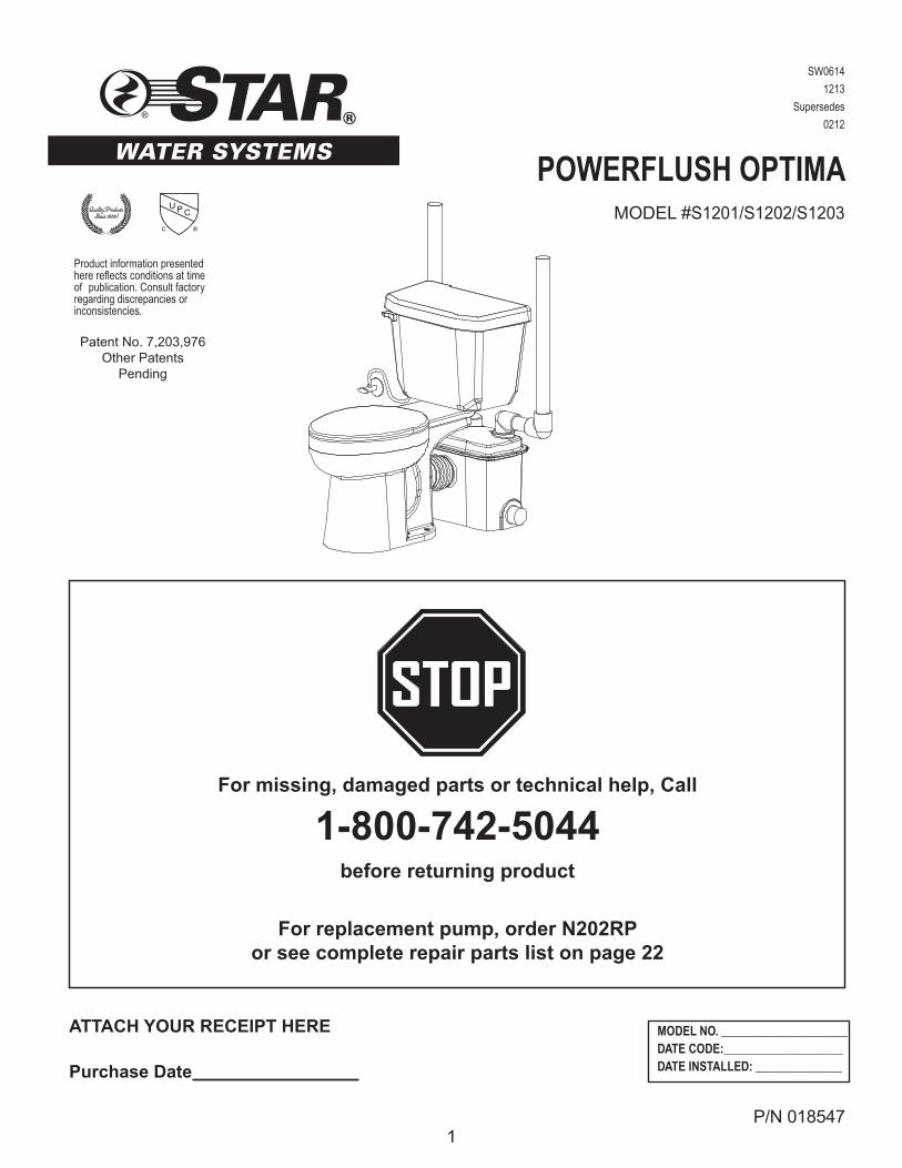
POWERFLUSH OPTIMAMODEL #S1201/S1202/S1203
ATTACH YOUR RECEIPT HERE
Purchase Date
STAR®
STOPFor missing, damaged parts or technical help, Call
1-800-742-5044
before returning product
For replacement pump, order N202RP or see complete repair parts list on page 22
SW0614
1213
Supersedes
0212
P/N 018547
Product information presented here reflects conditions at time of publication. Consult factory regarding discrepancies or inconsistencies.
MODEL NO. ___________________DATE CODE: __________________DATE INSTALLED: _____________
Patent No. 7,203,976Other Patents
Pending
Quality ProductsSince 1866!
2
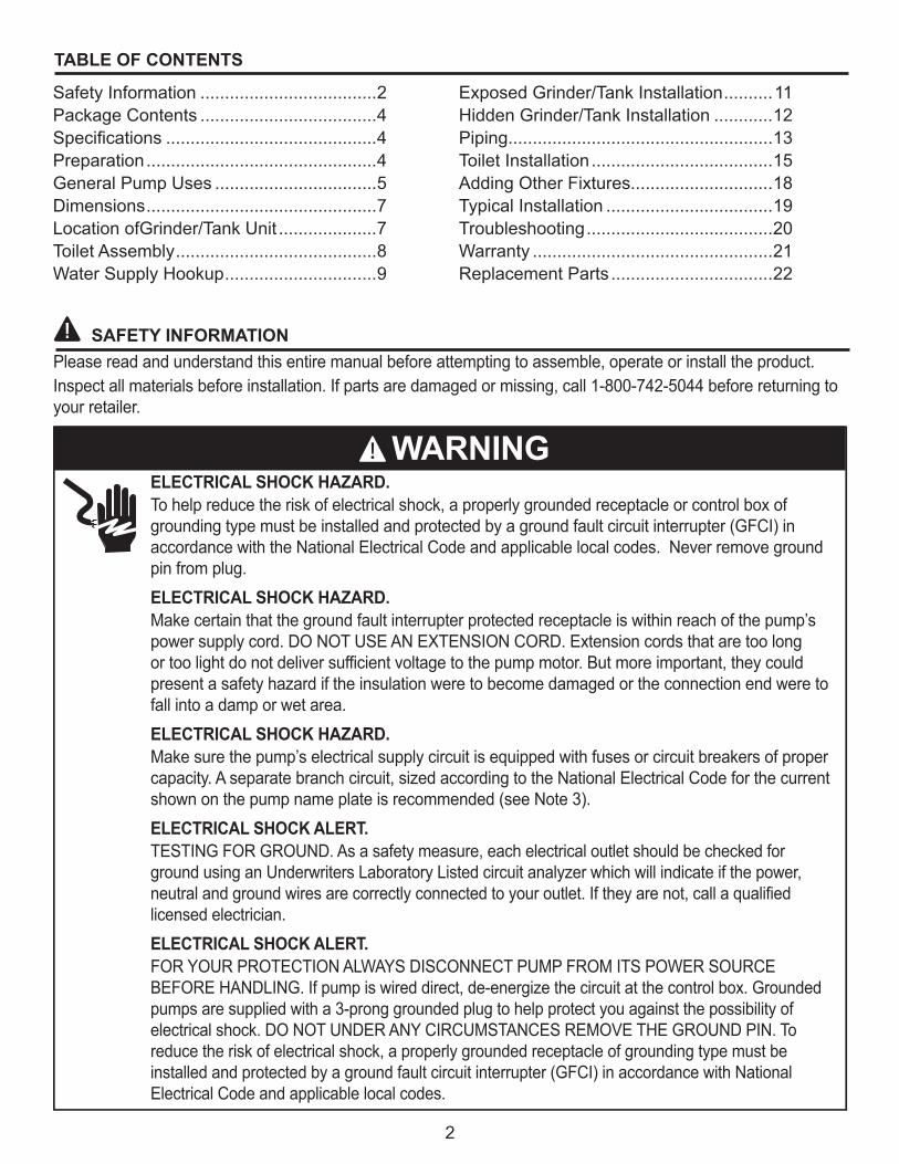
SAFETY INFORMATION
TABLE OF CONTENTS
Please read and understand this entire manual before attempting to assemble, operate or install the product. Inspect all materials before installation. If parts are damaged or missing, call 1-800-742-5044 before returning to your retailer.
Safety Information ....................................2Package Contents ....................................4Specifications ...........................................4Preparation ...............................................4General Pump Uses .................................5Dimensions ...............................................7Location ofGrinder/Tank Unit ....................7Toilet Assembly .........................................8Water Supply Hookup ...............................9
Exposed Grinder/Tank Installation ..........11Hidden Grinder/Tank Installation ............12Piping......................................................13Toilet Installation .....................................15Adding Other Fixtures.............................18Typical Installation ..................................19Troubleshooting ......................................20Warranty .................................................21Replacement Parts .................................22
ELECTRICAL SHOCK HAZARD.To help reduce the risk of electrical shock, a properly grounded receptacle or control box of grounding type must be installed and protected by a ground fault circuit interrupter (GFCI) in accordance with the National Electrical Code and applicable local codes. Never remove ground pin from plug. ELECTRICAL SHOCK HAZARD.Make certain that the ground fault interrupter protected receptacle is within reach of the pump’s power supply cord. DO NOT USE AN EXTENSION CORD. Extension cords that are too long or too light do not deliver sufficient voltage to the pump motor. But more important, they could present a safety hazard if the insulation were to become damaged or the connection end were to fall into a damp or wet area.ELECTRICAL SHOCK HAZARD.Make sure the pump’s electrical supply circuit is equipped with fuses or circuit breakers of proper capacity. A separate branch circuit, sized according to the National Electrical Code for the current shown on the pump name plate is recommended (see Note 3).ELECTRICAL SHOCK ALERT.TESTING FOR GROUND. As a safety measure, each electrical outlet should be checked for ground using an Underwriters Laboratory Listed circuit analyzer which will indicate if the power, neutral and ground wires are correctly connected to your outlet. If they are not, call a qualified licensed electrician. ELECTRICAL SHOCK ALERT.FOR YOUR PROTECTION ALWAYS DISCONNECT PUMP FROM ITS POWER SOURCE BEFORE HANDLING. If pump is wired direct, de-energize the circuit at the control box. Grounded pumps are supplied with a 3-prong grounded plug to help protect you against the possibility of electrical shock. DO NOT UNDER ANY CIRCUMSTANCES REMOVE THE GROUND PIN. To reduce the risk of electrical shock, a properly grounded receptacle of grounding type must be installed and protected by a ground fault circuit interrupter (GFCI) in accordance with National Electrical Code and applicable local codes.
WARNING

3
ELECTRICAL SHOCK ALERT.Installation and checking of electrical circuits and hardware should only be performed by a qualified licensed electrician.CHEMICAL ALERT.According to the state of California (Prop 65), this product contains chemicals known to the state of California to cause cancer and birth defects or other reproductive harm.
SAFETY INFORMATION
CAUTIONPRODUCT DAMAGE MAY RESULTThis unit is not designed to handle any material other than human waste and toilet paper. The following list includes, but is not limited to, items that should not be used with this system: Feminine sanitary products, condoms, cotton balls and swabs, baby wipes, paper towels, etc. PRODUCT DAMAGE MAY RESULTCheck to be sure your power source is adequate to handle the amperage requirements of the motor as indicated on the pump or unit I.D. tag.PRODUCT DAMAGE MAY RESULTAll plumbing (discharge and vent lines) must be installed to meet local codes. Unit must be vented. Do not use an automatic plumbing vent device. Toilet will not flush.PRODUCT DAMAGE MAY RESULTMaximum operating temperature for models S1201 / S1202 must not exceed 104°F (40°C). Duty cycle should not exceed 30 seconds on/30 seconds off.PRODUCT DAMAGE MAY RESULTDo not use cleaning products containing bleach in the toilet tank, toilet or attached fixtures as they will degrade the pump seals.
WARNING
NOTES:Repair and service should be performed by an Authorized Service Station only. (Consult Factory.)Recommended for installations up to 20’ total dynamic head. Consult Factory if installation is above 15’ vertical height in 1” pipe. Mini-grinder Pump is designed for use in PowerFlush Optima units only. It is not designed for use in any other application.Mini-grinder pump is rated for 115V, 60 Hz, 7 Amps, .5 HP.Pumps with the “UL” mark and pumps with the “US” mark are tested to UL Standard UL778. CSA Certified pumps are certified to CSA Standard C22.2 No. 108. PowerFlush Optima units only. It is not designed for use in any other application.Both S1201 and S1202 toilets utilize 1.28 gallons per flush.All fixtures connecting to the system must be on the same floor level.

4
Before beginning installation of product, make sure all parts are present. Compare parts with package contents list. If any part is missing or damaged, do not attempt to assemble the product.
Estimated Installation Time: 5 hours for non-hidden installation or additional fixtures.
Tools Required for Assembly (not included): tape measure, pipe tape, hacksaw, flathead screwdriver, 2-step PVC glue system (primer and sealer), hydraulic cement or other material
Part Description QuantityA Rear flush toilet 1B Toilet tank, lid & gasket 1
C 1/2 HP mini-grinder pump unit with discharge fittings 1
D 2 in. x 1 in. 90° discharge fitting 1E 1-1/2 in. vent fitting 1F Check valve 1G Grinder tank hardware pack 1H Rubber coupling 1J Clamps for rubber coupling 2K Toilet hardware pack 1L* Installation instructions 1
*Not Shown
PREPARATION
Parts Required For Assembly (not included): ,Discharge pipe and fittings per code, vent pipe and fittings per code, ball valve or gate valve, union, water supply line, closet screw sets designed for cement, 2 step PVC gluing system.NOTE: For installations with pump unit hidden behind a wall, purchase extension kit 023260.
PACKAGE CONTENTS
SPECIFICATIONS
A
B
C
D E
IL1729
FG
H
JK
Model HP Volts Amps
Gallons Per Hour Lift Capacity
5 ft. 10 ft. 15 ft. 20 ft. 25 ft.S1201/S1202 1/2 115 7 2700 2400 2100 1620 960
Recommended for installations up to 20 ft. total dynamic head. Consult factory if installation is above 15 ft. vertical height in 1 in. pipe.
NOTE: For installations with pump unit hidden behind a wall, purchase extension kit 023260.
IL1764
5
GENERAL PUMP USES
The Powerflush Optima allows you to add a bathroom in a variety of places:Basements New Homes Cabins Additions
Workshops Garages Slab Construction Commercial Buildings
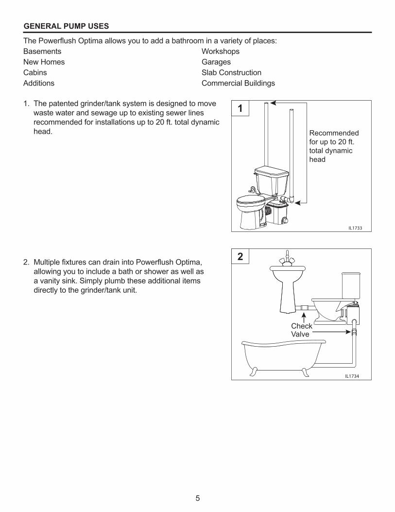
1. The patented grinder/tank system is designed to move waste water and sewage up to existing sewer lines recommended for installations up to 20 ft. total dynamic head. Recommended
for up to 20 ft.total dynamic head
IL1733
2. Multiple fixtures can drain into Powerflush Optima, allowing you to include a bath or shower as well as a vanity sink. Simply plumb these additional items directly to the grinder/tank unit.
IL1734
CheckValve
1
2

6
IL1731Optional Extension Kit 023260
Grinder/TankUnit
Wall
4. Hidden Installation (grinder/tank unit is hidden behind wall). For installation behind a wall, extension kit 023260 (sold separately) is required.
4
GENERAL PUMP USES
IL1730
3. Exposed Installation (grinder/tank unit is visible behind toilet).
This grinder/tank system can be used in the following installations:
3

7
IL1731Optional Extension Kit 023260
Grinder/TankUnit
Wall
IL1732
Level to within 1/8 in.
Power cord
LOCATION SELECTION AND LEVELING OF TANK
NOTE: If grinder/tank unit wlll be hidden behind a wall, be sure to allow access to the pump & switch after installation.
1. Select a location which is readily accessible to the existing discharge and vent lines. Installation behind a wall will require extension kit 023260 (sold separately).
1
2. Level grinder/tank unit to within 1/8 in. for length and width. Use hydraulic cement or similar material for leveling.
CAUTION: Do not use wooden shims to level tank. CAUTION: Ensure that nails, screws or other sharp
objects do not puncture tank
2
DIMENSIONS
17-1/2 in.
Dim A.14-3/8 in.
20 in.
All dimensions are in inches.
Dim A:S1201 Round Bowl = 29 in.S1202 Elongated Bowl = 31.5 in.
8
TOILET ASSEMBLY
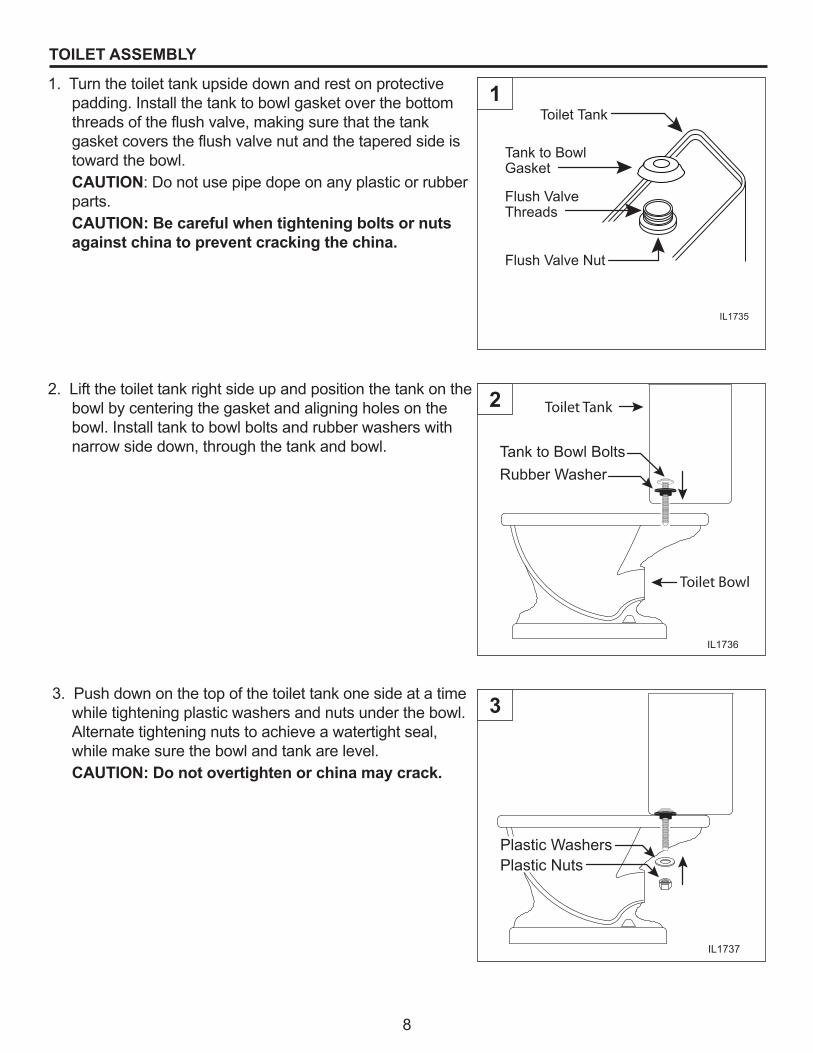
1. Turn the toilet tank upside down and rest on protective padding. Install the tank to bowl gasket over the bottom threads of the flush valve, making sure that the tank gasket covers the flush valve nut and the tapered side is toward the bowl.
CAUTION: Do not use pipe dope on any plastic or rubber parts.
CAUTION: Be careful when tightening bolts or nuts against china to prevent cracking the china.
2. Lift the toilet tank right side up and position the tank on the bowl by centering the gasket and aligning holes on the bowl. Install tank to bowl bolts and rubber washers with narrow side down, through the tank and bowl.
3. Push down on the top of the toilet tank one side at a time while tightening plastic washers and nuts under the bowl. Alternate tightening nuts to achieve a watertight seal, while make sure the bowl and tank are level.
CAUTION: Do not overtighten or china may crack.
Tank to BowlGasket
Flush ValveThreads
Flush Valve Nut
Toilet Tank
IL1735
1
Tank to Bowl BoltsRubber Washer
IL1736
Toilet Tank
Toilet Bowl
2
Plastic WashersPlastic Nuts
IL1737
3

9
IL1763
Item Description1 Toilet tank cover2 Toilet tank3 Toilet tank to toilet bowl gasket bolts4 Rubber toilet tank to toilet bowl gasket5 Water supply connection6 Water supply line rubber seal7 Water supply line adapter8 Water supply line (not included)9 Plastic flat washer10 Plastic nut11 Bolt cover12 Toilet bowl
TOILET ASSEMBLY
WATER SUPPLY HOOKUP
1. Make sure the incoming water supply is turned off.
Water SupplyShut-off Valve
1
2. Insert the plastic coupling wing nut, plastic washer and rubber seal over the end of the water supply line (not included).
Water Supply Line(Not Included)
Plastic CouplingWIng Nut
RubberSeal
PlasticWasher
IL1738
2

10
1. Position the grinder/tank unit a minimum of 1/8" from the wall with the inlet facing forward. Attach the rubber coupling to the inlet using the worm drive clamp provided.
IL1740Inlet
Wall
Grinder Pump Unit
1/8 in.Minimum
RubberCoupling
Clamp
3. Connect the water supply line to the ballcock shank that extends below the toilet tank by tightening the plastic adapter with rubber washer over the end of the ballcock shank.
CAUTION: Do not overtighten. Ballcock shank may split and void the warranty.
WATER SUPPLY HOOKUP
Ballcock
ToiletTank
Rubber Washer
Plastic Adapter
IL1739
2. Place the toilet in front of grinder/tank unit; aligning the discharge of the toilet with the inlet of the grinder/tank unit. Check to be sure that the rubber coupling will bridge the gap adequately for final installation. The toilet tank should be a minimum of 1/2 in. from the wall.
CAUTION: Do not connect rubber coupling to toilet at this time.
IL1741
GrinderUnit Inlet
Toilet Discharge
1/2 in. MinimumWall
3
1
2
EXPOSED PUMP UNIT INSTALLATION

11
EXPOSED PUMP UNIT INSTALLATION
3. Lightly mark the locations of the grinder/tank unit, toilet and closet screw set locations on the floor.
Grinder Pump Unit Location
ClosetScrew SetLocations
3
4. Lightly mark the wall with the height of the grinder/tank unit and the bottom and sides of the toilet tank to prevent interference from pipe runs during pipe installation. Remove the toilet from the grinder/tank unit and set it aside until piping is installed.
Grinder/tank unit
Toilet Tank Bottom and Sides
IL1743
4

12
NOTE: Installing the grinder/tank unit behind a wall will require an extension kit (P/N 023260) sold separately.
1. Place the toilet assembly a minimum of 1/2" from the wall and mark the closet screw set locations on the floor.
Grinder/tank unit
Toilet Tank Bottom and Sides
IL1743
HIDDEN PUMP UNIT INSTALLATION
2. Position the grinder/tank unit behind the wall. Measure the appropriate length of 3½ in. Schedule 40 PVC pipe provided with the extension kit and cut it to length. Set toilet aside.
CAUTION: Toilet assembly is top heavy. Take special precautions to ensure that toilet does not tip over and break.
IL1744
Grinder/tank unit
Sched 40PVC Pipe
1
2

13
1. Cut and dry-fit the pipe and fittings as required for 1" diameter discharge pipe (may be reduced to 3/4" diameter if codes permit). While dry-fitting the discharge pipe, position and mark the location of the grinder/tank unit discharge fitting.
PIPING
2. Cut and dry-fit 1-1/2 in. vent pipe as required to ensure that the vent pipe does not interfere with other components. Make the connection to the grinder/tank unit with the provided street elbow.
CAUTION: Proper venting is required for the toilet to flush. Do not use a mechanical type vent.
3. A 2 in. x 1 in. 90° discharge fitting and a 1-1/2 in. street elbow vent fitting have been provided for space constraints in an exposed configuration. However, these are not required for a hidden (behind a wall) installation. On a hidden installation, simplify installation and improve performance by replacing the 90° discharge fitting with a straight discharge pipe instead. Use a 2 in. straight coupling and reduce it down to 1 in.
1 in. DischargePipe and Fittings
IL1745
Grinder/tank unitdischarge fitting
IL1746
DischargePipe Vent Pipe
StreetElbow
IL1747
1 in.DischargePipe2 in.
Coupling
1
2
3
14
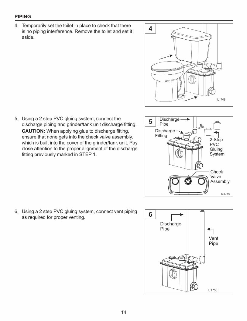
4. Temporarily set the toilet in place to check that there is no piping interference. Remove the toilet and set it aside.
5. Using a 2 step PVC gluing system, connect the discharge piping and grinder/tank unit discharge fitting.
CAUTION: When applying glue to discharge fitting, ensure that none gets into the check valve assembly, which is built into the cover of the grinder/tank unit. Pay close attention to the proper alignment of the discharge fitting previously marked in STEP 1.
6. Using a 2 step PVC gluing system, connect vent piping as required for proper venting.
PIPING
IL1748
IL1749
2-Step PVCGluing System
Check Valve Assembly
DischargeFitting
DischargePipe
IL1750
VentPipe
DischargePipe
4
5
6

15
TOILET INSTALLATION
1. Pre-drill holes for closet screw sets at the points marked earlier and install screws in holes.
Grinder/tank unit location
ClosetScrew SetLocations
IL1751
ToiletLocation
3. For exposed installation, Install rubber coupling onto the toilet discharge and grinder/tank unit hub and secure with the worm clamps provided .
2. Place the toilet assembly over the closet screw sets. Install the anchoring hardware and tighten in an alternating pattern. Check for level and shim as required. Be careful when tightening bolts or nuts against china to avoid cracking the china.
IL1748 Closet Screw Sets
IL1753
Grinder/tank unit Inlet
Toilet Discharge
Rubber coupling
Clamps
1
2
3

16
5. Install the water supply line from the existing water shut-off valve to the toilet water supply connection.
6. Open the water supply valve and check for leaks. The toilet tank should fill to the proper level. Adjust if required.
TOILET INSTALLATION
4. For hidden installation, (using optional extension kit 023260) install the rubber couplings to both the grinder/tank unit and the toilet discharge and secure to extension pipe with worm clamps provided.
IL1754
Grinder/tank unit
Sched 40PVC Pipe
Clamps
Couplings
Ballcock
ToiletTank
Rubber Washer
Plastic Adapter
IL1739
Water SupplyShut-off Valve
4
5
6
17
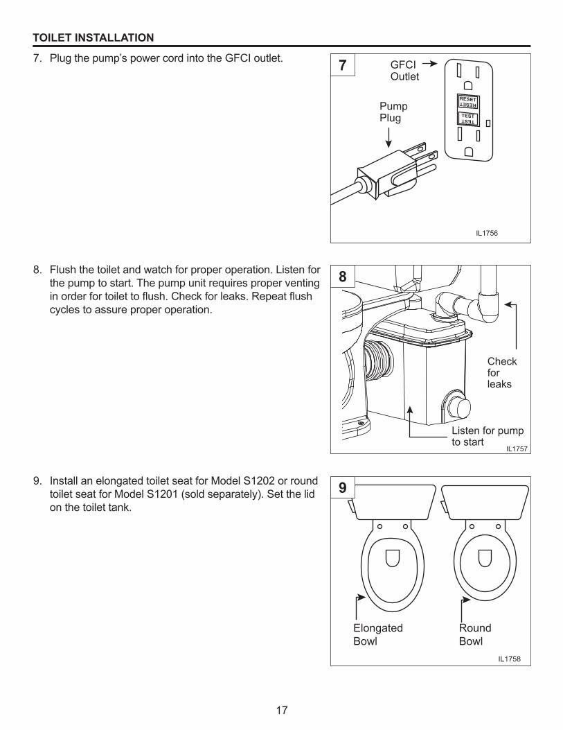
8. Flush the toilet and watch for proper operation. Listen for the pump to start. The pump unit requires proper venting in order for toilet to flush. Check for leaks. Repeat flush cycles to assure proper operation.
7. Plug the pump’s power cord into the GFCI outlet.
TOILET INSTALLATION
RESETRESET
TESTTEST
IL1756
PumpPlug
GFCIOutlet
Checkforleaks
Listen for pump to start
IL1757
9. Install an elongated toilet seat for Model S1202 or round toilet seat for Model S1201 (sold separately). Set the lid on the toilet tank.
RoundBowl
ElongatedBowl
IL1758
7
8
9

18
1. PowerFlush Optima is designed to accept additional bathroom fixtures utilizing the two side inlets.
ADDING OTHER BATHROOM FIXTURES
2. Additional fixtures can be attached either to the 2 in. MPT (outside diameter) or the 1½ in. slip (inside diameter). These side inlets are sealed by the factory to prevent leaks when inlets are not used. Before use, these side inlets must be drilled out using a 1¾ in. hole saw.
3. When utilizing side inlets, install a check valve on the incoming line.
IL1759
Tub
Sink
Grinder PumpUnit SideInlets
Drill Point
1-1/2" Slip Inside
2" MPT Outside
IL1760
IL1761
CheckValve
1
2
3

19
TYPICAL INSTALLATION
NOTE: All installations must comply with all applicable Electrical and Plumbing Codes, including, but not limited, to National Electrical Code; Local; Regional and/or State Plumbing Codes, etc.
8 Ft. Ceiling
7 Ft. Ceiling
Sub Floor 3/4” ThickMinimum
2 x 8 Floor Joists
8”Min
20
TROUBLESHOOTING
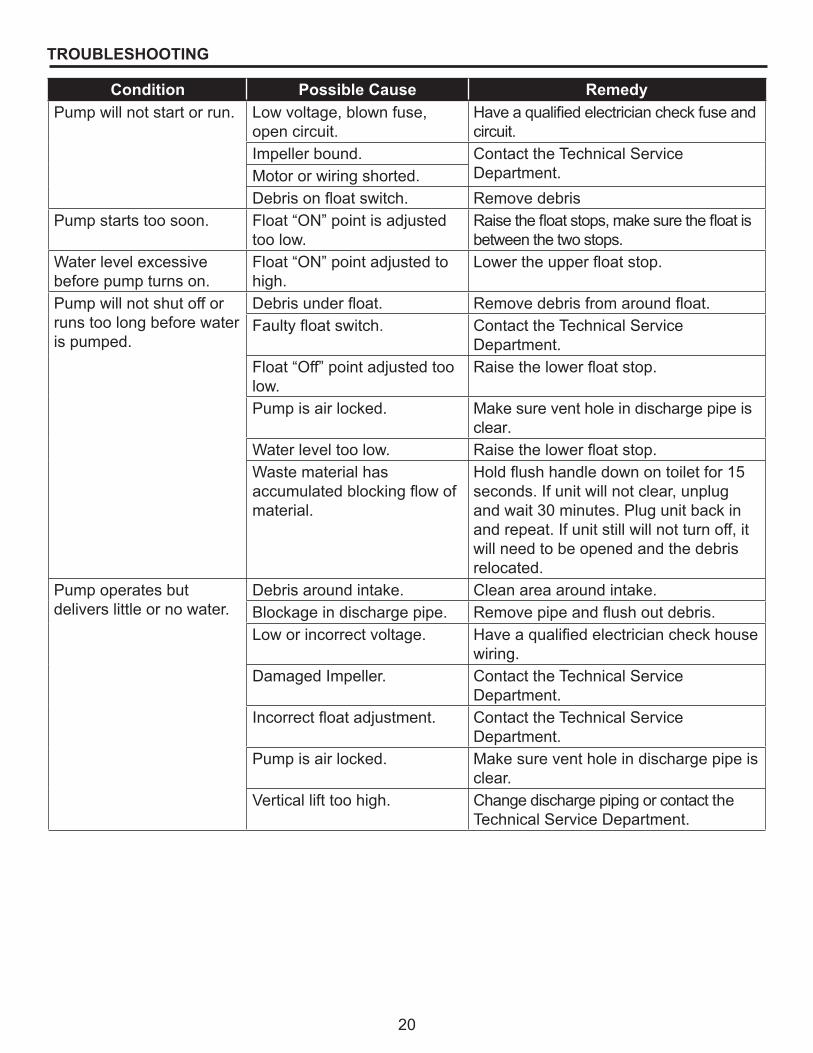
Condition Possible Cause RemedyPump will not start or run. Low voltage, blown fuse,
open circuit.Have a qualified electrician check fuse and circuit.
Impeller bound. Contact the Technical Service Department.Motor or wiring shorted.
Debris on float switch. Remove debrisPump starts too soon. Float “ON” point is adjusted
too low.Raise the float stops, make sure the float is between the two stops.
Water level excessive before pump turns on.
Float “ON” point adjusted to high.
Lower the upper float stop.
Pump will not shut off or runs too long before water is pumped.
Debris under float. Remove debris from around float.Faulty float switch. Contact the Technical Service
Department.Float “Off” point adjusted too low.
Raise the lower float stop.
Pump is air locked. Make sure vent hole in discharge pipe is clear.
Water level too low. Raise the lower float stop.Waste material has accumulated blocking flow of material.
Hold flush handle down on toilet for 15 seconds. If unit will not clear, unplug and wait 30 minutes. Plug unit back in and repeat. If unit still will not turn off, it will need to be opened and the debris relocated.
Pump operates but delivers little or no water.
Debris around intake. Clean area around intake.Blockage in discharge pipe. Remove pipe and flush out debris.Low or incorrect voltage. Have a qualified electrician check house
wiring.Damaged Impeller. Contact the Technical Service
Department.Incorrect float adjustment. Contact the Technical Service
Department.Pump is air locked. Make sure vent hole in discharge pipe is
clear.Vertical lift too high. Change discharge piping or contact the
Technical Service Department.

21
Manufacturer warrants, to the purchaser and subsequent owner during the warranty period, every new product to be free from defects in material and workmanship under normal use and service, when properly used and maintained, for a period of one year from date of purchase by the end user, or 18 months from date of original manufacture of the product, whichever comes first. Parts that fail within the warranty period, one year from date of purchase by the end user, or 18 months from the date of original manufacture of the product, whichever comes first, that inspections determine to be defective in material or workmanship, will be repaired, replaced or remanufactured at Manufacturer’s option, provided however, that by so doing we will not be obligated to replace an entire assembly, the entire mechanism or the complete unit. No allowance will be made for shipping charges, damages, labor or other charges that may occur due to product failure, repair or replacement.
This warranty does not apply to and there shall be no warranty for any material or product that has been disassembled without prior approval of Manufacturer, subjected to misuse, misapplication, neglect, alteration, accident or act of God; that has not been installed, operated or maintained in accordance with Manufacturer’s installation instructions; that has been exposed to outside substances including but not limited to the following: sand, gravel, cement, mud, tar, hydrocarbons, hydrocarbon derivatives (oil, gasoline, solvents, etc.), or other abrasive or corrosive substances, wash towels or feminine sanitary products, etc. in all pumping applications. The warranty set out in the paragraph above is in lieu of all other warranties expressed or implied; and we do not authorize any representative or other person to assume for us any other liability in connection with our products.
Contact Manufacturer at, 95 North Oak Street, Kendallville, IN 46755, Attention: Customer Service Department to obtain any needed repair or replacement of part(s) or additional information pertaining to our warranty.
MANUFACTURER EXPRESSLY DISCLAIMS LIABILITY FOR SPECIAL, CONSEQUENTIAL OR INCIDENTAL DAMAGES OR BREACH OF EXPRESSED OR IMPLIED WARRANTY; AND ANY IMPLIED WARRANTY OF FITNESS FOR A PARTICULAR PURPOSE AND OF MERCHANTABILITY SHALL BE LIMITED TO THE DURATION OF THE EXPRESSED WARRANTY.
Some states do not allow limitations on the duration of an implied warranty, so the above limitation may not apply to you. Some states do not allow the exclusion or limitation of incidental or consequential damages, so the above limitation or exclusion may not apply to you.
This warranty gives you specific legal rights and you may also have other rights which vary from state to state.
WARRANTY
22
IL1765
2
3
4
5
6
7
10
8
9
12
13
14
1516
11
16
1202-A(Piggyback Float Style)
1202-B (Float Rod Kit)
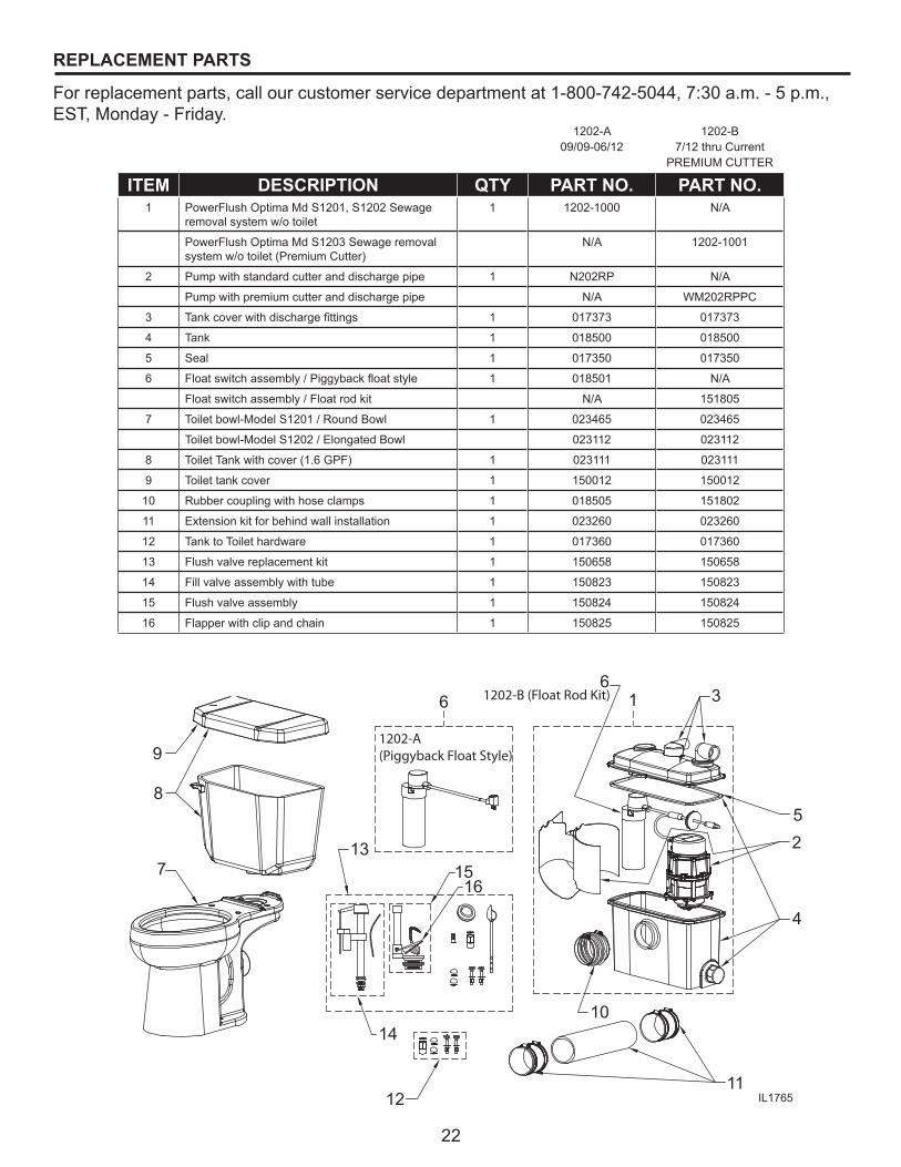
REPLACEMENT PARTS
For replacement parts, call our customer service department at 1-800-742-5044, 7:30 a.m. - 5 p.m., EST, Monday - Friday.
1202-A09/09-06/12
1202-B7/12 thru Current
PREMIUM CUTTER
ITEM DESCRIPTION QTY PART NO. PART NO.1 PowerFlush Optima Md S1201, S1202 Sewage
removal system w/o toilet1 1202-1000 N/A
PowerFlush Optima Md S1203 Sewage removal system w/o toilet (Premium Cutter)
N/A 1202-1001
2 Pump with standard cutter and discharge pipe 1 N202RP N/A
Pump with premium cutter and discharge pipe N/A WM202RPPC
3 Tank cover with discharge fittings 1 017373 017373
4 Tank 1 018500 018500
5 Seal 1 017350 017350
6 Float switch assembly / Piggyback float style 1 018501 N/A
Float switch assembly / Float rod kit N/A 151805
7 Toilet bowl-Model S1201 / Round Bowl 1 023465 023465
Toilet bowl-Model S1202 / Elongated Bowl 023112 023112
8 Toilet Tank with cover (1.6 GPF) 1 023111 023111
9 Toilet tank cover 1 150012 150012
10 Rubber coupling with hose clamps 1 018505 151802
11 Extension kit for behind wall installation 1 023260 023260
12 Tank to Toilet hardware 1 017360 017360
13 Flush valve replacement kit 1 150658 150658
14 Fill valve assembly with tube 1 150823 150823
15 Flush valve assembly 1 150824 150824
16 Flapper with clip and chain 1 150825 150825


![NORTA MIT PRESENTATION.pptx [Read-Only] · • Centrifugal pumps • Side channel pumps • Gear pumps • Screw pumps • Single screw pumps • Piston pumps • Vacuum pumps •](https://img.pdfslide.net/doc/110x75/5ec27ab9e3ef591d10504c3a/norta-mit-read-only-a-centrifugal-pumps-a-side-channel-pumps-a-gear-pumps.jpg)