Embed Size (px)
Citation preview
Stark Pool Controller Operator's Manual Rev 4 March 18, 1998

Table of Contents Page Functional Overview ...................................................................... 2 Backwash Operation Details ............................................. 3 Energy Saver Details .......................................................... 4 Watchman Details .............................................................. 4 General Operation ............................................................................... 5 System Configuration ............................................................. 6 Set Time and Date ........................................................ 7 Set Backwash Parameters ................................................ 8 Backwash Time ......................................................... 8 Interfilter Delay ......................................................... 8 Surge Delay ................................................................ 8 Firemans Delay ......................................................... 9 Aux 4 Output Delay .................................................. 9 Aux 4 Duration ......................................................... 9 Number of Filters ..................................................... 9 Pump Suspend Mode ................................................ 9 Reset Backwash Counter ........................................... 10 Set Display Parameters .................................................. 10 Display Timeout ....................................................... 10 English/Metric Units ................................................. 10 Set Energy Saver Parameters .......................................... 11 System Utilities .................................................................... 12 Sensor Calibration ........................................................ 12 Alarm Configuration ................................................... 14 Alarm Enable/Disable ............................................. 14 Temperature Alarm Limits ......................................... 15 Flow Switch Alarm ................................................. 15 Manual Operations ....................................................... 16 Manual or Automatic Operation .................................. 16 Pump or Heater On/Off ........................................... 16 Manual Backwash .................................................. 17 Select Backwash Mode ............................................................ 18 Time Interval Mode ........................................................ 18 Differential Pressure Mode .......................................... 19 Flow Rate Mode ............................................................... 20 Volume Mode ................................................................... 21 Time of Day Mode ........................................................ 22 Time or Pressure Mode ................................................. 23 Time and Pressure Mode .............................................. 23 Volume or Pressure Mode ........................................... 24 Volume and Pressure Mode ....................................... 24 Time of Day and Pressure Mode .................................. 24 Installation and Service ........................................................................ 25 Special Configurations ......................................................... Appendix A Field Wiring Diagrams ......................................................... Appendix B System Hardware Specifications ............................................ Appendix C
Page 1

Functional Overview The Stark Pool Control System is designed to automatically manage pools for maximum economy and minimum maintenance. This system consists of the Stark Controller, with its associated temperature, pressure and flow sensors, and the Multiport Valve which is used to switch filters in and out of backwash (see Appendix A for optional configurations).. The Stark Pool Control System continuously monitors filter inlet pressure, outlet pressure, elapsed time since last backwash, and time of day (flow rate can also be monitored with optional flow sensor), to determine when a backwash operation is necessary. The controller can perform automatic filter backwash operations on systems containing up to 11 filters. Additional features provide comprehensive performance benefits and cost savings for a wide range of applications: - An Energy Saver feature can be used to shut down the system pump and heater on a seven day
programmable cycle. This feature can reduce energy costs and prevent wear on equipment when the pool is not in use.
- A Water Saver feature can be used in conjunction with a backwash settling sump to recycle backwash
water for a substantial reduction in water usage. - The Chemical Saver feature will automatically turn off chemical feed during backwash operations to
reduce loss of chemicals. - The Watchman feature can be used to monitor filtration system performance, effluent flow and pool
temperature. The Alarm output can be optionally used to shut down the pool pump and heater, energize a local alarm indicator, or even telephone maintenance personnel (with optional dialer).
- Four auxiliary outputs and two auxiliary inputs can be used to monitor and control air bump pumps, peak
load pumps, make-up water valves and other pool equipment to improve pool performance and efficiency. - A RS-232-C Serial Interface is included to provide access to all system operations from a host computer.
This computer can be located up to 50 feet away with a standard RS-232 cable, up to 1000 feet away with optional RS-422 converters, or any distance with optional telephone modem. With modem operation, multiple pool locations can be controlled from one central location.
- Custom programming services are available to adapt the controller for special needs.
Page 2

Backwash Operation Details The controller can be instructed to perform a backwash of up to 11 filters based on any one of the following ten conditions: 1) Time Interval 2) Pressure Differential 3) Flow Rate 4) Volume 5) Time or Pressure 6) Time and Pressure 7) Volume or Pressure 8) Volume and Pressure 9) Time of day 10) Time of day and Pressure When prevailing conditions call for a backwash cycle, the controller performs the following sequence of operations: - First, the controller energizes the “Master” relay (Auxiliary Output 1) which is intended to signal other
devices such as ozone and chemical controllers that a backwash is in process. - Next, the controller instructs the multiport valve to switch the first filter into its backwash configuration.
(when moving the multiport valve, the controller waits an additional 60 seconds for the hydraulic valves to switch to their new positions).
- The controller then turns on Auxiliary Output 3. Possible uses for this output might be to close a solenoid
actuated priority valve (if one is required on the system) or to disable make-up water fill systems during backwash operations.
- After a 1 minute waiting period, Auxiliary Output 2 is turned on. One possible use for this output is to turn
on air bump pumps to help rejuvenate filter sand. - The controller then waits for a user specified period of time for the filter to backwash ("Backwash
Duration"). - Auxiliary Outputs 2 and 3 are then turned off and the controller instructs the multiport valve to suspend
backwash operations (waiting 60 seconds for the hydraulic valves to finish shifting) and then waits for a user selected time interval ("Interfilter Delay") before moving to the next filter.
- The multiport valve then switches to the next filter. This cycle is repeated for each filter in the system. After all filters have been backwashed, the controller moves the multiport valve to the “Home” position and turns the Master relay (Auxiliary Output 1) off. After an additional valve shift delay of 60 seconds, the controller waits for a user specified waiting period (Aux 4 delay) and then turns on Auxiliary Output 4 for a selected time interval (Aux 4 duration). This output might be used to control a pump in a settling sump to recycle backwash water. After this entire sequence of events has been completed, the controller waits until conditions once again call for a backwash. An alternative cycle is available for pools where the pump and heater must be turning off during backwash operations (see "Backwash Parameters, Backwash 3" section of the manual).
Page 3

Energy Saver Details In addition to managing backwash operations, the controller can shut down the pool heater and pump automatically when the pool is not in use. This can reduce energy costs as well as extending the life of these expensive components. The Energy Saver Cycle can be programmed to occur once per day for each of the seven days of the week. When the real time clock indicates the start of an Energy Saver Cycle, the controller turns off the power to the pool heater and then waits a user specified amount of time ("Fireman Delay") before removing power to the pumps. This reduces thermal stresses on the heater by insuring a constant flow of water until residual heat has been dissipated. Watchman Details The controller automatically monitors valves and sensors in the pumping system to insure that excess water is not consumed in the backwash process. A watchdog timer is initialized at the beginning of a backwash cycle and an alarm output is activated if system backwash does not complete on time. In addition, an auxiliary switch input can be connected to a On/Off type flow switch in the backwash discharge pipe. If this switch indicates backwash discharge after the system has completed all of its backwash operations (possible result of a failed valve) the alarm output is activated, pump and heater are turned off and filter operation is suspended. If a backwash cycle has been requested based on differential pressure across the filter system or on flow rate, and three consecutive backwash operations have not succeeded in bringing the pressure or flow rate back into acceptable ranges, the alarm is activated and filter operation is suspended. Limits can also be imposed upon water temperature to energize the alarm if problems arise in the heating system. For the temperature alarm, the alarm output is activated, but filter operation is not suspended. The alarm output can be used to activate a local alarm indicator such as a flashing light or a bell, or can be used to signal an automatic dialer (optional) to automatically phone off-site maintenance personnel.
Page 4

General Operation With the controller properly installed and powered, system status should be displayed (see figure 1).
A
B
C
D
24
MTIME
COUNT
NXT BWASH10:00 PM 8:00 AM
GPMDEG FTEMP
GALFLOW
DELTAOUTLETINLET
AMONDAY
OPERATION IS AUTOMATICALARM IS ENABLED
E SAVER
OFF SUN
VOLUME
PSI 15 9PSI PSI
83 375 12750
12
11:12
FILTER
ALARM
PUMP
SAVER
BACKWASH
ENERGY
97 8
64 5
31 2
MENU HELP0
Figure 1, Status Display
Included on this display is real time information on system parameters including inlet and outlet pressure, temperature, flow, and volume of water filtered since the last backwash operation. System status is also presented on this screen and includes information on the next scheduled backwash, the present time, and the next scheduled energy saver event. Messages along the bottom of the display indicate whether the system has automatic control of the pool or whether backwash operations must be initiated manually. Also indicated is whether the alarm is presently enabled or disabled. These messages are replaced by backwash cycle information when a backwash is in progress. In the lower right hand corner is a count of the number of backwash cycles that has occurred since the last system reset. Operator interaction with the system is accomplished through the use of the four soft keys to the right of the display labeled A, B, C and D, and with the 12 key keypad below and to the right of the display containing the keys 0-9, HELP and MENU. The HELP key can be pressed at any time to display on-line information that describes choices available from the present screen. These help screens contain most of the information found in subsequent pages of this manual.
Page 5

A
B
C
D
MAIN MENU
DISPLAYSTATUS
FUNCTION.TO PROGRAM DESIREDPRESS A, B, OR C
STATUS DISPLAYPRESS D FOR
UTILSSYSTEM
SYSTEMPARAMS
SELECTOP MODE
Figure 2, Main Menu
From the main status screen, any key can be pressed to display the main menu (see figure 2). This menu prompts the operator through the steps necessary to select desired operating modes, set desired set points, and calibrate system sensors. Non-numeric data is entered through the use of the four keys located along the right of the display ( A, B, C, and D). The function of these "soft" keys changes from menu to menu and is indicated in the rightmost columns of the current display. Numeric data is entered through the use of the ten numeric keys (0-9). To change a system parameter, use the soft keys to select the item that you wish to change, then use the numeric keys to enter the new value. If the system is left in the middle of data entry, it will automatically return to the status display and resume normal operation after a time-out period of five minutes. The status display can also be restored by pressing "MENU" to return to the main menu, and then pressing "D" for "Display Status". System Configuration The controller must be configured to meet the specific requirements of each pool pump and filtration system. Two levels of configuration are available. Level 1 configuration involves decisions that are made at the time of installation such as which type of valves are used to switch filters in and out of backwash and what size piping is used. This configuration should be done by the installer. Information on level 1 configuration can be found in the “Installer’s Manual”. Depending on what functions are selected by the installer, some functions described in this manual may not function as described. Please see Appendix A for a description of these differences. Level 2 configuration involves decisions that can be made from time to time after a system has been installed to adjust to changing conditions or pool usage patterns. These decisions include the setting of the system clock, changing of parameters directing the length and timing of the backwash cycle, and instructing the controller as to the pool hours of operation. From the main menu, press "B" for "System Parameters". The System Parameters menu will be displayed (see figure 3) presenting four categories of parameters that require configuration before proper pool operation can be expected. The four "soft" keys can be used to select the different categories.
A
B
C
D
SET SYSTEM
DISPLAYPARAMS
DESIRED FUNCTION.OR D TO SELECTPRESS A, B, C
FOR MAIN MENUPRESS MENU KEY
SAVERENERGY
BCKWSHPARAMS
TIME/DATEPARAMETERS
Figure 3, Set System Parameters
Key "A" or "Time/Date" is used to set the system clock. This clock consists of Hours:Minutes, AM/PM, Day of the week, Month, and day of the month. The time is displayed on the status screen. Time of day and day of the week are used for the "Time of Day" backwash operating mode and for the "Energy Saver" feature (if programmed). Key "B" can be pressed to select "Backwash Parameters". This selection contains a series of screens that allow the user to set time intervals that are used in the filter system backwash sequence. These parameters include backwash duration, interfilter delay, pressure surge delay, firemans delay, and auxiliary output 4 timing.
"Bckwsh Params" also contains screens to set the number of filters that are being used in the system, whether the heater should be shut off during backwash operations (pump suspend mode), and whether pool
Page 6

parameters should be displayed in english or metric units of measure. Lastly, this section contains a screen to reset the backwash counter to 0. "Energy Saver" is used to set a seven day schedule of appropriate times for shutting down the heater and pump to save energy. Set Time and Date The time of day and day of the week are important parameters to the Stark Controller. These parameters are used to initiate the "TIME OF DAY" mode of backwash operation and are also used to automatically enter and exit the "ENERGY SAVER" function. Once set, all time and date values are updated automatically by the system. In the event of power failure, these parameters continue to be updated by battery operated circuitry to insure that the system will still know the correct time and date upon the resumption of power. In normal operation, these clock batteries are continually charged to insure that they will be ready to provide backup if the system power fails. If power has been interrupted from the system for a period of months, the clock batteries may have been drained and allowed the time and date information to be lost. Upon installation of a new Stark Controller, the time and date parameters should always be checked and set if required.
AM/PM
A
B
C
DENTER
MP
OR PM.THEN SELECT AMUSING NUMBER KEYS.ENTER DESIRED TIME
SET TIME
1:57
SAVE NEW TIME.PRESS ENTER TO
CLEAR
Figure 4, Set Time Screen
To set time and date parameters, select "SET SYSTEM PARAMETERS" from the main menu, then press "A" to select TIME/DATE. The "SET TIME" screen will be displayed (see figure 4). Enter the correct time in 12 hour format using the number keys. Then press "B" to select am or pm. If a mistake is made, press "C" to clear the time field, and try entering the correct time again. Once the time is displayed as you would like it entered in the system clock, press "D" to save the new time. If you choose to exit this screen without changing the old time, you may press the "MENU" key to return to the "SET SYSTEM PARAMETERS" screen. When you press "D" to enter a new time value, you will be presented with the "SET DATE" screen (see figure 5). This screen is used for setting both the day of the week (Monday, Tuesday, etc.), the month (January, February, etc.), and the day of the month. Although the Month and day of the month information are not used by the Stark Controller at present, these values are updated automatically and can be set if desired.
A
B
C
D
SET DATE
ENTER
TUESDAY
JULY 26
WITH NUMBER KEYS.MONTH; ENTER DATEUSE B TO ADVANCEDAY OF THE WEEK;USE A TO ADVANCE
SAVE NEW DATE.PRESS ENTER TO
ESCAPE
ADV.MONTH
ADV.DAY
Figure 5, Set Date
To enter the current date, first press "A" to advance the displayed day of the week to the current day. Next, press "B" to advance the displayed month to the correct month. Finally, use the number keys to enter the correct day of the month. If a mistake is made in entering the day of the month, enter a couple of zeros to clear the field, then try again. Once the displayed date is correct, press "D" to save the new day and date information. If you choose to exit this screen without changing the old values, press "C" for Escape. You will be returned to the "SET SYSTEM PARAMETERS" screen.
Page 7

A
B
C
D
BACKWASH PRMS
PAGE 4 SELECTS
PAGE4
BACKWASH COUNTER
PUMP MODE NO. OF FILTERSPAGE 3 SELECTS
AUX4 TIMING FIREMANS DELAYPAGE 2 SELECTS
SURGE DELAY BACKWASH TIMINGPAGE 1 SELECTS
USE MENU KEY TO EXIT
3PAGE
PAGE2
PAGE1
Figure 6, Backwash Parameters
Set Backwash Parameters Before a backwash operation can be successfully executed, Parameters associated with the particular pool installation must be entered into the controller. This is accomplished through four pages of backwash parameter screens. To enter these installation specific parameters, return to the "SET SYSTEM PARAMETERS" screen and press "B" for "BCKWSH PARAMS" (see figure 6). An index of the four pages of parameters is displayed. If the system is being set up for the first time, all four pages should be accessed and all parameters set before the system is put on-line. Select page 1 of the "BACKWASH PRMS" screen by pressing the "A" key. A new screen will be presented to allow system values to be entered or changed (see figure 7).
A
B
C
D
BACKWASH 1
SURGE DELAY
ENTER
SEC.
1
<
INTERFILTER DELAY
SEC.120BACKWASH DURATION
D TO ADVANCE TO NEXT FIELD.DESIRED VALUE, THEN PRESSUSE NUMBER KEYS TO ENTER
MIN.
30
Figure 7, Backwash 1
Notice the "<" to the right of the Backwash Duration field. This indicates that the Backwash Duration field is currently selected. This field may now be modified with the number keys. To set a new value, enter a number between 0 and 9999 seconds (a reasonable starting value might be 120 seconds), then press "D" to save this new value and advance to the next field. The "D" key may also be used to advance to the next field without change to the current field. To advance to the next field, press "D" before any numeric entry is made. This allows the user to scroll to the desired field without modifying all preceding values.
The next field is labeled "Interfilter Delay". This is the amount of time that is waited between filters in a backwash cycle. This delay is provided to allow time to drain away effluent from a filter before the next filter is flushed. This time is in minutes, allowing up to 9999 minutes (about one week) between filters. Long interfilter delays are seldom necessary. For most applications, this delay should be set to 0 minutes. The last field on page 1 is "Surge Delay". This is the amount of time that pressure or flow limits must be exceeded before a decision is made to start a backwash cycle based on these parameters. This delay is necessary to allow for temporary excursions in pressure and flow that are unrelated to filter system performance. Values from 0 to 9999 seconds are acceptable, but typical values range from 10 seconds to 120 seconds. Upon pressing the "D" key to enter this last value, the controller returns to the "BACKWASH PRMS" screen. You may alternately return to the Backwash Parameters screen at any time by pressing the "MENU" key.
Page 8

Select page 2 of the Backwash Parameters screen by pressing key "B". The screen that you see pictured in Figure 8 will be displayed.
A
B
C
D
BACKWASH 2
AUX4 DURATION
ENTER
SEC.
30 SEC.
AUX4 OUTPUT DELAY
<SEC.
FIREMANS DELAY
15
D TO ADVANCE TO NEXT FIELD.DESIRED VALUES, THEN PRESSUSE NUMBER KEYS TO ENTER
60
Figure 8, Backwash 2
The first field on this page is labeled Firemans Delay. When the controller turns the pump off for any reason, it first turns the heater off. The controller then waits for the number of seconds (between 0 and 9999) that has been entered in this field before turning the pump off. This feature is included to minimize thermal stresses on the pool heater by insuring water flow through the heater until residual heat has sufficient time to dissipate. A 30 second time interval should be adequate for most heaters. If you do not desire to use this feature, set the Firemans Delay to 0 seconds.
After all filters in the system have been backwashed, the controller turns on the Auxiliary 4 Output. This output can be used to control pool equipment that is related to the backwash operation. One possible use of this output is to energize a pump that re-introduces backwash effluent into the pool system after it has settled in a settling sump. Aux 4 Delay is the number of seconds after a backwash cycle that is waited before the output is energized. This would be the settling time if used for a settling sump pump. Aux 4 Duration is the number of seconds that this output remains energized after each backwash cycle. The Auxiliary 4 Output function is considered by the controller to be part of the backwash cycle (even though normal filter operation has resumed before this function starts). Because of this, subsequent backwash cycles can not be started until Aux 4 has timed out. For this reason, if the Aux 4 output is not used, both Aux 4 Delay and Aux 4 Duration should be set to zero. Upon entry of this last field, the system will return to the Backwash Parameters screen. Alternately, the MENU key can be used at any time to return to the Backwash Parameters screen.
A
B
C
D
BACKWASH 3
ENTER
YESSHIFTING VALVETURN PUMP OFF WHILE
3NUMBER OF FILTERS
KEY B OR TOGGLE PUMP MODE WITH CINCREMENT NUMBER OF FILTERS WITH
PRESS MENU TO ESCAPE
MODEPUMP
NUM. OFFILTERS
Figure 9, Backwash 3
Select page 3 of the Backwash Parameters screen by pressing "C". The screen that you see in figure 9 will be presented. The first field in this selection requests information about the number of filters installed in the system. The controller can manage up to 4 filters if configured for solenoid valves (see Appendix A), 11 filters if configured for a standard Multiport valve, or 16 filters if an Electronic Multiport Interface and solenoid valves are installed. Press "B" (Number of Filters) as required to scroll to the correct number of filters for your system. Key "C" (Pump Mode) can be used to enable or disable the "Pump Suspend Mode" of backwash operation. In some installations, it is desirable to turn off the pump while the backwash control valve is switching from one filter to the next.
Page 9

If the "Pump Suspend Mode" is selected (by pressing key "C" to display "YES" after the "Turn Pump Off While Switching Valve" field), the controller will modify the backwash cycle to first turn off the heater, then wait for the "Firemans Delay" before turning on the “Master” relay and turning off the pump. The multiport valve then moves to the backwash position and the pump is turned on for the backwash duration. The pump is again turned off while the multiport valve is moved into the interfilter position. After a “valve shift delay”, the pump is turned back on for the “Interfilter Delay” period. If “Interfilter Delay” is set to 10 minutes or greater, the heater will be turned on for this period. If “Interfilter Delay” is set to less than 10 minutes, the heater remains off for the entire backwash cycle. At the end of the “Interfilter Delay”, if the heater was turned on, it is turned off and a “Firemans Delay” is executed before turning off the pump. Then the next filter is selected with the multiport valve and the cycle repeats until all filters are backwashed. At the end of the cycle, the multiport valve moves to the home position, waits a 60 second valve shift delay for all valves to return to their “filter” position, and then turns on the heater and pump to resume normal pool operation. At this time, the Aux 4 delay begins. When both of these fields are configured as desired, either press key "D" (enter) to save these new values and exit back to the "BACKWASH PRMS" screen, or press the MENU key to escape back to the Backwash Parameters screen without changing old values.
A
B
C
D
BACKWASH 4
BACKWASHES COMPLETED
EXIT
SINCE LAST RESET.
30
PRESS MENU.TO EXIT W/O CHANGE,
COUNTER, PRESS C.TO RESET BACKWASH
TO EXIT, PRESS D
RESET
Figure 10, Backwash 4
Select page 4 of the Backwash Parameters screen by pressing key "D" (see figure 10). The controller logs the number of backwash cycles that it has successfully completed (to a maximum of 9999). This information may be useful to help schedule maintenance. The count can be reset to 0 by pressing "C" (Reset). Exit this screen by pressing "D" (Exit) or MENU and you will be returned to the Backwash Parameters screen. From the Backwash Parameters screen, press MENU to exit to the Set System Parameters screen.
Set Display Parameters
A
B
C
D
DISPLAY PARAMETERS
ENTER
15 MINUTES
DISPLAY TIMEOUT PERIOD
PARAMETERS BETWEEN ENGLISH AND METRIC.USE KEY C TO TOGGLE DISPLAY OF PHYSICAL
DISABLES TIMEOUT. USE ENTER TO SAVE.BACKLIGHT TIMEOUT. A VALUE OF 0USE NUMERIC KEYS TO SET DISPLAY
ENGINEERING UNITS
ENGLISHPRESS MENU TO ESCAPE
UNITSENGR.
Figure 11, Display Parameters
From the "SET SYSTEM PARAMETERS" screen, press "C" for "DISPLAY PARAMS" and a screen providing display options will be displayed ( figure 11). The display light has a limited life. To conserve this backlight, the system can turn the light off when not needed. Use the numeric keys to enter a Display Timeout Period of up to 99 minutes. When any key is pressed, the controller will turn the backlight on and leave it on for this timeout period. Then the light will be turned off until a key press is again detected. If you do not wish to use the display timeout feature, select a timeout period of 0 and the light will remain on all of the time. Key "C" (Engr. Units) can be used to toggle between metric and english units of measure for pressure, flow, temperature, and volume. The selected system of units will be used for all data entry and display, system wide. Engr. Units can be changed at any time without re-entering affected set points. The system will automatically convert between units.
Page 10

Set Energy Saver Parameters The Energy Saver Cycle is a seven day programmable cycle that can be used to turn off the pool pump and heater for intervals of time when the pool is not in use. This cycle interacts with the backwash cycle in the following manner. If a backwash cycle is in progress when an energy saver cycle is programmed to start, the backwash is completed (including Aux 4 cycle) before the energy saver cycle is started. If very long backwash cycles are programmed, the energy saver cycle may be skipped entirely. Once the energy saver cycle is entered, the interval timer associated with backwash operations is put on hold and does not resume counting down until the energy saver cycle has ended. If a backwash cycle is tripped during an energy saver cycle (an example of this would be a backwash that is requested manually from the "Manual Operations" screens described next, or a "Time of Day" backwash where the time selected falls within an energy saver cycle), the backwash cycle will be held off until the energy saver cycle is over (i.e. it will be triggered, but will not execute until the energy saver cycle is through). If you wish to run the pool during a scheduled energy saver cycle, the pool can be switched to "MANUAL" and the pump and heater can be started from the "Manual Operations" screens. If this is done, remember that ALL automatic operations are suspended until the controller is switched back to "AUTOMATIC".
A
B
C
D
ENERGY SAVER
ENTER
POOL ON = 2:00 PM
POOL OFF = 1:00 PM
TIME OFF OR ONAND C TO SELECTOF THE WEEK, THEN BUSE A TO SELECT DAY
SUNDAY
USE M TO EXIT
AM/PM
SELECTFIELD
SELECTDAY
<
Figure 12, Energy Saver
Press "D" from the "Set System Parameters" menu. The screen in figure 12 will be displayed. The Energy Saver option must be program-med for each day of the week. One "Off" time and one "On" time must be selected for each day. The "Off" time may be earlier than, later than, or equal to the "On" time for that same day. If the "Off" time and "On" time are equal on a given day, no Energy Saver Cycle is scheduled for that day. If you wish to program a cycle that starts one day and ends the next (for example turning the heater off at night), pair the "Off" time from one day with the "On" time from the next.
To select the desired day of the week, press "A" for Select Day. The day of the week that is displayed below the "Pool Off" time advances one day for each press of the "A" key. When "Monday" is displayed, the displayed "On" and "Off" times reflect the current values programmed for Monday. To change these values, press "B" (Select Field) to move the cursor ("<") to the desired field. Then use the number keys to enter the desired time in 12 hour format. Lastly, use key "C" (Am/Pm) to toggle between AM and PM as required. When the correct time has been entered, you must press the "Enter" key to save this value into memory. After both the "Off" time and "On" time have been entered for the selected day, advance to the next day with the "A" (Select Day) key. Repeat this process for all seven days, then use the MENU key to exit to the Set System Parameters screen.
Page 11

System Utilities Press MENU to return to the Main Menu and then select "C" for System Utilities (see figure 13). From this menu, additional menus can be reached that will allow the operator direct access to all of the I/O capabilities of the controller.
A
B
C
D
SYSTEM UTIL.
EXIT
ALARM OR TO PROGRAMSELECT C TO DISABLE
SENSORS.CALIBRATE SYSTEMSELECT B TO
PUMP OR HEATER.BACKWASH OR TO RUNBACKWASH, TO DISABLESELECT A TO FORCE
ALARM CRITERIA.CONFIGALARM
SENSORCAL
MANUALOPS
Figure 13, System Utilities
By selecting "A" (Manual Operations) additional menus will be presented to allow the operator to manually control pool pumping, heating, and filtration components directly from the keyboard. This selection is also used to switch the pool from "AUTOMATIC" to "MANUAL" operation as desired. Select "B" (Sensor Calibration) to set temperature, pressure and flow calibration factors. Select "C" (Alarm Configure), to configure the alarm to automatically monitor backwash operations and pool temperature. This selection is also used to reset the alarm after it has been tripped. Sensor Calibration When a new system is started up for the first time, the sensors measuring pressure, temperature and flow may need to be calibrated. From the System Utilities menu, select "B" for Sensor Calibration. The "SENSOR CALIBRATION" menu will be presented that allows you to select one of four sensors for calibration (figure 14).
A
B
C
D
SENSOR
FLOWRATE
PARAMETERS.TO AGREE WITH ACTUAL PHYSICALADJUST SYSTEM SENSOR READINGS
CALIBRATION
PRESS M TO EXIT
TEMP
OUTLETPRESS
INLETPRESS
Figure 14, Sensor Calibration
With the Stark Controller, pressure and temperature sensor scaling is accomplished through software calculations based on two known measurement values, one toward the high end of the expected range of measurement ("HI Cal") and one toward the low end ("LO Cal"). Interpolation techniques are used to calculate readings for all measured values from these two reference points. On Inlet and Outlet pressures, both HI and LO values can be set. On Temperature, the LO value is set at the factory and should not need field adjustment, but the HI value can be set from the calibration screens.
Press the soft key associated with the sensor that you wish to calibrate. Following is a discussion of inlet pressure sensor calibration. Outlet pressure and temperature calibrate similarly.
Page 12

A
B
C
D
INLET PRESSURE CAL.
ENTER
CURRENT SENSOR = 150
PRESS D TO SAVE NEW VALUE.THEN KEY IN DESIRED READING.HI/LO TO DISPLAY HI READING,READINGS, TURN PUMP ON, PRESSTO CALIBRATE OPERATING PRESSURE
DESIRED LOW SCALE READING.TURN OFF PUMP, THEN KEY INTO CALIBRATE LOW PRESSURE READINGS,
PSILO 0PRESS M TO EXIT
HI/LO
Figure 15, Inlet Pressure
From the "SENSOR CALIBRATION" menu, press "A" for Inlet pressure. A calibration screen will be displayed (see figure 15). Brief instructions presented on the screen indicate that the pump should be turned off to calibrate the "LO" reference point. The first variable field on the screen is labeled "Current Sensor". This field displays the raw data that has been received from the system Analog to Digital converter. The second field can be toggled between "LO" and "HI" with key "B" to display the pressures that the system presently uses as references.
When filter inlet pressure has been brought to a suitably low level by turning off the pool pump, enter a new "LO Cal" calibration point. Use the number keys to enter the value that the system should associate with the current inlet pressure. Press "D" (Enter) to instruct the system to store the "Current Sensor" value from the system A/D converter and the value just entered from the number keys as a new "LO" calibration point. You will be returned to the "SENSOR CALIBRATION" screen. Press "A" again to re-enter the "INLET PRESSURE CAL" screen. Observe that the value just entered is now stored by the system as the "LO" reference. Press "B" to display the HI calibration point. Turn the pool pump on to bring the system up to normal operating pressure. Now use the number keys to enter the correct operating pressure. Notice that the CURRENT SENSOR reading is now higher than it was for the LO calibration. Press "D" (ENTER) to save this new HI reference pressure and its associated CURRENT SENSOR reading. This will return you to the calibration menu. The system only stores one "LO Cal" and one "HI Cal" point for each sensor. Attempts to add additional calibration values to compensate for non-linear sensors will simply replace old LO and HI values. If parameters are not being displayed correctly on the status display, go to the related calibration screens and see if the "Current Sensor" value is changing in a reasonable manner. This reading should be below 200 for a pressure of 0 (pump off condition), and should increase at about 100 counts for each 10 PSI of pressure. If this Current Sensor reading is varying with system pressure, repeat the above software calibration. If this reading does not vary with changing system pressure, contact the factory.
A
B
C
D
FLOW RATE
ENTER
1
FLOW 1 = 0 PULSES/MINUTE
THEN PRESS D TO SAVE NEW VALUE. ENTER.FOR SENSOR ( PRESS HELP KEY FOR LIST).NUMERIC KEYS TO ENTER CORRECT K FACTORSELECT DESIRED FLOW SENSOR WITH C. USE
CALIBRATION
K
PRESS MENU TO ESCAPE
0.000 IF SENSOR IS NOT PRESENT.
K
= 6.728FLOW 2 = 0 PULSES/MINUTE
= 0.000
SELECT
2
<
Figure 16, Flow Rate
The controller has the ability to monitor flow rate through the filters. If this capability is required, a flow sensor must be installed into the piping. The controller is designed to count pulses from a paddlewheel type of flow sensor, but needs to be configured as to how many pulses per gallon are provided by the particular sensor when installed in the schedule and size of the pipe that is present. Information on Pulses per gallon for a common Signet MK-515 flow sensor is present in the “help” screen (Signet calls this their ‘K’ factor). For other paddlewheel flow sensors, you must contact the manufacturer. Notice that calibration of two flow sensors is possible from this screen. If only one flow sensor is present, connect it to the “Flow 1” input and set the “Flow 2” ‘K’ factor to 0. Also, notice that the number of pulses per minute currently being received from the sensor is present on this screen. This information can be useful to determine if a sensor has become fowled or is malfunctioning.
Page 13

Alarm Configuration The controller is continuously monitoring pool conditions and comparing them against various trips and limits. If any of these conditions fall outside of acceptable limits, and the alarm has previously been "Enabled" from the Alarm Configuration screen, the alarm output is activated. This output can be connected to a local indicator such as a light or bell to alert on site personnel of potential problems, or can alternately be used to signal an automatic dialer to call up offsite telephones if necessary. Once activated, the alarm output will remain energized even after the condition causing the alarm has returned to normal. To clear the alarm, remove the condition that caused the alarm, disable the alarm and then re-enable the alarm as discussed below. If the alarm condition has shut down the pump and heater, it may also be necessary to enter the Manual Operations screens discussed in the next section and manually turn the pump and heater back on to resume normal pool operation. The four conditions capable of triggering the alarm are: 1) If the controller instructs the multiport valve to advance and the cam switch does not indicate the correct
valve movement, the alarm will trip and the pump and heater will be turned off until the alarm is cleared. 2) The controller has the ability to monitor a on/off type flow sensor that can be installed either in the waste
water path or in the main filter lines. This switch is ignored during the backwash cycle and for five minutes after the backwash cycle. At all other times, it is monitored to check for appropriate water flow in the system. If this switch indicate inappropriate flow (waste water flow when not in backwash for example) the alarm is tripped to indicate that a valve must be mal-functioning and the pump and heater will be turned off until the alarm is cleared.
3) The pool water temperature is constantly monitored and compared against user selected high and low
temperature limits. If the temperature falls outside of these limits, the alarm is tripped but pool pump and heater operation continue unaffected.
4) If backwash cycles are being initiated based on flow rate or pressure differential, and either the flow or
pressure limits have been set at too restrictive of a value or the filter system needs service, the system will try to backwash the filters continuously. If more than three backwash cycles are triggered with less than five minutes of normal filter operation between each backwash, the alarm is tripped. the pump and heater will be turned off until the alarm is cleared.
To access alarm information, enter the System Utilities screen and press key "C" for Alarm Configuration (See Figure 17).
A
B
C
D
ALARM
EXIT
FLOW SWITCH
THESE CONDITIONS ARE ALARMING:
FLOW VALVE ALARM POSITION.LIMITS. PRESS C TO SETPRESS B TO SET TEMPERATURECAPABILITY AND TO CLEAR ALARM.PRESS A TO TOGGLE ALARM
CONFIGURATION
ALARM IS ENABLED.
ALARMVALVE
TEMPALARM
ENABLE/DISABLE
Figure 17, Alarm Configuration
If an alarm condition is present, this screen will contain a message indicating which condition is currently in alarm (this indication is present even if the alarm output is presently disabled). From here, you are presented with the ability to enable or disable the alarm, and to select other screens to enter the user settable alarm conditions. If no alarm capability is desired, or if you wish to temporarily disable the alarm while conditions causing the alarm are cleared, press "A". A message at the bottom of the screen will indicate whether the alarm is enabled or disabled. The Status screen also contains this message. To set high and low temperature alarm limits, press "B" (Temperature Alarm) and you will be presented with the screen illustrated in figure 18.
Page 14
A
B
C
D
TEMPERATURE
DEG F
ENTER
LO 73
HI 87
<
LIMITS.ENTER TO SAVE NEWNUMBER KEYS. PRESSWITH B, THEN USESELECT LO OR HI
ALARM LIMITS
DEG F
USE MENU KEY TO EXIT.
LO/HI
Figure 18, Temperature alarm
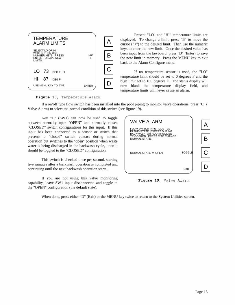
Present "LO" and "HI" temperature limits are displayed. To change a limit, press "B" to move the cursor ("<") to the desired limit. Then use the numeric keys to enter the new limit. Once the desired value has been input from the keyboard, press "D" (Enter) to save the new limit in memory. Press the MENU key to exit back to the Alarm Configure menu. If no temperature sensor is used, the "LO" temperature limit should be set to 0 degrees F and the high limit set to 100 degrees F. The status display will now blank the temperature display field, and temperature limits will never cause an alarm.
If a on/off type flow switch has been installed into the pool piping to monitor valve operations, press "C" ( Valve Alarm) to select the normal condition of this switch (see figure 19).
A
B
C
D
VALVE ALARM
EXIT
NORMAL STATE = OPEN
NORMAL STATE.TRIGGERED. PRESS C TO CHANGEBACKWASH) OR ALARM WILL BEIN THIS STATE (EXCEPT DURINGFLOW SWITCH INPUT MUST BE
TOGGLE
Figure 19, Valve Alarm
Key "C" (SW1) can now be used to toggle between normally open "OPEN" and normally closed "CLOSED" switch configurations for this input. If this input has been connected to a sensor or switch that presents a "closed" switch contact during normal operation but switches to the "open" position when waste water is being discharged in the backwash cycle, then it should be toggled to the "CLOSED" configuration. This switch is checked once per second, starting five minutes after a backwash operation is completed and continuing until the next backwash operation starts. If you are not using this valve monitoring capability, leave SW1 input disconnected and toggle to the "OPEN" configuration (the default state). When done, press either "D" (Exit) or the MENU key twice to return to the System Utilities screen.
Page 15

Manual Operations From the System Utilities menu, press "A" for Manual Operations (see figure 20).
A
B
C
D
MANUAL OPS
BACKWASH OR POWER-
EXIT
SAVE WILL OCCUR.
OR MANUAL OPERATION.SYSTEM BETWEEN AUTOMATICSELECT C TO TOGGLE
OR STOP PUMP OR HEATERSELECT B TO START
BACKWASH.AN UNSCHEDULEDSELECT A TO FORCE
WHEN IN MANUAL, NO AUTO
POOL OPERATION IS AUTOMATIC
MANUALAUTO/
PUMP/HEATER
FORCEBCKWSH
Figure 20, Manual Operations
From this menu, it is possible to force an immediate backwash (select "A"), start and stop the system pump and/or heater from the keyboard (select "B"), or enable/disable automatic backwash scheduling (select "C"). Key "C" acts directly to switch the controller between AUTOMATIC and MANUAL operations. If you wish to trigger all pool functions from the keyboard, press "C" to place the pool in MANUAL operating mode. Now all Backwash modes or Power Saver periods programmed will be ignored, and the pool will stay in its present state until a manual operation such as FORCE BCKWSH or PUMP/HEATER is requested.
If an alarm condition has caused the pool to switch to the MANUAL mode of operation (this status is displayed at the bottom of the main status screen), first determine the cause of the alarm and fix the problem, then reset the alarm from the ALARM CONFIGURATION screen (see above), and then enter this MANUAL OPS screen and press "C" to switch the controller back to AUTOMATIC operation. It will also be necessary to enter the PUMP/HEATER screen to turn the pump and heater back on to resume pool filtration operations.
A
B
C
D
PUMP AND HEATER
EXIT
PUMP IS ON
POWER TO HEATERPRESS C TO TOGGLE
POWER TO PUMPPRESS B TO TOGGLE
HEATER IS ONTOGLHEAT
PUMPTOGL
Figure 21, Pump and Heater
From the Manual Operations menu, press "B" (Pump/Heater) and the menu presented in figure 21 will be displayed. Key "B" can be pressed to cycle power to the pump. The system contains interlocks that prevent the pump from being turned off when the heater is on. See warning below. Key "C" can be pressed to cycle power to the heater. The system contains interlocks that prevent the heater from being turned on if the pump is not running. See warning below. The current status of the pump and heater are displayed for operator convenience. WARNING Cycling power to the heater while the pump is off is not allowed by the system. Also, after
cycling power to the heater, the firemans delay is activated to prevent turning off the pump before residual heat has dissipated from the heater. If the firemans delay is in effect, a message is presented at the bottom of the screen indicating how many seconds are remaining before the pump can be turned off.
Page 16

A backwash can be initiated from the keyboard at any time. From the Manual Operations menu, press "A" to select "Force Backwash".
A
B
C
D
FORCE BACKWASH
EXIT
CURRENT BACKWASH.USE C TO CANCEL
STAGE.ADVANCE TO NEXTBACKWASH OR TOUSE B TO START A
CANCEL
START/ADVANCE
Figure 22, Force Backwash
To begin a backwash cycle, press "B" (Start/Advance). A message at the bottom of the display indicates which filter is currently selected and which phase of the backwash operation the controller is presently executing. Refer to the "Backwash Operation Details" on page 5 for a description of the various phases of the backwash cycle. If you wish to advance to the next phase of the backwash cycle without waiting for the programmed time delays, the "Start/Advance" key can be pressed again to advance immediately to the next phase. When advancing manually through the "Interfilter Delay" phase, the operator must use caution to allow sufficient time for accumulated effluent to drain off before cycling to the next filter. Also, some phases of the backwash cycle are not immediately obvious and do not result in a change to the message at the bottom of the screen. For instance, during a backwash cycle, there is a 60 second delay between when the AUX3 relay comes on and when AUX2 comes on. This delay can be bypassed by pressing the START/ADVANCE key once, but will not result in a new message at the bottom of the screen. Once "B" has been pressed to start a backwash cycle, the system will proceed through a complete backwash of all of the filters in the system. Automatic backwashes that have been scheduled on a time interval basis will be rescheduled in light of the forced backwash. If you wish to terminate a forced backwash cycle before it has proceeded to completion, press "C" (Cancel) and the controller will return the Multiport Valve to the "Home" position and resume normal operation. Backwash cycles that have been "Canceled" will not increment the backwash counter. If automatically triggered backwashes are not desired because pool maintenance personnel are expected to perform this operation as needed, the automatic backwash scheduling functions of the controller can be disabled by placing the controller into the "MANUAL" mode of operation. From the Manual Operations menu, press "C". Notice that the status message at the bottom of the screen changes to indicate the current status of the controller. This same information will be presented at the bottom of the Status screen. If the system is in MANUAL, energy saver cycles will also not be executed on an automatic basis.
Page 17

Select Operating Mode The controller can be instructed to initiate backwash cycles based upon ten different combinations of filtration system conditions. The controller refers to these possible combinations as "Operating Modes". To select an operating mode, return to the main menu by pressing "M" and then press "A" (Select Op Mode). A series of ten screens will be presented, each describing one operating mode. Use the "A" and "B" keys to scroll through the choices until the desired one is reached. Time Interval Mode
A
B
C
D
SELECT
ENTER
DESIRED TIME INTERVALPRESS D TO ENTER
TIME.BASED SOLELY ON ELAPSEDBACKWASH WILL OCCUR
TIME INTERVAL
OP MODE
TIME INTERVALPRESENT MODE =
ESCAPE
NEXTCHOICE
PREV.CHOICE
Figure 23, Time Interval
In this mode, the controller keeps track of the elapsed time since last backwash. When this elapsed time equals the user entered interval, a backwash is executed, and the cycle repeats. If a backwash is initiated from the MANUAL OPS screen while in this mode of automatic backwash operation, the time interval is restarted and automatic operation resumes. If this time interval times out and requests a backwash while the pool is in an Energy Saver cycle, the backwash will occur as soon as the Energy Saver cycle is completed and the pool is turned back on. To select this mode, press "D" (Enter). You will be presented with a menu that prompts you to enter the desired time interval.
A
B
C
D
ELAPSED TIME
ENTER
OLD SETPOINT.WITHOUT CHANGINGUSE ESCAPE TO EXIT
TIME INTERVAL.ENTER NEW ELAPSEDUSE NUMBER KEYS TO
SAVE NEW SETPOINT.PRESS ENTER TO
ESCAPEMIN.60
Figure 24, Set Time Interval
Use the numeric keys to enter a time interval between 0 and 99999 minutes (about 2 months) and then press "D" to enter the new interval into system memory. If a mistake is made, press 0 five times to clear out the field, then try again. After pressing either "C" (to escape without changing the programmed interval) or "D" (to enter a new interval), you will be returned to the Select Op Mode menu. Notice that the status line at the bottom of the display now reads "Interval" to reflect the new operating mode. Although some operating modes provide a combination of more than one condition to initiate a backwash, only one operating mode may be active at any given time.
In this "Time Interval" operating mode, if a time interval was still counting down from a previous "time interval" backwash, the old interval will continue to count down and eventually cause a backwash. The new interval will then go into effect after this backwash. For this reason, you may want to manually initiate a backwash when changing the time interval value to cause the new interval to take effect immediately. The time interval does not decrement during an Energy Saver cycle as no water is being filtered at this time. Also, the time interval does not decrement during a power failure, although the time remaining is saved until power resumes and the countdown continues.
Page 18

Differential Pressure Mode
A
B
C
D
SELECT
ENTER
DESIRED PRESSURE.PRESS D TO ENTER
PRESSURE ACROSS THEBASED SOLELY ON BACK-BACKWASH WILL OCCUR
DIFFERENTIAL
OP MODE
TIME INTERVALPRESENT MODE =
ESCAPE
NEXTCHOICE
PREV.CHOICE
PRESSURE
FILTRATION SYSTEM.
Figure 25, Differential Pressure
In this mode, the controller looks at the inlet and outlet pressures present in the filtration system. When the difference between these two pressures exceeds a user selected limit (indicating that the filters are becoming clogged), a backwash cycle is executed, and pressure monitoring is resumed. The differential pressure must exceed the pressure set point for a continuous length of time greater than the "Surge Delay" programmed in the "Backwash Parameters" screens before a pressure differential backwash is initiated. This feature prevents temporary pressure excursions caused by extraneous events not related to filter back pressure from accidentally initiating a backwash. To select this mode, scroll through the modes until "Differential Pressure" is displayed. Press "D" (Enter). You will be presented with a menu that prompts you to enter the desired differential pressure set point.
A
B
C
D
SET PRESSURE
ENTER
SETPOINT.WITHOUT CHANGINGUSE ESCAPE TO EXIT
PRESSURE SETPOINT..ENTER NEW DIFFERENTIALUSE NUMBER KEYS TO
SAVE NEW SETPOINT.PRESS ENTER TO
ESCAPEPSI7
Figure 26, Differential Pressure Set
Use the numeric keys to enter a differential pressure between 0 and 99 psi (or 0.0 and 9.9 Barr if Engr. Units = Metric) and then press "D" to enter the new set point. After pressing either "C" (to escape without changing the programmed differential pressure set point) or "D" (to enter the new set point), you will be returned to the Select Op Mode menu. Notice that the status line at the bottom of the display should now indicate "Differential Pressure" to reflect the operating mode just selected.
Note: Because this mode looks only at differential pressure to determine if a backwash cycle
is required, it is possible that a backwash will not lower the differential pressure to below the set point. This results in continuously repeating backwash cycles. After three repeats, the alarm will energize (if enabled), the pump and heater will be turned off, and the controller will switch to the MANUAL mode of operation.
This condition may be induced by setting the differential pressure set point too low, or may be an indication that the filtration system is in need of maintenance.
Page 19
Flow Rate Mode
A
B
C
D
SELECT
ENTER
DESIRED FLOW RATE.PRESS D TO ENTER
OF FLOW THROUGH THEBASED SOLELY ON RATEBACKWASH WILL OCCUR
FLOW RATE
OP MODE
TIME INTERVALPRESENT MODE =
ESCAPE
NEXTCHOICE
PREV.CHOICE
FILTRATION SYSTEM.
Figure 27, Flow Rate
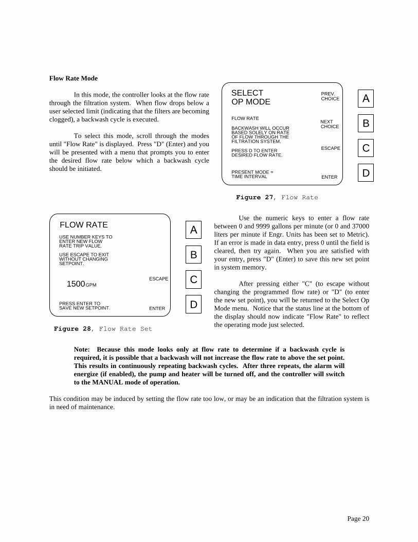
In this mode, the controller looks at the flow rate through the filtration system. When flow drops below a user selected limit (indicating that the filters are becoming clogged), a backwash cycle is executed. To select this mode, scroll through the modes until "Flow Rate" is displayed. Press "D" (Enter) and you will be presented with a menu that prompts you to enter the desired flow rate below which a backwash cycle should be initiated.
A
B
C
D
FLOW RATE
ENTER
SETPOINT.WITHOUT CHANGINGUSE ESCAPE TO EXIT
RATE TRIP VALUE.ENTER NEW FLOWUSE NUMBER KEYS TO
SAVE NEW SETPOINT.PRESS ENTER TO
ESCAPEGPM1500
Figure 28, Flow Rate Set
Use the numeric keys to enter a flow rate between 0 and 9999 gallons per minute (or 0 and 37000 liters per minute if Engr. Units has been set to Metric). If an error is made in data entry, press 0 until the field is cleared, then try again. When you are satisfied with your entry, press "D" (Enter) to save this new set point in system memory. After pressing either "C" (to escape without changing the programmed flow rate) or "D" (to enter the new set point), you will be returned to the Select Op Mode menu. Notice that the status line at the bottom of the display should now indicate "Flow Rate" to reflect the operating mode just selected.
Note: Because this mode looks only at flow rate to determine if a backwash cycle is
required, it is possible that a backwash will not increase the flow rate to above the set point. This results in continuously repeating backwash cycles. After three repeats, the alarm will energize (if enabled), the pump and heater will be turned off, and the controller will switch to the MANUAL mode of operation.
This condition may be induced by setting the flow rate too low, or may be an indication that the filtration system is in need of maintenance.
Page 20

Volume Mode
A
B
C
D
SELECT
ENTER
DESIRED VOLUME.PRESS D TO ENTER
OF WATER FILTEREDBASED SOLELY ON VOLUMEBACKWASH WILL OCCUR
VOLUME
OP MODE
TIME INTERVALPRESENT MODE =
ESCAPE
NEXTCHOICE
PREV.CHOICE
SINCE THE LAST BACKWASH.
Figure 29, Volume Mode
In this mode, the flow rate is used to calculate the total volume that has passed through the filtration system since the last backwash. When this volume exceeds a user selected limit, a backwash is executed. After the backwash is finished, the volume since last backwash is reset to zero and the cycle is repeated. To select this mode, scroll through the modes until "Volume" is displayed. Press "D" (Enter). You will be presented with a menu that prompts you to enter the desired volume to be filtered between backwashes.
A
B
C
D
VOLUME
ENTER
SETPOINT.WITHOUT CHANGINGUSE ESCAPE TO EXIT
VOLUME SETPOINT..TO ENTER NEWUSE NUMBER KEYS
SAVE NEW SETPOINT.PRESS ENTER TO
ESCAPEGAL*1000100
Figure 30, Set Volume
Use the numeric keys to enter a volume between 0 and 999,999 gal*1000 (or 0 and 370,000 liters*1000 if Metric has been selected for Engr. Units). Notice that numbers entered here are in thousands. To enter 47,000 gallons, enter 47. Press "D" to save the new volume set point into system memory. After pressing either "C" (to escape without changing the programmed volume) or "D" (to enter the new volume set point into memory), you will be returned to the Select Op Mode menu. Notice that the status line at the bottom of the display now reflects the "Volume" mode of operation.
Note: This mode looks only at volume filtered to determine if a backwash cycle is required,
it is possible that back pressure across the filters will become so large as to decrease flow rate and prevent sufficient volume from accumulating to trigger a backwash. Unlike incorrect pressure or flow set points which result in too frequent backwash operations, this situation results in no backwash operation and no alarm condition.
Page 21

Time of Day Mode
A
B
C
D
SELECT
ENTER
DESIRED TIME OF DAY.PRESS D TO PROGRAM
DAY ON ENABLED DAYS.THE SPECIFIED TIME OFBACKWASH WILL OCCUR AT
TIME OF DAY
OP MODE
TIME INTERVALPRESENT MODE =
ESCAPE
NEXTCHOICE
PREV.CHOICE
Figure 31, Time of Day Mode
In this mode, the system clock and calendar are used to determine when the next backwash should be initiated. This mode is useful when it is desirable to perform backwash operations at "off peak" times as dictated by waste water charges or pool usage patterns. With this mode, only one backwash can be scheduled per day. Because of this, the Time of Day operating mode is not appropriate where frequent backwash operations are required (more than once per day). If a backwash operation is inadvertently scheduled to occur during an Energy Saver cycle, the backwash will be initiated when the Energy Saver cycle ends, regardless of the time of day. To select this mode, scroll through the modes until "Time of Day" is displayed. Press "D" (Enter).
A
B
C
D
SET TIME OF DAY
ENTER
P
OR PM.KEYS, THEN SELECT AMSTART TIME USING NUMBERENTER DESIRED BACKWASH
SAVE NEW TIME.PRESS ENTER TO
CLEARM10:00
PMAM/
Figure 32, Set Time of Day
You will be presented with a menu that prompts you to enter the desired time of day in hours and minutes. Use the numeric keys to enter a time in hours and minutes. You must then select "am" or "pm" using "B" to toggle this field. If you make a mistake, press "C" to clear out the incorrect value and try again. If you wish to exit this screen without changing anything, press "MENU" to return to the "SELECT OP MODE" screen. When satisfied with your entry, press "D" to save the new time of day set point into system memory. You will be presented with a new screen to select which days you want to backwash (see figure 33).
Use the "SELECT" key to pick a day, then use "TOGGLE" to enable (YES), or disable (NO) backwash activity on the selected day. A
B
C
D
SELECT DAYS
ENTER
MONDAY = YES
THEN B TO TOGGLE YES OR NO.BY PRESSING A TO SELECT,ENABLE OR DISABLE DAYS
TO BACKWASH
THURSDAY = YESWEDNESDAY = YES ESCAPE
SUNDAY = NO
TUESDAY = YES
TOGGLE
SELECT
FRIDAY = YESSATURDAY = NO
<
Figure 33, Set Days to Backwash
Press "D" to save this new information (or press "C" to escape without change. You will be returned to the "SELECT OP MODE" screen. Notice that the status line at the bottom of the display now reflects the "Time of Day" mode of operation.
Page 22

Time or Pressure Mode Some combinations of the above parameters are also available. These combination modes are useful when it is desirable to do a backwash every so often as a scheduled event, but also as a result of filter conditions if pool usage has been unusually heavy. These modes also can be used to circumvent many of the difficulties outlined in the note sections above.
A
B
C
D
SELECT
ENTER
TIME AND PRESSURE.PRESS D TO PROGRAM
EXCEEDS LIMIT OR WHENWHEN THE BACKPRESSUREBACKWASH WILL OCCUR
TIME OR PRESSURE
OP MODE
TIME INTERVALPRESENT MODE =
ESCAPE
NEXTCHOICE
PREV.CHOICE
TIME INTERVAL IS UP,WHICHEVER OCCURS FIRST.
Figure 34, Time or Pressure
In the Time or Pressure mode, a backwash cycle is executed when either the user selected time interval is exceeded or differential pressure across the filters exceeds the user selected pressure limit, which ever happens first. Regardless of which parameter caused the backwash, elapsed time since last backwash is reset to zero and the cycle repeats. To select this mode, scroll through the operating modes with the PREV and NEXT keys until "TIME OR PRESSURE" is displayed, then press the "D" (enter) key. Screens will be presented for entering a time interval (see Elapsed Time above) and a differential pressure (see Set Pressure above). Note: As with the Differential Pressure Mode, it is possible to arrive at a condition where
backwash cycles are occurring continuously. If this happens, verify that the differential pressure set point has not been set too low. If not, the filtration system may be in need of maintenance.
Time and Pressure Mode
A
B
C
D
SELECT
ENTER
TIME AND PRESSURE.PRESS D TO PROGRAM
LIMIT IS EXCEEDEDONLY IF THE BACKPRESSUREBACKWASH WILL OCCUR
TIME AND PRESSURE
OP MODE
TIME INTERVALPRESENT MODE =
ESCAPE
NEXTCHOICE
PREV.CHOICE
WHEN ELAPSED TIME EXPIRES.
Figure 35, Time and Pressure
In this mode, the controller triggers backwash cycles based on differential pressure, but will backwash no more frequently than the user selected time interval. This mode is useful for insuring that high differential pressure across the filters will initiate a backwash while preventing backwash operations from occurring too frequently. To select this mode, scroll through the operating modes with the PREV and NEXT keys until "TIME AND PRESSURE" is displayed, then press the "D" (enter) key. Screens will be presented for entering a time interval (see Elapsed Time above) and a differential pressure (see Set Pressure above).
Page 23
Volume or Pressure Mode
A
B
C
D
SELECT
ENTER
PRESS D TO ENTER
WHICHEVER OCCURS FIRST.OR ELAPSED TIME EXPIRES,EXCEEDS THE SETPOINTWHEN THE VOLUME FILTEREDBACKWASH WILL OCCUR
VOLUME OR PRESSURE
OP MODE
VOLUME AND PRESSURE
TIME OF DAYPRESENT MODE =
ESCAPE
NEXTCHOICE
PREV.CHOICE
Figure 36, Volume or Pressure
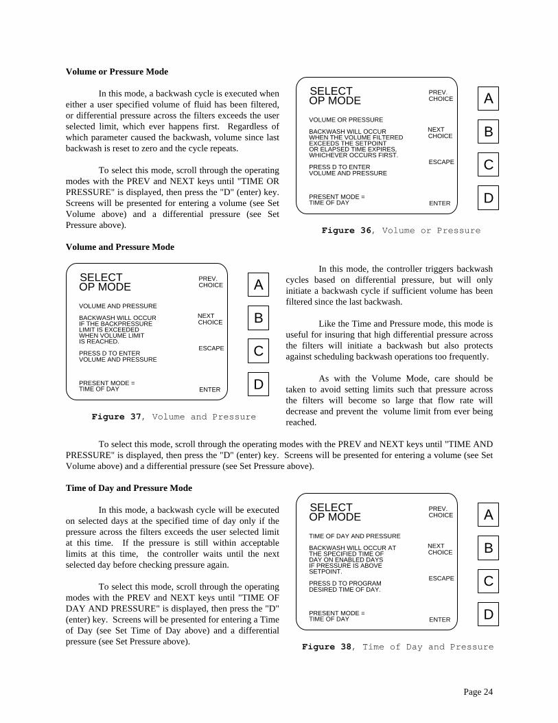
In this mode, a backwash cycle is executed when either a user specified volume of fluid has been filtered, or differential pressure across the filters exceeds the user selected limit, which ever happens first. Regardless of which parameter caused the backwash, volume since last backwash is reset to zero and the cycle repeats. To select this mode, scroll through the operating modes with the PREV and NEXT keys until "TIME OR PRESSURE" is displayed, then press the "D" (enter) key. Screens will be presented for entering a volume (see Set Volume above) and a differential pressure (see Set Pressure above). Volume and Pressure Mode
A
B
C
D
SELECT
ENTER
PRESS D TO ENTER
IS REACHED.WHEN VOLUME LIMITLIMIT IS EXCEEDEDIF THE BACKPRESSUREBACKWASH WILL OCCUR
VOLUME AND PRESSURE
OP MODE
VOLUME AND PRESSURE
TIME OF DAYPRESENT MODE =
ESCAPE
NEXTCHOICE
PREV.CHOICE
Figure 37, Volume and Pressure
In this mode, the controller triggers backwash cycles based on differential pressure, but will only initiate a backwash cycle if sufficient volume has been filtered since the last backwash. Like the Time and Pressure mode, this mode is useful for insuring that high differential pressure across the filters will initiate a backwash but also protects against scheduling backwash operations too frequently. As with the Volume Mode, care should be taken to avoid setting limits such that pressure across the filters will become so large that flow rate will decrease and prevent the volume limit from ever being reached.
To select this mode, scroll through the operating modes with the PREV and NEXT keys until "TIME AND PRESSURE" is displayed, then press the "D" (enter) key. Screens will be presented for entering a volume (see Set Volume above) and a differential pressure (see Set Pressure above). Time of Day and Pressure Mode
A
B
C
D
SELECT
ENTER
PRESS D TO PROGRAM
SETPOINT.IF PRESSURE IS ABOVEDAY ON ENABLED DAYSTHE SPECIFIED TIME OFBACKWASH WILL OCCUR AT
TIME OF DAY AND PRESSURE
OP MODE
DESIRED TIME OF DAY.
TIME OF DAYPRESENT MODE =
ESCAPE
NEXTCHOICE
PREV.CHOICE
Figure 38, Time of Day and Pressure
In this mode, a backwash cycle will be executed on selected days at the specified time of day only if the pressure across the filters exceeds the user selected limit at this time. If the pressure is still within acceptable limits at this time, the controller waits until the next selected day before checking pressure again. To select this mode, scroll through the operating modes with the PREV and NEXT keys until "TIME OF DAY AND PRESSURE" is displayed, then press the "D" (enter) key. Screens will be presented for entering a Time of Day (see Set Time of Day above) and a differential pressure (see Set Pressure above).
Page 24

Installation and Field Service To gain access to fuses and solid state relays, refer to figure 33 on the next page and remove the two screws marked "A". The power switch should then be unplugged from the circuit board to completely remove this access cover. Relay and fuse information can be found on a decal inside the front door. Field wiring diagrams can be found in the appendix of this manual. To gain access to the display contrast adjustment or to replace batteries, remove the four screws marked "B" and then remove the plastic front panel. The display can be adjusted for viewing angle and contrast with a potentiometer marked "C" in figure 1. To make this adjustment, reconnect the power switch and apply power to illuminate the display (no dangerous voltages are present, but care should be taken not to short out any of the circuitry as damage to the controller may result). With a small screwdriver, adjust potentiometer "C" for optimum viewing. All system parameters are stored in Electrically Alterable Read Only Memory (EEPROMs) and do not rely on batteries. The controller uses two size "AAA" NICAD batteries to supply power to the clock. The system contains a recharge circuit that keeps these batteries charged when the unit is operating. The batteries are capable of backing up the system clock for a couple of months on a single charge. The batteries recharge in about 24 hours once the power is again applied to the controller. These batteries should last for many years in this application. Should they need replacing (as evidenced by the clock losing track of time when the unit is temporarily powered down),, cut the plastic tie holding the batteries (this tie is for shipping only and need not be replaced) and replace the batteries. Reinstall covers and power up the controller. Reprogram time and date.
Page 25

AA
B
B
B
B
C
D
Figure 39, User Service
Page 26

Appendix A

Although the ‘Operator’s Manual’ has been written assuming a “standard” swimming pool filtration system configuration that includes a pump, a heater, and a multiport valve for shifting filters in and out of backwash, the Stark Controller has additional capabilities to accommodate other configurations. This appendix describes changes in controller operation from that described in the main text of the ‘Operator’s Manual’ that will be observed if the controller has been setup by the installer (as described in the ‘Installer’s Manual’) for one of these alternate configurations: No Multiport Valve On filtration systems with four or fewer filters, filters may be shifted in and out of backwash through the use of individual solenoid actuated valves instead of a multiport valve. On systems configured for solenoid operation, the backwash cycle proceeds as follows: - First, the controller energizes the “Master” relay, but instead of this “Master” being the Auxiliary Output 1,
as in the standard configuration, it has moved to the “Valve” output. You must consult your field wiring diagram to find out where to access this output for use in controlling other devices such as ozone and chemical controllers that you may wish to suspend while a backwash is in process.
- Next, the controller turns on Auxiliary Output 1. This output is now intended to energize the solenoid(s)
necessary to place filter 1 into the backwash configuration. After energizing this output, the controller waits 60 seconds for the hydraulic valves to switch to their new positions.
- The controller then waits for a user specified period of time for the filter to backwash ("Backwash
Duration"). - Auxiliary Output1 is then turned off (waiting 60 seconds for the hydraulic valves to finish shifting back
into their normal filter position) and the controller waits for a user selected time interval ("Interfilter Delay") before starting backwash of the next filter.
This cycle is repeated for each filter in the system with Auxiliary Output 2 being energized in turn to control solenoids to place filter 2 into backwash, Auxiliary Output 3 being energized for filter 3 backwash, and Auxiliary Output 4 being energized for filter 4 backwash. After all filters have been backwashed, and the Auxiliary Output associated with that filter has been de-energized, the controller waits for a valve shift delay of 60 seconds and then turns off the “Master” relay. The controller then waits until conditions once again call for a backwash. Notice that there is no “Aux 4” cycle if the system is configured for solenoid operation. In fact, the screen under “Backwash Parameters” (Page 2) where this Aux 4 cycle is normally configured now only contains the “Firemans Delay” parameter. If your system uses solenoids for shifting valves, this absence of Aux 4 references in the “Backwash Parameters” screens is a good way to verify that the controller is configured correctly for your system. No Heater If no heater is present in your system, or there is not a need to control the heater with the Stark controller, this output may have been configured by the installers as Auxiliary Output 5. This output is useful to manage units such as heaters and ozone systems that rely on the pump for their source of water. This output differs from the standard “Heater” output in that this output is energized “Aux 5 Delay” before turning the pump off for any reason as is the heater, but is also turned on an “Aux 5 Delay” before starting a backwash cycle even if the pump is not going to be turned off to shift the valves. The Auxiliary Output 5 is turned off at the end of a backwash cycle after the valves have all moved back to their normal “filter” position. Auxiliary Output 5 is available on both multiport valve and solenoid valve systems.
Page 2

Second Flow Meter Provisions have been provided on the Stark controller for a second paddlewheel flow sensor. A possible use for this second sensor would be to monitor the volume of waste water that is discharged into the local sewer system. If a second flow sensor is installed, a “K” factor should be entered for this sensor in the “Flow Calibration” screen. If a value other than 0.000 is entered here, the main status screen will show this new sensor flow rate and accumulated volume in place of the normal accumulated volume display. The normal (flow sensor 1) flow rate display is replaced by a combined flow rate and accumulated volume for the first sensor. The volume accumulated from flow sensor 1 is reset to zero at the start of each backwash cycle automatically. The volume accumulated from flow sensor 2 continues to increase until reset by the user. If a value other than 0.000 is entered for the “K” factor of sensor 2, the “Reset Backwash Counter” screen (see page 10) will be modified to allow key “B” to be used to reset the volume 2 total to zero when desired. Non Standard Relays The standard configuration described in the main text of the “Operator’s Manual” assumes that the Stark controller has been wired up in a “Failsafe” way. This means that if the controller fails for any reason or is removed for service, the pool will continue to operate normally, although without automatic backwash capability. This requires that the controller “energize” its pump and heater outputs to “turn off” the pool pump and heater. It is assumed that a normally closed relay is installed between the controller and the actual pump or heater switches, and that this NC relay will keep the pump and heater running in the absence of a signal from the controller. All other outputs (Aux 1 through 4 and Alarm Outputs) are assumed to be buffered from the actual connected devices by normally open relays. The installer may have chosen to wire some connected devices in some other configuration that requires that a particular output normally provided by the Stark controller be inverted. The controller supports these alternate configurations on an output by output basis. If any of these outputs have been re-configured by the installer, they will act opposite of what is documented in this “Operator’s Manual” (i.e. they will be on when the manual says that they should be off, and off when the manual indicates that they should be on).
Page 3

Appendix B

Appendix C

System Hardware Specifications
Electrical Specifications Input Power: 20 to 28 VAC, 250 W Max. Three Switch Inputs: Dry contact switch closures (internally sourced with 100K resistors to 5 VDC) Multiport Valve Cam Position Switch Multiport Valve "Home" Position Switch Auxiliary Switch 1 Three Analog Inputs: 12 bit resolution Pool Temperature Sensor Filter Inlet Pressure Sensor Filter Outlet Pressure Sensor Two Pulse Inputs 10 mV to 5 V Peak to Peak signal 1 to 1000 Hz For paddle wheel type Flow Sensor Eight AC Outputs: Solid State Single Pole, Single Throw 24 VAC output at 2A max. each, 10A total Field Replaceable Fuse and Module Multiport Sequencing Motor Pump Relay Alarm Relay Heater Relay Auxiliary Output 1 Auxiliary Output 2 Auxiliary Output 3 Auxiliary Output 4 Environmental Specifications Temperature: 0 to 50 Degrees C (32 to 122 Degrees F) Operating. Humidity: 0% to 90% Relative Humidity (non-condensing) Enclosure Sealing: NEMA 4 (Hose Down) with access with door closed.
Page 2