Embed Size (px)
Citation preview
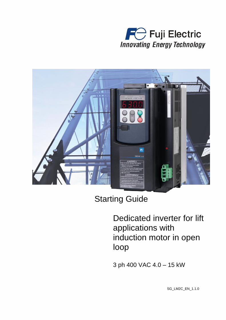
Starting Guide Dedicated inverter for lift applications with induction motor in open loop 3 ph 400 VAC 4.0 – 15 kW
SG_LM2C_EN_1.1.0

Page 2 of 28 Fuji Electric Europe GmbH
Version Changes applied Date Written Checked Approved 1.0.0 First release 25.10.2019 J. Alonso
1.0.1 Small text corrections 25.11.2019 J. Alonso C. Arjona J. Català
1.0.2 Chapter 7.1.4 correction Table and figure numbers correction
06.07.2020 C. Arjona J. Alonso J. Català
1.1.0
230V mode added Year of standards revised; RoHS 2 standard added Lift directive and notes on table 3.1 updated Section 5.1 title correction Table and figure numbers correction on chapter 5 Correction of parameter F21 on Figure 10.1 DBA alarm code added in chapter 13 Small text corrections
28.01.2021 C. Arjona J. Alonso J. Català
Page 3 of 28 Fuji Electric Europe GmbH
CONTENTS 0. About this manual ................................................................................................................................ 4 1. Safety information ................................................................................................................................ 4 2. Conformity to European standards ...................................................................................................... 6 3. Technical data ..................................................................................................................................... 7
3.1 Specifications.................................................................................................................................. 7 3.2 Three-phase 230V mode specifications ......................................................................................... 8 3.3 External dimensions ....................................................................................................................... 9
4. Removal and attachment of front cover............................................................................................... 9 5. Connections .......................................................................................................................................10
5.1 Power terminals connection .........................................................................................................10 5.2 Control signals connection ...........................................................................................................11 5.3 Use of input terminals for speed set point selection .....................................................................11 5.4 Control terminals description ........................................................................................................11
6. Hardware configuration .....................................................................................................................14 7. Keypad operation ...............................................................................................................................15
7.1 TP-E1U (Basic keypad) ................................................................................................................15 7.1.1 Led monitor, keys and LED indicators on the keypad ...........................................................15 7.1.2 Overview of operation modes ................................................................................................16 7.1.3 USB connectivity ...................................................................................................................16 7.1.4 TP-E1U Menu ........................................................................................................................16
7.2 TP-A1-LM2 (Advanced keypad) ...................................................................................................18 7.2.1 Keypad keys ..........................................................................................................................18 7.2.2 Keypad menus .......................................................................................................................19 7.2.3 Example of function setting ...................................................................................................20 7.2.4 Display language setting .......................................................................................................20
8. Driving the motor ...............................................................................................................................21 8.1 Inverter initialization ......................................................................................................................21 8.2 Specific setting .............................................................................................................................21 8.3 Auto tuning procedure ..................................................................................................................21
9. Setting the speed profile ....................................................................................................................22 10. Signal time diagram for open loop (IM) .............................................................................................23 11. Travel optimization .............................................................................................................................24 12. Lift fine tuning (troubleshooting) ........................................................................................................25 13. Alarm messages ................................................................................................................................26

Page 4 of 28 Fuji Electric Europe GmbH
0. About this manual Thank you very much for choosing FRENIC-Lift (LM2) inverter series. FRENIC-Lift (LM2) inverter series are specially designed for operation of induction motors used in lift applications. Induction motors without encoder (open loop) can be controlled obtaining good performance and high positioning accuracy at stop. This starting guide includes the basic information and explanations about the connection and commissioning of FRENIC-Lift LM2C.
This starting guide is based on firmware version 1500 or later. For other software versions, please contact with Fuji Electric technical department.
Firmware version (ROM) can be monitored on TP-E1U in 5_14 (with E52=2) and on TP-A1-LM2 in PRG
> 3 > 4
For extended information about the product and its use, refer to below mentioned documents:
- FRENIC-Lift Reference Manual INR-SI47-1909_-E (RM). - FRENIC-Lift Instruction Manual INR-SI47-2224_-E (IM).
1. Safety information
Read this manual thoroughly before proceeding with installation, connections (wiring), operation, or maintenance and inspection. Ensure you have enough knowledge of the device and familiarize yourself with all safety information and precautions before proceeding to operate the inverter. Safety precautions are classified into the following two categories in this manual.
Failure to heed the information indicated by this symbol may lead to dangerous conditions,
possibly resulting in death or serious bodily injuries.
Failure to heed the information indicated by this symbol may lead to dangerous conditions,
possibly resulting in minor or light bodily injuries and/or substantial property damage.
Failure to heed the information contained under the CAUTION title can also result in serious consequences. These safety precautions are importance and must be observed at all times.
Application
• FRENIC-Lift is designed to drive a three-phase motor. Do not use it for single-phase motors or for other purposes.
Fire or an accident could occur.
• FRENIC-Lift may not be used for a life-support system or other purposes directly related to the human safety.
• Though FRENIC-Lift is manufactured under strict quality control, install safety devices for applications where serious accidents or material losses are foreseen in relation to the failure of it.
An accident could occur.
Installation
• Install the inverter on a non-flammable material such as metal.
Otherwise fire could occur.
• Do not place flammable object nearby.
Doing so could cause fire.
• Do not carry the inverter by its terminal block cover during transportation.
Doing so could cause a drop of the inverter and injuries.
• Prevent lint, paper fibres, sawdust, dust, metallic chips, or other foreign materials from getting into the inverter or from accumulating on the heat sink.
Otherwise, a fire or an accident might result.
• Do not install or operate an inverter that is damaged or lacking parts.
Doing so could cause fire, an accident or injuries.
• Do not stand on a shipping box.
• Do not stack shipping boxes higher than the indicated information printed on those boxes.
Doing so could cause injuries.
Page 5 of 28 Fuji Electric Europe GmbH
Wiring
• When wiring the inverter to the power supply, insert an appropriate mains disconnecting device (e.g. switch, contactor, breaker etc.) Use the devices within the recommended current range.
• Use wires size recommended in Instruction Manual.
• When wiring the inverter to the power supply that is 500 kVA or more, be sure to connect an optional DC reactor (DCR).
Otherwise, fire could occur.
• Do not connect a surge killer to the inverter's output (secondary) circuit.
Doing so could cause fire.
• Ground the inverter in compliance with the national or local electric standards.
Otherwise, electric shock could occur.
• Qualified electricians should carry out wiring.
• Disconnect power before wiring.
Otherwise, electric shock could occur.
• Install inverter before wiring.
Otherwise, electric shock or injuries could occur.
• Ensure that the number of input phases and the rated voltage of the product match the number of phases and the voltage of the AC power supply to which the product is to be connected.
Otherwise fire or an accident could occur.
• Do not connect the power supply wires to output terminals (U, V, and W).
• Connect the braking resistor only to the terminals DB and P(+).
Otherwise, fire could occur.
• Generally, control signal wires are not reinforced insulation. If they accidentally touch any of live parts in the main circuit, their insulation coat may break for any reasons. In such a case, ensure the signal control wire is protected from making contact with any high voltage cables.
Doing so could cause an accident or electric shock.
• Connect the three-phase motor to terminals U, V, and W of the inverter.
Otherwise injuries could occur.
• The inverter, motor and wiring generate electric noise. Ensure preventative measures are taken to protect sensors and sensitive devices from RF noise.
Otherwise an accident could occur.
Operation
• Be sure to install the terminal cover before turning the power ON. Do not remove the covers while power is applied.
Otherwise electric shock could occur.
• Do not operate switches with wet hands.
Doing so could cause electric shock.
• If the auto-reset function has been selected, the inverter may automatically restart and drive the motor depending on the cause of tripping.
(Design the machinery or equipment so that human safety is ensured after restarting.)
• If an alarm reset is made with the Run command signal turned ON, the inverter may start immediately. Ensure that the Run command signal is turned OFF in advance.
Otherwise an accident could occur.
• Ensure you have read and understood the manual before programming the inverter, incorrect parameter settings may cause damage to the motor or machinery.
An accident or injuries could occur.
• Do not touch the inverter terminals while the power is applied to the inverter even if the inverter is in stop mode.
Doing so could cause electric shock.

Page 6 of 28 Fuji Electric Europe GmbH
• Do not turn the main circuit power (circuit breaker) ON or OFF in order to start or stop inverter operation.
Doing so could cause failure.
• Do not touch the heat sink and braking resistor because they become very hot.
Doing so could cause burns.
• Before setting the speeds (frequency) of the inverter, check the specifications of the machinery.
• The brake function of the inverter does not provide mechanical holding means.
Injuries could occur.
Maintenance and inspection, and parts replacement
• Turn the power OFF and wait for at least five minutes before starting inspection. Further, check that the LED monitor is unlit and that the DC link bus voltage between the P (+) and N (-) terminals is lower than 25 VDC.
Otherwise, electric shock could occur.
• Maintenance, inspection, and parts replacement should be made only by qualified persons.
• Take off the watch, rings and other metallic objects before starting work.
• Use insulated tools.
Otherwise, electric shock or injuries could occur.
Disposal
• Treat the inverter as an industrial waste when disposing of it.
Otherwise injuries could occur.
Others
• Never attempt to modify the inverter.
Doing so could cause electric shock or injuries.
2. Conformity to European standards
The CE marking on Fuji Electric products indicates that they comply with the essential requirements of the Electromagnetic Compatibility (EMC) Directive 2014/30/EU and the Low Voltage Directive 2014/35/EU issued by the Council of the European Communities.
Inverters with built-in EMC filter that bear a CE marking are in conformity with EMC directives. Inverters having no built-in EMC filter can be in conformity with EMC directives if an optional EMC compliant filter is connected to them. General purpose inverters are subject to the regulations set forth by the Low Voltage Directive in the EU. Fuji Electric declares the inverters bearing a CE marking are compliant with the Low Voltage Directive.
FRENIC-Lift (LM2) inverter series are in accordance with the regulations of following council directives and their amendments:
- Electromagnetic Compatibility Directive: 2014/30/EU - Low Voltage Directive: 2014/35/EU - Machine Directive: 2006/42/EC - RoHS 2 Directive: 2011/65/EU For assessment of conformity, the following relevant standards have been taken into consideration:
- EMC: EN61800-3:2018, EN12015:2014, EN12016:2013. - Electrical Safety: EN61800-5-1:2007/A1:2017. - Functional Safety: EN61800-5-2:2017 SIL3, EN ISO13849-1:2015 PLe, Cat.3 Safe Torque Off. Pollution degree 3. - RoHS 2: EN50581:2012, EN IEC63000:2018.
The FRENIC-Lift (LM2) inverter series are categorized as category C2 or C3 according to EN61800-3:2018. When you use these products in the domestic environment, you may need to take appropriate countermeasures to reduce or eliminate any noise emitted from these products.

Page 7 of 28 Fuji Electric Europe GmbH
3. Technical data
3.1 Specifications
Table 3.1. FRENIC-Lift LM2C General specifications.
Item Specifications
Type FRN___LM2C-4E 0010 0015 0019 0025 0032
Nominal applied motor [kW] 4.0 5.5 7.5 11 15
Ou
tpu
t ra
tin
gs
Rated capacity*1 [kVA] 7.6 11 14 18 24
Rated voltage*2 [V] 3-phase 480 to 480 VAC
Rated current*3 [A] 10.0 15.0 18.5 21.4
(24.5) *8 32.0
Overload capacity [A] (Permissible overload time)
18.0 (3)
27.0 (3)
33.3 (3)
44.1 (3)
57.6 (3)
Inp
ut
rati
ng
s
Main
pow
er
su
pply
Norm
al
Phases, voltage, frequency 3-ph 380 to 480 VAC, 50/60 Hz
Variations: Voltage: +10 to -15% (Voltage unbalance: 2% or less*4), Frequency: +5 to -5%
Rated current*5 [A]
With DCR 7.5 10.6 14.4 21.1 28.8
Without DCR 13.0 17.3 23.2 33.0 43.8
Required power supply capacity (with DCR) [kVA]
5.2 7.4 10.0 15.0 20.0
UP
S Input power for driving
phases, voltage, frequency
1-ph 220 to 480 VAC, 50/60 Hz
Variations: Voltage: +10 to -10%, Frequency: +5 to -5%
Operation time [s] 180
Batte
ry
Input power for driving voltage
48 VDC
Operation time [s] 180
Aux. control power voltage 24 VDC (22 to 32 VDC), max. 40 W
Bra
kin
g Braking time*7 [s] 60
Braking duty-cycle (%ED)*7 [%] 50
Rated regenerative power*7 [kW] 3.2 4.4 6.0 8.8 12.0
Minimum resistance*6 [Ω] 96 47 47 24 24
Conformity standard
Lift Directive
- Replacement of two motor contactors: interrupting the current to the motor (to stop the machine), as required by EN 81-20:2014 5.9.2.5.4 d & 5.9.3.4.2 d - Brake monitoring for EN81-20:2014 5.6.7.3 Machinery Directive - EN ISO13849-1: PL-e - EN60204-1: stop category 0 - EN61800-5-2: STO SIL3 - EN62061: SIL3 Low Voltage Directive - EN61800-5-1: Over voltage category 3 EMC Directive - with external EMC filter EN12015, EN12016, EN 61800-3 +A1, EN 61326-3-1 (Emission): Category 2 (0025 (11kW) or lower) / Category 3 (0032 (15kW) or higher) (Immunity): 2nd Env. Canadian and U.S. standards - Can/CSA C22.2 No.14-13: Industrial Control Equipment - CSA C22.2 No.274-13: Adjustable speed drives - UL 508 C (3rd Edition): Power Conversion Equipment - According to CSA B44.1-11/ASME A17.5-2014: Elevator and escalator electrical equipment
Enclosure (IEC60529)
Main body IP20
Heat sink IP54
Cooling method Fan cooling
*1) Rated capacity is calculated by regarding the output rated voltage as 440 VAC. *2) Output voltage cannot exceed the power supply voltage. *3) These values correspond to the following conditions: carrier frequency is 8 kHz (2 phase modulation) and ambient temperature is 45°C. Select the inverter capacity such that the square average current during operation is not higher than the 80% of the rated current of the inverter. *4) Voltage unbalance [%] = (Max.voltage [V] - Min.voltage [V])/ Three-phase average voltage [V] x 6 (IEC61800-3). *5) The power supply capacity is 500kVA (ten times the inverter capacity when the inverter capacity exceeds 50kVA), and the value of the power supply impedance is %X=5%. *6) The admissible error of minimum resistance is ±5%. *7) Braking time and duty cycle (%ED) are defined by cycle operation at the rated regenerative power. *8) Rated current is for 45ºC, rated current in brackets corresponds to ambient temperature of 40ºC.

Page 8 of 28 Fuji Electric Europe GmbH
3.2 Three-phase 230V mode specifications
Table 3.2. 3ph 230V mode specifications *9
Item Specifications
Type FRN___LM2A-4E 0015 0019 0025 0032
Nominal applied motor [kW] 3.0 4.0 5.5 7.5
Ou
tpu
t ra
tin
gs
Rated capacity*1 [kVA] 6.0 7.4 9.8 12.7
Rated voltage*2 [V] 3-phase 220 to 230 VAC
Rated current*3 [A] 15.0 18.5 21.4
(24.5) *8 32.0
Overload capacity [A] 27.0 33.3 44.1 57.6
(Permissible overload time) (3s) (3s) (3s) (3s)
Inp
ut
rati
ng
s
Main
pow
er
su
pply
Norm
al
Phases, voltage, frequency 3-ph 230 VAC, 50/60 Hz
Variations: Voltage: +10 to -10% (Voltage unbalance: 2% or less*4), Frequency: +5 to -5%
Rated With DCR 10.6 14.4 21.1 28.8
Current*5 [A] Without DCR 17.3 23.2 31.5 42.7
Required power supply capacity (with DCR) [kVA]
4.2 5.7 8.4 11.5
UP
S Input power for driving phases,
voltage, frequency
1-ph, 220 to 240 VAC, 50/60 Hz
Variations: Voltage: +10 to -10%, Frequency: +5 to -5%
Operation time [s] 180
Batte
ry
Input power for driving voltage DC 48V or more in the direct current voltage conversion.
Operation time [s] 180
Aux. control power voltage 24 VDC (22 to 32 VDC), max. 40 W*10
Bra
kin
g Braking time*7 [s] 60
Braking duty-cycle (%ED)*7 [%] 50
Rated regenerative power*7 [kW] 2.4 3.2 4.4 6.0
Minimum resistance*6 [Ω] 24 24 16 12
Conformity standard
Lift Directive
- Replacement of two motor contactors: interrupting the current to the motor (to stop the machine), as required by EN 81-20:2014 5.9.2.5.4 d & 5.9.3.4.2 d - Brake monitoring for EN81-20:2014 5.6.7.3
Machinery Directive
- EN ISO13849-1: PL-e
- EN60204-1: stop category 0
- EN61800-5-2: STO SIL3
- EN62061: SIL3
Low Voltage Directive
- EN61800-5-1: Over voltage category 3
EMC Directive
- with external EMC filter EN12015, EN12016, EN 61800-3 +A1, EN 61326-3-1
(Emission): Category 2 (0025 (11kW) or lower) / Category 3 (0032 (15kW) or higher)
(Immunity): 2nd Env.
Canadian and U.S. standards
- Can/CSA C22.2 No.14-13: Industrial Control Equipment
- CSA C22.2 No.274-13: Adjustable speed drives
- UL 508 C (3rd Edition): Power Conversion Equipment
- According to CSA B44.1-11/ASME A17.5-2014: Elevator and escalator electrical equipment
Enclosure Main body IP20
(IEC60529) Heat sink IP54
Cooling method Fan cooling
*1) Rated capacity is calculated by regarding the output rated voltage as 440 VAC. *2) Output voltage cannot exceed the power supply voltage. *3) These values correspond to the following conditions: carrier frequency is 8 kHz (2 phase modulation) and ambient temperature is 45°C. Select the inverter capacity such that the square average current during operation is not higher than the 80% of the rated current of the inverter. *4) Voltage unbalance [%] = (Max.voltage [V] - Min.voltage [V])/ Three-phase average voltage [V] x 6 (IEC61800-3). *5) The power supply capacity is 500kVA (ten times the inverter capacity when the inverter capacity exceeds 50kVA), and the value of the power supply impedance is %X = 5%. *6) The admissible error of minimum resistance is ±5%. *7) Braking time and duty cycle (%ED) are defined by cycle operation at the rated regenerative power. *8) Rated current is for 45ºC, rated current in brackets corresponds to ambient temperature of 40ºC. *9) To activate this mode set F81=1. Available in FRN0015LM2C-4E to FRN0032LM2C-4E with ROM version 1500 or later. For additional information refer to INR-SI47-2354-E. *10) Only for rescue operation. Do not use during normal operation.

Page 9 of 28 Fuji Electric Europe GmbH
3.3 External dimensions
Table 3.2. External dimensions and frame definition. Power Supply
voltage Type Frame
W (mm)
H (mm)
D (mm)
3-ph 400 VAC
FRN0010LM2C-4E
1 140,0 260,0 195,0 FRN0015LM2C-4E
FRN0019LM2C-4E
FRN0025LM2C-4E
FRN0032LM2C-4E 2 160,0 360,0 195,0
FRN0010LM2C-4E to FRN0025LM2C-4E FRN0032LM2C-4E
4. Removal and attachment of front cover
In order to remove properly front cover, please follow the procedure below figure. In the following description, it is assumed that the inverter has already been installed.
Figure 4.1: Removing front cover step by step (Frame 1 & 2)

Page 10 of 28 Fuji Electric Europe GmbH
5. Connections
5.1 Power terminals connection
FRENIC-Lift (LM2)
DCRE4-x.x-J
(DC reactor)
(THR)
(PLC)
U V W
MOTOR
EMC G
PEN
P2 N(-)DB P3 P(+) G
M
*1
*2 *3
*4
*6
*6
BRE-xxRxxxxW
(braking resistor)
L1/R L2/S L3/T
Input
EMC filter
Figure 5.1. Power terminals connection.
Note *1: Not used. Note *2: DC Reactor terminals:
- In case of NOT installing DC Reactor wire a jumper between terminals P2 and P3. Note *3: Use the metal plates placed on removable terminals to connect the shield by means of metal cable ties for
example.
Note *4: In case of not installing the two MC between motor and inverter, please follow the procedure explained in “AN-
Lift2-0001” document. All the power terminals, independently of frame, even do not appear on figure 5.1 are listed in table 5.1.
Table 5.1. Power terminals description.
Terminal label Description of the power terminals
L1/R, L2/S, L3/T 3-phase supply input from mains supply.
U, V, W 3-phase motor connection for induction motors.
U0, V0, W0 Not used.
P2, P3 DC Reactor connection.
24V+, 24V- Input power terminals for 24 VDC. These terminals have to be used in case of rescue operation by means of batteries to supply control circuit.
DB , P(+) Connection of external braking resistor.
EMC Not used.
G Terminals for the connection of the inverter enclosure with the protecting earth.
3 terminals available.
Please connect the screen in both motor and inverter sides. Ensure that the screen is continued also through the
main contactors (if used).
It is recommended to use braking resistors with thermal switch in order to protect the system from failures. Additionally, inverter has a software function to electronically protect the system (For additional information please check parameters F50 to F52).

Page 11 of 28 Fuji Electric Europe GmbH
5.2 Control signals connection In figure 5.2 all control terminals included in the electronic boards are shown. Electronic boards are divided in control board (fixed) and I/O terminals board (removable). I/O terminals board can be easily removed from control board. EN circuit terminals have their own connector which can be removed as well. For additional information about wiring and terminals function refer to below sub chapters.
TERM5
TERM1
TERM1
TERM4
TERM3TERM2
CONTROL
BOARD
I/O TERMINALS
BOARD
Figure 5.2. Control board and I/O terminals board terminals
All the examples below are based on FRENIC-Lift (LM2C) default setting. For other functions please refer to FRENIC-Lift RM document.
5.3 Use of input terminals for speed set point selection
Table 5.2: Binary combination for speed selection
X3 (SS4)
X2 (SS2)
X1 (SS1)
Binary speed coding function
Value Selected Speed Speed set point function
0 0 0 L11 0 (000) Zero speed C04
0 0 1 L12 1 (001) Intermediate speed 1 C05
0 1 0 L13 2 (010) Inspection speed C06
0 1 1 L14 3 (011) Creep speed C07
1 0 0 L15 4 (100) Intermediate speed 2 C08
1 0 1 L16 5 (101) Intermediate speed 3 C09
1 1 0 L17 6 (110) Intermediate speed 4 C10
1 1 1 L18 7 (111) High speed 1 C11
In case that lift controller signals does not match with selected speed described in table 5.2, signals can be adapted by modifying the setting on parameters L11 to L18. In the example below (table 5.3), lift controller uses X2 and X1 as a High speed and X1 as a Creep speed.
Table 5.3: Example of binary combination for speed selection modification. SS4 (X3)
SS2 (X2)
SS1 (X1)
Binary speed coding function
Value Selected Speed Speed set point
function
0 0 0 L11 0 (000) Zero speed C04
1 1 1 L12 7 (111) Intermediate speed 1 C05
0 1 0 L13 2 (010) Inspection speed C06
0 0 1 L14 1 (001) Creep speed C07
1 0 0 L15 4 (100) Intermediate speed 2 C08
1 0 1 L16 5 (101) Intermediate speed 3 C09
1 1 0 L17 6 (110) Intermediate speed 4 C10
0 1 1 L18 3 (011) High speed 1 C11
5.4 Control terminals description
Control terminals can be classified between digital signals (input and output), analog signals (input and output) and communication ports. Below each type of terminal is described. All inputs and outputs can be freely programmed with any available function. For an easy set up all examples on this guide are referred to default configuration.
5.4.1 Analog inputs
Using analog inputs, the motor speed and the torque bias can be set without steps (stageless). Analog command signals can be either voltage or current on terminal [V2]; selection is done by means of slide switch SW4.

Page 12 of 28 Fuji Electric Europe GmbH
Terminal [NTC] can be used to connect a PTC/NTC thermistor for motor overheat protection. Function is disabled in factory setting, for additional information refer to description of parameter H26 in Reference Manual.
5.4.2 Digital inputs
Digital inputs can operate either in NPN or PNP logic. The selection of the logic is set on slide switch SW1 located on the control board. Factory setting is PNP (Source) Logic. Description of each input terminal function can be found on table 5.4.
Table 5.4: Description of digital inputs (optocoupled inputs).
On below figures, different input configuration examples are shown. On below images different connection examples using PNP Logic are shown:
FRENIC-Lift (LM2)
X1 FWD PLC (+24 V)Lift controller
Up direction
Speed 1
Figure 5.3: Connection using free potential contacts of lift controller.
FRENIC-Lift (LM2)
X1 FWD CM
Lift controller
Up direction
Speed 1
0 VDC
+24 VDC
24 VDC
Figure 5.4: Connection using external power supply.
As explained in table 5.4, even STO function is not used, a proper usage of EN terminals is recommended. In figure 5.5 an example of wiring is shown.
KM1
FRENIC-Lift (LM2)
PLCEN1
KM1.1KM2.1RM1.1
Safety chain/safety
controller
KM1 RM1
KM1.2
KM2.2
KM2
KM2
EN2
RM1.2
TERM1
M
Figure 5.5: Recommended wiring of EN circuit terminals.
Terminal Function description of the digital inputs
FWD Clockwise rotation of the motor seen from the shaft side. Depending on the mechanical set up this can be UP or DOWN direction of the car.
REV Anticlockwise rotation of the motor seen from the shaft side. Depending on the mechanical set up this can be DOWN or UP direction of the car.
CM Common 0 VDC.
X1 to X3 Digital inputs for speed selection. From binary combination, 7 different speeds can be selected.
X4 to X7 The default setting function of these terminals is not explained on this guide. For additional information refer to Reference Manual.
X8 Configured from factory as “BATRY” for Battery or UPS operation (Rescue operation).
EN1 & EN2
Inverters enable terminals (IGBT drives habilitation). These terminals complies with the STO SIL 3 function described in the standard 61800-5-2, therefore if properly used, these terminals can be used to substitute the two contactors between the inverter and the motor (as described on EN81-20:2014 5.9.2.5.4 d). For additional information regarding STO
function, refer to “AN-Lift2-0001” document. Even STO function is not used, the correct usage of these terminals is recommended. An incorrect usage of these terminals can deal to inverter trips (OCx trip) or even to the destruction of it. For additional information, refer to figure 5.5. The logic of these terminals is fixed to SOURCE. It does not depend on SW1 configuration.

Page 13 of 28 Fuji Electric Europe GmbH
Electrical specifications of digital inputs using PNP (Source) Logic is shown in table 5.5.
Table 5.5: Digital inputs electrical specifications.
Item Status Range
Voltage ON 22 to 27 V
OFF 0 to 2 V
Current ON Min. 2.5 mA /Max. 5.0 mA
5.4.3 Relay output
Terminals Y3 (A/C), Y4 (A/C), Y5 (A/C) and 30 (A/B/C) are configured from factory with the functions described in the table 5.6. Other functions can be set using functions from E22 to E30.
Table 5.6: Default setting and specifications of relay outputs.
Terminals Function description of the relay outputs
30A, 30B and 30C
Inverter in alarm status (ALM). In case of fault, the motor stops and the contact 30C-30A (NO) switches (closes). Contact rating: 250 VAC; 0.5 A / 30 VDC; 0.5A.
Y5A-Y5C Motor brake control function (BRKS). Contact rating: 250 VAC; 0.5 A / 30 VDC; 0.5A.
Y4A-Y4C Main MC control function (SW52-2). Contact rating: 250 VAC; 0.5 A / 30 VDC; 0.5A.
Y3A-Y3C Speed detected function (FDT). Contact rating: 250 VAC; 0.5 A / 30 VDC; 0.5A.
5.4.4 Transistor output
Terminals Y1 and Y2 are configured from factory with the functions described in the table 5.7. Other functions can be set using functions E20 and E21.
Lift controller
24 VDC
Relay or
Optocoupled inputs
FRENIC-Lift (LM2)
Y1 Y2 CMY
Optocoupled outputs
Figure 5.6: Connection using PNP (Source) Logic
Table 5.7: Default setting and specifications of transistor outputs.
Terminal Function description of the transistor outputs
Y1 Main MC control function (SW52-2).
Y2 Anticipated door opening control (DOPEN).
CMY Common for transistor outputs
Electrical specification of transistor outputs is shown in table 5.8.
Table 5.8: Output transistors electrical specifications.
Item Status Range (Max.)
Voltage ON 3 V
OFF 48 V
Operation current ON 50 mA
Leakage current OFF 0.1 mA
In case of Figure 5.6 example, the voltage OFF is 24 VDC (Power supply connected to CMY). Inductive loads should not be connected directly (they should be connected through a relay or optocoupler).
5.4.5 Communication ports
FRENIC-Lift (LM2) has up to three communication ports built-in. CAN bus is accessible by removable terminal TERM1 in I/O terminals board. RS-485 port 1 is accessible by RJ-45. RS-485 port 2 is accessible by I/O terminals board terminals DX+ and DX-.

Page 14 of 28 Fuji Electric Europe GmbH
Port 1 (Keypad, Modbus RTU, Loader software, DCP) Port 2 (Modbus RTU, Loader software, DCP) Port 3 (CAN bus)
For additional information about communication protocols refer to specific manual.
6. Hardware configuration Up to 5 slide switches can be found in the control and I/O terminals boards. With these switches different configurations can be set. Function of each switch and it possible configurations are shown in table 6.1.
Table 6.1: Configuration of the slide switches
Switch Slide switches factory setting
SW1 Digital inputs operation mode selection between PNP and NPN (SINK/SOUCE).
SW2 Terminating resistor of RS-485 communications port 1. Port 1 is in RJ-45 connector. (When keypad or converter for FRENIC Loader is used, set SW2 to OFF position). (When DCP or Modbus communication is used, set SW2 to ON position if needed).
SW3 Terminating resistor of RS-485 communications port 2. Port 2 is in I/O terminals board. (When converter for FRENIC Loader is used, set SW3 to OFF position). (When DCP or Modbus communication is used, set SW3 to ON position if needed).
SW4 [V2] terminal function selection between V2 (0 to ±10 VDC) and C1 (4 to 20 mADC).
SW5 Terminating resistor of CAN communications port. (When CANopen communication is used, set SW5 to ON position if needed).
By using the PTC input, the cut-off (stopping) function of the inverter does not fulfil EN81-20/50.
Figure 6.1 shows the position of the slide switches in the control and I/O terminals board. It shows as well the default position (factory default) of each switch.
SW1 SW2 SW3 SW4 SW5
Logic RS485 port 1
RS485 port 2
V2-C1 CAN
terminating resistor
Figure 6.1 Slide switches position and meaning

Page 15 of 28 Fuji Electric Europe GmbH
7. Keypad operation
7.1 TP-E1U (Basic keypad)
7.1.1 Led monitor, keys and LED indicators on the keypad
As shown on Figure 7.1, the keypad consists of a four-digit LED monitor, six keys, and five LED indicators. The keypad allows you to monitor the running status, specify the function code data, and monitor I/O signal states, maintenance information, and alarm information. The meaning of each part of the keypad is explained on Table 7.1.
Figure 7.1: Keypad overview
Table 7.1: Overview of Keypad Functions
Item LED Monitor,
Keys, and LED
Indicators Functions
LED
Monitor
Four-digit, 7-segment LED monitor which displays the followings according to the operation modes.
In Running mode: Running status information (Monitoring data according to E52 setting).
In Programming mode: Menu, function codes and their data.
In Alarm mode: Alarm code, which identifies the alarm factor when the protective function is activated.
Operation
Keys
Program/Reset key which switches the operation modes of the inverter.
In Running mode: Pressing this key switches the inverter to Programming mode.
In Programming mode: Pressing this key switches the inverter to Running mode.
In Alarm mode: Pressing this key after removing the alarm factor will switch the inverter to Running mode.
Function/Data key which switches the operations you want to do in each mode as follows:
In Running mode: Pressing this key switches the information to be displayed (Monitor data fixed on E52).
In Programming mode: Pressing this key displays the function code or establishes the data
entered with and keys.
In Alarm mode: Pressing this key displays the details of the problem indicated by the alarm code that has come up on the LED monitor.
Together with , keypad moves to Programming mode in case of Alarm status.
/ UP and DOWN keys. Press these keys to select the setting items and change the function code data displayed on the LED monitor.
LED
Indicators
RUN LED Lights when running with a run command entered by terminal command FWD or REV or through the communications link.
KEYPAD
CONTROL
LED Lights when the inverter is ready to run with a run command.
Unit LEDs
(3 LEDs)
These three LED indicators identify the unit of numeral displayed on the LED monitor in Running mode by combination of lit and unlit states of them. Unit: Hz, A, kW, r/min and m/min.
While the inverter is in Programming mode, the LEDs of Hz and kW light. Hz A kW
X10 LED
Lights when the data to display exceeds 9999. When this LED lights, the "displayed value x 10" is the actual value.
Example: If the LED monitor displays 1234 and the x10 LED lights, it means that the actual value is "1,234 10 = 12,340."
USB
port
The USB port with a Mini-B connector enables the inverter to connect with a PC with an USB cable.

Page 16 of 28 Fuji Electric Europe GmbH
7.1.2 Overview of operation modes
TP-E1U keypad can operate in the modes shown in Table 7.2.
Table 7.2. Keypad operation modes
Operation mode Description
Running mode The inverter cannot be operated by this keypad. Running mode is only to monitor Run status.
Programming mode This mode allows you to configure function code data and check a variety of information relating to the inverter status and maintenance.
Alarm mode If an alarm condition arises, the inverter automatically enters Alarm mode in which you can view the corresponding alarm code* and its related information on the LED monitor.
* Alarm code: Indicates the cause of the alarm condition. For details, please refer to Chapter 15.
Figure 7.2 shows the status transition of the inverter between these three operation modes.
Programming mode
Configuration of function code data and monitor of maintenance/alarm info and various status
Alarm mode
Display of alarm status
Occurrence of
a heavy alarm
(Press this key if
an alarm has
occurred.)
+
Running mode
Monitor of running status
Power ON
Release of
a heavy alarm
Figure 7.2. Status Transition between Operation Modes
Simultaneous keying
Simultaneous keying means pressing two keys at the same time. The simultaneous keying operation is expressed by a "+" letter between the keys throughout this manual.
For example, the expression " + keys" stands for pressing the key with the key held down.
7.1.3 USB connectivity
The keypad has an USB port (Mini-B connector) on its front. To connect an USB cable, open the USB port cover as shown below. The position of the USB port is shown in Figure 7.3.
Figure 7.3. Position of USB port.
For the instructions on how to use the FRENIC Loader 4, refer to the FRENIC Loader Instruction Manual.
7.1.4 TP-E1U Menu
Partial menu list can be accessed by pressing . In order to have all menus available please set E52=2.
0. Quick Setup (0.Fnc)
Display only basic function codes to customize the inverters operation. 1. Data Setting (From 1.F_ _ to 1.K_ _ )
Selecting each of these function codes enables its data to be displayed/changed. 2. Data Checking (2.rEP)
Display only function codes that have been changed from their factory defaults. You can refer to or change those function code data.

Page 17 of 28 Fuji Electric Europe GmbH
3. Drive Monitoring (3.oPE)
Displays the running information required for maintenance or test running.
Output frequency 3_00
Output current 3_02
Output torque 3_04
Motor speed 3_08
4. I/O Checking (4.I_o)
Display external interface information.
Segments LED 4 LED 3 LED 2 LED 1
a 30A/B/C Y1-CMY X7 FWD
b --- Y2-CMY --- REV
c --- Y3-CMY --- X1
d --- Y4-CMY EN1&2 X2
e --- Y5A-Y5C --- X3
f --- --- (XF)* X4
g --- --- (XR)* X5
dp --- --- (RST)* X6
If all terminal input signals are OFF (open), segment "g" on all of LED1 to LED4 will light ("– – – –"). (XF)*, (XR)*, (RST)* Only for communications. This information can be monitored in 4_00 menu.
5. Maintenance Information (5.CHE)
Display maintenance information including cumulative run time.
Cumulative RUN time 5_00
DC link bus voltage 5_01
Max. temperature inside the inverter 5_02
Number of startups 5_08
6. Alarm information (6.AL)
Display the recent four alarm codes. You can refer to the running information at the time when the alarm occurred.
Error sub code 6_21
7. Data Copying (7.CPY)
Allows you to read or write function code data, as well as verifying it. Customizable logic parameters are copied as well.
Example of Function setting
Example of function code data changing procedure is shown in Figure 7.4, in that case F01 is set from 0 to 2.
Figure 7.4. Function setting procedure
You can move the cursor when changing function code data by holding down the key for 1 second or longer.

Page 18 of 28 Fuji Electric Europe GmbH
7.2 TP-A1-LM2 (Advanced keypad)
7.2.1 Keypad keys
Keypad “TP-A1-LM2” allows the user to run and stop the motor locally, monitor the running status, set the function code
data, and monitor I/O signal states, maintenance information, and alarm information. Figure 7.5 shows an overview of
TP-A1-LM2. Table 7.3 explains the three main areas of the keypad.
Figure 7.5: Names and Functions of Keypad Components
Table 7.3: Keypad overview.
Keypad item Specification Additional information
LED indicators These indicators show the current running status of the inverter. Refer to Table 8.4.
LCD monitor This monitor shows the following various information about the inverter according to the operation modes.
Keys These keys are used to perform various inverter operations. Refer to Table 8.5.
Table 7.4: Indication of LED Indicators.
LED Indicators Indication
(Green)
Shows the inverter running state.
Flashing No run command input (Inverter stopped)
ON Run command input
(Yellow)
Shows the warning state (light alarm).
OFF No light alarm has occurred.
Flashing /ON A light alarm has occurred. But inverter can continue running.
(Red)
Shows the alarm state (heavy alarm).
OFF No heavy alarm has occurred.
Flashing A heavy alarm has occurred. Inverter shuts off its output.
Table 7.5: Overview of Keypad Functions.
Keys Functions
This key switches the operation modes between Running mode/Alarm mode and Programming mode.
Reset key which works as follows according to the operation modes.
In Running mode: This key cancels the screen transition.
In Programming mode: This key discards the settings being configured and cancels the screen transition.
In Alarm mode: This key resets the alarm states and switches to Programming mode.
/
UP/DOWN key which works as follows according to the operation modes.
In Running mode: These keys switch to the digital reference speed (when local mode).
In Programming mode: These keys select menu items, change data, and scroll the screen.
In Alarm mode: These keys display multiple alarms and alarm history.
Program key
STOP key
Run key (forward)
LED indicators
Run key (reverse)
RESET key
LCD monitor
Programming keys
HELP key SET key UP/DOWN/LEFT/RIGHT arrow key

Page 19 of 28 Fuji Electric Europe GmbH
Keys Functions
/ These keys move the cursor to the digit of data to be modified, shift the setting item, and switch the screen.
Set key which works as follows according to the operation modes.
In Running mode: Pressing this key switch to the selection screen of the LCD monitor content.
In Programming mode: Pressing this key establishes the selected items and data being changed.
In Alarm mode: Pressing this key switch to the alarm detailed information screen.
Pressing this key call up the HELP screen according to the current display state.
Holding it down for 2 seconds toggles between the remote and local modes.
Pressing this key starts running the motor in the forward rotation (when local mode).
Pressing this key starts running the motor in the reverse rotation (when local mode).
Pressing this key stops the motor (when local mode).
7.2.2 Keypad menus
Table 7.6: Keypad menus organization and its function.
Main
Menu Sub-Menu
Hierarchy
indicator Principal Functions
0. Quick Setup: Shows only frequently used function codes.
— — PRG>0
1. Start-up: Sets functions for initial settings.
1 Language PRG>1>1 Sets language to be displayed on LCD monitor.
2 Select application PRG>1>2 Allows individual initialization of function codes that are grouped by
application.
3 Display settings PRG>1>3 Selects content to be displayed on LCD screen.
2. Function Code: Setting screens related to function codes, such as setting/copying function code data.
1 Set data PRG>2>1 Allows function code data to be displayed/changed.
2 Confirm data PRG>2>2 Allows confirmation of function code settings.
3 Confirm revised data PRG>2>3 Allows confirmation of function code changes from factory-default
settings.
4 Copy data PRG>2>4 Reads, writes and verifies function code data between the inverter and
the keypad.
5 Initialize data PRG>2>5 Restores function code data values to factory-default settings.
3. INV Information: Allows monitoring of inverter operational status.
1 Operation monitor PRG>3>1 Displays operational information.
2 I/O checking PRG>3>2 Displays external interface information.
3 Maintenance information PRG>3>3 Displays cumulative run time and other information used during
maintenance.
4 Unit information PRG>3>4 Allows confirmation of inverter type, serial number and ROM version.
5 Travel direction counter PRG>3>5 Allows confirmation and setting of travel direction counter. This function
provides the information for replacing wire/rope.
4. Alarm Information: Displays alarm information.
1 Alarm history PRG>4>1 Lists alarm history (newest + 3 previous). In addition, this allows you to view
the detail information on the running status at the time when alarm occurred.
5. User Configure: Allows any settings to be made.
1 Quick setup selection PRG>5>1 Allows function codes to be added to or deleted from the "Quick Setup".
6. Tools: Various functions
1 Customizable logic
monitor PRG>6>1 Previews status of each step in customizable logic.
2 Load Factor
Measurement PRG>6>2
Allows measurement of the operational status of the maximum output
current and average output current.
3 Communication
Debugging PRG>6>3
Allows monitoring and setting of function codes for communication (S,
M, W, X, Z, etc.)

Page 20 of 28 Fuji Electric Europe GmbH
7.2.3 Example of function setting
PRG > 2 > 1
This section explains how to set function code data. The example below shows how to change “F03: Rated speed” from 1450 r/min to 1800 r/min.
Figure 7.6: Screen transition example for setting a function code.
7.2.4 Display language setting
TP-A1-LM2: PRG > 1 > 1
TP-E1U: 1.K__ > K01
Display language can be selected on sub menu Language of the Menu 1. Start-up. To access the Program menu press PRG key, select the desired menu by using up and down arrow and validate with SET key. Another way is by changing the setting on parameter K01. Table 7.5 shows all available languages and its associated number.
Table 7.5: Available languages.
Language selection Language
1 English
3 German
4 French
5 Spanish
6 Italian
7 Greek
8 Russian
9 Turkish
10 Czech
11 Polish
13 Swedish
14 Portuguese
15 Dutch
100 User-customized language
REM
Data Set PRG Op
PRG>2>1
S.Spd 1450r/min
Acc/dec time1Acc/dec time2
0708
Torque boost
Base speed
09
04Rated voltage05
F:Fundamental
REM
Storing...
PRG>2>1>
S.Spd 1450r/min
Rated speed
1800
F03
r/min.00*
REM
Data Set PRG Ope
PRG>2>1
S.Spd 1450r/min
Data protectionSpeed command
0001
Rated speedBase speed
0304
Rated voltage05
F:Fundamental
REM
Data Set PRG Ope
PRG>2>1
S.Spd 1450r/min
F:FundamentalE:ExtensionC:ControlP:Motor ParamH:High PerformH1:High Perform
REM
?Function Code
PRG>2
S.Spd 1450r/min
Data SetData CheckChanged Data
1.2.3.
Data CopyInitialize
4.5.
REM
PRG
S.Spd 1450r/min
Quick SetupStart-upFunction CodeINV InfoAlarm InfoUser Config
0.1.2.3.4.5.
PRG Menu PRG RESET ?
REM
PRG Operat.Mode
PRG>2>1>
S.Spd 1450r/min
Rated speed
30.00~6000.001450
F03
Def.Store
r/min.00
r/min
r/min
1450.001450.00
Select a target function code
group by using / keys.
Then press key.
Select a target function code
by using / keys.
Then press key.
Select a target menu item by using / keys.
Then press key.
Adjust data value by using
/ / / keys.
Then press key to store
data into memory.
Inverter memorizes changed
data, and moves next screen
automatically.
Inverter shows function code
selection screen with pointing
next function code by cursor.
“Changed” marker shows the data changed
from factory default value.

Page 21 of 28 Fuji Electric Europe GmbH
8. Driving the motor
8.1 Inverter initialization
TP-A1-LM2: PRG > 2 > 5
TP-E1U: 1.H__ > H03
Inverter can be programed with different pre-settings depending on the application type. Changing the data requires double-key operation (the key and the key or the key and the key). The types of initialization shown in
Table 8.1 are available.
Table 8.1: Initialization types with H03
Initialization type Function
0 Disable initialization Does not initialize. Data set by the user is kept.
3 Vector control for IM (open loop) Initialize all function code data to settings suited for open loop control for IM.
Default control mode in LM2C is Torque vector control (F42 = 2). V/f control is available as well when F42=3. In
V/f control slip compensation (P12) is not active, therefore the stopping level of the lift car might be dependent on the car load.
8.2 Specific setting
Motor parameters, in other words motor name plate, have to be set manually. Table 8.2 shows the basic setting that needs to be set. Parameters has to be set in the same order shown in the table below, otherwise a malfunction may occur.
Table 8.2. Basic setting for induction motors (IM).
Function Meaning Factory setting
Comments
F81 230V mode 0 In case of 3ph 230V supply
change setting to 1.
P01 Motor poles. 4 Depends on the motor.
F03 Motor’s rated speed. Normally F03 is motor speed at nominal lift speed.
1450 rpm
F04 Motor’s synchronous speed. For 4-pole motors (50Hz) is 1500 r/min, for 6-poles motors (50Hz) is 1000 r/min.
1500 rpm Depends on the motor.
F05 Motor rated voltage. V Depends on the motor.
F11 Overload detection level. A Set manually same value than
P03.
P02 Motor rated power (kW). kW Depends on the motor.
P03 Motor rated current. A Depends on the motor.
8.3 Auto tuning procedure
After inverter initialization and motor parameters setting, an auto tuning has to be performed. Auto tuning will get special data from the motor like no-load current (P06), stator resistance (P07), stator inductance (P08) and slip frequency (P12). In order to perform an auto tuning follows below step by step procedure:
1. Please set the functions described in the Table 8.1 and 8.2.
2. Set function P04 to 3 and press SET. 3. Give RUN command to the inverter from the lift controller (normally INSPECTION mode). Keep the RUN
command until inverter indicates that the procedure has been finished. At this point, the main contactors will be closed and current will flow through the motor producing some acoustic noise. This procedure will take some seconds. After this auto tuning procedure is finished.
If during the procedure inverter trips Er7 make sure that setting specified in Table 8.1 and 8.2 is correctly set. Make sure as well of the connection recommended on chapter 5. Connections. If too high no-load current is recognized, try auto tuning mode 2 (P04=2). After that, please give RUN command from the lift controller (for example in INSPECTION), and check that motor is turning without any problem. Check that the output current has reasonable value. By a reasonable value it is understood below rated current (empty car going down for example).
TP-A1-LM2: PRG > 3 > 2 [6/6]
TP-E1U: 4_17

Page 22 of 28 Fuji Electric Europe GmbH
9. Setting the speed profile The setting of the speed profile includes:
Travelling speed Acceleration and deceleration times (s) S curves (%)
For the rated speed, each intermediate speed and creep speed the acceleration, deceleration times and S curves can be set independently. Acceleration and deceleration times are referred to maximum speed (F03), in other words, the value set on the acceleration/deceleration ramp is the time to accelerate/decelerate from 0.00 rpm to F03 (and other way around). The setting of the S curve means the speed change in terms of percentage of the maximum speed (F03) used for the acceleration change. Table 9.1 shows all acceleration/deceleration times and S curves available. Each box shows the acceleration/deceleration ramp used to accelerate/decelerate from the speed shown in the first column to the speed shown in the first raw. Ramp will accelerate when the speed set on the column function code is lower than the speed set on the raw function code. STOP is the status after or before removing RUN command (FWD or REV).
Table 9.1: Correspondence of acceleration and deceleration ramps and S-curves.
ACCELERATION & DECELERATION RAMPS (S-CURVES) AFTER CHANGE
BEFORE CHANGE
STOP C04 C05 C06 C07 C08 C09 C10 C11
STOP
-/F08 (- / -)
F07 (H57 / H58)
F07 (H57 / H58)
F07 (- / -)
F07 (H57 / H58)
F07 (H57 / H58)
F07 (H57 / H58)
F07 (H57 / H58)
F07 (H57 / H58)
C04 E16
(H59 / H60) F07 / F08
(- / -) E10
(L19 / L22) F07 (- / -)
F07/ F08 (H57 / H58)
F07 (L19 / L20)
F07 (L19 / L20)
E10 (L19 / L22)
E12 (L19 / L24)
C05 E16
(H59 / H60) E11
(L23 / L28) F07 / F08
(- / -) F07 / F08
(- / -) E11
(L23 / L26) F07 / F08
(H59 / H60) F07 / F08
(H59 / H60) F07 / F08
(H57 / H58) F07/ F08
(H57 / H58)
C06 E16 (- / -)
F08 (- / -)
F07 / F08 (- / -)
F07 / F08 (- / -)
F07 / F08 (- / -)
F07 / F08 (- / -)
F07 / F08 (- / -)
F07 / F08 (- / -)
F07 / F08 (- / -)
C07 E15
(L27) E14
(L28) F07 / F08
(H57 / H58) F07 / F08
(- / -) F07 / F08
(- / -) F07 / F08
(H57 / H58) F07 / F08
(H57 / H58) F07 / F08
(H57 / H58) F07 / F08
(H57 / H58)
C08 E16
(H59 / H60) F08
(L21 / L28) F07 / F08
(H57 / H58) F07 / F08
(- / -) F08
(L21 / L26) F07 / F08
(- / -) F07 / F08
(H57 / H58) F07 / F08
(H57 / H58) F07 / F08
(H57 / H58)
C09 E16
(H59 / H60) F08
(L21 / L28) F07 / F08
(H57 / H58) F07 / F08
(- / -) F08
(L21 / L26) F07/ F08
(H59 / H60) F07 / F08
(- / -) F07 / F08
(H57 / H58) F07 / F08
(H57 / H58)
C10 E16
(H59 / H60) E11
(L23 / L28) F07 / F08
(H59 / H60) F07 / F08
(- / -) E11
(L23 / L26) F07 / F08
(H59 / H60) E11
(L23 / L26) F07 / F08
(- / -) F07 / F08
(H57 / H58)
C11 E16
(H59 / H60) E13
(L25 / L28) F07 / F08
(H59 / H60) F07 / F08
(- / -) E13
(L25 / L26) F07 / F08
(H59 / H60) E13
(L25 / L26) F07 / F08
(H59 / H60) F07 / F08
(- / -)
In order to know which ramps and S-curves are used we have to enter in Table 9.1 from the left hand column in the row of the speed that is settled before the change (ex. C08) and look up in the column pointing at the target speed after the change (ex. C09). In the intersection of the row and the column we can find the ramps (ex. F07 / F08) and the S-curves (in brackets, ex. H57/H58) used during the change. In the example the change uses F07 as acceleration ramp or F08 in case of deceleration; for the S-curves H57 is used at the beginning of the speed change (close to C08) and H58 is used at the end of the change (when the speed has reached C09). On Table 9.2 shows different deceleration distances taking in consideration specific settings on speed, ramps and S curves parameters.
Table 9.2: Guideline of acceleration, deceleration times and deceleration distances for different travelling speeds.
Rated speed
Function C11
Creep speed
Function C07
Acc./Dec. Times settings
Function E13
S curve settings
Functions L24, L25, L26
Acc./Dec. Times settings
Function E14
Deceleration distance
0.6 m/s 0.05 m/s 1.6 s 25% 1.6 s 892 mm
0.8 m/s 0.10 m/s 1.7 s 25% 1.7 s 1193 mm
1.0 m/s 0.10 m/s 1.8 s 25% 1.0 s 1508 mm
1.2 m/s 0.10 m/s 2.0 s 25% 1.0 s 1962 mm
1.6 m/s 0.10 m/s 2.2 s 30% 1.0 s 2995 mm
2.0 m/s 0.15 m/s 2.4 s 30% 0.8 s 4109 mm
2.5 m/s 0.20 m/s 2.6 s 30% 0.7 s 5649 mm
The deceleration distance and therefore the starting point of the deceleration phase depends on the function
settings. The deceleration distance shown in the above table is the distance from the start of the deceleration to the final floor landing position. The time during creep speed has been estimated for 1 s. This time depends on the real application.

Page 23 of 28 Fuji Electric Europe GmbH
Acceleration/Deceleration distances can be monitor as well on TP-A1-LM2 PRG > 3 > 1 [7/8] and [8/8]. Factory setting of the speed units is rpm (defined by function C21). To set up all functions correctly the rated
speed of the motor must be known. If this speed is NOT known it can be calculated from the formula below:
iD
rvnrated
1,19
Where v: rated speed in m/s r: Cabin suspension (1 for 1:1, 2 for 2:1, 4 for 4:1,…) D: Pulley diameter in m i: Gear ratio
10. Signal time diagram for open loop (IM) Figure 10.1 shows a complete time diagram and signals sequence in case of open loop application. It shows a standard travel with a lift controlled by digital inputs with high and creep speed. Only induction motors can be controlled in open loop in a standard lift travel.
ONFWD o REV
X1(SS1)
X2(SS2)
ON
ON
X3(SS4) ON
ONEN
ONY4 (SW52-2)
High speed (C11)
Speed (rpm)
Creep speed (C07)
L19E15
Time (s)
L26 L27E12
E13
L25L24
RELEASEDMechanical brake
ONY5 (BRKS)
ONMagnetic contactor
L85
t1
Output current (A)
L82t3
L83
L86
t4F24
F25: Stop speedF20: DC braking starting speed
F22
Starting speed (F23)
F21: DC braking level
Figure 10.1: Open loop application time and signals sequence diagram. Sequence description: Start:
By activating FWD (UP) or REV (DOWN) terminal and EN1 and EN2 (enable) terminals, t1 and L85 times start to count. At same time high speed is selected by X1, X2 and X3. When timer L85 is elapsed inverter will activate IGBT’s gates (voltage at the output ON). After the completion of time L82 the output of brake control will be activated and the mechanical brake opens (releases) after t2 time elapses (delay time to the reaction of contactors, coil…). After completion of time F24, the speed set point will be used and the lift will start to move accelerating to reach high speed (normal case). Stop:
To decelerate to creep speed, the terminal X3 will be deactivated by the lift controller (from the internal settings of the controller). After reaching the floor level, also creep speed will be deactivated (FWD/REV, X1 and X2 deactivated). After the deceleration the motor will reach zero speed (F25). At this moment, due to F20 setting, inverter starts to apply DC current (DC braking function). After time L83, the brake output is deactivated (and brake will be applied after t3). EN signal cannot be removed until no current is flowing from the inverter to the motor. This is when F22 timer is elapsed. Figure 10.1 is a travel example where brake and main contactor signals are controlled by the inverter. If these
signals are controlled by the lift controller, timing might differ.

Page 24 of 28 Fuji Electric Europe GmbH
Speeds, acceleration/deceleration ramps and S curves are based in a specific signals sequence (EN, FWD/REV, X1, X2 and X3). If the signals sequence is different, speed, acceleration/deceleration ramps and S curves might be different.
11. Travel optimization The aim of this test is to achieve the same stopping position independently of the car load. If we can achieve repeatability of stopping, independently of the car load, we only have to reduce (or increase) inverter ramps or move lift magnets (or flags, etc.) in order to stop at floor level. In this method, we will compare the landing position when the car is half loaded and when the car is empty. When we have half load inside the car, we should have a balanced condition; in this case the slip influences should be almost zero. Choose one floor and wait out of the car. Put half load in the car. First call the lift to come to the floor where you are measuring in down direction (coming from an upper floor) and measure (note) the distance where the lift has stopped (from the floor level).
Positive distance (+)
Negative distance (-)
0 mm (floor level)
Figure 11.1 Cabin positioning at floor level
If the cabin is above the floor level, the distance is positive (Ex. +4mm); if the cabin is below the floor level, the distance is negative (Ex. -13mm). Repeat the test (still with half load) calling the lift to come to the floor where you are waiting in up direction (coming from a lower floor) and measure (note) the distance where the lift has stopped (from the floor level). Remove now the cabin load (empty cabin) and measure the stopping position when the cabin is going down (coming from upper floor). Doing so, we are checking the slip in driving condition. Compare the position with the one measured with half load: - If the cabin landing position is higher without load than with half load it means that the slip is not enough.
We need to give more slip when the cabin is empty (with more slip the lift will go faster than without load in driving condition); in this case increase P09 (slip compensation driving gain) by 10% and measure again.
- If the cabin landing position is higher with half load than without load it means that the slip is too much. We need to give less slip when the cabin is empty (with less slip the lift will go slower without load in driving condition); in this case decrease P09 (slip compensation driving gain) by 10% and measure again.
- If the cabin landing position is the same with half load and without load, there is no need to change slip
compensation driving gains. Slip frequency is correctly adjusted in driving condition.
Measure the stopping position when the cabin is going up (coming from a lower floor). Doing so, we are checking the slip in braking condition. Compare the position with the one measured with half load: - If the cabin landing position is higher without load than with half load it means that the slip is not enough.
We need to give more slip when the cabin is empty (with more slip the lift will go slower without load in braking condition); in this case increase P10 (slip compensation braking gain) by 10% and measure again.
- If the cabin landing position is higher with half load than without load it means that the slip is too much.
We need to give less slip when the cabin is empty (with less slip the lift will go faster without load in braking condition); in this case decrease P10 (slip compensation braking gain) by 10% and measure again.

Page 25 of 28 Fuji Electric Europe GmbH
- If the stop distance is the same with half load and without load, there is no need to change slip
compensation braking gains. Slip frequency is correctly adjusted in braking condition.
12. Lift fine tuning (troubleshooting) The typical problems have been divided in three different zones: starting, travel and stopping. Figure 12.1 shows a standard lift travel divided in the three areas.
Speed
ON
ON
Time
ON
Starting StoppingTravel
Figure 12.1. Standard lift travel divided in three zones
TROUBLESHOOTING (Starting)
ROLLBACK
CAUSE ACTION
Insufficient starting frequency Increase F23 Max. F23=1.0 Hz
Early brake opening Increase L82 Max. L82=F24 – Brake reaction time
Insufficient torque
Increase P06
P06=30~70% of P03
Increase F09 Max. F09=5.0%
HIT AT STARTING
CAUSE ACTION
Too high starting frequency Reduce F23 Min. F23=0.1 Hz
Late brake opening
Reduce L82 Min. L82=0.20 s
Increase F24 Max. F24=1.5 s
Too high torque Reduce P06 P06=30~70% of P03
Not related to inverters setting Check brake operation Check guides (oil, alignment, etc.) Check car fixation (shoes)
TROUBLESHOOTING (Travel)
VIBRATION AT CONSTANT
SPEED
CAUSE ACTION
Too high torque Decrease P06 P06=30~70% of P03
HIGH speed too fast
Reduce HIGH speed (i.e. C11)
Set motors rated speed instead of motor synchronous speed
Not related to inverters setting
Check guides (oil, alignment, etc.) Check car fixation (shoes) Check motor connection (Δ or ) Check motor gearbox
UNDERSHOOT FROM HIGH SPEED TO
CREEP SPEED
CAUSE ACTION
Slip frequency too high Reduce P12 Min. P12=0.1 Hz
Deceleration too fast (NOTE: Control that creep speed is kept)
Increase deceleration ramp (i.e. E13) Max. E10-E16, F07-F08=2.00 s
Increase 2nd S-curve at deceleration (i.e. L25) Max. L19-L28, H57-H60=50 %
Insufficient torque
Increase P06 P06=30~70% of P03
Increase F09
Max. F09=5.0%

Page 26 of 28 Fuji Electric Europe GmbH
TROUBLESHOOTING (Stopping)
HIT AT STOPPING
CAUSE ACTION
Early brake closing Increase L83 Max. L83=F22 - Brake reaction time
DC brake reaction too strong
Reduce F21
Min. F21=50%
Deceleration ramp too fast
Increase deceleration ramp (i.e. E15) The maximum value depends on the lift magnets
Not related to inverters setting
Check security chain Check brake operation
ROLLBACK
CAUSE ACTION
Late brake closing Reduce L83
DC brake reaction too soft
Increase F21 Max. F21=90%
Check F22≠0.00s
Insufficient torque
Increase P06 P06= 30~70% of P03
Increase F09 Max. F09=5.0 %
Not related to inverters setting
Check security chain operation (EN signal) Check brake operation
LANDING ACCURACY (STOPPING DEPENDING
ON THE LOAD)
CAUSE ACTION
Incorrect slip frequency
Perform Auto tuning (P04=2)
Calculate slip frequency manually
)(_
_))(_)(_(12
rpmspeedsSynchronou
FrequencyNomrpmspeedRatedrpmspeedsSynchronouP
Insufficient torque Increase P06
P06=30~70% of P03
Different landing accuracy (braking, driving)
Stopping too early (driving mode): Increase P09 Stopping too late (driving mode): Decrease P09
13. Alarm messages
Alarm
message Displayed
Description Possible causes
OC1 OC2 OC3
Instantaneous overcurrent OC1= Overload during acceleration OC2= Overload during deceleration OC3= Overload during constant speed
Check if the motor used in the application has been selected properly. Check if the inverter used in the application has been selected properly. Check if brake opens.
OV1 OV2 OV3
Overvoltage in inverter DC link: OV1= Overvoltage during acceleration OV2= Overvoltage during deceleration OV3= Overvoltage during constant speed
Braking resistor not connected or defective. Counterweight not counterbalanced. Deceleration time too short. Check connection. Check mains connection.
LV Undervoltage in inverter DC link
Supply voltage too low. Mains supply failure. Acceleration too fast. Load too high. Check connection of the input signal.
Lin* Input phase loss Check inverters input protections. Check input connections.
OPL* Output phase loss Misconnection on inverters side. Misconnection on motors side. Misconnection on main contactors.
OH1 Heat sink overheat Inverter fan defective. Ambient temperature too high.
OH2 External Alarm Digital input programmed with value 9 (THR) is not
active.
OH3 Inverter internal overheat Check temperature inside electrical cabinet.
OH4 Motor protection (PTC/NTC thermistor) Motor fan too small. Ambient temperature too high. Check setting of H26 and H27.

Page 27 of 28 Fuji Electric Europe GmbH
Alarm message Displayed
Description Possible causes
OH6 Charging resistor overheat The temperature of the charging resistor inside the inverter has exceeded the allowed limit. Reduce number of Power ON/OFF.
DBH Braking resistor overheat (Electronic protection)
The temperature of the braking resistor has exceeded the allowable value (power too small). Check setting on F50, F51, F52.
OL1 Overload of motor 1
Check brake. Motor, car or counterweight blocked. Inverter at current limit, possibly too small. Check functions F10~F12.
OLU Inverter overload
Over temperature in IGBT. Failure in the cooling system. Switching frequency (function F26) too high. Car load too high.
DBA Braking transistor broken Detection of an abnormality in the brake transistor.
EF Ground fault Zero-phase current caused by ground fault in the output circuit has exceeded the allowable limit.
Er1 Memory error An error has occurred when writing data to the inverter memory.
Er2 Keypad communication error A communication error has occurred between the keypad and the inverter.
Er3 CPU error Failure in the inverter CPU.
Er6 Operation error
Check function L11-L18. Repeated value. Check brake signal status (BRKE). Check MC signal status (CS-MC). Check function L84. Check function L80, L82, L83. Error on brake monitoring (EN81-20).
Er7 Error during Auto Tuning RUN command removed before finishing the process. Enable input interrupted.
Er8 ErP
RS 485 Communications error (Er8: RS-485 port 1, ErP: port 2)
Cable is interrupted. High noise level.
ErF Data saving error during undervoltage Undervoltage is detected (LV) while inverter was saving data.
ErH Option card hardware error Option card not correctly installed. Inverter software version not compatible with option card.
Ert CAN bus communication error CAN bus disconnected from the inverter. Electrical noise, connect cable shield. Terminating resistor not connected.
bbE Brake status monitoring according to EN81-20.
Brake state differs from expected. For additional information, please contact Fuji Electric.
tCA Reaching maximum number of trip counter
The number of trip direction changes has reached the pre-set level. Remove lift ropes/belt and install new ones.
nrb NTC wire break error Detected a wire break in the NTC thermistor detection circuit.
ECL Customizable logic error A customizable logic configuration error has caused an alarm.
Eo EN1, EN2 terminals chattering Detected collision between ENOFF output and EN1/EN2 input terminals.
ECF EN1 and EN2 terminals circuit error
The inverter detects an error on the enable terminals circuit, and stops itself. Check if the error can be reset by switching OFF and ON. If yes, make sure EN1 and EN2 signals come at same time.
* These alarms can change enable/disable by a function code.

Page 28 of 28 Fuji Electric Europe GmbH
CONTACT INFORMATION
Fuji Electric Europe Headquarters
Fuji Electric Europe GmbH
Goethering 58 63067 Offenbach am Main Germany Tel.: +49 69 669029 0
Fax: +49 69 669029 59 [email protected]
www.fujielectric-europe.com
Switzerland
Fuji Electric Europe GmbH, Swiss Branch Rietlistraße 5 9403 Goldach Tel.: +41 71 858 29 49 Fax: +41 71 858 29 40 [email protected] www.fujielectric-europe.com
France
Fuji Electric Europe GmbH, Succursale France 265 Rue Denis Papin 38090 Villefontaine Tel.: +33 4 74 90 91 24 Fax: +33 4 74 90 91 75 [email protected] www.fujielectric-europe.com
United Kingdom
Fuji Electric Europe GmbH, UK Branch Bedford i-Lab Stannard Way Priory Business Park Bedford MK44 3RZ Tel.: +44 1234 834 768 [email protected] www.fujielectric-europe.com
Spain
Fuji Electric Europe GmbH, Sucursal en España Carrer dels Paletes 8, Edifici B, Planta 1, Oficina B Parc Tecnològic del Vallès 08290 Cerdanyola del Vallès (Barcelona) Tel.: +34 93 58 24 333 Fax: +34 93 58 24 344 [email protected] www.fujielectric-europe.com
Italy
Fuji Electric Europe GmbH, Filiale Italiana Via Rizzotto 46 41126 Modena (MO) Tel.: +39 059 47 34 266 Fax: +39 059 47 34 294 [email protected] www.fujielectric-europe.com
Subject to change without prior notice